EP4414344A1 - Atomic layer deposition method enhancing the nucleation and crystallinity of a boron nitride interface coating on a silicon carbide fiber - Google Patents
Atomic layer deposition method enhancing the nucleation and crystallinity of a boron nitride interface coating on a silicon carbide fiber Download PDFInfo
- Publication number
- EP4414344A1 EP4414344A1 EP24156022.6A EP24156022A EP4414344A1 EP 4414344 A1 EP4414344 A1 EP 4414344A1 EP 24156022 A EP24156022 A EP 24156022A EP 4414344 A1 EP4414344 A1 EP 4414344A1
- Authority
- EP
- European Patent Office
- Prior art keywords
- lattice constant
- boron nitride
- layer
- silicon carbide
- crystalline material
- Prior art date
- Legal status (The legal status is an assumption and is not a legal conclusion. Google has not performed a legal analysis and makes no representation as to the accuracy of the status listed.)
- Pending
Links
Images

Classifications
-
- C—CHEMISTRY; METALLURGY
- C04—CEMENTS; CONCRETE; ARTIFICIAL STONE; CERAMICS; REFRACTORIES
- C04B—LIME, MAGNESIA; SLAG; CEMENTS; COMPOSITIONS THEREOF, e.g. MORTARS, CONCRETE OR LIKE BUILDING MATERIALS; ARTIFICIAL STONE; CERAMICS; REFRACTORIES; TREATMENT OF NATURAL STONE
- C04B35/00—Shaped ceramic products characterised by their composition; Ceramics compositions; Processing powders of inorganic compounds preparatory to the manufacturing of ceramic products
- C04B35/622—Forming processes; Processing powders of inorganic compounds preparatory to the manufacturing of ceramic products
- C04B35/62227—Forming processes; Processing powders of inorganic compounds preparatory to the manufacturing of ceramic products obtaining fibres
- C04B35/62272—Forming processes; Processing powders of inorganic compounds preparatory to the manufacturing of ceramic products obtaining fibres based on non-oxide ceramics
- C04B35/62277—Fibres based on carbides
- C04B35/62281—Fibres based on carbides based on silicon carbide
-
- C—CHEMISTRY; METALLURGY
- C04—CEMENTS; CONCRETE; ARTIFICIAL STONE; CERAMICS; REFRACTORIES
- C04B—LIME, MAGNESIA; SLAG; CEMENTS; COMPOSITIONS THEREOF, e.g. MORTARS, CONCRETE OR LIKE BUILDING MATERIALS; ARTIFICIAL STONE; CERAMICS; REFRACTORIES; TREATMENT OF NATURAL STONE
- C04B35/00—Shaped ceramic products characterised by their composition; Ceramics compositions; Processing powders of inorganic compounds preparatory to the manufacturing of ceramic products
- C04B35/622—Forming processes; Processing powders of inorganic compounds preparatory to the manufacturing of ceramic products
- C04B35/626—Preparing or treating the powders individually or as batches ; preparing or treating macroscopic reinforcing agents for ceramic products, e.g. fibres; mechanical aspects section B
- C04B35/628—Coating the powders or the macroscopic reinforcing agents
- C04B35/62844—Coating fibres
- C04B35/62857—Coating fibres with non-oxide ceramics
- C04B35/62865—Nitrides
- C04B35/62868—Boron nitride
-
- C—CHEMISTRY; METALLURGY
- C04—CEMENTS; CONCRETE; ARTIFICIAL STONE; CERAMICS; REFRACTORIES
- C04B—LIME, MAGNESIA; SLAG; CEMENTS; COMPOSITIONS THEREOF, e.g. MORTARS, CONCRETE OR LIKE BUILDING MATERIALS; ARTIFICIAL STONE; CERAMICS; REFRACTORIES; TREATMENT OF NATURAL STONE
- C04B35/00—Shaped ceramic products characterised by their composition; Ceramics compositions; Processing powders of inorganic compounds preparatory to the manufacturing of ceramic products
- C04B35/622—Forming processes; Processing powders of inorganic compounds preparatory to the manufacturing of ceramic products
- C04B35/626—Preparing or treating the powders individually or as batches ; preparing or treating macroscopic reinforcing agents for ceramic products, e.g. fibres; mechanical aspects section B
- C04B35/628—Coating the powders or the macroscopic reinforcing agents
- C04B35/62844—Coating fibres
- C04B35/62876—Coating fibres with metals
-
- C—CHEMISTRY; METALLURGY
- C04—CEMENTS; CONCRETE; ARTIFICIAL STONE; CERAMICS; REFRACTORIES
- C04B—LIME, MAGNESIA; SLAG; CEMENTS; COMPOSITIONS THEREOF, e.g. MORTARS, CONCRETE OR LIKE BUILDING MATERIALS; ARTIFICIAL STONE; CERAMICS; REFRACTORIES; TREATMENT OF NATURAL STONE
- C04B35/00—Shaped ceramic products characterised by their composition; Ceramics compositions; Processing powders of inorganic compounds preparatory to the manufacturing of ceramic products
- C04B35/622—Forming processes; Processing powders of inorganic compounds preparatory to the manufacturing of ceramic products
- C04B35/626—Preparing or treating the powders individually or as batches ; preparing or treating macroscopic reinforcing agents for ceramic products, e.g. fibres; mechanical aspects section B
- C04B35/628—Coating the powders or the macroscopic reinforcing agents
- C04B35/62884—Coating the powders or the macroscopic reinforcing agents by gas phase techniques
-
- C—CHEMISTRY; METALLURGY
- C04—CEMENTS; CONCRETE; ARTIFICIAL STONE; CERAMICS; REFRACTORIES
- C04B—LIME, MAGNESIA; SLAG; CEMENTS; COMPOSITIONS THEREOF, e.g. MORTARS, CONCRETE OR LIKE BUILDING MATERIALS; ARTIFICIAL STONE; CERAMICS; REFRACTORIES; TREATMENT OF NATURAL STONE
- C04B35/00—Shaped ceramic products characterised by their composition; Ceramics compositions; Processing powders of inorganic compounds preparatory to the manufacturing of ceramic products
- C04B35/622—Forming processes; Processing powders of inorganic compounds preparatory to the manufacturing of ceramic products
- C04B35/626—Preparing or treating the powders individually or as batches ; preparing or treating macroscopic reinforcing agents for ceramic products, e.g. fibres; mechanical aspects section B
- C04B35/628—Coating the powders or the macroscopic reinforcing agents
- C04B35/62894—Coating the powders or the macroscopic reinforcing agents with more than one coating layer
-
- C—CHEMISTRY; METALLURGY
- C04—CEMENTS; CONCRETE; ARTIFICIAL STONE; CERAMICS; REFRACTORIES
- C04B—LIME, MAGNESIA; SLAG; CEMENTS; COMPOSITIONS THEREOF, e.g. MORTARS, CONCRETE OR LIKE BUILDING MATERIALS; ARTIFICIAL STONE; CERAMICS; REFRACTORIES; TREATMENT OF NATURAL STONE
- C04B35/00—Shaped ceramic products characterised by their composition; Ceramics compositions; Processing powders of inorganic compounds preparatory to the manufacturing of ceramic products
- C04B35/71—Ceramic products containing macroscopic reinforcing agents
- C04B35/78—Ceramic products containing macroscopic reinforcing agents containing non-metallic materials
- C04B35/80—Fibres, filaments, whiskers, platelets, or the like
-
- C—CHEMISTRY; METALLURGY
- C04—CEMENTS; CONCRETE; ARTIFICIAL STONE; CERAMICS; REFRACTORIES
- C04B—LIME, MAGNESIA; SLAG; CEMENTS; COMPOSITIONS THEREOF, e.g. MORTARS, CONCRETE OR LIKE BUILDING MATERIALS; ARTIFICIAL STONE; CERAMICS; REFRACTORIES; TREATMENT OF NATURAL STONE
- C04B41/00—After-treatment of mortars, concrete, artificial stone or ceramics; Treatment of natural stone
- C04B41/45—Coating or impregnating, e.g. injection in masonry, partial coating of green or fired ceramics, organic coating compositions for adhering together two concrete elements
- C04B41/4578—Coating or impregnating of green ceramics or unset concrete
-
- C—CHEMISTRY; METALLURGY
- C23—COATING METALLIC MATERIAL; COATING MATERIAL WITH METALLIC MATERIAL; CHEMICAL SURFACE TREATMENT; DIFFUSION TREATMENT OF METALLIC MATERIAL; COATING BY VACUUM EVAPORATION, BY SPUTTERING, BY ION IMPLANTATION OR BY CHEMICAL VAPOUR DEPOSITION, IN GENERAL; INHIBITING CORROSION OF METALLIC MATERIAL OR INCRUSTATION IN GENERAL
- C23C—COATING METALLIC MATERIAL; COATING MATERIAL WITH METALLIC MATERIAL; SURFACE TREATMENT OF METALLIC MATERIAL BY DIFFUSION INTO THE SURFACE, BY CHEMICAL CONVERSION OR SUBSTITUTION; COATING BY VACUUM EVAPORATION, BY SPUTTERING, BY ION IMPLANTATION OR BY CHEMICAL VAPOUR DEPOSITION, IN GENERAL
- C23C16/00—Chemical coating by decomposition of gaseous compounds, without leaving reaction products of surface material in the coating, i.e. chemical vapour deposition [CVD] processes
- C23C16/44—Chemical coating by decomposition of gaseous compounds, without leaving reaction products of surface material in the coating, i.e. chemical vapour deposition [CVD] processes characterised by the method of coating
- C23C16/455—Chemical coating by decomposition of gaseous compounds, without leaving reaction products of surface material in the coating, i.e. chemical vapour deposition [CVD] processes characterised by the method of coating characterised by the method used for introducing gases into reaction chamber or for modifying gas flows in reaction chamber
- C23C16/45523—Pulsed gas flow or change of composition over time
- C23C16/45525—Atomic layer deposition [ALD]
-
- C—CHEMISTRY; METALLURGY
- C04—CEMENTS; CONCRETE; ARTIFICIAL STONE; CERAMICS; REFRACTORIES
- C04B—LIME, MAGNESIA; SLAG; CEMENTS; COMPOSITIONS THEREOF, e.g. MORTARS, CONCRETE OR LIKE BUILDING MATERIALS; ARTIFICIAL STONE; CERAMICS; REFRACTORIES; TREATMENT OF NATURAL STONE
- C04B2235/00—Aspects relating to ceramic starting mixtures or sintered ceramic products
- C04B2235/02—Composition of constituents of the starting material or of secondary phases of the final product
- C04B2235/30—Constituents and secondary phases not being of a fibrous nature
- C04B2235/38—Non-oxide ceramic constituents or additives
- C04B2235/3852—Nitrides, e.g. oxynitrides, carbonitrides, oxycarbonitrides, lithium nitride, magnesium nitride
- C04B2235/386—Boron nitrides
-
- C—CHEMISTRY; METALLURGY
- C04—CEMENTS; CONCRETE; ARTIFICIAL STONE; CERAMICS; REFRACTORIES
- C04B—LIME, MAGNESIA; SLAG; CEMENTS; COMPOSITIONS THEREOF, e.g. MORTARS, CONCRETE OR LIKE BUILDING MATERIALS; ARTIFICIAL STONE; CERAMICS; REFRACTORIES; TREATMENT OF NATURAL STONE
- C04B2235/00—Aspects relating to ceramic starting mixtures or sintered ceramic products
- C04B2235/02—Composition of constituents of the starting material or of secondary phases of the final product
- C04B2235/30—Constituents and secondary phases not being of a fibrous nature
- C04B2235/40—Metallic constituents or additives not added as binding phase
- C04B2235/408—Noble metals
-
- C—CHEMISTRY; METALLURGY
- C04—CEMENTS; CONCRETE; ARTIFICIAL STONE; CERAMICS; REFRACTORIES
- C04B—LIME, MAGNESIA; SLAG; CEMENTS; COMPOSITIONS THEREOF, e.g. MORTARS, CONCRETE OR LIKE BUILDING MATERIALS; ARTIFICIAL STONE; CERAMICS; REFRACTORIES; TREATMENT OF NATURAL STONE
- C04B2235/00—Aspects relating to ceramic starting mixtures or sintered ceramic products
- C04B2235/02—Composition of constituents of the starting material or of secondary phases of the final product
- C04B2235/50—Constituents or additives of the starting mixture chosen for their shape or used because of their shape or their physical appearance
- C04B2235/52—Constituents or additives characterised by their shapes
- C04B2235/5208—Fibers
- C04B2235/5216—Inorganic
- C04B2235/524—Non-oxidic, e.g. borides, carbides, silicides or nitrides
- C04B2235/5244—Silicon carbide
-
- C—CHEMISTRY; METALLURGY
- C04—CEMENTS; CONCRETE; ARTIFICIAL STONE; CERAMICS; REFRACTORIES
- C04B—LIME, MAGNESIA; SLAG; CEMENTS; COMPOSITIONS THEREOF, e.g. MORTARS, CONCRETE OR LIKE BUILDING MATERIALS; ARTIFICIAL STONE; CERAMICS; REFRACTORIES; TREATMENT OF NATURAL STONE
- C04B2235/00—Aspects relating to ceramic starting mixtures or sintered ceramic products
- C04B2235/60—Aspects relating to the preparation, properties or mechanical treatment of green bodies or pre-forms
- C04B2235/614—Gas infiltration of green bodies or pre-forms
-
- C—CHEMISTRY; METALLURGY
- C04—CEMENTS; CONCRETE; ARTIFICIAL STONE; CERAMICS; REFRACTORIES
- C04B—LIME, MAGNESIA; SLAG; CEMENTS; COMPOSITIONS THEREOF, e.g. MORTARS, CONCRETE OR LIKE BUILDING MATERIALS; ARTIFICIAL STONE; CERAMICS; REFRACTORIES; TREATMENT OF NATURAL STONE
- C04B2235/00—Aspects relating to ceramic starting mixtures or sintered ceramic products
- C04B2235/70—Aspects relating to sintered or melt-casted ceramic products
- C04B2235/74—Physical characteristics
- C04B2235/76—Crystal structural characteristics, e.g. symmetry
Definitions
- the present invention relates to ceramic matrix composites, and more particularly to the formation of fiber-matrix interface coatings therein.
- Fiber-reinforced ceramic matrix composites are known and used for components that are exposed to high temperatures and corrosive conditions that can degrade other kinds of materials. Under such severe conditions, such as the operating conditions in aerospace and aircraft applications, even such ceramic materials are vulnerable to degradation. Over time, ceramic composite materials can form microcracks that further expose the ceramic material to oxygen or other corrosive elements, which form undesirable phases to the detriment of the properties of the ceramic matrix composite component.
- Fibers can be coated with a layer of boron nitride (BN) to form a weak interface between the fibers and matrix material to enable desired composite characteristics.
- BN boron nitride
- BN can sometimes form with a disordered structure that readily oxidizes and can lead to diminished capacity for arresting and deflecting cracks. Therefore, composites based on such interfaces can lack sufficient durability and/or fracture toughness. Interface materials with a greater oxidation resistance are therefore desirable.
- a method of forming a ceramic matrix composite includes arranging a plurality of fibers into a preform, each of the plurality of fibers being formed from silicon carbide, depositing a nucleating layer on the plurality of fibers, the nucleating layer comprising a crystalline material having an a -lattice constant and a c-lattice constant, and depositing a boron nitride layer on the nucleating layer.
- the c-lattice constant of the crystalline material of the nucleating layer corresponds to an a -lattice constant of the silicon carbide, such that the c -lattice constant of the crystalline material is within 3.0% of the a -lattice constant of the silicon carbide.
- a method of forming a ceramic matrix composite includes arranging a plurality of fibers into a preform, each of the plurality of fibers being formed from silicon carbide, depositing a nucleating layer on the plurality of fibers, the nucleating layer comprising a crystalline material having an a -lattice constant and a c-lattice constant, and depositing a boron nitride layer on the nucleating layer (e.g. wherein the boron nitride comprises hexagonal boron nitride and turbostratic boron nitride).
- the a -lattice constant of the crystalline material of the nucleating layer corresponds to an a -lattice constant of each of the hexagonal boron nitride and turbostratic boron nitride, such that the a -lattice constant of the crystalline material is within 8.0% of the a -lattice constant of each of the hexagonal boron nitride and turbostratic boron nitride.
- This disclosure presents a CMC component with a highly crystalline BN interface coating (IFC) layer and a method of forming such a component.
- a nucleating layer can be deposited, via atomic layer deposition (ALD) on the silicon carbide (SiC) fibers of a preform to promote the formation of more ordered and aligned forms of BN within the IFC.
- the ordered BN imparts improved fracture toughness and oxidation resistance to the CMC component which can be, for example, incorporated into a gas turbine engine.
- FIG. 1 is a method flowchart illustrating select steps of method 10 for fabricating a CMC which includes crystalline BN layer 24.
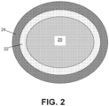
- FIG. 2 is a simplified cross-sectional view of fiber 20 coated with nucleating and BN layers 22 and 24, respectively. Method 10 is discussed together with FIGS. 1 and 2 .
- nucleating layer 22 can be deposited on a preform of multiple fibers 20. Nucleating layer 22 can be deposited to generally circumscribe each fiber 20 although discontinuities may exist. Each fiber 20 can be formed from SiC. Fibers 20 can be arranged in one of various two or three-dimensional woven architectures such as plain, harness (e.g., 3, 5, 8, etc.), twill, braid, tape layup, or non-symmetric to name a few non-limiting examples. Non-woven architectures (e.g., chopped, felted, etc.) are also contemplated herein.
- fibers 20 can be formed from the 3C polytype of SiC (i.e., 3C-SiC), also referred to as ⁇ -SiC, which has an a -lattice constant of about 4.4 ⁇ (4.4 x 10 -10 m).
- Nucleating layer 22 can include ruthenium (Ru) deposited via ALD using an Ru-based precursor with, for example, oxygen (O 2 ) at a temperature ranging from about 300°C to 400°C.
- the resulting layer can have a generally uniform thickness ranging from 2.0 nm to 20 nm, and more specifically in some embodiments, from 5.0 nm to 10 nm.
- ALD deposits can typically easily penetrate preforms (e.g., preform 20) of various (e.g., chopped, woven, etc.) fiber architectures.
- Ru can deposit in a hexagonal closed pack (HCP) crystalline form with an a -lattice constant of about 2.7 ⁇ (2.7 x 10 -10 m) and a c-lattice constant of about 4.3 ⁇ (4.3 x 10 -10 m).
- HCP hexagonal closed pack
- the c-lattice constant of Ru is generally within 3.0% of a -lattice constant of ⁇ -SiC (i.e., based on 4.3 ⁇ ⁇ 4.4 ⁇ ). Accordingly, a more cohesive boundary layer between fiber 20 and nucleating layer 22 can form.
- Alternative embodiments can instead deposit pyrolytic carbon as a nucleating material.
- BN layer 24 can be deposited on the surface of nucleating layer 22 (opposite fiber 20) via chemical vapor infiltration (CVI).
- CVI chemical vapor infiltration
- BN layer 24 can be deposited to generally circumscribe nucleating layer 22 of each fiber 20, although discontinuities may exist.
- Ordered forms of BN such as hexagonal BN (h-BN) and quasi-ordered turbostratic BN (t-BN) are preferred.
- the former in particular includes basal planes of covalently bonded B and N atoms aligned with the fiber axis. In an operational environment of a gas turbine engine, such nanostructure facilitates matrix sliding, relative to fiber 20, within BN layer 24, and debonding of BN layer 24 to protect fiber 20.
- h-BN is desirable within BN layer 24.
- nucleating layer 22 promotes epitaxial growth of h-BN with t-BN under typical CVI process conditions. Such conditions tend not to favor h-BN without significantly elevating the process temperature, which can, undesirably, make deposition of BN hard to control.
- Each of h-BN and t-BN have a -lattice constants of about 2.5 ⁇ (2.5 x 10 -10 m) such that the a -lattice constants of h-BN and/or t-BN are generally within 8.0% of the a -lattice constant of Ru.
- the a -lattice constant of h-BN in particular can range from 2.5 ⁇ to 2.9 ⁇ (2.5 x 10 -10 to 2.9 x 10 -10 ) such that the a -lattice constant of h-BN is within about 7.0% to 9.0% of the a -lattice constant of Ru.
- BN layer 24 may directly apply to fiber 20, with there being a relatively high degree of lattice mismatch between the a -lattice constant of ⁇ -SiC (4.4 ⁇ ) and the a -lattice constants of h-BN and t-BN.
- This can cause crystals of h-BN and/or t-BN to deform upon initial deposit leading to an amount of non-crystalline, amorphous BN (a-BN), which is more susceptible to oxidation and reactivity with water vapor at engine operating temperatures than crystalline forms of BN.
- a-BN amorphous BN
- Providing nucleating layer 22 according to the present method creates an adaptive bridge between fiber 20 and BN layer 24, as Ru has lattice constants corresponding to each of ⁇ -SiC and h-BN/t-BN.
- Step 16 can be an optional step for applying, using CVI, additional layers over BN layer 24, such as silicon-doped BN (Si-BN), silicon nitride (Si 3 N 4 ), carbon (C), SiC, and/or an additional BN layer, to name a few, non-limiting examples.
- Si-BN silicon-doped BN
- Si 3 N 4 silicon nitride
- C carbon
- SiC SiC
- an additional BN layer such as silicon-doped BN (Si-BN), silicon nitride (Si 3 N 4 ), carbon (C), SiC, and/or an additional BN layer, to name a few, non-limiting examples.
- the preform can be densified with a ceramic (e.g., SiC) matrix that infiltrates the preform of fibers 20 with any encompassing layers.
- Step 18 can immediately follow step 14 if no further layers, after BN layer 24, are desired.
- CVI can be used to infiltrate the preform with reactant vapors, and the process can be carried out until the resulting CMC has reached the desired residual porosity.
- Other techniques for matrix formation are contemplated herein, such as one or a combination of slurry infiltration, melt infiltration, and polymer infiltration and pyrolysis. Such techniques can supplement or precede the CVI process.
- Protective coatings for the CMC e.g., thermal barrier coatings, environmental barrier coatings, etc.
- a CMC component formed with the disclosed fiber coating arrangements can be incorporated into aerospace, maritime, or industrial equipment, to name a few, non-limiting examples.
- a method of forming a ceramic matrix composite includes arranging a plurality of fibers into a preform, each of the plurality of fibers being formed from silicon carbide, depositing a nucleating layer on the plurality of fibers, the nucleating layer comprising a crystalline material having an a -lattice constant and a c-lattice constant, and depositing a boron nitride layer on the nucleating layer.
- the c-lattice constant of the crystalline material of the nucleating layer corresponds to an a -lattice constant of the silicon carbide, such that the c -lattice constant of the crystalline material is within 3.0% of the a -lattice constant of the silicon carbide.
- the method of the preceding paragraph can optionally include, additionally and/or alternatively, any one or more of the following features, configurations and/or additional components:
- the boron nitride layer can include an amount of hexagonal boron nitride, the hexagonal boron nitride having an a -lattice constant corresponding to the a- lattice constant of the crystalline material of the nucleating layer, such that the a -lattice constant of hexagonal boron nitride is within 8.0% of the a -lattice constant of the crystalline material.
- the boron nitride layer can further include an amount of turbostratic boron nitride, the turbostratic boron nitride having an a -lattice constant corresponding to the a -lattice constant of the crystalline material of the nucleating layer, such that the a -lattice constant of turbostratic boron nitride is within 8.0% of the a -lattice constant of the crystalline material.
- the crystalline material of the nucleating layer can include ruthenium.
- the a -lattice constant of ruthenium can be 2.7 angstroms, and the c-lattice constant of ruthenium can be 4.3 angstroms.
- the a -lattice constant of hexagonal boron nitride can range from 2.5 angstroms to 2.9 angstroms.
- the silicon carbide can be ⁇ -silicon carbide.
- the c -lattice constant of the ⁇ -silicon carbide can be 4.4 angstroms.
- the nucleating layer can be deposited using atomic layer deposition.
- the boron nitride layer can be deposited using chemical vapor infiltration.
- the nucleating layer can be deposited such that it has a uniform thickness ranging from 2 nanometers to 20 nanometers.
- the thickness e.g. the thickness of the nucleating layer
- the thickness of the nucleating layer can range from 5 nanometers to 10 nanometers.
- Any of the above methods can further include densifying the preform with a ceramic matrix.
- densifying the preform can include at least one of: chemical vapor infiltration, slurry infiltration, melt infiltration, and polymer infiltration and pyrolysis.
- any of the above methods can further include, prior to the step of densifying the preform, depositing a further layer on the boron nitride layer comprising at least one of: silicon-doped boron nitride, silicon nitride, carbon, silicon carbide, and boron nitride.
- a method of forming a ceramic matrix composite includes arranging a plurality of fibers into a preform, each of the plurality of fibers being formed from silicon carbide, depositing a nucleating layer on the plurality of fibers, the nucleating layer comprising a crystalline material having an a -lattice constant and a c-lattice constant, and depositing a boron nitride layer on the nucleating layer, e.g. wherein the boron nitride comprises hexagonal boron nitride and turbostratic boron nitride.
- the a -lattice constant of the crystalline material of the nucleating layer corresponds to an a -lattice constant of each of the hexagonal boron nitride and turbostratic boron nitride, such that the a -lattice constant of the crystalline material is within 8.0% of the a -lattice constant of each of the hexagonal boron nitride and turbostratic boron nitride.
- the method of the preceding paragraph can optionally include, additionally and/or alternatively, any one or more of the following features, configurations and/or additional components:
- the c-lattice constant of the crystalline material of the nucleating layer can correspond to an a -lattice constant of the silicon carbide, such that the c -lattice constant of the crystalline material is within 3.0% of the a -lattice constant of the silicon carbide.
- the silicon carbide can be ⁇ -silicon carbide.
- the crystalline material of the nucleating layer can include ruthenium.
- Any of the above methods can further include densifying the preform with a ceramic matrix.
Landscapes
- Chemical & Material Sciences (AREA)
- Engineering & Computer Science (AREA)
- Ceramic Engineering (AREA)
- Manufacturing & Machinery (AREA)
- Materials Engineering (AREA)
- Organic Chemistry (AREA)
- Structural Engineering (AREA)
- Inorganic Chemistry (AREA)
- Chemical Kinetics & Catalysis (AREA)
- Mechanical Engineering (AREA)
- Metallurgy (AREA)
- General Chemical & Material Sciences (AREA)
- Nanotechnology (AREA)
- Chemical Vapour Deposition (AREA)
- Ceramic Products (AREA)
- Turbine Rotor Nozzle Sealing (AREA)
Abstract
A method of forming a ceramic matrix composite includes arranging a plurality of fibers into a preform, each of the plurality of fibers being formed from silicon carbide, depositing a nucleating layer on the plurality of fibers, the nucleating layer comprising a crystalline material having an a-lattice constant and a c-lattice constant, and depositing a boron nitride layer on the nucleating layer. The c-lattice constant of the crystalline material of the nucleating layer corresponds to an a-lattice constant of the silicon carbide, such that the c-lattice constant of the crystalline material is within 3.0% of the a-lattice constant of the silicon carbide.
Description
- The present invention relates to ceramic matrix composites, and more particularly to the formation of fiber-matrix interface coatings therein.
- Fiber-reinforced ceramic matrix composites (CMCs) are known and used for components that are exposed to high temperatures and corrosive conditions that can degrade other kinds of materials. Under such severe conditions, such as the operating conditions in aerospace and aircraft applications, even such ceramic materials are vulnerable to degradation. Over time, ceramic composite materials can form microcracks that further expose the ceramic material to oxygen or other corrosive elements, which form undesirable phases to the detriment of the properties of the ceramic matrix composite component.
- Fibers can be coated with a layer of boron nitride (BN) to form a weak interface between the fibers and matrix material to enable desired composite characteristics. However, BN can sometimes form with a disordered structure that readily oxidizes and can lead to diminished capacity for arresting and deflecting cracks. Therefore, composites based on such interfaces can lack sufficient durability and/or fracture toughness. Interface materials with a greater oxidation resistance are therefore desirable.
- A method of forming a ceramic matrix composite includes arranging a plurality of fibers into a preform, each of the plurality of fibers being formed from silicon carbide, depositing a nucleating layer on the plurality of fibers, the nucleating layer comprising a crystalline material having an a-lattice constant and a c-lattice constant, and depositing a boron nitride layer on the nucleating layer. The c-lattice constant of the crystalline material of the nucleating layer corresponds to an a-lattice constant of the silicon carbide, such that the c-lattice constant of the crystalline material is within 3.0% of the a-lattice constant of the silicon carbide.
- A method of forming a ceramic matrix composite includes arranging a plurality of fibers into a preform, each of the plurality of fibers being formed from silicon carbide, depositing a nucleating layer on the plurality of fibers, the nucleating layer comprising a crystalline material having an a-lattice constant and a c-lattice constant, and depositing a boron nitride layer on the nucleating layer (e.g. wherein the boron nitride comprises hexagonal boron nitride and turbostratic boron nitride). The a-lattice constant of the crystalline material of the nucleating layer corresponds to an a-lattice constant of each of the hexagonal boron nitride and turbostratic boron nitride, such that the a-lattice constant of the crystalline material is within 8.0% of the a-lattice constant of each of the hexagonal boron nitride and turbostratic boron nitride.
- Certain exemplary embodiments will now be described in greater detail by way of example only and with reference to the accompanying drawings in which:
-
FIG. 1 is a flowchart illustrating a method of forming a CMC with an interface coating including an amount of crystalline BN. -
FIG. 2 is a simplified cross-sectional illustration of a fiber coated with a nucleating layer and a BN layer. - While the above-identified figures set forth one or more embodiments of the present disclosure, other embodiments are also contemplated, as noted in the discussion. In all cases, this disclosure presents the invention by way of representation and not limitation. It should be understood that numerous other modifications and embodiments can be devised by those skilled in the art, which fall within the scope and spirit of the principles of the invention. The figures may not be drawn to scale, and applications and embodiments of the present invention may include features and components not specifically shown in the drawings.
- This disclosure presents a CMC component with a highly crystalline BN interface coating (IFC) layer and a method of forming such a component. A nucleating layer can be deposited, via atomic layer deposition (ALD) on the silicon carbide (SiC) fibers of a preform to promote the formation of more ordered and aligned forms of BN within the IFC. The ordered BN imparts improved fracture toughness and oxidation resistance to the CMC component which can be, for example, incorporated into a gas turbine engine.
-
FIG. 1 is a method flowchart illustrating select steps ofmethod 10 for fabricating a CMC which includescrystalline BN layer 24.FIG. 2 is a simplified cross-sectional view offiber 20 coated with nucleating andBN layers Method 10 is discussed together withFIGS. 1 and2 . - At
step 12, nucleatinglayer 22 can be deposited on a preform ofmultiple fibers 20. Nucleatinglayer 22 can be deposited to generally circumscribe eachfiber 20 although discontinuities may exist. Eachfiber 20 can be formed from SiC.Fibers 20 can be arranged in one of various two or three-dimensional woven architectures such as plain, harness (e.g., 3, 5, 8, etc.), twill, braid, tape layup, or non-symmetric to name a few non-limiting examples. Non-woven architectures (e.g., chopped, felted, etc.) are also contemplated herein. In an exemplary embodiment,fibers 20 can be formed from the 3C polytype of SiC (i.e., 3C-SiC), also referred to as β-SiC, which has an a-lattice constant of about 4.4 Å (4.4 x 10⁻¹⁰ m). - Nucleating
layer 22 can include ruthenium (Ru) deposited via ALD using an Ru-based precursor with, for example, oxygen (O2) at a temperature ranging from about 300°C to 400°C. The resulting layer can have a generally uniform thickness ranging from 2.0 nm to 20 nm, and more specifically in some embodiments, from 5.0 nm to 10 nm. ALD deposits can typically easily penetrate preforms (e.g., preform 20) of various (e.g., chopped, woven, etc.) fiber architectures. Using ALD, Ru can deposit in a hexagonal closed pack (HCP) crystalline form with an a-lattice constant of about 2.7 Å (2.7 x 10⁻¹⁰ m) and a c-lattice constant of about 4.3 Å (4.3 x 10⁻¹⁰m). Thus, there is a high degree of lattice match between the a-lattice of the underlying β-SiC (4.4 Å) and the c-lattice of Ru (4.3 Å). Stated another way, the c-lattice constant of Ru is generally within 3.0% of a-lattice constant of β-SiC (i.e., based on 4.3 Å ÷ 4.4 Å). Accordingly, a more cohesive boundary layer betweenfiber 20 and nucleatinglayer 22 can form. Alternative embodiments can instead deposit pyrolytic carbon as a nucleating material. - At
step 14, BNlayer 24 can be deposited on the surface of nucleating layer 22 (opposite fiber 20) via chemical vapor infiltration (CVI).BN layer 24 can be deposited to generally circumscribenucleating layer 22 of eachfiber 20, although discontinuities may exist. Ordered forms of BN, such as hexagonal BN (h-BN) and quasi-ordered turbostratic BN (t-BN) are preferred. The former in particular includes basal planes of covalently bonded B and N atoms aligned with the fiber axis. In an operational environment of a gas turbine engine, such nanostructure facilitates matrix sliding, relative tofiber 20, withinBN layer 24, and debonding ofBN layer 24 to protectfiber 20. Thus, h-BN is desirable withinBN layer 24. The presence of nucleatinglayer 22 promotes epitaxial growth of h-BN with t-BN under typical CVI process conditions. Such conditions tend not to favor h-BN without significantly elevating the process temperature, which can, undesirably, make deposition of BN hard to control. Each of h-BN and t-BN have a-lattice constants of about 2.5 Å (2.5 x 10⁻¹⁰ m) such that the a-lattice constants of h-BN and/or t-BN are generally within 8.0% of the a-lattice constant of Ru. Accordingly, there is a high degree of lattice match between the a-lattice of h-BN and/or t-BN with the a-lattice of Ru within nucleatinglayer 22. In some cases, the a-lattice constant of h-BN in particular can range from 2.5 Å to 2.9 Å (2.5 x 10⁻¹⁰ to 2.9 x 10⁻¹⁰) such that the a-lattice constant of h-BN is within about 7.0% to 9.0% of the a-lattice constant of Ru. - In contrast, traditional coating schemes may directly apply
BN layer 24 tofiber 20, with there being a relatively high degree of lattice mismatch between the a-lattice constant of β-SiC (4.4 Å) and the a-lattice constants of h-BN and t-BN. This can cause crystals of h-BN and/or t-BN to deform upon initial deposit leading to an amount of non-crystalline, amorphous BN (a-BN), which is more susceptible to oxidation and reactivity with water vapor at engine operating temperatures than crystalline forms of BN. Providingnucleating layer 22 according to the present method creates an adaptive bridge betweenfiber 20 andBN layer 24, as Ru has lattice constants corresponding to each of β-SiC and h-BN/t-BN. -
Step 16 can be an optional step for applying, using CVI, additional layers overBN layer 24, such as silicon-doped BN (Si-BN), silicon nitride (Si3N4), carbon (C), SiC, and/or an additional BN layer, to name a few, non-limiting examples. - At
step 18, the preform can be densified with a ceramic (e.g., SiC) matrix that infiltrates the preform offibers 20 with any encompassing layers.Step 18 can immediately followstep 14 if no further layers, afterBN layer 24, are desired. CVI can be used to infiltrate the preform with reactant vapors, and the process can be carried out until the resulting CMC has reached the desired residual porosity. Other techniques for matrix formation are contemplated herein, such as one or a combination of slurry infiltration, melt infiltration, and polymer infiltration and pyrolysis. Such techniques can supplement or precede the CVI process. Protective coatings for the CMC (e.g., thermal barrier coatings, environmental barrier coatings, etc.) can optionally be applied afterstep 18. - A CMC component formed with the disclosed fiber coating arrangements can be incorporated into aerospace, maritime, or industrial equipment, to name a few, non-limiting examples.
- The following are non-exclusive descriptions of possible embodiments of the present invention.
- A method of forming a ceramic matrix composite includes arranging a plurality of fibers into a preform, each of the plurality of fibers being formed from silicon carbide, depositing a nucleating layer on the plurality of fibers, the nucleating layer comprising a crystalline material having an a-lattice constant and a c-lattice constant, and depositing a boron nitride layer on the nucleating layer. The c-lattice constant of the crystalline material of the nucleating layer corresponds to an a-lattice constant of the silicon carbide, such that the c-lattice constant of the crystalline material is within 3.0% of the a-lattice constant of the silicon carbide.
- The method of the preceding paragraph can optionally include, additionally and/or alternatively, any one or more of the following features, configurations and/or additional components:
- In the above method, the boron nitride layer can include an amount of hexagonal boron nitride, the hexagonal boron nitride having an a-lattice constant corresponding to the a-lattice constant of the crystalline material of the nucleating layer, such that the a-lattice constant of hexagonal boron nitride is within 8.0% of the a-lattice constant of the crystalline material.
- In any of the above methods, the boron nitride layer can further include an amount of turbostratic boron nitride, the turbostratic boron nitride having an a-lattice constant corresponding to the a-lattice constant of the crystalline material of the nucleating layer, such that the a-lattice constant of turbostratic boron nitride is within 8.0% of the a-lattice constant of the crystalline material.
- In any of the above methods, the crystalline material of the nucleating layer can include ruthenium.
- In any of the above methods, the a-lattice constant of ruthenium can be 2.7 angstroms, and the c-lattice constant of ruthenium can be 4.3 angstroms.
- In any of the above methods, the a-lattice constant of hexagonal boron nitride can range from 2.5 angstroms to 2.9 angstroms.
- In any of the above methods, the silicon carbide can be β-silicon carbide.
- In any of the above methods, the c-lattice constant of the β-silicon carbide can be 4.4 angstroms.
- In any of the above methods, the nucleating layer can be deposited using atomic layer deposition.
- In any of the above methods, the boron nitride layer can be deposited using chemical vapor infiltration.
- In any of the above methods, the nucleating layer can be deposited such that it has a uniform thickness ranging from 2 nanometers to 20 nanometers.
- In any of the above methods, the thickness, e.g. the thickness of the nucleating layer, can range from 5 nanometers to 10 nanometers.
- Any of the above methods can further include densifying the preform with a ceramic matrix.
- In any of the above methods, densifying the preform can include at least one of: chemical vapor infiltration, slurry infiltration, melt infiltration, and polymer infiltration and pyrolysis.
- Any of the above methods can further include, prior to the step of densifying the preform, depositing a further layer on the boron nitride layer comprising at least one of: silicon-doped boron nitride, silicon nitride, carbon, silicon carbide, and boron nitride.
- A method of forming a ceramic matrix composite includes arranging a plurality of fibers into a preform, each of the plurality of fibers being formed from silicon carbide, depositing a nucleating layer on the plurality of fibers, the nucleating layer comprising a crystalline material having an a-lattice constant and a c-lattice constant, and depositing a boron nitride layer on the nucleating layer, e.g. wherein the boron nitride comprises hexagonal boron nitride and turbostratic boron nitride. The a-lattice constant of the crystalline material of the nucleating layer corresponds to an a-lattice constant of each of the hexagonal boron nitride and turbostratic boron nitride, such that the a-lattice constant of the crystalline material is within 8.0% of the a-lattice constant of each of the hexagonal boron nitride and turbostratic boron nitride.
- The method of the preceding paragraph can optionally include, additionally and/or alternatively, any one or more of the following features, configurations and/or additional components:
- In the above method, the c-lattice constant of the crystalline material of the nucleating layer can correspond to an a-lattice constant of the silicon carbide, such that the c-lattice constant of the crystalline material is within 3.0% of the a-lattice constant of the silicon carbide.
- In any of the above methods, the silicon carbide can be β-silicon carbide.
- In any of the above methods, the crystalline material of the nucleating layer can include ruthenium.
- Any of the above methods can further include densifying the preform with a ceramic matrix.
- While the invention has been described with reference to an exemplary embodiment(s), it will be understood by those skilled in the art that various changes may be made and equivalents may be substituted for elements thereof without departing from the scope of the invention. In addition, many modifications may be made to adapt a particular situation or material to the teachings of the invention without departing from the essential scope thereof. Therefore, it is intended that the invention not be limited to the particular embodiment(s) disclosed, but that the invention will include all embodiments falling within the scope of the appended claims.
- Certain embodiments of the present disclosure are set out below.
- 1. A method of forming a ceramic matrix composite, the method comprising:
- arranging a plurality of fibers into a preform, each of the plurality of fibers being formed from silicon carbide;
- depositing a nucleating layer on the plurality of fibers, the nucleating layer comprising a crystalline material having an a-lattice constant and a c-lattice constant; and
- depositing a boron nitride layer on the nucleating layer;
- wherein the c-lattice constant of the crystalline material of the nucleating layer corresponds to an a-lattice constant of the silicon carbide, such that the c-lattice constant of the crystalline material is within 3.0% of the a-lattice constant of the silicon carbide.
- 2. The method of embodiment 1, wherein the boron nitride layer comprises an amount of hexagonal boron nitride, the hexagonal boron nitride having an a-lattice constant corresponding to the a-lattice constant of the crystalline material of the nucleating layer, such that the a-lattice constant of hexagonal boron nitride is within 8.0% of the a-lattice constant of the crystalline material.
- 3. The method of embodiment 1, wherein the boron nitride layer further comprises an amount of turbostratic boron nitride, the turbostratic boron nitride having an a-lattice constant corresponding to the a-lattice constant of the crystalline material of the nucleating layer, such that the a-lattice constant of turbostratic boron nitride is within 8.0% of the a-lattice constant of the crystalline material.
- 4. The method of embodiment 2, wherein the crystalline material of the nucleating layer comprises ruthenium.
- 5. The method of embodiment 4, wherein the a-lattice constant of ruthenium is 2.7 angstroms, and wherein the c-lattice constant of ruthenium is 4.3 angstroms.
- 6. The method of embodiment 5, wherein the a-lattice constant of hexagonal boron nitride ranges from 2.5 angstroms to 2.9 angstroms.
- 7. The method of embodiment 5, wherein the silicon carbide is β-silicon carbide.
- 8. The method of embodiment 7, wherein the c-lattice constant of the β-silicon carbide is 4.4 angstroms.
- 9. The method of embodiment 2, wherein the nucleating layer is deposited using atomic layer deposition.
- 10. The method of embodiment 2, wherein the boron nitride layer is deposited using chemical vapor infiltration.
- 11. The method of embodiment 2, wherein the nucleating layer is deposited such that it has a uniform thickness ranging from 2 nanometers to 20 nanometers.
- 12. The method of embodiment 11, wherein the thickness ranges from 5 nanometers to 10 nanometers.
- 13. The method of embodiment 2 and further comprising: densifying the preform with a ceramic matrix.
- 14. The method of embodiment 13, wherein densifying the preform comprises at least one of: chemical vapor infiltration, slurry infiltration, melt infiltration, and polymer infiltration and pyrolysis.
- 15. The method of embodiment 13 and further comprising: prior to the step of densifying the preform, depositing a further layer on the boron nitride layer comprising at least one of: silicon-doped boron nitride, silicon nitride, carbon, silicon carbide, and boron nitride.
- 16. A method of forming a ceramic matrix composite, the method comprising:
- arranging a plurality of fibers into a preform, each of the plurality of fibers being formed from silicon carbide;
- depositing a nucleating layer on the plurality of fibers, the nucleating layer comprising a crystalline material having an a-lattice constant and a c-lattice constant; and
- depositing a boron nitride layer on the nucleating layer, the boron nitride comprising hexagonal boron nitride and turbostratic boron nitride;
- wherein the a-lattice constant of the crystalline material of the nucleating layer corresponds to an a-lattice constant of each of the hexagonal boron nitride and turbostratic boron nitride, such that the a-lattice constant of the crystalline material is within 8.0% of the a-lattice constant of each of the hexagonal boron nitride and turbostratic boron nitride.
- 17. The method of
embodiment 16, wherein the c-lattice constant of the crystalline material of the nucleating layer corresponds to an a-lattice constant of the silicon carbide, such that the c-lattice constant of the crystalline material is within 3.0% of the a-lattice constant of the silicon carbide. - 18. The method of embodiment 17, wherein the silicon carbide is β-silicon carbide.
- 19. The method of
embodiment 16, wherein the crystalline material of the nucleating layer comprises ruthenium. - 20. The method of
embodiment 16 and further comprising: densifying the preform with a ceramic matrix.
Claims (15)
- A method of forming a ceramic matrix composite, the method comprising:arranging a plurality of fibers into a preform, each of the plurality of fibers being formed from silicon carbide;depositing a nucleating layer on the plurality of fibers, the nucleating layer comprising a crystalline material having an a-lattice constant and a c-lattice constant; anddepositing a boron nitride layer on the nucleating layer;wherein the c-lattice constant of the crystalline material of the nucleating layer corresponds to an a-lattice constant of the silicon carbide, such that the c-lattice constant of the crystalline material is within 3.0% of the a-lattice constant of the silicon carbide.
- The method of claim 1, wherein the boron nitride layer comprises an amount of hexagonal boron nitride, the hexagonal boron nitride having an a-lattice constant corresponding to the a-lattice constant of the crystalline material of the nucleating layer, such that the a-lattice constant of hexagonal boron nitride is within 8.0% of the a-lattice constant of the crystalline material.
- The method of claim 1 or claim 2, wherein the boron nitride layer further comprises an amount of turbostratic boron nitride, the turbostratic boron nitride having an a-lattice constant corresponding to the a-lattice constant of the crystalline material of the nucleating layer, such that the a-lattice constant of turbostratic boron nitride is within 8.0% of the a-lattice constant of the crystalline material.
- A method of forming a ceramic matrix composite, the method comprising:arranging a plurality of fibers into a preform, each of the plurality of fibers being formed from silicon carbide;depositing a nucleating layer on the plurality of fibers, the nucleating layer comprising a crystalline material having an a-lattice constant and a c-lattice constant; anddepositing a boron nitride layer on the nucleating layer, the boron nitride comprising hexagonal boron nitride and turbostratic boron nitride;wherein the a-lattice constant of the crystalline material of the nucleating layer corresponds to an a-lattice constant of each of the hexagonal boron nitride and turbostratic boron nitride, such that the a-lattice constant of the crystalline material is within 8.0% of the a-lattice constant of each of the hexagonal boron nitride and turbostratic boron nitride.
- The method of claim 4, wherein the c-lattice constant of the crystalline material of the nucleating layer corresponds to an a-lattice constant of the silicon carbide, such that the c-lattice constant of the crystalline material is within 3.0% of the a-lattice constant of the silicon carbide.
- The method of any preceding claim, wherein the crystalline material of the nucleating layer comprises ruthenium.
- The method of claim 6, wherein the a-lattice constant of ruthenium is 2.7 angstroms, and wherein the c-lattice constant of ruthenium is 4.3 angstroms.
- The method of any one of claims 2 to 7, wherein the a-lattice constant of hexagonal boron nitride ranges from 2.5 angstroms to 2.9 angstroms.
- The method of any preceding claim, wherein the silicon carbide is β-silicon carbide, optionally wherein the c-lattice constant of the β-silicon carbide is 4.4 angstroms.
- The method of any preceding claim, wherein the nucleating layer is deposited using atomic layer deposition.
- The method of any preceding claim, wherein the boron nitride layer is deposited using chemical vapor infiltration.
- The method of any preceding claim, wherein the nucleating layer is deposited such that it has a uniform thickness ranging from 2 nanometers to 20 nanometers, optionally wherein the thickness ranges from 5 nanometers to 10 nanometers.
- The method of any preceding claim, further comprising: densifying the preform with a ceramic matrix.
- The method of claim 13, wherein densifying the preform comprises at least one of:
chemical vapor infiltration, slurry infiltration, melt infiltration, and polymer infiltration and pyrolysis. - The method of claim 13 or claim 14, further comprising: prior to the step of densifying the preform, depositing a further layer on the boron nitride layer comprising at least one of: silicon-doped boron nitride, silicon nitride, carbon, silicon carbide, and boron nitride.
Applications Claiming Priority (1)
| Application Number | Priority Date | Filing Date | Title |
|---|---|---|---|
| US18/108,929 US12583798B2 (en) | 2023-02-13 | 2023-02-13 | Atomic layer deposition method enhancing the nucleation and crystallinity of a boron nitride interface coating on a silicon carbide fiber |
Publications (1)
| Publication Number | Publication Date |
|---|---|
| EP4414344A1 true EP4414344A1 (en) | 2024-08-14 |
Family
ID=89853575
Family Applications (1)
| Application Number | Title | Priority Date | Filing Date |
|---|---|---|---|
| EP24156022.6A Pending EP4414344A1 (en) | 2023-02-13 | 2024-02-06 | Atomic layer deposition method enhancing the nucleation and crystallinity of a boron nitride interface coating on a silicon carbide fiber |
Country Status (2)
| Country | Link |
|---|---|
| US (1) | US12583798B2 (en) |
| EP (1) | EP4414344A1 (en) |
Citations (1)
| Publication number | Priority date | Publication date | Assignee | Title |
|---|---|---|---|---|
| US20220178262A1 (en) * | 2020-12-03 | 2022-06-09 | Raytheon Technologies Corporation | Ceramic component |
Family Cites Families (3)
| Publication number | Priority date | Publication date | Assignee | Title |
|---|---|---|---|---|
| US10658472B2 (en) | 2016-05-12 | 2020-05-19 | Globalwafers Co., Ltd. | Direct formation of hexagonal boron nitride on silicon based dielectrics |
| US20170342844A1 (en) | 2016-05-31 | 2017-11-30 | United Technologies Corporation | High Temperature Composites With Enhanced Matrix |
| US10801108B2 (en) * | 2017-08-28 | 2020-10-13 | Raytheon Technologies Corporation | Method for fabricating ceramic matrix composite components |
-
2023
- 2023-02-13 US US18/108,929 patent/US12583798B2/en active Active
-
2024
- 2024-02-06 EP EP24156022.6A patent/EP4414344A1/en active Pending
Patent Citations (1)
| Publication number | Priority date | Publication date | Assignee | Title |
|---|---|---|---|---|
| US20220178262A1 (en) * | 2020-12-03 | 2022-06-09 | Raytheon Technologies Corporation | Ceramic component |
Also Published As
| Publication number | Publication date |
|---|---|
| US20240270652A1 (en) | 2024-08-15 |
| US12583798B2 (en) | 2026-03-24 |
Similar Documents
| Publication | Publication Date | Title |
|---|---|---|
| US11168032B2 (en) | Method of forming in-situ boron nitride for ceramic matrix composite environmental protection | |
| US10370301B2 (en) | Ceramic matrix composite and method and article of manufacture | |
| US20050181192A1 (en) | Fiber-reinforced ceramic composite material comprising a matrix with a nanolayered microstructure | |
| EP3957619B1 (en) | Method of making a ceramic matrix composite that exhibits chemical resistance | |
| US5558907A (en) | Pseudo-porous fiber coating for toughened ceramic composite materials and method of producing same | |
| EP2970020B1 (en) | Ceramic matrix composites and methods for producing ceramic matrix composites | |
| US12410107B2 (en) | Nanolaminate fiber interface coatings for composites | |
| US20120164430A1 (en) | Composite material part having a ceramic matrix, and method for manufacturing same | |
| JP7752004B2 (en) | Method for making ceramic matrix composites that exhibit moisture and environmental resistance | |
| EP1640352B1 (en) | Low cost manufacturing process for high performance ceramic matrix composites | |
| US12583798B2 (en) | Atomic layer deposition method enhancing the nucleation and crystallinity of a boron nitride interface coating on a silicon carbide fiber | |
| CA2794693A1 (en) | Sic fiber-bonded ceramic coated with sic | |
| US12565454B2 (en) | Multilayer interface coating with thermally-grown oxide for improved durability | |
| US5523035A (en) | Process for producing carbonaceous material | |
| US20260109651A1 (en) | Method for fabricating interface coatings | |
| US11873249B2 (en) | Method to form aligned interface coating on silicon carbide fibers | |
| JP3076914B2 (en) | Method for producing fiber-reinforced ceramic composite material | |
| EP0428977B1 (en) | Process for producing carbonaceous material | |
| JPH1045480A (en) | Coating for coating inorganic fiber for fiber reinforced composite material, inorganic fiber and fiber reinforced composite material containing the same | |
| US12545629B1 (en) | Functional tailoring of oxidation protection systems of carbon-carbon composites | |
| FR3081475A1 (en) | PROCESS FOR TREATING SILICON CARBIDE FIBERS BY CHEMICAL VAPOR DEPOSITION | |
| JP2000219584A (en) | Carbon fiber reinforced carbon composite material coated with silicon carbide and its production | |
| CN118271104A (en) | A method for preparing an oxidation-resistant carbon-carbon composite material using a multilayer coating | |
| Tang et al. | Preparation of Compositionally Graded CVD SiC Oxidation-Resistant Coating |
Legal Events
| Date | Code | Title | Description |
|---|---|---|---|
| PUAI | Public reference made under article 153(3) epc to a published international application that has entered the european phase |
Free format text: ORIGINAL CODE: 0009012 |
|
| STAA | Information on the status of an ep patent application or granted ep patent |
Free format text: STATUS: THE APPLICATION HAS BEEN PUBLISHED |
|
| AK | Designated contracting states |
Kind code of ref document: A1 Designated state(s): AL AT BE BG CH CY CZ DE DK EE ES FI FR GB GR HR HU IE IS IT LI LT LU LV MC ME MK MT NL NO PL PT RO RS SE SI SK SM TR |
|
| STAA | Information on the status of an ep patent application or granted ep patent |
Free format text: STATUS: REQUEST FOR EXAMINATION WAS MADE |
|
| 17P | Request for examination filed |
Effective date: 20250122 |