EP4414277A1 - Tag applicator device for a packaging line configured for forming, sealing and folding a plurality of packages containing a pourable product - Google Patents
Tag applicator device for a packaging line configured for forming, sealing and folding a plurality of packages containing a pourable product Download PDFInfo
- Publication number
- EP4414277A1 EP4414277A1 EP24154605.0A EP24154605A EP4414277A1 EP 4414277 A1 EP4414277 A1 EP 4414277A1 EP 24154605 A EP24154605 A EP 24154605A EP 4414277 A1 EP4414277 A1 EP 4414277A1
- Authority
- EP
- European Patent Office
- Prior art keywords
- tags
- along
- packages
- applicator device
- gripper member
- Prior art date
- Legal status (The legal status is an assumption and is not a legal conclusion. Google has not performed a legal analysis and makes no representation as to the accuracy of the status listed.)
- Pending
Links
Images


Classifications
-
- B—PERFORMING OPERATIONS; TRANSPORTING
- B65—CONVEYING; PACKING; STORING; HANDLING THIN OR FILAMENTARY MATERIAL
- B65C—LABELLING OR TAGGING MACHINES, APPARATUS, OR PROCESSES
- B65C9/00—Details of labelling machines or apparatus
- B65C9/08—Label feeding
- B65C9/18—Label feeding from strips, e.g. from rolls
- B65C9/1865—Label feeding from strips, e.g. from rolls the labels adhering on a backing strip
- B65C9/1876—Label feeding from strips, e.g. from rolls the labels adhering on a backing strip and being transferred by suction means
- B65C9/1884—Label feeding from strips, e.g. from rolls the labels adhering on a backing strip and being transferred by suction means the suction means being a movable vacuum arm or pad
-
- B—PERFORMING OPERATIONS; TRANSPORTING
- B65—CONVEYING; PACKING; STORING; HANDLING THIN OR FILAMENTARY MATERIAL
- B65C—LABELLING OR TAGGING MACHINES, APPARATUS, OR PROCESSES
- B65C9/00—Details of labelling machines or apparatus
- B65C9/08—Label feeding
- B65C9/18—Label feeding from strips, e.g. from rolls
- B65C9/1865—Label feeding from strips, e.g. from rolls the labels adhering on a backing strip
-
- B—PERFORMING OPERATIONS; TRANSPORTING
- B65—CONVEYING; PACKING; STORING; HANDLING THIN OR FILAMENTARY MATERIAL
- B65C—LABELLING OR TAGGING MACHINES, APPARATUS, OR PROCESSES
- B65C9/00—Details of labelling machines or apparatus
- B65C9/40—Controls; Safety devices
- B65C9/42—Label feed control
-
- B—PERFORMING OPERATIONS; TRANSPORTING
- B65—CONVEYING; PACKING; STORING; HANDLING THIN OR FILAMENTARY MATERIAL
- B65C—LABELLING OR TAGGING MACHINES, APPARATUS, OR PROCESSES
- B65C9/00—Details of labelling machines or apparatus
- B65C9/0015—Preparing the labels or articles, e.g. smoothing, removing air bubbles
- B65C2009/0018—Preparing the labels
- B65C2009/0021—Preparing the labels for temporary attachment to transfer means or to the article
- B65C2009/0025—Preparing the labels for temporary attachment to transfer means or to the article by electrostatical charge
Definitions
- the present invention relates to a tag applicator device for a packaging line configured for forming, sealing and folding a plurality of packages containing a pourable product, in particular a pourable food product.
- the applicator device is configured for applying informative tags onto such packages, such as QR code tags, RFID tags, tags provided with a temperature sensor, or the like.
- pourable food products such as fruit juice, UHT (ultra-high temperature-treated) milk, wine, tomato sauce, etc.
- UHT ultra-high temperature-treated milk
- wine tomato sauce
- etc. are sold in packages made of sterilized packaging material.
- a typical example is the parallelepiped-shaped package for pourable food products known as Tetra Brik Aseptic (registered trademark), which is made by folding and sealing a laminated web of packaging material.
- the packaging material has a multilayer structure comprising a base layer, e.g. made of paper, covered on both sides with layers of heat-seal plastic material, e.g. polyethylene.
- the packaging material also comprises a layer of oxygen-barrier material, e.g. an aluminum foil, which is superimposed on a layer of heat-seal plastic material, and is in turn covered with another layer of heat-seal plastic material forming the inner face of the package eventually contacting the food product.
- a layer of oxygen-barrier material e.g. an aluminum foil
- Such packages are usually produced in fully automatic packaging lines, in which a continuous tube is formed starting from a web of packaging material initially wound in a reel and fed through a plurality of unwinding rollers of such packaging line.
- the web of packaging material is sterilized in the packaging machine, e.g. by applying a chemical sterilizing agent, such as hydrogen peroxide solution, which, once sterilization is completed, is removed from the surfaces of the packaging material, e.g. evaporated by heating.
- the web so sterilized is then maintained in a closed, sterile environment, and, advanced by the aforementioned unwinding rollers, is folded and sealed longitudinally to form the tube by means of a known web folding device.
- the tube is fed continuously along a first direction, normally a straight vertical direction, is filled with the sterilized food product from above and is formed, sealed and subsequently cut along equally spaced transversal cross-sections extending along a second direction, normally a direction orthogonal to the first direction.
- the known packaging lines comprise a forming device configured to form the tube, so as to imprint an external shape to it corresponding to the desired shape of the package, and a sealing device configured to seal the tube at equally spaced cross-sections orthogonal to the tube advancement direction.
- a packaging line of the above type is known from WO-A-2007114752 .
- Such packaging machine comprises a pair of alternately movable forming and sealing jaws which are controllable with a reciprocating movement in the first direction and in a third direction orthogonal to the first direction and second direction to interact with the tube at successive portions thereof.
- pillow packs are obtained thereby, which have a longitudinal sealing band, a top transversal sealing band and a bottom transversal sealing band.
- the pillow packs are then cut at the cross-sections to be separated from one another and directed to a folding device of the packaging machine for the final folding thereof.
- the sealing device and the forming device are moved to be ready to grip another subsequent portion of the tube.
- Such informative tags are defined by QR-code tags (i.e. tags onto which a QR-code is printed), RFID tags, tags provided with a temperature sensor, or the like.
- the informative tags are usually applied onto the finished packages at an application station located operatively downstream of the aforementioned folding device.
- a known packaging line includes a tag applicator device arranged operatively downstream of the folding device.
- the tag applicator may comprise:
- the tags are of the self-adhesive type and are initially provided attached on a support strip initially wound in form of reel.
- the web of labelling material includes the support strip and the tags attached thereto consecutively along the longitudinal direction of the strip itself.
- the feeder includes:
- the deflector plate is directly arranged at the application station, in a position adjacent to the conveyor belt and substantially tangent to the conveying path, so that each tag detached from the support strip is directly attached to one respective package advanced along the conveying path and transiting at the application station.
- number 1 indicates as a whole a tag applicator device for applying tags 2 onto packages 3 containing a pourable product, preferably a pourable food product such as pasteurized or UHT milk, water, fruit juice, wine, peas, beans, etc.
- a pourable food product such as pasteurized or UHT milk, water, fruit juice, wine, peas, beans, etc.
- applicator device 1 is part of a packaging line (known per se and not shown) configured for producing a plurality of such packages 3 in a known manner, starting from a tube (not shown) of packaging material.
- the packaging line comprises a packaging machine configured for forming, sealing and folding packages 3 starting from such tube.
- the packaging machine comprises:
- the packaging machine is configured to form and seal a plurality of pillow packs containing the pourable product starting from the tube and then to fold the pillow packs for obtaining the aforementioned formed, sealed and folded packages 3 containing the pourable product.
- the packaging material has a multilayer structure (not shown), and comprises a layer of fibrous material, e.g. paper, covered on both sides with respective layers of heat-seal plastic material, e.g. polyethylene.
- a layer of fibrous material e.g. paper
- heat-seal plastic material e.g. polyethylene
- the packaging material also comprises a layer of gas-and-light barrier material, e.g. aluminum foil or ethylene vinyl alcohol (EVOH) film, which is superimposed on a layer of heat-seal plastic material, and is in turn covered with another layer of heat-seal plastic material, the latter forming the inner face of package 3 eventually contacting the pourable product.
- gas-and-light barrier material e.g. aluminum foil or ethylene vinyl alcohol (EVOH) film
- applicator device 1 is configured to apply onto packages 3 tags 2 of the informative type, such as QR-code tags (i.e. tags onto which a QR-code is printed), RFID tags, tags provided with a temperature sensor, or the like.
- tags 2 of the informative type such as QR-code tags (i.e. tags onto which a QR-code is printed), RFID tags, tags provided with a temperature sensor, or the like.
- applicator device 1 is opportunely arranged operatively downstream of the folding device.
- Applicator device 1 may comprise one or more of:
- Web 6 comprises a longitudinal sequence of tags 2, i.e. a plurality of tags 2 arranged along the longitudinal direction of web 6.
- web 6 comprises, in particular is defined by, a support strip on which a longitudinal sequence of tags 2 is initially attached to.
- tags 2 are preferably defined by pieces of labelling material of the self-adhesive type.
- conveyor 4 is conveniently arranged downstream of the folding device for receiving packages 3 therefrom.
- feeder 5 includes:
- deflector plate 11 defines a very narrow angle of feed path P, which obliges web 6 to make a very narrow turn, thereby causing tags 2 to detach from the support strip.
- feeder 5 further comprises a collection roller 12 for collecting the spent web 6, i.e. for collecting the support strip downstream of deflector plate 11 from which tags 2 have been already detached.
- applicator device 1 comprises a transfer device 13, e.g. operatively interposed between feeder 5 and conveyor 4.
- the transfer device 13 is configured to sequentially receive tags 2 (from feeder 5) at a receiving station R, to transfer tags 2 to conveyor 4 at an application station A, and to apply tags 2 onto packages 3, respectively, at application station A.
- receiving station R is operatively interposed between transfer device 13 and feeder 5, namely is operatively shared by these latter.
- application station A is operatively interposed between transfer device 13 and conveyor 4, namely is operatively shared by these latter.
- Transfer device 13 includes at least one gripper member 14 for retaining at least one tag 2 at a time.
- gripper member 14 is cyclically movable between receiving station R, at which it receives a tag 2, and application station A, at which it releases such tag 2 onto one respective package 3.
- Transfer device 13 is arranged adjacent to both feeder 5 and conveyor 4.
- deflector plate 11 is located at receiving station R, for cyclically supplying gripper member 14 with one detached tag 2 at a time, and application station A is arranged along conveying path L, so that each tag 2 is transferred to one respective package 3.
- applicator device 1 further comprises:
- sensor 15 is configured to determine a package succession information along conveying path L based on said detection.
- control unit 16 is configured to control the movement of gripper member 14 between receiving station R and application station A based on said package succession information.
- transfer device 13 comprises:
- carts 18 are movable along a closed-loop advancing path Q.
- carts 18 and track 17 define a rail-slide coupling.
- carts 18 levitate with respect to track 17.
- transfer device 13 comprises a linear motor actuator configured for driving the movement of carts 18 along path Q.
- the linear motor actuator includes a plurality of electrically powerable solenoids (not shown) distributed along track 17 and a plurality of permanent magnets (not shown), each one carried by a cart 18 (e.g. embedded in cart 18) and configured to magnetically interact with the solenoids for producing the movement of the respective cart 18.
- control unit 16 is configured to adjust the advancement of carts 18, and therefore of gripper members 14, along track 17, i.e. towards receiving station R and application station A, based on the package succession information retrieved by sensor 15.
- carts 18 can be accordingly driven and the tags 2 retained by the respective gripper members 14 can be accordingly applied or not applied, based on the presence of packages 3 transiting at application station A in a given instant.
- transfer device 13 allows for a largely increased adaptability to a format change in packages 3 and/or tags 2, and for a largely increased flexibility in case of a variation in the feeding pace of packages 3 by conveyor 4.
- FIGS 2 and 3 illustrates a cart 18 coupled to track 17 (in a movable manner), and a gripper member 14 carried by, in particular mounted to, such cart 18.
- Gripper member 14 includes a gripping wall 14a for retaining tags 2, preferably one tag 2 at a time.
- gripping wall 14a is powerable, e.g. electrically energizable, for retaining tags 2 by electroadhesion.
- tags 2 are retained by each gripper member 14 by means of an electrostatic force applied through gripping wall 14a.
- This configuration is particularly advantageous, since it provides for a highly reduced wear of gripping wall 14a.
- the electroadhesion is characterized by a very good resistance to shear force, thereby limiting a mispositioning of tag 2 onto gripping wall 14a during the transfer from receiving station R to application station A (which occurs at high speed), while at the same time providing for little resistance to a peeling action (i.e. in a direction orthogonal to gripping wall 14a), thereby facilitating the release of tag 2 towards the respective package 3 at application station A.
- transfer device 13 further comprises an energizing portion, preferably an elongated energizing band 19, even more preferably fixed to track 17.
- the energizing band 19 extends along at least part of path Q. More specifically, band 19 extends at least at receiving station R and, optionally, at application station A, so that gripping wall 14a receives energy at least at receiving station R and, optionally, at application station A.
- band 19 extends between receiving station R and application station A.
- band 19 extends from a position just upstream receiving station R to a position just upstream application station A.
- band 19 may be located downstream of, and including, receiving station R and upstream of, and including or not including, application station A.
- band 19 is electrically connectable (e.g. directly or indirectly) to the gripping wall 14a of each gripper member 14 for electrically powering gripping walls 14a, e.g. between receiving station R and application station A.
- each gripper member 14 cyclically transits through band 19, thereby causing the respective gripping wall 14a to be electrically connected (e.g. directly or indirectly) to band 19 and energized by this latter.
- a tag 2 can therefore be retained by electroadhesion.
- each gripper member 14 further comprises a connection portion 20 configured to cyclically interact electrically with band 19 for receiving electric energy therefrom.
- each gripping wall 14a is powerable by band 19 by means of wireless power transfer.
- connection portion 20 is configured to electrically connect with band 19 wirelessly.
- gripper member 14 includes an electrically powerable vacuum pump 21 and gripping wall 14a has at least one vacuum port 22 fluidly connected with vacuum pump 21 for retaining tags 2 by suction.
- band 19 is electrically connectable to the vacuum pump 21 of each gripper member 14 for electrically powering vacuum pumps 21.
- gripper wall 14a is equipped with a sucker cup (not shown) for better retaining the tag 2.
- band 19 may extend (e.g. only) at receiving station R and optionally at application station A, since the sucker cup retains the tag 2 even if vacuum pump 21 is not powered.
- band 19 extends between receiving station R and application station A, preferably from receiving station R to and including application station A.
- each gripper member 14 cyclically transits through band 19, thereby causing the respective vacuum pump 21 to be powered by band 19.
- a tag 2 can therefore be retained by suction through the respective port 22.
- connection portion 20 may be powerable by band 19 by wireless power transfer.
- each cam follower is configured to cyclically interact with the cam surface at application station A for driving a (translating) movement of the respective gripping wall 14a towards conveyor 4 and conveying path L, so as to release the respective tag 2 on a respective package 3.
- a further fixed cam surface is provided at receiving station R, for driving a movement of the respective gripping wall 14a towards feeder 5 and deflector plate 11, for receiving tags 2 therefrom.
- This configuration allows for a better transfer of tags 2 to packages 3 and for a better receiving of tags 2 from feeder 5, allowing at the same time for an increased flexibility of positioning of transfer device 13 between conveyor 4 and feeder 5, depending on the format of packages 3, of tags 2 and, in general, of the packaging line and the available space.
- number 13' indicates a transfer device according to an alternative embodiment of the present invention. Only the features of transfer device 13' which differs from the features of transfer device 13 will be described in the following, using where possible the same reference numbers for similar or corresponding parts.
- Transfer device 13' does not include a track and cart system as the one of transfer device 13.
- transfer device comprises an arm 23 pivotably mounted about a fixed axis X and carrying at least one, preferably one, said gripper member 14 at at least a free end 23a thereof.
- gripper member 14 is movably carried by arm 23.
- Arm 23 is arranged adjacent to both feeder 5 and conveyor 4, in particular adjacent to receiving station R and application station A.
- Arm 23 is rotatable about axis X, preferably in a reciprocal manner, for cyclically displacing gripper member 14 between receiving station R and application station A.
- Figure 4a shows arm 23 in a first position, with gripper member 14 at receiving station R for grasping a tag 2 detached from web 6 by deflector plate 11.
- Figure 4b shows arm 23 in a second position, with gripper member 14 at application station A for releasing and applying tag 2 to a respective package 3 advanced by conveyor 4.
- arm 23 is configured to swing in an alternate manner between the first position and the second position, for carrying gripper member 14 at receiving station R and at application station A, cyclically.
- arm 23 is configured to rotate about axis X in a continuous manner (e.g. in a clockwise direction in the Figures 4a and 4b ).
- arm 23 carries a pair of gripper members 14 arranged at opposite free ends of the arm 23 itself. In this way, the rate of application of tags can be largely increased.
- transfer device 13' comprises a pair of independently controllable actuators (not shown), for example electric or hydraulic or pneumatic actuators.
- a first actuator of said pair of independently controllable actuators is activatable for controlling the reciprocating rotation of arm 23 about axis X
- a second actuator of said pair of independently controllable actuators is activatable for controlling a translating movement of gripper member 14 towards and away from axis X.
- the first actuator and the second actuator are activatable, at the same time, to control a roto-translating movement of gripper member 14 between receiving station R and application station A.
- transfer device 13' conveniently includes sensor 15 and control unit 16 as described above for transfer device 13.
- the trajectory of gripper member 14 can be easily adjusted by means of control unit 16 activating the actuators in a combined manner based the package succession information retrieved by sensor 15. Flexibility and adaptability are thereby increased, as explained above.
- transfer device 13 has a minimum pitch defined by the smallest possible physical distance between two adjacent carts 18 on track 17, transfer device 13' has a minimum pitch which is virtually close to zero.
- applicator device 1 could comprise a plurality of transfer devices 13', i.e. a plurality of arms 23 distributed in series along conveyor 4. This would require a corresponding plurality of feeders 5, thereby defining various receiving stations R and various application stations A. This configuration allows for a high tag application rate.
- Figure 5 shows a variation of transfer device 13' of Figures 4a-4b .
- transfer device 13' comprises a plurality, e.g. a pair, of arms 23, which are arranged coaxially to the common axis X and at different axial positions along axis X.
- each arm 23 is pivotally mounted about axis X and is rotatable about axis X in a reciprocal manner for displacing the respective gripper member 14 between receiving station R and application station A.
- each arm 23 has a longitudinal portion 23c, extending orthogonally relative to axis X.
- Longitudinal portions 23c are arranged at different axial positions (or heights) with respect to axis X.
- Each longitudinal portion 23c carries one free end 23a.
- Each arm 23 further comprises a gripping portion 23d extending from the respective longitudinal portion 23d at the free end 23a thereof, in a cantilevered manner.
- Each gripping portion 23d carries, in particular defines, one gripper member 14.
- gripping portions 23d of each arm 23 extend towards a common axial height or coordinate X1, relative to axis X, so that the tags 2 retained thereby are arranged at the same axial height X1.
- transfer device 13' comprises a pair of arms 23.
- a lower arm 23 of such pair of arms 23 includes an upwardly extending gripping portion 23d, whereas an upper arm 23 of such pair of arms 23 includes a downwardly extending gripping portion 23d.
- the two gripper members 14 defined by the two gripping portions 23d are located at the same axial position or height or coordinate X1, relative to axis X.
- the two arms 23 exchange positions in an alternate manner, following the reciprocal motion described above and by means of the reciprocal rotation and the reciprocal translating movement.
- tags 2 can be applied at the same position onto packages 3.
- arms 23 are rotatable independently from one another about axis X.
- movement of arms 23, and therefore of gripper members 14, can be controlled so that when a first arm 23 is at receiving station R, a second arm 23 is at application station A, thereby increasing the tag application rate and decreasing the minimum possible pitch between two successive tag applications.
- gripper member 14 has a gripping wall 14a and is configured to retain tag 2 by electroadhesion or by suction, in the same manner as described above.
- applicator device 1 allows to implement a method for applying tags onto packages made of packaging material and containing a pourable product, the method comprising the steps of:
- gripper member(s) 14 can be accordingly driven and the tags 2 retained by this(these) latter can be accordingly applied or not applied, based on the presence of packages 3 transiting at application station A in a given instant.
- the present invention allows for a largely increased adaptability to a format change in packages 3 and/or tags 2, and for a largely increased flexibility in case of a variation in the feeding pace of packages 3 by conveyor 4.
Landscapes
- Control Of Conveyors (AREA)
- Auxiliary Devices For And Details Of Packaging Control (AREA)
- Labeling Devices (AREA)
Abstract
There is described a tag applicator device (1) comprising a transfer device (13; 13') configured to sequentially receive tags (2) from a feeder (5) at a receiving station (R), to transfer the tags (2) to a conveyor (4) at an application station (A), and to apply the tags (2) onto the packages (3) at the application station (A); the transfer device (13; 13') includes at least one gripper member (14) for retaining at least one tag (2) at a time, the gripper member (14) being cyclically movable between the receiving station (R), at which it receives a tag (2), and the application station (A), at which it releases the tag (2) onto one respective package (3); the applicator device (1) is configured so that the cyclical movement of the gripper member (14) between the receiving station (R) and the application station (A) is synchronized with the advancement of the packages (3) along the conveying path (L) .
Description
- The present invention relates to a tag applicator device for a packaging line configured for forming, sealing and folding a plurality of packages containing a pourable product, in particular a pourable food product.
- In particular, the applicator device is configured for applying informative tags onto such packages, such as QR code tags, RFID tags, tags provided with a temperature sensor, or the like.
- As it is generally known, many pourable food products, such as fruit juice, UHT (ultra-high temperature-treated) milk, wine, tomato sauce, etc., are sold in packages made of sterilized packaging material.
- A typical example is the parallelepiped-shaped package for pourable food products known as Tetra Brik Aseptic (registered trademark), which is made by folding and sealing a laminated web of packaging material. The packaging material has a multilayer structure comprising a base layer, e.g. made of paper, covered on both sides with layers of heat-seal plastic material, e.g. polyethylene.
- In the case of aseptic packages for long-storage products, such as UHT milk, the packaging material also comprises a layer of oxygen-barrier material, e.g. an aluminum foil, which is superimposed on a layer of heat-seal plastic material, and is in turn covered with another layer of heat-seal plastic material forming the inner face of the package eventually contacting the food product.
- Such packages are usually produced in fully automatic packaging lines, in which a continuous tube is formed starting from a web of packaging material initially wound in a reel and fed through a plurality of unwinding rollers of such packaging line. The web of packaging material is sterilized in the packaging machine, e.g. by applying a chemical sterilizing agent, such as hydrogen peroxide solution, which, once sterilization is completed, is removed from the surfaces of the packaging material, e.g. evaporated by heating. The web so sterilized is then maintained in a closed, sterile environment, and, advanced by the aforementioned unwinding rollers, is folded and sealed longitudinally to form the tube by means of a known web folding device.
- The tube is fed continuously along a first direction, normally a straight vertical direction, is filled with the sterilized food product from above and is formed, sealed and subsequently cut along equally spaced transversal cross-sections extending along a second direction, normally a direction orthogonal to the first direction.
- In order to perform the forming and sealing operations, the known packaging lines comprise a forming device configured to form the tube, so as to imprint an external shape to it corresponding to the desired shape of the package, and a sealing device configured to seal the tube at equally spaced cross-sections orthogonal to the tube advancement direction.
- A packaging line of the above type is known from
WO-A-2007114752 . Such packaging machine comprises a pair of alternately movable forming and sealing jaws which are controllable with a reciprocating movement in the first direction and in a third direction orthogonal to the first direction and second direction to interact with the tube at successive portions thereof. - So-called pillow packs are obtained thereby, which have a longitudinal sealing band, a top transversal sealing band and a bottom transversal sealing band. The pillow packs are then cut at the cross-sections to be separated from one another and directed to a folding device of the packaging machine for the final folding thereof.
- Once the cutting operation is complete, the sealing device and the forming device are moved to be ready to grip another subsequent portion of the tube.
- The finished packages are thereby obtained.
- It is known in the field the need for applying tags, in particular informative tags, onto the finished packages, i.e. onto the external surface thereof.
- For example, such informative tags are defined by QR-code tags (i.e. tags onto which a QR-code is printed), RFID tags, tags provided with a temperature sensor, or the like.
- The informative tags are usually applied onto the finished packages at an application station located operatively downstream of the aforementioned folding device.
- To this end, a known packaging line includes a tag applicator device arranged operatively downstream of the folding device. The tag applicator may comprise:
- a conveyor, usually in the form of a conveyor belt, configured to receive the finished packages from the folding device and to advance the finished packages along a conveying path; and
- a feeder configured for feeding a web of labelling material along a feed path and arranged directly adjacent to the conveyor.
- Typically, the tags are of the self-adhesive type and are initially provided attached on a support strip initially wound in form of reel.
- Hence, the web of labelling material includes the support strip and the tags attached thereto consecutively along the longitudinal direction of the strip itself.
- Accordingly, the feeder includes:
- a support unit, usually a support shaft for rotatably supporting a reel in an unwindable manner;
- a feed roller, for progressively unwinding the web off the reel;
- guide rollers distributed along the feed path for supporting the web in unwinding along the feed path; and
- a deflector plate that determines a very narrow angle of the feed path and obliges the web to make a very narrow angle, thereby causing the tags to detach from the support strip.
- According to the known configuration, the deflector plate is directly arranged at the application station, in a position adjacent to the conveyor belt and substantially tangent to the conveying path, so that each tag detached from the support strip is directly attached to one respective package advanced along the conveying path and transiting at the application station.
- Although being structurally and functionally valid, the Applicant has observed that the known tag applicator devices are still open to further improvements, in particular as per their adaptability in case of format change and as per their flexibility in case of a variation in the feeding pace of finished packages occurs.
- It is therefore an object of the present invention to provide a tag applicator device which is designed to meet at least one of the above-mentioned needs in a straightforward and low-cost manner.
- This object is achieved by a tag applicator device as claimed in
claim 1. - It is a further object of the present invention to provide a method for applying tags onto packages which is designed to meet at least one of the above-mentioned needs in a straightforward and low-cost manner.
- This object is achieved by method for applying tags onto packages as claimed in
claim 16. - Non-limiting embodiments of the present invention will be described by way of example with reference to the accompanying drawings, in which:
-
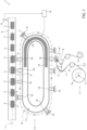
Figure 1 is a schematic top view, with parts removed for clarity, of a tag applicator device according to the present invention; -
Figure 2 is a larger-scale, schematic, partially sectioned side view, with parts removed for clarity, of a first preferred embodiment of a gripper member of the applicator device; -
Figure 3 is a larger-scale, schematic, partially sectioned side view, with parts removed for clarity, of a second preferred embodiment of the gripper member of the applicator device; -
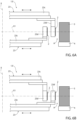
Figures 4a-4b are schematic top view, with parts removed for clarity, of a tag applicator device according to an alternative embodiment of the present invention; -
Figure 5 is a schematic top view, with parts removed for clarity, of a tag applicator device according to a further alternative embodiment of the present invention; and -
Figures 6a and 6b are schematic side views, with parts removed for clarity, of part of the tag applicator ofFigure 5 , during two distinct operative conditions. - With reference to
Figure 1 ,number 1 indicates as a whole a tag applicator device for applyingtags 2 ontopackages 3 containing a pourable product, preferably a pourable food product such as pasteurized or UHT milk, water, fruit juice, wine, peas, beans, etc. - In particular,
applicator device 1 is part of a packaging line (known per se and not shown) configured for producing a plurality ofsuch packages 3 in a known manner, starting from a tube (not shown) of packaging material. - More in particular, the packaging line comprises a packaging machine configured for forming, sealing and
folding packages 3 starting from such tube. - To this end, the packaging machine comprises:
- a filling device (not shown) for filling the tube with the pourable product;
- a forming and sealing device (not shown) for forming and sealing the tube, thereby obtaining a plurality of pillow packs, according to a manner known and not described in detail; and
- a folding device (not shown) for folding the pillow packs, thereby obtaining said
packages 3, according to a manner known and not described in detail. - Hence, the packaging machine is configured to form and seal a plurality of pillow packs containing the pourable product starting from the tube and then to fold the pillow packs for obtaining the aforementioned formed, sealed and folded
packages 3 containing the pourable product. - Preferably, the packaging material has a multilayer structure (not shown), and comprises a layer of fibrous material, e.g. paper, covered on both sides with respective layers of heat-seal plastic material, e.g. polyethylene.
- In the case of
aseptic packages 3 for long-storage products, such as UHT milk, the packaging material also comprises a layer of gas-and-light barrier material, e.g. aluminum foil or ethylene vinyl alcohol (EVOH) film, which is superimposed on a layer of heat-seal plastic material, and is in turn covered with another layer of heat-seal plastic material, the latter forming the inner face ofpackage 3 eventually contacting the pourable product. - Preferably, without however losing generality,
applicator device 1 is configured to apply ontopackages 3tags 2 of the informative type, such as QR-code tags (i.e. tags onto which a QR-code is printed), RFID tags, tags provided with a temperature sensor, or the like. - Since
tags 2 are applied to the finishedpackages 3,applicator device 1 is opportunely arranged operatively downstream of the folding device. -
Applicator device 1 may comprise one or more of: - a conveyor, preferably a
belt conveyor 4, configured for advancing a sequence ofpackages 3 along a conveying path L, in particular a sequence ofpackages 3 which are fed from the folding device; and - a
feeder 5 configured for feeding aweb 6 of labelling material along a feed path P. -
Web 6 comprises a longitudinal sequence oftags 2, i.e. a plurality oftags 2 arranged along the longitudinal direction ofweb 6. - More precisely,
web 6 comprises, in particular is defined by, a support strip on which a longitudinal sequence oftags 2 is initially attached to. - Hence, tags 2 are preferably defined by pieces of labelling material of the self-adhesive type.
- In light of the foregoing,
conveyor 4 is conveniently arranged downstream of the folding device for receivingpackages 3 therefrom. - As schematically shown in
Figure 1 ,feeder 5 includes: - a support unit, preferably a
support shaft 7 for supportingweb 6 in an unwindable manner, the web being initially provided in areel 7a wound aboutshaft 7; - a
feed roller 8, for feeding and/or advancingweb 6 along feed path P; - a plurality of
guide rollers 10 distributed along feed path P for supportingweb 6 along feed path P; and - a
deflector plate 11 for deviatingtags 2 from the support strip and off the feed path P, thereby causing the detachment of eachtag 2 from the support strip itself. - In particular,
deflector plate 11 defines a very narrow angle of feed path P, which obligesweb 6 to make a very narrow turn, thereby causingtags 2 to detach from the support strip. - Conveniently,
feeder 5 further comprises acollection roller 12 for collecting the spentweb 6, i.e. for collecting the support strip downstream ofdeflector plate 11 from which tags 2 have been already detached. - According to an aspect of the present invention,
applicator device 1 comprises atransfer device 13, e.g. operatively interposed betweenfeeder 5 andconveyor 4. Thetransfer device 13 is configured to sequentially receive tags 2 (from feeder 5) at a receiving station R, to transfertags 2 toconveyor 4 at an application station A, and to applytags 2 ontopackages 3, respectively, at application station A. - In particular, receiving station R is operatively interposed between
transfer device 13 andfeeder 5, namely is operatively shared by these latter. Similarly, application station A is operatively interposed betweentransfer device 13 andconveyor 4, namely is operatively shared by these latter. -
Transfer device 13 includes at least onegripper member 14 for retaining at least onetag 2 at a time. - In detail,
gripper member 14 is cyclically movable between receiving station R, at which it receives atag 2, and application station A, at which it releasessuch tag 2 onto onerespective package 3. -
Transfer device 13 is arranged adjacent to bothfeeder 5 andconveyor 4. - More precisely,
deflector plate 11 is located at receiving station R, for cyclically supplyinggripper member 14 with onedetached tag 2 at a time, and application station A is arranged along conveying path L, so that eachtag 2 is transferred to onerespective package 3. - According to a further aspect of the present invention,
applicator device 1 further comprises: - a
sensor 15 arranged adjacent to conveying path L, and in particular adjacent toconveyor 4, in a position operatively upstream of application station A, and configured to detect the presence ofpackages 3 along conveying path L and to generate a signal correlated to the detection; and - a
control unit 16 configured to receive said signal and to control the movement ofgripper member 14 based on said detection. - More specifically,
sensor 15 is configured to determine a package succession information along conveying path L based on said detection. - Accordingly,
control unit 16 is configured to control the movement ofgripper member 14 between receiving station R and application station A based on said package succession information. - Advantageously, according to the preferred embodiment shown in
Figure 1 ,transfer device 13 comprises: - an
endless track 17, in particular extending through receiving station R and application station A; - a plurality of
carts 18 movably coupled to track 17 and movable alongtrack 17 independently from one another, cyclically through receiving station R and application station A; and - a plurality of said
gripper members 14, eachgripper member 14 being carried by onerespective cart 18. - In detail,
carts 18 are movable along a closed-loop advancing path Q. - In one embodiment,
carts 18 andtrack 17 define a rail-slide coupling. - In one alternative embodiment,
carts 18 levitate with respect to track 17. - Preferably,
transfer device 13 comprises a linear motor actuator configured for driving the movement ofcarts 18 along path Q. - In greater detail, the linear motor actuator includes a plurality of electrically powerable solenoids (not shown) distributed along
track 17 and a plurality of permanent magnets (not shown), each one carried by a cart 18 (e.g. embedded in cart 18) and configured to magnetically interact with the solenoids for producing the movement of therespective cart 18. - In this way, an independent movement of
carts 18, and therefore ofgripper members 14, alongtrack 17 and path Q can be obtained. - Moreover, the use of a linear motor actuator and of
track 17 andcarts 18, allows for a largely improved flexibility in the control of such independent movement. - In fact, according to the invention,
control unit 16 is configured to adjust the advancement ofcarts 18, and therefore ofgripper members 14, alongtrack 17, i.e. towards receiving station R and application station A, based on the package succession information retrieved bysensor 15. - In this way, if a gap in the package succession along conveying path L and along
conveyor 4 occurs,carts 18 can be accordingly driven and thetags 2 retained by therespective gripper members 14 can be accordingly applied or not applied, based on the presence ofpackages 3 transiting at application station A in a given instant. - Moreover,
transfer device 13 according to the above, allows for a largely increased adaptability to a format change inpackages 3 and/ortags 2, and for a largely increased flexibility in case of a variation in the feeding pace ofpackages 3 byconveyor 4. -
Figures 2 and 3 illustrates acart 18 coupled to track 17 (in a movable manner), and agripper member 14 carried by, in particular mounted to,such cart 18. -
Gripper member 14 includes agripping wall 14a for retainingtags 2, preferably onetag 2 at a time. - As schematically shown in
Figure 2 , in oneembodiment gripping wall 14a is powerable, e.g. electrically energizable, for retainingtags 2 by electroadhesion. - More precisely, tags 2 are retained by each
gripper member 14 by means of an electrostatic force applied throughgripping wall 14a. - This configuration is particularly advantageous, since it provides for a highly reduced wear of
gripping wall 14a. Furthermore, the electroadhesion is characterized by a very good resistance to shear force, thereby limiting a mispositioning oftag 2 onto grippingwall 14a during the transfer from receiving station R to application station A (which occurs at high speed), while at the same time providing for little resistance to a peeling action (i.e. in a direction orthogonal to grippingwall 14a), thereby facilitating the release oftag 2 towards therespective package 3 at application station A. - In order to provide
gripping wall 14a with electrostatic energy,transfer device 13 further comprises an energizing portion, preferably an elongated energizingband 19, even more preferably fixed to track 17. The energizingband 19 extends along at least part of path Q. More specifically,band 19 extends at least at receiving station R and, optionally, at application station A, so thatgripping wall 14a receives energy at least at receiving station R and, optionally, at application station A. - Preferably,
band 19 extends between receiving station R and application station A. - More specifically,
band 19 extends from a position just upstream receiving station R to a position just upstream application station A. - That is,
band 19 may be located downstream of, and including, receiving station R and upstream of, and including or not including, application station A. - Advantageously,
band 19 is electrically connectable (e.g. directly or indirectly) to thegripping wall 14a of eachgripper member 14 for electrically poweringgripping walls 14a, e.g. between receiving station R and application station A. - In use, each
gripper member 14 cyclically transits throughband 19, thereby causing the respectivegripping wall 14a to be electrically connected (e.g. directly or indirectly) toband 19 and energized by this latter. - A
tag 2 can therefore be retained by electroadhesion. - Conveniently, each
gripper member 14 further comprises aconnection portion 20 configured to cyclically interact electrically withband 19 for receiving electric energy therefrom. - Advantageously, each
gripping wall 14a is powerable byband 19 by means of wireless power transfer. - In particular,
connection portion 20 is configured to electrically connect withband 19 wirelessly. - In this way, wear is further reduced. Moreover, complicated cabled connections can be avoided, which are not optimal in case of a
transfer device 13 withindependent carts 18 cyclically movable along anendless track 17. - As schematically shown in
Figure 3 , according to an alternative embodiment,gripper member 14 includes an electricallypowerable vacuum pump 21 andgripping wall 14a has at least onevacuum port 22 fluidly connected withvacuum pump 21 for retainingtags 2 by suction. - In this case,
band 19 is electrically connectable to thevacuum pump 21 of eachgripper member 14 for electrically powering vacuum pumps 21. - According to a preferred embodiment,
gripper wall 14a is equipped with a sucker cup (not shown) for better retaining thetag 2. Accordingly,band 19 may extend (e.g. only) at receiving station R and optionally at application station A, since the sucker cup retains thetag 2 even ifvacuum pump 21 is not powered. - According to an alternative embodiment,
band 19 extends between receiving station R and application station A, preferably from receiving station R to and including application station A. - In use, according to this embodiment, each
gripper member 14 cyclically transits throughband 19, thereby causing therespective vacuum pump 21 to be powered byband 19. - A
tag 2 can therefore be retained by suction through therespective port 22. - The Applicant has observed that this configuration provides for a stronger retaining force with respect to the electroadhesion, which is preferable for some formats, despite involving a slightly greater wear and more energy consumption.
- Also in this case, the
connection portion 20 may be powerable byband 19 by wireless power transfer. - This provides for reduced wear and allows to avoid cumbersome pneumatic and electric connections. Moreover, the total costs for maintenance are reduced.
- Preferably:
- each
cart 18 includes a cam follower (not shown) integrally fixed to the respectivegripping wall 14a, and -
track 17 includes at least one fixed cam surface (not shown) arranged application station A. - Advantageously, each cam follower is configured to cyclically interact with the cam surface at application station A for driving a (translating) movement of the respective
gripping wall 14a towardsconveyor 4 and conveying path L, so as to release therespective tag 2 on arespective package 3. - Such movement is schematized in
Figure 1 . - Conveniently, a further fixed cam surface is provided at receiving station R, for driving a movement of the respective
gripping wall 14a towardsfeeder 5 anddeflector plate 11, for receivingtags 2 therefrom. - This configuration allows for a better transfer of
tags 2 topackages 3 and for a better receiving oftags 2 fromfeeder 5, allowing at the same time for an increased flexibility of positioning oftransfer device 13 betweenconveyor 4 andfeeder 5, depending on the format ofpackages 3, oftags 2 and, in general, of the packaging line and the available space. - With reference to
Figures 4a-4b , number 13' indicates a transfer device according to an alternative embodiment of the present invention. Only the features of transfer device 13' which differs from the features oftransfer device 13 will be described in the following, using where possible the same reference numbers for similar or corresponding parts. - Transfer device 13' does not include a track and cart system as the one of
transfer device 13. - Instead, transfer device comprises an
arm 23 pivotably mounted about a fixed axis X and carrying at least one, preferably one, saidgripper member 14 at at least afree end 23a thereof. - In detail,
gripper member 14 is movably carried byarm 23. -
Arm 23 is arranged adjacent to bothfeeder 5 andconveyor 4, in particular adjacent to receiving station R and application station A. -
Arm 23 is rotatable about axis X, preferably in a reciprocal manner, for cyclically displacinggripper member 14 between receiving station R and application station A. - Accordingly,
Figure 4a showsarm 23 in a first position, withgripper member 14 at receiving station R for grasping atag 2 detached fromweb 6 bydeflector plate 11. -
Figure 4b showsarm 23 in a second position, withgripper member 14 at application station A for releasing and applyingtag 2 to arespective package 3 advanced byconveyor 4. - In practice,
arm 23 is configured to swing in an alternate manner between the first position and the second position, for carryinggripper member 14 at receiving station R and at application station A, cyclically. - In an alternative embodiment,
arm 23 is configured to rotate about axis X in a continuous manner (e.g. in a clockwise direction in theFigures 4a and 4b ). - In an alternative embodiment not shown,
arm 23 carries a pair ofgripper members 14 arranged at opposite free ends of thearm 23 itself. In this way, the rate of application of tags can be largely increased. - Advantageously, transfer device 13' comprises a pair of independently controllable actuators (not shown), for example electric or hydraulic or pneumatic actuators.
- More precisely, a first actuator of said pair of independently controllable actuators is activatable for controlling the reciprocating rotation of
arm 23 about axis X, and a second actuator of said pair of independently controllable actuators is activatable for controlling a translating movement ofgripper member 14 towards and away from axis X. - Hence, the first actuator and the second actuator are activatable, at the same time, to control a roto-translating movement of
gripper member 14 between receiving station R and application station A. - Moreover, transfer device 13' conveniently includes
sensor 15 andcontrol unit 16 as described above fortransfer device 13. - Thanks to this peculiar configuration, the trajectory of
gripper member 14 can be easily adjusted by means ofcontrol unit 16 activating the actuators in a combined manner based the package succession information retrieved bysensor 15. Flexibility and adaptability are thereby increased, as explained above. - Furthermore, while
transfer device 13 has a minimum pitch defined by the smallest possible physical distance between twoadjacent carts 18 ontrack 17, transfer device 13' has a minimum pitch which is virtually close to zero. To this purpose, in fact,applicator device 1 could comprise a plurality of transfer devices 13', i.e. a plurality ofarms 23 distributed in series alongconveyor 4. This would require a corresponding plurality offeeders 5, thereby defining various receiving stations R and various application stations A. This configuration allows for a high tag application rate. - In this direction,
Figure 5 shows a variation of transfer device 13' ofFigures 4a-4b . - More specifically, according to this variation, transfer device 13' comprises a plurality, e.g. a pair, of
arms 23, which are arranged coaxially to the common axis X and at different axial positions along axis X. - In other words, each
arm 23 is pivotally mounted about axis X and is rotatable about axis X in a reciprocal manner for displacing therespective gripper member 14 between receiving station R and application station A. - According to this embodiment, and as shown in
Figures 6a and 6b , eacharm 23 has alongitudinal portion 23c, extending orthogonally relative to axis X. -
Longitudinal portions 23c are arranged at different axial positions (or heights) with respect to axis X. - Each
longitudinal portion 23c carries onefree end 23a. - Each
arm 23 further comprises agripping portion 23d extending from the respectivelongitudinal portion 23d at thefree end 23a thereof, in a cantilevered manner. - Each gripping
portion 23d carries, in particular defines, onegripper member 14. - Advantageously, gripping
portions 23d of eacharm 23 extend towards a common axial height or coordinate X1, relative to axis X, so that thetags 2 retained thereby are arranged at the same axial height X1. - In a preferred embodiment, transfer device 13' comprises a pair of
arms 23. - As schematized in
Figures 6a and 6b , alower arm 23 of such pair ofarms 23 includes an upwardly extendinggripping portion 23d, whereas anupper arm 23 of such pair ofarms 23 includes a downwardly extendinggripping portion 23d. - The two
gripper members 14 defined by the twogripping portions 23d are located at the same axial position or height or coordinate X1, relative to axis X. - Moreover, as visible in
Figures 6a and 6b , the twoarms 23 exchange positions in an alternate manner, following the reciprocal motion described above and by means of the reciprocal rotation and the reciprocal translating movement. - In this way, tags 2 can be applied at the same position onto packages 3.
- Advantageously,
arms 23 are rotatable independently from one another about axis X. - In light of the above, movement of
arms 23, and therefore ofgripper members 14, can be controlled so that when afirst arm 23 is at receiving station R, asecond arm 23 is at application station A, thereby increasing the tag application rate and decreasing the minimum possible pitch between two successive tag applications. - Similar to what described above for
transfer device 13,gripper member 14 has agripping wall 14a and is configured to retaintag 2 by electroadhesion or by suction, in the same manner as described above. - From the foregoing, it is clear how
applicator device 1 according to the invention allows to implement a method for applying tags onto packages made of packaging material and containing a pourable product, the method comprising the steps of: - advancing a plurality of packages along a conveying path;
- detecting the presence of packages along the conveying path;
- determining a package succession information along the conveying path by the step of detecting;
- feeding a web of labelling material along a feed path, the web comprising a longitudinal sequence of tags;
- sequentially withdrawing the tags from the web at a receiving station by means of one or more gripper members;
- transferring the tags from the receiving station to an application station at which the tags are applied onto respective packages;
- determining a motion profile of the one or more gripper members based on the determined package succession information; and
- controlling a movement of the one or more grippers between the receiving station and the application station with said motion profile.
- The advantages of
applicator device 1 according to the present invention will be clear from the foregoing description. - In particular, if a gap in the succession of
packages 3 along conveying path L and alongconveyor 4 occurs, gripper member(s) 14 can be accordingly driven and thetags 2 retained by this(these) latter can be accordingly applied or not applied, based on the presence ofpackages 3 transiting at application station A in a given instant. - Moreover, the present invention allows for a largely increased adaptability to a format change in
packages 3 and/ortags 2, and for a largely increased flexibility in case of a variation in the feeding pace ofpackages 3 byconveyor 4. - Clearly, changes may be made to
applicator device 1 as described herein without, however, departing from the scope of protection as defined in the accompanying claims.
Claims (16)
- Tag applicator device (1) for a packaging line configured for producing packages (3) containing a pourable product, the applicator device (1) comprising a transfer device (13; 13') configured to sequentially receive tags (2) from a feeder (5) at a receiving station (R) and to apply the tags (2) onto the packages (3) at the application station (A), the sequence of packages (3) advancing along a conveying path (L);wherein the transfer device (13; 13') includes at least one gripper member (14) for retaining at least one tag (2) at a time, the gripper member (14) being cyclically movable between the receiving station (R), at which it receives a tag (2), and the application station (A), at which it applies the tag (2) onto one respective package (3);and wherein the applicator device (1) is configured so that the cyclical movement of the gripper member (14) between the receiving station (R) and the application station (A) is synchronized with the advancement of the packages (3) along the conveying path (L).
- Applicator device as claimed in claim 1, and further comprising:- a sensor (15) arranged adjacent to the conveying path (L) in a position operatively upstream of the application station (A) and configured to detect a presence of packages (3) along the conveying path (L) and to generate a signal correlated to the detection; and- a control unit (16) configured to receive said signal and to control the movement of the gripper member (14) based on said detection.
- Applicator device as claimed in claim 2, wherein the sensor (15) is configured to determine a package succession information along the conveying path (L) based on said detection;
and wherein the control unit (16) is configured to control the movement of the gripper member (14) between the receiving station (R) and the application station (A) based on said package succession information. - Applicator device as claimed in any one of the foregoing claims, wherein the gripper member (14) includes a gripping wall (14a) for retaining the tags (2) by electroadhesion.
- Applicator device as claimed in any of the claims 1 to 3, wherein the gripper member (14) includes:- a vacuum pump (21);- a gripping wall (14a) for retaining the tags (2) and having at least one vacuum port (22) fluidly connected with the vacuum pump (21) for retaining the tags (2) by suction.
- Applicator device as claimed in any one of the foregoing claims, wherein the transfer device (13) comprises:- an endless track (17);- a plurality of carts (18) movably coupled to the track (17) and movable along the track (17) independently from one another, cyclically through the receiving station (R) and the application station (A); and- a plurality of said gripper members (14), each gripper member (14) being carried by one respective cart (18).
- Applicator device as claimed in claims 4 and 6, wherein the carts (18) are movable along a closed-loop advancing path (Q);wherein the transfer device (13) further comprises an energizing portion (19) extending along at least part of the advancing path (Q), preferably at the receiving station (R),and wherein the energizing portion (19) is configured to power the gripping wall (14a) of each gripper member (14).
- Applicator device as claimed in claim 7, wherein the energizing portion (19) is configured to power each gripping wall (14a) by means of wireless power transfer.
- Applicator device as claimed in claims 5 and 6, wherein the carts (18) are movable along a closed-loop advancing path (Q);wherein the transfer device (13) further comprises an energizing portion (19) arranged along at least part of the advancing path (Q),and wherein the energizing portion (19) is configured to power the vacuum pump (21) of each gripper member (14).
- Applicator device as claimed in any one of the claims 6 to 9, wherein the transfer device (13) comprises a linear motor actuator for driving the movement of said carts (18),
the linear motor actuator including a plurality of electrically powerable solenoids distributed along the track (17) and a plurality of permanent magnets, each permanent magnet being carried by a cart (18) and being configured to magnetically interact with the solenoids for producing the movement of the respective cart (18) along the track (17). - Applicator device as claimed in any one of the claims 1 to 5, wherein the transfer device (13') comprises an arm (23) pivotably mounted about a fixed axis (X) and carrying at least one said gripper member (14) at at least a free end (23a) thereof;
the arm (23) being rotatable about said axis (X) for cyclically displacing the gripper member (14) between the receiving station (R) and the application station (A). - Applicator device as claimed in claim 11, wherein the transfer device (13') comprises a pair of independently controllable actuators,a first actuator being activatable for controlling the rotation of the arm (23),a second actuator being activatable for controlling a translating movement of the gripper member (14) towards and away from said axis (X);the first actuator and the second actuator being activatable to control a roto-translating movement of the gripper member (14) between the receiving station (R) and the application station (A).
- Applicator device as claimed in claim 11 or 12, wherein the transfer device (13') comprises a plurality of said arms (23) which are arranged coaxially and at different axial positions along said axis (X),
said arms (23) being rotatable independently from one another about said axis (X). - Applicator device as claimed in claim 13, wherein each arm (23) comprises:- a longitudinal portion (23c) extending transversally with respect to said axis (X) and carrying one said free end (23a); and- a gripping portion (23d) carrying one said gripper member (14) and extending from the longitudinal portion (23c) at said free end (23a) in a cantilevered manner and towards a common axial height (X1) or coordinate, relative to said axis (X), so that the tags (2) retained thereby are arranged at the same axial height (X1).
- Packaging line configured for forming, sealing and folding packages (3) containing a pourable product starting from a tube of packaging material, the packaging line comprising:- a filling device for filling the tube with the pourable product;- a forming and sealing device for forming and sealing the tube, thereby obtaining a plurality of pillow packs;- a folding device for folding the pillow packs, thereby obtaining said packages (3);- a conveyor (4) for advancing a sequence of packages (3) received from the folding device along a conveying path (L) ;- a feeder (5) configured for feeding a web (6) of labelling material along a feed path (P), the web (6) comprising a longitudinal sequence of tags (2); and- an applicator device (1) as claimed in any one of the foregoing claims,.
- Method for applying tags (2) onto packages (3) made of packaging material and containing a pourable product, the method comprising the steps of:- advancing a plurality of packages (3) along an conveying path (L);- detecting the presence of packages (3) along the conveying path (L);- determining a package succession information along the conveying path (L) by the step of detecting;- feeding a web (6) of labelling material along a feed path (L), the web (6) comprising a longitudinal sequence of tags (2);- sequentially withdrawing the tags (2) from the web (6) at a receiving station (R) by means of one or more gripper members (14);- transferring the tags (2) from the receiving station (R) to an application station (A) at which the tags (2) are applied onto respective packages (3);and wherein the method further comprises the steps of:- determining a motion profile of the one or more gripper members (14) based on the determined package succession information; and- controlling a movement of the one or more gripper members (14) between the receiving station (R) and the application station (A) with said motion profile.
Applications Claiming Priority (1)
| Application Number | Priority Date | Filing Date | Title |
|---|---|---|---|
| IT102023000002010A IT202300002010A1 (en) | 2023-02-07 | 2023-02-07 | TAG APPLICATOR DEVICE FOR A PACKAGING MACHINE CONFIGURED TO FORM, SEAL AND FOLD A MULTIPLE PACKAGES CONTAINING A POURABLE PRODUCT |
Publications (1)
| Publication Number | Publication Date |
|---|---|
| EP4414277A1 true EP4414277A1 (en) | 2024-08-14 |
Family
ID=85937057
Family Applications (1)
| Application Number | Title | Priority Date | Filing Date |
|---|---|---|---|
| EP24154605.0A Pending EP4414277A1 (en) | 2023-02-07 | 2024-01-30 | Tag applicator device for a packaging line configured for forming, sealing and folding a plurality of packages containing a pourable product |
Country Status (3)
| Country | Link |
|---|---|
| EP (1) | EP4414277A1 (en) |
| IT (1) | IT202300002010A1 (en) |
| WO (1) | WO2024165373A1 (en) |
Families Citing this family (1)
| Publication number | Priority date | Publication date | Assignee | Title |
|---|---|---|---|---|
| DE102024105456A1 (en) * | 2024-02-27 | 2025-08-28 | Krones Aktiengesellschaft | Labeling machine for labeling containers |
Citations (5)
| Publication number | Priority date | Publication date | Assignee | Title |
|---|---|---|---|---|
| WO2007114752A1 (en) | 2006-03-31 | 2007-10-11 | Tetra Laval Holdings & Finance S.A. | Forming device, machine, packaging laminate web, forming method and process in producing packages |
| WO2009146191A2 (en) * | 2008-04-17 | 2009-12-03 | Hurst International, Llc | Method and apparatus for high speed produce labeling |
| DE102014119391B3 (en) * | 2014-12-22 | 2015-12-17 | Espera-Werke Gmbh | Device and method for labeling individual packages |
| WO2017001076A1 (en) * | 2015-06-30 | 2017-01-05 | Krones Ag | Apparatus and method for labelling containers |
| WO2018202320A1 (en) * | 2017-05-02 | 2018-11-08 | Sidel Participations | A labelling machine for applying label sheets onto articles |
-
2023
- 2023-02-07 IT IT102023000002010A patent/IT202300002010A1/en unknown
-
2024
- 2024-01-30 WO PCT/EP2024/052147 patent/WO2024165373A1/en not_active Ceased
- 2024-01-30 EP EP24154605.0A patent/EP4414277A1/en active Pending
Patent Citations (5)
| Publication number | Priority date | Publication date | Assignee | Title |
|---|---|---|---|---|
| WO2007114752A1 (en) | 2006-03-31 | 2007-10-11 | Tetra Laval Holdings & Finance S.A. | Forming device, machine, packaging laminate web, forming method and process in producing packages |
| WO2009146191A2 (en) * | 2008-04-17 | 2009-12-03 | Hurst International, Llc | Method and apparatus for high speed produce labeling |
| DE102014119391B3 (en) * | 2014-12-22 | 2015-12-17 | Espera-Werke Gmbh | Device and method for labeling individual packages |
| WO2017001076A1 (en) * | 2015-06-30 | 2017-01-05 | Krones Ag | Apparatus and method for labelling containers |
| WO2018202320A1 (en) * | 2017-05-02 | 2018-11-08 | Sidel Participations | A labelling machine for applying label sheets onto articles |
Also Published As
| Publication number | Publication date |
|---|---|
| WO2024165373A1 (en) | 2024-08-15 |
| IT202300002010A1 (en) | 2024-08-07 |
Similar Documents
| Publication | Publication Date | Title |
|---|---|---|
| US9403611B2 (en) | Unit for sequencing and guiding items | |
| EP2193084B1 (en) | Device and method for filling of a container | |
| EP2291311B1 (en) | Device for filling of containers | |
| WO2024165373A1 (en) | Tag applicator device for a packaging line configured for forming, sealing and folding a plurality of packages containing a pourable product | |
| EP4303019B1 (en) | Digital printing apparatus for a packaging machnine and packaging machine having a digital printing apparatus | |
| EP4549328A2 (en) | A device for performing operations on a packaging material for the production of packages containing a pourable product and related method | |
| RU2741650C1 (en) | Filling machine for filling of flexible package of bag type | |
| EP4495018B1 (en) | Cap applicator system for a packaging machine and method for applying caps | |
| CN114364609A (en) | Device and method for placing a handle on a packaging material or a group of packaging materials | |
| RU2272759C2 (en) | Liquid food packing machine and method to control auxiliary means position on web | |
| EP4480870A1 (en) | Conveyor device for a packaging machine and packaging machine | |
| EP1789351B1 (en) | Apparatus for feeding pouches and their respective spouts to a rotary machine for the processing of the same and relative method | |
| CN224225469U (en) | Conveying structure for packaging bags | |
| EP4140902A1 (en) | Labelling machine for applying labels onto containers adapted to contain a pourable product | |
| HK1077791B (en) | A forming unit for producing sealed packages from a tube of sheet packaging material | |
| HK1077791A1 (en) | A forming unit for producing sealed packages from a tube of sheet packaging material | |
| HK1144274B (en) | Device and method for filling of a container |
Legal Events
| Date | Code | Title | Description |
|---|---|---|---|
| PUAI | Public reference made under article 153(3) epc to a published international application that has entered the european phase |
Free format text: ORIGINAL CODE: 0009012 |
|
| STAA | Information on the status of an ep patent application or granted ep patent |
Free format text: STATUS: THE APPLICATION HAS BEEN PUBLISHED |
|
| AK | Designated contracting states |
Kind code of ref document: A1 Designated state(s): AL AT BE BG CH CY CZ DE DK EE ES FI FR GB GR HR HU IE IS IT LI LT LU LV MC ME MK MT NL NO PL PT RO RS SE SI SK SM TR |
|
| STAA | Information on the status of an ep patent application or granted ep patent |
Free format text: STATUS: REQUEST FOR EXAMINATION WAS MADE |
|
| 17P | Request for examination filed |
Effective date: 20250214 |