EP4414254A1 - Safe start control device for chainless electric bicycle and control method therefor - Google Patents
Safe start control device for chainless electric bicycle and control method therefor Download PDFInfo
- Publication number
- EP4414254A1 EP4414254A1 EP23184418.4A EP23184418A EP4414254A1 EP 4414254 A1 EP4414254 A1 EP 4414254A1 EP 23184418 A EP23184418 A EP 23184418A EP 4414254 A1 EP4414254 A1 EP 4414254A1
- Authority
- EP
- European Patent Office
- Prior art keywords
- drive wheel
- standby mode
- state
- drive
- drive controller
- Prior art date
- Legal status (The legal status is an assumption and is not a legal conclusion. Google has not performed a legal analysis and makes no representation as to the accuracy of the status listed.)
- Granted
Links
Images


Classifications
-
- B—PERFORMING OPERATIONS; TRANSPORTING
- B62—LAND VEHICLES FOR TRAVELLING OTHERWISE THAN ON RAILS
- B62J—CYCLE SADDLES OR SEATS; AUXILIARY DEVICES OR ACCESSORIES SPECIALLY ADAPTED TO CYCLES AND NOT OTHERWISE PROVIDED FOR, e.g. ARTICLE CARRIERS OR CYCLE PROTECTORS
- B62J27/00—Safety equipment
-
- B—PERFORMING OPERATIONS; TRANSPORTING
- B62—LAND VEHICLES FOR TRAVELLING OTHERWISE THAN ON RAILS
- B62M—RIDER PROPULSION OF WHEELED VEHICLES OR SLEDGES; POWERED PROPULSION OF SLEDGES OR SINGLE-TRACK CYCLES; TRANSMISSIONS SPECIALLY ADAPTED FOR SUCH VEHICLES
- B62M6/00—Rider propulsion of wheeled vehicles with additional source of power, e.g. combustion engine or electric motor
- B62M6/40—Rider propelled cycles with auxiliary electric motor
- B62M6/45—Control or actuating devices therefor
-
- B—PERFORMING OPERATIONS; TRANSPORTING
- B60—VEHICLES IN GENERAL
- B60L—PROPULSION OF ELECTRICALLY-PROPELLED VEHICLES; SUPPLYING ELECTRIC POWER FOR AUXILIARY EQUIPMENT OF ELECTRICALLY-PROPELLED VEHICLES; ELECTRODYNAMIC BRAKE SYSTEMS FOR VEHICLES IN GENERAL; MAGNETIC SUSPENSION OR LEVITATION FOR VEHICLES; MONITORING OPERATING VARIABLES OF ELECTRICALLY-PROPELLED VEHICLES; ELECTRIC SAFETY DEVICES FOR ELECTRICALLY-PROPELLED VEHICLES
- B60L15/00—Methods, circuits, or devices for controlling the traction-motor speed of electrically-propelled vehicles
- B60L15/20—Methods, circuits, or devices for controlling the traction-motor speed of electrically-propelled vehicles for control of the vehicle or its driving motor to achieve a desired performance, e.g. speed, torque, programmed variation of speed
-
- B—PERFORMING OPERATIONS; TRANSPORTING
- B62—LAND VEHICLES FOR TRAVELLING OTHERWISE THAN ON RAILS
- B62J—CYCLE SADDLES OR SEATS; AUXILIARY DEVICES OR ACCESSORIES SPECIALLY ADAPTED TO CYCLES AND NOT OTHERWISE PROVIDED FOR, e.g. ARTICLE CARRIERS OR CYCLE PROTECTORS
- B62J45/00—Electrical equipment arrangements specially adapted for use as accessories on cycles, not otherwise provided for
- B62J45/40—Sensor arrangements; Mounting thereof
- B62J45/41—Sensor arrangements; Mounting thereof characterised by the type of sensor
-
- B—PERFORMING OPERATIONS; TRANSPORTING
- B62—LAND VEHICLES FOR TRAVELLING OTHERWISE THAN ON RAILS
- B62M—RIDER PROPULSION OF WHEELED VEHICLES OR SLEDGES; POWERED PROPULSION OF SLEDGES OR SINGLE-TRACK CYCLES; TRANSMISSIONS SPECIALLY ADAPTED FOR SUCH VEHICLES
- B62M6/00—Rider propulsion of wheeled vehicles with additional source of power, e.g. combustion engine or electric motor
- B62M6/40—Rider propelled cycles with auxiliary electric motor
- B62M6/45—Control or actuating devices therefor
- B62M6/50—Control or actuating devices therefor characterised by detectors or sensors, or arrangement thereof
-
- B—PERFORMING OPERATIONS; TRANSPORTING
- B60—VEHICLES IN GENERAL
- B60L—PROPULSION OF ELECTRICALLY-PROPELLED VEHICLES; SUPPLYING ELECTRIC POWER FOR AUXILIARY EQUIPMENT OF ELECTRICALLY-PROPELLED VEHICLES; ELECTRODYNAMIC BRAKE SYSTEMS FOR VEHICLES IN GENERAL; MAGNETIC SUSPENSION OR LEVITATION FOR VEHICLES; MONITORING OPERATING VARIABLES OF ELECTRICALLY-PROPELLED VEHICLES; ELECTRIC SAFETY DEVICES FOR ELECTRICALLY-PROPELLED VEHICLES
- B60L2260/00—Operating Modes
- B60L2260/20—Drive modes; Transition between modes
-
- B—PERFORMING OPERATIONS; TRANSPORTING
- B62—LAND VEHICLES FOR TRAVELLING OTHERWISE THAN ON RAILS
- B62M—RIDER PROPULSION OF WHEELED VEHICLES OR SLEDGES; POWERED PROPULSION OF SLEDGES OR SINGLE-TRACK CYCLES; TRANSMISSIONS SPECIALLY ADAPTED FOR SUCH VEHICLES
- B62M19/00—Transmissions characterised by use of non-mechanical gearing, e.g. fluid gearing
Definitions
- the present invention relates to a safe start control device for a chainless electric bicycle and a control method therefor, and in particular, a safe start control device for a chainless electric bicycle and a control method therefor capable of promoting rider's safety by preventing an unintended start state even when a pedal input is inadvertently generated due to a rider's repetitive getting on and off operation in a drivable state where power of a chainless electric bicycle for delivery is turned on.
- An electric bicycle turns a motor with electricity to assist a person or to drive a bicycle.
- a method in which the power of a motor is used to assist a person stepping on a pedal to drive wheels is called a pedal assistance system (PAS) method, and a method in which a pedal and a drive motor are only electronically connected therebetween without chain connection is called a series hybrid method.
- PAS pedal assistance system
- the hybrid method can be controlled in various ways by software, so a motor of an electric bicycle can be driven with much less pedal force than the PAS method.
- Chainless electric bicycles for delivery can move the bicycle even when carrying a heavy load of 100 kg or more, and have an advantage of being able to start and move easily with just the rider's pedal input.
- an electronic control system inside the chainless electric bicycle can drive the motor with energy stored in a battery regardless of the strength of the rider's legs when an input to a generator connected to the rider's pedal is received only as an electrical signal.
- the present invention provides a safe start control device for a chainless electric bicycle in accordance with claim 1, a safe start control device for a chainless electric bicycle in accordance with claim 5, a method in accordance with claim 9, and a method in accordance with claim 13.
- a safe start control device for a chainless electric bicycle includes a wheel sensor configured to detect a speed of a drive wheel; a drive controller configured to determine that the drive wheel is in a stopped state if the detected speed of the drive wheel satisfies a preset reference value, to initialize a stop timer, and to switch to a driving standby mode state when a preset stop timer time elapses; and a driving mode changeover input unit configured to receive a driving standby mode release signal from a rider in the driving standby mode state, in which the drive controller is configured to switch to a drivable mode state when the driving standby mode release signal is input to the driving mode changeover input unit.
- the driving mode changeover input unit is configured by a brake lever or a mode changeover switch.
- the drive controller when the brake lever is operated, e.g., pressed or pulled, for a preset time or longer, the drive controller is switched to the drivable mode state.
- the drive controller when a driving standby mode release state is input to the mode changeover switch, the drive controller is switched to the drivable mode state.
- the drive controller is configured to control the drive wheel not to be driven when a pedal input is applied in the driving standby mode state.
- the drive controller may control a motor coupled to the drive wheel to be prevented from outputting torque to the drive wheel in the driving standby mode state.
- the drive controller is configured, when the detected speed of the drive wheel satisfies a value of 0 Km/h, to determine that the drive wheel is in a stopped state.
- a safe start control device for a chainless electric bicycle includes a wheel sensor configured to detect a speed of a drive wheel; a drive controller configured to determine that the drive wheel is in a stopped state if the detected speed of the drive wheel satisfies a preset reference value, to initialize a stop timer, and to switch to a driving standby mode state when a preset stop timer time elapses; and a communication module configured to be linked with a mobile terminal of a rider and to receive a driving standby mode release signal from the rider, in which the drive controller is configured to switch to a drivable mode state when the driving standby mode release signal is received by the communication module.
- the communication module may be configured to establish a signal communication with the mobile terminal of the rider when the mobile terminal comes close to the communication module within a predetermined distance range, so that the mobile terminal and the communication module are linked with each other, and hwerein the drive controller is configured to switch to a drivable mode state input to the mobile terminal of the rider upon linking of the communication module with the mobile terminal.
- a driving mode changeover control application may be installed on the mobile terminal of the rider. The application may be configured to receive an input from the rider indicating that switching to the drivable mode state is desired. The input causes the mobile terminal to issue a switching signal which is received by the communication module linked with the mobile terminal.
- the drive controller is configured to control the drive wheel not to be driven when a pedal input is applied in the driving standby mode state.
- the drive controller may control a motor coupled to the drive wheel to be prevented from outputting torque to the drive wheel in the driving standby mode state.
- the communication module uses, a Bluetooth module, a Wifi module, a Jigbee module, a UWB module, a Cellular communication module, or an NFC module.
- the drive controller is configured, when the detected speed of the drive wheel satisfies a value of 0 Km/h, to determine that the drive wheel is in a stopped state.
- a safe start control method for a chainless electric bicycle that includes a drive device of the chainless electric bicycle being in a powered-on and drivable state, includes detecting, by a wheel sensor, a speed of a drive wheel; determining, by a drive controller, whether the drive wheel is in a stopped state by comparing the detected speed of the drive wheel with a preset reference value; initializing, by the drive controller, a stop timer if it is determined that the drive wheel is in the stopped state; switching to a driving standby mode state when a preset stop timer time elapses after the initialization by the drive controller; and switching to a drivable mode state when a driving standby mode release signal is received from a rider in the driving standby mode state.
- the method of this aspect of the invention may be carried out using the device of the first aspect of the invention.
- the driving standby mode release signal is received from a brake lever or a mode changeover switch.
- the brake lever when operated, e.g., pulled or pressed, for a preset time or longer, the switching to the drivable mode state is performed.
- the drive controller is configured to control the drive wheel not to be driven when a pedal input is applied in the driving standby mode state.
- the drive controller may control a motor coupled to the drive wheel to be prevented from outputting torque to the drive wheel in the driving standby mode state.
- the drive wheel in the determination as to whether the drive wheel is in the stopped state, when the detected speed of the drive wheel satisfies a value of 0 Km/h, the drive wheel is determined as being in the stopped state.
- a safe start control method for a chainless electric bicycle that includes a drive device being in a powered-on and drivable state, includes detecting, by a wheel sensor, a speed of a drive wheel; determining, by a drive controller, whether the drive wheel is in a stopped state by comparing the detected speed of the drive wheel with a preset reference value; initializing, by the drive controller, a stop timer if it is determined that the drive wheel is in the stopped state; switching to a driving standby mode state when a preset stop timer time elapses after the initialization by the drive controller; and switching to a drivable mode state when a mobile terminal of a rider and a communication module are linked with each other and a driving standby mode release signal is received from the rider.
- the method of this aspect of the invention may be carried out using the device of the second aspect of the invention.
- the drive controller is configured to control the drive wheel not to be driven when a pedal input is applied in the driving standby mode state.
- the communication module uses a Bluetooth module, a Wifi module, a Jigbee module, a UWB module, a Cellular communication module, or an NFC module.
- the drive wheel in the determination as to whether the drive wheel is in a stopped state, when the detected speed of the drive wheel satisfies a value of 0 Km/h, the drive wheel is determined as being in a stopped state.
- a drive controller is enabled to be switched to a driving standby mode when it is detected that a drive wheel is in a stopped state for a predetermined time.
- the drive controller according to the invention, is switched from the driving standby mode to a drivable mode state a driving standby upon receiving mode release signal.
- This mode release signal is input via a driving mode changeover input unit.
- the driving standby mode release signal is received from an external source, e.g., from a mobile terminal, via a communication module.
- a part is “connected” to another part, this includes not only the case of being “directly connected” but also the case of being “electrically connected” with another element therebetween.
- a part includes” another component, it means that the part may further include other components, not excluding other components unless otherwise stated, and it should be understood that the presence or addition of one or more other features, numbers, steps, operations, components, parts, or combinations thereof are not precluded.
- 'unit' or 'module' includes a unit realized by hardware or software, or a unit realized by using both the hardware and the software, and one unit may be realized by using two or more hardware, or two or more units may be realized by one hardware.
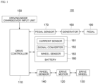
- FIG. 1 is a diagram schematically showing an overall configuration of a chainless electric bicycle according to an exemplary embodiment of the present invention
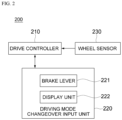
- FIG. 2 is a diagram schematically showing a configuration of a safety start control device for a chainless electric bicycle according to a first exemplary embodiment of the present invention
- FIG. 3 is a diagram schematically showing a configuration of a safety start control device for a chainless electric bicycle according to a second exemplary embodiment of the present invention
- FIG. 4 is a diagram schematically showing a configuration of a safety start control device for a chainless electric bicycle according to a third exemplary embodiment of the present invention.
- a chainless electric bicycle 100 may include a drive controller 110, a drive motor 120, a drive wheel 130, a wheel sensor 140, a driving mode changeover input unit 150, a generator 160, a pedal sensor 170, a battery 180, and a pedal 190.
- the chainless electric bicycle may be a chainless electric bicycle for delivery and may include four drive wheels, but is not limited thereto.
- the drive controller 110 generates current for driving the drive motor 120 based on a position and/or speed of the pedal 190 and a position and/or speed of the drive wheel 130.
- the drive controller 110 may include one or more processors and memories.
- the electric bicycle controls the motor so that the speed increases as the speed or torque of the pedal increases.
- the drive controller 110 generates current for controlling the motor based on a difference between the position or speed of the pedal 190 and the position or speed of the drive wheel 130.
- the drive controller calculates a current for drive using a difference between the speed of the pedal 190 and the speed of the drive motor 120 connected to the drive wheel 130.
- the same gear ratio as that of a general bicycle may be considered, and a degree of assistance of the drive motor may be considered according to a driving mode.
- the drive controller 110 may include at least a CPU and a memory.
- the drive controller 110 may further include an ADC (Analogue Digital Converter) in preparation for a case where an input signal is provided as an analog signal.
- the drive controller 110 may be implemented with a microcontroller, a microprocessor, a microcomputer, an ASIC chip, or the like.
- an application program in which a logic of the safe start control method described below is implemented is embedded in the memory.
- the CPU may execute the application program stored in the memory to perform a control for preventing an unintended start by stopping the drive of the drive motor 120 when it is predicted that an unintended start situation will occur while driving the drive motor 120.
- the drive controller 110 may determine a stopped state of the bicycle 100 by detecting the speed of the drive wheel 130 sensed by the wheel sensor 140 and may switch to a driving standby mode. In particular, the drive controller determines that the drive wheel is in a stopped state if the detected speed of the drive wheel 130 satisfies a preset reference value, initializes a stop timer, and controls to switch to a driving standby mode state when a preset stop timer time elapses. This will be described in further detail below.
- the drive motor 120 is connected to the drive wheel 130 and the drive controller 110 and supplies drive power to the drive wheel 130 under control of the drive controller 110.
- the drive wheel 130 may be electrically connected to a pedal and driven only by the drive motor 120.
- the wheel sensor 140 measures a position and/or a speed of the drive wheel 130.
- the driving mode changeover input unit 150 receives a driving standby mode release signal from a rider in the driving standby mode switched by the drive controller 110.
- the various embodiments thereof will be described in detail below.
- the generator 160 is connected to the pedal 190 to create a pedal load feeling similar to that of a bicycle including a chain, and can be controlled by classifying pedal feeling torque values for each torque region by the drive controller. For example, a speed at which a rider of a chainless electric bicycle turns a pedal is recognized to control the speed of the motor in proportion to the speed. No load is applied to the pedal because a chain is not connected to the pedal. Therefore, in order to create a pedal load feeling like a bicycle with a chain, the generator 160 connected to the pedal 190 is controlled accordingly. When the load of the pedal 190 is controlled according to the speed of the electric bicycle, the user feels a pedal feeling similar to that of a normal bicycle with a chain.
- the pedal sensor 170 measures a position or speed of the pedal for rotating the generator 160.
- the battery 180 serves as a main power source that supplies power necessary for driving the drive wheel 130 through the drive motor 120 and also supplies power to components requiring electricity, such as the drive controller 110 and the accelerator.
- the battery 180 may include a current sensor 181 that detects an amount of current supplied to the drive motor 120, a signal converter 182 that converts an analog signal of the detected amount of current into a digital signal, and a battery management system (BMS) 183 that is connected to the signal converter and calculates a value of instantaneous current applied to the motor based on the signal transmitted from the signal converter.
- BMS battery management system
- a safety start control device 200 for a chainless electric bicycle includes a drive controller 210, a driving mode changeover input unit 220, and a wheel sensor 230.
- the drive controller 210 determines that the drive wheel is in a stopped state if the speed of the drive wheel detected by the wheel sensor 230 satisfies a preset reference value, initializes a stop timer, and switches to a driving standby mode state when a preset stop timer time elapses.
- the drive controller 210 may determine that the drive wheel is in a stopped state when the speed of the drive wheel detected by the wheel sensor 230 satisfies a value of 0 Km/h. Then, the drive controller waits until a preset stop timer time is reached after initializing the stop timer. For example, when the stop timer time is set to 5 minutes, the drive controller is in the drivable state for 5 minutes, but after 5 minutes, switches to the driving standby mode. In this case, the drive controller 210 controls the drive wheel not to be driven when a pedal input is applied in the driving standby mode state. For example, the controller 210 may control the motor 120 to remain in a non-driving, stopped state in which the motor 120 outputs no torque to the drive wheel 130.
- an input to the generator connected to the rider's pedal may cause a sudden start of the bicycle, contrary to the intention of the rider.
- the drive controller 210 prevents the unintentional start by controlling the drive wheel not to be driven when a pedal input is applied in the driving standby mode state.
- the driving mode changeover input unit 220 receives a driving standby mode release signal from a rider in the driving standby mode state.
- the driving mode changeover input unit 220 may include a brake lever 221 and a display unit 222.
- the brake lever 221 can be used as an input unit for braking in a general driving mode, and can be applied to function as an input unit for releasing the driving standby mode.
- a rider's operation of gripping the brake lever 221 in the driving standby mode state can release the driving standby mode.
- the driving standby mode state is switched to a drivable mode state.
- the display unit 222 may display a driving speed and a driving mode changeover state of the chainless electric bicycle.
- the wheel sensor 230 detects the speed of the drive wheel of the chainless electric bicycle in a powered-on and drivable state.
- a safety start control device 300 of a chainless electric bicycle may include a drive controller 310, a driving mode changeover input unit 320, and a wheel sensor 330.
- a drive controller 310 may control the driving mode changeover input unit 320 and a wheel sensor 330.
- the driving mode changeover input unit 320 may include a mode changeover switch 321, a brake lever 322 and a display unit 323.
- the drive controller can be switched to the drivable mode state.
- the mode changeover switch 321 may be configured in a part of a rider operation unit of the chainless electric bicycle.
- the brake lever 322 can be used as an input unit for braking in a general driving mode, and the display unit 323 can display the driving speed and driving mode changeover state of the chainless electric bicycle.
- the safety start control device 400 for a chainless electric bicycle may include a drive controller 410, a communication module 420, a wheel sensor 430, a brake lever 440, and a display unit 450.
- a drive controller 410 the safety start control device 400 for a chainless electric bicycle
- a communication module 420 the safety start control device 400 for a chainless electric bicycle
- a wheel sensor 430 the safety start control device 400 for a chainless electric bicycle
- a brake lever 440 may include a display unit 450.
- the detailed description of the configurations described with reference to the first exemplary embodiment will be omitted.
- the communication module 420 may be configured to release the driving standby mode.
- the communication module 420 may be linked with a mobile terminal of a rider and receive a driving standby mode release signal from the rider.
- the communication module 420 may use a Bluetooth module or an NFC module, but is not limited thereto.
- a driving mode changeover control application is installed on the mobile terminal of the rider, and when the mobile terminal comes close to the communication module 420 of the chainless electric bicycle within a predetermined distance range, the mobile terminal and the communication module are linked with each other and the communication module 420 receives a driving standby mode release signal input to the mobile terminal by the rider.
- the drive controller 410 switches to the drivable mode state when the communication module 420 receives a driving standby mode release signal.
- FIG. 5 is a flowchart of a safe start control method for a chainless electric bicycle according to the first exemplary embodiment of the present invention.
- a safe start control method for a chainless electric bicycle includes performing a step (S510) of detecting, by a wheel sensor, a speed of a drive wheel.
- the method is carried out in a drive device of the electric bicycle which is in a powered on and drivable state.
- the method may be carried out, for example, using one of the device 200, 300 of Figs. 2 and 3 .
- the safe start control method includes subsequently performing a step (S520) of determining, by a drive controller, whether the drive wheel is in a stopped state by comparing the detected speed of the drive wheel with a preset reference value.
- the drive controller 210 determines that the drive wheel is in a stopped state when the speed of the drive wheel detected by the wheel sensor satisfies a value of 0 Km/h.
- the safe start control method includes subsequently performing a step (S530) of initializing, by the drive controller, a stop timer if it is determined that the drive wheel is in the stopped state.
- the drive controller waits until a preset stop timer time is reached after initializing the stop timer.
- the safe start control method includes subsequently performing a step (S540) of switching to a driving standby mode state when a preset stop timer time elapses after the initialization by the drive controller. For example, when the stop timer time is set to 5 minutes, the drive controller is in the drivable state for 5 minutes, but after 5 minutes, switches to the driving standby mode. In this case, the drive controller controls the drive wheel not to be driven when a pedal input is applied in the driving standby mode state.
- the safe start control method includes subsequently performing a step (S550) of switching to a drivable mode state when a driving standby mode release signal is received from a rider in the driving standby mode state.
- a driving standby mode release signal is input and received from the rider.
- the driving standby mode may be released by a rider's operation of gripping the brake lever in the driving standby mode state.
- the driving standby mode is switched to the drivable mode state.
- the driving standby mode can be switched to the drivable mode state.
- the drive controller controls the drive wheel not to be driven when a pedal input is applied in the driving standby mode state.
- FIG. 6 is a flowchart of a safe start control method for a chainless electric bicycle according to the second exemplary embodiment of the present invention.
- a safe start control method for a chainless electric bicycle includes performing a step (S610) of detecting, by a wheel sensor, a speed of a drive wheel.
- the method is carried out in a drive device of the electric bicycle which is in a powered on and drivable state.
- the method may, for example, be carried out using the device 400 of Fig. 4 .
- the safe start control method includes subsequently performing a step (S620) of determining, by a drive controller, whether the drive wheel is in a stopped state by comparing the detected speed of the drive wheel with a preset reference value.
- the drive controller determines that the drive wheel is in a stopped state when the detected speed of the drive wheel satisfies a value of 0 Km/h.
- the safe start control method includes subsequently performing a step (S640) of switching to a driving standby mode state when a preset stop timer time elapses after the initialization by the drive controller. For example, when the stop timer time is set to 5 minutes, the drive controller is in the drivable state for 5 minutes, but after 5 minutes, switches to the driving standby mode. In this case, the drive controller controls the drive wheel not to be driven when a pedal input is applied in the driving standby mode state.
- the safe start control method includes subsequently performing a step (S650) of switching to a drivable mode state when a mobile terminal of a rider and a communication module are linked with each other and a driving standby mode release signal is received from the mobile terminal.
- the communication module may be linked with a mobile terminal of a rider and receive a driving standby mode release signal from the rider.
- the communication module may use a Bluetooth module or an NFC module, but is not limited thereto.
- a driving mode changeover control application is installed on the mobile terminal of the rider, and when the mobile terminal comes close to the communication module of the chainless electric bicycle within a predetermined distance range, the mobile terminal and the communication module are linked with each other and the communication module receives a driving standby mode release signal input to the mobile terminal of the rider.
- the drive controller switches to the drivable mode state when the communication module receives the driving standby mode release signal.
- the drive controller controls the drive wheel not to be driven when a pedal input is applied in the driving standby mode state.
Landscapes
- Engineering & Computer Science (AREA)
- Mechanical Engineering (AREA)
- Chemical & Material Sciences (AREA)
- Combustion & Propulsion (AREA)
- Transportation (AREA)
- Power Engineering (AREA)
- Electric Propulsion And Braking For Vehicles (AREA)
Abstract
Description
- This application claims priority to
Korean Patent Application No. 10-2023-0016638, filed on Feb 08, 2023 - The present invention relates to a safe start control device for a chainless electric bicycle and a control method therefor, and in particular, a safe start control device for a chainless electric bicycle and a control method therefor capable of promoting rider's safety by preventing an unintended start state even when a pedal input is inadvertently generated due to a rider's repetitive getting on and off operation in a drivable state where power of a chainless electric bicycle for delivery is turned on.
- An electric bicycle turns a motor with electricity to assist a person or to drive a bicycle. A method in which the power of a motor is used to assist a person stepping on a pedal to drive wheels is called a pedal assistance system (PAS) method, and a method in which a pedal and a drive motor are only electronically connected therebetween without chain connection is called a series hybrid method. As compared to the PAS method, the hybrid method can be controlled in various ways by software, so a motor of an electric bicycle can be driven with much less pedal force than the PAS method.
- Since there is no chain between the motor and the pedal, it is possible to configure various electric bicycles, such as a 2-wheeled electric bicycle, a 3-wheeled electric bicycle and a 4-wheeled electric bicycle, without physical limitations due to chain connection. Further, there is no need to maintain a chain.
- In order to apply the chainless electric bicycles, instead of vehicles, to an application for delivery, technologies for four-wheeled chainless electric bicycles are being developed.
- Chainless electric bicycles for delivery can move the bicycle even when carrying a heavy load of 100 kg or more, and have an advantage of being able to start and move easily with just the rider's pedal input.
- This is because an electronic control system inside the chainless electric bicycle can drive the motor with energy stored in a battery regardless of the strength of the rider's legs when an input to a generator connected to the rider's pedal is received only as an electrical signal.
- In particular, in the case where a chainless electric bicycle is used for delivery, there may occur the hassle of turning off and on the bicycle each time a rider delivers luggage in the middle of delivery. Accordingly, if the rider gets off the bicycle for a short period of time and then has to get on the bicycle, it is highly likely for the rider to get on the chainless electric bicycle while the power is on.
- In this situation, if the rider steps up on the pedal of the powered-on electric bicycle without holding the brake while the bicycle is loaded with a heavy load of 100 kg or more, an input to the generator connected to the rider's pedal may cause a sudden start of the heavy bicycle, contrary to the intention of the rider, thereby causing a safety problem.
- In view of the background discussed above, the present invention provides a safe start control device for a chainless electric bicycle in accordance with claim 1, a safe start control device for a chainless electric bicycle in accordance with claim 5, a method in accordance with claim 9, and a method in accordance with claim 13.
- According to a first aspect of the present invention, a safe start control device for a chainless electric bicycle includes a wheel sensor configured to detect a speed of a drive wheel; a drive controller configured to determine that the drive wheel is in a stopped state if the detected speed of the drive wheel satisfies a preset reference value, to initialize a stop timer, and to switch to a driving standby mode state when a preset stop timer time elapses; and a driving mode changeover input unit configured to receive a driving standby mode release signal from a rider in the driving standby mode state, in which the drive controller is configured to switch to a drivable mode state when the driving standby mode release signal is input to the driving mode changeover input unit.
- In an exemplary embodiment, in particular, the driving mode changeover input unit is configured by a brake lever or a mode changeover switch.
- In an exemplary embodiment, in particular, when the brake lever is operated, e.g., pressed or pulled, for a preset time or longer, the drive controller is switched to the drivable mode state.
- In an exemplary embodiment, in particular, when a driving standby mode release state is input to the mode changeover switch, the drive controller is switched to the drivable mode state.
- In an exemplary embodiment, in particular, the drive controller is configured to control the drive wheel not to be driven when a pedal input is applied in the driving standby mode state. For example, the drive controller may control a motor coupled to the drive wheel to be prevented from outputting torque to the drive wheel in the driving standby mode state.
- In an exemplary embodiment, in particular, the drive controller is configured, when the detected speed of the drive wheel satisfies a value of 0 Km/h, to determine that the drive wheel is in a stopped state.
- According to a second aspect of the present invention, a safe start control device for a chainless electric bicycle includes a wheel sensor configured to detect a speed of a drive wheel; a drive controller configured to determine that the drive wheel is in a stopped state if the detected speed of the drive wheel satisfies a preset reference value, to initialize a stop timer, and to switch to a driving standby mode state when a preset stop timer time elapses; and a communication module configured to be linked with a mobile terminal of a rider and to receive a driving standby mode release signal from the rider, in which the drive controller is configured to switch to a drivable mode state when the driving standby mode release signal is received by the communication module.
- In an exemplary embodiment, in particular, , the communication module may be configured to establish a signal communication with the mobile terminal of the rider when the mobile terminal comes close to the communication module within a predetermined distance range, so that the mobile terminal and the communication module are linked with each other, and hwerein the drive controller is configured to switch to a drivable mode state input to the mobile terminal of the rider upon linking of the communication module with the mobile terminal. For example, a driving mode changeover control application may be installed on the mobile terminal of the rider. The application may be configured to receive an input from the rider indicating that switching to the drivable mode state is desired. The input causes the mobile terminal to issue a switching signal which is received by the communication module linked with the mobile terminal.
- In an exemplary embodiment, in particular, the drive controller is configured to control the drive wheel not to be driven when a pedal input is applied in the driving standby mode state. For example, the drive controller may control a motor coupled to the drive wheel to be prevented from outputting torque to the drive wheel in the driving standby mode state.
- In an exemplary embodiment, in particular, the communication module uses, a Bluetooth module, a Wifi module, a Jigbee module, a UWB module, a Cellular communication module, or an NFC module.
- In an exemplary embodiment, in particular, the drive controller is configured, when the detected speed of the drive wheel satisfies a value of 0 Km/h, to determine that the drive wheel is in a stopped state.
- According to a third aspect of the present invention, a safe start control method for a chainless electric bicycle, that includes a drive device of the chainless electric bicycle being in a powered-on and drivable state, includes detecting, by a wheel sensor, a speed of a drive wheel; determining, by a drive controller, whether the drive wheel is in a stopped state by comparing the detected speed of the drive wheel with a preset reference value; initializing, by the drive controller, a stop timer if it is determined that the drive wheel is in the stopped state; switching to a driving standby mode state when a preset stop timer time elapses after the initialization by the drive controller; and switching to a drivable mode state when a driving standby mode release signal is received from a rider in the driving standby mode state. The method of this aspect of the invention, for example, may be carried out using the device of the first aspect of the invention.
- In an exemplary embodiment, in particular, in the switching to the drivable mode state, the driving standby mode release signal is received from a brake lever or a mode changeover switch.
- In an exemplary embodiment, in particular, when the brake lever is operated, e.g., pulled or pressed, for a preset time or longer, the switching to the drivable mode state is performed.
- In an exemplary embodiment, in particular, when a driving standby mode release is selected and input to the mode changeover switch, the switching to the drivable mode state is performed.
- In an exemplary embodiment, in particular, the drive controller is configured to control the drive wheel not to be driven when a pedal input is applied in the driving standby mode state. For example, the drive controller may control a motor coupled to the drive wheel to be prevented from outputting torque to the drive wheel in the driving standby mode state.
- In an exemplary embodiment, in particular, in the determination as to whether the drive wheel is in the stopped state, when the detected speed of the drive wheel satisfies a value of 0 Km/h, the drive wheel is determined as being in the stopped state.
- According to a fourth aspect of the present invention a safe start control method for a chainless electric bicycle, that includes a drive device being in a powered-on and drivable state, includes detecting, by a wheel sensor, a speed of a drive wheel; determining, by a drive controller, whether the drive wheel is in a stopped state by comparing the detected speed of the drive wheel with a preset reference value; initializing, by the drive controller, a stop timer if it is determined that the drive wheel is in the stopped state; switching to a driving standby mode state when a preset stop timer time elapses after the initialization by the drive controller; and switching to a drivable mode state when a mobile terminal of a rider and a communication module are linked with each other and a driving standby mode release signal is received from the rider. The method of this aspect of the invention, for example, may be carried out using the device of the second aspect of the invention.
- In an exemplary embodiment, in particular, when the mobile terminal comes close to the communication module within a predetermined distance range, the communication module establishes a signal communication with the mobile terminal, so that the mobile terminal and the communication module are linked with each other, and wherein the switching to the drivable mode state input to the mobile terminal of the rider is made upon linking of the communication module with the mobile terminal.
- In an exemplary embodiment, in particular, the drive controller is configured to control the drive wheel not to be driven when a pedal input is applied in the driving standby mode state.
- In an exemplary embodiment, in particular, the communication module uses a Bluetooth module, a Wifi module, a Jigbee module, a UWB module, a Cellular communication module, or an NFC module.
- In an exemplary embodiment, in particular, in the determination as to whether the drive wheel is in a stopped state, when the detected speed of the drive wheel satisfies a value of 0 Km/h, the drive wheel is determined as being in a stopped state.
- According to the present invention, a drive controller is enabled to be switched to a driving standby mode when it is detected that a drive wheel is in a stopped state for a predetermined time. The drive controller, according to the invention, is switched from the driving standby mode to a drivable mode state a driving standby upon receiving mode release signal. This mode release signal, according to one alternative of the invention, is input via a driving mode changeover input unit. According to another alternative of the invention, the driving standby mode release signal is received from an external source, e.g., from a mobile terminal, via a communication module.
- The foregoing summary is illustrative only and is not intended to be in any way limiting. In addition to the illustrative aspects, embodiments, and features described above, further aspects, embodiments, and features will become apparent by reference to the drawings and the following detailed description.
-
-
FIG. 1 is a diagram schematically showing an overall configuration of a chainless electric bicycle according to an exemplary embodiment of the present invention. -
FIG. 2 is a diagram schematically showing a configuration of a safety start control device for a chainless electric bicycle according to a first exemplary embodiment of the present invention. -
FIG. 3 is a diagram schematically showing a configuration of a safety start control device for a chainless electric bicycle according to a second exemplary embodiment of the present invention. -
FIG. 4 is a diagram schematically showing a configuration of a safety start control device for a chainless electric bicycle according to a third exemplary embodiment of the present invention. -
FIG. 5 is a flowchart of a safe start control method for a chainless electric bicycle according to the first exemplary embodiment of the present invention. -
FIG. 6 is a flowchart of a safe start control method for a chainless electric bicycle according to the second exemplary embodiment of the present invention. - Hereinafter, embodiments of the present invention will be described in detail with reference to the accompanying drawings so that those skilled in the art can easily practice the present invention. However, the present invention may be embodied in many different forms and is not limited to the embodiments described herein. In order to clearly describe the present invention, parts irrelevant to the description are omitted in the drawings, and like reference numerals are given to like parts throughout the specification. In addition, while describing with reference to the drawings, even when the configurations are indicated by the same name, the reference numerals may vary depending on the drawings, and the reference numerals are provided only for convenience of description, and the concept, characteristic, function, or the effect of each component is not to be construed as being limited by the corresponding reference numeral.
- Throughout the specification, when it is described that a part is "connected" to another part, this includes not only the case of being "directly connected" but also the case of being "electrically connected" with another element therebetween. In addition, when it is described that a part "includes" another component, it means that the part may further include other components, not excluding other components unless otherwise stated, and it should be understood that the presence or addition of one or more other features, numbers, steps, operations, components, parts, or combinations thereof are not precluded.
- In this specification, 'unit' or 'module' includes a unit realized by hardware or software, or a unit realized by using both the hardware and the software, and one unit may be realized by using two or more hardware, or two or more units may be realized by one hardware.
-
FIG. 1 is a diagram schematically showing an overall configuration of a chainless electric bicycle according to an exemplary embodiment of the present invention,FIG. 2 is a diagram schematically showing a configuration of a safety start control device for a chainless electric bicycle according to a first exemplary embodiment of the present invention,FIG. 3 is a diagram schematically showing a configuration of a safety start control device for a chainless electric bicycle according to a second exemplary embodiment of the present invention, andFIG. 4 is a diagram schematically showing a configuration of a safety start control device for a chainless electric bicycle according to a third exemplary embodiment of the present invention. - First, as shown in
FIG. 1 , a chainlesselectric bicycle 100 may include adrive controller 110, adrive motor 120, adrive wheel 130, awheel sensor 140, a driving modechangeover input unit 150, agenerator 160, apedal sensor 170, abattery 180, and apedal 190. For example, the chainless electric bicycle may be a chainless electric bicycle for delivery and may include four drive wheels, but is not limited thereto. - The
drive controller 110 generates current for driving thedrive motor 120 based on a position and/or speed of thepedal 190 and a position and/or speed of thedrive wheel 130. To this end, thedrive controller 110 may include one or more processors and memories. - More specifically, the electric bicycle controls the motor so that the speed increases as the speed or torque of the pedal increases. To this end, the
drive controller 110 generates current for controlling the motor based on a difference between the position or speed of thepedal 190 and the position or speed of thedrive wheel 130. - That is, when using the speed of the
pedal 190 and the speed of thedrive wheel 130, the drive controller calculates a current for drive using a difference between the speed of thepedal 190 and the speed of thedrive motor 120 connected to thedrive wheel 130. In this case, the same gear ratio as that of a general bicycle may be considered, and a degree of assistance of the drive motor may be considered according to a driving mode. - The
drive controller 110 may include at least a CPU and a memory. Thedrive controller 110 may further include an ADC (Analogue Digital Converter) in preparation for a case where an input signal is provided as an analog signal. For example, thedrive controller 110 may be implemented with a microcontroller, a microprocessor, a microcomputer, an ASIC chip, or the like. In addition to a usual control logic for driving thedrive motor 120 according to a rotating operation amount (speed setting value) of an accelerator, an application program in which a logic of the safe start control method described below is implemented is embedded in the memory. The CPU may execute the application program stored in the memory to perform a control for preventing an unintended start by stopping the drive of thedrive motor 120 when it is predicted that an unintended start situation will occur while driving thedrive motor 120. - The
drive controller 110 may determine a stopped state of thebicycle 100 by detecting the speed of thedrive wheel 130 sensed by thewheel sensor 140 and may switch to a driving standby mode. In particular, the drive controller determines that the drive wheel is in a stopped state if the detected speed of thedrive wheel 130 satisfies a preset reference value, initializes a stop timer, and controls to switch to a driving standby mode state when a preset stop timer time elapses. This will be described in further detail below. - The
drive motor 120 is connected to thedrive wheel 130 and thedrive controller 110 and supplies drive power to thedrive wheel 130 under control of thedrive controller 110. - The
drive wheel 130 may be electrically connected to a pedal and driven only by thedrive motor 120. - The
wheel sensor 140 measures a position and/or a speed of thedrive wheel 130. - The driving mode
changeover input unit 150 receives a driving standby mode release signal from a rider in the driving standby mode switched by thedrive controller 110. The various embodiments thereof will be described in detail below. - The
generator 160 is connected to the pedal 190 to create a pedal load feeling similar to that of a bicycle including a chain, and can be controlled by classifying pedal feeling torque values for each torque region by the drive controller. For example, a speed at which a rider of a chainless electric bicycle turns a pedal is recognized to control the speed of the motor in proportion to the speed. No load is applied to the pedal because a chain is not connected to the pedal. Therefore, in order to create a pedal load feeling like a bicycle with a chain, thegenerator 160 connected to thepedal 190 is controlled accordingly. When the load of thepedal 190 is controlled according to the speed of the electric bicycle, the user feels a pedal feeling similar to that of a normal bicycle with a chain. - The
pedal sensor 170 measures a position or speed of the pedal for rotating thegenerator 160. - The
battery 180 serves as a main power source that supplies power necessary for driving thedrive wheel 130 through thedrive motor 120 and also supplies power to components requiring electricity, such as thedrive controller 110 and the accelerator. Thebattery 180 may include acurrent sensor 181 that detects an amount of current supplied to thedrive motor 120, asignal converter 182 that converts an analog signal of the detected amount of current into a digital signal, and a battery management system (BMS) 183 that is connected to the signal converter and calculates a value of instantaneous current applied to the motor based on the signal transmitted from the signal converter. - As shown in
FIG. 2 , a safetystart control device 200 for a chainless electric bicycle according to a first exemplary embodiment of the present invention includes adrive controller 210, a driving modechangeover input unit 220, and awheel sensor 230. - The
drive controller 210 determines that the drive wheel is in a stopped state if the speed of the drive wheel detected by thewheel sensor 230 satisfies a preset reference value, initializes a stop timer, and switches to a driving standby mode state when a preset stop timer time elapses. - More specifically, the
drive controller 210 may determine that the drive wheel is in a stopped state when the speed of the drive wheel detected by thewheel sensor 230 satisfies a value of 0 Km/h. Then, the drive controller waits until a preset stop timer time is reached after initializing the stop timer. For example, when the stop timer time is set to 5 minutes, the drive controller is in the drivable state for 5 minutes, but after 5 minutes, switches to the driving standby mode. In this case, thedrive controller 210 controls the drive wheel not to be driven when a pedal input is applied in the driving standby mode state. For example, thecontroller 210 may control themotor 120 to remain in a non-driving, stopped state in which themotor 120 outputs no torque to thedrive wheel 130. - For example, in the case where a chainless electric bicycle is used for delivery, there occurs the hassle of turning off and on the bicycle each time a rider delivers luggage in the middle of delivery. Accordingly, if the rider gets off the bicycle for a short period of time and then has to get on the bicycle, the rider gets on the bicycle with the power on of the chainless electric bicycle.
- In this case, if the rider steps up on the pedal of the powered-on electric bicycle without holding the brake while the chainless electric bicycle for delivery is loaded with a heavy load of 100 kg or more, an input to the generator connected to the rider's pedal may cause a sudden start of the bicycle, contrary to the intention of the rider.
- Therefore, the
drive controller 210 prevents the unintentional start by controlling the drive wheel not to be driven when a pedal input is applied in the driving standby mode state. - The driving mode
changeover input unit 220 receives a driving standby mode release signal from a rider in the driving standby mode state. Here, the driving modechangeover input unit 220 may include abrake lever 221 and adisplay unit 222. - The
brake lever 221 can be used as an input unit for braking in a general driving mode, and can be applied to function as an input unit for releasing the driving standby mode. - More specifically, a rider's operation of gripping the
brake lever 221 in the driving standby mode state can release the driving standby mode. For example, when the rider operates, e.g., presses or pulls, thebrake lever 221 for a preset time or longer to release the driving standby mode, the driving standby mode state is switched to a drivable mode state. - The
display unit 222 may display a driving speed and a driving mode changeover state of the chainless electric bicycle. - The
wheel sensor 230 detects the speed of the drive wheel of the chainless electric bicycle in a powered-on and drivable state. - As shown in
FIG. 3 , a safetystart control device 300 of a chainless electric bicycle according to a second exemplary embodiment of the present invention may include adrive controller 310, a driving modechangeover input unit 320, and awheel sensor 330. Here, the detailed description of the configurations described with reference to the first exemplary embodiment will be omitted. - More specifically, the driving mode
changeover input unit 320 according to the second exemplary embodiment may include amode changeover switch 321, abrake lever 322 and adisplay unit 323. - When a driving standby mode release state is input to the
mode changeover switch 321, the drive controller can be switched to the drivable mode state. Here, themode changeover switch 321 may be configured in a part of a rider operation unit of the chainless electric bicycle. - Meanwhile, the
brake lever 322 can be used as an input unit for braking in a general driving mode, and thedisplay unit 323 can display the driving speed and driving mode changeover state of the chainless electric bicycle. - As shown in
FIG. 4 , the safetystart control device 400 for a chainless electric bicycle according to the third exemplary embodiment of the present invention may include adrive controller 410, acommunication module 420, awheel sensor 430, abrake lever 440, and adisplay unit 450. Here, the detailed description of the configurations described with reference to the first exemplary embodiment will be omitted. - More specifically, in the third exemplary embodiment, the
communication module 420 may be configured to release the driving standby mode. - The
communication module 420 may be linked with a mobile terminal of a rider and receive a driving standby mode release signal from the rider. Here, thecommunication module 420 may use a Bluetooth module or an NFC module, but is not limited thereto. - For example, a driving mode changeover control application is installed on the mobile terminal of the rider, and when the mobile terminal comes close to the
communication module 420 of the chainless electric bicycle within a predetermined distance range, the mobile terminal and the communication module are linked with each other and thecommunication module 420 receives a driving standby mode release signal input to the mobile terminal by the rider. - That is, the
drive controller 410 switches to the drivable mode state when thecommunication module 420 receives a driving standby mode release signal. -
FIG. 5 is a flowchart of a safe start control method for a chainless electric bicycle according to the first exemplary embodiment of the present invention. - As shown in
FIG. 5 , a safe start control method for a chainless electric bicycle according to the first exemplary embodiment of the present invention includes performing a step (S510) of detecting, by a wheel sensor, a speed of a drive wheel. The method is carried out in a drive device of the electric bicycle which is in a powered on and drivable state. The method may be carried out, for example, using one of thedevice Figs. 2 and3 . - The safe start control method includes subsequently performing a step (S520) of determining, by a drive controller, whether the drive wheel is in a stopped state by comparing the detected speed of the drive wheel with a preset reference value.
- The
drive controller 210 determines that the drive wheel is in a stopped state when the speed of the drive wheel detected by the wheel sensor satisfies a value of 0 Km/h. - The safe start control method includes subsequently performing a step (S530) of initializing, by the drive controller, a stop timer if it is determined that the drive wheel is in the stopped state. Here, the drive controller waits until a preset stop timer time is reached after initializing the stop timer.
- The safe start control method includes subsequently performing a step (S540) of switching to a driving standby mode state when a preset stop timer time elapses after the initialization by the drive controller. For example, when the stop timer time is set to 5 minutes, the drive controller is in the drivable state for 5 minutes, but after 5 minutes, switches to the driving standby mode. In this case, the drive controller controls the drive wheel not to be driven when a pedal input is applied in the driving standby mode state.
- The safe start control method includes subsequently performing a step (S550) of switching to a drivable mode state when a driving standby mode release signal is received from a rider in the driving standby mode state.
- More specifically, in the driving standby mode state, a driving standby mode release signal is input and received from the rider. Here, the driving standby mode may be released by a rider's operation of gripping the brake lever in the driving standby mode state. For example, when the rider operates, e.g., presses or pulls, the brake lever for a preset time or longer to release the driving standby mode, the driving standby mode is switched to the drivable mode state.
- When a driving standby mode release state is input to a mode changeover switch provided at a part of a rider operation unit of the chainless electric bicycle, the driving standby mode can be switched to the drivable mode state.
- Meanwhile, the drive controller controls the drive wheel not to be driven when a pedal input is applied in the driving standby mode state.
-
FIG. 6 is a flowchart of a safe start control method for a chainless electric bicycle according to the second exemplary embodiment of the present invention. - As shown in
FIG. 6 , a safe start control method for a chainless electric bicycle according to the second exemplary embodiment of the present invention includes performing a step (S610) of detecting, by a wheel sensor, a speed of a drive wheel. The method is carried out in a drive device of the electric bicycle which is in a powered on and drivable state. The method may, for example, be carried out using thedevice 400 ofFig. 4 . - The safe start control method includes subsequently performing a step (S620) of determining, by a drive controller, whether the drive wheel is in a stopped state by comparing the detected speed of the drive wheel with a preset reference value. Here, the drive controller determines that the drive wheel is in a stopped state when the detected speed of the drive wheel satisfies a value of 0 Km/h.
- The safe start control method includes subsequently performing a step (S630) of initializing, by the drive controller, a stop timer if it is determined that the drive wheel is in the stopped state. Here, the drive controller waits until a preset stop timer time is reached after initializing the stop timer.
- The safe start control method includes subsequently performing a step (S640) of switching to a driving standby mode state when a preset stop timer time elapses after the initialization by the drive controller. For example, when the stop timer time is set to 5 minutes, the drive controller is in the drivable state for 5 minutes, but after 5 minutes, switches to the driving standby mode. In this case, the drive controller controls the drive wheel not to be driven when a pedal input is applied in the driving standby mode state.
- The safe start control method includes subsequently performing a step (S650) of switching to a drivable mode state when a mobile terminal of a rider and a communication module are linked with each other and a driving standby mode release signal is received from the mobile terminal.
- More specifically, the communication module may be linked with a mobile terminal of a rider and receive a driving standby mode release signal from the rider. Here, the communication module may use a Bluetooth module or an NFC module, but is not limited thereto.
- For example, a driving mode changeover control application is installed on the mobile terminal of the rider, and when the mobile terminal comes close to the communication module of the chainless electric bicycle within a predetermined distance range, the mobile terminal and the communication module are linked with each other and the communication module receives a driving standby mode release signal input to the mobile terminal of the rider.
- That is, the drive controller switches to the drivable mode state when the communication module receives the driving standby mode release signal.
- Meanwhile, the drive controller controls the drive wheel not to be driven when a pedal input is applied in the driving standby mode state.
- Therefore, even if a pedal input is inadvertently generated due to the rider's repetitive getting on and off operations in a drivable state in the drivable state in which the power of the chainless electric bicycle is turned on, an unintentional starting state is prevented to promote the rider's safety.
- The above description of the present invention is for illustrative purposes, and those skilled in the art may understand that it can be easily modified into other specific forms. Therefore, the embodiments described above should be understood as illustrative in all respects and not limiting. For example, each component described as a single type may be implemented in a distributed manner, and similarly, the components described in the distributed manner may be implemented in a combined form.
Claims (15)
- A safe start control device for a chainless electric bicycle comprising:a wheel sensor (230; 330) configured to detect a speed of a drive wheel (130);a drive controller (210;310) configured to determine that the drive wheel (130) is in a stopped state if the detected speed of the drive wheel (130) satisfies a preset reference value, to initialize a stop timer, and to switch to a driving standby mode state when a preset stop timer time elapses; anda driving mode changeover input unit (220;320) configured to receive a driving standby mode release signal from a rider in the driving standby mode state,wherein the drive controller (210;310) is configured to switch to a drivable mode state when the driving standby mode release signal is input to the driving mode changeover input unit.
- The safe start control device of claim 1, wherein the driving mode changeover input unit (220; 320) is realized by a brake lever (221; 322) or a mode changeover switch (321),wherein, when the brake lever (221; 322) is operated for a preset time or longer, the drive controller (210; 310) is switched to the drivable mode state, andwherein, when a driving standby mode release state is input to the mode changeover switch (321), the drive controller (210 ;310) is switched to the drivable mode state.
- The safe start control device of claim 1 or 2, wherein the drive controller (210; 310) is configured to control the drive wheel (130) not to be driven when a pedal input is applied in the driving standby mode state.
- The safe start control device of any one of the preceding claims, wherein the drive controller (210; 310) is configured to determine that the drive wheel is in a stopped state, when the detected speed of the drive wheel satisfies a value of 0 Km/h,.
- A safe start control device for a chainless electric bicycle (100), comprising:a wheel sensor (430) configured to detect a speed of a drive wheel (130);a drive controller (410) configured to determine that the drive wheel (130) is in a stopped state if the detected speed of the drive wheel (130) satisfies a preset reference value, to initialize a stop timer, and to switch to a driving standby mode state when a preset stop timer time elapses; anda communication module (420) configured to be linked with a mobile terminal of a rider and to receive a driving standby mode release signal from the rider,wherein the drive controller (410) is configured to switch to a drivable mode state when the driving standby mode release signal is received by the communication module(420).
- The safe start control device of claim 5, wherein the communication module (420) is configured to establish a signal communication with the mobile terminal of the rider when the mobile terminal of the rider comes close to the communication module (420) within a predetermined distance range, so that the mobile terminal and the communication module (420) are linked with each other, and wherein the drive controller (410) is configured to switch to the drivable mode state input to the mobile terminal of the rider upon linking of the communication module (420) with the mobile terminal.
- The safe start control device of claim 5 or 6, wherein the drive controller (410) is configured to control the drive wheel not to be driven when a pedal input is applied in the driving standby mode state.
- The safe start control device of any one of claims 5 to 7, wherein the drive controller (410) is configured to determine that the drive wheel is in a stopped state when the detected speed of the drive wheel satisfies a value of 0 Km/h.
- A safe start control method for a chainless electric bicycle (100) that includes a drive device being in a powered-on and drivable state, the method comprising:detecting, by a wheel sensor (230; 330), a speed of a drive wheel (130) of the electric bicycle (100);determining, by a drive controller (210; 310), whether the drive wheel is in a stopped state by comparing the detected speed of the drive wheel with a preset reference value;initializing, by the drive controller(210;310), a stop timer if it is determined that the drive wheel is in the stopped state;switching to a driving standby mode state when a preset stop timer time elapses after the initialization by the drive controller (210; 310); andswitching to a drivable mode state when a driving standby mode release signal is received from a rider in the driving standby mode state by the drive controller (210; 310).
- The safe start control method of claim 9, wherein, in the step of switching to the drivable mode state,the driving standby mode release signal is received from a brake lever (221; 322), and the switching to the drivable mode state is made when the brake lever(221;322) is operated for a preset time or longer, the switching to the drivable mode state is made, orthe driving standby mode release signal is received from a mode changeover switch (321), and the switching to the drivable mode state is made when a driving standby mode release is selected and input to the mode changeover switch (321).
- The safe start control method of claim 9 or 10, wherein the drive controller (210; 310) controls the drive wheel (130) not to be driven when a pedal input is applied in the driving standby mode state.
- The safe start control method of any one of claims 9 to 11, wherein in the determination as to whether the drive wheel (130) is in the stopped state, when the detected speed of the drive wheel satisfies a value of 0 Km/h, the drive wheel is determined as being in the stopped state.
- A safe start control method for a chainless electric bicycle (100) that includes in a drive device being in a powered-on and drivable state, the method comprising:detecting, by a wheel sensor (430), a speed of a drive wheel (130) of the electric bicycle (100);determining, by a drive controller (410), whether the drive wheel (130) is in a stopped state by comparing the detected speed of the drive wheel with a preset reference value;initializing, by the drive controller (410), a stop timer if it is determined that the drive wheel is in the stopped state;switching to a driving standby mode state when a preset stop timer time elapses after the initialization by the drive controller (410); andswitching to a drivable mode state when a mobile terminal of a rider and a communication module are linked with each other and a driving standby mode release signal is received from the rider.
- The safe start control method of claim 13, wherein, when the mobile terminal of the rider comes close to the communication module (420) within a predetermined distance range, the communication module (420) establishes a signal communication with the mobile terminal, so that the mobile terminal and the communication module (420) are linked with each other, and wherein the switching to the drivable mode state input to the mobile terminal of the rider is made upon linking of the communication module (420) with the mobile terminal.
- The safe start control method of claim 13 or 14, wherein the drive controller (410) controls the drive wheel (130) not to be driven when a pedal input is applied in the driving standby mode state.
Applications Claiming Priority (1)
| Application Number | Priority Date | Filing Date | Title |
|---|---|---|---|
| KR1020230016638A KR20240123978A (en) | 2023-02-08 | 2023-02-08 | Chainless electric bicycle safe start control device and the method therefor |
Publications (2)
| Publication Number | Publication Date |
|---|---|
| EP4414254A1 true EP4414254A1 (en) | 2024-08-14 |
| EP4414254B1 EP4414254B1 (en) | 2025-10-01 |
Family
ID=87202271
Family Applications (1)
| Application Number | Title | Priority Date | Filing Date |
|---|---|---|---|
| EP23184418.4A Active EP4414254B1 (en) | 2023-02-08 | 2023-07-10 | Safe start control device for chainless electric bicycle and control method therefor |
Country Status (2)
| Country | Link |
|---|---|
| EP (1) | EP4414254B1 (en) |
| KR (1) | KR20240123978A (en) |
Citations (3)
| Publication number | Priority date | Publication date | Assignee | Title |
|---|---|---|---|---|
| KR20140038054A (en) * | 2012-09-19 | 2014-03-28 | 주식회사 만도 | Eletric bicycle |
| EP3168123A1 (en) * | 2015-11-10 | 2017-05-17 | Robert Bosch Gmbh | Emergency switch off and vehicle |
| US11225301B2 (en) * | 2019-12-18 | 2022-01-18 | Honda Motor Co., Ltd. | Providing movement assistance to electric cycle on inclined structures |
-
2023
- 2023-02-08 KR KR1020230016638A patent/KR20240123978A/en active Pending
- 2023-07-10 EP EP23184418.4A patent/EP4414254B1/en active Active
Patent Citations (3)
| Publication number | Priority date | Publication date | Assignee | Title |
|---|---|---|---|---|
| KR20140038054A (en) * | 2012-09-19 | 2014-03-28 | 주식회사 만도 | Eletric bicycle |
| EP3168123A1 (en) * | 2015-11-10 | 2017-05-17 | Robert Bosch Gmbh | Emergency switch off and vehicle |
| US11225301B2 (en) * | 2019-12-18 | 2022-01-18 | Honda Motor Co., Ltd. | Providing movement assistance to electric cycle on inclined structures |
Also Published As
| Publication number | Publication date |
|---|---|
| KR20240123978A (en) | 2024-08-16 |
| EP4414254B1 (en) | 2025-10-01 |
Similar Documents
| Publication | Publication Date | Title |
|---|---|---|
| US9511679B2 (en) | Vehicular control device and method | |
| US6684971B2 (en) | Intelligent electric bicycle automatically operable in different modes | |
| CN103182952B (en) | A kind of electric automobile electronics control system in slope and method | |
| US20120232737A1 (en) | Electronic car and control method thereof | |
| JP2021062640A (en) | Electric bicycle capable of traveling through self-charging | |
| TWI733136B (en) | Motor control device, method and electric auxiliary vehicle | |
| CN113859418A (en) | Power-assisted push control system and method for electric vehicle | |
| CN112740892A (en) | Riding type mower | |
| KR20200005634A (en) | Control methods, bodywork, power-driven parts and vehicles | |
| EP2584227A1 (en) | Controller for taking measures against abnormal shift upon starting motor-driven vehicle | |
| EP4414254B1 (en) | Safe start control device for chainless electric bicycle and control method therefor | |
| EP4096973B1 (en) | Control of user-selectable vehicle deceleration rate to maximize regeneration for electrified propulsion systems | |
| KR20110062865A (en) | Car wash mode control method for vehicle equipped with shift by wire transmission | |
| EP0610682B1 (en) | Method and apparatus for the optimised use of the drive batteries of an electric vehicle | |
| JP2020142732A (en) | Motor drive controller and power-assisted vehicle | |
| EP4414256B1 (en) | Electric bicycle, system for driving electric bicycle, and control method thereof | |
| JP2004248499A (en) | Drive control device for electric vehicles | |
| JP6917767B2 (en) | Motor drive control device and electrically power assisted vehicle | |
| WO2023248236A1 (en) | System and method for controlling a vehicle mode | |
| JP2002154414A (en) | Electric drive brake device | |
| CN112319686B (en) | Method and device for controlling parking of vehicle, electric scooter and storage medium | |
| US20210179090A1 (en) | Vehicle | |
| JP2002101501A (en) | Brake-control device for electric vehicle | |
| KR20100098144A (en) | System and control method for preventing sudden start of electric bicycle, and employing the same | |
| EP3613661B1 (en) | Assistance control system |
Legal Events
| Date | Code | Title | Description |
|---|---|---|---|
| PUAI | Public reference made under article 153(3) epc to a published international application that has entered the european phase |
Free format text: ORIGINAL CODE: 0009012 |
|
| STAA | Information on the status of an ep patent application or granted ep patent |
Free format text: STATUS: REQUEST FOR EXAMINATION WAS MADE |
|
| 17P | Request for examination filed |
Effective date: 20230710 |
|
| AK | Designated contracting states |
Kind code of ref document: A1 Designated state(s): AL AT BE BG CH CY CZ DE DK EE ES FI FR GB GR HR HU IE IS IT LI LT LU LV MC ME MK MT NL NO PL PT RO RS SE SI SK SM TR |
|
| GRAP | Despatch of communication of intention to grant a patent |
Free format text: ORIGINAL CODE: EPIDOSNIGR1 |
|
| STAA | Information on the status of an ep patent application or granted ep patent |
Free format text: STATUS: GRANT OF PATENT IS INTENDED |
|
| RIC1 | Information provided on ipc code assigned before grant |
Ipc: B62M 19/00 20060101ALN20250604BHEP Ipc: B62M 6/50 20100101ALI20250604BHEP Ipc: B62J 27/00 20200101AFI20250604BHEP |
|
| INTG | Intention to grant announced |
Effective date: 20250703 |
|
| GRAS | Grant fee paid |
Free format text: ORIGINAL CODE: EPIDOSNIGR3 |
|
| GRAA | (expected) grant |
Free format text: ORIGINAL CODE: 0009210 |
|
| STAA | Information on the status of an ep patent application or granted ep patent |
Free format text: STATUS: THE PATENT HAS BEEN GRANTED |
|
| AK | Designated contracting states |
Kind code of ref document: B1 Designated state(s): AL AT BE BG CH CY CZ DE DK EE ES FI FR GB GR HR HU IE IS IT LI LT LU LV MC ME MK MT NL NO PL PT RO RS SE SI SK SM TR |
|
| REG | Reference to a national code |
Ref country code: GB Ref legal event code: FG4D Ref country code: CH Ref legal event code: F10 Free format text: ST27 STATUS EVENT CODE: U-0-0-F10-F00 (AS PROVIDED BY THE NATIONAL OFFICE) Effective date: 20251001 |
|
| REG | Reference to a national code |
Ref country code: DE Ref legal event code: R096 Ref document number: 602023007071 Country of ref document: DE |
|
| REG | Reference to a national code |
Ref country code: IE Ref legal event code: FG4D |
|
| REG | Reference to a national code |
Ref country code: NL Ref legal event code: MP Effective date: 20251001 |
|
| REG | Reference to a national code |
Ref country code: AT Ref legal event code: MK05 Ref document number: 1842278 Country of ref document: AT Kind code of ref document: T Effective date: 20251001 |
|
| PG25 | Lapsed in a contracting state [announced via postgrant information from national office to epo] |
Ref country code: NL Free format text: LAPSE BECAUSE OF FAILURE TO SUBMIT A TRANSLATION OF THE DESCRIPTION OR TO PAY THE FEE WITHIN THE PRESCRIBED TIME-LIMIT Effective date: 20251001 |
|
| PG25 | Lapsed in a contracting state [announced via postgrant information from national office to epo] |
Ref country code: ES Free format text: LAPSE BECAUSE OF FAILURE TO SUBMIT A TRANSLATION OF THE DESCRIPTION OR TO PAY THE FEE WITHIN THE PRESCRIBED TIME-LIMIT Effective date: 20251001 |
|
| REG | Reference to a national code |
Ref country code: LT Ref legal event code: MG9D |
|
| PG25 | Lapsed in a contracting state [announced via postgrant information from national office to epo] |
Ref country code: NO Free format text: LAPSE BECAUSE OF FAILURE TO SUBMIT A TRANSLATION OF THE DESCRIPTION OR TO PAY THE FEE WITHIN THE PRESCRIBED TIME-LIMIT Effective date: 20260101 |
|
| PG25 | Lapsed in a contracting state [announced via postgrant information from national office to epo] |
Ref country code: AT Free format text: LAPSE BECAUSE OF FAILURE TO SUBMIT A TRANSLATION OF THE DESCRIPTION OR TO PAY THE FEE WITHIN THE PRESCRIBED TIME-LIMIT Effective date: 20251001 Ref country code: FI Free format text: LAPSE BECAUSE OF FAILURE TO SUBMIT A TRANSLATION OF THE DESCRIPTION OR TO PAY THE FEE WITHIN THE PRESCRIBED TIME-LIMIT Effective date: 20251001 Ref country code: HR Free format text: LAPSE BECAUSE OF FAILURE TO SUBMIT A TRANSLATION OF THE DESCRIPTION OR TO PAY THE FEE WITHIN THE PRESCRIBED TIME-LIMIT Effective date: 20251001 |
|
| PG25 | Lapsed in a contracting state [announced via postgrant information from national office to epo] |
Ref country code: RS Free format text: LAPSE BECAUSE OF FAILURE TO SUBMIT A TRANSLATION OF THE DESCRIPTION OR TO PAY THE FEE WITHIN THE PRESCRIBED TIME-LIMIT Effective date: 20260101 |
|
| PG25 | Lapsed in a contracting state [announced via postgrant information from national office to epo] |
Ref country code: IS Free format text: LAPSE BECAUSE OF FAILURE TO SUBMIT A TRANSLATION OF THE DESCRIPTION OR TO PAY THE FEE WITHIN THE PRESCRIBED TIME-LIMIT Effective date: 20260201 |
|
| PG25 | Lapsed in a contracting state [announced via postgrant information from national office to epo] |
Ref country code: CZ Free format text: LAPSE BECAUSE OF FAILURE TO SUBMIT A TRANSLATION OF THE DESCRIPTION OR TO PAY THE FEE WITHIN THE PRESCRIBED TIME-LIMIT Effective date: 20251001 Ref country code: PT Free format text: LAPSE BECAUSE OF FAILURE TO SUBMIT A TRANSLATION OF THE DESCRIPTION OR TO PAY THE FEE WITHIN THE PRESCRIBED TIME-LIMIT Effective date: 20260202 |
|
| PG25 | Lapsed in a contracting state [announced via postgrant information from national office to epo] |
Ref country code: PL Free format text: LAPSE BECAUSE OF FAILURE TO SUBMIT A TRANSLATION OF THE DESCRIPTION OR TO PAY THE FEE WITHIN THE PRESCRIBED TIME-LIMIT Effective date: 20251001 |
|
| PG25 | Lapsed in a contracting state [announced via postgrant information from national office to epo] |
Ref country code: LV Free format text: LAPSE BECAUSE OF FAILURE TO SUBMIT A TRANSLATION OF THE DESCRIPTION OR TO PAY THE FEE WITHIN THE PRESCRIBED TIME-LIMIT Effective date: 20251001 |
|
| PG25 | Lapsed in a contracting state [announced via postgrant information from national office to epo] |
Ref country code: BG Free format text: LAPSE BECAUSE OF FAILURE TO SUBMIT A TRANSLATION OF THE DESCRIPTION OR TO PAY THE FEE WITHIN THE PRESCRIBED TIME-LIMIT Effective date: 20251001 |