EP4414226A1 - Integrated actuator plate for ebrake - Google Patents
Integrated actuator plate for ebrake Download PDFInfo
- Publication number
- EP4414226A1 EP4414226A1 EP24157038.1A EP24157038A EP4414226A1 EP 4414226 A1 EP4414226 A1 EP 4414226A1 EP 24157038 A EP24157038 A EP 24157038A EP 4414226 A1 EP4414226 A1 EP 4414226A1
- Authority
- EP
- European Patent Office
- Prior art keywords
- wire harness
- actuator
- actuator plate
- brake
- channel
- Prior art date
- Legal status (The legal status is an assumption and is not a legal conclusion. Google has not performed a legal analysis and makes no representation as to the accuracy of the status listed.)
- Pending
Links
Images



Classifications
-
- B—PERFORMING OPERATIONS; TRANSPORTING
- B60—VEHICLES IN GENERAL
- B60T—VEHICLE BRAKE CONTROL SYSTEMS OR PARTS THEREOF; BRAKE CONTROL SYSTEMS OR PARTS THEREOF, IN GENERAL; ARRANGEMENT OF BRAKING ELEMENTS ON VEHICLES IN GENERAL; PORTABLE DEVICES FOR PREVENTING UNWANTED MOVEMENT OF VEHICLES; VEHICLE MODIFICATIONS TO FACILITATE COOLING OF BRAKES
- B60T8/00—Arrangements for adjusting wheel-braking force to meet varying vehicular or ground-surface conditions, e.g. limiting or varying distribution of braking force
- B60T8/17—Using electrical or electronic regulation means to control braking
- B60T8/1701—Braking or traction control means specially adapted for particular types of vehicles
- B60T8/1703—Braking or traction control means specially adapted for particular types of vehicles for aircrafts
-
- B—PERFORMING OPERATIONS; TRANSPORTING
- B60—VEHICLES IN GENERAL
- B60T—VEHICLE BRAKE CONTROL SYSTEMS OR PARTS THEREOF; BRAKE CONTROL SYSTEMS OR PARTS THEREOF, IN GENERAL; ARRANGEMENT OF BRAKING ELEMENTS ON VEHICLES IN GENERAL; PORTABLE DEVICES FOR PREVENTING UNWANTED MOVEMENT OF VEHICLES; VEHICLE MODIFICATIONS TO FACILITATE COOLING OF BRAKES
- B60T13/00—Transmitting braking action from initiating means to ultimate brake actuator with power assistance or drive; Brake systems incorporating such transmitting means, e.g. air-pressure brake systems
- B60T13/74—Transmitting braking action from initiating means to ultimate brake actuator with power assistance or drive; Brake systems incorporating such transmitting means, e.g. air-pressure brake systems with electrical assistance or drive
- B60T13/745—Transmitting braking action from initiating means to ultimate brake actuator with power assistance or drive; Brake systems incorporating such transmitting means, e.g. air-pressure brake systems with electrical assistance or drive acting on a hydraulic system, e.g. a master cylinder
-
- F—MECHANICAL ENGINEERING; LIGHTING; HEATING; WEAPONS; BLASTING
- F16—ENGINEERING ELEMENTS AND UNITS; GENERAL MEASURES FOR PRODUCING AND MAINTAINING EFFECTIVE FUNCTIONING OF MACHINES OR INSTALLATIONS; THERMAL INSULATION IN GENERAL
- F16D—COUPLINGS FOR TRANSMITTING ROTATION; CLUTCHES; BRAKES
- F16D55/00—Brakes with substantially-radial braking surfaces pressed together in axial direction, e.g. disc brakes
- F16D55/02—Brakes with substantially-radial braking surfaces pressed together in axial direction, e.g. disc brakes with axially-movable discs or pads pressed against axially-located rotating members
- F16D55/025—Brakes with substantially-radial braking surfaces pressed together in axial direction, e.g. disc brakes with axially-movable discs or pads pressed against axially-located rotating members with two or more rotating discs at least one of them being located axially
-
- F—MECHANICAL ENGINEERING; LIGHTING; HEATING; WEAPONS; BLASTING
- F16—ENGINEERING ELEMENTS AND UNITS; GENERAL MEASURES FOR PRODUCING AND MAINTAINING EFFECTIVE FUNCTIONING OF MACHINES OR INSTALLATIONS; THERMAL INSULATION IN GENERAL
- F16D—COUPLINGS FOR TRANSMITTING ROTATION; CLUTCHES; BRAKES
- F16D55/00—Brakes with substantially-radial braking surfaces pressed together in axial direction, e.g. disc brakes
- F16D55/02—Brakes with substantially-radial braking surfaces pressed together in axial direction, e.g. disc brakes with axially-movable discs or pads pressed against axially-located rotating members
- F16D55/22—Brakes with substantially-radial braking surfaces pressed together in axial direction, e.g. disc brakes with axially-movable discs or pads pressed against axially-located rotating members by clamping an axially-located rotating disc between movable braking members, e.g. movable brake discs or brake pads
- F16D55/224—Brakes with substantially-radial braking surfaces pressed together in axial direction, e.g. disc brakes with axially-movable discs or pads pressed against axially-located rotating members by clamping an axially-located rotating disc between movable braking members, e.g. movable brake discs or brake pads with a common actuating member for the braking members
- F16D55/225—Brakes with substantially-radial braking surfaces pressed together in axial direction, e.g. disc brakes with axially-movable discs or pads pressed against axially-located rotating members by clamping an axially-located rotating disc between movable braking members, e.g. movable brake discs or brake pads with a common actuating member for the braking members the braking members being brake pads
-
- F—MECHANICAL ENGINEERING; LIGHTING; HEATING; WEAPONS; BLASTING
- F16—ENGINEERING ELEMENTS AND UNITS; GENERAL MEASURES FOR PRODUCING AND MAINTAINING EFFECTIVE FUNCTIONING OF MACHINES OR INSTALLATIONS; THERMAL INSULATION IN GENERAL
- F16D—COUPLINGS FOR TRANSMITTING ROTATION; CLUTCHES; BRAKES
- F16D55/00—Brakes with substantially-radial braking surfaces pressed together in axial direction, e.g. disc brakes
- F16D55/24—Brakes with substantially-radial braking surfaces pressed together in axial direction, e.g. disc brakes with a plurality of axially-movable discs, lamellae, or pads, pressed from one side towards an axially-located member
- F16D55/26—Brakes with substantially-radial braking surfaces pressed together in axial direction, e.g. disc brakes with a plurality of axially-movable discs, lamellae, or pads, pressed from one side towards an axially-located member without self-tightening action
- F16D55/36—Brakes with a plurality of rotating discs all lying side by side
- F16D55/38—Brakes with a plurality of rotating discs all lying side by side mechanically actuated
-
- F—MECHANICAL ENGINEERING; LIGHTING; HEATING; WEAPONS; BLASTING
- F16—ENGINEERING ELEMENTS AND UNITS; GENERAL MEASURES FOR PRODUCING AND MAINTAINING EFFECTIVE FUNCTIONING OF MACHINES OR INSTALLATIONS; THERMAL INSULATION IN GENERAL
- F16D—COUPLINGS FOR TRANSMITTING ROTATION; CLUTCHES; BRAKES
- F16D55/00—Brakes with substantially-radial braking surfaces pressed together in axial direction, e.g. disc brakes
- F16D55/24—Brakes with substantially-radial braking surfaces pressed together in axial direction, e.g. disc brakes with a plurality of axially-movable discs, lamellae, or pads, pressed from one side towards an axially-located member
- F16D55/26—Brakes with substantially-radial braking surfaces pressed together in axial direction, e.g. disc brakes with a plurality of axially-movable discs, lamellae, or pads, pressed from one side towards an axially-located member without self-tightening action
- F16D55/36—Brakes with a plurality of rotating discs all lying side by side
- F16D55/40—Brakes with a plurality of rotating discs all lying side by side actuated by a fluid-pressure device arranged in or one the brake
-
- B—PERFORMING OPERATIONS; TRANSPORTING
- B64—AIRCRAFT; AVIATION; COSMONAUTICS
- B64C—AEROPLANES; HELICOPTERS
- B64C25/00—Alighting gear
- B64C25/32—Alighting gear characterised by elements which contact the ground or similar surface
- B64C25/42—Arrangement or adaptation of brakes
- B64C25/44—Actuating mechanisms
-
- F—MECHANICAL ENGINEERING; LIGHTING; HEATING; WEAPONS; BLASTING
- F16—ENGINEERING ELEMENTS AND UNITS; GENERAL MEASURES FOR PRODUCING AND MAINTAINING EFFECTIVE FUNCTIONING OF MACHINES OR INSTALLATIONS; THERMAL INSULATION IN GENERAL
- F16D—COUPLINGS FOR TRANSMITTING ROTATION; CLUTCHES; BRAKES
- F16D66/00—Arrangements for monitoring working conditions, e.g. wear, temperature
- F16D2066/001—Temperature
-
- F—MECHANICAL ENGINEERING; LIGHTING; HEATING; WEAPONS; BLASTING
- F16—ENGINEERING ELEMENTS AND UNITS; GENERAL MEASURES FOR PRODUCING AND MAINTAINING EFFECTIVE FUNCTIONING OF MACHINES OR INSTALLATIONS; THERMAL INSULATION IN GENERAL
- F16D—COUPLINGS FOR TRANSMITTING ROTATION; CLUTCHES; BRAKES
- F16D2121/00—Type of actuator operation force
- F16D2121/02—Fluid pressure
-
- F—MECHANICAL ENGINEERING; LIGHTING; HEATING; WEAPONS; BLASTING
- F16—ENGINEERING ELEMENTS AND UNITS; GENERAL MEASURES FOR PRODUCING AND MAINTAINING EFFECTIVE FUNCTIONING OF MACHINES OR INSTALLATIONS; THERMAL INSULATION IN GENERAL
- F16D—COUPLINGS FOR TRANSMITTING ROTATION; CLUTCHES; BRAKES
- F16D2121/00—Type of actuator operation force
- F16D2121/18—Electric or magnetic
- F16D2121/24—Electric or magnetic using motors
-
- F—MECHANICAL ENGINEERING; LIGHTING; HEATING; WEAPONS; BLASTING
- F16—ENGINEERING ELEMENTS AND UNITS; GENERAL MEASURES FOR PRODUCING AND MAINTAINING EFFECTIVE FUNCTIONING OF MACHINES OR INSTALLATIONS; THERMAL INSULATION IN GENERAL
- F16D—COUPLINGS FOR TRANSMITTING ROTATION; CLUTCHES; BRAKES
- F16D2125/00—Components of actuators
- F16D2125/02—Fluid-pressure mechanisms
-
- F—MECHANICAL ENGINEERING; LIGHTING; HEATING; WEAPONS; BLASTING
- F16—ENGINEERING ELEMENTS AND UNITS; GENERAL MEASURES FOR PRODUCING AND MAINTAINING EFFECTIVE FUNCTIONING OF MACHINES OR INSTALLATIONS; THERMAL INSULATION IN GENERAL
- F16D—COUPLINGS FOR TRANSMITTING ROTATION; CLUTCHES; BRAKES
- F16D2125/00—Components of actuators
- F16D2125/18—Mechanical mechanisms
- F16D2125/20—Mechanical mechanisms converting rotation to linear movement or vice versa
- F16D2125/34—Mechanical mechanisms converting rotation to linear movement or vice versa acting in the direction of the axis of rotation
- F16D2125/40—Screw-and-nut
-
- F—MECHANICAL ENGINEERING; LIGHTING; HEATING; WEAPONS; BLASTING
- F16—ENGINEERING ELEMENTS AND UNITS; GENERAL MEASURES FOR PRODUCING AND MAINTAINING EFFECTIVE FUNCTIONING OF MACHINES OR INSTALLATIONS; THERMAL INSULATION IN GENERAL
- F16D—COUPLINGS FOR TRANSMITTING ROTATION; CLUTCHES; BRAKES
- F16D2500/00—External control of clutches by electric or electronic means
- F16D2500/10—System to be controlled
- F16D2500/102—Actuator
- F16D2500/1021—Electrical type
- F16D2500/1023—Electric motor
-
- F—MECHANICAL ENGINEERING; LIGHTING; HEATING; WEAPONS; BLASTING
- F16—ENGINEERING ELEMENTS AND UNITS; GENERAL MEASURES FOR PRODUCING AND MAINTAINING EFFECTIVE FUNCTIONING OF MACHINES OR INSTALLATIONS; THERMAL INSULATION IN GENERAL
- F16D—COUPLINGS FOR TRANSMITTING ROTATION; CLUTCHES; BRAKES
- F16D2500/00—External control of clutches by electric or electronic means
- F16D2500/10—System to be controlled
- F16D2500/102—Actuator
- F16D2500/1026—Hydraulic
Definitions
- the present disclosure relates to aircraft braking systems, and more specifically, to the packaging of electrical wires and interface with actuators.
- an aircraft may comprise a plurality of electromechanical brake assemblies that are configured to apply force to a brake stack on an aircraft wheel.
- an electrical harness is included in electromechanical brake assemblies, but these may be exposed to harsh environments. For instance, standard connectors may be moisture ingress failure points, the electrical harness may be exposed to environmental hazards such as being contacted by operators and/or with other machinery, which can damage the electrical harness. Such failures can impact brake reliability.
- the brake actuator plate assembly includes an electromechanical brake actuator, a connector configured to communicatively couple with an aircraft, a wire harness configured to terminate at the connector and conduct at least one of a voltage or a current to and from an actuator motor, and an actuator plate comprising a wire harness channel configured to house the wire harness.
- the wire harness is disposed in the actuator plate.
- the wire harness channel is an internal cavity within the actuator plate.
- the wire harness channel is configured circumferentially around the actuator plate.
- the brake actuator plate assembly further includes a second wire harness channel.
- the brake actuator plate assembly further includes at least one channel arm.
- the at least one channel arm is configured to extend from the wire harness channel to the connector.
- the wire harness channel is formed via at least one of machining, forging, or additive manufacturing.
- the brake actuator plate assembly further includes contacts configured to interface with and detect signals from a secondary component.
- the wire harness channel is a recessed channel within the actuator plate.
- the brake actuator plate assembly further comprises a cover plate.
- the brake actuator plate assembly further includes a sensor contact for a brake temperature sensor.
- the sensor contact is configured to interface with and transmit signals regarding heat from a temperature sensor during a braking event.
- a brake actuator plate assembly is disclosed herein.
- the brake actuator plate assembly includes an actuator plate having a wire harness channel formed therein and an electromechanical brake actuator coupled to the actuator plate.
- the brake actuator plate assembly includes a connector disposed on the actuator plate and a wire harness disposed within the wire harness channel.
- the connector is configured to communicatively couple with an aircraft, and the wire harness electrically couples the connector and the electromechanical brake actuator.
- the aircraft brake arrangement includes an actuator plate assembly, an actuator motor coupled to the electromechanical brake actuator and configured to cause the electromechanical brake actuator to actuate, a ball screw and a motor shaft coupled to the electromechanical brake actuators, an end plate, a pressure plate, and a plurality of rotating discs and stators positioned in an alternating fashion between the end plate and the pressure plate.
- the actuator plate assembly includes an electromechanical brake actuator and an actuator plate having a wire harness disposed in the actuator plate. In response to a brake command, the electromechanical brake actuator causes the motor shaft to rotate, thus moving the ball screw toward the pressure plate, the pressure plate applying force towards the end plate.
- the electromechanical brake actuator is an electrohydraulic actuator.
- the electromechanical brake actuator is actuated in response to current being applied to the actuator motor.
- the actuator plate assembly further includes a connector configured to communicatively couple with an aircraft.
- the wire harness is configured to terminate at the connector and conduct at least one of a voltage or a current to and from the actuator motor.
- the actuator plate includes a wire harness channel configured to house the wire harness.
- the wire harness is disposed in the actuator plate such that the wire harness channel is an internal cavity within the actuator plate.
- the actuator plate assembly further includes at least one channel arm configured to extend from the wire harness channel to the connector.
- the actuator plate assembly further includes contacts configured to interface with and detect signals from a secondary component.
- electro communication means communication of electronic signals with physical coupling (e.g., “electrical communication” or “electrically coupled”) or without physical coupling and via an electromagnetic field (e.g., “inductive communication” or “inductively coupled” or “inductive coupling”).
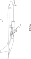
- an aircraft 10 is illustrated.
- the aircraft 10 includes landing gear, which may include a left main landing gear 12, a right main landing gear 14 and a nose landing gear 16.
- the landing gear support the aircraft 10 when it is not flying, allowing the aircraft 10 to taxi, take off and land without damage. While the disclosure refers to the three landing gear configurations just referred, the disclosure nevertheless contemplates any number of landing gear configurations.
- Aircraft brake arrangement 100 may include a plurality of actuator motors 102, a plurality of electromechanical brake actuators 104, a plurality of ball screws 106, an end plate 111 and a pressure plate 110, and a plurality of rotating discs 112 and stators 114 positioned in an alternating fashion between end plate 111 and pressure plate 110.
- Rotating discs 112 may rotate about an axis 115 and the stators 114 may have no angular movement relative to axis 115.
- Wheels may be coupled to rotating discs 112 such that a linear speed of the aircraft is proportional to the angular speed of rotating discs 112.
- rotating discs 112 and stators 114 are forced together in an axial direction. This causes the rotational speed of rotating discs 112 to become reduced (i.e., causes braking effect) due to friction between rotating discs 112, stators 114, end plate 111 and pressure plate 110. In response to sufficient force being exerted on rotating discs 112 via pressure plate 110, the rotating discs 112 will stop rotating.
- actuator motor 102 may cause electromechanical brake actuator 104 to actuate.
- electromechanical brake actuator 104 may be an electrohydraulic actuator.
- actuator motor 102 may be a brushless motor, such as a permanent magnet synchronous motor (PMSM), a permanent-magnet motor (PMM) or the like.
- electromechanical brake actuator 104 may be coupled to or otherwise operate a motor shaft and a pressure generating device, such as, for example, a ball screw, a ram, and/or the like. In response to actuation or a brake command, electromechanical brake actuator 104 causes the motor shaft to rotate.
- a pressure generating device such as, for example, a ball screw, a ram, and/or the like.
- Rotation of the motor shaft 204 may cause rotation of a ball screw 206 (e.g., see FIG. 2 ), and rotational motion of the ball screw 206 may be transformed into linear motion of a ball nut 106.
- Linear translation of ball nut 106 towards pressure plate 110 applies force on pressure plate 110 towards end plate 111.
- Electromechanical brake actuator 104 is actuated in response to current being applied to actuator motor 102.
- the amount of force applied by electromechanical brake actuator 104 is related to the amount of current applied to actuator motor 102.
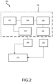
- an electromechanical brake actuator control system 200 may comprise a current sensor 212 to detect an amount of current provided to actuator motor 102.
- Current sensor 212 may be in communication with actuator motor 102 and/or with various other components of an electromechanical brake actuator 104, an electromechanical brake actuator control system 200, and/or an aircraft 10.
- current sensor 212 may be disposed on or adjacent to actuator motor 102. However, current sensor 212 may be disposed in any location suitable for detection of electrical current supplied to the actuator motor 102.
- electromechanical brake actuator control system 200 may comprise a position sensor 208.
- Position sensor 208 may be configured so as to measure the rotational speed and position of motor shaft 204.
- position sensor 208 may be disposed in or adjacent to electromechanical brake actuator 104, or on or adjacent to actuator motor 102.
- position sensor 208 may be disposed in any location suitable for detection of the rotational speed and position of motor shaft 204.
- position sensor 208 may comprise a resolver, tachometer, or the like.
- electromechanical brake actuator control system 200 may comprise a load cell 202.
- Load cell 202 may be configured so as to measure the amount of force being applied between ball nut 106 and pressure plate 110.
- load cell 202 may be disposed in or adjacent to electromechanical brake actuator 104, or on or adjacent to ball nut 106.
- load cell 202 may be disposed in any location suitable for detection of the force being applied between ball nut 106 and pressure plate 110.
- a controller may receive the detected force and rotational speed, and calculate an adjusted force and an adjusted rotational speed based on those detected values.
- electromechanical brake actuator control system 200 may comprise a fault tolerant module 210.
- a system for brake actuator operation with load cell fault tolerant technology comprises four load cells 202 and four position sensors 208 and at least one controller.
- the system for multiple brake actuator operation via one load cell may comprise a fault tolerant module 210.
- fault tolerant module 210 may be a controller and/or processor.
- fault tolerant module 210 may be implemented in a single controller and/or processor.
- fault tolerant module 210 may be implemented in multiple controllers and/or processors.
- fault tolerant module 210 may be implemented in an electromechanical actuator controller and/or a brake control unit.
- the brake actuator plate assembly 300 is illustrated.
- the brake actuator plate assembly 300 is configured to reduce reliance on external wiring harnesses for electromechanical brakes.
- the brake actuator plate assembly 300 comprises the electromechanical brake actuator 104, a wire harness 302, a connector 304, and an actuator plate 306.
- the electromechanical brake actuator 104, or EBA may be a bolt-on EBA.
- the wire harness 302 may be an electrical harness that conducts power (e.g., high voltages and/or currents) and signals (low voltages and/or currents) to and from the EBAs 104 of the aircraft brake arrangement 100, the EBAs 104 are configured to send power to drive the actuator motor 102 and receive feedback signals (e.g., how much clamp force is being applied, whether the parking brake is set, etc.).
- the wire harness may include a plurality of wires with a variety of thicknesses and insulation configured to transmit the desired data or power, etc.
- the wire harness 302 may comprise a plurality of wires for each function.
- the wire harness 302 within the brake actuator plate assembly 300 may terminate at the connector 304.
- the connector 304 is configured to communicatively couple with the aircraft brake arrangement 100.
- the actuator plate 304 may comprise a wire harness channel 308.
- the wire harness channel 308 may be configured to house the wire harness 302 within the actuator plate 304.
- Wire harness 302 as disclosed herein is integrated into the actuator plate 304.
- the wire harness channel 308 may be disposed within (e.g., embedded or contained within) or at least partially within internal cavities within the actuator plate 304.
- the wire harness channel 308 may be configured to run circumferentially around the actuator plate 306.
- the wire harness channel 308 may be configured substantially concentric with the circumference of the actuator plate 308.
- the wire harness channel 308 may be configured to be straight in between each EBA 104 and the connector 304 (e.g., forming a diamond or a star shaped pathway).
- the wire harness channel 308 may be configured to run along on side of the actuator place 306.
- the wire harness channel 308 may include two wire harness channels 308. Accordingly, the two wire harness channels 308 may run concentrically to one another.
- the brake actuator plate assembly 300 may include at least one channel arm 310.
- the at least one channel arm 310 may extend from the wire harness channel 308.
- the wire harness channel 308 may be configured as an annulus and the channel arm 310 may extend from the wire harness channel 308 to the connector 304.
- the wire harness 302 may be configured to be routed through the wire harness channel 308.
- the wire harness channel 308 is configured to form any suitable pathway between the main connector 304 and each of the EBA 104 positions and/or to a sensor (e.g., a temperature sensor).
- the wire harness channel 308 must be large enough to house all of the wires, and be configured to provide a path between the main connector 304 and the appropriate designation (e.g. one or more of the EBAs, or temperature sensor, etc.).
- Each wire within the wire harness 302 may be disposed within the wire harness channel 308, running from the main connector 304, around the actuator plate 308, and ending at at least one of the EBAs 104 (e.g., four EBAs 104 as show).
- the wire harness 104 may be configured to transfer commons signals (e.g., a sensor excitation voltage, power if the motor controller is located in the EBA itself, etc.).
- Common wires may be configured to branch off within the wire harness 302 to each of the EBAs 104 via normal wiring harness construction methods.
- the wire harness channel 308 may be machined, forged, or formed via additive manufacturing into the actuator plate 306. In such configurations wherein the wire harness channel 308 is created/embedded within the actuator plate 306, the wire harness 104 is then fed, or threaded through the wire harness channel 308.
- the wire harness 302 may be a separate line replaceable unit (LRU). As such, the correct wires per a predetermined function (e.g., a wiring diagram or schematic provided to a supplier) for the wire harness 302 are selected and pulled through actuator plate harness openings to position the wire harness 302 within the actuator plate 306, or the wire harness 302 is laid in the wire harness channel 308.
- LRU line replaceable unit
- methods of positioned the wire harness 302 within the brake actuator plate assembly 300 may include 1) positioning each wire of the wire harness 302 one at a time within the brake actuator plate assembly 300, 2) creating the harness layout on a build plate and transferring to the brake actuator plate assembly 300, or 3) a combination of either method. All of the wires terminate at the appropriate locations (e.g. main connector, EBA(s), temperature sensor) and pins or pads for the type of interface the design calls for are added. The brake actuator plate assembly 300 may then be sealed. Lastly, the EBA 104 may be added to the brake actuator plate assembly 300 to fully assemble the overall the EBA 104.
- the actuator plate 306 may be composed of a two-part assembly, such that the wire harness channel 308 is formed into at least one part of the two-part assembly and the wire harness 302 may be disposed in between the two-parts of the actuator plate 306.
- the wire harness channel 308 may be formed within a base portion of the actuator plate 306, the wire harness 302 is then positioned within the wire harness channel 308 of the base portion, and a top portion of the actuator plate 305 is placed on top.
- one or more gaskets may be included to seal the actuator plate 308.
- the top portion of the actuator plate 305 may include a flat surface such that the wire harness channel 308 of the base portion is sized and shaped to receive the entirety of the wire harness 302.
- the top portion of the actuator plate 305 may include a wire harness channel 308 such that the wire harness channel 308 of the base portion and the wire harness channel 308 of the top portion together house the entirety of the wire harness 302.
- the wire harness channel 308 is not necessarily embedded in the actuator plate 306, but instead, the wire harness channel 308 is configured as a shallow groove, or recessed channel, on a surface of the actuator plate 306. Accordingly, the brake actuator plate assembly may include a cover plate to cover and protect the wire harness 302 when positioned in the wire harness channel 308, essentially sealing the wire harness 104 within the actuator plate assembly 300.
- the brake actuator plate assembly 300 comprises contacts 312 (e.g., pins, pads, sockets, etc.).
- the contacts 312 may be an electrical interface or connection point configured to connect the electric actuator to the aircraft's electrical system, thus allowing the electric actuator to send and receive power and/or signals to and from the aircraft.
- the contacts 312 may be configured to interface with and detect signals from a secondary component 316 (e.g., a temperature sensor, a charging pad, etc.). Accordingly, the brake actuator plate assembly 300 creates a nearly connectorless electromechanical brake actuator interface for power and control.
- the secondary component 316 may be any component (e.g., a mating pad) suitable to couple with the contacts 312 via electronic communication, inductive electrical communication.
- the secondary component 316 may be configured to transfer power without physically interfacing/contact with the contacts 312.
- electronic communication means communication of electronic signals with physical coupling (e.g., “electrical communication” or “electrically coupled”) or without physical coupling and via an electromagnetic field (e.g., “inductive communication” or “inductively coupled” or “inductive coupling”).
- the secondary component 316 may be integrated with the actuator plate 306 and a gasket to seal around the perimeter between the actuator plate 306 and the secondary component 316.
- the brake actuator plate assembly 300 may be configured to make electrical contact with the secondary component 316 by bolting the brake actuator plate assembly 300 in place, as opposed to screwing on or otherwise attaching a contact to an external harness connection.
- the EBA 104 may include smart electronics onboard.
- the smart electronics are configured to digitally communicate to the AC status of all of its internal sensors (e.g., temperature, load cell, park brake status, etc.) over a single pair of wires.
- the secondary component 316 may include load cell sensors, parking brakes, or any analog or digital signal.
- the smart electronics of the EBA may be configured to communicate with the aircraft regarding status, performance, health monitoring, etc.
- the brake actuator plate assembly 300 comprises sensor contacts 314.
- the sensor contacts 314 may be configured to interface with and pick up signals regarding braking events.
- the sensor contacts 314 may be configured to contact a brake temperature sensor such that the sensor contacts 314 may be configured to interface with and pick up signals regarding the heat during braking events.
- the brake temperature sensor is configured to monitor the temperature of the brake stack.
- the brake temperature sensor may be included in the wire harness 302 routed within the actuator plate 306.
- the electromechanical brake actuator control system 200 may comprise a temperature sensor 210 (e.g., see FIG. 2 ) to detect the temperature of actuator motor 102. Temperature sensor 210 may be in communication with actuator motor 102 and/or with various other components of an electromechanical brake actuator 104, an electromechanical brake actuator control system 200, and/or an aircraft 10. In various embodiments, temperature sensor 210 may be disposed on or adjacent to actuator motor 102. However, temperature sensor 210 may be disposed in any location suitable for detection of the temperature of actuator motor 102.
- the brake actuator plate assembly 300 may include various sensor contacts configured to send signals regarding various operation events.
- a brake actuator plate assembly beneficially eliminates external wiring harness for an electromechanical brake. All wires in wire harness 302 may be hermetically sealed inside the integrated actuator plate. In various embodiments, the robustness of the seal may vary. For instance, the brake actuator plate assembly may be unsealed. In various embodiments, the brake actuator plate assembly may include drainage holes to mitigate moisture ingress. No external actuator connectors are needed between electromechanical brake actuators and the actuator plate, and the associated pads or pins may be protected from environment within a sealed integrated actuator plate. Thus, the brake actuator plate assembly improves reliability and lifespan of the system.
- brake actuator plate assembly as described herein may reduce or eliminate the need for connector strain relief, and reduce or eliminate dynamic "shaking" of an external harness during impact (e.g., during landing events).
- references to "various embodiments”, “one embodiment”, “an embodiment”, “an example embodiment”, etc. indicate that the embodiment described may include a particular feature, structure, or characteristic, but every embodiment may not necessarily include the particular feature, structure, or characteristic. Moreover, such phrases are not necessarily referring to the same embodiment. Further, when a particular feature, structure, or characteristic is described in connection with an embodiment, it is submitted that it is within the knowledge of one skilled in the art to affect such feature, structure, or characteristic in connection with other embodiments whether or not explicitly described. After reading the description, it will be apparent to one skilled in the relevant art(s) how to implement the disclosure in alternative embodiments within the scope of the claims.
Landscapes
- Engineering & Computer Science (AREA)
- General Engineering & Computer Science (AREA)
- Mechanical Engineering (AREA)
- Transportation (AREA)
- Aviation & Aerospace Engineering (AREA)
- Braking Systems And Boosters (AREA)
Abstract
Description
- The present disclosure relates to aircraft braking systems, and more specifically, to the packaging of electrical wires and interface with actuators.
- Typically, an aircraft may comprise a plurality of electromechanical brake assemblies that are configured to apply force to a brake stack on an aircraft wheel. Currently, an electrical harness is included in electromechanical brake assemblies, but these may be exposed to harsh environments. For instance, standard connectors may be moisture ingress failure points, the electrical harness may be exposed to environmental hazards such as being contacted by operators and/or with other machinery, which can damage the electrical harness. Such failures can impact brake reliability.
- Systems are provided herein for a brake actuator plate assembly. The brake actuator plate assembly includes an electromechanical brake actuator, a connector configured to communicatively couple with an aircraft, a wire harness configured to terminate at the connector and conduct at least one of a voltage or a current to and from an actuator motor, and an actuator plate comprising a wire harness channel configured to house the wire harness.
- In various embodiments, the wire harness is disposed in the actuator plate.
- In various embodiments, the wire harness channel is an internal cavity within the actuator plate.
- In various embodiments, the wire harness channel is configured circumferentially around the actuator plate.
- In various embodiments, the brake actuator plate assembly further includes a second wire harness channel.
- In various embodiments, the brake actuator plate assembly further includes at least one channel arm.
- In various embodiments, the at least one channel arm is configured to extend from the wire harness channel to the connector.
- In various embodiments, the wire harness channel is formed via at least one of machining, forging, or additive manufacturing.
- In various embodiments, the brake actuator plate assembly further includes contacts configured to interface with and detect signals from a secondary component.
- In various embodiments, the wire harness channel is a recessed channel within the actuator plate. The brake actuator plate assembly further comprises a cover plate.
- In various embodiments, the brake actuator plate assembly further includes a sensor contact for a brake temperature sensor. The sensor contact is configured to interface with and transmit signals regarding heat from a temperature sensor during a braking event.
- A brake actuator plate assembly is disclosed herein. The brake actuator plate assembly includes an actuator plate having a wire harness channel formed therein and an electromechanical brake actuator coupled to the actuator plate. The brake actuator plate assembly includes a connector disposed on the actuator plate and a wire harness disposed within the wire harness channel. The connector is configured to communicatively couple with an aircraft, and the wire harness electrically couples the connector and the electromechanical brake actuator.
- An aircraft brake arrangement is disclosed herein. The aircraft brake arrangement includes an actuator plate assembly, an actuator motor coupled to the electromechanical brake actuator and configured to cause the electromechanical brake actuator to actuate, a ball screw and a motor shaft coupled to the electromechanical brake actuators, an end plate, a pressure plate, and a plurality of rotating discs and stators positioned in an alternating fashion between the end plate and the pressure plate. The actuator plate assembly includes an electromechanical brake actuator and an actuator plate having a wire harness disposed in the actuator plate. In response to a brake command, the electromechanical brake actuator causes the motor shaft to rotate, thus moving the ball screw toward the pressure plate, the pressure plate applying force towards the end plate.
- In various embodiments, the electromechanical brake actuator is an electrohydraulic actuator.
- In various embodiments, the electromechanical brake actuator is actuated in response to current being applied to the actuator motor.
- In various embodiments, the actuator plate assembly further includes a connector configured to communicatively couple with an aircraft. The wire harness is configured to terminate at the connector and conduct at least one of a voltage or a current to and from the actuator motor.
- In various embodiments, the actuator plate includes a wire harness channel configured to house the wire harness.
- In various embodiments, the wire harness is disposed in the actuator plate such that the wire harness channel is an internal cavity within the actuator plate.
- In various embodiments, the actuator plate assembly further includes at least one channel arm configured to extend from the wire harness channel to the connector.
- In various embodiments, the actuator plate assembly further includes contacts configured to interface with and detect signals from a secondary component.
- The forgoing features and elements may be combined in various combinations without exclusivity, unless expressly indicated herein otherwise. These features and elements as well as the operation of the disclosed embodiments will become more apparent in light of the following description and accompanying drawings.
- The subject matter of the present disclosure is particularly pointed out and distinctly claimed in the concluding portion of the specification. A more complete understanding of the present disclosure, however, may best be obtained by referring to the detailed description and claims when considered in connection with the drawing figures, wherein like numerals denote like elements.
-
FIG. 1A illustrates an exemplary aircraft having a brake system, in accordance with various embodiments; -
FIG. 1B illustrates an aircraft brake in accordance with various embodiments; -
FIG. 2 illustrates a block diagram of an electromechanical brake actuator control system in accordance with various embodiments; and -
FIGs. 3A and3B illustrate a brake actuator plate, in accordance with various embodiments. - The detailed description of exemplary embodiments herein makes reference to the accompanying drawings, which show exemplary embodiments by way of illustration. While these exemplary embodiments are described in sufficient detail to enable those skilled in the art to practice the disclosure, it should be understood that other embodiments may be realized and that logical changes and adaptations in design and construction may be made in accordance with this disclosure and the teachings herein. Thus, the detailed description herein is presented for purposes of illustration only and not of limitation. The scope of the disclosure is defined by the appended claims. For example, the steps recited in any of the method or process descriptions may be executed in any order and are not necessarily limited to the order presented. Furthermore, any reference to singular includes plural embodiments, and any reference to more than one component or step may include a singular embodiment or step.
- As used herein, "electronic communication" means communication of electronic signals with physical coupling (e.g., "electrical communication" or "electrically coupled") or without physical coupling and via an electromagnetic field (e.g., "inductive communication" or "inductively coupled" or "inductive coupling").
- While described in the context of aircraft applications, and more specifically, in the context of brake control, the various embodiments of the present disclosure may be applied to any suitable application.
- Referring to
Figure 1A , in accordance with various embodiments, anaircraft 10 is illustrated. Theaircraft 10 includes landing gear, which may include a leftmain landing gear 12, a rightmain landing gear 14 and anose landing gear 16. The landing gear support theaircraft 10 when it is not flying, allowing theaircraft 10 to taxi, take off and land without damage. While the disclosure refers to the three landing gear configurations just referred, the disclosure nevertheless contemplates any number of landing gear configurations. - Referring to
FIG. 1B , anaircraft brake arrangement 100 in accordance with various embodiments is illustrated.Aircraft brake arrangement 100 may include a plurality ofactuator motors 102, a plurality ofelectromechanical brake actuators 104, a plurality of ball screws 106, anend plate 111 and apressure plate 110, and a plurality ofrotating discs 112 andstators 114 positioned in an alternating fashion betweenend plate 111 andpressure plate 110. Rotatingdiscs 112 may rotate about anaxis 115 and thestators 114 may have no angular movement relative toaxis 115. Wheels may be coupled torotating discs 112 such that a linear speed of the aircraft is proportional to the angular speed ofrotating discs 112. As force is applied topressure plate 110 towardsend plate 111 along theaxis 115, rotatingdiscs 112 andstators 114 are forced together in an axial direction. This causes the rotational speed ofrotating discs 112 to become reduced (i.e., causes braking effect) due to friction betweenrotating discs 112,stators 114,end plate 111 andpressure plate 110. In response to sufficient force being exerted onrotating discs 112 viapressure plate 110, the rotatingdiscs 112 will stop rotating. - In order to exert this force onto
pressure plate 110,actuator motor 102 may causeelectromechanical brake actuator 104 to actuate. Although referred to herein aselectromechanical brake actuator 104, it is contemplated that, in various embodiments,electromechanical brake actuator 104 may be an electrohydraulic actuator. In various embodiments,actuator motor 102 may be a brushless motor, such as a permanent magnet synchronous motor (PMSM), a permanent-magnet motor (PMM) or the like. In various embodiments,electromechanical brake actuator 104 may be coupled to or otherwise operate a motor shaft and a pressure generating device, such as, for example, a ball screw, a ram, and/or the like. In response to actuation or a brake command,electromechanical brake actuator 104 causes the motor shaft to rotate. Rotation of themotor shaft 204 may cause rotation of a ball screw 206 (e.g., seeFIG. 2 ), and rotational motion of theball screw 206 may be transformed into linear motion of aball nut 106. Linear translation ofball nut 106 towardspressure plate 110 applies force onpressure plate 110 towardsend plate 111. -
Electromechanical brake actuator 104 is actuated in response to current being applied toactuator motor 102. The amount of force applied byelectromechanical brake actuator 104 is related to the amount of current applied toactuator motor 102. With reference toFIG. 2 , in various embodiments, an electromechanical brakeactuator control system 200 may comprise acurrent sensor 212 to detect an amount of current provided toactuator motor 102.Current sensor 212 may be in communication withactuator motor 102 and/or with various other components of anelectromechanical brake actuator 104, an electromechanical brakeactuator control system 200, and/or anaircraft 10. In various embodiments,current sensor 212 may be disposed on or adjacent toactuator motor 102. However,current sensor 212 may be disposed in any location suitable for detection of electrical current supplied to theactuator motor 102. - Application of current to
actuator motor 102 causes rotation ofmotor shaft 204. In various embodiments, electromechanical brakeactuator control system 200 may comprise aposition sensor 208.Position sensor 208 may be configured so as to measure the rotational speed and position ofmotor shaft 204. In various embodiments,position sensor 208 may be disposed in or adjacent toelectromechanical brake actuator 104, or on or adjacent toactuator motor 102. However,position sensor 208 may be disposed in any location suitable for detection of the rotational speed and position ofmotor shaft 204. In various embodiments,position sensor 208 may comprise a resolver, tachometer, or the like. - In various embodiments, electromechanical brake
actuator control system 200 may comprise aload cell 202.Load cell 202 may be configured so as to measure the amount of force being applied betweenball nut 106 andpressure plate 110. In various embodiments,load cell 202 may be disposed in or adjacent toelectromechanical brake actuator 104, or on or adjacent toball nut 106. However,load cell 202 may be disposed in any location suitable for detection of the force being applied betweenball nut 106 andpressure plate 110. A controller may receive the detected force and rotational speed, and calculate an adjusted force and an adjusted rotational speed based on those detected values. In various embodiments, electromechanical brakeactuator control system 200 may comprise a faulttolerant module 210. - In various embodiments, a system for brake actuator operation with load cell fault tolerant technology comprises four
load cells 202 and fourposition sensors 208 and at least one controller. The system for multiple brake actuator operation via one load cell may comprise a faulttolerant module 210. In various embodiments, faulttolerant module 210 may be a controller and/or processor. In various embodiments, faulttolerant module 210 may be implemented in a single controller and/or processor. In various embodiments, faulttolerant module 210 may be implemented in multiple controllers and/or processors. In various embodiments, faulttolerant module 210 may be implemented in an electromechanical actuator controller and/or a brake control unit. - With reference to
FIGs. 3A and3B , a brakeactuator plate assembly 300 is illustrated. The brakeactuator plate assembly 300 is configured to reduce reliance on external wiring harnesses for electromechanical brakes. The brakeactuator plate assembly 300 comprises theelectromechanical brake actuator 104, awire harness 302, aconnector 304, and anactuator plate 306. Theelectromechanical brake actuator 104, or EBA, may be a bolt-on EBA. Thewire harness 302 may be an electrical harness that conducts power (e.g., high voltages and/or currents) and signals (low voltages and/or currents) to and from theEBAs 104 of theaircraft brake arrangement 100, theEBAs 104 are configured to send power to drive theactuator motor 102 and receive feedback signals (e.g., how much clamp force is being applied, whether the parking brake is set, etc.). For instance, the wire harness may include a plurality of wires with a variety of thicknesses and insulation configured to transmit the desired data or power, etc. In various embodiments, thewire harness 302 may comprise a plurality of wires for each function. Thewire harness 302 within the brakeactuator plate assembly 300 may terminate at theconnector 304. Theconnector 304 is configured to communicatively couple with theaircraft brake arrangement 100. - The
actuator plate 304 may comprise awire harness channel 308. Thewire harness channel 308 may be configured to house thewire harness 302 within theactuator plate 304.Wire harness 302 as disclosed herein is integrated into theactuator plate 304. In other words, thewire harness channel 308 may be disposed within (e.g., embedded or contained within) or at least partially within internal cavities within theactuator plate 304. - The
wire harness channel 308 may be configured to run circumferentially around theactuator plate 306. For instance, thewire harness channel 308 may be configured substantially concentric with the circumference of theactuator plate 308. In various embodiments, thewire harness channel 308 may be configured to be straight in between eachEBA 104 and the connector 304 (e.g., forming a diamond or a star shaped pathway). In various embodiments, thewire harness channel 308 may be configured to run along on side of theactuator place 306. In various embodiments, thewire harness channel 308 may include twowire harness channels 308. Accordingly, the twowire harness channels 308 may run concentrically to one another. - The brake
actuator plate assembly 300 may include at least onechannel arm 310. The at least onechannel arm 310 may extend from thewire harness channel 308. For instance, thewire harness channel 308 may be configured as an annulus and thechannel arm 310 may extend from thewire harness channel 308 to theconnector 304. Thewire harness 302 may be configured to be routed through thewire harness channel 308. In various embodiments, thewire harness channel 308 is configured to form any suitable pathway between themain connector 304 and each of theEBA 104 positions and/or to a sensor (e.g., a temperature sensor). For instance, thewire harness channel 308 must be large enough to house all of the wires, and be configured to provide a path between themain connector 304 and the appropriate designation (e.g. one or more of the EBAs, or temperature sensor, etc.). - Each wire within the
wire harness 302 may be disposed within thewire harness channel 308, running from themain connector 304, around theactuator plate 308, and ending at at least one of the EBAs 104 (e.g., fourEBAs 104 as show). For example, thewire harness 104 may be configured to transfer commons signals (e.g., a sensor excitation voltage, power if the motor controller is located in the EBA itself, etc.). Common wires may be configured to branch off within thewire harness 302 to each of theEBAs 104 via normal wiring harness construction methods. - In various embodiments, the
wire harness channel 308 may be machined, forged, or formed via additive manufacturing into theactuator plate 306. In such configurations wherein thewire harness channel 308 is created/embedded within theactuator plate 306, thewire harness 104 is then fed, or threaded through thewire harness channel 308. For instance, thewire harness 302 may be a separate line replaceable unit (LRU). As such, the correct wires per a predetermined function (e.g., a wiring diagram or schematic provided to a supplier) for thewire harness 302 are selected and pulled through actuator plate harness openings to position thewire harness 302 within theactuator plate 306, or thewire harness 302 is laid in thewire harness channel 308. For instance, methods of positioned thewire harness 302 within the brakeactuator plate assembly 300 may include 1) positioning each wire of thewire harness 302 one at a time within the brakeactuator plate assembly 300, 2) creating the harness layout on a build plate and transferring to the brakeactuator plate assembly 300, or 3) a combination of either method. All of the wires terminate at the appropriate locations (e.g. main connector, EBA(s), temperature sensor) and pins or pads for the type of interface the design calls for are added. The brakeactuator plate assembly 300 may then be sealed. Lastly, theEBA 104 may be added to the brakeactuator plate assembly 300 to fully assemble the overall theEBA 104. - In various embodiments, the
actuator plate 306 may be composed of a two-part assembly, such that thewire harness channel 308 is formed into at least one part of the two-part assembly and thewire harness 302 may be disposed in between the two-parts of theactuator plate 306. For instance, thewire harness channel 308 may be formed within a base portion of theactuator plate 306, thewire harness 302 is then positioned within thewire harness channel 308 of the base portion, and a top portion of the actuator plate 305 is placed on top. In such a configuration, one or more gaskets may be included to seal theactuator plate 308. In various embodiments, the top portion of the actuator plate 305 may include a flat surface such that thewire harness channel 308 of the base portion is sized and shaped to receive the entirety of thewire harness 302. In various embodiments, the top portion of the actuator plate 305 may include awire harness channel 308 such that thewire harness channel 308 of the base portion and thewire harness channel 308 of the top portion together house the entirety of thewire harness 302. - In various embodiments, the
wire harness channel 308 is not necessarily embedded in theactuator plate 306, but instead, thewire harness channel 308 is configured as a shallow groove, or recessed channel, on a surface of theactuator plate 306. Accordingly, the brake actuator plate assembly may include a cover plate to cover and protect thewire harness 302 when positioned in thewire harness channel 308, essentially sealing thewire harness 104 within theactuator plate assembly 300. - The brake
actuator plate assembly 300 comprises contacts 312 (e.g., pins, pads, sockets, etc.). Thecontacts 312 may be an electrical interface or connection point configured to connect the electric actuator to the aircraft's electrical system, thus allowing the electric actuator to send and receive power and/or signals to and from the aircraft. Thecontacts 312 may be configured to interface with and detect signals from a secondary component 316 (e.g., a temperature sensor, a charging pad, etc.). Accordingly, the brakeactuator plate assembly 300 creates a nearly connectorless electromechanical brake actuator interface for power and control. Thesecondary component 316 may be any component (e.g., a mating pad) suitable to couple with thecontacts 312 via electronic communication, inductive electrical communication. For instance, thesecondary component 316 may be configured to transfer power without physically interfacing/contact with thecontacts 312. As used herein, "electronic communication" means communication of electronic signals with physical coupling (e.g., "electrical communication" or "electrically coupled") or without physical coupling and via an electromagnetic field (e.g., "inductive communication" or "inductively coupled" or "inductive coupling"). - Further, the
secondary component 316 may be integrated with theactuator plate 306 and a gasket to seal around the perimeter between theactuator plate 306 and thesecondary component 316. Beneficially, the brakeactuator plate assembly 300 may be configured to make electrical contact with thesecondary component 316 by bolting the brakeactuator plate assembly 300 in place, as opposed to screwing on or otherwise attaching a contact to an external harness connection. - In various embodiments, the
EBA 104 may include smart electronics onboard. The smart electronics are configured to digitally communicate to the AC status of all of its internal sensors (e.g., temperature, load cell, park brake status, etc.) over a single pair of wires. For instance, within theEBAs 104, thesecondary component 316 may include load cell sensors, parking brakes, or any analog or digital signal. Thus the smart electronics of the EBA may be configured to communicate with the aircraft regarding status, performance, health monitoring, etc. - The brake
actuator plate assembly 300 comprisessensor contacts 314. Thesensor contacts 314 may be configured to interface with and pick up signals regarding braking events. For instance, thesensor contacts 314 may be configured to contact a brake temperature sensor such that thesensor contacts 314 may be configured to interface with and pick up signals regarding the heat during braking events. The brake temperature sensor is configured to monitor the temperature of the brake stack. The brake temperature sensor may be included in thewire harness 302 routed within theactuator plate 306. - Further, the electromechanical brake
actuator control system 200 may comprise a temperature sensor 210 (e.g., seeFIG. 2 ) to detect the temperature ofactuator motor 102.Temperature sensor 210 may be in communication withactuator motor 102 and/or with various other components of anelectromechanical brake actuator 104, an electromechanical brakeactuator control system 200, and/or anaircraft 10. In various embodiments,temperature sensor 210 may be disposed on or adjacent toactuator motor 102. However,temperature sensor 210 may be disposed in any location suitable for detection of the temperature ofactuator motor 102. The brakeactuator plate assembly 300 may include various sensor contacts configured to send signals regarding various operation events. - Accordingly, a brake actuator plate assembly, as described herein, beneficially eliminates external wiring harness for an electromechanical brake. All wires in
wire harness 302 may be hermetically sealed inside the integrated actuator plate. In various embodiments, the robustness of the seal may vary. For instance, the brake actuator plate assembly may be unsealed. In various embodiments, the brake actuator plate assembly may include drainage holes to mitigate moisture ingress. No external actuator connectors are needed between electromechanical brake actuators and the actuator plate, and the associated pads or pins may be protected from environment within a sealed integrated actuator plate. Thus, the brake actuator plate assembly improves reliability and lifespan of the system. Additional benefits include better support of the entire wire harness within the cavity and physical protection of wire harness from external strikes, damage, human interaction, brake dust and other contaminants, etc., thus also provided an easier brake assembly to clean. Further, the brake actuator plate assembly as described herein may reduce or eliminate the need for connector strain relief, and reduce or eliminate dynamic "shaking" of an external harness during impact (e.g., during landing events). The - Benefits, other advantages, and solutions to problems have been described herein with regard to specific embodiments. Furthermore, the connecting lines shown in the various figures contained herein are intended to represent exemplary functional relationships and/or physical couplings between the various elements. It should be noted that many alternative or additional functional relationships or physical connections may be present in a practical system. However, the benefits, advantages, solutions to problems, and any elements that may cause any benefit, advantage, or solution to occur or become more pronounced are not to be construed as critical, required, or essential features or elements of the disclosure. The scope of the disclosure is accordingly to be limited by nothing other than the appended claims, in which reference to an element in the singular is not intended to mean "one and only one" unless explicitly so stated, but rather "one or more." Moreover, where a phrase similar to "at least one of A, B, or C" is used in the claims, it is intended that the phrase be interpreted to mean that A alone may be present in an embodiment, B alone may be present in an embodiment, C alone may be present in an embodiment, or that any combination of the elements A, B and C may be present in a single embodiment; for example, A and B, A and C, B and C, or A and B and C.
- Systems, methods and apparatus are provided herein. In the detailed description herein, references to "various embodiments", "one embodiment", "an embodiment", "an example embodiment", etc., indicate that the embodiment described may include a particular feature, structure, or characteristic, but every embodiment may not necessarily include the particular feature, structure, or characteristic. Moreover, such phrases are not necessarily referring to the same embodiment. Further, when a particular feature, structure, or characteristic is described in connection with an embodiment, it is submitted that it is within the knowledge of one skilled in the art to affect such feature, structure, or characteristic in connection with other embodiments whether or not explicitly described. After reading the description, it will be apparent to one skilled in the relevant art(s) how to implement the disclosure in alternative embodiments within the scope of the claims.
Claims (15)
- A brake actuator plate assembly comprising:an electromechanical brake actuator (104);a connector (304) configured to communicatively couple with an aircraft;a wire harness (302) configured to terminate at the connector and conduct at least one of a voltage or a current to and from an actuator motor; andan actuator plate (306) comprising a wire harness channel (308) configured to house the wire harness.
- The brake actuator plate assembly of claim 1, wherein the wire harness is disposed in the actuator plate.
- The brake actuator plate assembly of claim 2, wherein the wire harness channel is an internal cavity within the actuator plate, and optionally wherein the wire harness channel is configured circumferentially around the actuator plate.
- The brake actuator plate assembly of any preceding claim, further comprising a second wire harness channel.
- The brake actuator plate assembly of any preceding claim, further comprising at least one channel arm (310), and optionally wherein the at least one channel arm is configured to extend from the wire harness channel to the connector.
- The brake actuator plate assembly of any preceding claim, wherein the wire harness channel is formed via at least one of machining, forging, or additive manufacturing.
- The brake actuator plate assembly of any preceding claim, further comprising contacts (312) configured to interface with and detect signals from a secondary component.
- The brake actuator plate assembly of any preceding claim, wherein the wire harness channel is a recessed channel within the actuator plate, the brake actuator plate assembly further comprising a cover plate.
- The brake actuator plate assembly of any preceding claim, further comprising a sensor contact for a brake temperature sensor wherein the sensor contact is configured to interface with and transmit signals regarding heat from a temperature sensor during a braking event.
- A brake actuator plate assembly comprising:an actuator plate (304) comprising a wire harness channel (308) formed therein;an electromechanical brake actuator (104) coupled to the actuator plate;a connector (304) disposed on the actuator plate, the connector configured to communicatively couple with an aircraft; anda wire harness (302) disposed within the wire harness channel and electrically coupling the connector and the electromechanical brake actuator.
- An aircraft brake arrangement comprising:an actuator plate (304) assembly comprising an electromechanical brake actuator and an actuator plate having a wire harness disposed in the actuator plate;an actuator motor (102) coupled to the electromechanical brake actuator and configured to cause the electromechanical brake actuator to actuate;a ball screw (206) and a motor shaft (204) coupled to the electromechanical brake actuators;an end plate (111) ;a pressure plate (110); anda plurality of rotating discs (112) and stators (114) positioned in an alternating fashion between the end plate (111) and the pressure plate (110),wherein, in response to a brake command, the electromechanical brake actuator causes the motor shaft to rotate, thus moving the ball screw toward the pressure plate, the pressure plate applying force towards the end plate.
- The aircraft brake arrangement of claim 11, wherein the electromechanical brake actuator is an electrohydraulic actuator and/or wherein the electromechanical brake actuator is actuated in response to current being applied to the actuator motor.
- The aircraft brake arrangement of claim 12, wherein the actuator plate assembly further comprises a connector (304) configured to communicatively couple with an aircraft, the wire harness configured to terminate at the connector and conduct at least one of a voltage or a current to and from the actuator motor.
- The aircraft brake arrangement of claim 13, wherein the actuator plate comprises a wire harness channel (308) configured to house the wire harness, and optionally wherein the wire harness is disposed in the actuator plate such that the wire harness channel is an internal cavity within the actuator plate.
- The aircraft brake arrangement of claim 14, wherein the actuator plate assembly further comprises at least one channel arm (310) configured to extend from the wire harness channel to the connector and/or wherein the actuator plate assembly further comprises contacts configured to interface with and detect signals from a secondary component.
Applications Claiming Priority (1)
| Application Number | Priority Date | Filing Date | Title |
|---|---|---|---|
| US18/108,505 US20240270216A1 (en) | 2023-02-10 | 2023-02-10 | Integrated actuator plate for ebrake |
Publications (1)
| Publication Number | Publication Date |
|---|---|
| EP4414226A1 true EP4414226A1 (en) | 2024-08-14 |
Family
ID=89900860
Family Applications (1)
| Application Number | Title | Priority Date | Filing Date |
|---|---|---|---|
| EP24157038.1A Pending EP4414226A1 (en) | 2023-02-10 | 2024-02-12 | Integrated actuator plate for ebrake |
Country Status (2)
| Country | Link |
|---|---|
| US (1) | US20240270216A1 (en) |
| EP (1) | EP4414226A1 (en) |
Families Citing this family (1)
| Publication number | Priority date | Publication date | Assignee | Title |
|---|---|---|---|---|
| US12269709B2 (en) * | 2021-09-23 | 2025-04-08 | Fisher-Barton Inc. | Tension brake |
Citations (4)
| Publication number | Priority date | Publication date | Assignee | Title |
|---|---|---|---|---|
| US20060152074A1 (en) * | 2005-01-11 | 2006-07-13 | Messier-Bugatti | Method of managing the parking force generated by a vehicle brake system equipped with electric brakes |
| US20070187192A1 (en) * | 2003-04-30 | 2007-08-16 | Steve Anderson | Electric brake for aircraft |
| US20130341134A1 (en) * | 2012-06-25 | 2013-12-26 | Messier-Bugatti-Dowty | Method of unblocking an aircraft wheel brake |
| US9428162B1 (en) * | 2015-05-19 | 2016-08-30 | Goodrich Corporation | System and method for brake control in response to load cell failure |
Family Cites Families (9)
| Publication number | Priority date | Publication date | Assignee | Title |
|---|---|---|---|---|
| FR1436050A (en) * | 1965-03-11 | 1966-04-22 | Hispano Suiza Lallemant Soc | Improvements in aviation wheel brakes |
| US3887046A (en) * | 1974-05-17 | 1975-06-03 | Wagner Electric Corp | Quick installation vehicle wheel sensor |
| US3998298A (en) * | 1975-10-28 | 1976-12-21 | Wagner Electric Corporation | Antilock sensor assembly |
| US7527129B2 (en) * | 2004-08-31 | 2009-05-05 | Honeywell International Inc. | Brake carrier having improved electromechanical actuator and mounting arrangement therefor |
| EP2060821A1 (en) * | 2007-11-14 | 2009-05-20 | Goodrich Corporation | Aircraft brake and method with electromechanical actuator modules |
| US9958068B2 (en) * | 2014-03-21 | 2018-05-01 | Goodrich Corporation | Piston housing system and apparatus |
| FR3044296B1 (en) * | 2015-12-01 | 2017-12-29 | Messier Bugatti Dowty | ARCHITECTURE OF BRAKE SYSTEM FOR AERONOEF. |
| US9995353B2 (en) * | 2015-12-21 | 2018-06-12 | Goodrich Corporation | Modified actuator design to improve load distribution and damping |
| US11312483B2 (en) * | 2019-05-10 | 2022-04-26 | Goodrich Corporation | Landing gear with hydraulic fluid channels |
-
2023
- 2023-02-10 US US18/108,505 patent/US20240270216A1/en active Pending
-
2024
- 2024-02-12 EP EP24157038.1A patent/EP4414226A1/en active Pending
Patent Citations (4)
| Publication number | Priority date | Publication date | Assignee | Title |
|---|---|---|---|---|
| US20070187192A1 (en) * | 2003-04-30 | 2007-08-16 | Steve Anderson | Electric brake for aircraft |
| US20060152074A1 (en) * | 2005-01-11 | 2006-07-13 | Messier-Bugatti | Method of managing the parking force generated by a vehicle brake system equipped with electric brakes |
| US20130341134A1 (en) * | 2012-06-25 | 2013-12-26 | Messier-Bugatti-Dowty | Method of unblocking an aircraft wheel brake |
| US9428162B1 (en) * | 2015-05-19 | 2016-08-30 | Goodrich Corporation | System and method for brake control in response to load cell failure |
Also Published As
| Publication number | Publication date |
|---|---|
| US20240270216A1 (en) | 2024-08-15 |
Similar Documents
| Publication | Publication Date | Title |
|---|---|---|
| US6908229B2 (en) | Instrumented roller bearing, in particular for control wheel | |
| US8829740B2 (en) | Sealed linear motor system | |
| EP1845001A2 (en) | Electro mechanical brake, control device | |
| US8839918B2 (en) | Electromechanical actuator with dual excitation | |
| US9610927B2 (en) | Systems and methods for electric brake force estimation tolerant to drivetrain stiction | |
| US20080091326A1 (en) | Electro Mechanical Brake | |
| EP3098126A1 (en) | Systems and methods for brake actuator operation under load cell failure | |
| US20240270216A1 (en) | Integrated actuator plate for ebrake | |
| US20160226349A1 (en) | Electromechanical linear actuator | |
| US20130341134A1 (en) | Method of unblocking an aircraft wheel brake | |
| WO2020197089A1 (en) | Brake or steering system having redundant components | |
| US20230192040A1 (en) | Electrohydraulic brake module | |
| CN108381516A (en) | Robot | |
| CN110963025A (en) | Aircraft brake system architecture | |
| US11427170B2 (en) | Vehicle brake system | |
| EP3187385B1 (en) | System and method for brake actuator operation sensor error compensation | |
| US9566970B2 (en) | Electromechanical actuator for a brake | |
| US10807574B2 (en) | Electrical harness | |
| CN219608289U (en) | Force sensor | |
| CN219608288U (en) | Force sensor | |
| KR20190004277A (en) | Vehicle actuator device, brake system | |
| US20180219461A1 (en) | Robot | |
| CN212159834U (en) | Wheel speed sensor and vehicle | |
| US20250145129A1 (en) | Force control for an electromechanical brake actuator | |
| EP4381570A1 (en) | Integrated motor device with plug-connected motor unit and servo drive unit |
Legal Events
| Date | Code | Title | Description |
|---|---|---|---|
| PUAI | Public reference made under article 153(3) epc to a published international application that has entered the european phase |
Free format text: ORIGINAL CODE: 0009012 |
|
| STAA | Information on the status of an ep patent application or granted ep patent |
Free format text: STATUS: THE APPLICATION HAS BEEN PUBLISHED |
|
| AK | Designated contracting states |
Kind code of ref document: A1 Designated state(s): AL AT BE BG CH CY CZ DE DK EE ES FI FR GB GR HR HU IE IS IT LI LT LU LV MC ME MK MT NL NO PL PT RO RS SE SI SK SM TR |
|
| STAA | Information on the status of an ep patent application or granted ep patent |
Free format text: STATUS: REQUEST FOR EXAMINATION WAS MADE |
|
| 17P | Request for examination filed |
Effective date: 20250212 |
|
| GRAP | Despatch of communication of intention to grant a patent |
Free format text: ORIGINAL CODE: EPIDOSNIGR1 |
|
| STAA | Information on the status of an ep patent application or granted ep patent |
Free format text: STATUS: GRANT OF PATENT IS INTENDED |
|
| INTG | Intention to grant announced |
Effective date: 20251008 |
|
| RAP3 | Party data changed (applicant data changed or rights of an application transferred) |
Owner name: GOODRICH CORPORATION |
|
| GRAJ | Information related to disapproval of communication of intention to grant by the applicant or resumption of examination proceedings by the epo deleted |
Free format text: ORIGINAL CODE: EPIDOSDIGR1 |
|
| STAA | Information on the status of an ep patent application or granted ep patent |
Free format text: STATUS: REQUEST FOR EXAMINATION WAS MADE |
|
| INTC | Intention to grant announced (deleted) | ||
| STAA | Information on the status of an ep patent application or granted ep patent |
Free format text: STATUS: EXAMINATION IS IN PROGRESS |