EP4414200A2 - Vehicle display device, vehicle display method, and non-transitory storage medium - Google Patents
Vehicle display device, vehicle display method, and non-transitory storage medium Download PDFInfo
- Publication number
- EP4414200A2 EP4414200A2 EP24154910.4A EP24154910A EP4414200A2 EP 4414200 A2 EP4414200 A2 EP 4414200A2 EP 24154910 A EP24154910 A EP 24154910A EP 4414200 A2 EP4414200 A2 EP 4414200A2
- Authority
- EP
- European Patent Office
- Prior art keywords
- state
- image
- vehicle
- display
- coasting
- Prior art date
- Legal status (The legal status is an assumption and is not a legal conclusion. Google has not performed a legal analysis and makes no representation as to the accuracy of the status listed.)
- Pending
Links
- 238000000034 method Methods 0.000 title claims description 31
- 230000001133 acceleration Effects 0.000 claims abstract description 15
- 230000006870 function Effects 0.000 claims description 18
- 230000008569 process Effects 0.000 description 21
- 238000001514 detection method Methods 0.000 description 10
- 230000008859 change Effects 0.000 description 8
- 238000012806 monitoring device Methods 0.000 description 7
- 238000010586 diagram Methods 0.000 description 6
- 239000000446 fuel Substances 0.000 description 6
- 239000011521 glass Substances 0.000 description 5
- 230000004397 blinking Effects 0.000 description 4
- 239000002826 coolant Substances 0.000 description 4
- 230000007423 decrease Effects 0.000 description 4
- 230000005856 abnormality Effects 0.000 description 2
- 238000004891 communication Methods 0.000 description 1
- 230000006872 improvement Effects 0.000 description 1
- 239000004973 liquid crystal related substance Substances 0.000 description 1
- 239000007787 solid Substances 0.000 description 1
Images



Classifications
-
- B—PERFORMING OPERATIONS; TRANSPORTING
- B60—VEHICLES IN GENERAL
- B60K—ARRANGEMENT OR MOUNTING OF PROPULSION UNITS OR OF TRANSMISSIONS IN VEHICLES; ARRANGEMENT OR MOUNTING OF PLURAL DIVERSE PRIME-MOVERS IN VEHICLES; AUXILIARY DRIVES FOR VEHICLES; INSTRUMENTATION OR DASHBOARDS FOR VEHICLES; ARRANGEMENTS IN CONNECTION WITH COOLING, AIR INTAKE, GAS EXHAUST OR FUEL SUPPLY OF PROPULSION UNITS IN VEHICLES
- B60K35/00—Instruments specially adapted for vehicles; Arrangement of instruments in or on vehicles
- B60K35/20—Output arrangements, i.e. from vehicle to user, associated with vehicle functions or specially adapted therefor
- B60K35/28—Output arrangements, i.e. from vehicle to user, associated with vehicle functions or specially adapted therefor characterised by the type of the output information, e.g. video entertainment or vehicle dynamics information; characterised by the purpose of the output information, e.g. for attracting the attention of the driver
-
- B—PERFORMING OPERATIONS; TRANSPORTING
- B60—VEHICLES IN GENERAL
- B60W—CONJOINT CONTROL OF VEHICLE SUB-UNITS OF DIFFERENT TYPE OR DIFFERENT FUNCTION; CONTROL SYSTEMS SPECIALLY ADAPTED FOR HYBRID VEHICLES; ROAD VEHICLE DRIVE CONTROL SYSTEMS FOR PURPOSES NOT RELATED TO THE CONTROL OF A PARTICULAR SUB-UNIT
- B60W50/00—Details of control systems for road vehicle drive control not related to the control of a particular sub-unit, e.g. process diagnostic or vehicle driver interfaces
- B60W50/08—Interaction between the driver and the control system
- B60W50/14—Means for informing the driver, warning the driver or prompting a driver intervention
-
- B—PERFORMING OPERATIONS; TRANSPORTING
- B60—VEHICLES IN GENERAL
- B60K—ARRANGEMENT OR MOUNTING OF PROPULSION UNITS OR OF TRANSMISSIONS IN VEHICLES; ARRANGEMENT OR MOUNTING OF PLURAL DIVERSE PRIME-MOVERS IN VEHICLES; AUXILIARY DRIVES FOR VEHICLES; INSTRUMENTATION OR DASHBOARDS FOR VEHICLES; ARRANGEMENTS IN CONNECTION WITH COOLING, AIR INTAKE, GAS EXHAUST OR FUEL SUPPLY OF PROPULSION UNITS IN VEHICLES
- B60K35/00—Instruments specially adapted for vehicles; Arrangement of instruments in or on vehicles
- B60K35/20—Output arrangements, i.e. from vehicle to user, associated with vehicle functions or specially adapted therefor
- B60K35/21—Output arrangements, i.e. from vehicle to user, associated with vehicle functions or specially adapted therefor using visual output, e.g. blinking lights or matrix displays
-
- B—PERFORMING OPERATIONS; TRANSPORTING
- B60—VEHICLES IN GENERAL
- B60K—ARRANGEMENT OR MOUNTING OF PROPULSION UNITS OR OF TRANSMISSIONS IN VEHICLES; ARRANGEMENT OR MOUNTING OF PLURAL DIVERSE PRIME-MOVERS IN VEHICLES; AUXILIARY DRIVES FOR VEHICLES; INSTRUMENTATION OR DASHBOARDS FOR VEHICLES; ARRANGEMENTS IN CONNECTION WITH COOLING, AIR INTAKE, GAS EXHAUST OR FUEL SUPPLY OF PROPULSION UNITS IN VEHICLES
- B60K35/00—Instruments specially adapted for vehicles; Arrangement of instruments in or on vehicles
- B60K35/20—Output arrangements, i.e. from vehicle to user, associated with vehicle functions or specially adapted therefor
- B60K35/21—Output arrangements, i.e. from vehicle to user, associated with vehicle functions or specially adapted therefor using visual output, e.g. blinking lights or matrix displays
- B60K35/22—Display screens
-
- B—PERFORMING OPERATIONS; TRANSPORTING
- B60—VEHICLES IN GENERAL
- B60K—ARRANGEMENT OR MOUNTING OF PROPULSION UNITS OR OF TRANSMISSIONS IN VEHICLES; ARRANGEMENT OR MOUNTING OF PLURAL DIVERSE PRIME-MOVERS IN VEHICLES; AUXILIARY DRIVES FOR VEHICLES; INSTRUMENTATION OR DASHBOARDS FOR VEHICLES; ARRANGEMENTS IN CONNECTION WITH COOLING, AIR INTAKE, GAS EXHAUST OR FUEL SUPPLY OF PROPULSION UNITS IN VEHICLES
- B60K35/00—Instruments specially adapted for vehicles; Arrangement of instruments in or on vehicles
- B60K35/20—Output arrangements, i.e. from vehicle to user, associated with vehicle functions or specially adapted therefor
- B60K35/29—Instruments characterised by the way in which information is handled, e.g. showing information on plural displays or prioritising information according to driving conditions
-
- B—PERFORMING OPERATIONS; TRANSPORTING
- B60—VEHICLES IN GENERAL
- B60W—CONJOINT CONTROL OF VEHICLE SUB-UNITS OF DIFFERENT TYPE OR DIFFERENT FUNCTION; CONTROL SYSTEMS SPECIALLY ADAPTED FOR HYBRID VEHICLES; ROAD VEHICLE DRIVE CONTROL SYSTEMS FOR PURPOSES NOT RELATED TO THE CONTROL OF A PARTICULAR SUB-UNIT
- B60W30/00—Purposes of road vehicle drive control systems not related to the control of a particular sub-unit, e.g. of systems using conjoint control of vehicle sub-units
- B60W30/14—Adaptive cruise control
- B60W30/143—Speed control
-
- B—PERFORMING OPERATIONS; TRANSPORTING
- B60—VEHICLES IN GENERAL
- B60W—CONJOINT CONTROL OF VEHICLE SUB-UNITS OF DIFFERENT TYPE OR DIFFERENT FUNCTION; CONTROL SYSTEMS SPECIALLY ADAPTED FOR HYBRID VEHICLES; ROAD VEHICLE DRIVE CONTROL SYSTEMS FOR PURPOSES NOT RELATED TO THE CONTROL OF A PARTICULAR SUB-UNIT
- B60W30/00—Purposes of road vehicle drive control systems not related to the control of a particular sub-unit, e.g. of systems using conjoint control of vehicle sub-units
- B60W30/18—Propelling the vehicle
- B60W30/18009—Propelling the vehicle related to particular drive situations
- B60W30/18163—Lane change; Overtaking manoeuvres
-
- B—PERFORMING OPERATIONS; TRANSPORTING
- B60—VEHICLES IN GENERAL
- B60K—ARRANGEMENT OR MOUNTING OF PROPULSION UNITS OR OF TRANSMISSIONS IN VEHICLES; ARRANGEMENT OR MOUNTING OF PLURAL DIVERSE PRIME-MOVERS IN VEHICLES; AUXILIARY DRIVES FOR VEHICLES; INSTRUMENTATION OR DASHBOARDS FOR VEHICLES; ARRANGEMENTS IN CONNECTION WITH COOLING, AIR INTAKE, GAS EXHAUST OR FUEL SUPPLY OF PROPULSION UNITS IN VEHICLES
- B60K2360/00—Indexing scheme associated with groups B60K35/00 or B60K37/00 relating to details of instruments or dashboards
- B60K2360/16—Type of output information
- B60K2360/167—Vehicle dynamics information
-
- B—PERFORMING OPERATIONS; TRANSPORTING
- B60—VEHICLES IN GENERAL
- B60K—ARRANGEMENT OR MOUNTING OF PROPULSION UNITS OR OF TRANSMISSIONS IN VEHICLES; ARRANGEMENT OR MOUNTING OF PLURAL DIVERSE PRIME-MOVERS IN VEHICLES; AUXILIARY DRIVES FOR VEHICLES; INSTRUMENTATION OR DASHBOARDS FOR VEHICLES; ARRANGEMENTS IN CONNECTION WITH COOLING, AIR INTAKE, GAS EXHAUST OR FUEL SUPPLY OF PROPULSION UNITS IN VEHICLES
- B60K2360/00—Indexing scheme associated with groups B60K35/00 or B60K37/00 relating to details of instruments or dashboards
- B60K2360/16—Type of output information
- B60K2360/168—Target or limit values
-
- B—PERFORMING OPERATIONS; TRANSPORTING
- B60—VEHICLES IN GENERAL
- B60K—ARRANGEMENT OR MOUNTING OF PROPULSION UNITS OR OF TRANSMISSIONS IN VEHICLES; ARRANGEMENT OR MOUNTING OF PLURAL DIVERSE PRIME-MOVERS IN VEHICLES; AUXILIARY DRIVES FOR VEHICLES; INSTRUMENTATION OR DASHBOARDS FOR VEHICLES; ARRANGEMENTS IN CONNECTION WITH COOLING, AIR INTAKE, GAS EXHAUST OR FUEL SUPPLY OF PROPULSION UNITS IN VEHICLES
- B60K2360/00—Indexing scheme associated with groups B60K35/00 or B60K37/00 relating to details of instruments or dashboards
- B60K2360/16—Type of output information
- B60K2360/171—Vehicle or relevant part thereof displayed
-
- B—PERFORMING OPERATIONS; TRANSPORTING
- B60—VEHICLES IN GENERAL
- B60K—ARRANGEMENT OR MOUNTING OF PROPULSION UNITS OR OF TRANSMISSIONS IN VEHICLES; ARRANGEMENT OR MOUNTING OF PLURAL DIVERSE PRIME-MOVERS IN VEHICLES; AUXILIARY DRIVES FOR VEHICLES; INSTRUMENTATION OR DASHBOARDS FOR VEHICLES; ARRANGEMENTS IN CONNECTION WITH COOLING, AIR INTAKE, GAS EXHAUST OR FUEL SUPPLY OF PROPULSION UNITS IN VEHICLES
- B60K2360/00—Indexing scheme associated with groups B60K35/00 or B60K37/00 relating to details of instruments or dashboards
- B60K2360/16—Type of output information
- B60K2360/174—Economic driving
-
- B—PERFORMING OPERATIONS; TRANSPORTING
- B60—VEHICLES IN GENERAL
- B60K—ARRANGEMENT OR MOUNTING OF PROPULSION UNITS OR OF TRANSMISSIONS IN VEHICLES; ARRANGEMENT OR MOUNTING OF PLURAL DIVERSE PRIME-MOVERS IN VEHICLES; AUXILIARY DRIVES FOR VEHICLES; INSTRUMENTATION OR DASHBOARDS FOR VEHICLES; ARRANGEMENTS IN CONNECTION WITH COOLING, AIR INTAKE, GAS EXHAUST OR FUEL SUPPLY OF PROPULSION UNITS IN VEHICLES
- B60K2360/00—Indexing scheme associated with groups B60K35/00 or B60K37/00 relating to details of instruments or dashboards
- B60K2360/16—Type of output information
- B60K2360/175—Autonomous driving
-
- B—PERFORMING OPERATIONS; TRANSPORTING
- B60—VEHICLES IN GENERAL
- B60K—ARRANGEMENT OR MOUNTING OF PROPULSION UNITS OR OF TRANSMISSIONS IN VEHICLES; ARRANGEMENT OR MOUNTING OF PLURAL DIVERSE PRIME-MOVERS IN VEHICLES; AUXILIARY DRIVES FOR VEHICLES; INSTRUMENTATION OR DASHBOARDS FOR VEHICLES; ARRANGEMENTS IN CONNECTION WITH COOLING, AIR INTAKE, GAS EXHAUST OR FUEL SUPPLY OF PROPULSION UNITS IN VEHICLES
- B60K2360/00—Indexing scheme associated with groups B60K35/00 or B60K37/00 relating to details of instruments or dashboards
- B60K2360/16—Type of output information
- B60K2360/179—Distances to obstacles or vehicles
-
- B—PERFORMING OPERATIONS; TRANSPORTING
- B60—VEHICLES IN GENERAL
- B60K—ARRANGEMENT OR MOUNTING OF PROPULSION UNITS OR OF TRANSMISSIONS IN VEHICLES; ARRANGEMENT OR MOUNTING OF PLURAL DIVERSE PRIME-MOVERS IN VEHICLES; AUXILIARY DRIVES FOR VEHICLES; INSTRUMENTATION OR DASHBOARDS FOR VEHICLES; ARRANGEMENTS IN CONNECTION WITH COOLING, AIR INTAKE, GAS EXHAUST OR FUEL SUPPLY OF PROPULSION UNITS IN VEHICLES
- B60K2360/00—Indexing scheme associated with groups B60K35/00 or B60K37/00 relating to details of instruments or dashboards
- B60K2360/18—Information management
- B60K2360/186—Displaying information according to relevancy
- B60K2360/1868—Displaying information according to relevancy according to driving situations
-
- B—PERFORMING OPERATIONS; TRANSPORTING
- B60—VEHICLES IN GENERAL
- B60K—ARRANGEMENT OR MOUNTING OF PROPULSION UNITS OR OF TRANSMISSIONS IN VEHICLES; ARRANGEMENT OR MOUNTING OF PLURAL DIVERSE PRIME-MOVERS IN VEHICLES; AUXILIARY DRIVES FOR VEHICLES; INSTRUMENTATION OR DASHBOARDS FOR VEHICLES; ARRANGEMENTS IN CONNECTION WITH COOLING, AIR INTAKE, GAS EXHAUST OR FUEL SUPPLY OF PROPULSION UNITS IN VEHICLES
- B60K2360/00—Indexing scheme associated with groups B60K35/00 or B60K37/00 relating to details of instruments or dashboards
- B60K2360/18—Information management
- B60K2360/186—Displaying information according to relevancy
- B60K2360/1876—Displaying information according to relevancy according to vehicle situations
-
- B—PERFORMING OPERATIONS; TRANSPORTING
- B60—VEHICLES IN GENERAL
- B60K—ARRANGEMENT OR MOUNTING OF PROPULSION UNITS OR OF TRANSMISSIONS IN VEHICLES; ARRANGEMENT OR MOUNTING OF PLURAL DIVERSE PRIME-MOVERS IN VEHICLES; AUXILIARY DRIVES FOR VEHICLES; INSTRUMENTATION OR DASHBOARDS FOR VEHICLES; ARRANGEMENTS IN CONNECTION WITH COOLING, AIR INTAKE, GAS EXHAUST OR FUEL SUPPLY OF PROPULSION UNITS IN VEHICLES
- B60K2360/00—Indexing scheme associated with groups B60K35/00 or B60K37/00 relating to details of instruments or dashboards
- B60K2360/18—Information management
- B60K2360/191—Highlight information
-
- B—PERFORMING OPERATIONS; TRANSPORTING
- B60—VEHICLES IN GENERAL
- B60W—CONJOINT CONTROL OF VEHICLE SUB-UNITS OF DIFFERENT TYPE OR DIFFERENT FUNCTION; CONTROL SYSTEMS SPECIALLY ADAPTED FOR HYBRID VEHICLES; ROAD VEHICLE DRIVE CONTROL SYSTEMS FOR PURPOSES NOT RELATED TO THE CONTROL OF A PARTICULAR SUB-UNIT
- B60W50/00—Details of control systems for road vehicle drive control not related to the control of a particular sub-unit, e.g. process diagnostic or vehicle driver interfaces
- B60W50/08—Interaction between the driver and the control system
- B60W50/14—Means for informing the driver, warning the driver or prompting a driver intervention
- B60W2050/146—Display means
-
- B—PERFORMING OPERATIONS; TRANSPORTING
- B60—VEHICLES IN GENERAL
- B60Y—INDEXING SCHEME RELATING TO ASPECTS CROSS-CUTTING VEHICLE TECHNOLOGY
- B60Y2400/00—Special features of vehicle units
- B60Y2400/92—Driver displays
Definitions
- the present invention relates to vehicle display devices, vehicle display methods, and non-transitory storage media.
- JP 2021-109582 A proposes a lane change assist device including a driver assist electronic control unit (ECU).
- the driver assist ECU waits in a standby mode and displays a standby image (first image) on an information display when an operation duration, namely the time period during which a predetermined operation of a turn signal lever continues, becomes equal to or greater than a first duration threshold.
- an operation duration namely the time period during which a predetermined operation of a turn signal lever continues
- the driver assist ECU starts lane change assistance control, switches an image from the first image to a second image indicating that the lane change assistance control is being performed, and displays the second image on the information display.
- JP 2021-109582 A allows an occupant to recognize that the driver assistance is being performed but does not allow the occupant to recognize the state of the driver assistance being performed. This technique therefore has room for improvement.
- the present invention provides a vehicle display device, a vehicle display method, and a non-transitory storage medium that allow an occupant to recognize not only whether driver assistance is being performed but also the state of the driver assistance.
- a vehicle display device includes one or more processors.
- the one or more processors are configured to: acquire a state of driver assistance provided by pulse and glide that repeats acceleration and coasting, and cause a display to display a state image based on the acquired state of the driver assistance, the state image representing an accelerating state or a coasting state of the driver assistance and a rough indication of when each state is going to end.
- the state image representing the accelerating state or the coasting state of the driver assistance and the rough indication of when each state is going to end is displayed. This allows an occupant to know how much the vehicle will accelerate and how much the vehicle will coast by checking the state image. The occupant can therefore recognize not only whether the driver assistance is being performed but also the state of the driver assistance.
- the one or more processors may be configured to cause the display to display a vehicle image representing a vehicle and line images in front of and behind the vehicle image, and to cause the display to display the rough indication by changing a relative position of the vehicle image between the line images.
- the occupant can recognize how much the accelerating state or the coasting state will continue from the relative positional relationship of the vehicle image between the line images.
- the line image is highlighted, it becomes easier to know whether the state of the driver assistance is the accelerating state or the coasting state.
- the one or more processors may be configured to cause the display to display a gauge image as the state image, the gauge image representing the accelerating state or the coasting state.
- the occupant can recognize how much the accelerating state or the coasting state will continue from the gauge image.
- the one or more processors may be configured to cause the display to display an arrow image according to the accelerating state or the coasting state as the state image.
- the occupant can recognize from the arrow image whether the state of the driver assistance is the accelerating state or the coasting state.
- the one or more processors may be configured to cause the display to display a vehicle image representing a vehicle, and to display an animation image as the state image on the display, the animation image being an image that moves along a side of the vehicle image according to the accelerating state or the coasting state.
- the occupant can recognize from the animation image whether the state of the driver assistance is the accelerating state or the coasting state.
- a vehicle display control method includes: acquiring a state of driver assistance provided by pulse and glide that repeats acceleration and coasting; and displaying a state image based on the acquired state of the driver assistance, the state image representing an accelerating state or a coasting state of the driver assistance and a rough indication of when each state is going to end.
- the vehicle display method that allows an occupant to recognize not only whether the driver assistance is being performed but also the state of the driver assistance.
- a non-transitory storage medium is a non-transitory storage medium storing instructions that are executable by one or more processors and that cause the one or more processors to perform functions.
- the functions include: acquiring a state of driver assistance provided by pulse and glide that repeats acceleration and coasting; and displaying a state image based on the acquired state of the driver assistance, the state image representing an accelerating state or a coasting state of the driver assistance and a rough indication of when each state is going to end.
- the non-transitory storage medium that allows an occupant to recognize not only whether the driver assistance is being performed but also the state of the driver assistance.
- the vehicle display device As described above, according to the present invention, it is possible to provide the vehicle display device, the vehicle display method, and the non-transitory storage medium that allow an occupant to recognize not only whether the driver assistance is being performed but also the state of the driver assistance.
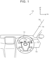
- FIG. 1 schematically shows a vehicle display device according to the present embodiment.
- the arrow UP indicates the upper side in the vehicle vertical direction
- the arrow RH indicates the right side in the vehicle lateral direction.
- the up-down direction and the left-right direction in the following description mean the upper and lower sides in the vehicle vertical direction and the left and right sides in the vehicle lateral direction.
- an instrument panel 70 is installed in the front part of a vehicle cabin of a vehicle 10.
- a windshield glass 74 is installed at the front end of the instrument panel 70.
- the windshield glass 74 extends in the vehicle vertical direction and the vehicle lateral direction and separates the inside and outside of the vehicle cabin.
- the right end in the vehicle lateral direction of the windshield glass 74 is fixed to a right front pillar 76 of the vehicle 10.
- the front pillar 76 extends in the vehicle vertical direction, and the windshield glass 74 is fixed to the inner end in the vehicle lateral direction of the front pillar 76.
- the left end in the vehicle lateral direction of the windshield glass 74 is fixed to a left front pillar, not shown, of the vehicle 10.
- the instrument panel 70 extends in the vehicle lateral direction, and a steering wheel 72 is installed on the right side in the vehicle lateral direction of the instrument panel 70. That is, according to the present embodiment, as an example, the vehicle is a righthand drive vehicle with the steering wheel 72 on the right side, and a driver's seat is on the right side of the vehicle 10.
- a display 14 of the vehicle display device is installed on the instrument panel 70 at a position in front of the steering wheel 72.
- the display 14 is a liquid crystal panel, and is configured to display the traveling state of the vehicle 10, the operating state of a driver assist device etc.
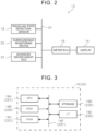
- FIG. 2 is a block diagram showing the configuration of the control system of the vehicle display device 12 according to the present embodiment.
- the vehicle display device 12 includes a meter electronic control unit (ECU) 16, a traveling state detection sensor 18, a surroundings monitoring device 20, and an advanced driver assist ECU 22. These components are connected to a vehicle network 24.
- ECU meter electronic control unit
- the vehicle display device 12 includes a meter electronic control unit (ECU) 16, a traveling state detection sensor 18, a surroundings monitoring device 20, and an advanced driver assist ECU 22. These components are connected to a vehicle network 24.
- the display 14 is connected to the meter ECU 16.
- the meter ECU 16 controls the display 14 to perform a process of displaying a plurality of meters, a process of displaying various types of vehicle information, etc.
- the meter ECU 16 notifies an occupant by displaying the occurrence of the abnormality on the display 14.
- Examples of the various types of vehicle information to be displayed on the display 14 include the operating state of the driver assist device etc.
- the display mode of the display 14 can be switched using a switch, not shown, etc., and can be changed to a display mode that matches the driver's preference.
- the traveling state detection sensor 18 detects the traveling state of the vehicle 10.
- the traveling state detection sensor 18 includes, for example, at least one of various sensors such as a vehicle speed sensor, an acceleration sensor, a gyro sensor, an accelerator operation amount sensor, and a brake sensor.
- the surroundings monitoring device 20 detects information indicating the surroundings of the vehicle 10.
- the surroundings monitoring device 20 includes at least one of various devices such as a Global Positioning System (GPS) device, an invehicle communication device, a navigation system, a radar device, and a camera.
- GPS Global Positioning System
- the advanced driver assist ECU 22 has functions to acquire surroundings information detected by the surroundings monitoring device 20 that monitors the surroundings, provide the surroundings information to other ECUs, and control steering and brakes as necessary. For example, the advanced driver assist ECU 22 performs a process of controlling the brakes to assist in deceleration when accelerator-off is detected by the traveling state detection sensor 18 and another vehicle, an intersection, etc. is detected ahead of the vehicle by the surroundings monitoring device 20.
- the advanced driver assist ECU 22 control functions such as a cruise control function to control acceleration and deceleration so that the vehicle follows the preceding vehicle while responding to changes in vehicle speed of the preceding vehicle and a lane tracing assist function to warn of the possibility of deviation from the lane or course and assist in part of the steering wheel operation to avoid deviation from the lane or course.
- cruise control functions there are two types of cruise control functions: normal cruise control that maintains a set speed, and eco-drive cruise control that performs pulse and glide for a preset speed to reduce fuel consumption.
- the pulse and glide is a driving method in which acceleration and coasting are repeated in order to reduce fuel consumption during traveling.
- the eco-drive cruise control the pulse and glide is performed so that the speed is within a predetermined allowable range up to a preset speed as an upper limit.
- FIG. 3 is a block diagram showing the configuration of a main part of an electrical system of the meter ECU 16 and the advanced driver assist ECU 22 in the vehicle display device 12 according to the present embodiment. Since the meter ECU 16 and the advanced driver assist ECU 22 basically have the configuration of a common computer, the meter ECU 16 will be representatively described.
- the meter ECU 16 is a common microcomputer including a central processing unit (CPU) 16A, a read-only memory (ROM) 16B, a random access memory (RAM) 16C, a storage 16D, an interface (I/F) 16E, and a bus 16F.
- CPU central processing unit
- ROM read-only memory
- RAM random access memory
- storage 16D a storage 16D
- I/F interface
- bus 16F bus
- the CPU 16A is a central processing unit and controls the overall operation of the device by executing various programs.
- the number of CPUs is not limited to one.
- the ROM 16B stores in advance various control programs such as a vehicle display program, various parameters, etc.
- the RAM 16C is used as a work area etc. when the CPU 16A executes the various programs.
- the storage 16D is composed of various storage units such as a hard disk drive (HDD), a solid state drive (SSD), and a flash memory, and stores various types of data, application programs, etc.
- the I/F 16E can be connected to the vehicle network 24, and sends and receives various types of data to and from other ECUs connected to the vehicle network 24 such as the meter ECU 16.
- the above components of the meter ECU 16 are electrically connected to each other via the bus 16F.
- the vehicle display program is described as being stored in the ROM 16B. However, the vehicle display program may be stored in the storage 16D.
- FIG. 4 is a functional block diagram showing the functional configurations of the meter ECU 16.
- the meter ECU 16 has the functions of an acquisition unit 26 and a control unit 28 as the CPU 16A executes the programs stored in the ROM 16B.
- the acquisition unit 26 is configured to acquire the state of driver assistance of the pulse and glide from the advanced driver assist ECU 22 when instructed to perform the eco-driving cruise control.
- the control unit 28 Based on the acquisition result of the acquisition unit 26, the control unit 28 displays a state image representing an accelerating state or coasting state of the driver assistance and a rough indication of when each state is going to end. That is, the control unit 28 displays, on the display 14, a state image representing an accelerating state or coasting state of the driver assistance and a rough indication of when each state is going to end, based on the state of the driver assistance of the pulse and glide acquired by the acquisition unit 26.
- the meter ECU 16 performs control to display the detection results from the traveling state detection sensor 18, the detection results from the surroundings monitoring device 20, etc. on the display 14.
- the meter ECU 16 also performs control to display the state of assistance from the advanced driver assist ECU 22.
- an image showing the air temperature, vehicle speed, coolant temperature, remaining fuel level, etc. is displayed on the display 14 as an example of the detection results from the traveling state detection sensor 18, and information representing other vehicles around the vehicle 10 etc. is displayed on the display 14 as the detection results from the surroundings monitoring device 20.
- An image representing the driver assistance function in operation etc. is also displayed.
- the air temperature (“75°F” in FIG. 5A ) and the vehicle speed (“100 MPH" in FIG. 5A ) are displayed numerically.
- the coolant temperature and the remaining fuel level are displayed by a coolant temperature gauge image 30 representing the coolant temperature and a fuel gauge image 32 representing the remaining fuel level, respectively.
- vehicle images 36 indicating the presence of vehicles in front and to the side of the vehicle 10 are displayed together with a vehicle image 34 representing the vehicle 10.
- the state of the driver assistance of the pulse and glide may not be known when the advanced driver assist ECU 22 is executing the eco-drive cruise control function.
- the advanced driver assist ECU 22 performs control to display a state image representing an accelerating state or coasting state caused by the advanced driver assist ECU 22 during execution of the eco-drive cruise control function and a rough indication of when each state is going to end.
- the vehicle image 34 and line images 42 in front of and behind the vehicle image 34 are displayed as the state image during the pulse and glide of the eco-drive cruise control.
- the line image 42 behind the vehicle image 34 is highlighted (e.g., displayed by a thick line or in gradation), and the relative position of the vehicle image 34 and the line images 42 is changed to display a rough indication of when the coasting state is going to end.
- the line images 42 and the vehicle image 34 are displayed in such a manner that the distance between the line image 42 behind the vehicle image 34 and the vehicle image 34 decreases as the vehicle speed gets closer to a predetermined allowable speed as a result of the coasting.
- the line image 42 in front of the vehicle image 34 is highlighted (e.g., displayed by a thick line or in gradation), and the relative position of the vehicle image 34 and the line images 42 is changed to display a rough indication of when the accelerating state is going to end.
- the line images 42 and the vehicle image 34 are displayed in such a manner that the distance between the line image 42 in front of the vehicle image 34 and the vehicle image 34 decreases as the vehicle speed gets closer to a predetermined set speed as a result of the acceleration.
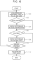
- FIG. 6 is a flowchart showing an example of the flow of a process that is performed by the meter ECU 16 of the vehicle display device 12 according to the present embodiment.
- the process of FIG. 6 is started when the advanced driver assist ECU 22 is instructed to start the eco-drive cruise control function.
- step 100 the CPU 16A acquires the driver assistance state of the pulse and glide, and the process proceeds to step 102.
- the acquisition unit 26 acquires the state of the driver assistance of the pulse and glide of the eco-drive cruise control from the advanced driver assist ECU 22.
- step 102 the CPU 16A determines whether the vehicle 10 is accelerating. This determination determines whether the state of the driver assistance of the pulse and glide is the accelerating state. When Yes in step 102, the process proceeds to step 104. When No in step 102, the process proceeds to step 106.
- step 104 the CPU 16A displays a state image when in the accelerating state on the display 14, and the process proceeds to step 106.
- the vehicle image 34 and the line images 42 in front of and behind the vehicle image 34 are displayed as the state image.
- the line image 42 in front of the vehicle image 34 is highlighted (e.g., displayed by a thick line or in gradation), and the relative position of the vehicle image 34 between the line images 42 is changed to display a rough indication of when the accelerating state is going to end.
- the line images 42 and the vehicle image 34 are displayed in such a manner that the distance between the line image 42 in front of the vehicle image 34 and the vehicle image 34 decreases as the vehicle speed gets closer to a predetermined set speed as a result of the acceleration.
- step 106 the CPU 16A determines whether the vehicle 10 is coasting. This determination determines whether the state of the driver assistance of the pulse and glide is the coasting state. When Yes in step 106, the process proceeds to step 108. When No in step 106, the process proceeds to step 110.
- step 108 the CPU 16A displays a state image when in the coasting state on the display 14, and the process proceeds to step 110.
- the vehicle image 34 and the line images 42 in front of and behind the vehicle image 34 are displayed as the state image.
- the line image 42 behind the vehicle image 34 is highlighted (e.g., displayed by a thick line or in gradation), and the relative position of the vehicle image 34 between the line images 42 is changed to display a rough indication of when the coasting state is going to end.
- the line images 42 and the vehicle image 34 are displayed in such a manner that the distance between the line image 42 behind the vehicle image 34 and the vehicle image 34 decreases as the vehicle speed gets closer to a predetermined allowable speed as a result of the coasting.
- step 110 the CPU 16A determines whether the driver assistance ends. For example, this determination determines whether an instruction to end the eco-drive cruise control function has been given. When No in step 110, the process returns to step 100 to repeat the above steps. When Yes in step 110, the process proceeds to step 112.
- step 112 the CPU 16A hides the icon 38 and the state image and ends the series of steps.
- the vehicle display device 12 displays a state image representing the accelerating state or coasting state caused by the advanced driver assist ECU 22 during execution of the eco-drive cruise control function and a rough indication of when each state is going to end. This allows the occupant to know how much the vehicle will accelerate and how much the vehicle will coast. The occupant can therefore recognize not only whether the driver assistance is being performed but also the state of the driver assistance.
- the line images 42 are displayed as a state image, the line image 42 behind the vehicle image 34 is highlighted when in the coasting state, and the line image 42 in front of the vehicle image 34 is highlighted when in the accelerating state.
- the present invention is not limited to this.
- the line images 42 may not be highlighted, and the accelerating state and the coasting state may be indicated and a rough indication of when each state is going to end may be displayed only by the change in relative position of the vehicle image 34 between the line images 42.
- a gauge image 44 representing the accelerating state or the coasting state may be displayed as a state image.
- FIGS. 7A and 7B show an example of displaying a gauge image as another example of the state image.
- the right side of the gauge image 44 in FIGS. 7A and 7B indicates the end of coasting.
- the gauge image 44 is displayed in such a manner that a gauge moves to the right as the vehicle speed gets closer to a predetermined allowable speed as a result of the coasting. From the gauge image 44, the occupant can recognize the coasting state and can also roughly recognize when the coasting state is going to end.
- the left side of the gauge image 44 indicates the end of acceleration.
- the gauge image 44 is displayed in such a manner that the gauge moves to the left as the vehicle speed gets closer to a predetermined set speed as a result of the acceleration. It is therefore possible to recognize whether the state of the driver assistance is the accelerating state or the coasting state and to roughly recognize when each state is going to end.
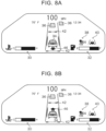
- the vehicle image 34, the line images 42, and an arrow image 46 may be displayed as a state image.
- FIG. 8A shows an example of displaying the vehicle image, the line images, and the arrow image when in the coasting state.
- FIG. 8B shows an example of displaying the vehicle image, the line images, and the arrow image when in the accelerating state.
- the vehicle image 34 is displayed between the line images 42, and the arrow image 46 is displayed in front of or behind the vehicle image 34.
- the arrow image 46 is displayed behind the vehicle image 34 as shown in FIG. 8A , it means coasting.
- the arrow image 46 is displayed in front of the vehicle image 34 as shown in FIG. 8B , it means acceleration.
- the relative position of the vehicle image 34 between the line images 42 is changed.
- the relative position of the arrow image 46 between the line images 42 is changed according to the state. It is therefore possible to recognize whether the state of the driver assistance is the accelerating state or the coasting state and to roughly recognize when each state is going to end.
- a rough indication of when each state is going to end may be displayed by other methods.
- a rough indication of when each state is going to end may be displayed by changing the display mode of the arrow image.
- the display mode of the arrow image 46 such as a color or a blinking period may be changed in several ways, and a rough indication of when each state is going to end may be displayed by the change in display mode such as the color or the blinking period.
- the vehicle image 34, the line images 42, and animation images 48 located lateral to the vehicle image 34 may be displayed as a state image.
- FIG. 9A shows an example of displaying the vehicle image, the line images, and the animation images when in the coasting state.
- FIG. 9B shows an example of displaying the vehicle image, the line images, and the animation images when in the accelerating state.
- FIGS. 9A and 9B show an example in which the animation images 48 are displayed on both sides of the vehicle image 34.
- the animation image 48 may be displayed on one side of the vehicle image 34.
- the animation images 48 are displayed so as to move in the direction forward of the vehicle image 34.
- the animation images 48 are displayed so as to move in the direction rearward of the vehicle image 34.
- a rough indication of when each state is going to end is displayed by changing the relative position of the vehicle image 34 between the line images 42. It is therefore possible to recognize whether the state of the driver assistance is the accelerating state or the coasting state and to roughly recognize when each state is going to end.
- a rough indication of when each state is going to end may be displayed by other methods.
- a rough indication of when each state is going to end may be displayed by changing the display mode of the animation images.
- the display mode of the animation images 48 such as a color or a blinking period may be changed in several ways, and a rough indication of when each state is going to end may be displayed by the change in display mode such as the color or the blinking period.
- the present invention is not limited to this.
- at least two of the state image in the above embodiment and the state images shown in FIGS. 5A, 5B , and 7A to 9B may be combined and displayed as appropriate.
- the process that is performed by the meter ECU 16 of the vehicle display device 12 in each of the above embodiments is described as a software process that is performed by executing the programs.
- the present invention is not limited to this.
- the process may be performed by hardware such as a graphics processing unit (GPU), an application specific integrated circuit (ASIC), and a field-programmable gate array (FPGA).
- the process may be performed by a combination of both software and hardware.
- the programs may be stored in various storage media and distributed.
Landscapes
- Engineering & Computer Science (AREA)
- Transportation (AREA)
- Mechanical Engineering (AREA)
- Automation & Control Theory (AREA)
- Chemical & Material Sciences (AREA)
- Combustion & Propulsion (AREA)
- Human Computer Interaction (AREA)
- Instrument Panels (AREA)
- Control Of Driving Devices And Active Controlling Of Vehicle (AREA)
Abstract
Description
- The present invention relates to vehicle display devices, vehicle display methods, and non-transitory storage media.
-
Japanese Unexamined Patent Application Publication No. 2021-109582 JP 2021-109582 A - The technique disclosed in
JP 2021-109582 A - The present invention provides a vehicle display device, a vehicle display method, and a non-transitory storage medium that allow an occupant to recognize not only whether driver assistance is being performed but also the state of the driver assistance.
- A vehicle display device according to a first aspect includes one or more processors. The one or more processors are configured to: acquire a state of driver assistance provided by pulse and glide that repeats acceleration and coasting, and cause a display to display a state image based on the acquired state of the driver assistance, the state image representing an accelerating state or a coasting state of the driver assistance and a rough indication of when each state is going to end.
- According to the first aspect, the state image representing the accelerating state or the coasting state of the driver assistance and the rough indication of when each state is going to end is displayed. This allows an occupant to know how much the vehicle will accelerate and how much the vehicle will coast by checking the state image. The occupant can therefore recognize not only whether the driver assistance is being performed but also the state of the driver assistance.
- In the vehicle display device according to the above aspect, the one or more processors may be configured to cause the display to display a vehicle image representing a vehicle and line images in front of and behind the vehicle image, and to cause the display to display the rough indication by changing a relative position of the vehicle image between the line images.
- According to the above aspect, the occupant can recognize how much the accelerating state or the coasting state will continue from the relative positional relationship of the vehicle image between the line images.
- In the vehicle display device according to the above aspect, the one or more processors may be configured to cause the display to highlight the line image in front of the vehicle image when in the accelerating state, and to cause the display to highlight the line image behind the vehicle image when in the coasting state.
- According to the above aspect, since the line image is highlighted, it becomes easier to know whether the state of the driver assistance is the accelerating state or the coasting state.
- In the vehicle display device according to the above aspect, the one or more processors may be configured to cause the display to display a gauge image as the state image, the gauge image representing the accelerating state or the coasting state.
- According to the above aspect, the occupant can recognize how much the accelerating state or the coasting state will continue from the gauge image.
- In the vehicle display device according to the above aspect, the one or more processors may be configured to cause the display to display an arrow image according to the accelerating state or the coasting state as the state image.
- According to the above aspect, the occupant can recognize from the arrow image whether the state of the driver assistance is the accelerating state or the coasting state.
- In the vehicle display device according to the above aspect, the one or more processors may be configured to cause the display to display a vehicle image representing a vehicle, and to display an animation image as the state image on the display, the animation image being an image that moves along a side of the vehicle image according to the accelerating state or the coasting state.
- According to the above aspect, the occupant can recognize from the animation image whether the state of the driver assistance is the accelerating state or the coasting state.
- A vehicle display control method according to a second aspect includes: acquiring a state of driver assistance provided by pulse and glide that repeats acceleration and coasting; and displaying a state image based on the acquired state of the driver assistance, the state image representing an accelerating state or a coasting state of the driver assistance and a rough indication of when each state is going to end.
- According to the second aspect, it is possible to provide the vehicle display method that allows an occupant to recognize not only whether the driver assistance is being performed but also the state of the driver assistance.
- A non-transitory storage medium according to a third aspect is a non-transitory storage medium storing instructions that are executable by one or more processors and that cause the one or more processors to perform functions. The functions include: acquiring a state of driver assistance provided by pulse and glide that repeats acceleration and coasting; and displaying a state image based on the acquired state of the driver assistance, the state image representing an accelerating state or a coasting state of the driver assistance and a rough indication of when each state is going to end.
- According to the third aspect, it is possible to provide the non-transitory storage medium that allows an occupant to recognize not only whether the driver assistance is being performed but also the state of the driver assistance.
- As described above, according to the present invention, it is possible to provide the vehicle display device, the vehicle display method, and the non-transitory storage medium that allow an occupant to recognize not only whether the driver assistance is being performed but also the state of the driver assistance.
- Features, advantages, and technical and industrial significance of exemplary embodiments of the invention will be described below with reference to the accompanying drawings, in which like signs denote like elements, and wherein:
-
FIG. 1 schematically shows a vehicle display device according to an embodiment; -
FIG. 2 is a block diagram showing the configuration of a control system of the vehicle display device according to the embodiment; -
FIG. 3 is a block diagram showing the configuration of a main part of an electrical system of a meter electronic control unit (ECU) and an advanced driver assist ECU in the vehicle display device according to the embodiment; -
FIG. 4 is a functional block diagram showing the functional configurations of the meter ECU; -
FIG. 5A illustrates an example of display control on a display and a state image when in a coasting state; -
FIG. 5B illustrates an example of the state image when in an accelerating state; -
FIG. 6 is a flowchart showing an example of the flow of a process that is performed by the meter ECU of the vehicle display device according to the embodiment; -
FIG. 7A shows an example of displaying a gauge image when in the coasting state as another example of the state image; -
FIG. 7B shows an example of displaying the gauge image when in the accelerating state as another example of the state image; -
FIG. 8A shows an example of displaying a vehicle image, line images, and an arrow image when in the coasting state as still another example of the state image; -
FIG. 8B shows an example of displaying the vehicle image, the line images, and the arrow image when in the accelerating state as still another example of the state image; -
FIG. 9A shows an example of displaying the vehicle image, the line images, and animation images when in the coasting state as yet another example of the state image; and -
FIG. 9B shows an example of displaying the vehicle image, the line images, and the animation images when in the accelerating state as yet another example of the state image. - Hereinafter, an example of an embodiment of the present invention will be described in detail with reference to the drawings.
FIG. 1 schematically shows a vehicle display device according to the present embodiment. InFIG. 1 , the arrow UP indicates the upper side in the vehicle vertical direction, and the arrow RH indicates the right side in the vehicle lateral direction. The up-down direction and the left-right direction in the following description mean the upper and lower sides in the vehicle vertical direction and the left and right sides in the vehicle lateral direction. - As shown in
FIG. 1 , aninstrument panel 70 is installed in the front part of a vehicle cabin of avehicle 10. Awindshield glass 74 is installed at the front end of theinstrument panel 70. Thewindshield glass 74 extends in the vehicle vertical direction and the vehicle lateral direction and separates the inside and outside of the vehicle cabin. - The right end in the vehicle lateral direction of the
windshield glass 74 is fixed to a rightfront pillar 76 of thevehicle 10. Thefront pillar 76 extends in the vehicle vertical direction, and thewindshield glass 74 is fixed to the inner end in the vehicle lateral direction of thefront pillar 76. The left end in the vehicle lateral direction of thewindshield glass 74 is fixed to a left front pillar, not shown, of thevehicle 10. - The
instrument panel 70 extends in the vehicle lateral direction, and asteering wheel 72 is installed on the right side in the vehicle lateral direction of theinstrument panel 70. That is, according to the present embodiment, as an example, the vehicle is a righthand drive vehicle with thesteering wheel 72 on the right side, and a driver's seat is on the right side of thevehicle 10. - A
display 14 of the vehicle display device is installed on theinstrument panel 70 at a position in front of thesteering wheel 72. As an example, thedisplay 14 is a liquid crystal panel, and is configured to display the traveling state of thevehicle 10, the operating state of a driver assist device etc. - Next, the configuration of a control system of the
vehicle display device 12 according to the present embodiment will be described.FIG. 2 is a block diagram showing the configuration of the control system of thevehicle display device 12 according to the present embodiment. - The
vehicle display device 12 according to the present embodiment includes a meter electronic control unit (ECU) 16, a travelingstate detection sensor 18, asurroundings monitoring device 20, and an advanced driver assistECU 22. These components are connected to avehicle network 24. - The
display 14 is connected to themeter ECU 16. Themeter ECU 16 controls thedisplay 14 to perform a process of displaying a plurality of meters, a process of displaying various types of vehicle information, etc. When an abnormality etc. occurs in thevehicle 10, themeter ECU 16 notifies an occupant by displaying the occurrence of the abnormality on thedisplay 14. Examples of the various types of vehicle information to be displayed on thedisplay 14 include the operating state of the driver assist device etc. The display mode of thedisplay 14 can be switched using a switch, not shown, etc., and can be changed to a display mode that matches the driver's preference. - The traveling
state detection sensor 18 detects the traveling state of thevehicle 10. The travelingstate detection sensor 18 includes, for example, at least one of various sensors such as a vehicle speed sensor, an acceleration sensor, a gyro sensor, an accelerator operation amount sensor, and a brake sensor. - The
surroundings monitoring device 20 detects information indicating the surroundings of thevehicle 10. For example, thesurroundings monitoring device 20 includes at least one of various devices such as a Global Positioning System (GPS) device, an invehicle communication device, a navigation system, a radar device, and a camera. - The advanced driver assist
ECU 22 has functions to acquire surroundings information detected by thesurroundings monitoring device 20 that monitors the surroundings, provide the surroundings information to other ECUs, and control steering and brakes as necessary. For example, the advanced driver assistECU 22 performs a process of controlling the brakes to assist in deceleration when accelerator-off is detected by the travelingstate detection sensor 18 and another vehicle, an intersection, etc. is detected ahead of the vehicle by thesurroundings monitoring device 20. Specifically, the advanced driver assistECU 22 control functions such as a cruise control function to control acceleration and deceleration so that the vehicle follows the preceding vehicle while responding to changes in vehicle speed of the preceding vehicle and a lane tracing assist function to warn of the possibility of deviation from the lane or course and assist in part of the steering wheel operation to avoid deviation from the lane or course. In the present embodiment, there are two types of cruise control functions: normal cruise control that maintains a set speed, and eco-drive cruise control that performs pulse and glide for a preset speed to reduce fuel consumption. The pulse and glide is a driving method in which acceleration and coasting are repeated in order to reduce fuel consumption during traveling. In the eco-drive cruise control, the pulse and glide is performed so that the speed is within a predetermined allowable range up to a preset speed as an upper limit. -
FIG. 3 is a block diagram showing the configuration of a main part of an electrical system of themeter ECU 16 and the advanced driver assistECU 22 in thevehicle display device 12 according to the present embodiment. Since themeter ECU 16 and the advanced driver assistECU 22 basically have the configuration of a common computer, themeter ECU 16 will be representatively described. - The
meter ECU 16 is a common microcomputer including a central processing unit (CPU) 16A, a read-only memory (ROM) 16B, a random access memory (RAM) 16C, astorage 16D, an interface (I/F) 16E, and abus 16F. - The
CPU 16A is a central processing unit and controls the overall operation of the device by executing various programs. The number of CPUs is not limited to one. TheROM 16B stores in advance various control programs such as a vehicle display program, various parameters, etc. TheRAM 16C is used as a work area etc. when theCPU 16A executes the various programs. Thestorage 16D is composed of various storage units such as a hard disk drive (HDD), a solid state drive (SSD), and a flash memory, and stores various types of data, application programs, etc. The I/F 16E can be connected to thevehicle network 24, and sends and receives various types of data to and from other ECUs connected to thevehicle network 24 such as themeter ECU 16. The above components of themeter ECU 16 are electrically connected to each other via thebus 16F. In the present embodiment, the vehicle display program is described as being stored in theROM 16B. However, the vehicle display program may be stored in thestorage 16D. - Next, the functional configurations that function as the
CPU 16A of themeter ECU 16 executes the programs stored in theROM 16B will be described.FIG. 4 is a functional block diagram showing the functional configurations of themeter ECU 16. - As shown in
FIG. 4 , themeter ECU 16 has the functions of anacquisition unit 26 and acontrol unit 28 as theCPU 16A executes the programs stored in theROM 16B. - The
acquisition unit 26 is configured to acquire the state of driver assistance of the pulse and glide from the advanced driver assistECU 22 when instructed to perform the eco-driving cruise control. - Based on the acquisition result of the
acquisition unit 26, thecontrol unit 28 displays a state image representing an accelerating state or coasting state of the driver assistance and a rough indication of when each state is going to end. That is, thecontrol unit 28 displays, on thedisplay 14, a state image representing an accelerating state or coasting state of the driver assistance and a rough indication of when each state is going to end, based on the state of the driver assistance of the pulse and glide acquired by theacquisition unit 26. - Next, display control on the
display 14 that is performed by theCPU 16A of themeter ECU 16 executing the programs stored in theROM 16B will be described. - The
meter ECU 16 performs control to display the detection results from the travelingstate detection sensor 18, the detection results from thesurroundings monitoring device 20, etc. on thedisplay 14. Themeter ECU 16 also performs control to display the state of assistance from the advanced driver assistECU 22. - For example, as shown in
FIG. 5A , an image showing the air temperature, vehicle speed, coolant temperature, remaining fuel level, etc. is displayed on thedisplay 14 as an example of the detection results from the travelingstate detection sensor 18, and information representing other vehicles around thevehicle 10 etc. is displayed on thedisplay 14 as the detection results from thesurroundings monitoring device 20. An image representing the driver assistance function in operation etc. is also displayed. In the example ofFIG. 5A , the air temperature ("75°F" inFIG. 5A ) and the vehicle speed ("100 MPH" inFIG. 5A ) are displayed numerically. The coolant temperature and the remaining fuel level are displayed by a coolanttemperature gauge image 30 representing the coolant temperature and afuel gauge image 32 representing the remaining fuel level, respectively.Other vehicle images 36 indicating the presence of vehicles in front and to the side of thevehicle 10 are displayed together with avehicle image 34 representing thevehicle 10. Anicon 38 indicating that the eco-drive cruise control function is in operation and anicon 40 indicating that the lane tracing assist function is in operation are also displayed. - In the
vehicle 10 equipped with thevehicle display device 12 according to the present embodiment, the state of the driver assistance of the pulse and glide may not be known when the advanced driver assistECU 22 is executing the eco-drive cruise control function. - Therefore, in the
vehicle display device 12 according to the present embodiment, the advanced driver assistECU 22 performs control to display a state image representing an accelerating state or coasting state caused by the advanced driver assistECU 22 during execution of the eco-drive cruise control function and a rough indication of when each state is going to end. - For example, as shown in
FIGS. 5A and 5B , thevehicle image 34 andline images 42 in front of and behind thevehicle image 34 are displayed as the state image during the pulse and glide of the eco-drive cruise control. As shown inFIG. 5A , when in the coasting state of the pulse and glide, theline image 42 behind thevehicle image 34 is highlighted (e.g., displayed by a thick line or in gradation), and the relative position of thevehicle image 34 and theline images 42 is changed to display a rough indication of when the coasting state is going to end. For example, theline images 42 and thevehicle image 34 are displayed in such a manner that the distance between theline image 42 behind thevehicle image 34 and thevehicle image 34 decreases as the vehicle speed gets closer to a predetermined allowable speed as a result of the coasting. As shown inFIG. 5B , when in the accelerating state of the pulse and glide, theline image 42 in front of thevehicle image 34 is highlighted (e.g., displayed by a thick line or in gradation), and the relative position of thevehicle image 34 and theline images 42 is changed to display a rough indication of when the accelerating state is going to end. For example, theline images 42 and thevehicle image 34 are displayed in such a manner that the distance between theline image 42 in front of thevehicle image 34 and thevehicle image 34 decreases as the vehicle speed gets closer to a predetermined set speed as a result of the acceleration. - Next, a specific process that is performed by the
meter ECU 16 of thevehicle display device 12 according to the present embodiment configured as described above will be described.FIG. 6 is a flowchart showing an example of the flow of a process that is performed by themeter ECU 16 of thevehicle display device 12 according to the present embodiment. For example, the process ofFIG. 6 is started when the advanced driver assistECU 22 is instructed to start the eco-drive cruise control function. - In
step 100, theCPU 16A acquires the driver assistance state of the pulse and glide, and the process proceeds to step 102. Specifically, theacquisition unit 26 acquires the state of the driver assistance of the pulse and glide of the eco-drive cruise control from the advanced driver assistECU 22. - In
step 102, theCPU 16A determines whether thevehicle 10 is accelerating. This determination determines whether the state of the driver assistance of the pulse and glide is the accelerating state. When Yes instep 102, the process proceeds to step 104. When No instep 102, the process proceeds to step 106. - In
step 104, theCPU 16A displays a state image when in the accelerating state on thedisplay 14, and the process proceeds to step 106. For example, as shown inFIG. 5B , thevehicle image 34 and theline images 42 in front of and behind thevehicle image 34 are displayed as the state image. Theline image 42 in front of thevehicle image 34 is highlighted (e.g., displayed by a thick line or in gradation), and the relative position of thevehicle image 34 between theline images 42 is changed to display a rough indication of when the accelerating state is going to end. For example, theline images 42 and thevehicle image 34 are displayed in such a manner that the distance between theline image 42 in front of thevehicle image 34 and thevehicle image 34 decreases as the vehicle speed gets closer to a predetermined set speed as a result of the acceleration. This allows the occupant to recognize that the state of the driver assistance is the accelerating state of the eco-drive cruise control. At this time, the occupant can also roughly recognize when the accelerating state is going to end from the change in relative position of thevehicle image 34 between theline images 42. - In step 106, the
CPU 16A determines whether thevehicle 10 is coasting. This determination determines whether the state of the driver assistance of the pulse and glide is the coasting state. When Yes in step 106, the process proceeds to step 108. When No in step 106, the process proceeds to step 110. - In
step 108, theCPU 16A displays a state image when in the coasting state on thedisplay 14, and the process proceeds to step 110. For example, as shown inFIG. 5A , thevehicle image 34 and theline images 42 in front of and behind thevehicle image 34 are displayed as the state image. Theline image 42 behind thevehicle image 34 is highlighted (e.g., displayed by a thick line or in gradation), and the relative position of thevehicle image 34 between theline images 42 is changed to display a rough indication of when the coasting state is going to end. For example, theline images 42 and thevehicle image 34 are displayed in such a manner that the distance between theline image 42 behind thevehicle image 34 and thevehicle image 34 decreases as the vehicle speed gets closer to a predetermined allowable speed as a result of the coasting. This allows the occupant to recognize that the state of the driver assistance is the coasting state of the eco-drive cruise control. At this time, the occupant can also roughly recognize when the coasting state is going to end from the change in relative position of thevehicle image 34 between theline images 42. - In
step 110, theCPU 16A determines whether the driver assistance ends. For example, this determination determines whether an instruction to end the eco-drive cruise control function has been given. When No instep 110, the process returns to step 100 to repeat the above steps. When Yes instep 110, the process proceeds to step 112. - In
step 112, theCPU 16A hides theicon 38 and the state image and ends the series of steps. - As described above, the
vehicle display device 12 according to the present embodiment displays a state image representing the accelerating state or coasting state caused by the advanced driver assistECU 22 during execution of the eco-drive cruise control function and a rough indication of when each state is going to end. This allows the occupant to know how much the vehicle will accelerate and how much the vehicle will coast. The occupant can therefore recognize not only whether the driver assistance is being performed but also the state of the driver assistance. - In the above embodiment, the
line images 42 are displayed as a state image, theline image 42 behind thevehicle image 34 is highlighted when in the coasting state, and theline image 42 in front of thevehicle image 34 is highlighted when in the accelerating state. However, the present invention is not limited to this. For example, theline images 42 may not be highlighted, and the accelerating state and the coasting state may be indicated and a rough indication of when each state is going to end may be displayed only by the change in relative position of thevehicle image 34 between theline images 42. - Next, another example of the state image representing the accelerating state or coasting state of the pulse and glide and a rough indication of when each state is going to end will be described.
- For example, as shown in
FIGS. 7A and 7B , agauge image 44 representing the accelerating state or the coasting state may be displayed as a state image.FIGS. 7A and 7B show an example of displaying a gauge image as another example of the state image. - The right side of the
gauge image 44 inFIGS. 7A and 7B indicates the end of coasting. As shown inFIG. 7A , thegauge image 44 is displayed in such a manner that a gauge moves to the right as the vehicle speed gets closer to a predetermined allowable speed as a result of the coasting. From thegauge image 44, the occupant can recognize the coasting state and can also roughly recognize when the coasting state is going to end. The left side of thegauge image 44 indicates the end of acceleration. As shown inFIG. 7B , thegauge image 44 is displayed in such a manner that the gauge moves to the left as the vehicle speed gets closer to a predetermined set speed as a result of the acceleration. It is therefore possible to recognize whether the state of the driver assistance is the accelerating state or the coasting state and to roughly recognize when each state is going to end. - Alternatively, as shown in
FIGS. 8A and 8B , thevehicle image 34, theline images 42, and anarrow image 46 may be displayed as a state image. As still another example of the state image,FIG. 8A shows an example of displaying the vehicle image, the line images, and the arrow image when in the coasting state.FIG. 8B shows an example of displaying the vehicle image, the line images, and the arrow image when in the accelerating state. - The
vehicle image 34 is displayed between theline images 42, and thearrow image 46 is displayed in front of or behind thevehicle image 34. When thearrow image 46 is displayed behind thevehicle image 34 as shown inFIG. 8A , it means coasting. When thearrow image 46 is displayed in front of thevehicle image 34 as shown inFIG. 8B , it means acceleration. As in the above embodiment, the relative position of thevehicle image 34 between theline images 42 is changed. Alternatively, the relative position of thearrow image 46 between theline images 42 is changed according to the state. It is therefore possible to recognize whether the state of the driver assistance is the accelerating state or the coasting state and to roughly recognize when each state is going to end. Although the examples are described in which a rough indication of when each state is going to end is displayed by the relative position of thevehicle image 34 between theline images 42 or the relative position of thearrow image 46 between theline images 42, a rough indication of when each state is going to end may be displayed by other methods. For example, a rough indication of when each state is going to end may be displayed by changing the display mode of the arrow image. Specifically, the display mode of thearrow image 46 such as a color or a blinking period may be changed in several ways, and a rough indication of when each state is going to end may be displayed by the change in display mode such as the color or the blinking period. - Alternatively, as shown in
FIGS. 9A and 9B , thevehicle image 34, theline images 42, andanimation images 48 located lateral to thevehicle image 34 may be displayed as a state image. As yet another example of the state image,FIG. 9A shows an example of displaying the vehicle image, the line images, and the animation images when in the coasting state.FIG. 9B shows an example of displaying the vehicle image, the line images, and the animation images when in the accelerating state.FIGS. 9A and 9B show an example in which theanimation images 48 are displayed on both sides of thevehicle image 34. However, theanimation image 48 may be displayed on one side of thevehicle image 34. - For example, as shown in
FIG. 9A , when in the coasting state, theanimation images 48 are displayed so as to move in the direction forward of thevehicle image 34. As shown inFIG. 9B , when in the accelerating state, theanimation images 48 are displayed so as to move in the direction rearward of thevehicle image 34. As in the above embodiment, a rough indication of when each state is going to end is displayed by changing the relative position of thevehicle image 34 between theline images 42. It is therefore possible to recognize whether the state of the driver assistance is the accelerating state or the coasting state and to roughly recognize when each state is going to end. Although the example is described in which a rough indication of when each state is going to end is displayed by the relative position of thevehicle image 34 between theline images 42, a rough indication of when each state is going to end may be displayed by other methods. For example, a rough indication of when each state is going to end may be displayed by changing the display mode of the animation images. Specifically, the display mode of theanimation images 48 such as a color or a blinking period may be changed in several ways, and a rough indication of when each state is going to end may be displayed by the change in display mode such as the color or the blinking period. - Although the state image in the above embodiment and the state images shown in
FIGS. 5A, 5B , and7A to 9B are described as separate aspects, the present invention is not limited to this. For example, at least two of the state image in the above embodiment and the state images shown inFIGS. 5A, 5B , and7A to 9B may be combined and displayed as appropriate. - The process that is performed by the
meter ECU 16 of thevehicle display device 12 in each of the above embodiments is described as a software process that is performed by executing the programs. However, the present invention is not limited to this. For example, the process may be performed by hardware such as a graphics processing unit (GPU), an application specific integrated circuit (ASIC), and a field-programmable gate array (FPGA). Alternatively, the process may be performed by a combination of both software and hardware. In the case of the software process, the programs may be stored in various storage media and distributed. - It should be understood that the present invention is not limited to the above and the present invention can be modified in various forms without departing from the spirit and scope of the present invention.
Claims (8)
- A vehicle display device (12) comprising one or more processors (16A), the one or more processors configured toacquire a state of driver assistance provided by pulse and glide that repeats acceleration and coasting, andcause a display (14) to display a state image based on the acquired state of the driver assistance, the state image representing an accelerating state or a coasting state of the driver assistance and a rough indication of when each state is going to end.
- The vehicle display device (12) according to claim 1, wherein the one or more processors (16A) are configured to cause the display (14) to display a vehicle image representing a vehicle and line images in front of and behind the vehicle image, and to cause the display (14) to display the rough indication by changing a relative position of the vehicle image between the line images.
- The vehicle display device (12) according to claim 2, wherein the one or more processors (16A) are configured to cause the display (14) to highlight the line image in front of the vehicle image when in the accelerating state, and to cause the display (14) to highlight the line image behind the vehicle image when in the coasting state.
- The vehicle display device (1) according to claim 1, wherein the one or more processors (16A) are configured to cause the display (14) to display a gauge image as the state image, the gauge image representing the accelerating state or the coasting state.
- The vehicle display device (12) according to claim 1, wherein the one or more processors (16A) are configured to cause the display (14) to display an arrow image according to the accelerating state or the coasting state as the state image.
- The vehicle display device (12) according to claim 1, wherein the one or more processors (16A) are configured to cause the display (14) to display a vehicle image representing a vehicle, and to display an animation image as the state image on the display (14), the animation image being an image that moves along a side of the vehicle image according to the accelerating state or the coasting state.
- A vehicle display control method comprising:acquiring a state of driver assistance provided by pulse and glide that repeats acceleration and coasting; anddisplaying a state image based on the acquired state of the driver assistance, the state image representing an accelerating state or a coasting state of the driver assistance and a rough indication of when each state is going to end.
- A non-transitory storage medium storing instructions that are executable by one or more processors and that cause the one or more processors to perform functions comprising:acquiring a state of driver assistance provided by pulse and glide that repeats acceleration and coasting; anddisplaying a state image based on the acquired state of the driver assistance, the state image representing an accelerating state or a coasting state of the driver assistance and a rough indication of when each state is going to end.
Applications Claiming Priority (1)
| Application Number | Priority Date | Filing Date | Title |
|---|---|---|---|
| JP2023017948A JP2024112710A (en) | 2023-02-08 | 2023-02-08 | Vehicle display device, vehicle display method, and vehicle display program |
Publications (2)
| Publication Number | Publication Date |
|---|---|
| EP4414200A2 true EP4414200A2 (en) | 2024-08-14 |
| EP4414200A3 EP4414200A3 (en) | 2024-09-04 |
Family
ID=89771797
Family Applications (1)
| Application Number | Title | Priority Date | Filing Date |
|---|---|---|---|
| EP24154910.4A Pending EP4414200A3 (en) | 2023-02-08 | 2024-01-31 | Vehicle display device, vehicle display method, and non-transitory storage medium |
Country Status (5)
| Country | Link |
|---|---|
| US (1) | US20240262378A1 (en) |
| EP (1) | EP4414200A3 (en) |
| JP (1) | JP2024112710A (en) |
| KR (1) | KR20240124206A (en) |
| CN (1) | CN118457631A (en) |
Citations (1)
| Publication number | Priority date | Publication date | Assignee | Title |
|---|---|---|---|---|
| JP2021109582A (en) | 2020-01-14 | 2021-08-02 | トヨタ自動車株式会社 | Lane change support device |
Family Cites Families (14)
| Publication number | Priority date | Publication date | Assignee | Title |
|---|---|---|---|---|
| JP4788795B2 (en) * | 2009-03-25 | 2011-10-05 | 株式会社デンソー | Vehicle display device |
| US8346476B2 (en) * | 2009-05-13 | 2013-01-01 | Toyota Jidosha Kabushiki Kaisha | Vehicle running control system |
| JP2013024679A (en) * | 2011-07-20 | 2013-02-04 | Toyota Motor Corp | Vehicle control device |
| JP2013056597A (en) * | 2011-09-07 | 2013-03-28 | Fuji Heavy Ind Ltd | Vehicle display device |
| JP5696652B2 (en) * | 2011-11-29 | 2015-04-08 | トヨタ自動車株式会社 | Vehicle display device |
| JP5893953B2 (en) * | 2012-02-22 | 2016-03-23 | 日立建機株式会社 | Vehicle operation management system |
| US8768584B2 (en) * | 2012-03-07 | 2014-07-01 | Toyota Motor Engineering & Manufacturing North America, Inc. | Drive force control for vehicle |
| CN105612403B (en) * | 2013-08-29 | 2019-05-07 | 日产自动车株式会社 | Vehicle travel guidance device and method |
| JP2016085713A (en) * | 2014-10-29 | 2016-05-19 | 三菱自動車工業株式会社 | Driving assistance device |
| JP6439657B2 (en) * | 2015-11-09 | 2018-12-19 | 株式会社デンソー | Presentation control apparatus and presentation control method |
| JP6743405B2 (en) * | 2016-02-19 | 2020-08-19 | いすゞ自動車株式会社 | Travel control device and travel control method |
| WO2017168517A1 (en) * | 2016-03-28 | 2017-10-05 | 本田技研工業株式会社 | Vehicle control system, vehicle control method, and vehicle control program |
| KR101896801B1 (en) * | 2016-12-08 | 2018-09-07 | 현대자동차주식회사 | Auto cruise control method for hybrid electric vehicle |
| JP2019060623A (en) * | 2017-09-25 | 2019-04-18 | アイシン・エィ・ダブリュ株式会社 | Driving support system and driving support program |
-
2023
- 2023-02-08 JP JP2023017948A patent/JP2024112710A/en active Pending
-
2024
- 2024-01-30 CN CN202410126306.5A patent/CN118457631A/en active Pending
- 2024-01-31 US US18/428,657 patent/US20240262378A1/en active Pending
- 2024-01-31 EP EP24154910.4A patent/EP4414200A3/en active Pending
- 2024-02-01 KR KR1020240015718A patent/KR20240124206A/en active Pending
Patent Citations (1)
| Publication number | Priority date | Publication date | Assignee | Title |
|---|---|---|---|---|
| JP2021109582A (en) | 2020-01-14 | 2021-08-02 | トヨタ自動車株式会社 | Lane change support device |
Also Published As
| Publication number | Publication date |
|---|---|
| CN118457631A (en) | 2024-08-09 |
| EP4414200A3 (en) | 2024-09-04 |
| KR20240124206A (en) | 2024-08-16 |
| US20240262378A1 (en) | 2024-08-08 |
| JP2024112710A (en) | 2024-08-21 |
Similar Documents
| Publication | Publication Date | Title |
|---|---|---|
| US12145579B2 (en) | Driving support apparatus, control method of vehicle, and non-transitory computer-readable storage medium | |
| CN107972621B (en) | Vehicle collision warning based on time to collision | |
| US11782518B2 (en) | Vehicle information display system | |
| US20190061775A1 (en) | Driving support device, autonomous driving control device, vehicle, driving support method, and program | |
| EP2750119A1 (en) | Driving assistance device and driving assistance method | |
| EP3960516B1 (en) | Vehicle display control device, vehicle display control method, and non-transitory storage medium | |
| CN119636785A (en) | In-vehicle display device, in-vehicle display method, and computer-readable storage medium | |
| EP4389492A2 (en) | Vehicle display control device, vehicle display control method, and non-transitory storage medium | |
| US20240246419A1 (en) | Vehicle display control device, vehicle, vehicle display control method, and non-transitory storage medium | |
| JP2025188125A (en) | Display control device, display control method, and display control program | |
| JP2020199809A (en) | Vehicle control apparatus, vehicle, method for operating vehicle control apparatus, and program | |
| US12528352B2 (en) | Vehicle display device, vehicle display method, and non-transitory storage medium | |
| US20190278266A1 (en) | Vehicle controlling apparatus and vehicle | |
| EP4414200A2 (en) | Vehicle display device, vehicle display method, and non-transitory storage medium | |
| JP6990221B2 (en) | Vehicle and its control device and control method | |
| US20240262203A1 (en) | Vehicle display control device, vehicle display control method, and non-transitory storage medium | |
| CN121404304A (en) | Vehicle information output control device, vehicle information output control method and storage medium | |
| US20250265028A1 (en) | Vehicle-mounted device, image display method, and storage medium | |
| US20230311865A1 (en) | Control device | |
| JP7852491B2 (en) | Vehicle display control device, vehicle display control method, and vehicle display control program | |
| JP7571003B2 (en) | Control device and mobile unit | |
| JP2020199811A (en) | Vehicle control apparatus, vehicle, method for operating vehicle control apparatus, and program | |
| CN121912985A (en) | vehicle | |
| KR20250138091A (en) | Onboard device, and computer-readable medium storing onboard control program | |
| CN118062008A (en) | Vehicle control device, vehicle control method and storage medium |
Legal Events
| Date | Code | Title | Description |
|---|---|---|---|
| PUAI | Public reference made under article 153(3) epc to a published international application that has entered the european phase |
Free format text: ORIGINAL CODE: 0009012 |
|
| STAA | Information on the status of an ep patent application or granted ep patent |
Free format text: STATUS: REQUEST FOR EXAMINATION WAS MADE |
|
| PUAL | Search report despatched |
Free format text: ORIGINAL CODE: 0009013 |
|
| 17P | Request for examination filed |
Effective date: 20240131 |
|
| AK | Designated contracting states |
Kind code of ref document: A2 Designated state(s): AL AT BE BG CH CY CZ DE DK EE ES FI FR GB GR HR HU IE IS IT LI LT LU LV MC ME MK MT NL NO PL PT RO RS SE SI SK SM TR |
|
| AK | Designated contracting states |
Kind code of ref document: A3 Designated state(s): AL AT BE BG CH CY CZ DE DK EE ES FI FR GB GR HR HU IE IS IT LI LT LU LV MC ME MK MT NL NO PL PT RO RS SE SI SK SM TR |
|
| RIC1 | Information provided on ipc code assigned before grant |
Ipc: B60W 50/08 20200101ALI20240726BHEP Ipc: B60W 50/00 20060101ALI20240726BHEP Ipc: B60W 30/188 20120101ALI20240726BHEP Ipc: B60W 30/18 20120101ALI20240726BHEP Ipc: B60W 30/14 20060101ALI20240726BHEP Ipc: B60K 35/22 20240101ALI20240726BHEP Ipc: B60K 35/21 20240101AFI20240726BHEP |