EP4414189A1 - Suspension system and control method thereof, and vehicle - Google Patents
Suspension system and control method thereof, and vehicle Download PDFInfo
- Publication number
- EP4414189A1 EP4414189A1 EP21961052.4A EP21961052A EP4414189A1 EP 4414189 A1 EP4414189 A1 EP 4414189A1 EP 21961052 A EP21961052 A EP 21961052A EP 4414189 A1 EP4414189 A1 EP 4414189A1
- Authority
- EP
- European Patent Office
- Prior art keywords
- gas
- switch valve
- controller
- suspension system
- compressor
- Prior art date
- Legal status (The legal status is an assumption and is not a legal conclusion. Google has not performed a legal analysis and makes no representation as to the accuracy of the status listed.)
- Pending
Links
Images


Classifications
-
- B—PERFORMING OPERATIONS; TRANSPORTING
- B60—VEHICLES IN GENERAL
- B60G—VEHICLE SUSPENSION ARRANGEMENTS
- B60G17/00—Resilient suspensions having means for adjusting the spring or vibration-damper characteristics, for regulating the distance between a supporting surface and a sprung part of vehicle or for locking suspension during use to meet varying vehicular or surface conditions, e.g. due to speed or load
- B60G17/015—Resilient suspensions having means for adjusting the spring or vibration-damper characteristics, for regulating the distance between a supporting surface and a sprung part of vehicle or for locking suspension during use to meet varying vehicular or surface conditions, e.g. due to speed or load the regulating means comprising electric or electronic elements
- B60G17/0152—Resilient suspensions having means for adjusting the spring or vibration-damper characteristics, for regulating the distance between a supporting surface and a sprung part of vehicle or for locking suspension during use to meet varying vehicular or surface conditions, e.g. due to speed or load the regulating means comprising electric or electronic elements characterised by the action on a particular type of suspension unit
- B60G17/0155—Resilient suspensions having means for adjusting the spring or vibration-damper characteristics, for regulating the distance between a supporting surface and a sprung part of vehicle or for locking suspension during use to meet varying vehicular or surface conditions, e.g. due to speed or load the regulating means comprising electric or electronic elements characterised by the action on a particular type of suspension unit pneumatic unit
-
- B—PERFORMING OPERATIONS; TRANSPORTING
- B60—VEHICLES IN GENERAL
- B60G—VEHICLE SUSPENSION ARRANGEMENTS
- B60G17/00—Resilient suspensions having means for adjusting the spring or vibration-damper characteristics, for regulating the distance between a supporting surface and a sprung part of vehicle or for locking suspension during use to meet varying vehicular or surface conditions, e.g. due to speed or load
- B60G17/015—Resilient suspensions having means for adjusting the spring or vibration-damper characteristics, for regulating the distance between a supporting surface and a sprung part of vehicle or for locking suspension during use to meet varying vehicular or surface conditions, e.g. due to speed or load the regulating means comprising electric or electronic elements
-
- B—PERFORMING OPERATIONS; TRANSPORTING
- B60—VEHICLES IN GENERAL
- B60G—VEHICLE SUSPENSION ARRANGEMENTS
- B60G17/00—Resilient suspensions having means for adjusting the spring or vibration-damper characteristics, for regulating the distance between a supporting surface and a sprung part of vehicle or for locking suspension during use to meet varying vehicular or surface conditions, e.g. due to speed or load
- B60G17/015—Resilient suspensions having means for adjusting the spring or vibration-damper characteristics, for regulating the distance between a supporting surface and a sprung part of vehicle or for locking suspension during use to meet varying vehicular or surface conditions, e.g. due to speed or load the regulating means comprising electric or electronic elements
- B60G17/016—Resilient suspensions having means for adjusting the spring or vibration-damper characteristics, for regulating the distance between a supporting surface and a sprung part of vehicle or for locking suspension during use to meet varying vehicular or surface conditions, e.g. due to speed or load the regulating means comprising electric or electronic elements characterised by their responsiveness, when the vehicle is travelling, to specific motion, a specific condition, or driver input
-
- B—PERFORMING OPERATIONS; TRANSPORTING
- B60—VEHICLES IN GENERAL
- B60G—VEHICLE SUSPENSION ARRANGEMENTS
- B60G17/00—Resilient suspensions having means for adjusting the spring or vibration-damper characteristics, for regulating the distance between a supporting surface and a sprung part of vehicle or for locking suspension during use to meet varying vehicular or surface conditions, e.g. due to speed or load
- B60G17/02—Spring characteristics, e.g. mechanical springs and mechanical adjusting means
- B60G17/04—Spring characteristics, e.g. mechanical springs and mechanical adjusting means fluid spring characteristics
- B60G17/0408—Spring characteristics, e.g. mechanical springs and mechanical adjusting means fluid spring characteristics details, e.g. antifreeze for suspension fluid, pumps, retarding means per se
-
- B—PERFORMING OPERATIONS; TRANSPORTING
- B60—VEHICLES IN GENERAL
- B60G—VEHICLE SUSPENSION ARRANGEMENTS
- B60G17/00—Resilient suspensions having means for adjusting the spring or vibration-damper characteristics, for regulating the distance between a supporting surface and a sprung part of vehicle or for locking suspension during use to meet varying vehicular or surface conditions, e.g. due to speed or load
- B60G17/02—Spring characteristics, e.g. mechanical springs and mechanical adjusting means
- B60G17/04—Spring characteristics, e.g. mechanical springs and mechanical adjusting means fluid spring characteristics
- B60G17/052—Pneumatic spring characteristics
-
- B—PERFORMING OPERATIONS; TRANSPORTING
- B60—VEHICLES IN GENERAL
- B60G—VEHICLE SUSPENSION ARRANGEMENTS
- B60G17/00—Resilient suspensions having means for adjusting the spring or vibration-damper characteristics, for regulating the distance between a supporting surface and a sprung part of vehicle or for locking suspension during use to meet varying vehicular or surface conditions, e.g. due to speed or load
- B60G17/02—Spring characteristics, e.g. mechanical springs and mechanical adjusting means
- B60G17/04—Spring characteristics, e.g. mechanical springs and mechanical adjusting means fluid spring characteristics
- B60G17/052—Pneumatic spring characteristics
- B60G17/0523—Regulating distributors or valves for pneumatic springs
- B60G17/0525—Height adjusting or levelling valves
-
- B—PERFORMING OPERATIONS; TRANSPORTING
- B60—VEHICLES IN GENERAL
- B60G—VEHICLE SUSPENSION ARRANGEMENTS
- B60G2202/00—Indexing codes relating to the type of spring, damper or actuator
- B60G2202/10—Type of spring
- B60G2202/15—Fluid spring
- B60G2202/152—Pneumatic spring
-
- B—PERFORMING OPERATIONS; TRANSPORTING
- B60—VEHICLES IN GENERAL
- B60G—VEHICLE SUSPENSION ARRANGEMENTS
- B60G2202/00—Indexing codes relating to the type of spring, damper or actuator
- B60G2202/10—Type of spring
- B60G2202/15—Fluid spring
- B60G2202/154—Fluid spring with an accumulator
-
- B—PERFORMING OPERATIONS; TRANSPORTING
- B60—VEHICLES IN GENERAL
- B60G—VEHICLE SUSPENSION ARRANGEMENTS
- B60G2202/00—Indexing codes relating to the type of spring, damper or actuator
- B60G2202/40—Type of actuator
- B60G2202/41—Fluid actuator
- B60G2202/412—Pneumatic actuator
-
- B—PERFORMING OPERATIONS; TRANSPORTING
- B60—VEHICLES IN GENERAL
- B60G—VEHICLE SUSPENSION ARRANGEMENTS
- B60G2204/00—Indexing codes related to suspensions per se or to auxiliary parts
- B60G2204/10—Mounting of suspension elements
- B60G2204/20—Mounting of accessories, e.g. pump, compressor
-
- B—PERFORMING OPERATIONS; TRANSPORTING
- B60—VEHICLES IN GENERAL
- B60G—VEHICLE SUSPENSION ARRANGEMENTS
- B60G2400/00—Indexing codes relating to detected, measured or calculated conditions or factors
- B60G2400/25—Stroke; Height; Displacement
- B60G2400/252—Stroke; Height; Displacement vertical
-
- B—PERFORMING OPERATIONS; TRANSPORTING
- B60—VEHICLES IN GENERAL
- B60G—VEHICLE SUSPENSION ARRANGEMENTS
- B60G2400/00—Indexing codes relating to detected, measured or calculated conditions or factors
- B60G2400/50—Pressure
-
- B—PERFORMING OPERATIONS; TRANSPORTING
- B60—VEHICLES IN GENERAL
- B60G—VEHICLE SUSPENSION ARRANGEMENTS
- B60G2400/00—Indexing codes relating to detected, measured or calculated conditions or factors
- B60G2400/50—Pressure
- B60G2400/51—Pressure in suspension unit
- B60G2400/512—Pressure in suspension unit in spring
- B60G2400/5122—Fluid spring
- B60G2400/51222—Pneumatic
-
- B—PERFORMING OPERATIONS; TRANSPORTING
- B60—VEHICLES IN GENERAL
- B60G—VEHICLE SUSPENSION ARRANGEMENTS
- B60G2500/00—Indexing codes relating to the regulated action or device
- B60G2500/02—Supply or exhaust flow rates; Pump operation
-
- B—PERFORMING OPERATIONS; TRANSPORTING
- B60—VEHICLES IN GENERAL
- B60G—VEHICLE SUSPENSION ARRANGEMENTS
- B60G2500/00—Indexing codes relating to the regulated action or device
- B60G2500/10—Damping action or damper
-
- B—PERFORMING OPERATIONS; TRANSPORTING
- B60—VEHICLES IN GENERAL
- B60G—VEHICLE SUSPENSION ARRANGEMENTS
- B60G2500/00—Indexing codes relating to the regulated action or device
- B60G2500/20—Spring action or springs
- B60G2500/202—Height or leveling valve for air-springs
- B60G2500/2021—Arrangement of valves
-
- B—PERFORMING OPERATIONS; TRANSPORTING
- B60—VEHICLES IN GENERAL
- B60G—VEHICLE SUSPENSION ARRANGEMENTS
- B60G2500/00—Indexing codes relating to the regulated action or device
- B60G2500/20—Spring action or springs
- B60G2500/204—Pressure regulating valves for air-springs
- B60G2500/2041—Pressure regulating valves for air-springs for variable volume air springs, e.g. using accumulators as expansion chambers
-
- B—PERFORMING OPERATIONS; TRANSPORTING
- B60—VEHICLES IN GENERAL
- B60G—VEHICLE SUSPENSION ARRANGEMENTS
- B60G2500/00—Indexing codes relating to the regulated action or device
- B60G2500/20—Spring action or springs
- B60G2500/204—Pressure regulating valves for air-springs
- B60G2500/2044—Air exhausting valves
-
- B—PERFORMING OPERATIONS; TRANSPORTING
- B60—VEHICLES IN GENERAL
- B60G—VEHICLE SUSPENSION ARRANGEMENTS
- B60G2500/00—Indexing codes relating to the regulated action or device
- B60G2500/20—Spring action or springs
- B60G2500/205—Air-compressor operation
-
- B—PERFORMING OPERATIONS; TRANSPORTING
- B60—VEHICLES IN GENERAL
- B60G—VEHICLE SUSPENSION ARRANGEMENTS
- B60G2500/00—Indexing codes relating to the regulated action or device
- B60G2500/30—Height or ground clearance
-
- B—PERFORMING OPERATIONS; TRANSPORTING
- B60—VEHICLES IN GENERAL
- B60G—VEHICLE SUSPENSION ARRANGEMENTS
- B60G2600/00—Indexing codes relating to particular elements, systems or processes used on suspension systems or suspension control systems
- B60G2600/18—Automatic control means
- B60G2600/184—Semi-Active control means
-
- B—PERFORMING OPERATIONS; TRANSPORTING
- B60—VEHICLES IN GENERAL
- B60G—VEHICLE SUSPENSION ARRANGEMENTS
- B60G2600/00—Indexing codes relating to particular elements, systems or processes used on suspension systems or suspension control systems
- B60G2600/71—Distributed control; Hierarchical control structure, e.g. with one unit steering and other units following; Remote control units
-
- B—PERFORMING OPERATIONS; TRANSPORTING
- B60—VEHICLES IN GENERAL
- B60G—VEHICLE SUSPENSION ARRANGEMENTS
- B60G2800/00—Indexing codes relating to the type of movement or to the condition of the vehicle and to the end result to be achieved by the control action
- B60G2800/90—System Controller type
- B60G2800/91—Suspension Control
- B60G2800/914—Height Control System
-
- B—PERFORMING OPERATIONS; TRANSPORTING
- B60—VEHICLES IN GENERAL
- B60Y—INDEXING SCHEME RELATING TO ASPECTS CROSS-CUTTING VEHICLE TECHNOLOGY
- B60Y2400/00—Special features of vehicle units
- B60Y2400/86—Suspension systems
Definitions
- This application relates to the field of vehicle structure technologies, and in particular, to a suspension system and a control method thereof, and a vehicle.
- a suspension system of an automobile is connected between a sprung mass and an unsprung mass. This can weaken disturbance of road excitation to an output variable of the automobile.
- An output of the automobile is generally considered from two aspects: comfort and road adhesion, and corresponding output variables of the automobile are respectively an acceleration of an automobile body and deformation of tires. There is a contradiction between the acceleration of the automobile body and the deformation of the tires.
- the suspension system of the automobile usually includes a passive suspension system, a semi-active suspension system, and a full active suspension system.
- the passive suspension system is a mainstream suspension system for a long time period because of an advantage of low costs.
- the semi-active suspension system is gradually favored by the market because of controllability and adaptive adjustment, and is equipped on more models of automobiles.
- the semi-active suspension system usually includes a spiral spring or gas spring and a damper whose damping can be adjusted continuously.
- An active suspension is equipped on a few top-level models of automobiles, and needs additional energy inputs such as a hydraulic pump and a linear motor to implement an active actuation operation.
- a current semi-active air suspension system usually undergoes gas filling and release by using a semi-active shock absorber as a damping element and a gas spring as an elastic element to adjust a height characteristic of the current semi-active air suspension system, to meet different external input requirements.
- a gas pump is mainly used to supply gas from the atmosphere to the gas spring, and the gas is directly discharged into the atmosphere during exhaust, to implement extension and compression of the gas spring.
- this open-loop solution of the gas path because air with low atmospheric pressure needs to be pressurized to specific pressure, pressure changes greatly. Therefore, long time is consumed, and lifting and lowering speeds of an automobile body are low.
- the air needs to be pressurized to specific pressure, high power of an air compressor is required, and noise is loud.
- This application provides a suspension system and a control method thereof, and a vehicle. If gas pressure in a gas path system of the suspension system changes slightly, a speed of adjusting a height of a gas spring is fast, power of a compressor of the suspension system is low, and noise and power consumption are low.
- each part has an independent structure, and may be separately manufactured and installed, and therefore, costs are low. This helps move a controller upward, to implement unified control of the entire vehicle.
- this application provides a suspension system.
- the suspension system includes a suspension assembly, a driver, a controller, a compressor, and a gas tank.
- the suspension assembly has a gas spring and a height sensor.
- the gas tank is provided with gas, the gas tank is connected to the compressor through a first ventilation pipe, and the compressor is connected to the gas spring through a second ventilation pipe.
- the compressor may transfer gas in the gas tank to the gas spring, or transfer gas in the gas spring to the gas tank.
- a first switch valve is disposed on the first ventilation pipe, and a second switch valve is disposed on the second ventilation pipe.
- the driver is separately electrically connected to the controller, the compressor, the first switch valve, and the second switch valve, and the controller is electrically connected to the height sensor.
- the suspension system may be installed between a wheel of a vehicle and a vehicle body.
- the height sensor is configured to detect a distance between the wheel and the vehicle body
- the controller is configured to: receive a height signal of the height sensor, generate a control signal based on the height signal, and transfer the control signal to the driver.
- the driver is configured to: control, based on the control signal, the first switch valve and the second switch valve to open or close, and control the compressor to transmit gas to the gas spring or stop transmitting gas.
- the gas path system of the suspension system in the technical solution of this application includes a gas tank for storing gas, and gas in the gas tank has specific pressure. Compared with gas pressure required in the gas spring, the gas pressure in the gas tank changes slightly. Therefore, a height of the gas spring is adjusted at a high speed, power of the compressor of the suspension system is low, and noise and power consumption are also low.
- each part has an independent structure, and may be separately manufactured and installed, and therefore, costs are low. This helps move a controller upward, to implement unified control of the entire vehicle.
- the controller receives the height signal of the height sensor, so that the controller may be directly connected to the height sensor and receive the height signal.
- the driver may be connected to the height sensor, and the driver obtains the height signal, and transfers the height signal to the controller.
- that the controller is electrically connected to the height sensor may mean that the controller is directly connected to the height sensor, or may mean that the controller is connected to the height sensor through the driver.
- the suspension assembly further includes a shock absorber.
- the driver is connected to the shock absorber, and the driver is configured to control, based on the control signal of the controller, the shock absorber to adjust a damping force.
- the shock absorber may adjust the damping force based on an actual running status of the vehicle. This improves comfort of a user.
- the compressor is further connected to a third ventilation pipe, and the third ventilation pipe opens to the outside atmosphere, so that the compressor can compress air in the atmosphere and transmit the compressed air to the gas tank during working, to fill the gas tank with gas.
- a third switch valve is disposed on the third ventilation pipe, and the third switch valve is enabled to open only when gas filling is required. The third switch valve is closed when there is no need to fill gas, so that gas in a suspension system is kept circulating internally and does not leak from the third ventilation pipe.
- the suspension system may fill gas by the suspension system, to keep a sufficient amount of gas in the suspension system to maintain normal working.
- a specific manner of filling the gas tank with gas is not limited in this application.
- the third switch valve may also be connected to the driver, and the driver is connected to the controller.
- the controller may be connected to a control button, and a user presses the control button according to a requirement, to fill gas.
- the controller may control periodical gas filling.
- the suspension system may further include a pressure sensor.
- the pressure sensor is connected to the gas tank and is configured to detect pressure in the gas tank.
- the first switch valve is a three-way valve, configured to transmit gas in the gas tank to the gas spring, and configured to transmit gas from the atmosphere to the gas tank.
- the driver is electrically connected to the compressor, the three-way valve, and the third switch valve, and the controller is electrically connected to the pressure sensor.
- the controller is configured to: obtain a pressure signal of the pressure sensor, and generate a gas filling signal based on the pressure signal. Specifically, when pressure detected by the pressure sensor is lower than specified pressure, it may be considered that the gas in the gas tank is insufficient, and gas filling is required.
- the driver obtains the gas filling signal generated by the controller, drives, based on the gas filling signal, the three-way valve to connect the compressor and the gas tank, drives the third switch valve to open, and drives the compressor to compress air and then transmit the compressed air to the gas tank.
- gas filling may be performed based on an actual gas condition in the gas tank. When it is found that the gas in the gas tank is insufficient, gas filling may be performed at any time, to ensure working reliability of the suspension system, and avoid a useless gas filling operation.
- the controller receives the pressure signal of the pressure sensor, so that the controller may be directly connected to the pressure sensor and receive the pressure signal.
- the driver may be connected to the pressure sensor, and the driver obtains the pressure signal, and transfers the pressure signal to the controller.
- that the controller is electrically connected to the pressure sensor may mean that the controller is directly connected to the pressure sensor, or may mean that the controller is connected to the pressure sensor through the driver.
- a quantity of suspension assemblies included in the suspension system is not limited, and the suspension system includes at least two suspension assemblies.
- a gas spring in each suspension assembly is connected to one second switch valve.
- the at least two suspension assemblies may adjust heights of positions at which the at least two suspension assemblies are located, and may be separately controlled. This improves stability and comfort of the vehicle.
- all second switch valves are of an integrated structure, to reduce space occupied by the second switch valves.
- each suspension assembly is correspondingly provided with one driver, so that a distance between the driver and a corresponding suspension assembly is short, to reduce a cable harness and facilitate cabling of the suspension system.
- the suspension system may include four suspension assemblies.
- the four suspension assemblies are disposed in a matrix, so that the suspension assemblies may be disposed at all four corners of the vehicle, to adjust heights of the vehicle body at the four corners.
- the four suspension assemblies do not need to be simultaneously driven, and the corresponding gas springs may be controlled, based on signals of the corresponding height sensors, to perform gas filling and gas release, to improve stability and comfort of the vehicle.
- the controller, the driver, and the first switch valve are split structures.
- the controller in addition to being a system controller, the controller may be a domain controller or a vehicle controller.
- the vehicle usually includes a plurality of control systems, and the domain controller means that the controller may control at least two of the plurality of control systems.
- the vehicle controller can control all control systems.
- this application further provides a control method of the suspension system in the first aspect.
- the control method specifically includes: receiving a height signal of a height sensor; comparing the height signal with a target height; and when the height signal is less than the target height, indicating that a height of a gas spring needs to increase, controlling a first switch valve and a second switch valve to open, and controlling a compressor to drive, in a forward rotation manner, gas in a gas tank to flow into the gas spring, so that the height of the gas spring increases; when the height signal is greater than the target height, indicating that the height of the gas spring needs to be reduced, controlling the first switch valve and the second switch valve to open, and controlling the compressor to drive, in a reverse rotation manner, gas in the gas spring to flow into the gas tank, so that the height of the gas spring is reduced; or when the height signal is equal to the target height, controlling the first switch valve and the second switch valve to close.
- the method can be used to implement gas filling and gas release processes of the suspension system.
- the gas tank is used to load gas, and power of the compressor of the suspension system is low, and noise and power consumption are also low.
- the target height may be a specific height value, or may be a height range value. That the height signal is equal to the target height means that the height signal is within the height range value.
- the compressor may also be connected to a third ventilation pipe, and the third ventilation pipe opens to the outside atmosphere, so that the compressor can compress air in the atmosphere and transmit the compressed air to the gas tank during working, to fill the gas tank with gas.
- a specific gas filling control method includes: controlling the first switch valve and a third switch valve to open, and controlling the compressor to compress air and then transmit the compressed air to the gas tank.
- the third switch valve is closed when there is no need to fill gas, so that gas in the suspension system is kept circulating internally and does not leak from the third ventilation pipe.
- the suspension system can perform gas filling by the suspension system, to keep a sufficient amount of gas in the suspension system to maintain normal working.
- the suspension system may further include a pressure sensor.
- the pressure sensor is connected to the gas tank and is configured to detect pressure in the gas tank.
- the control method further includes: obtaining pressure detected by the pressure sensor, and when the pressure is less than specified pressure, considering that gas in the gas tank is insufficient, and generating a gas filling signal; and controlling, based on the gas filling signal, the first switch valve and the third switch valve to open, and controlling the compressor to compress air and then transmit the compressed air to the gas tank.
- gas filling may be performed at any time based on an actual gas condition in the gas tank, to ensure working reliability of the suspension system, and avoid a useless gas filling operation.
- this application further provides a vehicle.
- the vehicle includes a vehicle body, a wheel shaft, wheels, and the suspension system in any one of the foregoing technical solutions.
- the wheels are installed on the wheel shaft, and the suspension system is installed between the wheel shaft and the vehicle body.
- the suspension system of the vehicle adjusts a height of a gas spring at a high speed, and power of a compressor of the suspension system is low. Therefore, a corresponding speed of the vehicle for a bumpy road surface or the like is also fast, and noise and power consumption are also low.
- structures such as a controller and a driver are independent structures, and may be separately manufactured and installed, and therefore, costs are low. This helps move the controller upward, to implement unified control of the entire vehicle.
- the controller may be a domain controller.
- the vehicle includes a plurality of systems, and some of the plurality of systems share the domain controller.
- the domain controller can control at least two systems of the vehicle.
- the controller is a vehicle controller.
- the vehicle includes a plurality of systems, and all the systems share the vehicle controller. In this solution, one vehicle controller can control all the systems.
- the suspension system may include a plurality of suspension assemblies, and the plurality of suspension assemblies are disposed in a one-to-one correspondence with the wheels of the vehicle. Therefore, stability of the vehicle in a running process can be improved, and comfort of a user can be improved.
- embodiments of this application provide a suspension system and a control method thereof, and a vehicle.
- the following describes application scenarios of the suspension system and the control method thereof, and the vehicle.
- the suspension system of the vehicle can better improve comfort of the vehicle.
- the suspension system is connected between a sprung mass and an unsprung mass of the vehicle.
- the sprung mass may be understood as a vehicle body, namely, structural space described by a user, and the unsprung mass may be understood as a structure like a wheel.
- the air suspension system is formed by a gas spring and a shock absorber.
- a controller may drive the gas spring and the shock absorber to work based on a current state of the vehicle, and adjust a height of the vehicle and damping of the shock absorber.
- the controller may control and drive the gas spring and the shock absorber to work, and adjust a height between the sprung mass and the unsprung mass, so that the height between the sprung mass and the unsprung mass reaches a set height.
- the shock absorber outputs an optimal damping force, to improve comfort of the user.
- a closed-loop solution of the gas path is proposed.
- a controller, a driver, and a valve are of an integrated structure. Therefore, there are problems such as a high coupling degree, a large manufacturing difficulty, and high costs.
- the controller can only be used as an independent controller to control the suspension system. This is not conducive to integration of the vehicle.
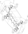
- FIG. 1 is a schematic diagram of a structure of a vehicle according to an embodiment of this application.
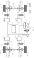
- FIG. 2 is a schematic diagram of a connection of a suspension system of a vehicle according to an embodiment of this application.
- the vehicle provided in this application includes a vehicle body 100, wheel shafts 300, wheels 200, and a suspension system.
- the wheels 200 are installed on the wheel shafts 300, and the suspension system is installed between the wheel shafts 300 and the vehicle body 100.
- the suspension system includes suspension assemblies 1, drivers 2, a controller 3, a compressor 4, and a gas tank 5.
- the gas tank 5, the compressor 4, and the suspension assemblies 1 are sequentially connected in series through ventilation pipes.
- the gas tank 5 is connected to the compressor 4 through a first ventilation pipe 6, and a first switch valve 7 is disposed on the first ventilation pipe 6.
- the compressor 4 is connected to the suspension assemblies 1 through second ventilation pipes 8, and a second switch valve 9 is disposed on each second ventilation pipe 8.
- gas in the gas tank 5 may flow into the suspension assembly 1 through the first ventilation pipe 6, the compressor 4, and the second ventilation pipe 8 in sequence under the action of the compressor 4, to drive the suspension assembly 1 to work.
- the suspension assemblies 1 each include a gas spring 101 and a height sensor 103.
- the compressor 4 is specifically connected to the gas spring 101 of the suspension assembly 1 through the second ventilation pipe 8, to control a height of the gas spring 101, so that distances between the vehicle body 100 and the wheels 200 are kept within a specific range. This improves stability and comfort of the vehicle body 100 in a running process of a user vehicle.
- the controller 3 is electrically connected to the driver 2, so that signal transmission can be performed between the controller 3 and the driver 2.
- the driver 2 is further separately electrically connected to the compressor 4, the first switch valve 7, and the second switch valve 9, and the controller 3 is electrically connected to the height sensor 103.
- the controller 3 is configured to: receive a height signal of the height sensor 103, generate a control signal based on the height signal, and transfer the control signal to the driver 2.
- the driver 2 is configured to: drive, based on the control signal of the controller 3, the first switch valve 7 and the second switch valve 9 to open or close, and control the compressor 4 to transmit gas to the gas spring 101 or stop transmitting gas.
- the height sensor 103 detects a detected height between the vehicle body 100 and the axle 300 at any time, to generate a height signal.
- the controller 3 may receive the height signal of the height sensor 103.
- the controller 3 compares the received height signal with a target signal of a target height. When the detected height is less than the target height, it is determined that a height of the vehicle body 100 needs to increase, that is, the gas spring 101 needs to be inflated.
- the control signal generated by the controller 3 is a gas filling signal, and the gas filling signal indicates to inflate the gas spring 101.
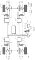
- FIG. 3 is a schematic diagram of a gas filling process of a suspension system of a vehicle according to an embodiment of this application. As shown in FIG.
- a controller 3 transfers the gas filling signal to drivers 2, and the drivers 2 drive, based on the gas filling signal, a first switch valve 7 and second switch valves 9 to open, so that ventilation pipes between gas springs 101 and a gas tank 5 communicate with each other.
- a first ventilation pipe 6 and second ventilation pipes 8 communicate with each other.
- the drivers 2 drive a compressor 4 to transport gas in the gas tank 5 to the gas springs 101, to inflate the gas springs 101. It may be considered that the compressor 4 runs in a forward direction in this working state.
- the controller 3 controls the drivers 2 to drive the first switch valve 7 and the second switch valves 9 to close, and drive the compressor 4 to stop running, to stop the gas filling process of the gas springs 101.
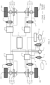
- FIG. 4 is a schematic diagram of a gas release process of a suspension system of a vehicle according to an embodiment of this application. As shown in FIG.
- a controller 3 transfers the gas release signal to drivers 2, and the drivers 2 drive, based on the gas release signal, a first switch valve 7 and second switch valves 9 to open, so that ventilation pipes between gas springs 101 and a gas tank 5 communicate with each other, in other words, a first ventilation pipe 6 and second ventilation pipes 8 communicate with each other.
- the drivers 2 drive a compressor 4 to transport gas in the gas springs 101 to the gas tank 5, to release gas in the gas springs 101. It may be considered that the compressor 4 runs in a reverse direction in this working state.
- the controller 3 controls the drivers 2 to drive the first switch valve 7 and the second switch valves 9 to close, and drive the compressor 4 to stop running, to stop the gas release process of the gas springs 101.
- the gas tank 5 is used to store gas
- the compressor 4 transports the gas in the gas tank 5 to the gas springs 101, and releases the gas in the gas springs 101 to the gas tank 5.
- a pressure change of the gas is small, that is, a rise amount of and a fall amount of gas pressure is small. Therefore, the gas filling process and gas release process take long time, and lifting and lowering speeds of the vehicle body 100 are fast.
- the compressor 4 also requires low power, and both noise and power consumption are low.
- structures such as the controller 3, the driver 2, the first switch valve 7, and the second switch valve 9 are independent structures. Therefore, the structures can be separately manufactured and installed, and costs are low.
- the controller 3 may be further configured to control another system in addition to the suspension system.
- the controller 3 receives height signals of the height sensors 103, so that the controller 3 may be directly connected to the height sensors 103, and receive the height signals.
- the drivers 2 may be connected to the height sensors 103, and the drivers 2 obtain the height signals and transfers the height signals to the controller 3.
- that the controller 3 is electrically connected to the height sensors 103 may mean that the controller 3 is directly connected to the height sensors 103, or may mean that the controller 3 is connected to the height sensors 103 through the drivers 2.
- the suspension assemblies 1 each further include a shock absorber 102.
- the driver 2 is connected to the shock absorber 102, and the driver 2 is configured to control, based on the control signal of the controller 3, the shock absorber 102 to adjust a damping force.
- the damping force of the shock absorber 102 may be adjusted while a height of the gas spring is adjusted.
- the shock absorber may adjust the damping force based on an actual running status of the vehicle. This improves comfort of a user.
- the vehicle includes a plurality of systems.
- the vehicle may further include a plurality of systems such as a braking system, a steering system, or an auxiliary driving system.
- the controller 3 may be a system controller, that is, the system controller may be only configured to control working of the suspension system, and is not associated with another system.
- the controller 3 may be a domain controller, and the domain controller is configured to control some of the plurality of systems of the vehicle. That is, the domain controller is configured to control at least two systems of the vehicle, rather than all the systems of the vehicle. In this solution, sharing of the controller 3 of the vehicle is improved, so that the controller 3 is moved upward. This reduces a total quantity of system controllers included in the vehicle.
- the controller 3 may alternatively be a vehicle controller.
- the vehicle controller is configured to control all the systems of the vehicle, to implement unified control and meet a current development requirement of the vehicle.
- FIG. 5 is a schematic diagram of a connection of another suspension system of a vehicle in an embodiment of this application.
- the compressor 4 is further connected to a third ventilation pipe 10, and the third ventilation pipe 10 opens to the outside atmosphere.
- a third switch valve 11 is disposed on the third ventilation pipe 10.
- the controller 3 may receive a gas filling instruction, control, based on the gas filling instruction, the third switch valve 11 to open, and control the compressor 4 to compress air and then transmit the compressed air to the gas tank 5.
- Slow leakage of gas is prone to occur during use of the suspension system. Consequently, there is a small amount of gas in the suspension system.
- the suspension system can fill gas by the suspension system, to keep total gas in the suspension system sufficient. This ensures reliability of the suspension system.
- the first switch valve 7 is a three-way valve.
- the gas tank 5 In a first working state of the three-way valve, the gas tank 5 is connected to a first ventilation opening of the compressor 4, and the first ventilation opening communicates with gas springs 101, and is configured to inflate or release gas for the gas springs 101.
- the gas tank 5 In a second working state of the three-way valve, the gas tank 5 is connected to a second ventilation opening of the compressor 4, and the second ventilation opening communicates with the third ventilation pipe 10, to implement gas filling of the gas tank 5.
- the three-way valve In a third working state of the three-way valve, the three-way valve is in a closed state. In this case, gas cannot flow into or flow out of the gas tank 5.
- the driver 2 is electrically connected to the controller 3, the compressor 4, a pressure sensor 12, the three-way valve, and the third switch valve 11.
- the controller 3 may receive a gas filling instruction, generate a gas filling signal, and transfer the gas filling signal to the driver 2.
- the driver 2 is configured to: control, based on the gas filling signal, the three-way valve to be in the second working state, drive the third switch valve 11 to open, and drive the compressor 4 to compress air and then transmit the compressed air to the gas tank 5, to implement gas filling of the suspension system.
- a user may actively fill gas.
- the controller 3 of the suspension system may be connected to a control button, and the user may periodically or irregularly send a gas filling instruction to the controller 3 by operating the control button.
- the controller 3 receives the gas filling instruction of the control button, generates a gas filling signal, and transfers the gas filling signal to the driver 2.
- the driver 2 implements gas filling of the suspension system based on the gas filling signal.
- the controller 3 may be further enabled to periodically fill the suspension system with gas, that is, the controller 3 periodically generates a gas filling signal, to control the driver 2 to fill the suspension system with gas based on the gas filling signal.
- the suspension system may further include the pressure sensor 12.
- the pressure sensor 12 is connected to the gas tank 5 and may be configured to detect pressure in the gas tank 5, to determine whether gas filling is required.
- the pressure sensor 12 is electrically connected to the controller 3, and the controller 3 is configured to: obtain a pressure signal of the pressure sensor 12, generate a gas filling signal based on the pressure signal, and transfer the gas filling signal to the driver 2.
- the driver 2 drives, based on the gas filling signal of the controller 3, the suspension system to automatically perform gas filling.
- This solution can implement automatic gas filling of the suspension system and avoid frequent manual gas filling.
- the controller 3 receives the pressure signal of the pressure sensor 12, so that the controller 3 may be directly connected to the pressure sensor 12 and receive the pressure signal.
- the driver 2 may be connected to the pressure sensor 12, and the driver 2 obtains the pressure signal, and transfers the pressure signal to the controller 3.
- that the controller 3 is electrically connected to the pressure sensor 12 may mean that the controller 3 is directly connected to the pressure sensor 12, or may mean that the controller 3 is connected to the pressure sensor 12 through the driver 2.
- the suspension system may include at least two suspension assemblies 1, and a gas spring 101 in each suspension assembly 1 is connected to one second switch valve 9.
- the second switch valve 9 of each suspension assembly 1 may be of an independent structure, to facilitate control of each gas spring 101.
- Each suspension system is further correspondingly provided with one driver 2.
- the driver 2 may be disposed close to the second switch valve 9, to reduce a cable harness and facilitate cabling of the suspension system.
- the second switch valves 9 of all the suspension assemblies 1 are of an integrated structure. This helps reduce volumes of the suspension assemblies 1.
- the suspension system includes four suspension assemblies 1, and the four suspension assemblies 1 are disposed in a matrix.
- the four suspension assemblies 1 are disposed in a matrix, so that the suspension assemblies 1 are disposed at all four corners of the vehicle, and heights of the vehicle body 100 at the four corners can be adjusted.
- the four suspension assemblies 1 do not need to be simultaneously driven, and the corresponding gas springs 101 may be controlled, based on signals of the corresponding height sensors 103, to perform gas filling and gas release, to improve stability and comfort of the vehicle.
- the vehicle includes a plurality of suspension assemblies 1, and the plurality of suspension assemblies 1 are disposed in a one-to-one correspondence with the wheels 200 of the vehicle, so that a height between each wheel 200 and the vehicle body 100 can be adjusted. This improves stability and comfort of the vehicle.
- FIG. 6 is a flowchart of a control method of a suspension system according to an embodiment of this application. As shown in FIG. 6 , the control method specifically includes the following steps.
- Step S101 Receive a height signal of a height sensor.
- the height sensor may detect a detection height between a vehicle body and an axle at any time. In a driving process of a vehicle, the height between the vehicle body and the axle needs to be maintained at a specific level, so that a form state of the vehicle can be stable.
- Step S102 Compare the height signal with a target height; and when the height signal is less than the target height, perform step S103; when the height signal is greater than the target height, perform step S104; or when the height signal is equal to the target height, perform step S105.
- the target height may be a specific height value, or may be a height range value. That the height signal is equal to the target height means that the height signal is within the height range value.
- Step S103 Control a first switch valve and a second switch valve to open, and control a compressor to drive, in a forward rotation manner, gas in a gas tank to flow into the gas spring, so that the height of the gas spring is increased, and the height between the vehicle body and the axle is increased.
- Step S104 Control a first switch valve and a second switch valve to open, and control a compressor to drive, in a reverse rotation manner, gas in the gas spring to flow into a gas tank, so that the height of the gas spring is reduced, and the height between the vehicle body and the axle is reduced.
- Step S105 Control a first switch valve and a second switch valve to close, so that the height of the gas spring remains unchanged, and the height between the vehicle body and the axle remains unchanged.
- the suspension system of the vehicle can automatically adjust the height between the vehicle body and the axle, to improve stability of the vehicle in a running process.
- the compressor may also be connected to a third ventilation pipe, and the third ventilation pipe opens to the outside atmosphere, so that the compressor can compress air in the atmosphere and transmit the compressed air to the gas tank during working, to fill the gas tank with gas.
- a specific gas filling control method includes: receiving a gas filling signal, controlling, based on the gas filling signal, the first switch valve and a third switch valve to open, and controlling the compressor to compress air and then transmit the compressed air to the gas tank.
- the third switch valve is closed when there is no need to fill gas, so that gas in the suspension system is kept circulating internally and does not leak from the third ventilation pipe.
- the suspension system can automatically perform gas filling, to keep a sufficient amount of gas in the suspension system to maintain normal working.
- a manner of triggering the gas filling signal is not limited.
- a controller of the suspension system may be connected to a control button, and a user may periodically or irregularly send a gas filling signal instruction to the controller by operating the control button.
- the controller receives the gas filling instruction of the control button, generates a gas filling signal, and implements gas filling of the suspension system based on the gas filling signal.
- the controller may be enabled to periodically fill the suspension system with gas, that is, the controller periodically generates a gas filling signal, to fill the suspension system with gas based on the gas filling signal.
- the suspension system may further include a pressure sensor.
- the pressure sensor is connected to the gas tank and is configured to detect pressure in the gas tank.
- the control method further includes: obtaining pressure detected by the pressure sensor, and when the pressure is less than specified pressure, determining that gas in the gas tank is insufficient, and generating a gas filling signal; and controlling, based on the gas filling signal, the first switch valve and the third switch valve to open, and controlling the compressor to compress air and then transmit the compressed air to the gas tank.
- gas filling may be performed at any time based on an actual gas situation in the gas tank, to ensure working reliability of the suspension system and avoid a useless gas filling operation.
Landscapes
- Engineering & Computer Science (AREA)
- Mechanical Engineering (AREA)
- Vehicle Body Suspensions (AREA)
Abstract
Description
- This application relates to the field of vehicle structure technologies, and in particular, to a suspension system and a control method thereof, and a vehicle.
- A suspension system of an automobile is connected between a sprung mass and an unsprung mass. This can weaken disturbance of road excitation to an output variable of the automobile. An output of the automobile is generally considered from two aspects: comfort and road adhesion, and corresponding output variables of the automobile are respectively an acceleration of an automobile body and deformation of tires. There is a contradiction between the acceleration of the automobile body and the deformation of the tires. In the suspension system of the automobile, a compromise between the acceleration of the automobile body and the deformation of the tires needs to be measured when suspension travel and design costs are considered, so that the automobile in a driving state can appropriately respond to requirements of a driver or vehicle design, to meet requirements of comfort, maneuverability, and safety design. The suspension system of the automobile usually includes a passive suspension system, a semi-active suspension system, and a full active suspension system.
- The passive suspension system is a mainstream suspension system for a long time period because of an advantage of low costs. As electronic control technologies develop, the semi-active suspension system is gradually favored by the market because of controllability and adaptive adjustment, and is equipped on more models of automobiles. The semi-active suspension system usually includes a spiral spring or gas spring and a damper whose damping can be adjusted continuously. An active suspension is equipped on a few top-level models of automobiles, and needs additional energy inputs such as a hydraulic pump and a linear motor to implement an active actuation operation.
- A current semi-active air suspension system usually undergoes gas filling and release by using a semi-active shock absorber as a damping element and a gas spring as an elastic element to adjust a height characteristic of the current semi-active air suspension system, to meet different external input requirements. In the conventional technology, in terms of a gas path of the gas spring, a gas pump is mainly used to supply gas from the atmosphere to the gas spring, and the gas is directly discharged into the atmosphere during exhaust, to implement extension and compression of the gas spring. In this open-loop solution of the gas path, because air with low atmospheric pressure needs to be pressurized to specific pressure, pressure changes greatly. Therefore, long time is consumed, and lifting and lowering speeds of an automobile body are low. In addition, because the air needs to be pressurized to specific pressure, high power of an air compressor is required, and noise is loud.
- This application provides a suspension system and a control method thereof, and a vehicle. If gas pressure in a gas path system of the suspension system changes slightly, a speed of adjusting a height of a gas spring is fast, power of a compressor of the suspension system is low, and noise and power consumption are low. In addition, in a technical solution of this application, each part has an independent structure, and may be separately manufactured and installed, and therefore, costs are low. This helps move a controller upward, to implement unified control of the entire vehicle.
- According to a first aspect, this application provides a suspension system. The suspension system includes a suspension assembly, a driver, a controller, a compressor, and a gas tank. The suspension assembly has a gas spring and a height sensor. The gas tank is provided with gas, the gas tank is connected to the compressor through a first ventilation pipe, and the compressor is connected to the gas spring through a second ventilation pipe. In this case, the compressor may transfer gas in the gas tank to the gas spring, or transfer gas in the gas spring to the gas tank. In a specific technical solution, a first switch valve is disposed on the first ventilation pipe, and a second switch valve is disposed on the second ventilation pipe. Therefore, opening or closing of the first switch valve and the second switch valve is controlled, so that an entire gas path can be ventilated or closed. The driver is separately electrically connected to the controller, the compressor, the first switch valve, and the second switch valve, and the controller is electrically connected to the height sensor. The suspension system may be installed between a wheel of a vehicle and a vehicle body. In a working process of the suspension system, the height sensor is configured to detect a distance between the wheel and the vehicle body, and the controller is configured to: receive a height signal of the height sensor, generate a control signal based on the height signal, and transfer the control signal to the driver. After receiving the control signal, the driver is configured to: control, based on the control signal, the first switch valve and the second switch valve to open or close, and control the compressor to transmit gas to the gas spring or stop transmitting gas.
- The gas path system of the suspension system in the technical solution of this application includes a gas tank for storing gas, and gas in the gas tank has specific pressure. Compared with gas pressure required in the gas spring, the gas pressure in the gas tank changes slightly. Therefore, a height of the gas spring is adjusted at a high speed, power of the compressor of the suspension system is low, and noise and power consumption are also low. In addition, in a technical solution of this application, each part has an independent structure, and may be separately manufactured and installed, and therefore, costs are low. This helps move a controller upward, to implement unified control of the entire vehicle.
- It should be noted that the controller receives the height signal of the height sensor, so that the controller may be directly connected to the height sensor and receive the height signal. Alternatively, the driver may be connected to the height sensor, and the driver obtains the height signal, and transfers the height signal to the controller. In other words, that the controller is electrically connected to the height sensor may mean that the controller is directly connected to the height sensor, or may mean that the controller is connected to the height sensor through the driver.
- In a specific technical solution, the suspension assembly further includes a shock absorber. The driver is connected to the shock absorber, and the driver is configured to control, based on the control signal of the controller, the shock absorber to adjust a damping force. In the technical solution of this application, the shock absorber may adjust the damping force based on an actual running status of the vehicle. This improves comfort of a user.
- The compressor is further connected to a third ventilation pipe, and the third ventilation pipe opens to the outside atmosphere, so that the compressor can compress air in the atmosphere and transmit the compressed air to the gas tank during working, to fill the gas tank with gas. A third switch valve is disposed on the third ventilation pipe, and the third switch valve is enabled to open only when gas filling is required. The third switch valve is closed when there is no need to fill gas, so that gas in a suspension system is kept circulating internally and does not leak from the third ventilation pipe. In this technical solution, the suspension system may fill gas by the suspension system, to keep a sufficient amount of gas in the suspension system to maintain normal working. A specific manner of filling the gas tank with gas is not limited in this application. For example, the third switch valve may also be connected to the driver, and the driver is connected to the controller. The controller may be connected to a control button, and a user presses the control button according to a requirement, to fill gas. Alternatively, the controller may control periodical gas filling.
- Alternatively, in still another specific technical solution, the suspension system may further include a pressure sensor. The pressure sensor is connected to the gas tank and is configured to detect pressure in the gas tank. The first switch valve is a three-way valve, configured to transmit gas in the gas tank to the gas spring, and configured to transmit gas from the atmosphere to the gas tank. The driver is electrically connected to the compressor, the three-way valve, and the third switch valve, and the controller is electrically connected to the pressure sensor. The controller is configured to: obtain a pressure signal of the pressure sensor, and generate a gas filling signal based on the pressure signal. Specifically, when pressure detected by the pressure sensor is lower than specified pressure, it may be considered that the gas in the gas tank is insufficient, and gas filling is required. The driver obtains the gas filling signal generated by the controller, drives, based on the gas filling signal, the three-way valve to connect the compressor and the gas tank, drives the third switch valve to open, and drives the compressor to compress air and then transmit the compressed air to the gas tank. In this solution, gas filling may be performed based on an actual gas condition in the gas tank. When it is found that the gas in the gas tank is insufficient, gas filling may be performed at any time, to ensure working reliability of the suspension system, and avoid a useless gas filling operation.
- It should be noted that the controller receives the pressure signal of the pressure sensor, so that the controller may be directly connected to the pressure sensor and receive the pressure signal. Alternatively, the driver may be connected to the pressure sensor, and the driver obtains the pressure signal, and transfers the pressure signal to the controller. In other words, that the controller is electrically connected to the pressure sensor may mean that the controller is directly connected to the pressure sensor, or may mean that the controller is connected to the pressure sensor through the driver.
- A quantity of suspension assemblies included in the suspension system is not limited, and the suspension system includes at least two suspension assemblies. A gas spring in each suspension assembly is connected to one second switch valve. In this solution, the at least two suspension assemblies may adjust heights of positions at which the at least two suspension assemblies are located, and may be separately controlled. This improves stability and comfort of the vehicle.
- In the foregoing embodiment, all second switch valves are of an integrated structure, to reduce space occupied by the second switch valves.
- In addition, when the suspension system includes the at least two suspension assemblies, each suspension assembly is correspondingly provided with one driver, so that a distance between the driver and a corresponding suspension assembly is short, to reduce a cable harness and facilitate cabling of the suspension system.
- In a specific technical solution, the suspension system may include four suspension assemblies. The four suspension assemblies are disposed in a matrix, so that the suspension assemblies may be disposed at all four corners of the vehicle, to adjust heights of the vehicle body at the four corners.
- Specifically, the four suspension assemblies do not need to be simultaneously driven, and the corresponding gas springs may be controlled, based on signals of the corresponding height sensors, to perform gas filling and gas release, to improve stability and comfort of the vehicle.
- In the technical solution of this application, the controller, the driver, and the first switch valve are split structures. In this case, in addition to being a system controller, the controller may be a domain controller or a vehicle controller. The vehicle usually includes a plurality of control systems, and the domain controller means that the controller may control at least two of the plurality of control systems. The vehicle controller can control all control systems.
- According to a second aspect, this application further provides a control method of the suspension system in the first aspect. The control method specifically includes: receiving a height signal of a height sensor; comparing the height signal with a target height; and when the height signal is less than the target height, indicating that a height of a gas spring needs to increase, controlling a first switch valve and a second switch valve to open, and controlling a compressor to drive, in a forward rotation manner, gas in a gas tank to flow into the gas spring, so that the height of the gas spring increases; when the height signal is greater than the target height, indicating that the height of the gas spring needs to be reduced, controlling the first switch valve and the second switch valve to open, and controlling the compressor to drive, in a reverse rotation manner, gas in the gas spring to flow into the gas tank, so that the height of the gas spring is reduced; or when the height signal is equal to the target height, controlling the first switch valve and the second switch valve to close. The method can be used to implement gas filling and gas release processes of the suspension system. In this solution, the gas tank is used to load gas, and power of the compressor of the suspension system is low, and noise and power consumption are also low. It should be noted that, in this embodiment of this application, the target height may be a specific height value, or may be a height range value. That the height signal is equal to the target height means that the height signal is within the height range value.
- The compressor may also be connected to a third ventilation pipe, and the third ventilation pipe opens to the outside atmosphere, so that the compressor can compress air in the atmosphere and transmit the compressed air to the gas tank during working, to fill the gas tank with gas. A specific gas filling control method includes: controlling the first switch valve and a third switch valve to open, and controlling the compressor to compress air and then transmit the compressed air to the gas tank. The third switch valve is closed when there is no need to fill gas, so that gas in the suspension system is kept circulating internally and does not leak from the third ventilation pipe. In this technical solution, the suspension system can perform gas filling by the suspension system, to keep a sufficient amount of gas in the suspension system to maintain normal working.
- The suspension system may further include a pressure sensor. The pressure sensor is connected to the gas tank and is configured to detect pressure in the gas tank. The control method further includes: obtaining pressure detected by the pressure sensor, and when the pressure is less than specified pressure, considering that gas in the gas tank is insufficient, and generating a gas filling signal; and controlling, based on the gas filling signal, the first switch valve and the third switch valve to open, and controlling the compressor to compress air and then transmit the compressed air to the gas tank. In this solution, when it is found that the gas in the gas tank is insufficient, gas filling may be performed at any time based on an actual gas condition in the gas tank, to ensure working reliability of the suspension system, and avoid a useless gas filling operation. According to a third aspect, this application further provides a vehicle. The vehicle includes a vehicle body, a wheel shaft, wheels, and the suspension system in any one of the foregoing technical solutions. The wheels are installed on the wheel shaft, and the suspension system is installed between the wheel shaft and the vehicle body. The suspension system of the vehicle adjusts a height of a gas spring at a high speed, and power of a compressor of the suspension system is low. Therefore, a corresponding speed of the vehicle for a bumpy road surface or the like is also fast, and noise and power consumption are also low. In addition, in the technical solution of this application, structures such as a controller and a driver are independent structures, and may be separately manufactured and installed, and therefore, costs are low. This helps move the controller upward, to implement unified control of the entire vehicle.
- In a specific technical solution, the controller may be a domain controller. The vehicle includes a plurality of systems, and some of the plurality of systems share the domain controller. In other words, the domain controller can control at least two systems of the vehicle.
- In addition, the controller is a vehicle controller. The vehicle includes a plurality of systems, and all the systems share the vehicle controller. In this solution, one vehicle controller can control all the systems.
- During specific arrangement of the suspension system, the suspension system may include a plurality of suspension assemblies, and the plurality of suspension assemblies are disposed in a one-to-one correspondence with the wheels of the vehicle. Therefore, stability of the vehicle in a running process can be improved, and comfort of a user can be improved.
-
-
FIG. 1 is a schematic diagram of a structure of a vehicle according to an embodiment of this application; -
FIG. 2 is a schematic diagram of a connection of a suspension system of a vehicle according to an embodiment of this application; -
FIG. 3 is a schematic diagram of a gas filling process of a suspension system of a vehicle according to an embodiment of this application; -
FIG. 4 is a schematic diagram of a gas release process of a suspension system of a vehicle according to an embodiment of this application; -
FIG. 5 is a schematic diagram of a connection of another suspension system of a vehicle in an embodiment of this application; and -
FIG. 6 is a flowchart of a control method of a suspension system according to an embodiment of this application. -
- 100: vehicle body; 200: wheel;
- 300: wheel shaft; 1: suspension assembly;
- 101: gas spring; 102: shock absorber;
- 103: height sensor; 2: driver;
- 3: controller; 4: compressor;
- 5: gas tank; 6: first ventilation pipe;
- 7: first switch valve; 8: second ventilation pipe;
- 9: second switch valve; 10: third ventilation pipe;
- 11: third switch valve; 12: pressure sensor.
- For ease of understanding, embodiments of this application provide a suspension system and a control method thereof, and a vehicle. The following describes application scenarios of the suspension system and the control method thereof, and the vehicle. Currently, people have an increasingly high requirement for comfort in a driving process of a vehicle, and requirements such as safety and maneuverability need to be met. The suspension system of the vehicle can better improve comfort of the vehicle. Specifically, the suspension system is connected between a sprung mass and an unsprung mass of the vehicle. The sprung mass may be understood as a vehicle body, namely, structural space described by a user, and the unsprung mass may be understood as a structure like a wheel. Especially for an active air suspension system, the air suspension system is formed by a gas spring and a shock absorber. A controller may drive the gas spring and the shock absorber to work based on a current state of the vehicle, and adjust a height of the vehicle and damping of the shock absorber. When the vehicle continuously travels on a bumpy road, the controller may control and drive the gas spring and the shock absorber to work, and adjust a height between the sprung mass and the unsprung mass, so that the height between the sprung mass and the unsprung mass reaches a set height. In addition, the shock absorber outputs an optimal damping force, to improve comfort of the user. However, in the conventional technology, to resolve problems such as loud noise and a slow response speed in an open-loop solution of a gas path, a closed-loop solution of the gas path is proposed. In the closed-loop solution of the gas path, a controller, a driver, and a valve are of an integrated structure. Therefore, there are problems such as a high coupling degree, a large manufacturing difficulty, and high costs. In addition, the controller can only be used as an independent controller to control the suspension system. This is not conducive to integration of the vehicle.
- The following describes in detail embodiments of this application with reference to accompanying drawings. Terms used in the following embodiments are merely intended to describe specific embodiments, but are not intended to limit this application. The terms "one", "a", and "this" of singular forms used in this specification and the appended claims of this application are also intended to include expressions such as "one or more", unless otherwise specified in the context clearly.
- Reference to "an embodiment", "a specific embodiment", or the like described in this specification indicates that one or more embodiments of this application include a specific feature, structure, or characteristic described with reference to the embodiment. Terms "include", "have", and their variants all mean "include but are not limited to", unless otherwise specifically emphasized in another manner.
-
FIG. 1 is a schematic diagram of a structure of a vehicle according to an embodiment of this application.FIG. 2 is a schematic diagram of a connection of a suspension system of a vehicle according to an embodiment of this application. As shown inFIG. 1 andFIG. 2 , the vehicle provided in this application includes avehicle body 100,wheel shafts 300,wheels 200, and a suspension system. Thewheels 200 are installed on thewheel shafts 300, and the suspension system is installed between thewheel shafts 300 and thevehicle body 100. In a specific technical solution, the suspension system includessuspension assemblies 1,drivers 2, acontroller 3, acompressor 4, and agas tank 5. Thegas tank 5, thecompressor 4, and thesuspension assemblies 1 are sequentially connected in series through ventilation pipes. Specifically, thegas tank 5 is connected to thecompressor 4 through afirst ventilation pipe 6, and afirst switch valve 7 is disposed on thefirst ventilation pipe 6. Thecompressor 4 is connected to thesuspension assemblies 1 throughsecond ventilation pipes 8, and asecond switch valve 9 is disposed on eachsecond ventilation pipe 8. When thefirst switch valve 7 and thesecond switch valve 9 are in an open state, gas in thegas tank 5 may flow into thesuspension assembly 1 through thefirst ventilation pipe 6, thecompressor 4, and thesecond ventilation pipe 8 in sequence under the action of thecompressor 4, to drive thesuspension assembly 1 to work. - Specifically, the
suspension assemblies 1 each include agas spring 101 and aheight sensor 103. Thecompressor 4 is specifically connected to thegas spring 101 of thesuspension assembly 1 through thesecond ventilation pipe 8, to control a height of thegas spring 101, so that distances between thevehicle body 100 and thewheels 200 are kept within a specific range. This improves stability and comfort of thevehicle body 100 in a running process of a user vehicle. Thecontroller 3 is electrically connected to thedriver 2, so that signal transmission can be performed between thecontroller 3 and thedriver 2. In addition, thedriver 2 is further separately electrically connected to thecompressor 4, thefirst switch valve 7, and thesecond switch valve 9, and thecontroller 3 is electrically connected to theheight sensor 103. Thecontroller 3 is configured to: receive a height signal of theheight sensor 103, generate a control signal based on the height signal, and transfer the control signal to thedriver 2. Thedriver 2 is configured to: drive, based on the control signal of thecontroller 3, thefirst switch valve 7 and thesecond switch valve 9 to open or close, and control thecompressor 4 to transmit gas to thegas spring 101 or stop transmitting gas. - In a specific application process of the suspension system, the
height sensor 103 detects a detected height between thevehicle body 100 and theaxle 300 at any time, to generate a height signal. Thecontroller 3 may receive the height signal of theheight sensor 103. Thecontroller 3 compares the received height signal with a target signal of a target height. When the detected height is less than the target height, it is determined that a height of thevehicle body 100 needs to increase, that is, thegas spring 101 needs to be inflated. In this case, the control signal generated by thecontroller 3 is a gas filling signal, and the gas filling signal indicates to inflate thegas spring 101.FIG. 3 is a schematic diagram of a gas filling process of a suspension system of a vehicle according to an embodiment of this application. As shown inFIG. 3 , acontroller 3 transfers the gas filling signal todrivers 2, and thedrivers 2 drive, based on the gas filling signal, afirst switch valve 7 andsecond switch valves 9 to open, so that ventilation pipes between gas springs 101 and agas tank 5 communicate with each other. To be specific, afirst ventilation pipe 6 andsecond ventilation pipes 8 communicate with each other. In addition, thedrivers 2 drive acompressor 4 to transport gas in thegas tank 5 to the gas springs 101, to inflate the gas springs 101. It may be considered that thecompressor 4 runs in a forward direction in this working state. When detected heights detected byheight sensors 103 are the same as a target height, thecontroller 3 controls thedrivers 2 to drive thefirst switch valve 7 and thesecond switch valves 9 to close, and drive thecompressor 4 to stop running, to stop the gas filling process of the gas springs 101. - When the detected heights are greater than the target height, it is determined that a height of a
vehicle body 100 needs to be lowered, and gas release needs to be performed on the gas springs 101. In this case, a control signal generated by thecontroller 3 is a gas release signal, and the gas release signal indicates to perform gas release on the gas springs 101.FIG. 4 is a schematic diagram of a gas release process of a suspension system of a vehicle according to an embodiment of this application. As shown inFIG. 4 , acontroller 3 transfers the gas release signal todrivers 2, and thedrivers 2 drive, based on the gas release signal, afirst switch valve 7 andsecond switch valves 9 to open, so that ventilation pipes between gas springs 101 and agas tank 5 communicate with each other, in other words, afirst ventilation pipe 6 andsecond ventilation pipes 8 communicate with each other. In addition, thedrivers 2 drive acompressor 4 to transport gas in the gas springs 101 to thegas tank 5, to release gas in the gas springs 101. It may be considered that thecompressor 4 runs in a reverse direction in this working state. When detected heights detected byheight sensors 103 are the same as a target height, thecontroller 3 controls thedrivers 2 to drive thefirst switch valve 7 and thesecond switch valves 9 to close, and drive thecompressor 4 to stop running, to stop the gas release process of the gas springs 101. - In the technical solution of this application, the
gas tank 5 is used to store gas, thecompressor 4 transports the gas in thegas tank 5 to the gas springs 101, and releases the gas in the gas springs 101 to thegas tank 5. In this solution, a pressure change of the gas is small, that is, a rise amount of and a fall amount of gas pressure is small. Therefore, the gas filling process and gas release process take long time, and lifting and lowering speeds of thevehicle body 100 are fast. In addition, thecompressor 4 also requires low power, and both noise and power consumption are low. In addition, in the technical solution of this application, structures such as thecontroller 3, thedriver 2, thefirst switch valve 7, and thesecond switch valve 9 are independent structures. Therefore, the structures can be separately manufactured and installed, and costs are low. In addition, thecontroller 3 may be further configured to control another system in addition to the suspension system. - It should be noted that the
controller 3 receives height signals of theheight sensors 103, so that thecontroller 3 may be directly connected to theheight sensors 103, and receive the height signals. Alternatively, thedrivers 2 may be connected to theheight sensors 103, and thedrivers 2 obtain the height signals and transfers the height signals to thecontroller 3. In other words, that thecontroller 3 is electrically connected to theheight sensors 103 may mean that thecontroller 3 is directly connected to theheight sensors 103, or may mean that thecontroller 3 is connected to theheight sensors 103 through thedrivers 2. - In a specific embodiment, the
suspension assemblies 1 each further include ashock absorber 102. Thedriver 2 is connected to theshock absorber 102, and thedriver 2 is configured to control, based on the control signal of thecontroller 3, theshock absorber 102 to adjust a damping force. Specifically, the damping force of theshock absorber 102 may be adjusted while a height of the gas spring is adjusted. In the technical solution of this application, the shock absorber may adjust the damping force based on an actual running status of the vehicle. This improves comfort of a user. - In a specific embodiment, the vehicle includes a plurality of systems. For example, in addition to the suspension system, the vehicle may further include a plurality of systems such as a braking system, a steering system, or an auxiliary driving system. In a specific embodiment, the
controller 3 may be a system controller, that is, the system controller may be only configured to control working of the suspension system, and is not associated with another system. - In another specific embodiment, the
controller 3 may be a domain controller, and the domain controller is configured to control some of the plurality of systems of the vehicle. That is, the domain controller is configured to control at least two systems of the vehicle, rather than all the systems of the vehicle. In this solution, sharing of thecontroller 3 of the vehicle is improved, so that thecontroller 3 is moved upward. This reduces a total quantity of system controllers included in the vehicle. - In still another specific embodiment, the
controller 3 may alternatively be a vehicle controller. The vehicle controller is configured to control all the systems of the vehicle, to implement unified control and meet a current development requirement of the vehicle. -
FIG. 5 is a schematic diagram of a connection of another suspension system of a vehicle in an embodiment of this application. As shown inFIG. 5 , in a further embodiment, thecompressor 4 is further connected to athird ventilation pipe 10, and thethird ventilation pipe 10 opens to the outside atmosphere. In addition, athird switch valve 11 is disposed on thethird ventilation pipe 10. In a specific working process, thecontroller 3 may receive a gas filling instruction, control, based on the gas filling instruction, thethird switch valve 11 to open, and control thecompressor 4 to compress air and then transmit the compressed air to thegas tank 5. Slow leakage of gas is prone to occur during use of the suspension system. Consequently, there is a small amount of gas in the suspension system. In this solution, the suspension system can fill gas by the suspension system, to keep total gas in the suspension system sufficient. This ensures reliability of the suspension system. - In a specific embodiment, the
first switch valve 7 is a three-way valve. In a first working state of the three-way valve, thegas tank 5 is connected to a first ventilation opening of thecompressor 4, and the first ventilation opening communicates withgas springs 101, and is configured to inflate or release gas for the gas springs 101. In a second working state of the three-way valve, thegas tank 5 is connected to a second ventilation opening of thecompressor 4, and the second ventilation opening communicates with thethird ventilation pipe 10, to implement gas filling of thegas tank 5. In a third working state of the three-way valve, the three-way valve is in a closed state. In this case, gas cannot flow into or flow out of thegas tank 5. Thedriver 2 is electrically connected to thecontroller 3, thecompressor 4, apressure sensor 12, the three-way valve, and thethird switch valve 11. Thecontroller 3 may receive a gas filling instruction, generate a gas filling signal, and transfer the gas filling signal to thedriver 2. Thedriver 2 is configured to: control, based on the gas filling signal, the three-way valve to be in the second working state, drive thethird switch valve 11 to open, and drive thecompressor 4 to compress air and then transmit the compressed air to thegas tank 5, to implement gas filling of the suspension system. - Specifically, when gas filling is performed on the suspension system, a user may actively fill gas. For example, the
controller 3 of the suspension system may be connected to a control button, and the user may periodically or irregularly send a gas filling instruction to thecontroller 3 by operating the control button. Thecontroller 3 receives the gas filling instruction of the control button, generates a gas filling signal, and transfers the gas filling signal to thedriver 2. Thedriver 2 implements gas filling of the suspension system based on the gas filling signal. - Alternatively, in another specific embodiment, the
controller 3 may be further enabled to periodically fill the suspension system with gas, that is, thecontroller 3 periodically generates a gas filling signal, to control thedriver 2 to fill the suspension system with gas based on the gas filling signal. - Alternatively, in a specific embodiment, the suspension system may further include the
pressure sensor 12. Thepressure sensor 12 is connected to thegas tank 5 and may be configured to detect pressure in thegas tank 5, to determine whether gas filling is required. Specifically, thepressure sensor 12 is electrically connected to thecontroller 3, and thecontroller 3 is configured to: obtain a pressure signal of thepressure sensor 12, generate a gas filling signal based on the pressure signal, and transfer the gas filling signal to thedriver 2. Thedriver 2 drives, based on the gas filling signal of thecontroller 3, the suspension system to automatically perform gas filling. This solution can implement automatic gas filling of the suspension system and avoid frequent manual gas filling. It should be noted that thecontroller 3 receives the pressure signal of thepressure sensor 12, so that thecontroller 3 may be directly connected to thepressure sensor 12 and receive the pressure signal. Alternatively, thedriver 2 may be connected to thepressure sensor 12, and thedriver 2 obtains the pressure signal, and transfers the pressure signal to thecontroller 3. In other words, that thecontroller 3 is electrically connected to thepressure sensor 12 may mean that thecontroller 3 is directly connected to thepressure sensor 12, or may mean that thecontroller 3 is connected to thepressure sensor 12 through thedriver 2. - In a specific embodiment, the suspension system may include at least two
suspension assemblies 1, and agas spring 101 in eachsuspension assembly 1 is connected to onesecond switch valve 9. In a specific technical solution, thesecond switch valve 9 of eachsuspension assembly 1 may be of an independent structure, to facilitate control of eachgas spring 101. - Each suspension system is further correspondingly provided with one
driver 2. Specifically, when thesecond switch valve 9 of eachsuspension assembly 1 and thedriver 2 are disposed, thedriver 2 may be disposed close to thesecond switch valve 9, to reduce a cable harness and facilitate cabling of the suspension system. - In a specific embodiment, the
second switch valves 9 of all thesuspension assemblies 1 are of an integrated structure. This helps reduce volumes of thesuspension assemblies 1. - Refer to
FIG. 1 . In a specific embodiment, the suspension system includes foursuspension assemblies 1, and the foursuspension assemblies 1 are disposed in a matrix. In this solution, the foursuspension assemblies 1 are disposed in a matrix, so that thesuspension assemblies 1 are disposed at all four corners of the vehicle, and heights of thevehicle body 100 at the four corners can be adjusted. Specifically, the foursuspension assemblies 1 do not need to be simultaneously driven, and the corresponding gas springs 101 may be controlled, based on signals of thecorresponding height sensors 103, to perform gas filling and gas release, to improve stability and comfort of the vehicle. - Specifically, the vehicle includes a plurality of
suspension assemblies 1, and the plurality ofsuspension assemblies 1 are disposed in a one-to-one correspondence with thewheels 200 of the vehicle, so that a height between eachwheel 200 and thevehicle body 100 can be adjusted. This improves stability and comfort of the vehicle. - Based on a same inventive concept, this application further provides a control method of a suspension system. The suspension system is specifically the suspension system in any one of the foregoing embodiments.
FIG. 6 is a flowchart of a control method of a suspension system according to an embodiment of this application. As shown inFIG. 6 , the control method specifically includes the following steps. - Step S101: Receive a height signal of a height sensor.
- The height sensor may detect a detection height between a vehicle body and an axle at any time. In a driving process of a vehicle, the height between the vehicle body and the axle needs to be maintained at a specific level, so that a form state of the vehicle can be stable.
- Step S102: Compare the height signal with a target height; and when the height signal is less than the target height, perform step S103; when the height signal is greater than the target height, perform step S104; or when the height signal is equal to the target height, perform step S105. When the height signal is less than the target height, it is considered that the height between the vehicle body and the axle is excessively low, and a height of a gas spring needs to increase, so that the height between the vehicle body and the axle meets the target height. When the height signal is greater than the target height, it is considered that the height between the vehicle body and the axle is excessively high, and the height of the gas spring needs to be reduced, so that the height between the vehicle body and the axle meets the target height. It should be noted that the target height may be a specific height value, or may be a height range value. That the height signal is equal to the target height means that the height signal is within the height range value.
- Step S103: Control a first switch valve and a second switch valve to open, and control a compressor to drive, in a forward rotation manner, gas in a gas tank to flow into the gas spring, so that the height of the gas spring is increased, and the height between the vehicle body and the axle is increased.
- Step S104: Control a first switch valve and a second switch valve to open, and control a compressor to drive, in a reverse rotation manner, gas in the gas spring to flow into a gas tank, so that the height of the gas spring is reduced, and the height between the vehicle body and the axle is reduced. Step S105: Control a first switch valve and a second switch valve to close, so that the height of the gas spring remains unchanged, and the height between the vehicle body and the axle remains unchanged.
- In the foregoing control process, the suspension system of the vehicle can automatically adjust the height between the vehicle body and the axle, to improve stability of the vehicle in a running process.
- The compressor may also be connected to a third ventilation pipe, and the third ventilation pipe opens to the outside atmosphere, so that the compressor can compress air in the atmosphere and transmit the compressed air to the gas tank during working, to fill the gas tank with gas. A specific gas filling control method includes: receiving a gas filling signal, controlling, based on the gas filling signal, the first switch valve and a third switch valve to open, and controlling the compressor to compress air and then transmit the compressed air to the gas tank. The third switch valve is closed when there is no need to fill gas, so that gas in the suspension system is kept circulating internally and does not leak from the third ventilation pipe. In this technical solution, the suspension system can automatically perform gas filling, to keep a sufficient amount of gas in the suspension system to maintain normal working.
- In a specific embodiment, a manner of triggering the gas filling signal is not limited. For example, a controller of the suspension system may be connected to a control button, and a user may periodically or irregularly send a gas filling signal instruction to the controller by operating the control button. The controller receives the gas filling instruction of the control button, generates a gas filling signal, and implements gas filling of the suspension system based on the gas filling signal. Alternatively, the controller may be enabled to periodically fill the suspension system with gas, that is, the controller periodically generates a gas filling signal, to fill the suspension system with gas based on the gas filling signal.
- Alternatively, the suspension system may further include a pressure sensor. The pressure sensor is connected to the gas tank and is configured to detect pressure in the gas tank. The control method further includes: obtaining pressure detected by the pressure sensor, and when the pressure is less than specified pressure, determining that gas in the gas tank is insufficient, and generating a gas filling signal; and controlling, based on the gas filling signal, the first switch valve and the third switch valve to open, and controlling the compressor to compress air and then transmit the compressed air to the gas tank. In this solution, when it is found that the gas in the gas tank is insufficient, gas filling may be performed at any time based on an actual gas situation in the gas tank, to ensure working reliability of the suspension system and avoid a useless gas filling operation.
- It is clear that a person skilled in the art can make various modifications and variations to this application without departing from the protection scope of this application. Thus, this application is intended to cover such modifications and variations to this application, provided that the modifications and variations fall within the scope of the claims of this application and their equivalent technologies.
Claims (16)
- A suspension system, comprising a suspension assembly, a driver, a controller, a compressor, and a gas tank, wherein the suspension assembly comprises a gas spring and a height sensor, whereinthe gas tank is connected to the compressor through a first ventilation pipe, and a first switch valve is disposed on the first ventilation pipe; the compressor is connected to the gas spring through a second ventilation pipe, and a second switch valve is disposed on the second ventilation pipe; the driver is separately electrically connected to the controller, the compressor, the first switch valve, and the second switch valve, and the controller is electrically connected to the height sensor; andthe controller is configured to: receive a height signal of the height sensor, generate a control signal based on the height signal, and transfer the control signal to the driver; and the driver is configured to: control, based on the control signal, the first switch valve and the second switch valve to open or close, and control the compressor to drive gas in the gas spring to flow into the gas tank, drive gas in the gas tank to flow into the gas spring, or stop transmitting gas.
- The suspension system according to claim 1, wherein the compressor is further connected to a third ventilation pipe, the third ventilation pipe opens to the outside atmosphere, and a third switch valve is disposed on the third ventilation pipe; and when the first switch valve and the third switch valve are in an open state, the compressor compresses air and then transmits the compressed air to the gas tank.
- The suspension system according to claim 2, wherein the gas tank is further connected to a pressure sensor, the first switch valve is a three-way valve, the driver is electrically connected to the compressor, the three-way valve, and the third switch valve, and the controller is electrically connected to the pressure sensor; and the controller is configured to: obtain a pressure signal of the pressure sensor, generate a gas filling signal based on the pressure signal, and transmit the gas filling signal to the driver, and the driver is configured to: drive, based on the gas filling signal, the three-way valve to connect the compressor and the gas tank, drive the third switch valve to open, and drive the compressor to compress air and then transmit the compressed air to the gas tank.
- The suspension system according to any one of claims 1 to 3, wherein the suspension assembly further comprises a shock absorber, the driver is also connected to the shock absorber, and the driver is further configured to control, based on the control signal of the controller, the shock absorber to adjust a damping force.
- The suspension system according to any one of claims 1 to 4, wherein the suspension system comprises at least two suspension assemblies, and a gas spring in each suspension assembly is connected to one second switch valve.
- The suspension system according to claim 5, wherein all second switch valves are of an integrated structure.
- The suspension system according to claim 5 or 6, wherein each suspension assembly is correspondingly provided with one driver.
- The suspension system according to any one of claims 1 to 7, wherein the suspension system comprises four suspension assemblies, and the four suspension assemblies are disposed in a matrix.
- The suspension system according to any one of claims 1 to 8, wherein the controller is a system controller, a domain controller, or a vehicle controller.
- A control method of the suspension system according to any one of claims 1 to 9, comprising:receiving the height signal of the height sensor; andwhen the height signal is less than a target height, controlling the first switch valve and the second switch valve to open, and controlling the compressor to drive, in a forward rotation manner, the gas in the gas tank to flow into the gas spring; when the height signal is less than the target height, controlling the first switch valve and the second switch valve to open, and controlling the compressor to drive, in a reverse rotation manner, the gas in the gas spring to flow into the gas tank; or when the height signal is equal to the target height, controlling the first switch valve and the second switch valve to close.
- The control method according to claim 10, wherein the compressor is further connected to the third ventilation pipe, the third ventilation pipe opens to the outside atmosphere, and the third switch valve is disposed on the third ventilation pipe; and the control method further comprises:
controlling the first switch valve and the third switch valve to open, and controlling the compressor to compress air and then transmit the compressed air to the gas tank. - The control method according to claim 11, wherein the gas tank is further connected to the pressure sensor, the pressure sensor is configured to detect pressure in the gas tank, and the control method comprises:obtaining pressure detected by the pressure sensor; andwhen the pressure is less than specified pressure, generating a gas filling signal; and controlling, based on the gas filling signal, the first switch valve and the third switch valve to open, and controlling the compressor to compress air and then transmit the compressed air to the gas tank.
- A vehicle, comprising a vehicle body, a wheel shaft, wheels, and the suspension system according to any one of claims 1 to 8, wherein the wheels are installed on the wheel shaft, and the suspension system is installed between the wheel shaft and the vehicle body.
- The vehicle according to claim 13, wherein the controller is a domain controller, the vehicle comprises a plurality of systems, and some of the plurality of systems share the domain controller.
- The vehicle according to claim 13, wherein the controller is a vehicle controller, the vehicle further comprises a plurality of systems, and all the systems share the vehicle controller.
- The vehicle according to any one of claims 13 to 15, wherein the suspension system comprises a plurality of suspension assemblies, and the plurality of suspension assemblies are disposed in a one-to-one correspondence with the wheels of the vehicle.
Applications Claiming Priority (1)
| Application Number | Priority Date | Filing Date | Title |
|---|---|---|---|
| PCT/CN2021/125706 WO2023065304A1 (en) | 2021-10-22 | 2021-10-22 | Suspension system and control method thereof, and vehicle |
Publications (2)
| Publication Number | Publication Date |
|---|---|
| EP4414189A1 true EP4414189A1 (en) | 2024-08-14 |
| EP4414189A4 EP4414189A4 (en) | 2024-12-11 |
Family
ID=86058711
Family Applications (1)
| Application Number | Title | Priority Date | Filing Date |
|---|---|---|---|
| EP21961052.4A Pending EP4414189A4 (en) | 2021-10-22 | 2021-10-22 | SUSPENSION SYSTEM AND CONTROL METHODS THEREFOR AND VEHICLE |
Country Status (6)
| Country | Link |
|---|---|
| US (1) | US20240262150A1 (en) |
| EP (1) | EP4414189A4 (en) |
| JP (1) | JP7764597B2 (en) |
| KR (1) | KR20240093862A (en) |
| CN (1) | CN116348318A (en) |
| WO (1) | WO2023065304A1 (en) |
Families Citing this family (3)
| Publication number | Priority date | Publication date | Assignee | Title |
|---|---|---|---|---|
| CN222346677U (en) * | 2023-05-19 | 2025-01-14 | 比亚迪股份有限公司 | Suspension system and vehicle |
| CN119795817A (en) * | 2024-05-31 | 2025-04-11 | 比亚迪股份有限公司 | Vehicle and its electronic and electrical system and control method |
| CN223314777U (en) * | 2024-09-13 | 2025-09-09 | 比亚迪股份有限公司 | Suspension system and vehicle |
Family Cites Families (21)
| Publication number | Priority date | Publication date | Assignee | Title |
|---|---|---|---|---|
| GB1165692A (en) * | 1965-07-08 | 1969-10-01 | Sec Dep For Defence London | Improvements in or relating to vehicle Suspension Systems |
| JPS59137207A (en) * | 1983-01-24 | 1984-08-07 | Nissan Motor Co Ltd | Suspension device |
| JPH065206Y2 (en) * | 1987-04-14 | 1994-02-09 | トヨタ自動車株式会社 | Electronically controlled suspension device |
| JPS63275413A (en) * | 1987-05-01 | 1988-11-14 | Fuji Heavy Ind Ltd | Active suspension for automobile |
| JP2005053276A (en) * | 2003-08-07 | 2005-03-03 | Mitsubishi Fuso Truck & Bus Corp | Vehicle suspension device |
| GB2406548A (en) * | 2003-10-03 | 2005-04-06 | Trelleborg Ab | Air suspension system |
| US7261304B2 (en) * | 2004-01-27 | 2007-08-28 | Hadley Products | Vehicle leveling system |
| DE102006024278B4 (en) * | 2006-05-24 | 2021-09-16 | Iveco Magirus Ag | Air suspension system for commercial vehicles |
| US10836232B2 (en) * | 2007-04-12 | 2020-11-17 | Haldex Brake Products Corporation | Electronic height control system for a vehicle with multiple input signals |
| US8517396B2 (en) * | 2009-06-01 | 2013-08-27 | Firestone Industrial Products Company, Llc | Height control module, gas spring assembly and method |
| US8868294B2 (en) * | 2012-09-28 | 2014-10-21 | Firestone Industrial Products Company, Llc | Adjustable hysteresis circuit for control of air suspension |
| CN103085628B (en) * | 2013-01-25 | 2016-02-24 | 中国公路车辆机械有限公司 | A kind of Passenger car air suspension control system |
| JPWO2016051440A1 (en) * | 2014-10-03 | 2017-04-27 | 京セラ株式会社 | Vehicle and steering unit |
| CN107000532A (en) * | 2014-11-10 | 2017-08-01 | 日立汽车系统株式会社 | air suspension |
| DE102015221448A1 (en) * | 2015-11-03 | 2017-05-04 | Continental Teves Ag & Co. Ohg | Closed level control system for a motor vehicle |
| JP7077097B2 (en) * | 2018-03-28 | 2022-05-30 | 日立Astemo株式会社 | Air suspension system and camera cleaning system |
| DE102018111003A1 (en) * | 2018-05-08 | 2019-11-14 | Wabco Europe Bvba | Air spring control system and air suspension system, as well as vehicle and method therefor |
| DE102018115340B4 (en) * | 2018-06-26 | 2024-11-14 | Knorr-Bremse Systeme für Nutzfahrzeuge GmbH | Chassis air suspension device for supporting a chassis of a commercial vehicle on a chassis including level control |
| CN208789430U (en) * | 2018-07-30 | 2019-04-26 | 广州市米萨汽车电子科技有限公司 | Electronic controlled suspension control system and vehicle |
| DE102019129014A1 (en) * | 2019-10-28 | 2021-04-29 | Wabco Europe Bvba | Air suspension system for a vehicle |
| CN113147299B (en) * | 2021-05-05 | 2022-10-14 | 岚图汽车科技有限公司 | Inflation-free automobile air suspension system |
-
2021
- 2021-10-22 WO PCT/CN2021/125706 patent/WO2023065304A1/en not_active Ceased
- 2021-10-22 EP EP21961052.4A patent/EP4414189A4/en active Pending
- 2021-10-22 JP JP2024523974A patent/JP7764597B2/en active Active
- 2021-10-22 CN CN202180010343.4A patent/CN116348318A/en active Pending
- 2021-10-22 KR KR1020247016989A patent/KR20240093862A/en active Pending
-
2024
- 2024-04-19 US US18/641,127 patent/US20240262150A1/en active Pending
Also Published As
| Publication number | Publication date |
|---|---|
| JP7764597B2 (en) | 2025-11-05 |
| JP2024539237A (en) | 2024-10-28 |
| KR20240093862A (en) | 2024-06-24 |
| CN116348318A (en) | 2023-06-27 |
| WO2023065304A1 (en) | 2023-04-27 |
| US20240262150A1 (en) | 2024-08-08 |
| EP4414189A4 (en) | 2024-12-11 |
Similar Documents
| Publication | Publication Date | Title |
|---|---|---|
| US20240262150A1 (en) | Suspension system and control method thereof, and vehicle | |
| CN112549893B (en) | Intelligent electronic control suspension vibration damping system of automobile | |
| US8075002B1 (en) | Semi-active suspension system | |
| US6264213B1 (en) | Suspension system for land vehicles, in particular motor vehicles | |
| US7957865B2 (en) | Vehicle suspension system and method of operating same | |
| KR102172510B1 (en) | Method for controlling the level of an air-suspended motor vehicle | |
| US9233695B2 (en) | Railcar damping device | |
| CN205059121U (en) | Automatically controlled suspension system of multiplex condition car | |
| EP4032732B1 (en) | Air spring system, vehicle and control method | |
| CN109677227B (en) | An air spring-based vehicle body attitude adjustment system and method | |
| CN104827849A (en) | AHC height controlling system and vehicle | |
| US20240166007A1 (en) | Independent corner lift system for vehicles | |
| CN117465180B (en) | Driving experience improvement oriented adjustable negative stiffness air spring assembly and system control method | |
| CN206856428U (en) | oil gas suspension hydraulic system | |
| US5697635A (en) | Pneumatic suspension assembly | |
| CN212555730U (en) | Vehicle rear axle electric control suspension control system | |
| US8326495B2 (en) | Method of regulating a chassis of a motor vehicle, regulating system for a motor vehicle, and motor vehicle | |
| CN119459904A (en) | An intelligent center of gravity adjustment device for preventing commercial vehicles from turning and rolling over | |
| CN118927905A (en) | A dual-mode hydraulic suspension system and control method thereof | |
| CN221374328U (en) | A heavy truck adaptive cab suspension control system | |
| CN119058655A (en) | Chassis domain control assembly and vehicle | |
| JPS6348837Y2 (en) | ||
| CN115042573A (en) | Combined type suspension system and vehicle | |
| CN224103819U (en) | Full-active hydraulic suspension | |
| JPH1024720A (en) | Damping force variable device for shock absorber |
Legal Events
| Date | Code | Title | Description |
|---|---|---|---|
| STAA | Information on the status of an ep patent application or granted ep patent |
Free format text: STATUS: THE INTERNATIONAL PUBLICATION HAS BEEN MADE |
|
| PUAI | Public reference made under article 153(3) epc to a published international application that has entered the european phase |
Free format text: ORIGINAL CODE: 0009012 |
|
| STAA | Information on the status of an ep patent application or granted ep patent |
Free format text: STATUS: REQUEST FOR EXAMINATION WAS MADE |
|
| 17P | Request for examination filed |
Effective date: 20240506 |
|
| AK | Designated contracting states |
Kind code of ref document: A1 Designated state(s): AL AT BE BG CH CY CZ DE DK EE ES FI FR GB GR HR HU IE IS IT LI LT LU LV MC MK MT NL NO PL PT RO RS SE SI SK SM TR |
|
| A4 | Supplementary search report drawn up and despatched |
Effective date: 20241112 |
|
| RIC1 | Information provided on ipc code assigned before grant |
Ipc: B60G 17/015 20060101ALI20241106BHEP Ipc: B60G 17/052 20060101AFI20241106BHEP |
|
| RAP1 | Party data changed (applicant data changed or rights of an application transferred) |
Owner name: SHENZHEN YINWANG INTELLIGENTTECHNOLOGIES CO., LTD. |
|
| DAV | Request for validation of the european patent (deleted) | ||
| DAX | Request for extension of the european patent (deleted) | ||
| STAA | Information on the status of an ep patent application or granted ep patent |
Free format text: STATUS: EXAMINATION IS IN PROGRESS |
|
| 17Q | First examination report despatched |
Effective date: 20250925 |