EP4414164A1 - Transmission loss panel for aircraft cabin noise and thermal treatment - Google Patents
Transmission loss panel for aircraft cabin noise and thermal treatment Download PDFInfo
- Publication number
- EP4414164A1 EP4414164A1 EP24156636.3A EP24156636A EP4414164A1 EP 4414164 A1 EP4414164 A1 EP 4414164A1 EP 24156636 A EP24156636 A EP 24156636A EP 4414164 A1 EP4414164 A1 EP 4414164A1
- Authority
- EP
- European Patent Office
- Prior art keywords
- resonator
- sidewall
- panel
- cells
- cell
- Prior art date
- Legal status (The legal status is an assumption and is not a legal conclusion. Google has not performed a legal analysis and makes no representation as to the accuracy of the status listed.)
- Pending
Links
Images





Classifications
-
- B—PERFORMING OPERATIONS; TRANSPORTING
- B32—LAYERED PRODUCTS
- B32B—LAYERED PRODUCTS, i.e. PRODUCTS BUILT-UP OF STRATA OF FLAT OR NON-FLAT, e.g. CELLULAR OR HONEYCOMB, FORM
- B32B3/00—Layered products comprising a layer with external or internal discontinuities or unevennesses, or a layer of non-planar shape; Layered products comprising a layer having particular features of form
- B32B3/26—Layered products comprising a layer with external or internal discontinuities or unevennesses, or a layer of non-planar shape; Layered products comprising a layer having particular features of form characterised by a particular shape of the outline of the cross-section of a continuous layer; characterised by a layer with cavities or internal voids ; characterised by an apertured layer
- B32B3/266—Layered products comprising a layer with external or internal discontinuities or unevennesses, or a layer of non-planar shape; Layered products comprising a layer having particular features of form characterised by a particular shape of the outline of the cross-section of a continuous layer; characterised by a layer with cavities or internal voids ; characterised by an apertured layer characterised by an apertured layer, the apertures going through the whole thickness of the layer, e.g. expanded metal, perforated layer, slit layer regular cells B32B3/12
-
- B—PERFORMING OPERATIONS; TRANSPORTING
- B64—AIRCRAFT; AVIATION; COSMONAUTICS
- B64C—AEROPLANES; HELICOPTERS
- B64C1/00—Fuselages; Constructional features common to fuselages, wings, stabilising surfaces or the like
- B64C1/40—Sound or heat insulation, e.g. using insulation blankets
-
- B—PERFORMING OPERATIONS; TRANSPORTING
- B32—LAYERED PRODUCTS
- B32B—LAYERED PRODUCTS, i.e. PRODUCTS BUILT-UP OF STRATA OF FLAT OR NON-FLAT, e.g. CELLULAR OR HONEYCOMB, FORM
- B32B27/00—Layered products comprising a layer of synthetic resin
- B32B27/06—Layered products comprising a layer of synthetic resin as the main or only constituent of a layer, which is next to another layer of the same or of a different material
- B32B27/065—Layered products comprising a layer of synthetic resin as the main or only constituent of a layer, which is next to another layer of the same or of a different material of foam
-
- B—PERFORMING OPERATIONS; TRANSPORTING
- B32—LAYERED PRODUCTS
- B32B—LAYERED PRODUCTS, i.e. PRODUCTS BUILT-UP OF STRATA OF FLAT OR NON-FLAT, e.g. CELLULAR OR HONEYCOMB, FORM
- B32B3/00—Layered products comprising a layer with external or internal discontinuities or unevennesses, or a layer of non-planar shape; Layered products comprising a layer having particular features of form
- B32B3/26—Layered products comprising a layer with external or internal discontinuities or unevennesses, or a layer of non-planar shape; Layered products comprising a layer having particular features of form characterised by a particular shape of the outline of the cross-section of a continuous layer; characterised by a layer with cavities or internal voids ; characterised by an apertured layer
- B32B3/28—Layered products comprising a layer with external or internal discontinuities or unevennesses, or a layer of non-planar shape; Layered products comprising a layer having particular features of form characterised by a particular shape of the outline of the cross-section of a continuous layer; characterised by a layer with cavities or internal voids ; characterised by an apertured layer characterised by a layer comprising a deformed thin sheet, i.e. the layer having its entire thickness deformed out of the plane, e.g. corrugated, crumpled
-
- B—PERFORMING OPERATIONS; TRANSPORTING
- B32—LAYERED PRODUCTS
- B32B—LAYERED PRODUCTS, i.e. PRODUCTS BUILT-UP OF STRATA OF FLAT OR NON-FLAT, e.g. CELLULAR OR HONEYCOMB, FORM
- B32B5/00—Layered products characterised by the non- homogeneity or physical structure, i.e. comprising a fibrous, filamentary, particulate or foam layer; Layered products characterised by having a layer differing constitutionally or physically in different parts
- B32B5/18—Layered products characterised by the non- homogeneity or physical structure, i.e. comprising a fibrous, filamentary, particulate or foam layer; Layered products characterised by having a layer differing constitutionally or physically in different parts characterised by features of a layer of foamed material
-
- B—PERFORMING OPERATIONS; TRANSPORTING
- B33—ADDITIVE MANUFACTURING TECHNOLOGY
- B33Y—ADDITIVE MANUFACTURING, i.e. MANUFACTURING OF THREE-DIMENSIONAL [3D] OBJECTS BY ADDITIVE DEPOSITION, ADDITIVE AGGLOMERATION OR ADDITIVE LAYERING, e.g. BY 3D PRINTING, STEREOLITHOGRAPHY OR SELECTIVE LASER SINTERING
- B33Y80/00—Products made by additive manufacturing
-
- B—PERFORMING OPERATIONS; TRANSPORTING
- B64—AIRCRAFT; AVIATION; COSMONAUTICS
- B64C—AEROPLANES; HELICOPTERS
- B64C1/00—Fuselages; Constructional features common to fuselages, wings, stabilising surfaces or the like
- B64C1/06—Frames; Stringers; Longerons ; Fuselage sections
- B64C1/066—Interior liners
-
- B—PERFORMING OPERATIONS; TRANSPORTING
- B32—LAYERED PRODUCTS
- B32B—LAYERED PRODUCTS, i.e. PRODUCTS BUILT-UP OF STRATA OF FLAT OR NON-FLAT, e.g. CELLULAR OR HONEYCOMB, FORM
- B32B2266/00—Composition of foam
- B32B2266/12—Gel
- B32B2266/126—Aerogel, i.e. a supercritically dried gel
-
- B—PERFORMING OPERATIONS; TRANSPORTING
- B32—LAYERED PRODUCTS
- B32B—LAYERED PRODUCTS, i.e. PRODUCTS BUILT-UP OF STRATA OF FLAT OR NON-FLAT, e.g. CELLULAR OR HONEYCOMB, FORM
- B32B2307/00—Properties of the layers or laminate
- B32B2307/10—Properties of the layers or laminate having particular acoustical properties
- B32B2307/102—Insulating
-
- B—PERFORMING OPERATIONS; TRANSPORTING
- B32—LAYERED PRODUCTS
- B32B—LAYERED PRODUCTS, i.e. PRODUCTS BUILT-UP OF STRATA OF FLAT OR NON-FLAT, e.g. CELLULAR OR HONEYCOMB, FORM
- B32B2307/00—Properties of the layers or laminate
- B32B2307/30—Properties of the layers or laminate having particular thermal properties
- B32B2307/304—Insulating
-
- B—PERFORMING OPERATIONS; TRANSPORTING
- B32—LAYERED PRODUCTS
- B32B—LAYERED PRODUCTS, i.e. PRODUCTS BUILT-UP OF STRATA OF FLAT OR NON-FLAT, e.g. CELLULAR OR HONEYCOMB, FORM
- B32B2605/00—Vehicles
- B32B2605/18—Aircraft
Definitions
- Noise transmission and a lack of thermal insulation Such noise may be external (engine noise and the like) or internal (noise from passengers and galley or lavatory equipment). Noise impacts the comfort and health of personnel in commercial aircraft, business jets, military jets, helicopters, urban air-mobility concepts, submarines, aircraft carriers, etc. Modern turboprop engines cause low-frequency noise transmission into the cabin. In many instances there is insufficient paneling to reduce the noise level inside the cabin. Some applications require dual thermal and acoustic / vibration reduction. It would be advantageous to have multifunctional panel solution to reduce noise in a variety of applications, and provide thermal insulation.
- embodiments of the inventive concepts disclosed herein are directed to an aircraft panel with two sidewalls and a resonator disposed between them on one of the cell walls.
- the resonator includes a network of cells, each cell defines an internal space to absorb and dissipate noise and vibrations within a specific frequency range.
- certain cells or subsets of cells may be interconnected to define a larger internal cell space.
- an airgap between the resonator and one of the sidewalls may be partially or completely filled with dampening material to absorb high frequency noise.
- the dampening material may also provide thermal insulation.
- inventive concepts are not limited in their application to the arrangement of the components or steps or methodologies set forth in the following description or illustrated in the drawings.
- inventive concepts disclosed herein may be practiced without these specific details.
- well-known features may not be described in detail to avoid unnecessarily complicating the instant disclosure.
- inventive concepts disclosed herein are capable of other embodiments or of being practiced or carried out in various ways provided they fall within the scope of the claims.
- phraseology and terminology employed herein is for the purpose of description and should not be regarded as limiting.
- a letter following a reference numeral is intended to reference an embodiment of a feature or element that may be similar, but not necessarily identical, to a previously described element or feature bearing the same reference numeral (e.g., 1, 1a, 1b).
- reference numeral e.g. 1, 1a, 1b
- Such shorthand notations are used for purposes of convenience only and should not be construed to limit the inventive concepts disclosed herein in any way unless expressly stated to the contrary.
- any reference to "one embodiment,” or “some embodiments” means that a particular element, feature, structure, or characteristic described in connection with the embodiment is included in at least one embodiment of the inventive concepts disclosed herein.
- the appearances of the phrase “in at least one embodiment” in the specification does not necessarily refer to the same embodiment.
- Embodiments of the inventive concepts disclosed may include one or more of the features expressly described or inherently present herein, or any combination or sub-combination of two or more such features.
- inventions of the inventive concepts disclosed herein are directed to an aircraft panel with two sidewalls and a resonator disposed between them on one of the cell walls.
- the resonator includes a network of cells, each cell defines an internal space to absorb and dissipate noise and vibrations within a specific frequency range. Certain cells or subsets of cells may be interconnected to define a larger internal cell space.
- An airgap between the resonator and one of the sidewalls may be partially or completely filled with dampening material to absorb high frequency noise.
- the dampening material may also provide thermal insulation.
- the panel includes a first sidewall 100 disposed externally, or proximal to an external surface, to a mobile platform.
- the first sidewall 100 receives external noise 108 that may be within certain known frequency ranges.
- Such external noise 108 induces vibrations in the first sidewall 100 which are transmitted to an airgap 106 defined by the first sidewall 100 and a resonator 104 disposed on a second sidewall 102.
- the double sidewall 100, 102 panel, resonator 104 core, and airgap 106 dampen the external noise 108 via acoustic reflection and energy absorption within the resonator 104, and transmit reduced noise 110 into the interior of the mobile platform.
- the first sidewall 100 may comprise an external surface of a mobile platform and the second sidewall 102 may define a cabin surface.
- the resonator 104 may be a thermal formed material such as a thermoplastic. It may be appreciated that within certain mobile platforms, there are material constraints based on flammability and toxicity. Embodiments of the present disclosure are directed to certain geometries of the resonator 104 rather than specific materials as more fully described herein.
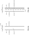
- FIGS. 2A-2B partial side views of panels with and without a resonator 204 according to an exemplary embodiment are shown.
- sidewalls 200, 202 defining an airgap function as a mass-spring-mass system 206; sound waves interact with the first sidewall 200 that vibrates and transmits the sound waves into the panel and across to the second sidewall 202.
- Both sidewalls act as vibrating masses that are coupled through the air space between them, that acts as a spring and is characterized by its stiffness.
- the resonator 204 changes the stiffness of the space between the sidewalls 200, 202 and thereby alters the characteristics of the mass-spring-mass system to absorb acoustic energy and reduce the noise transferred across the panel.
- the resonator 204 defines a geometry to tune the panel over certain target frequencies and / or a frequency range to minimize or reduce the transmission. Furthermore, sound waves may enter at oblique angles. The resonator 204 defines surfaces to produce reflections inside the panel that reflect until they finally transmit to the second sidewall 202.
- a resonator 300, 302 according to at least one embodiment comprises a plurality of regularly spaced cells 304, 306, 308.
- Each cell 304, 306, 308, or some subset of cells 304, 306, 308, defines an opening 310 (such as a hole of some appropriate shape) to allow air internal to the cell 304, 306, 308 to enter and leave the corresponding cell 304, 306, 308 in response to acoustic pressure waves.
- the cells 304, 306, 308 may comprise a substantially hemispherical geometry (as shown by a first cell 304), a conical geometry (as shown by a second cell 306), a faceted geometry (as shown by a third cell 308), or the like.
- Different cell shapes may define tunable features to allow the resonator 300, 302 to function efficiently in response certain desirable frequency ranges.
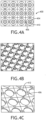
- the resonator 400 comprises a plurality of regularly spaced cells 404, some or all of the cells defining an opening 410 (hole) to allow air to enter and leave an internal space in response to acoustic pressure waves.
- cells 404 may be in fluid communication with neighboring cells 404 via a duct 406 formed in the sheet defining the cells 404.
- each cell 404 may define an opening 412 in the surface proximal to a sidewall where the resonator is disposed.
- the resonator 400 may be comprises of a single sheet formed into the plurality of cells 404. It may be further appreciated that the resonator 400 may be formed via thermoforming, additive manufacturing, or the like.
- the resonator cell 500 comprises a geometry defined by a height, a width (or diameter), an angle of the cell wall 502, and thickness of the cell wall 502.
- the features of the resonator cell 500 define a volume of air inside.
- the shape and characteristics of the resonator cell 500 define the features of a mass-spring damper.
- the resonator cell 500 may include one or more ducts 506 connecting the internal air volume of the resonator cell 500 to one or more resonator cells 500.
- Features of the resonator cell 500 include the size of the opening 510, define the dampening characteristics of the resonator cell 500 (or set of resonator cells 500 in fluid communication via one or more ducts 506). Such features may be determined at the time of manufacture according to a desired frequency or frequency range. In at least one embodiment, the features of the resonator cell 500 may be defined with respect certain features of the panel including the resonator cell 500. For example, a resonator cell 500 may have a height between 15% and 95% of the space between a first sidewall and a second sidewall (to produce a smaller or larger airgap).
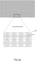
- resonator cells 600 may be organized into sets of resonator cells 600 with distinct openings 602, 604.
- a first set of resonator cells 600 may define openings 602 with a first diameter while a second set of resonator cells 600 defines openings 604 with a second diameter.
- Differing diameter openings 602, 604 may alter the acoustic dampening properties of the resonator cells 600 such that the different sets of resonator cells 600 are optimized for different frequencies, allowing the acoustic panel to reduce sound transmission over a broader frequency range.
- each resonator cells 606 may be connected to a neighboring resonator cell 606 via a duct 608.
- one of the connected resonator cells 606 may define an opening 610 while the other resonator cell 606 defines a closed top surface 612.
- the combined resonator cells 606 define a singular internal air volume, distributed across the two resonator cells 606.
- three or more resonator cells 614 may be similarly connected via ducts 616, 618 to neighboring resonator cells 614, where only one of the connected resonator cells 614 defines an opening 620.
- Multiple resonator cells 606, 614 connected via ducts 608, 616, 618 may create a system of resonator cells 606, 614 with multiple resonance frequencies, lower than the resonance frequency of any single resonator cell 606, 614.
- Interconnected resonator cells 606, 614 act like a mass-spring-mass-spring system and provide additional degrees of freedom and frequencies for turning. This configuration is particularly suited for addressing low frequency tones.
- a single resonator may include multiple type of resonator cell 600, 606, 614 configurations to tune the resonator based on desired operating frequencies.
- resonator cells 600, 606, 614 and ducts 608, 616, 618 may be formed in a regular, contiguous layer. Openings 602, 604, 610, 620 of various sizes may then be cut or stamped into a top surface of certain resonator cells 600, 606, 614. Likewise, certain ducts may be pinched off or otherwise sealed were not desirable. Alternatively, only those ducts 608, 616, 618 that are desired may be formed in a subsequent process.
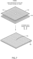
- the resonator 700 includes a plurality of resonator cells as described herein.
- a sheet layer 702 includes a plurality of openings 704, each corresponding to one of the resonator cells.
- the sheet layer 702 surrounds a top portion of each resonator cell and forms a substantially air tight surface.
- the sheet layer 702 defines an internal airspace, separate from the internal airspace defined by each resonator cell.
- one or more resonator cells may be removed from the resonator 700 so that the corresponding opening 704 in the membrane layer 702 is open to airgap defined by the first sidewall.
- Such opening 706 is conceptually similar the resonator cell openings described herein, for the air volume defined by the internal space between the membrane layer 702 and the resonator 700.
- Such embodiments may function for very low frequencies.
- Each panel includes a first sidewall 800, a second sidewall 802, and a resonator 804 disposed on the second sidewall as described herein.
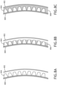
- the first sidewall 800 and resonator 804 define an airgap. In at least one embodiment (such as in FIG. 8A ), the airgap is unencumbered.
- the airgap may be partially filled with a bulk absorber 806.
- a bulk absorber 806 may comprise a foam, aerogel, or other material outside of the outside of the resonator 804.
- the entire airgap may be filled with a bulk absorber 808.
- Such bulk absorber 806, 808 may comprise a porous material that may include certain acoustic properties to absorb or dampen frequencies higher than those absorbed or dampened by the resonator 804. Such bulk absorbers 806, 808 may be more efficient at absorbing such frequencies than the resonator 804. In at least one embodiment, the bulk absorber 806, 808 may include certain thermal properties to act as a thermal insulator.
- first sidewall 800, second sidewall 802, and resonator 804 may be curved according to an exterior surface of a mobile platform. Furthermore, it may be appreciated that the first sidewall 800 may comprise the exterior surface of the mobile platform.
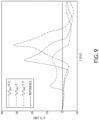
- FIG. 9 graphs of frequency response in resonator panels according to exemplary embodiments are shown.
- Panels according to the inventive concepts described herein may be tuned to be most operative with certain frequency ranges.
- resonators are tunable to produce transmission absorption at low frequencies that may generally correspond to known engine noise. Panels with such resonators may be less effective at absorbing higher frequencies, or even less effective than a panel without a resonator.
- a bulk absorber may enable a panel to absorb those higher frequencies, at least as well as existing panels, and with additional thermal insulating properties.
Landscapes
- Engineering & Computer Science (AREA)
- Mechanical Engineering (AREA)
- Aviation & Aerospace Engineering (AREA)
- Chemical & Material Sciences (AREA)
- Manufacturing & Machinery (AREA)
- Materials Engineering (AREA)
- Soundproofing, Sound Blocking, And Sound Damping (AREA)
Abstract
A vehicle panel includes two sidewalls (100, 102) and a resonator (104) disposed between them on one of the cell walls. The resonator includes a network of cells (304, 306, 308), each cell defines an internal space to absorb and dissipate noise and vibrations within a specific frequency range. Certain cells or subsets of cells may be interconnected to define a larger internal cell space. An airgap (106) between the resonator and one of the sidewalls may be partially or completely filled with dampening material to absorb high frequency noise. The dampening material may also provide thermal insulation.
Description
- The present application claims the benefit of
U.S. Provisional App. No. 63/444,008 (filed February 8, 2023 US application No. 18/416.094 filed on 18 January 2024 - Vehicle interiors suffer from noise transmission and a lack of thermal insulation. Such noise may be external (engine noise and the like) or internal (noise from passengers and galley or lavatory equipment). Noise impacts the comfort and health of personnel in commercial aircraft, business jets, military jets, helicopters, urban air-mobility concepts, submarines, aircraft carriers, etc. Modern turboprop engines cause low-frequency noise transmission into the cabin. In many instances there is insufficient paneling to reduce the noise level inside the cabin. Some applications require dual thermal and acoustic / vibration reduction. It would be advantageous to have multifunctional panel solution to reduce noise in a variety of applications, and provide thermal insulation.
- In one aspect, embodiments of the inventive concepts disclosed herein are directed to an aircraft panel with two sidewalls and a resonator disposed between them on one of the cell walls. The resonator includes a network of cells, each cell defines an internal space to absorb and dissipate noise and vibrations within a specific frequency range.
- In embodiments, certain cells or subsets of cells may be interconnected to define a larger internal cell space.
- In embodiments, an airgap between the resonator and one of the sidewalls may be partially or completely filled with dampening material to absorb high frequency noise. The dampening material may also provide thermal insulation.
- It is to be understood that both the foregoing general description and the following detailed description are exemplary and explanatory only and should not restrict the scope of the claims. The accompanying drawings, which are incorporated in and constitute a part of the specification, illustrate exemplary embodiments of the inventive concepts disclosed herein and together with the general description, serve to explain the principles.
- The numerous advantages of the embodiments of the inventive concepts disclosed herein may be better understood by those skilled in the art by reference to the accompanying figures in which:
-
FIG. 1 shows a partial side view of a panel according to an exemplary embodiment; -
FIG. 2A shows a partial side view of a panel; -
FIG. 2B shows a partial side view of a panel according to an exemplary embodiment; -
FIG. 3A shows a partial perspective view of a resonator according to an exemplary embodiment; -
FIG. 3B shows a partial perspective view of a resonator according to an exemplary embodiment; -
FIG. 3C shows perspective views of resonator cells according to exemplary embodiments; -
FIG. 4A shows a partial top view of a resonator according to an exemplary embodiment; -
FIG. 4B shows a partial perspective view of a resonator according to an exemplary embodiment; -
FIG. 4C shows a partial bottom view of a resonator according to an exemplary embodiment; -
FIG. 5A shows a perspective view of a resonator cell according to an exemplary embodiment; -
FIG. 5B shows a side cross-sectional view of a resonator cell according to an exemplary embodiment; -
FIG. 6A shows a top view of resonator cells according to an exemplary embodiment; -
FIG. 6B shows a top view of resonator cells according to an exemplary embodiment; -
FIG. 6C shows a top view of resonator cells according to an exemplary embodiment; -
FIG. 7 shows a perspective view of a resonator according to an exemplary embodiment; -
FIG. 8A shows a partial side view of a panel according to an exemplary embodiment; -
FIG. 8B shows a partial side view of a panel according to an exemplary embodiment; -
FIG. 8C shows a partial side view of a panel according to an exemplary embodiment; -
FIG. 9 shows graphs of frequency response in resonator panels according to exemplary embodiments; - Before explaining various embodiments of the inventive concepts disclosed herein in detail, it is to be understood that the inventive concepts are not limited in their application to the arrangement of the components or steps or methodologies set forth in the following description or illustrated in the drawings. In the following detailed description of embodiments of the instant inventive concepts, numerous specific details are set forth in order to provide a more thorough understanding of the inventive concepts. However, it will be apparent to one of ordinary skill in the art having the benefit of the instant disclosure that the inventive concepts disclosed herein may be practiced without these specific details. In other instances, well-known features may not be described in detail to avoid unnecessarily complicating the instant disclosure. The inventive concepts disclosed herein are capable of other embodiments or of being practiced or carried out in various ways provided they fall within the scope of the claims. Also, it is to be understood that the phraseology and terminology employed herein is for the purpose of description and should not be regarded as limiting.
- As used herein a letter following a reference numeral is intended to reference an embodiment of a feature or element that may be similar, but not necessarily identical, to a previously described element or feature bearing the same reference numeral (e.g., 1, 1a, 1b). Such shorthand notations are used for purposes of convenience only and should not be construed to limit the inventive concepts disclosed herein in any way unless expressly stated to the contrary.
- Further, unless expressly stated to the contrary, "or" refers to an inclusive or and not to an exclusive or. For example, a condition A or B is satisfied by anyone of the following: A is true (or present) and B is false (or not present), A is false (or not present) and B is true (or present), and both A and B are true (or present).
- In addition, use of "a" or "an" are employed to describe elements and components of embodiments of the instant inventive concepts. This is done merely for convenience and to give a general sense of the inventive concepts, and "a" and "an" are intended to include one or at least one and the singular also includes the plural unless it is obvious that it is meant otherwise.
- Also, while various components may be depicted as being connected directly, direct connection is not a requirement. Components may be in data communication with intervening components that are not illustrated or described.
- Finally, as used herein any reference to "one embodiment," or "some embodiments" means that a particular element, feature, structure, or characteristic described in connection with the embodiment is included in at least one embodiment of the inventive concepts disclosed herein. The appearances of the phrase "in at least one embodiment" in the specification does not necessarily refer to the same embodiment. Embodiments of the inventive concepts disclosed may include one or more of the features expressly described or inherently present herein, or any combination or sub-combination of two or more such features.
- Broadly, embodiments of the inventive concepts disclosed herein are directed to an aircraft panel with two sidewalls and a resonator disposed between them on one of the cell walls. The resonator includes a network of cells, each cell defines an internal space to absorb and dissipate noise and vibrations within a specific frequency range. Certain cells or subsets of cells may be interconnected to define a larger internal cell space. An airgap between the resonator and one of the sidewalls may be partially or completely filled with dampening material to absorb high frequency noise. The dampening material may also provide thermal insulation.
- Referring to
FIG. 1 , a partial side view of a panel according to an exemplary embodiment is shown. In at least one embodiment, the panel includes afirst sidewall 100 disposed externally, or proximal to an external surface, to a mobile platform. Thefirst sidewall 100 receivesexternal noise 108 that may be within certain known frequency ranges. Suchexternal noise 108 induces vibrations in thefirst sidewall 100 which are transmitted to anairgap 106 defined by thefirst sidewall 100 and aresonator 104 disposed on asecond sidewall 102. - The
double sidewall resonator 104 core, andairgap 106 dampen theexternal noise 108 via acoustic reflection and energy absorption within theresonator 104, and transmit reducednoise 110 into the interior of the mobile platform. In at least one embodiment, thefirst sidewall 100 may comprise an external surface of a mobile platform and thesecond sidewall 102 may define a cabin surface. - In at least one embodiment, the
resonator 104 may be a thermal formed material such as a thermoplastic. It may be appreciated that within certain mobile platforms, there are material constraints based on flammability and toxicity. Embodiments of the present disclosure are directed to certain geometries of theresonator 104 rather than specific materials as more fully described herein. - Referring to
FIGS. 2A-2B , partial side views of panels with and without aresonator 204 according to an exemplary embodiment are shown. Traditionally, sidewalls 200, 202 defining an airgap function as a mass-spring-mass system 206; sound waves interact with thefirst sidewall 200 that vibrates and transmits the sound waves into the panel and across to thesecond sidewall 202. Both sidewalls act as vibrating masses that are coupled through the air space between them, that acts as a spring and is characterized by its stiffness. In at least one embodiment, theresonator 204 changes the stiffness of the space between thesidewalls - In at least one embodiment, the
resonator 204 defines a geometry to tune the panel over certain target frequencies and / or a frequency range to minimize or reduce the transmission. Furthermore, sound waves may enter at oblique angles. Theresonator 204 defines surfaces to produce reflections inside the panel that reflect until they finally transmit to thesecond sidewall 202. - Referring to
FIGS. 3A-3C , partial perspective views ofresonators resonator cells resonator cells cell cells cell corresponding cell - In at least one embodiment, the
cells resonator - Referring to
FIGS. 4A-4C , partial top, perspective, and bottom views of aresonator 400 according to an exemplary embodiment are shown. Theresonator 400 comprises a plurality of regularly spacedcells 404, some or all of the cells defining an opening 410 (hole) to allow air to enter and leave an internal space in response to acoustic pressure waves. In at least one embodiment,cells 404 may be in fluid communication with neighboringcells 404 via aduct 406 formed in the sheet defining thecells 404. - In at least one embodiment, each
cell 404 may define anopening 412 in the surface proximal to a sidewall where the resonator is disposed. It may be appreciated theresonator 400 may be comprises of a single sheet formed into the plurality ofcells 404. It may be further appreciated that theresonator 400 may be formed via thermoforming, additive manufacturing, or the like. - Referring to
FIGS. 5A-5B , perspective and side, cross-sectional views of aresonator cell 500 according to an exemplary embodiment are shown. Theresonator cell 500 comprises a geometry defined by a height, a width (or diameter), an angle of thecell wall 502, and thickness of thecell wall 502. The features of theresonator cell 500 define a volume of air inside. Anopening 510 in thecell wall 502, which may be disposed in a top surface of theresonator cell 500, allows air to move in and out of the volume. The shape and characteristics of theresonator cell 500 define the features of a mass-spring damper. Acoustic waves induce the motion of a slug of air inside the hole 510 (mass effect), which in turn compresses the air inside the volume that is enclosed by the walls 502 (spring force). Acoustic absorption (damping effect) takes place in thehole 510 through friction losses from the air movement and in the flow itself. - In at least one embodiment, the
resonator cell 500 may include one or more ducts 506 connecting the internal air volume of theresonator cell 500 to one ormore resonator cells 500. - Features of the
resonator cell 500, include the size of theopening 510, define the dampening characteristics of the resonator cell 500 (or set ofresonator cells 500 in fluid communication via one or more ducts 506). Such features may be determined at the time of manufacture according to a desired frequency or frequency range. In at least one embodiment, the features of theresonator cell 500 may be defined with respect certain features of the panel including theresonator cell 500. For example, aresonator cell 500 may have a height between 15% and 95% of the space between a first sidewall and a second sidewall (to produce a smaller or larger airgap). - Referring to
FIGS. 6A-6C , top views ofresonator cells resonator cells 600 may be organized into sets ofresonator cells 600 withdistinct openings 602, 604. For example, a first set ofresonator cells 600 may defineopenings 602 with a first diameter while a second set ofresonator cells 600 defines openings 604 with a second diameter. Differingdiameter openings 602, 604 may alter the acoustic dampening properties of theresonator cells 600 such that the different sets ofresonator cells 600 are optimized for different frequencies, allowing the acoustic panel to reduce sound transmission over a broader frequency range. - In at least one embodiment, each
resonator cells 606 may be connected to a neighboringresonator cell 606 via aduct 608. In such embodiments, one of the connectedresonator cells 606 may define anopening 610 while theother resonator cell 606 defines a closed top surface 612. The combinedresonator cells 606 define a singular internal air volume, distributed across the tworesonator cells 606. Likewise, three ormore resonator cells 614 may be similarly connected viaducts resonator cells 614, where only one of the connectedresonator cells 614 defines anopening 620.Multiple resonator cells ducts resonator cells single resonator cell Interconnected resonator cells - It may be appreciated that a single resonator may include multiple type of
resonator cell resonator cells ducts Openings certain resonator cells ducts - Referring to
FIG. 7 , a perspective view of aresonator 700 according to an exemplary embodiment is shown. In at least one embodiment, theresonator 700 includes a plurality of resonator cells as described herein. Asheet layer 702 includes a plurality ofopenings 704, each corresponding to one of the resonator cells. Thesheet layer 702 surrounds a top portion of each resonator cell and forms a substantially air tight surface. Thesheet layer 702 defines an internal airspace, separate from the internal airspace defined by each resonator cell. - In at least one embodiment, one or more resonator cells may be removed from the
resonator 700 so that thecorresponding opening 704 in themembrane layer 702 is open to airgap defined by the first sidewall.Such opening 706 is conceptually similar the resonator cell openings described herein, for the air volume defined by the internal space between themembrane layer 702 and theresonator 700. Such embodiments may function for very low frequencies. - Referring to
FIGS. 8A-8C , partial side views of panels according to exemplary embodiments are shown. Each panel includes afirst sidewall 800, asecond sidewall 802, and aresonator 804 disposed on the second sidewall as described herein. Thefirst sidewall 800 andresonator 804 define an airgap. In at least one embodiment (such as inFIG. 8A ), the airgap is unencumbered. - In at least one embodiment (as in
FIG. 8B ), the airgap may be partially filled with abulk absorber 806.Such bulk absorber 806 may comprise a foam, aerogel, or other material outside of the outside of theresonator 804. Furthermore, in at least one embodiment (such as inFIG. 8C ), the entire airgap may be filled with abulk absorber 808. -
Such bulk absorber resonator 804.Such bulk absorbers resonator 804. In at least one embodiment, thebulk absorber - In at least one embodiment, the
first sidewall 800,second sidewall 802, andresonator 804 may be curved according to an exterior surface of a mobile platform. Furthermore, it may be appreciated that thefirst sidewall 800 may comprise the exterior surface of the mobile platform. - Referring to
FIG. 9 , graphs of frequency response in resonator panels according to exemplary embodiments are shown. Panels according to the inventive concepts described herein may be tuned to be most operative with certain frequency ranges. In at least one embodiment, resonators are tunable to produce transmission absorption at low frequencies that may generally correspond to known engine noise. Panels with such resonators may be less effective at absorbing higher frequencies, or even less effective than a panel without a resonator. In such embodiments, a bulk absorber may enable a panel to absorb those higher frequencies, at least as well as existing panels, and with additional thermal insulating properties. - It is believed that the inventive concepts disclosed herein and many of their attendant advantages will be understood by the foregoing description of embodiments of the inventive concepts, and it will be apparent that various changes may be made in the form, construction, and arrangement of the components thereof without departing from the scope of the invention as defined by the claims.
Claims (14)
- A panel resonator (104) comprising:a plurality of regularly spaced cells (304, 306, 308), each cell defining an internal space, the plurality of regularly spaced cells configured to at least partially define an airgap (106) between a first sidewall (100) of a panel and the resonator,wherein the regularly spaced cells are configured to be disposed on an internal surface of a second sidewall (102) of the panel.
- The panel resonator of Claim 1, wherein at least one of the regularly spaced cells defines an opening (310) to allow air movement from the internal space.
- The panel resonator of Claim 2, wherein:the opening comprises a hole having a first diameter;at least one of the regularly spaced cells defines a hole having a second diameter different from the first diameter; andthe first diameter and the second diameter are tuned for specific, different frequency ranges.
- The panel resonator of any preceding Claim, wherein at least two of the regularly spaced cells are in fluid communication with each other.
- The panel resonator of Claim 4, wherein one of the at least two regularly spaced cells defines an opening to allow air movement from the internal space.
- The panel resonator of any preceding Claim, further comprising a membrane layer (702) configured to surround top portion of each of the regularly spaced cells to define a second internal space.
- An aircraft panel comprising:a first sidewall (100);a second sidewall (102); anda resonator (104) as claimed in any preceding claim disposed between the first sidewall and second sidewall,wherein:
the resonator is disposed on the second sidewall to at least partially define the airgap between the first sidewall and the resonator. - The aircraft panel of Claim 7, further comprising a filler material at least partially filling the airgap.
- The aircraft panel of Claim 8, wherein the filler material is configured to a frequency range of vibrations.
- The aircraft panel of Claim 8 or 9, wherein the filler material is configured as a thermal insulator.
- A mobile platform comprising:
a plurality of panels, each comprising:a first sidewall (100);a second sidewall (102); anda resonator (104) as claimed in any of claims 1 to 6, disposed between the first sidewall and second sidewall,wherein:
the resonator is disposed on the second sidewall to at least partially define the airgap between the first sidewall and the resonator. - The mobile platform of Claim 11, further comprising a filler material at least partially filling the airgap, configured to a frequency range of vibrations.
- The mobile platform of Claim 12, wherein the filler material is configured as a thermal insulator.
- The mobile platform of Claim 11, 12 or 13, wherein the first sidewall, second sidewall, and resonator are curved to conform to a portion of the mobile platform.
Applications Claiming Priority (2)
| Application Number | Priority Date | Filing Date | Title |
|---|---|---|---|
| US202363444008P | 2023-02-08 | 2023-02-08 | |
| US18/416,094 US12623769B2 (en) | 2023-02-08 | 2024-01-18 | Transmission loss panel for aircraft cabin noise and thermal treatment |
Publications (1)
| Publication Number | Publication Date |
|---|---|
| EP4414164A1 true EP4414164A1 (en) | 2024-08-14 |
Family
ID=89898091
Family Applications (1)
| Application Number | Title | Priority Date | Filing Date |
|---|---|---|---|
| EP24156636.3A Pending EP4414164A1 (en) | 2023-02-08 | 2024-02-08 | Transmission loss panel for aircraft cabin noise and thermal treatment |
Country Status (2)
| Country | Link |
|---|---|
| US (1) | US12623769B2 (en) |
| EP (1) | EP4414164A1 (en) |
Citations (3)
| Publication number | Priority date | Publication date | Assignee | Title |
|---|---|---|---|---|
| WO2015023389A1 (en) * | 2013-08-12 | 2015-02-19 | Hexcel Corporation | Sound wave guide for use in acoustic structures |
| US20190063318A1 (en) * | 2017-08-29 | 2019-02-28 | Mra Systems, Llc. | Acoustic liner having internal structure |
| US20190272812A1 (en) * | 2017-02-01 | 2019-09-05 | General Electric Company | Continuous degree of freedom acoustic cores |
Family Cites Families (67)
| Publication number | Priority date | Publication date | Assignee | Title |
|---|---|---|---|---|
| US2000806A (en) * | 1932-05-18 | 1935-05-07 | Macoustic Engineering Company | Method of and apparatus for sound modification |
| US2159488A (en) * | 1935-08-01 | 1939-05-23 | Johns Manville | Perforated membrane |
| US2840179A (en) | 1954-06-17 | 1958-06-24 | Miguel C Junger | Sound-absorbing panels |
| US2887173A (en) * | 1957-05-22 | 1959-05-19 | G A Societa Per Azioni Sa | Sound absorbing and insulating panel |
| US3597891A (en) * | 1969-10-02 | 1971-08-10 | Mc Donnell Douglas Corp | Interior absorptive panel |
| US3834487A (en) * | 1973-03-08 | 1974-09-10 | J Hale | Sandwich core panel with structural decoupling between the outer face sheets thereof |
| US3851724A (en) * | 1974-02-25 | 1974-12-03 | Bomco | Acoustic damping structures |
| DE2506472A1 (en) | 1975-02-07 | 1976-08-19 | Lockheed Aircraft Corp | Sound absorbing panel effective in two frequency domains - combines action of Helm holtz resonator with that of laminar honeycomb absorber |
| GB2038410B (en) * | 1978-12-27 | 1982-11-17 | Rolls Royce | Acoustic lining utilising resonance |
| US4291080A (en) | 1980-03-31 | 1981-09-22 | Vought Corporation | Sound attenuating structural panel |
| US4421201A (en) | 1981-09-29 | 1983-12-20 | The Boeing Company | High efficiency broadband acoustic resonator and absorption panel |
| US4600078A (en) * | 1983-12-12 | 1986-07-15 | Lockheed Corporation | Sound barrier |
| JPS61249853A (en) * | 1985-04-30 | 1986-11-07 | Mazda Motor Corp | Sound absorbing structure for vehicle |
| DE3733285C2 (en) * | 1987-10-02 | 1994-02-10 | Helmut Pelzer | Cladding of sound absorbing components and device for their production |
| US5185504A (en) * | 1992-06-30 | 1993-02-09 | Jen Wang H | Acoustic board |
| US5004070A (en) * | 1990-08-16 | 1991-04-02 | Wang Hong Jen | Acoustic board |
| FR2700179B1 (en) * | 1993-01-07 | 1995-06-09 | Bouygues Sa | SOUND INSULATION WALL AND ITS APPLICATIONS AS A FLOOR TILE OR A WALL. |
| DE19804567C2 (en) * | 1998-02-05 | 2003-12-11 | Woco Franz Josef Wolf & Co Gmbh | Surface absorber for sound waves and use |
| US6158690A (en) | 1998-10-30 | 2000-12-12 | Sikorsky Aircraft Corporation | Cabin interior panel system for reducing noise transmission in an aircraft |
| JP2001003482A (en) * | 1999-06-25 | 2001-01-09 | Fujita Corp | Hollow double sound insulation wall structure |
| FR2815900B1 (en) | 2000-10-31 | 2003-07-18 | Eads Airbus Sa | NOISE REDUCING SANDWICH PANEL, ESPECIALLY FOR AN AIRCRAFT TURBOREACTOR |
| CN1846251A (en) * | 2003-09-05 | 2006-10-11 | 株式会社神户制钢所 | Sound absorbing structure and method of producing the same |
| JP4453319B2 (en) * | 2003-09-25 | 2010-04-21 | トヨタ自動車株式会社 | Sound absorbing structure |
| KR20070004908A (en) * | 2004-04-30 | 2007-01-09 | 가부시키가이샤 고베 세이코쇼 | Porous sound absorbing structure |
| US7337875B2 (en) * | 2004-06-28 | 2008-03-04 | United Technologies Corporation | High admittance acoustic liner |
| US7510052B2 (en) | 2005-04-04 | 2009-03-31 | Hexcel Corporation | Acoustic septum cap honeycomb |
| KR100894597B1 (en) * | 2007-04-09 | 2009-04-24 | 백해숙 | Styrofoam panel for preventing noise between floors and its sound insulation and sound absorption structure |
| FR2929746B1 (en) | 2008-04-07 | 2010-09-03 | Hutchinson | ACOUSTIC INSULATION PANEL |
| US8464831B2 (en) * | 2009-09-17 | 2013-06-18 | Volvo Aero Corporation | Noise attenuation panel and a gas turbine component comprising a noise attenuation panel |
| FR2959056B1 (en) | 2010-04-16 | 2015-05-29 | Hutchinson | ACOUSTIC INSULATION DEVICE AND METHOD FOR MANUFACTURING THE SAME |
| EP2595142B1 (en) * | 2010-07-15 | 2021-01-20 | Aishin Kako Kabushiki Kaisha | Sound absorption characteristic structure |
| ITTO20111124A1 (en) | 2011-12-09 | 2013-06-10 | Alenia Aermacchi Spa | ELEMENT FOR SOUND ABSORPTION, IN PARTICULAR INTENDED TO BE MOUNTED ON AIRCRAFT COMPONENTS, SUCH AS GONDOLAS ENGINES. |
| US8657067B1 (en) * | 2012-09-25 | 2014-02-25 | The Boeing Company | Acoustic damping device for noise reduction |
| US8869933B1 (en) | 2013-07-29 | 2014-10-28 | The Boeing Company | Acoustic barrier support structure |
| US8857563B1 (en) | 2013-07-29 | 2014-10-14 | The Boeing Company | Hybrid acoustic barrier and absorber |
| FR3012653B1 (en) | 2013-10-31 | 2017-03-03 | Eurocopter France | ACOUSTICALLY INSULATING COATING WITH RESONATORS, A PANEL PROVIDED WITH THIS COATING, AND AN AIRCRAFT |
| JP6043407B2 (en) * | 2015-02-27 | 2016-12-14 | 富士フイルム株式会社 | Soundproof structure and method for manufacturing soundproof structure |
| CN107531321B (en) | 2015-04-29 | 2020-08-07 | 庞巴迪公司 | Sound-damping device for an aircraft |
| CN204645298U (en) * | 2015-05-25 | 2015-09-16 | 常州国源包装有限公司 | Adopt sound wallboard |
| CN107514066B (en) * | 2016-06-16 | 2019-05-17 | 中国科学院声学研究所 | A lightweight low-frequency sound insulation device based on extension tube resonance structure |
| FR3054608B1 (en) | 2016-07-29 | 2020-06-26 | Safran | ACOUSTIC PANEL FOR A TURBOMACHINE AND ITS MANUFACTURING METHOD |
| CN109641416A (en) | 2016-08-19 | 2019-04-16 | 3M创新有限公司 | Abatvoix including the core being made of the unit connected, it is wherein some with opening in cell-wall |
| FR3065570B1 (en) | 2017-04-21 | 2019-05-03 | Office National D'etudes Et De Recherches Aerospatiales | SURFACIAL TRIM FOR ACOUSTIC ABSORPTION |
| KR101973022B1 (en) * | 2017-09-13 | 2019-04-26 | 한국기계연구원 | Sound absorbing cell and sound absorbing structure having the same |
| US10726824B2 (en) | 2017-09-29 | 2020-07-28 | The Boeing Company | Composite sound absorption panel assembly |
| US11315538B2 (en) | 2017-12-13 | 2022-04-26 | The Boeing Company | Anti-resonant panels |
| KR102116466B1 (en) * | 2018-09-12 | 2020-05-28 | 한국과학기술원 | Sound absorbing apparatus |
| FR3081510B1 (en) | 2018-05-24 | 2020-05-29 | Safran Nacelles | ACOUSTIC MITIGATION PANEL FOR AIRCRAFT TURBOREACTOR NACELLE |
| WO2020050358A1 (en) | 2018-09-06 | 2020-03-12 | 三菱ケミカル株式会社 | Sound-blocking sheet member, sound-blocking structure using same, and method for manufacturing sound-blocking sheet member |
| FR3085783B1 (en) | 2018-09-10 | 2021-04-23 | Safran Aircraft Engines | ACOUSTIC TREATMENT PANEL FOR TURBOREACTOR |
| CN109533269A (en) | 2018-11-26 | 2019-03-29 | 中国人民解放军国防科技大学 | Low-frequency vibration-damping noise-reducing sound-insulating wall plate structure for aircraft cabin |
| IT201900004761A1 (en) | 2019-03-29 | 2020-09-29 | Leonardo Spa | Manufacturing process of a sound-absorbing panel with a sandwich structure to reduce the sound impact of an aircraft engine |
| FR3098143A1 (en) * | 2019-07-05 | 2021-01-08 | Airbus Operations | Sound-absorbing coating comprising a honeycomb structure formed of longitudinal bands forming Helmholtz resonators and intermediate cavities treating different acoustic ranges |
| US11437008B2 (en) | 2019-11-12 | 2022-09-06 | Hexcel Corporation | Acoustic barrier caps in acoustic honeycomb |
| KR102501146B1 (en) * | 2020-09-21 | 2023-02-17 | 한국과학기술원 | Sound absorbing apparatus |
| CN214986013U (en) | 2020-12-29 | 2021-12-03 | 中国航空工业集团公司西安飞机设计研究所 | Aircraft wallboard structure for noise reduction |
| US12104536B2 (en) | 2021-05-12 | 2024-10-01 | Rohr, Inc. | Nacelle liner comprising unit cell resonator networks |
| IT202100017474A1 (en) | 2021-07-02 | 2023-01-02 | Leonardo Spa | Manufacturing process of a sound-absorbing panel core with sandwich structure for noise reduction in an aircraft |
| US12269245B2 (en) | 2021-09-20 | 2025-04-08 | Airbus Operations Sas | Acoustic treatment panel comprising acoustic cells of different volumes obtained from cylindrical and identical main tubes, aircraft comprising such an acoustic treatment panel |
| US11781485B2 (en) | 2021-11-24 | 2023-10-10 | Rtx Corporation | Unit cell resonator networks for gas turbine combustor tone damping |
| US11994036B2 (en) | 2022-01-26 | 2024-05-28 | Rohr, Inc. | Unit cell resonator networks for acoustic and vibration damping |
| US12071217B2 (en) | 2022-03-10 | 2024-08-27 | Rohr, Inc. | Additive manufacturing of unit cell resonator networks for acoustic damping |
| US20230349151A1 (en) * | 2022-04-28 | 2023-11-02 | Toyota Motor Engineering & Manufacturing North America, Inc. | Sound absorber and sound absorbing device |
| EP4279261A1 (en) | 2022-05-16 | 2023-11-22 | Airbus Operations SAS | Acoustic panel for aircraft having a wide band of noise attenuation frequency combining two resonators and method for manufacturing the acoustic panel |
| CN217994767U (en) | 2022-09-21 | 2022-12-09 | 盐城工学院 | An interior panel structure for noise reduction in aircraft cabins |
| US20240262066A1 (en) * | 2023-02-08 | 2024-08-08 | B/E Aerospace, Inc. | Continuous manufacturing method of acoustic transmission loss panels with resonator network cores |
| CN117809611A (en) * | 2023-12-29 | 2024-04-02 | 浙江零跑科技股份有限公司 | Acoustic structures and array devices |
-
2024
- 2024-01-18 US US18/416,094 patent/US12623769B2/en active Active
- 2024-02-08 EP EP24156636.3A patent/EP4414164A1/en active Pending
Patent Citations (3)
| Publication number | Priority date | Publication date | Assignee | Title |
|---|---|---|---|---|
| WO2015023389A1 (en) * | 2013-08-12 | 2015-02-19 | Hexcel Corporation | Sound wave guide for use in acoustic structures |
| US20190272812A1 (en) * | 2017-02-01 | 2019-09-05 | General Electric Company | Continuous degree of freedom acoustic cores |
| US20190063318A1 (en) * | 2017-08-29 | 2019-02-28 | Mra Systems, Llc. | Acoustic liner having internal structure |
Also Published As
| Publication number | Publication date |
|---|---|
| US12623769B2 (en) | 2026-05-12 |
| US20240262488A1 (en) | 2024-08-08 |
Similar Documents
| Publication | Publication Date | Title |
|---|---|---|
| US9270253B2 (en) | Hybrid acoustic barrier and absorber | |
| US6186270B1 (en) | Layered sound absorber for absorbing acoustic sound waves | |
| US6935472B2 (en) | Damping structure and applications | |
| US9378721B2 (en) | Low frequency acoustic attenuator and process for making same | |
| US20090223738A1 (en) | Sound absorbing structure and vehicle component having sound absorption property | |
| JPS61500692A (en) | acoustic barrier | |
| JPH0247614B2 (en) | ||
| EP2175441A2 (en) | Sound absorbing structure built into luggage compartement of vehicle | |
| AU2018306554A1 (en) | Shroud | |
| CN111354330A (en) | Broadband sparse sound absorber | |
| EP3670329B1 (en) | Two-way acoustic panel | |
| US6082489A (en) | Sound isolation plate structure | |
| US5904318A (en) | Passive reduction of aircraft fuselage noise | |
| US12623769B2 (en) | Transmission loss panel for aircraft cabin noise and thermal treatment | |
| US20220366888A1 (en) | Acoustic panel for noise attenuation | |
| JP2018115577A (en) | Suppression member | |
| WO2018189879A1 (en) | Railway vehicle | |
| CN117809611A (en) | Acoustic structures and array devices | |
| JP6496769B2 (en) | Sound absorption panel | |
| CN111688599A (en) | Sound insulation structure | |
| JP7385338B2 (en) | Automotive sound insulation panel | |
| US10399662B2 (en) | Aircraft with cabin acoustic systems having quarter wavelength absorbers | |
| JPS60172744A (en) | Vibrationproof device containing fluid | |
| KR101950694B1 (en) | Sound insulation panel of railway car body walls for reducing the interior noise | |
| JPS60164031A (en) | Vibration damper containing liquid therein |
Legal Events
| Date | Code | Title | Description |
|---|---|---|---|
| PUAI | Public reference made under article 153(3) epc to a published international application that has entered the european phase |
Free format text: ORIGINAL CODE: 0009012 |
|
| STAA | Information on the status of an ep patent application or granted ep patent |
Free format text: STATUS: THE APPLICATION HAS BEEN PUBLISHED |
|
| AK | Designated contracting states |
Kind code of ref document: A1 Designated state(s): AL AT BE BG CH CY CZ DE DK EE ES FI FR GB GR HR HU IE IS IT LI LT LU LV MC ME MK MT NL NO PL PT RO RS SE SI SK SM TR |
|
| STAA | Information on the status of an ep patent application or granted ep patent |
Free format text: STATUS: REQUEST FOR EXAMINATION WAS MADE |
|
| 17P | Request for examination filed |
Effective date: 20250213 |