EP4414144A2 - Systems and methods for controlling a surgical instrument - Google Patents
Systems and methods for controlling a surgical instrument Download PDFInfo
- Publication number
- EP4414144A2 EP4414144A2 EP24185548.5A EP24185548A EP4414144A2 EP 4414144 A2 EP4414144 A2 EP 4414144A2 EP 24185548 A EP24185548 A EP 24185548A EP 4414144 A2 EP4414144 A2 EP 4414144A2
- Authority
- EP
- European Patent Office
- Prior art keywords
- instrument
- control
- movement
- tissue
- manipulator
- Prior art date
- Legal status (The legal status is an assumption and is not a legal conclusion. Google has not performed a legal analysis and makes no representation as to the accuracy of the status listed.)
- Pending
Links
Images









Classifications
-
- A—HUMAN NECESSITIES
- A61—MEDICAL OR VETERINARY SCIENCE; HYGIENE
- A61B—DIAGNOSIS; SURGERY; IDENTIFICATION
- A61B17/00—Surgical instruments, devices or methods
- A61B17/00234—Surgical instruments, devices or methods for minimally invasive surgery
-
- A—HUMAN NECESSITIES
- A61—MEDICAL OR VETERINARY SCIENCE; HYGIENE
- A61B—DIAGNOSIS; SURGERY; IDENTIFICATION
- A61B17/00—Surgical instruments, devices or methods
- A61B17/32—Surgical cutting instruments
-
- A—HUMAN NECESSITIES
- A61—MEDICAL OR VETERINARY SCIENCE; HYGIENE
- A61B—DIAGNOSIS; SURGERY; IDENTIFICATION
- A61B17/00—Surgical instruments, devices or methods
- A61B17/42—Gynaecological or obstetrical instruments or methods
-
- A—HUMAN NECESSITIES
- A61—MEDICAL OR VETERINARY SCIENCE; HYGIENE
- A61B—DIAGNOSIS; SURGERY; IDENTIFICATION
- A61B34/00—Computer-aided surgery; Manipulators or robots specially adapted for use in surgery
-
- A—HUMAN NECESSITIES
- A61—MEDICAL OR VETERINARY SCIENCE; HYGIENE
- A61B—DIAGNOSIS; SURGERY; IDENTIFICATION
- A61B34/00—Computer-aided surgery; Manipulators or robots specially adapted for use in surgery
- A61B34/30—Surgical robots
-
- A—HUMAN NECESSITIES
- A61—MEDICAL OR VETERINARY SCIENCE; HYGIENE
- A61B—DIAGNOSIS; SURGERY; IDENTIFICATION
- A61B34/00—Computer-aided surgery; Manipulators or robots specially adapted for use in surgery
- A61B34/30—Surgical robots
- A61B34/35—Surgical robots for telesurgery
-
- A—HUMAN NECESSITIES
- A61—MEDICAL OR VETERINARY SCIENCE; HYGIENE
- A61B—DIAGNOSIS; SURGERY; IDENTIFICATION
- A61B34/00—Computer-aided surgery; Manipulators or robots specially adapted for use in surgery
- A61B34/30—Surgical robots
- A61B34/37—Leader-follower robots
-
- A—HUMAN NECESSITIES
- A61—MEDICAL OR VETERINARY SCIENCE; HYGIENE
- A61B—DIAGNOSIS; SURGERY; IDENTIFICATION
- A61B34/00—Computer-aided surgery; Manipulators or robots specially adapted for use in surgery
- A61B34/70—Manipulators specially adapted for use in surgery
-
- A—HUMAN NECESSITIES
- A61—MEDICAL OR VETERINARY SCIENCE; HYGIENE
- A61B—DIAGNOSIS; SURGERY; IDENTIFICATION
- A61B90/00—Instruments, implements or accessories specially adapted for surgery or diagnosis and not covered by any of the groups A61B1/00 - A61B50/00, e.g. for luxation treatment or for protecting wound edges
-
- B—PERFORMING OPERATIONS; TRANSPORTING
- B25—HAND TOOLS; PORTABLE POWER-DRIVEN TOOLS; MANIPULATORS
- B25J—MANIPULATORS; CHAMBERS PROVIDED WITH MANIPULATION DEVICES
- B25J3/00—Manipulators of leader-follower type, i.e. both controlling unit and controlled unit perform corresponding spatial movements
- B25J3/04—Manipulators of leader-follower type, i.e. both controlling unit and controlled unit perform corresponding spatial movements involving servo mechanisms
-
- B—PERFORMING OPERATIONS; TRANSPORTING
- B25—HAND TOOLS; PORTABLE POWER-DRIVEN TOOLS; MANIPULATORS
- B25J—MANIPULATORS; CHAMBERS PROVIDED WITH MANIPULATION DEVICES
- B25J9/00—Program-controlled manipulators
- B25J9/16—Program controls
- B25J9/1679—Program controls characterised by the tasks executed
- B25J9/1689—Teleoperation
-
- B—PERFORMING OPERATIONS; TRANSPORTING
- B25—HAND TOOLS; PORTABLE POWER-DRIVEN TOOLS; MANIPULATORS
- B25J—MANIPULATORS; CHAMBERS PROVIDED WITH MANIPULATION DEVICES
- B25J9/00—Program-controlled manipulators
- B25J9/16—Program controls
- B25J9/1694—Program controls characterised by use of sensors other than normal servo-feedback from position, speed or acceleration sensors, perception control, multi-sensor controlled systems, sensor fusion
- B25J9/1697—Vision controlled systems
-
- A—HUMAN NECESSITIES
- A61—MEDICAL OR VETERINARY SCIENCE; HYGIENE
- A61B—DIAGNOSIS; SURGERY; IDENTIFICATION
- A61B1/00—Instruments for performing medical examinations of the interior of cavities or tubes of the body by visual or photographical inspection, e.g. endoscopes; Illuminating arrangements therefor
- A61B1/313—Instruments for performing medical examinations of the interior of cavities or tubes of the body by visual or photographical inspection, e.g. endoscopes; Illuminating arrangements therefor for introducing through surgical openings, e.g. laparoscopes
- A61B1/3132—Instruments for performing medical examinations of the interior of cavities or tubes of the body by visual or photographical inspection, e.g. endoscopes; Illuminating arrangements therefor for introducing through surgical openings, e.g. laparoscopes for laparoscopy
-
- A—HUMAN NECESSITIES
- A61—MEDICAL OR VETERINARY SCIENCE; HYGIENE
- A61B—DIAGNOSIS; SURGERY; IDENTIFICATION
- A61B17/00—Surgical instruments, devices or methods
- A61B17/42—Gynaecological or obstetrical instruments or methods
- A61B17/4241—Instruments for manoeuvring or retracting the uterus, e.g. during laparoscopic surgery
-
- A—HUMAN NECESSITIES
- A61—MEDICAL OR VETERINARY SCIENCE; HYGIENE
- A61B—DIAGNOSIS; SURGERY; IDENTIFICATION
- A61B17/00—Surgical instruments, devices or methods
- A61B17/00234—Surgical instruments, devices or methods for minimally invasive surgery
- A61B2017/00292—Surgical instruments, devices or methods for minimally invasive surgery mounted on or guided by flexible, e.g. catheter-like, means
- A61B2017/00296—Surgical instruments, devices or methods for minimally invasive surgery mounted on or guided by flexible, e.g. catheter-like, means mounted on an endoscope
-
- A—HUMAN NECESSITIES
- A61—MEDICAL OR VETERINARY SCIENCE; HYGIENE
- A61B—DIAGNOSIS; SURGERY; IDENTIFICATION
- A61B17/00—Surgical instruments, devices or methods
- A61B2017/00477—Coupling
-
- A—HUMAN NECESSITIES
- A61—MEDICAL OR VETERINARY SCIENCE; HYGIENE
- A61B—DIAGNOSIS; SURGERY; IDENTIFICATION
- A61B17/00—Surgical instruments, devices or methods
- A61B17/32—Surgical cutting instruments
- A61B2017/320044—Blunt dissectors
-
- A—HUMAN NECESSITIES
- A61—MEDICAL OR VETERINARY SCIENCE; HYGIENE
- A61B—DIAGNOSIS; SURGERY; IDENTIFICATION
- A61B17/00—Surgical instruments, devices or methods
- A61B17/42—Gynaecological or obstetrical instruments or methods
- A61B2017/4216—Operations on uterus, e.g. endometrium
-
- A—HUMAN NECESSITIES
- A61—MEDICAL OR VETERINARY SCIENCE; HYGIENE
- A61B—DIAGNOSIS; SURGERY; IDENTIFICATION
- A61B34/00—Computer-aided surgery; Manipulators or robots specially adapted for use in surgery
- A61B34/30—Surgical robots
- A61B2034/301—Surgical robots for introducing or steering flexible instruments inserted into the body, e.g. catheters or endoscopes
-
- A—HUMAN NECESSITIES
- A61—MEDICAL OR VETERINARY SCIENCE; HYGIENE
- A61B—DIAGNOSIS; SURGERY; IDENTIFICATION
- A61B34/00—Computer-aided surgery; Manipulators or robots specially adapted for use in surgery
- A61B34/30—Surgical robots
- A61B2034/302—Surgical robots specifically adapted for manipulations within body cavities, e.g. within abdominal or thoracic cavities
-
- A—HUMAN NECESSITIES
- A61—MEDICAL OR VETERINARY SCIENCE; HYGIENE
- A61B—DIAGNOSIS; SURGERY; IDENTIFICATION
- A61B34/00—Computer-aided surgery; Manipulators or robots specially adapted for use in surgery
- A61B34/30—Surgical robots
- A61B2034/305—Details of wrist mechanisms at distal ends of robotic arms
-
- A—HUMAN NECESSITIES
- A61—MEDICAL OR VETERINARY SCIENCE; HYGIENE
- A61B—DIAGNOSIS; SURGERY; IDENTIFICATION
- A61B90/00—Instruments, implements or accessories specially adapted for surgery or diagnosis and not covered by any of the groups A61B1/00 - A61B50/00, e.g. for luxation treatment or for protecting wound edges
- A61B90/39—Markers, e.g. radio-opaque or breast lesions markers
- A61B2090/3937—Visible markers
-
- A—HUMAN NECESSITIES
- A61—MEDICAL OR VETERINARY SCIENCE; HYGIENE
- A61B—DIAGNOSIS; SURGERY; IDENTIFICATION
- A61B90/00—Instruments, implements or accessories specially adapted for surgery or diagnosis and not covered by any of the groups A61B1/00 - A61B50/00, e.g. for luxation treatment or for protecting wound edges
- A61B90/39—Markers, e.g. radio-opaque or breast lesions markers
- A61B2090/3937—Visible markers
- A61B2090/3941—Photoluminescent markers
-
- A—HUMAN NECESSITIES
- A61—MEDICAL OR VETERINARY SCIENCE; HYGIENE
- A61B—DIAGNOSIS; SURGERY; IDENTIFICATION
- A61B90/00—Instruments, implements or accessories specially adapted for surgery or diagnosis and not covered by any of the groups A61B1/00 - A61B50/00, e.g. for luxation treatment or for protecting wound edges
- A61B90/39—Markers, e.g. radio-opaque or breast lesions markers
- A61B2090/3937—Visible markers
- A61B2090/3945—Active visible markers, e.g. light emitting diodes
-
- A—HUMAN NECESSITIES
- A61—MEDICAL OR VETERINARY SCIENCE; HYGIENE
- A61B—DIAGNOSIS; SURGERY; IDENTIFICATION
- A61B90/00—Instruments, implements or accessories specially adapted for surgery or diagnosis and not covered by any of the groups A61B1/00 - A61B50/00, e.g. for luxation treatment or for protecting wound edges
- A61B90/39—Markers, e.g. radio-opaque or breast lesions markers
- A61B2090/3983—Reference marker arrangements for use with image guided surgery
-
- A—HUMAN NECESSITIES
- A61—MEDICAL OR VETERINARY SCIENCE; HYGIENE
- A61B—DIAGNOSIS; SURGERY; IDENTIFICATION
- A61B90/00—Instruments, implements or accessories specially adapted for surgery or diagnosis and not covered by any of the groups A61B1/00 - A61B50/00, e.g. for luxation treatment or for protecting wound edges
- A61B90/90—Identification means for patients or instruments, e.g. tags
- A61B90/94—Identification means for patients or instruments, e.g. tags coded with symbols, e.g. text
Definitions
- the present disclosure is directed to robotic systems and methods of use, including surgical systems and methods for use in minimally invasive teleoperational surgery, and including systems and methods for controlling an instrument for uterine manipulation.
- Minimally invasive medical techniques are intended to reduce the amount of extraneous tissue that is damaged during diagnostic or surgical procedures, thereby reducing patient recovery time, discomfort, and harmful side effects.
- Minimally invasive telesurgical systems have been developed to increase a surgeon's dexterity and to avoid some of the limitations on traditional minimally invasive techniques.
- the surgeon uses some form of remote control, e.g., a servomechanism or the like, to manipulate surgical instrument movements, rather than directly holding and moving the instruments by hand.
- the surgeon can be provided with an image of the surgical site at the surgical workstation. While viewing a two or three dimensional image of the surgical site on a display, the surgeon performs the surgical procedures on the patient by manipulating master control devices, which in turn control motion of the servomechanically operated instruments.
- the surgeon typically operates a master controller to control the motion of surgical instruments at the surgical site from a location that may be remote from the patient (e.g., across the operating room, in a different room, or a completely different building from the patient).
- the master controller usually includes one or more hand input devices, such as hand-held wrist gimbals, joysticks, exoskeletal gloves or the like, which are operatively coupled to the surgical instruments that are releasably coupled to a patient side "slave” surgical manipulator.
- the configuration and motion of the master controls the instrument's position, orientation, and articulation at the surgical site via the patient side "slave” surgical manipulator.
- the slave is an electro-mechanical assembly which includes a plurality of arms, joints, linkages, servo motors, etc. that are connected together to support and control the surgical instruments.
- the surgical instruments including an endoscope
- the surgical instruments may be introduced directly into an open surgical site or more typically through cannulas into a body cavity.
- the surgical instruments controlled by the surgical manipulator, may be introduced into the body cavity through a single surgical incision site or through multiple closely spaced incision sites on the patient's body.
- surgical instruments particularly surgical assist tools such as probes, tissue manipulators, and retractors, may also be introduced into the surgical workspace through more remotely located surgical incisions or natural orifices. Improved systems and methods are needed for mounting and controlling these surgical instruments.
- the instruments, systems, and methods described herein may be used for non-medical purposes including industrial uses, general robotic uses, manipulation of non-tissue work pieces, and/or cosmetic improvements.
- Other non-surgical applications include use on tissue removed from human or animal anatomies (without return to a human or animal anatomy) or on human or animal cadavers.
- a teleoperational medical system comprises an input device and a manipulator configured to couple with and move an instrument.
- the system also comprises a control system including one or more processors.
- the control system In response to a determination that the instrument is inserted into an instrument workspace in a corresponding direction to a field of view of the workspace, the control system is configured to map movement of the input device to movement of the instrument according to a first mapping.
- the control system In response to a determination that the instrument is inserted into the instrument workspace in a non-corresponding direction to the field of view, the control system is configured to map movement of the input device to movement of the instrument according to a second mapping.
- the second mapping includes an inversion of the first mapping for at least one direction of motion of the instrument.
- a method comprises generating master control signals based on a movement of a master controller in a master workspace and determining a direction of a field of view of an imaging device in an instrument workspace. The method also comprises determining whether a slave instrument direction for a slave instrument in the instrument workspace is corresponding to the direction of the field of view or is non-corresponding to the direction of the field of view. In response to a determination that the slave instrument direction is corresponding to the direction of the field of view, the method comprises mapping the movement of the master controller to movement of the slave instrument according to a first mapping and generating slave instrument control signals for movement of the slave instrument in the instrument workspace based on the first mapping.
- the method comprises mapping the movement of the master controller to movement of the slave instrument according to a second mapping and generating slave instrument control signals for movement of the slave instrument in the instrument workspace based on the second mapping.
- the second mapping includes an inversion of the first mapping for at least one direction of motion of the slave instrument.
- a teleoperational instrument system comprises a master input device in a master workspace, an actuated instrument end effector in an instrument workspace, and an actuated tissue probe in the instrument workspace.
- a method of operating the teleoperational instrument system comprises generating a set of master control signals in response to movement of the master input device and responsive to the set of master control signals, generating a first mapping.
- the first mapping maps the movement of the master input device to movement of the instrument end effector in the instrument workspace.
- the method also comprises generating a second mapping.
- the second mapping maps the movement of the master input device to movement of the actuated tissue probe in the instrument workspace.
- the method In response to a determination that the master input device has control of the actuated instrument end effector, the method also includes generating a set of instrument control signals using the first mapping. In response to a determination that the master input device has control of the actuated tissue probe, the method comprises generating a set of instrument control signals using the second mapping.
- the second mapping includes an inversion of the first mapping for at least one direction of motion of the actuated tissue probe.
- a teleoperational system is generally indicated by the reference numeral 100.
- the teleoperational surgical system 100 includes a master console 102, also referred to as a master or surgeon's console, for inputting a surgical procedure and a slave manipulator 104, also referred to as a patient-side manipulator (PSM), for the teleoperational movement of surgical instruments at a surgical site within a patient.
- the teleoperational surgical system 100 is used to perform minimally invasive teleoperational surgery.
- a teleoperational surgical system that can be used to implement the systems and techniques described in this disclosure is a da Vinci ® Surgical System manufactured by Intuitive Surgical, Inc. of Sunnyvale, California.
- the slave manipulator may be free-standing (see, FIG. 2 ).
- the slave manipulator may be mounted to other equipment in the surgical arena, including, for example, the surgical bed (see, FIG. 23 ).
- the slave manipulator may include both free-standing and bed-mounted components.
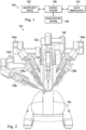
- the teleoperational surgical system 100 also includes an image capture system 106 which includes an image capture device, such as an endoscope, and related image processing hardware and software.
- the teleoperational surgical system 100 also includes a control system 108 that is operatively linked to sensors, motors, actuators, components of the master console 102, components of the slave manipulator 104 and to the image capture system 106.
- the system 100 is used by a system operator, generally a surgeon, who performs a minimally invasive surgical procedure on a patient.
- the system operator sees images, captured by the image capture system 106, presented for viewing at the master console 102.
- the control system 108 effects servomechanical movement of surgical instruments coupled to the teleoperational slave manipulator 104.
- the control system 108 includes at least one processor and typically a plurality of processors for effecting control between the master manipulator 102, the slave manipulator 104, and the image capture system 106.
- the control system 108 also includes software programming instructions to implement some or all of the methods described herein. While control system 108 is shown as a single block in the simplified schematic of FIG. 1 , the system may comprise a number of data processing circuits (e.g., on the surgeon's console 102 and/or on the slave manipulator system 104), with at least a portion of the processing optionally being performed adjacent an input device, a portion being performed adjacent a manipulator, and the like. Any of a wide variety of centralized or distributed data processing architectures may be employed.
- control system 108 may support wireless communication protocols such as Bluetooth, IrDA, HomeRF, IEEE 802.11, DECT, and Wireless Telemetry.
- FIG. 2 is a front elevation view of the patient-side manipulator 104 according to one embodiment of the teleoperational surgical system 100.
- the patient-side manipulator 104 includes a base 120 that rests on the floor, a support tower 122 that is mounted on the base 120, and several arms that support surgical tools (including portions of the image capture system 106).
- arms 124a, 124b are instrument arms that support and move the surgical instruments used to manipulate tissue
- arm 126 is a camera arm that supports and moves the endoscope.
- FIG. 2 also shows an optional third instrument arm 124c that is supported on the back side of support tower 122 and that can be positioned to either the left or right side of the patient-side manipulator as necessary to conduct a surgical procedure.
- FIG. 1 is a front elevation view of the patient-side manipulator 104 according to one embodiment of the teleoperational surgical system 100.
- the patient-side manipulator 104 includes a base 120 that rests on the floor, a support tower 122 that is mounted on the base 120
- the surgical instruments 128a, 128b, 128c include end effectors 129a, 129b, respectively. (See Fig. 11 )
- FIG. 3 is a front elevation view of a master console 102 component according to one embodiment of the teleoperational surgical system 100.
- the master console 102 is equipped with left and right multiple DOF master tool manipulators (MTM's) 132a, 132b, which are kinematic chains that are used to control the surgical tools (which include the endoscope and various cannulas).
- the MTM's 132 may be referred to simply as "master,” and their associated arms 124 and surgical instruments 128 may be referred to simply as "slave.”
- the surgeon grasps a pincher assembly 134a, 134b on each MTM 132, typically with the thumb and forefinger, and can move the pincher assembly to various positions and orientations.
- Each MTM 132a, 132b will generally allow movement within the master workspace with a plurality of degrees of freedom, typically with six degrees of freedom, three rotational degrees of freedom and three translational degrees of freedom.
- each MTM 132 is coupled to control a corresponding instrument arm 124 for the patient-side manipulator 104.
- left MTM 132a may be coupled to control instrument arm 124a and instrument 128a
- right MTM 132b may be coupled to control instrument arm 124b and instrument 128b. If the third instrument arm 124c is used during a surgical procedure and is positioned on the left side, then left MTM 132a can be switched between controlling arm 124a and instrument 128a to controlling arm 124c and instrument 128c.
- right MTM 132a can be switched between controlling arm 124b and instrument 128b to controlling arm 124c and instrument 128c.
- the third instrument arm may be controlled by either the left or right MTM to accommodate surgical convenience.
- control assignments between MTM's 132a, 132b and arm 124a/instrument 128a combination and arm 124b/instrument 128b combination may also be exchanged. This may be done, for example, if the endoscope is rolled 180 degrees, so that the instrument moving in the endoscope's field of view appears to be on the same side as the MTM the surgeon is moving.
- Surgeon's console 102 also includes a stereoscopic image display system 136.
- Left side and right side images captured by the stereoscopic endoscope 130 are output on corresponding left and right displays, which the surgeon perceives as a three-dimensional image on display system 136.
- the MTM's 132 are positioned below display system 136 so that the images of the surgical tools shown in the display appear to be co-located with the surgeon's hands below the display. This feature allows the surgeon to intuitively control the various surgical tools in the three-dimensional display as if watching the hands directly. Accordingly, the MTM servo control of the associated instrument arm and instrument is based on the endoscopic image reference frame.
- the endoscopic image reference frame (i.e., "the image frame” or the "first instrument frame") is also used if the MTM's are switched to a camera control mode. For example, if the camera control mode is selected, the surgeon may move the distal end of the endoscope by moving one or both of the MTM's together (portions of the two MTM's may be servomechanically coupled so that the two MTM portions appear to move together as a unit). The surgeon may then intuitively move (e.g., pan, tilt, zoom) the displayed stereoscopic image by moving the MTM's as if holding the image in the hands.
- the surgeon's console 102 is typically located in the same operating room as the patient-side manipulator 104, although it is positioned so that the surgeon operating the console is outside the sterile field.
- One or more assistants typically assist the surgeon by working within the sterile surgical field (e.g., to change tools on the patient side cart, to perform manual retraction, etc.). Accordingly, the surgeon operates remote from the sterile field, and so the console may be located in a separate room or building from the operating room.
- two consoles 102 may be networked together so that two surgeons can simultaneously view and control tools at the surgical site.
- FIG. 22 illustrates the slave manipulator 104 with a patient P positioned for surgery.
- the slave manipulator 104 is free-standing and the surgical instruments and the uterine elevator are all mounted to the free-standing base 120 and support tower 122. For clarity, some of the instrument arms and instruments have been omitted.
- FIG. 4 is a perspective view of a portion of the control arm 124c with the mounted surgical instrument 128c. Sterile drapes and associated mechanisms that are normally used during surgery are omitted for clarity.
- the manipulator 140 includes a yaw servo actuator 142, a pitch servo actuator 144, and an insertion and withdrawal ("I/O") actuator 146.
- the surgical instrument 128c is shown mounted at an instrument spar 148 including a mounting carriage 149.
- An illustrative straight cannula 150 is shown mounted to cannula mount 152.
- Shaft 154 of instrument 128c extends through cannula 150.
- Manipulator 140 is mechanically constrained so that it moves instrument 128c around a stationary remote center of motion 156 (also called “remote center 156") located along the instrument shaft.
- Yaw actuator 142 provides yaw motion 158 around remote center 156
- pitch actuator 144 provides pitch motion 160 around remote center 156
- I/O actuator 146 provides insertion and withdrawal motion 162 through remote center 156.
- the remote center of motion 156 is locked at the incision in the patient's body wall during surgery and to allow for sufficient yaw and pitch motion to be available to carry out the intended surgical task.
- the remote center of motion may be located outside of the body to allow a greater range of motion without contacting the patient. Knowledgeable persons will understand that motion around a remote center of motion may be constrained by the use of software or by a physical constraint defined by a mechanical assembly.
- Matching force transmission disks in mounting carriage 149 and instrument force transmission assembly 164 couple actuation forces from actuators in manipulator 140 to move various parts of instrument 128c in order to position and orient a tissue probe 166 mounted at the distal end of the curved shaft 154. Such actuation forces may typically roll instrument shaft 154 (thus providing another DOF through the remote center 156).
- Embodiments of force transmission assemblies are provided in U.S. Pat. No. 6,331,191 (filed October 15, 1999 ; disclosing "Surgical Robotic Tools, Data Architecture, and Use") and U.S. Pat. No. 6,491,701 (filed January 12, 2001 ; disclosing "Mechanical Actuator Interface System for Robotic Surgical Tools”) which are incorporated herein by reference in its entirety.
- the instrument 128c may include a wrist at the distal end of the shaft that provides additional yaw and pitch DOF's.
- the tissue probe 166 may be, for example, a general tissue manipulator, a tissue elevator, or a tissue retractor.
- the instrument 128c may include an imaging component.
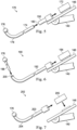
- FIG. 5 depicts an exploded schematic view of a two-piece surgical instrument 170 that may be mounted to the manipulator 140 of FIG 4 .
- the straight cannula 150 is mounted to the instrument spar 148.
- the instrument 170 includes a force transmission assembly 172, a shaft 174, and a tissue probe 176.
- the shaft 174 is a rigid rod with a curved portion 178.
- the shaft may be cannulated and/or flexible.
- the shaft 174 may be sterilizable and may include a back-loadable tissue probe or vaginal fornices delineator such as a KOH Cup produced by Cooper Surgical, Inc. of Trumbull, CT.
- the tissue probe 176 may be integrated with the shaft or may be removable and disposable.
- the instrument 170 is assembled by loading the shaft 174 through a distal end 180 of the cannula 150 and into engagement with the force transmission assembly 172. With the described configuration, any instrument insertion or removal motion may be along the instrument axis associated with spar 148.
- the curved nature of the shaft allows the instrument the versatility to manipulate tissue that is difficult to reach with a straight instrument.
- the tissue probe 176 may be a uterine elevator tip for intrauterine manipulation, but other instruments such as a vaginal fornices delineator, retractors, actuated instruments, non-actuated instruments, or imaging devices may also be used for uterine procedures or surgical procedures at other anatomical locations.
- FIG. 6 depicts an exploded schematic view of a two-piece surgical instrument 190 that may be mounted to the manipulator 140 of FIG. 4 .
- a curved cannula 192 is mounted to the instrument spar 148.
- the instrument 190 includes a force transmission assembly 194, a shaft 196, and a tissue probe 176.
- the shaft 196 is a flexible rod.
- the tissue probe 176 may be a uterine elevator tip for intrauterine manipulation, but other instruments such as vaginal fornices delineator, retractors, actuated instruments, non-actuated instruments, or imaging devices may also be used for uterine procedures or surgical procedures at other anatomical locations.
- the tissue probe 176 may be integrated with the shaft or may be removable and disposable.
- the instrument 190 is assembled by loading the shaft 196 through a distal end 200 of the curved cannula 192 and into engagement with the force transmission assembly 194.
- the flexible nature of the shaft allows it to bend for insertion through the curved cannula
- FIG. 7 depicts a schematic view of a one-piece surgical instrument 202 that may be mounted to the manipulator 140 of FIG. 4 .
- the instrument 202 includes a tissue probe 176, a curved shaft segment 204, and straight shaft segment 203 that can be mounted directly to spar 148 instead of a cannula.
- the shaft 203 is a rigid rod with a rigid curved segment 204.
- the tissue probe 176 may be a uterine elevator tip for intrauterine manipulation, but other instruments such as a vaginal fornices delineator, retractors, actuated instruments, non-actuated instruments, or imaging devices may also be used for uterine procedures or surgical procedures at other anatomical locations.
- the shaft may be cannulated and/or non-rigid.
- the tissue probe 176 may be integrated with the shaft or may removable and disposable.
- a "dummy" force transmission assembly 205 is shown attached to spar 148.
- the instrument 202 is assembled by attaching the shaft 203 directly to spar 148 in place of a cannula.
- the "dummy" force transmission assembly can be installed during operation to allow the system to recognize the type of instrument being attached via an electronic identification mechanism built into the force transmission 205 housing.
- the "dummy" force transmission assembly can thus signal that the tissue probe is ready for use in a following mode. Further description of a "dummy" or “mock” instrument is provided in U.S.
- shaft 203 may include a stop feature to prevent random rotation relative to the spar 148.
- shaft 203 may have the capability of being rotationally indexed on the axis of the shaft.
- the force transmission assembly may include a marker for determining the rotational position of the shaft 203 to aid in calculating the tissue probe 176 location.
- FIGS. 8 and 9 Another embodiment of a surgical instrument is disclosed in FIGS. 8 and 9 .
- a tissue probe is attachable to a distal end of a cannulated shaft that is mountable to an I/O insertion spar as previously described.
- FIG. 8 depicts a curved cannulated shaft 210 and a tip fastener 212 sized for insertion into a distal end 214 of the curved cannulated shaft.
- the tip fastener 212 may be mechanically coupled to the curved cannula 210 via, for example, a threaded coupling, a snap coupling, a friction coupling, or other known mechanical coupling.
- Suitable cannulated shafts may include, for example, 5 or 8mm cannulated shafts.
- tissue probe 216 is mechanically coupled to the tip fastener 212.
- the tissue probe 216 includes distal openings 218 connected to tubing 220.
- the tubing 220 is used to irrigate and suction a surgical site via the tissue probe 216.
- tissue probes may be mounted directly to cannulas mounted to the insertion spar as (such as the cannulas shown in FIG. 5 and 6a).
- the cannulas and the instrument shafts may be formed of rigid materials such as stainless steel or glass-epoxy composite.
- they may be formed of flexible materials such as a high modulus of elasticity plastic like Polyether ether ketone (PEEK), glass or carbon filled Polyether ether ketone (PEEK), or a glass-fiber-epoxy or a carbon-fiber-epoxy composite construction.
- PEEK Polyether ether ketone
- PEEK Polyether ether ketone
- PEEK polyether ether ketone
- PEEK Polyether ether ketone
- PEEK polyether ether ketone
- PEEK polyether ether ketone
- PEEK polyether ether ketone
- the inside and outside diameters and physical construction of the shaft or cannula are chosen uniquely for each material choice to limit the magnitude of forces that can be applied to the body during use or allow the structure to bend sufficiently to follow a curved guide path within the instrument or cannula during use.
- FIG. 10 schematically illustrates the master console 102.
- FIG. 11 schematically illustrates components (including instruments 130, 128a, 128b, 128c) of the slave manipulator 104.
- the surgeon views an instrument workspace 226 through the viewer of the display system 136.
- the tissue probe 166 carried on the instrument spar 148 is caused to perform positional and orientational movements within the instrument workspace 226 in response to movement and action inputs on an associated master control in a master workspace 228 (also "master space 228").
- the instrument arm 124c may be controlled by either the MTM 132a or the MTM 132b.
- the instrument arm 124c with the surgical instrument 128c including the tissue probe 166 will be controlled by the left MTM 132a.
- a different master frame of reference (X 1 , Y 1 , Z 1 ) is associated with each one of the MTMs. It is understood that other frames of reference may be defined within the master workspace. For example, a viewer frame of reference (X 4 , Y 4 , Z 4 ) may be associated with the viewer of display system 136.
- the relationships between the frames of reference in the master workspace may be established by fixed kinematic relationships, by sensors, or other known relationships.
- the surgical instrument 128c is positioned within a body cavity 230 and the tissue probe 166 is positioned against a tissue wall 232 of the body cavity 230.
- the body cavity may be any surgically created or naturally formed body cavity.
- the body cavity is the uterus of a patient and the instrument is inserted through the cervix, into the uterus, and into contact with the uterine wall.
- the tissue probe which may be a uterine elevator, serves to elevate and move the uterine tissue wall so that it will be properly positioned for access by the end effectors associated with the surgical instruments.
- tissue probe 166 is a view of the tissue probe 166 positioned against the tissue wall 232 from within the body cavity 230. This view from a position at a proximal end of the tissue probe 166 will also be described as the "probe frame” or “second instrument frame” (X 3 , Y 3 , Z 3 ) within the instrument workspace 226.
- the instrument frame may also be defined at other locations within the body cavity or at other locations along the shaft of the instrument 128c.
- images of the end effectors 129a, 129b and the surrounding instrument workspace are captured by the endoscope 130 having a field of view 131.
- These images from the viewpoint or field of view 131 of the endoscope are displayed on the display system 136 so that the surgeon sees the responsive movements and actions of the end effectors 129a, 129b as he or she controls such movements and actions by means of the MTM's 132a, 132b, respectively.
- the field of view 131 captured by the endoscope 130 has an endoscopic frame of reference (X 2 , Y 2 , Z 2 ) within the instrument workspace 226.
- visualization of the tissue probe 166 is obstructed by the tissue wall 232.
- protrusion of the tissue wall 232 and movement of the protrusion due to movement of the tissue 166 on the opposite side of the tissue wall may be visualized in the field of view 131 of endoscope 130.
- the control system 108 is arranged to cause orientational and positional movement of the tissue probe 166, as viewed in the image at the viewer of the display system 136 to be mapped by orientational and positional movement of MTM 132a of the master manipulator 102 as will be described in greater detail below.
- the probe frame, the endoscopic frame, frames of reference for each of the end effectors 129a, 129b, and any other frames of reference defined within the instrument workspace 226 may have known relationships established by fixed kinematic connections or by sensors.
- control system will be described with reference to MTM 132a and instrument arm 124c with surgical instrument 128c.
- Control between master and slave movement is achieved by comparing master position and orientation in the master workspace 228 having a master Cartesian coordinate reference system with slave position and orientation in an instrument workspace 226 having a surgical Cartesian coordinate reference system.
- Cartesian coordinate reference system will simply be referred to as "frame” in the rest of this specification.
- control system 108 serves to compare the slave position and orientation within the endoscopic frame with the master position and orientation in the master frame (and/or viewer frame) and will actuate the slave to into a position and/or orientation in the endoscopic frame that corresponds with the position and/or orientation of the master in the master frame (and/or viewer frame).
- the master frame of reference translates and rotates correspondingly.
- These master frame translations and rotations may be sensed, and they may transformed (also "mapped") to the frames of reference in the instrument workspace, including the probe frame, to provide a control relationship between the MTM and coupled instruments and/or probe in the workspace by using well known kinematic calculations.
- the frame of the coupled instrument is changed correspondingly, so that the coupled instrument movement is slaved to the MTM movement.
- control system 108 includes at least one, and typically a plurality, of processors which compute new corresponding positions and orientations of the slave in response to master movement input commands on a continual basis determined by the processing cycle rate of the control system.
- the Z 1 -axis of the master frame through the master workspace moves with the MTM 132a.
- the X 1 and Y 1 -axes extend perpendicularly from the Z 1 -axis.
- the Z 4 -axis of the viewer frame through the master workspace extends along (or parallel to) a line of sight of the surgeon, indicated by axis 242, when viewing the surgical site through the viewer of the display system 136.
- the X 4 and Y 4 -axes extend perpendicularly from the Z 4 -axis.
- the Y 4 axis is chosen to extend generally vertically relative to the viewer of the display system 136 and the X 4 axis is chosen to extend generally horizontally relative to the viewer.
- the Z 2 -axis of the endoscopic frame extends axially along (or parallel to) a viewing axis 244 of the endoscope 130.
- the viewing axis 244 is shown in coaxial alignment with a shaft axis of the endoscope 130, it is to be appreciated that the viewing axis can be angled relative thereto.
- the endoscope can be in the form of a straight or angled-tip scope.
- the X 2 and Y 2 -axes are positioned in a plane perpendicular to the Z 2 -axis. Also shown in FIG.
- the Z 3 -axis of a probe frame extends axially along (or parallel to) a longitudinal axis of the instrument 128c.
- the X 3 and Y 3 -axes are positioned in a plane perpendicular to the Z 3 -axis.
- a surgical teleoperational mapping method includes moving a MTM in a master workspace by articulating a plurality of master joints. Master control signals, corresponding to the position, orientation, and velocity of the MTM are transmitted to the control system.
- control system will generate corresponding slave motor signals to map the Cartesian position of the master in the master workspace with the Cartesian position of the end effector or tissue probe in the instrument workspace according to a transformation.
- the control system may derive the transformation in response to state variable signals provided from the image capture system so that an image of the end effector or tissue probe in the display system appears substantially connected to the MTM.
- position and velocity in the master workspace are transformed into position and velocity in the instrument workspace using scale and offset converters. Further details of the transformation are provided in U.S. Pat. No. 6,424,885 which was previously incorporated by reference herein.
- a surgical tissue probe or end effector is moved in the instrument workspace by articulating a plurality of slave joints in response to slave motor signals.
- the slave motor signals are generated by the control system in response to moving the master so that an image of the end effector or tissue probe in the display appears substantially connected with the MTM in the master workspace.
- mapping of the master to the slave would require the MTM 132a to be twisted to point back at the surgeon in an ergonomically awkward position and orientation. Therefore, a method of inverting the mapping of the master to the slave along at least one of the coordinates will allow the surgeon to control the tissue probe 166 as though the instrument 128c was extending from the tissue probe back toward the surgeon. In other words, as will be described in detail below, the movement of the MTM 132 is mapped to the tissue probe 166 in a reversed direction along at least one coordinate of the probe frame.
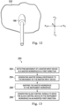
- FIG. 13 provides one example of a process 250 for controlling a surgical instrument 128c, such a uterine elevator instrument, using an inverted mapping technique.
- a surgical instrument 128c such a uterine elevator instrument
- the control system 108 will be informed that an inverted mapping technique, rather than a conventional mapping technique is required.
- This information may be based, for example, on a user input, sensor input, or other feedback identifying the slave instrument or slave arm as arranged in a configuration, such as an end-on view, in which an inverted mapping technique provides more comfortable manipulation for the user.
- an MTM 132 within the master workspace 228 typically has six degrees of freedom, three rotational degrees of freedom and three translational degrees of freedom.
- the process 250 may be performed with all six degrees of freedom enabled.
- the position of the tip of the tissue probe may be mapped without similarly mapping the orientation of the probe.
- the rotational/ orientation mapping is rendered inoperable. More specifically, the rotational degrees of freedom (yaw, pitch, and roll) may be freed to create an interface that allows the surgeon to perceive that the MTM 132a is dragging the tissue probe. Thus, the tissue probe would appear to translate through the three dimensional coordinate system, but rotational capability would be disabled, wherein the rotation of the MTM is locked out.
- the master rotation may be allowed to float, wherein the rotation is ignored in the transformation of the tissue probe manipulation.
- translation is mapped with less than all of the rotational degrees of freedom.
- translation of the MTM may be mapped with rotation about a Z-axis, without mapping the movement about the X- and Y- axes. Any error between the master and probe with respect to non-active axes may be omitted from display to avoid the need for remapping of the MTM.
- a master input device namely MTM 132a
- movement of a master input device namely MTM 132a
- the movement of the MTM 132a results in the generation of master control signals.
- the movement of the MTM 132a in the master workspace 228 is mapped to the tissue probe 166 in the instrument workspace.
- slave control signals are generated to move the tissue probe 166 in the instrument workspace, in an inverted first direction.
- An inverted direction is reversed or opposite in magnitude along at least one axis of the Cartesian coordinate system.
- the scale of movement, velocity, and size of the workspace may be controlled based upon the tissue probe used. Limits on the motion of the tissue, e.g. the uterus, may be predetermined and set by the system or by the surgeon's visual cues.
- the movement of the master input device in the master workspace may be mapped to instruments in the instrument workspace based upon a determination of the slave instrument insertion direction. For example, if the slave instrument is inserted into the instrument workspace in a direction that corresponds with the direction of the field of view, a mapping associated with the direction of the field of view may be used. Alternatively, if the slave instrument is inserted into the instrument workspace in a direction that is non-corresponding with the direction of the field of view, a different mapping, such as one including an inversion for at least one direction of the slave instrument motion may be used.
- a slave instrument insertion direction may be considered “corresponding” based on a geometric relationship between the viewing axis of the imaging instrument and the slave instrument as determined by known kinematic relationship or sensor feedback.
- a corresponding slave instrument direction may be any direction that is less than or equal to ninety degrees (or, in other embodiments, less than ninety degrees) from the viewing axis (e.g. axis 244).
- instruments 128a and 128b may be considered to be inserted in a corresponding direction because of their direction relative to the viewing axis 244.
- a slave instrument direction may also be considered “non-corresponding" based on a geometric relationship between the viewing axis of the imaging instrument and the slave instrument.
- a non-corresponding slave instrument direction may be any direction that is greater than ninety degrees (or, in other embodiments, no less than ninety degrees) from the viewing axis.
- instrument 128c may be considered to be inserted in a non-corresponding direction because of it has an insertion direction approximately 180° from the viewing angle 244 and is not extending between the viewing angle 244 and a plane perpendicular to the distal tip of the imaging instrument 130.
- instruments 128a, 128b may have a corresponding mapping that corresponds to the field of view along the viewing axis 244, and instrument 128c may have a mapping that includes an inversion of the corresponding mapping in at least one direction of motion (e.g., the X 3 direction) for the instrument 128c.
- the inversion may be, for example an opposite or 180° change in direction from the corresponding mapping.
- the view of the instrument workspace 226 through the endoscope 130 allows the user at the master console 102 to visualize the section of tissue wall 232, the instrument 128a with end effector 129a, and the instrument 128b with end effector 129b.
- the tissue probe 166 in the workspace may not be directly visualized due to the intervening tissue 232, the general location of the tip may be identified by a protrusion, distension, or other quality associated with an area of the tissue 232 that has been elevated by the tip.
- an overlay image may be displayed to indicate the location of the tip. This overlay may be triggered when control is switched to the tissue probe.
- the tissue may be visualized directly, providing an internal view of the patient anatomy.
- the +X 2 direction is to the right of the page
- the -X 2 direction is to the left of the page
- the +Y 2 direction is to the top of the page
- the -Y 2 direction is to the bottom of the page
- the +Z 2 direction is out of the page
- the -Z 2 direction is into the page.
- the surgeon may be primarily interested in the amount of tissue stretch achieved by the probe and will move the probe until the image in the endoscopic frame indicates that the tissue of interest is stretched to the surgeon's specifications.
- the probe frame of the instrument workspace 226 from the opposite side of the tissue wall 232 inverts the X and Z axes as compared to the endoscopic frame (X 2 , Y 2 , Z 2 ).
- the -X 3 direction is to the left of the page
- the +X 3 direction is to the right of the page
- the +Y 3 direction is to the top of the page
- the -Y 3 direction is to the bottom of the page
- the -Z 3 direction is into the page
- the +Z 3 direction is out of the page.
- the surgeon wishes to move the tissue probe 166 toward the location of the end effector 129b, as shown in FIG. 16 , he or she moves the MTM 132a in the +X 4 direction (toward the MTM 132b in the master space 228). Because of the inverted position (non-corresponding direction) of the instrument 128c, under a conventional, non-inverted mapping scheme, movement of the MTM 132a to the right toward the MTM 132b in the master space 228 would cause the tissue probe 166 in the view of FIG. 17 to also move to the right -- in the +X 3 direction toward the end effector 129a.
- the mapping of the MTM 132a is inverted.
- movement of the MTM 132a in the +X 4 direction in the master workspace 228 is inverted in the probe frame, causing the tissue probe 166 to move in the -X 3 direction (i.e. opposite the +X 3 direction), toward the end effector 129b in the endoscopic frame.
- control system 108 may be configured to determine if the MTM 132a is communicatively coupled with a slave instrument in a corresponding direction such as an instrument 128a, 128b, 130 (i.e. an instrument other than the tissue probe 166), and if so movement of the MTM 132a in the viewer frame is mapped to movement of the slave instrument in the endoscopic frame according to a first mapping.
- the first mapping translates movement in a first direction (e.g., to the viewer's right, +X 4 ) in the viewer frame to movement in the first direction (e.g., to the endoscope's right, +X 2 ) in the endoscopic frame.
- the MTM 132a is communicatively coupled with a slave instrument in a non-corresponding direction, such as the inverted instrument 128c that includes the tissue probe 166
- movement of the MTM 132a in the viewer frame is mapped to movement of the inverted instrument in the probe frame according to a second mapping.
- the second mapping translates the movement in the first direction (e.g. to the viewer's right, +X 4 ) in the viewer frame to movement in an inverted first direction (e.g. to the tissue probe's left, -X 3 , as viewed from a proximal location along the shaft of instrument 128c) in the probe frame.
- the inverted first direction e.g.
- the probe frame in the probe frame is opposite the first direction (e.g., +X 4 ) in the viewer frame and in the endoscopic frame.
- movement of the instrument 128c in the inverted first direction of the probe frame is in the same direction in the instrument workspace as the first direction of the instrument 128a in the endoscopic frame.
- the first direction +X 2 in the endoscopic frame is the same as the inverted first direction -X 3 in the probe frame.
- FIGS. 18 and 19 a starting position of the tissue probe 166 as in FIGS. 14 and 15 is assumed. If the surgeon wishes to move the tissue probe 166 up, he or she moves the MTM 132a in the +Y 4 direction (out of the page in the master space 228 of FIG. 10 ). In this example, a conventional mapping scheme may be used because an upward movement of the MTM 132a in the master space 228 would cause the tissue probe 166 in the view of FIG. 19 to also move up-- in the +Y 3 direction. In other words, the "up" movement is the same in both the endoscopic view of FIG. 18 and in the instrument view of FIG. 19 . Thus, conventional mapping will result in movement of the tissue probe 166 in the +Y 2 direction and the +Y 3 direction when the MTM 132a is moved in the +Y 4 direction.
- control system 108 may be configured to determine if the MTM 132a is communicatively coupled with a slave instrument in a corresponding direction such as an instrument 128a, 128b, 130 (i.e. an instrument other than the tissue probe 166), and if so movement of the MTM 132a in the viewer frame is mapped to movement of the first slave instrument in the endoscopic frame according to a first mapping.
- the first mapping translates movement in a first direction (e.g., to the viewer's up, +Y 4 ) in the viewer frame to movement in the first direction (e.g., to the endoscope's up, +Y 2 ) in the endoscopic frame.
- the MTM 132a is communicatively coupled with a slave instrument in a non-corresponding direction, such as the instrument 128c that includes the tissue probe 166
- movement of the MTM 132a in the viewer frame is mapped to movement of the slave instrument in the probe frame according to a second mapping.
- the second transformation also translates the movement in the first direction (e.g. to the viewer's up, +Y 4 ) in the viewer frame to movement in a first direction (e.g. to the tissue probe's up, +Y 3 , as viewed from a proximal location along the shaft of instrument 128c) in the probe frame.
- the first direction e.g.
- the probe frame +Y 3 ) in the probe frame is the same as the first direction (e.g., +Y 4 ) in the viewer frame.
- movement of the instrument 128c in the first direction of the probe frame is in the same direction in the instrument workspace as the first direction of the instrument 128a in the endoscopic frame.
- the first direction +Y 2 in the endoscopic frame is the same as the inverted first direction +Y 3 in the probe frame.
- FIGS. 20 and 21 a starting position of the tissue probe 166 as in FIGS. 14 and 15 is assumed. If the MTM 132a is coupled to move the tissue probe 166 and the surgeon wishes to move the tissue probe 166 away from the tissue wall 232, he or she moves the MTM 132a along the -Z 4 direction and away from the viewer of the display system 136 in FIG. 10 . Because of the inverted position (non-corresponding direction) of the instrument 128c, under a conventional mapping scheme, movement of the MTM 132a away from the surgeon in the -Z 4 direction in the master space 228 would cause the tissue probe 166 in the view of FIG.
- the mapping of the MTM 132a is inverted.
- movement of the MTM 132a in the -Z 4 direction in the master workspace 228 is inverted, causing the tissue probe 166 to move in the +Z 3 direction (i.e. opposite the -Z 4 direction), out of the page and away from the tissue wall 232 (toward the cervix in the probe frame).
- control system 108 may be configured to determine if the MTM 132a is communicatively coupled with a slave instrument in a corresponding direction such as an instrument 128a, 128b, 130 (i.e. an instrument other than the tissue probe 166), and if so movement of the MTM 132a in the viewer frame is mapped to movement of the first slave instrument in the endoscopic frame according to a first mapping.
- the first mapping translates movement in a first direction (e.g., away from the viewer, -Z 4 ) in the viewer frame to movement in the first direction (e.g., away from the endoscope, -Z 2 ) in the endoscopic frame.
- the MTM 132a is communicatively coupled with a slave instrument in a non-corresponding direction, such as the instrument 128c that includes the tissue probe 166
- movement of the MTM 132a in the viewer frame is mapped to movement of the second slave instrument in the probe frame according to a second mapping.
- the second mapping translates the movement in the first direction (e.g. away from the viewer, -Z 4 ) in the viewer frame to movement in an inverted first direction (e.g. away from the tissue wall 232, +Z 3 , as viewed from a proximal location along the shaft of instrument 128c) in the probe frame.
- the inverted first direction e.g.
- the +Z 3 ) in the probe frame is opposite the first direction (e.g., -Z 4 ) in the viewer frame and the endoscopic frame.
- movement of the instrument 128c in the inverted first direction of the probe frame is in the same direction in the instrument workspace as the first direction of the instrument 128a in the endoscopic frame.
- the first direction -Z 2 in the endoscopic frame is the same as the inverted first direction +Z 3 in the probe frame.
- angular movements of the MTM 132a in the three dimensional workspace 228 may also be mapped to the three dimensional instrument workspace such that the mapping is inverted as to one or more of the coordinate axes and conventional as to one or more of the coordinate axes.
- a movement +X 4 , +Y 4 in the viewer and endoscopic frames, may be mapped to correspond to a movement -X 3 , +Y 3 , in a probe frame.
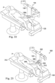
- FIG. 23 illustrates an alternative slave manipulator system 300.
- the system 300 includes separate teleoperated manipulator component 302 and manipulator component 304. Both components 302, 304 may be operated via a common master manipulator and control system. Alternatively, they may be operated by different master manipulators, direct manipulators, and/or control systems.
- Manipulator component 302 is substantially similar to the patient-side manipulator described for FIG. 2 , including the surgical instruments that operate under master control.
- Manipulator component 304 is a separate servo-operated manipulator and includes a mounted instrument 306 with tissue probe 308, similar to any of the embodiments described above. In this embodiment, the manipulator component 304 is mounted to a bed rail 310 of a patient bed 312.
- the initial positioning of the manipulator component 304 may be performed manually.
- the manipulator component 304 may be moved along the bed rail 310 and locked in place with a friction locking mechanism.
- the manipulator component 304 may be placed under the control of the master manipulator and central control system.
- the mounted instrument 306 with tissue probe 308 may be operated as described for earlier embodiments.
- the manipulator component may be mounted on any side of the patient bed or on another movable or stationary component in the surgical arena.
- FIGS. 24-26 illustrate an assisting medical instrument 400, such as a uterine elevator, according to another embodiment.
- the instrument 400 may be attached to the instrument spar 148 of FIG. 4 .
- the instrument 400 has a proximal end 402 and a distal end 404.
- the proximal end includes a handle 406 that may be used to manually manipulate the instrument when disconnected from the instrument spar 148.
- the handle 406 has an ergonomic grip to allow a user to grasp and manipulate the instrument when not under teleoperational control.
- the instrument 400 further includes a mounting portion 408 sized and shaped to mate with the cannula mount 152.
- the mounting portion 408 includes a recessed surface 410 that provides identification information indicating characteristics of the instrument such as size and shape.
- the identification information may be located on a different portion of the instrument.
- the identification information may be read or otherwise sensed at the instrument spar 148 and electronically communicated from the instrument to the control system 108.
- the instrument 400 further includes a fixed curved shaft portion 412 having an approximately 90° arc and a fixed radius of curvature.
- the curved portion has an arc length.
- the curved portion 412 and other portions of the instrument 400 may be formed of a rigid material including metals such as stainless steel or titanium, polymers such polyetheretherketone (PEEK), or ceramics. Suitable materials may be light weight but have sufficient strength to resist substantial bending or breaking when a force is applied to the instrument to manipulate tissue in a patient anatomy.
- the curved portion 412 has a solid shaft but in alternative embodiments may be cannulated to reduce weight or to provide passage for fluid flow or other medical tools.
- the distal end 404 of the instrument 400 includes a tip fastener 414 and the curved shaft portion 412 includes channels, grooves, fasteners and other mating features 416.
- the fastener 414 and mating features 416 are sized and shaped to mate with a medical accessory 418.
- the medical accessory 418 include a tissue probe 419.
- the tissue probe 419 may be rounded, flexible, inflatable, and/or have other atraumatic tip characteristics that allow the probe to engage and apply force to tissue without tearing, abrading, or otherwise damaging the tissue.
- Various medical accessories suitable for use with the instrument 400 are available from CooperSurgical, Inc. of Trumbull, CT and may include uterine manipulator accessories from the RUMI ® and Koh product lines.
- the instrument 400 When attached to the instrument spar 148, the instrument 400 may be controlled to pivot about a center of rotation C1 disposed along an axis A1 (perpendicular to the page in FIG. 24 ) which does not intersect the instrument 400.
- the instrument 400 may be constrained to single rotational degree of freedom (e.g. pitch).
- the center of rotation C1 is locked at the patient orifice during surgery and allows for sufficient pitch motion to be available to carry out the intended surgical manipulation.
- the center of rotation may be located outside of the body to allow a greater range of motion without contacting the patient.
- Knowledgeable persons will understand that motion around a center of rotation may be constrained by the use of software or by a physical constraint defined by a mechanical assembly.
- a location feature 420 is provided on the mounting portion 408 to indicate to a user the direction of the instrument curvature when the curved portion of the instrument is located inside of a patient anatomy and thus is not visible to the user.
- the location feature 420 may also serve to prevent the instrument 400 from rotating about an axis A2 extending through the mounting portion 408, thus maintaining the center of rotation C1 in a fixed position relative to the instrument spar 148.
- the location feature 420 is a projection, but in alternative embodiments may be a marking, a recessed portion or other indicating feature.
- the instrument 400 is attached to the cannula mount 152.
- a "dummy" force transmission assembly FIG. 7
- the medical accessory 418 is mated with the curved shaft portion 412 and is coupled to the distal end 404.
- the assembled instrument 400 is positioned within a body cavity with the tissue probe 419 positioned against a tissue wall of the body cavity.
- the tissue probe may be, for example, expanded by inflation with a fluid.
- the instrument may be positioned through a patient orifice first and then may be coupled to the manipulator after the instrument is in position.
- the manipulator 140 may be attached to the patient bed, to a movable support structure, or to another fixed or movable component in the surgical area.
- movement of the instrument 400 along the X 3 axis is restricted and movement of the instrument in the Y 3 and Z 3 directions is coupled due to the constrained rotational movement of the instrument 400 about the center of rotation C1.
- the distal end 404 of the instrument 400 is pivoted forward (clockwise in FIG. 24 ) about the center of rotation C1 (i.e. a pitch motion about axis A1), the distal end 404 moves in a +Y 3 , -Z 3 direction.
- the distal end 404 is pivoted in reverse (counter-clockwise in FIG. 24 ) about the center of rotation C1
- the distal end 404 moves in a - Y 3 , +Z 3 direction.
- the movement of the MTM 132a that controls the motion of the tissue probe may likewise be coupled in the Y 1 and Z 1 directions.
- the movement of the MTM 132a that controls the motion of the tissue probe may be decoupled in the Y1 and Z1 directions.
- the decoupled movement of the MTM 132a is mapped to approximate MTM movement while accommodating the coupled movement of the instrument.
- a conventional mapping scheme may be used because an upward movement of the MTM 132a in the master space 228 would cause the tissue probe 419 to also move up-- in the +Y 3 direction.
- the "up" movement is the same in both the endoscopic view and in the instrument view.
- conventional mapping will result in movement of the tissue probe 419 in the +Y 3 direction when the MTM 132a is moved in the +Y 1 direction. If the surgeon wishes to move the tissue probe 419 away from the tissue wall 232 ( FIG.
- FIGS. 27 and 28 illustrate an assisting medical instrument 450, such as a uterine elevator, according to another embodiment.
- the medical instrument 450 may be similar in configuration and operation to the instrument 400, with a few distinguishing features as will be described.
- the medical instrument 450 includes a proximal end 452, a distal end 454, and a curved shaft portion 456 extending between the proximal and distal ends.
- a straight shaft portion 458 extends between the proximal end 452 and the curved shaft portion 456.
- the instrument 450 When attached to the instrument spar 148, the instrument 450 may pivot about a center of rotation C2.
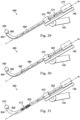
- FIG. 29 is a schematic view of an assisting medical instrument 460 that may be mounted to the manipulator 140 of FIG. 4 in a configuration that provides additional degrees of freedom of motion for the tissue probe.
- the instrument 460 has a proximal end 462, a distal end 464, a curved shaft portion 466, and a straight shaft portion 468.
- a tissue probe 469 is mounted to the distal end 464.
- An axis A3 extends through the straight shaft portion 468.
- the instrument spar 148 of the manipulator 140 includes an instrument anchor 470.
- the instrument anchor 470 includes a passageway sized to receive the straight shaft portion 468 to couple instrument 460 to the instrument spar 148.
- the instrument anchor 470 may be an accessory clamp as described in greater detail in U.S. Pat.
- the instrument anchor 470 may serve as a bearing which permits linear translation of the instrument 460 along the axis A3 and rotational motion of the instrument about the axis A3, while constraining translational motion perpendicular to the axis A3.
- a force transmission assembly 472 (substantially similar to force transmission assembly 164 described above) couples actuation forces from actuators in manipulator 140 to move various parts of instrument 460 in order to position and orient the tissue probe 469 mounted at the distal end of the curved shaft 466.
- a joint 474 such as a quick disconnect mechanism, extends between the proximal and distal ends of the instrument 460. In this embodiment, the joint 474 is between the instrument anchor 470 and the force transmission assembly 472. Alternatively, the joint may extend between the proximal end of the instrument and the force transmission assembly. The joint 474 allows for rotation of the tissue probe 469 about the axis A3 at the j oint.
- the j oint 474 may also or alternatively allow for translation of the tissue probe along the axis A3 from the joint. Additionally, the joint 474 permits quick exchange of the distal end of the instrument 460 and the tissue probe 469. For example, joint 474 allows a non-sterile end effector or tissue probe on a distal end of the instrument to be removed from the sterile proximal end portions of the instrument. Furthermore, the joint 474 allows for set-up of the instrument 460 and tissue probe 469 within the patient anatomy without the encumbrance of an attached manipulator. For example, the instrument 460 and tissue probe 469 may be positioned and arranged within the patient body cavity.
- the instrument spar 148 with force transmission assembly 472 is introduced to the instrument 460.
- the straight shaft portion 468 is loaded into the instrument anchor 470, for example, through a distal opening in the instrument anchor or through an opening between pivoting clamp arms.
- the force transmission assembly 472 may then be operatively coupled to the straight shaft portion via the joint 474.
- the force transmission assembly 472 is operable to control the rotational movement of the tissue probe 469 about the axis A3 and to control the translation of the tissue probe along the axis A3.
- the straight shaft portion between the joint and the curved shaft portion may have a smaller diameter than the straight shaft portion between the joint and the force transmission assembly to permit telescoping motion.
- the instrument anchor 470 may operate as a bearing to support the rotational and translational motion of the straight portion of the shaft.
- FIG. 30 is a schematic view of an assisting medical instrument 480 that may be mounted to the manipulator 140 of FIG. 4 in a configuration that provides additional degrees of freedom of motion for the tissue probe.
- the instrument 480 may be substantially similar to the instrument 460 and configuration of FIG. 29 with the differences to be described.
- the instrument 480 has a proximal end 482, a distal end 484, a curved shaft portion 486, a straight shaft portion 488, and a tissue probe 490.
- a joint 492 such as a quick disconnect j oint, is engaged between the distal end 484 and the instrument anchor 470.
- the joint 492 allows for rotation of the tissue probe 490 and curved portion 486 about the axis A4 at the joint.
- the joint 492 also allows for translation of the tissue probe along the axis A4 from the joint.
- the joint 492 permits quick exchange of the distal end 484 of the instrument and the tissue probe 490.
- the joint 492 allows for set-up of the instrument 480 and tissue probe 490 within the patient anatomy without the encumbrance of an attached manipulator.
- assembly of the instrument 480 may be less cumbersome that the assembly of the instrument 460 ( FIG. 29 ) because the straight shaft portion may be connected to the joint without the need to feed the straight shaft portion through the instrument anchor.
- the joint 492 is distal of the instrument anchor, the joint should be selected to withstand the tissue probing forces without deformation.
- the straight shaft portions on either side of the joint may remain generally collinear and aligned with the axis A4.
- the joint may be capable of withstanding loads of up to approximately 30 lbs.
- FIG. 31 is a schematic view of an assisting medical instrument 500 that may be mounted to the manipulator 140 of FIG. 4 in a configuration that provides additional degrees of freedom of motion for the tissue probe.
- the instrument 500 may be substantially similar to the instrument 480 and configuration of FIG. 30 with the differences to be described.
- the instrument 500 rather than a quick disconnect joint 474, the instrument 500 has a proximal end 502, a distal end 504, a curved shaft portion 506, a straight shaft portion 508, and a tissue probe 510.
- a joint 512 such as a multi-dimensional wrist joint, is between the distal end 504 and the instrument anchor 470.
- An example of various multi-dimensional wrist joints are described in greater detail in U.S. Pat. No.
- the joint 512 allows for multi-dimensional movement of the tissue probe 510 and curved portion 506. Because the joint 512 is distal of the instrument anchor, the joint should be selected to withstand the tissue probing forces without deformation. With a sufficiently robust j oint, the straight shaft portions on either side of the joint remain generally collinear and aligned with the axis A4. For example, the joint may be capable of withstanding loads of up to approximately 30 lbs.
- FIG. 32 illustrates an assisting medical instrument 550 including a passive illumination source.
- the medical instrument 550 may be, for example, a uterine elevator similar to any of the embodiments previously described.
- the instrument 550 may be attached to the instrument spar 148 of FIG. 4 .
- the instrument 550 includes a probe portion 552 coupled to a distal end of a shaft portion 554.
- the probe portion 552 and or the shaft portion 554 may include one or more illumination fiducial markers 556.
- the illumination fiducial markers 556 may be passive illumination fiducial markers that operate without connection to a power mains or to an energy storage device such as a battery. Passive illumination fiducial markers receive incident light from a light source and in response, emit light.
- a passive illumination fiducial marker may include a passive light emitting diode (LED) system.
- a passive LED system may include a photosensor coupled to an LED. The photosensor receives excitation light and generates current to illuminate the LED.
- a passive illumination fiducial marker may include a well, a channel, a recess, or other cavity or container for containing a fluorescent dye such as indocyanine green (ICG) dye.
- ICG indocyanine green
- Light received from an external source may illuminate the passive marker either directly or through occluding tissue.
- an external source such as light delivered by an optical fiber to a surgical area
- the passive marker may pass through the tissue wall to excite the passive marker on the probe.
- the excited passive marker emits light that may be visible to a user via the endoscope.
- the location of the probe may be recognized, through the occluding tissue, from the light of the passive marker.
- the excitation light may be supplied by a light source on either the probe side or the end effector side of the tissue wall.
- the markers may be active illumination fiducial markers, including a battery or other power supply to power an LED or other light source.
- FIGS. 33-34 illustrate another example of a medical implement that may be fitted with passive illumination markers.
- a colpotomizer cup 560 includes passive illumination markers 562.
- the colpotomizer cup 560 When used in a medical procedure such as a hysterectomy, the colpotomizer cup 560 may be positioned at the base of a uterus 564. Light from an endoscope 566 or other light source may pass through a wall 568 of the uterus 564 to excite one or more of the markers 562. Light emitted from the excited markers 562 may then be visible through the wall 568 via the endoscope 566. The excited markers 562 may thus serve as a guide for the medical instrument 570 to perform a medical procedure such as an ablation or an incision.
- the ring of markers may serve as a guide for cutting the tissue adjacent to the lip of the cup.
- Passive markers 574 may also be located on a uterine probe 572, including on an inflatable portion of the probe. Such markers may aid in defining the endometrium and fibroid tumors to allow for safer myomectomy procedures.
- Passive markers such as those described, may be used in a variety of medical procedures to identify instruments, implants, target locations, or leave-behind guides or indicators where occluding tissue would otherwise obstruct direct visualization by an image capture system, a visualization system, or the naked eye.
- Uterine manipulation may be used in a hysterectomy procedure or in the treatment of endometriosis to provide constant stable tension to enable precise dissection. Teleoperational control of uterine manipulation may also be particularly useful in cases in which the manual manipulation of a large uterus would lead to user fatigue.
- uterine manipulators may be used to move the transaction place away from vital structures such as ureters.
- Teleoperational uterine manipulation is also useful for improving the surgical autonomy of the console surgeon.
- the surgeon controls the position exactly to their liking without interacting with or waiting for the patient side assistant.
- the patient side assistant may be providing surgical assistance instead of holding the manipulator.
- Teleoperational uterine manipulation may also avoid the patient side assistant from becoming contaminated due to movement between the equipment arms.
- any reference to surgical instruments and surgical methods is non-limiting as the instruments and methods described herein may be used for animals, human cadavers, animal cadavers, portions of human or animal anatomy, non-surgical diagnosis, industrial systems, and general robotic or teleoperational systems.
- One or more elements in embodiments of the invention may be implemented in software to execute on a processor of a computer system such as control system 108.
- the elements of the embodiments of the invention are essentially the code segments to perform the necessary tasks.
- the program or code segments can be stored in a processor readable storage medium or device that may have been downloaded by way of a computer data signal embodied in a carrier wave over a transmission medium or a communication link.
- the processor readable storage device may include any medium that can store information including an optical medium, semiconductor medium, and magnetic medium.
- Processor readable storage device examples include an electronic circuit; a semiconductor device, a semiconductor memory device, a read only memory (ROM), a flash memory, an erasable programmable read only memory (EPROM); a floppy diskette, a CD-ROM, an optical disk, a hard disk, or other storage device,
- the code segments may be downloaded via computer networks such as the Internet, Intranet, etc.
Landscapes
- Health & Medical Sciences (AREA)
- Engineering & Computer Science (AREA)
- Surgery (AREA)
- Life Sciences & Earth Sciences (AREA)
- Medical Informatics (AREA)
- General Health & Medical Sciences (AREA)
- Veterinary Medicine (AREA)
- Public Health (AREA)
- Biomedical Technology (AREA)
- Heart & Thoracic Surgery (AREA)
- Nuclear Medicine, Radiotherapy & Molecular Imaging (AREA)
- Molecular Biology (AREA)
- Animal Behavior & Ethology (AREA)
- Robotics (AREA)
- Mechanical Engineering (AREA)
- Gynecology & Obstetrics (AREA)
- Pregnancy & Childbirth (AREA)
- Reproductive Health (AREA)
- Oral & Maxillofacial Surgery (AREA)
- Pathology (AREA)
- Manipulator (AREA)
- Surgical Instruments (AREA)
- Endoscopes (AREA)
Abstract
Description
- This patent application claims priority to and the benefit of the filing date of
U.S. Provisional Patent Application 62/362,406, entitled "SYSTEMS AND METHODS FOR CONTROLLING A SURGICAL INSTRUMENT," filed July 14, 2016 - The present disclosure is directed to robotic systems and methods of use, including surgical systems and methods for use in minimally invasive teleoperational surgery, and including systems and methods for controlling an instrument for uterine manipulation.
- Minimally invasive medical techniques are intended to reduce the amount of extraneous tissue that is damaged during diagnostic or surgical procedures, thereby reducing patient recovery time, discomfort, and harmful side effects. Minimally invasive telesurgical systems have been developed to increase a surgeon's dexterity and to avoid some of the limitations on traditional minimally invasive techniques. In telesurgery, the surgeon uses some form of remote control, e.g., a servomechanism or the like, to manipulate surgical instrument movements, rather than directly holding and moving the instruments by hand. In telesurgery systems, the surgeon can be provided with an image of the surgical site at the surgical workstation. While viewing a two or three dimensional image of the surgical site on a display, the surgeon performs the surgical procedures on the patient by manipulating master control devices, which in turn control motion of the servomechanically operated instruments.
- In robotically-assisted telesurgery, the surgeon typically operates a master controller to control the motion of surgical instruments at the surgical site from a location that may be remote from the patient (e.g., across the operating room, in a different room, or a completely different building from the patient). The master controller usually includes one or more hand input devices, such as hand-held wrist gimbals, joysticks, exoskeletal gloves or the like, which are operatively coupled to the surgical instruments that are releasably coupled to a patient side "slave" surgical manipulator. The configuration and motion of the master controls the instrument's position, orientation, and articulation at the surgical site via the patient side "slave" surgical manipulator. The slave is an electro-mechanical assembly which includes a plurality of arms, joints, linkages, servo motors, etc. that are connected together to support and control the surgical instruments. In a surgical procedure, the surgical instruments (including an endoscope) may be introduced directly into an open surgical site or more typically through cannulas into a body cavity.
- For minimally invasive surgical procedures, the surgical instruments, controlled by the surgical manipulator, may be introduced into the body cavity through a single surgical incision site or through multiple closely spaced incision sites on the patient's body. For some minimally invasive surgical procedures, surgical instruments, particularly surgical assist tools such as probes, tissue manipulators, and retractors, may also be introduced into the surgical workspace through more remotely located surgical incisions or natural orifices. Improved systems and methods are needed for mounting and controlling these surgical instruments.
- The instruments, systems, and methods described herein may be used for non-medical purposes including industrial uses, general robotic uses, manipulation of non-tissue work pieces, and/or cosmetic improvements. Other non-surgical applications include use on tissue removed from human or animal anatomies (without return to a human or animal anatomy) or on human or animal cadavers.
- The embodiments of the invention are summarized by the claims that follow below.
- In one embodiment, a teleoperational medical system comprises an input device and a manipulator configured to couple with and move an instrument. The system also comprises a control system including one or more processors. In response to a determination that the instrument is inserted into an instrument workspace in a corresponding direction to a field of view of the workspace, the control system is configured to map movement of the input device to movement of the instrument according to a first mapping. In response to a determination that the instrument is inserted into the instrument workspace in a non-corresponding direction to the field of view, the control system is configured to map movement of the input device to movement of the instrument according to a second mapping. The second mapping includes an inversion of the first mapping for at least one direction of motion of the instrument.
- In another embodiment, a method comprises generating master control signals based on a movement of a master controller in a master workspace and determining a direction of a field of view of an imaging device in an instrument workspace. The method also comprises determining whether a slave instrument direction for a slave instrument in the instrument workspace is corresponding to the direction of the field of view or is non-corresponding to the direction of the field of view. In response to a determination that the slave instrument direction is corresponding to the direction of the field of view, the method comprises mapping the movement of the master controller to movement of the slave instrument according to a first mapping and generating slave instrument control signals for movement of the slave instrument in the instrument workspace based on the first mapping. In response to a determination that the slave instrument direction is non-corresponding to the direction of the field of view, the method comprises mapping the movement of the master controller to movement of the slave instrument according to a second mapping and generating slave instrument control signals for movement of the slave instrument in the instrument workspace based on the second mapping. The second mapping includes an inversion of the first mapping for at least one direction of motion of the slave instrument.
- In another embodiment, a teleoperational instrument system comprises a master input device in a master workspace, an actuated instrument end effector in an instrument workspace, and an actuated tissue probe in the instrument workspace. A method of operating the teleoperational instrument system comprises generating a set of master control signals in response to movement of the master input device and responsive to the set of master control signals, generating a first mapping. The first mapping maps the movement of the master input device to movement of the instrument end effector in the instrument workspace. Responsive to the set of master control signals, the method also comprises generating a second mapping. The second mapping maps the movement of the master input device to movement of the actuated tissue probe in the instrument workspace. In response to a determination that the master input device has control of the actuated instrument end effector, the method also includes generating a set of instrument control signals using the first mapping. In response to a determination that the master input device has control of the actuated tissue probe, the method comprises generating a set of instrument control signals using the second mapping. The second mapping includes an inversion of the first mapping for at least one direction of motion of the actuated tissue probe.
- Aspects of the present disclosure are best understood from the following detailed description when read with the accompanying figures. It is emphasized that, in accordance with the standard practice in the industry, various features are not drawn to scale. In fact, the dimensions of the various features may be arbitrarily increased or reduced for clarity of discussion. In addition, the present disclosure may repeat reference numerals and/or letters in the various examples. This repetition is for the purpose of simplicity and clarity and does not in itself dictate a relationship between the various embodiments and/or configurations discussed.
-
FIG. 1 is a schematic depiction of a teleoperational system according to an embodiment of the present disclosure. -
FIG. 2 is a front elevation view of a patient side cart including three patient side manipulators and one endoscopic manipulator according to one embodiment of the disclosure. -
FIG. 3 is a front elevation view of a surgeon's console in a teleoperational surgical system according to one embodiment of the disclosure. -
FIG. 4 is a perspective view of a patient side manipulator arm with a mounted surgical instrument according to one embodiment of the disclosure. -
FIG. 5 is an exploded schematic view of a uterine elevator, cannula, and surgical manipulator according to one embodiment of the disclosure. -
FIG. 6 is an exploded schematic view of a uterine elevator, cannula, and surgical manipulator according to a second embodiment of the disclosure. -
FIG. 7 is an exploded schematic view of a uterine elevator, cannula, and surgical manipulator according to a third embodiment of the disclosure. -
FIG. 8 is a side view of a tool fastener for use with a curved cannula. -
FIG. 9 is a side view of a uterine elevator for use with the tool fastener and curved cannula ofFIG. 8 . -
FIG. 10 is a schematic view of a surgeon's control console relative to a controller's three dimensional Cartesian coordinate reference system in a controller's workspace. The Cartesian coordinate reference frame shown in the figure has the Y-axis extending normal to and away from the plane of the page and is indicated with a solid dot in the center of the reference frame symbol. This labeling convention is used for all subsequent figures. -
FIG. 11 is a schematic view of surgical instruments (including an endoscope) relative to a surgical three dimensional Cartesian coordinate reference system in an instrument workspace. -
FIG. 12 is a view of an elevator instrument positioned within a body cavity. -
FIG. 13 is a process for controlling a surgical instrument, such an elevator instrument, using an inverted mapping technique. -
FIG. 14 is an endoscopic user view of an instrument workspace with a uterine elevator instrument (shown with phantom lines to indicate that it is obscured from view) in a first position relative to a section of tissue. In this view, the uterine elevator instrument is behind tissue and is not directly visible via the endoscope. -
FIG. 15 is a view of the instrument workspace ofFIG. 14 with the uterine elevator instrument in the first position, from the probe frame. -
FIG. 16 is an endoscopic user view of the instrument workspace with the uterine elevator instrument (shown with phantom lines) in a second position relative to the section of tissue. -
FIG. 17 is a view of the instrument workspace ofFIG. 16 with the uterine elevator instrument in the second position, from the probe frame. -
FIG. 18 is an endoscopic user view of the instrument workspace with the uterine elevator instrument (shown with phantom lines) in a third position relative to the section of tissue. -
FIG. 19 is a view of the instrument workspace ofFig. 18 with the uterine elevator instrument in the third position, from the probe frame. -
FIG. 20 is an endoscopic user view of the instrument workspace with the uterine elevator instrument (shown with phantom lines) in a fourth position relative to the section of tissue. -
FIG. 21 is a view of the instrument workspace ofFIG. 20 with the uterine elevator instrument in the fourth position, from the probe frame. -
FIG. 22 is a schematic view of a free-standing slave manipulator with a mounted uterine elevator instrument. -
FIG. 23 is a schematic view of a bed-mounted slave manipulator with a mounted uterine elevator instrument. -
FIG. 24 is a side view of an assisting medical instrument according to an embodiment of the disclosure. -
FIG. 25 is a rear view of the assisting medical instrument ofFIG. 24 . -
FIG. 26 is a front view of the assisting medical instrument ofFIG. 24 . -
FIG. 27 is a side view of an assisting medical instrument according to another embodiment of the disclosure. -
FIG. 28 is a front view of the assisting medical instrument ofFIG. 27 . -
FIG. 29 is a schematic view of an assisting medical instrument with a joint assembly and a force transmission assembly according to one embodiment of the disclosure. -
FIG. 30 is a schematic view of an assisting medical instrument with a joint assembly, and a force transmission assembly according to another embodiment of the disclosure. -
FIG. 31 is a schematic view of an assisting medical instrument with a joint assembly, and a force transmission assembly according to still another embodiment of the disclosure. -
FIG. 32 illustrates an assisting medical instrument including a passive illumination source. -
FIG. 33 illustrates a colpotomizer cup including a passive illumination source. -
FIG. 34 illustrates the colpotomizer cup ofFIG. 33 in use in a medical procedure. - In the following detailed description of the embodiments of the invention, numerous specific details are set forth in order to provide a thorough understanding of the disclosed embodiments. However, it will be obvious to one skilled in the art that the embodiments of this disclosure may be practiced without these specific details. In other instances well known methods, procedures, components, and circuits have not been described in detail so as not to unnecessarily obscure aspects of the embodiments of the invention.
- Referring to
FIG. 1 of the drawings, a teleoperational system is generally indicated by thereference numeral 100. The teleoperationalsurgical system 100 includes amaster console 102, also referred to as a master or surgeon's console, for inputting a surgical procedure and aslave manipulator 104, also referred to as a patient-side manipulator (PSM), for the teleoperational movement of surgical instruments at a surgical site within a patient. The teleoperationalsurgical system 100 is used to perform minimally invasive teleoperational surgery. One example of a teleoperational surgical system that can be used to implement the systems and techniques described in this disclosure is a da Vinci® Surgical System manufactured by Intuitive Surgical, Inc. of Sunnyvale, California. In one embodiment the slave manipulator may be free-standing (see,FIG. 2 ). In an alternative embodiment, the slave manipulator may be mounted to other equipment in the surgical arena, including, for example, the surgical bed (see,FIG. 23 ). In still another alternative embodiment, the slave manipulator may include both free-standing and bed-mounted components. - The teleoperational
surgical system 100 also includes animage capture system 106 which includes an image capture device, such as an endoscope, and related image processing hardware and software. The teleoperationalsurgical system 100 also includes acontrol system 108 that is operatively linked to sensors, motors, actuators, components of themaster console 102, components of theslave manipulator 104 and to theimage capture system 106. - The
system 100 is used by a system operator, generally a surgeon, who performs a minimally invasive surgical procedure on a patient. The system operator sees images, captured by theimage capture system 106, presented for viewing at themaster console 102. In response to the surgeon's input commands, thecontrol system 108 effects servomechanical movement of surgical instruments coupled to theteleoperational slave manipulator 104. - The
control system 108 includes at least one processor and typically a plurality of processors for effecting control between themaster manipulator 102, theslave manipulator 104, and theimage capture system 106. Thecontrol system 108 also includes software programming instructions to implement some or all of the methods described herein. Whilecontrol system 108 is shown as a single block in the simplified schematic ofFIG. 1 , the system may comprise a number of data processing circuits (e.g., on the surgeon'sconsole 102 and/or on the slave manipulator system 104), with at least a portion of the processing optionally being performed adjacent an input device, a portion being performed adjacent a manipulator, and the like. Any of a wide variety of centralized or distributed data processing architectures may be employed. Similarly, the programming code may be implemented as a number of separate programs or subroutines, or may be integrated into a number of other aspects of the teleoperational systems described herein. In one embodiment,control system 108 may support wireless communication protocols such as Bluetooth, IrDA, HomeRF, IEEE 802.11, DECT, and Wireless Telemetry. -
FIG. 2 is a front elevation view of the patient-side manipulator 104 according to one embodiment of the teleoperationalsurgical system 100. The patient-side manipulator 104 includes a base 120 that rests on the floor, asupport tower 122 that is mounted on thebase 120, and several arms that support surgical tools (including portions of the image capture system 106). As shown inFIG. 2 ,arms arm 126 is a camera arm that supports and moves the endoscope.FIG. 2 also shows an optionalthird instrument arm 124c that is supported on the back side ofsupport tower 122 and that can be positioned to either the left or right side of the patient-side manipulator as necessary to conduct a surgical procedure.FIG. 2 further shows interchangeablesurgical instruments instrument arms endoscope 130 mounted on thecamera arm 126. Knowledgeable persons will appreciate that the arms that support the instruments and the camera may also be supported by a base platform (fixed or moveable) mounted to a ceiling or wall, or in some instances to another piece of equipment in the operating room (e.g., the operating table). Likewise, they will appreciate that two or more separate bases may be used (e.g., one base supporting each arm). Thesurgical instruments end effectors Fig. 11 ) -
FIG. 3 is a front elevation view of amaster console 102 component according to one embodiment of the teleoperationalsurgical system 100. Themaster console 102 is equipped with left and right multiple DOF master tool manipulators (MTM's) 132a, 132b, which are kinematic chains that are used to control the surgical tools (which include the endoscope and various cannulas). The MTM's 132 may be referred to simply as "master," and their associated arms 124 and surgical instruments 128 may be referred to simply as "slave." The surgeon grasps apincher assembly MTM - When a tool control mode is selected, each MTM 132 is coupled to control a corresponding instrument arm 124 for the patient-
side manipulator 104. For example, leftMTM 132a may be coupled to controlinstrument arm 124a andinstrument 128a, andright MTM 132b may be coupled to controlinstrument arm 124b andinstrument 128b. If thethird instrument arm 124c is used during a surgical procedure and is positioned on the left side, then leftMTM 132a can be switched between controllingarm 124a andinstrument 128a to controllingarm 124c andinstrument 128c. Likewise, if thethird instrument arm 124c is used during a surgical procedure and is positioned on the right side, thenright MTM 132a can be switched between controllingarm 124b andinstrument 128b to controllingarm 124c andinstrument 128c. In alternative embodiments, the third instrument arm may be controlled by either the left or right MTM to accommodate surgical convenience. In some instances, control assignments between MTM's 132a, 132b andarm 124a/instrument 128a combination andarm 124b/instrument 128b combination may also be exchanged. This may be done, for example, if the endoscope is rolled 180 degrees, so that the instrument moving in the endoscope's field of view appears to be on the same side as the MTM the surgeon is moving. - Surgeon's
console 102 also includes a stereoscopicimage display system 136. Left side and right side images captured by thestereoscopic endoscope 130 are output on corresponding left and right displays, which the surgeon perceives as a three-dimensional image ondisplay system 136. In one configuration, the MTM's 132 are positioned belowdisplay system 136 so that the images of the surgical tools shown in the display appear to be co-located with the surgeon's hands below the display. This feature allows the surgeon to intuitively control the various surgical tools in the three-dimensional display as if watching the hands directly. Accordingly, the MTM servo control of the associated instrument arm and instrument is based on the endoscopic image reference frame. - The endoscopic image reference frame (i.e., "the image frame" or the "first instrument frame") is also used if the MTM's are switched to a camera control mode. For example, if the camera control mode is selected, the surgeon may move the distal end of the endoscope by moving one or both of the MTM's together (portions of the two MTM's may be servomechanically coupled so that the two MTM portions appear to move together as a unit). The surgeon may then intuitively move (e.g., pan, tilt, zoom) the displayed stereoscopic image by moving the MTM's as if holding the image in the hands.
- The surgeon's
console 102 is typically located in the same operating room as the patient-side manipulator 104, although it is positioned so that the surgeon operating the console is outside the sterile field. One or more assistants typically assist the surgeon by working within the sterile surgical field (e.g., to change tools on the patient side cart, to perform manual retraction, etc.). Accordingly, the surgeon operates remote from the sterile field, and so the console may be located in a separate room or building from the operating room. In some implementations, two consoles 102 (either co-located or remote from one another) may be networked together so that two surgeons can simultaneously view and control tools at the surgical site. -
FIG. 22 illustrates theslave manipulator 104 with a patient P positioned for surgery. In this embodiment, theslave manipulator 104 is free-standing and the surgical instruments and the uterine elevator are all mounted to the free-standingbase 120 andsupport tower 122. For clarity, some of the instrument arms and instruments have been omitted. -
FIG. 4 is a perspective view of a portion of thecontrol arm 124c with the mountedsurgical instrument 128c. Sterile drapes and associated mechanisms that are normally used during surgery are omitted for clarity. Themanipulator 140 includes ayaw servo actuator 142, apitch servo actuator 144, and an insertion and withdrawal ("I/O")actuator 146. Thesurgical instrument 128c is shown mounted at aninstrument spar 148 including a mountingcarriage 149. An illustrativestraight cannula 150 is shown mounted tocannula mount 152.Shaft 154 ofinstrument 128c extends throughcannula 150.Manipulator 140 is mechanically constrained so that it movesinstrument 128c around a stationary remote center of motion 156 (also called "remote center 156") located along the instrument shaft. Yaw actuator 142 providesyaw motion 158 aroundremote center 156,pitch actuator 144 providespitch motion 160 aroundremote center 156, and I/O actuator 146 provides insertion andwithdrawal motion 162 throughremote center 156. Typically the remote center ofmotion 156 is locked at the incision in the patient's body wall during surgery and to allow for sufficient yaw and pitch motion to be available to carry out the intended surgical task. Alternatively, the remote center of motion may be located outside of the body to allow a greater range of motion without contacting the patient. Knowledgeable persons will understand that motion around a remote center of motion may be constrained by the use of software or by a physical constraint defined by a mechanical assembly. - Matching force transmission disks in mounting
carriage 149 and instrumentforce transmission assembly 164 couple actuation forces from actuators inmanipulator 140 to move various parts ofinstrument 128c in order to position and orient atissue probe 166 mounted at the distal end of thecurved shaft 154. Such actuation forces may typically roll instrument shaft 154 (thus providing another DOF through the remote center 156). Embodiments of force transmission assemblies are provided inU.S. Pat. No. 6,331,191 (filed October 15, 1999 ; disclosing "Surgical Robotic Tools, Data Architecture, and Use") andU.S. Pat. No. 6,491,701 (filed January 12, 2001 ; disclosing "Mechanical Actuator Interface System for Robotic Surgical Tools") which are incorporated herein by reference in its entirety. In alternative embodiments, theinstrument 128c may include a wrist at the distal end of the shaft that provides additional yaw and pitch DOF's. Thetissue probe 166 may be, for example, a general tissue manipulator, a tissue elevator, or a tissue retractor. In alternative embodiments, theinstrument 128c may include an imaging component. -
FIG. 5 depicts an exploded schematic view of a two-piecesurgical instrument 170 that may be mounted to themanipulator 140 ofFIG 4 . In this embodiment, thestraight cannula 150 is mounted to theinstrument spar 148. Theinstrument 170 includes aforce transmission assembly 172, ashaft 174, and atissue probe 176. In this embodiment, theshaft 174 is a rigid rod with acurved portion 178. In alternative embodiments, the shaft may be cannulated and/or flexible. Theshaft 174 may be sterilizable and may include a back-loadable tissue probe or vaginal fornices delineator such as a KOH Cup produced by Cooper Surgical, Inc. of Trumbull, CT. Thetissue probe 176 may be integrated with the shaft or may be removable and disposable. Theinstrument 170 is assembled by loading theshaft 174 through adistal end 180 of thecannula 150 and into engagement with theforce transmission assembly 172. With the described configuration, any instrument insertion or removal motion may be along the instrument axis associated withspar 148. The curved nature of the shaft allows the instrument the versatility to manipulate tissue that is difficult to reach with a straight instrument. In one embodiment, thetissue probe 176 may be a uterine elevator tip for intrauterine manipulation, but other instruments such as a vaginal fornices delineator, retractors, actuated instruments, non-actuated instruments, or imaging devices may also be used for uterine procedures or surgical procedures at other anatomical locations. -
FIG. 6 depicts an exploded schematic view of a two-piecesurgical instrument 190 that may be mounted to themanipulator 140 ofFIG. 4 . In this embodiment, acurved cannula 192 is mounted to theinstrument spar 148. Theinstrument 190 includes aforce transmission assembly 194, ashaft 196, and atissue probe 176. In this embodiment, theshaft 196 is a flexible rod. In one embodiment, thetissue probe 176 may be a uterine elevator tip for intrauterine manipulation, but other instruments such as vaginal fornices delineator, retractors, actuated instruments, non-actuated instruments, or imaging devices may also be used for uterine procedures or surgical procedures at other anatomical locations. Thetissue probe 176 may be integrated with the shaft or may be removable and disposable. Theinstrument 190 is assembled by loading theshaft 196 through adistal end 200 of thecurved cannula 192 and into engagement with theforce transmission assembly 194. The flexible nature of the shaft allows it to bend for insertion through the curved cannula. -
FIG. 7 depicts a schematic view of a one-piecesurgical instrument 202 that may be mounted to themanipulator 140 ofFIG. 4 . In this embodiment, theinstrument 202 includes atissue probe 176, acurved shaft segment 204, andstraight shaft segment 203 that can be mounted directly to spar 148 instead of a cannula. In this embodiment, theshaft 203 is a rigid rod with a rigidcurved segment 204. In one embodiment, thetissue probe 176 may be a uterine elevator tip for intrauterine manipulation, but other instruments such as a vaginal fornices delineator, retractors, actuated instruments, non-actuated instruments, or imaging devices may also be used for uterine procedures or surgical procedures at other anatomical locations. To accommodate actuated instruments, the shaft may be cannulated and/or non-rigid. Thetissue probe 176 may be integrated with the shaft or may removable and disposable. Instead of theforce transmission assembly 194 ofFIG 4 , a "dummy"force transmission assembly 205 is shown attached to spar 148. Theinstrument 202 is assembled by attaching theshaft 203 directly to spar 148 in place of a cannula. The "dummy" force transmission assembly can be installed during operation to allow the system to recognize the type of instrument being attached via an electronic identification mechanism built into theforce transmission 205 housing. The "dummy" force transmission assembly can thus signal that the tissue probe is ready for use in a following mode. Further description of a "dummy" or "mock" instrument is provided inU.S. Provisional Application 61/594,130 (filed February 2, 2012 shaft 203 may include a stop feature to prevent random rotation relative to thespar 148. Alternatively,shaft 203 may have the capability of being rotationally indexed on the axis of the shaft. Alternatively, the force transmission assembly may include a marker for determining the rotational position of theshaft 203 to aid in calculating thetissue probe 176 location. - Another embodiment of a surgical instrument is disclosed in
FIGS. 8 and 9 . In this embodiment, a tissue probe is attachable to a distal end of a cannulated shaft that is mountable to an I/O insertion spar as previously described. Specifically,FIG. 8 depicts a curved cannulatedshaft 210 and atip fastener 212 sized for insertion into adistal end 214 of the curved cannulated shaft. Thetip fastener 212 may be mechanically coupled to thecurved cannula 210 via, for example, a threaded coupling, a snap coupling, a friction coupling, or other known mechanical coupling. Suitable cannulated shafts may include, for example, 5 or 8mm cannulated shafts. Larger or smaller cannulated shafts may also be suitable within the anatomical constraints of the patient. As shown inFIG. 9 , atissue probe 216 is mechanically coupled to thetip fastener 212. Thetissue probe 216 includesdistal openings 218 connected totubing 220. Thetubing 220 is used to irrigate and suction a surgical site via thetissue probe 216. In alternative embodiments where I/O motion is not required, tissue probes may be mounted directly to cannulas mounted to the insertion spar as (such as the cannulas shown inFIG. 5 and 6a). - In the above described embodiments, the cannulas and the instrument shafts may be formed of rigid materials such as stainless steel or glass-epoxy composite. Alternatively, they may be formed of flexible materials such as a high modulus of elasticity plastic like Polyether ether ketone (PEEK), glass or carbon filled Polyether ether ketone (PEEK), or a glass-fiber-epoxy or a carbon-fiber-epoxy composite construction. The inside and outside diameters and physical construction of the shaft or cannula are chosen uniquely for each material choice to limit the magnitude of forces that can be applied to the body during use or allow the structure to bend sufficiently to follow a curved guide path within the instrument or cannula during use. Additional information about the cannulas and instrument shafts, including information about material composition and flexibility, is provided in detail in
U.S. Patent Application No. 12/618,608 (filed Nov. 13, 2009 -
FIG. 10 schematically illustrates themaster console 102.FIG. 11 schematically illustrates components (includinginstruments slave manipulator 104. As shown inFIG. 10 , the surgeon views aninstrument workspace 226 through the viewer of thedisplay system 136. Thetissue probe 166 carried on theinstrument spar 148 is caused to perform positional and orientational movements within theinstrument workspace 226 in response to movement and action inputs on an associated master control in a master workspace 228 (also "master space 228"). As previously described, theinstrument arm 124c may be controlled by either theMTM 132a or theMTM 132b. In this illustrative embodiment, theinstrument arm 124c with thesurgical instrument 128c including thetissue probe 166 will be controlled by theleft MTM 132a. A different master frame of reference (X1, Y1, Z1) is associated with each one of the MTMs. It is understood that other frames of reference may be defined within the master workspace. For example, a viewer frame of reference (X4, Y4, Z4) may be associated with the viewer ofdisplay system 136. The relationships between the frames of reference in the master workspace may be established by fixed kinematic relationships, by sensors, or other known relationships. - As shown in
FIG. 11 , during the surgical set-up procedure, thesurgical instrument 128c is positioned within abody cavity 230 and thetissue probe 166 is positioned against atissue wall 232 of thebody cavity 230. The body cavity may be any surgically created or naturally formed body cavity. In one embodiment, for example, the body cavity is the uterus of a patient and the instrument is inserted through the cervix, into the uterus, and into contact with the uterine wall. During gynecological procedures, the tissue probe, which may be a uterine elevator, serves to elevate and move the uterine tissue wall so that it will be properly positioned for access by the end effectors associated with the surgical instruments.FIG. 12 is a view of thetissue probe 166 positioned against thetissue wall 232 from within thebody cavity 230. This view from a position at a proximal end of thetissue probe 166 will also be described as the "probe frame" or "second instrument frame" (X3, Y3, Z3) within theinstrument workspace 226. The instrument frame may also be defined at other locations within the body cavity or at other locations along the shaft of theinstrument 128c. - During a surgical procedure, images of the
end effectors endoscope 130 having a field ofview 131. These images from the viewpoint or field ofview 131 of the endoscope are displayed on thedisplay system 136 so that the surgeon sees the responsive movements and actions of theend effectors - The field of
view 131 captured by theendoscope 130 has an endoscopic frame of reference (X2, Y2, Z2) within theinstrument workspace 226. In this field of view, visualization of thetissue probe 166 is obstructed by thetissue wall 232. However, protrusion of thetissue wall 232 and movement of the protrusion due to movement of thetissue 166 on the opposite side of the tissue wall may be visualized in the field ofview 131 ofendoscope 130. Thecontrol system 108 is arranged to cause orientational and positional movement of thetissue probe 166, as viewed in the image at the viewer of thedisplay system 136 to be mapped by orientational and positional movement ofMTM 132a of themaster manipulator 102 as will be described in greater detail below. - The probe frame, the endoscopic frame, frames of reference for each of the
end effectors instrument workspace 226 may have known relationships established by fixed kinematic connections or by sensors. - In the description which follows, the control system will be described with reference to
MTM 132a andinstrument arm 124c withsurgical instrument 128c. Control between master and slave movement is achieved by comparing master position and orientation in themaster workspace 228 having a master Cartesian coordinate reference system with slave position and orientation in aninstrument workspace 226 having a surgical Cartesian coordinate reference system. For ease of understanding and economy of words, the term "Cartesian coordinate reference system" will simply be referred to as "frame" in the rest of this specification. Accordingly, thecontrol system 108 serves to compare the slave position and orientation within the endoscopic frame with the master position and orientation in the master frame (and/or viewer frame) and will actuate the slave to into a position and/or orientation in the endoscopic frame that corresponds with the position and/or orientation of the master in the master frame (and/or viewer frame). As an MTM is translated and rotated in three dimensional space, the master frame of reference translates and rotates correspondingly. These master frame translations and rotations may be sensed, and they may transformed (also "mapped") to the frames of reference in the instrument workspace, including the probe frame, to provide a control relationship between the MTM and coupled instruments and/or probe in the workspace by using well known kinematic calculations. As the master frame position and orientation is changed, the frame of the coupled instrument is changed correspondingly, so that the coupled instrument movement is slaved to the MTM movement. - As previously described, the
control system 108 includes at least one, and typically a plurality, of processors which compute new corresponding positions and orientations of the slave in response to master movement input commands on a continual basis determined by the processing cycle rate of the control system. - As shown in
FIG. 10 , The Z1-axis of the master frame through the master workspace moves with theMTM 132a. Naturally, the X1 and Y1-axes extend perpendicularly from the Z1-axis. Also as shown inFIG. 10 , the Z4-axis of the viewer frame through the master workspace extends along (or parallel to) a line of sight of the surgeon, indicated byaxis 242, when viewing the surgical site through the viewer of thedisplay system 136. Naturally, the X4 and Y4-axes extend perpendicularly from the Z4-axis. Conveniently, the Y4 axis is chosen to extend generally vertically relative to the viewer of thedisplay system 136 and the X4 axis is chosen to extend generally horizontally relative to the viewer. - As shown in
FIG. 11 , the Z2-axis of the endoscopic frame extends axially along (or parallel to) aviewing axis 244 of theendoscope 130. Although inFIG. 11 , theviewing axis 244 is shown in coaxial alignment with a shaft axis of theendoscope 130, it is to be appreciated that the viewing axis can be angled relative thereto. Thus, the endoscope can be in the form of a straight or angled-tip scope. The X2 and Y2-axes are positioned in a plane perpendicular to the Z2-axis. Also shown inFIG. 11 , the Z3-axis of a probe frame extends axially along (or parallel to) a longitudinal axis of theinstrument 128c. The X3 and Y3-axes are positioned in a plane perpendicular to the Z3-axis. - Additional information about a referenced control system, including information about the mapping of the position and orientation of the master in the master workspace with the instrument in the instrument workspace, is provided in detail in U.S. Patent No.
US 6,424,885 B1 (filed Aug. 13, 1999 ; disclosing "Camera Referenced Control in a Minimally Invasive Surgical Apparatus") which is incorporated herein by reference, in its entirety. Generally, a surgical teleoperational mapping method includes moving a MTM in a master workspace by articulating a plurality of master joints. Master control signals, corresponding to the position, orientation, and velocity of the MTM are transmitted to the control system. In general, the control system will generate corresponding slave motor signals to map the Cartesian position of the master in the master workspace with the Cartesian position of the end effector or tissue probe in the instrument workspace according to a transformation. The control system may derive the transformation in response to state variable signals provided from the image capture system so that an image of the end effector or tissue probe in the display system appears substantially connected to the MTM. Additionally, position and velocity in the master workspace are transformed into position and velocity in the instrument workspace using scale and offset converters. Further details of the transformation are provided inU.S. Pat. No. 6,424,885 which was previously incorporated by reference herein. A surgical tissue probe or end effector is moved in the instrument workspace by articulating a plurality of slave joints in response to slave motor signals. The slave motor signals are generated by the control system in response to moving the master so that an image of the end effector or tissue probe in the display appears substantially connected with the MTM in the master workspace. - Because the surgeon has a distal end-on view of the
tissue probe 166 through thedisplay system 136, conventional mapping of the master to the slave would require theMTM 132a to be twisted to point back at the surgeon in an ergonomically awkward position and orientation. Therefore, a method of inverting the mapping of the master to the slave along at least one of the coordinates will allow the surgeon to control thetissue probe 166 as though theinstrument 128c was extending from the tissue probe back toward the surgeon. In other words, as will be described in detail below, the movement of the MTM 132 is mapped to thetissue probe 166 in a reversed direction along at least one coordinate of the probe frame. - In a conventional mapping technique, movement of the
MTM 132a in a +X4 direction results in a corresponding movement (including scaling and offset factors) ofinstrument 128a in a +X2 direction in the instrument workspace in the endoscopic frame. If the user wishes to relinquish control ofinstrument 128a and initiate control ofinstrument 128c using MTM 132a, the user registers the indication with thecontrol system 108 and the control ofMTM 132a is transferred toinstrument 128c. -
FIG. 13 provides one example of aprocess 250 for controlling asurgical instrument 128c, such a uterine elevator instrument, using an inverted mapping technique. Prior to implementation of the inverted mapping technique, thecontrol system 108 will be informed that an inverted mapping technique, rather than a conventional mapping technique is required. This information may be based, for example, on a user input, sensor input, or other feedback identifying the slave instrument or slave arm as arranged in a configuration, such as an end-on view, in which an inverted mapping technique provides more comfortable manipulation for the user. As previously described, an MTM 132 within themaster workspace 228 typically has six degrees of freedom, three rotational degrees of freedom and three translational degrees of freedom. Theprocess 250 may be performed with all six degrees of freedom enabled. In an alternative embodiment, the position of the tip of the tissue probe may be mapped without similarly mapping the orientation of the probe. In other words, the rotational/ orientation mapping is rendered inoperable. More specifically, the rotational degrees of freedom (yaw, pitch, and roll) may be freed to create an interface that allows the surgeon to perceive that theMTM 132a is dragging the tissue probe. Thus, the tissue probe would appear to translate through the three dimensional coordinate system, but rotational capability would be disabled, wherein the rotation of the MTM is locked out. Alternatively, the master rotation may be allowed to float, wherein the rotation is ignored in the transformation of the tissue probe manipulation. In still another alternative, translation is mapped with less than all of the rotational degrees of freedom. For example, translation of the MTM may be mapped with rotation about a Z-axis, without mapping the movement about the X- and Y- axes. Any error between the master and probe with respect to non-active axes may be omitted from display to avoid the need for remapping of the MTM. - At a
process 252, movement of a master input device, namelyMTM 132a, in a first direction in themaster workspace 228 is detected. At aprocess 254, the movement of theMTM 132a results in the generation of master control signals. At aprocess 256, the movement of theMTM 132a in themaster workspace 228 is mapped to thetissue probe 166 in the instrument workspace. At aprocess 258, slave control signals are generated to move thetissue probe 166 in the instrument workspace, in an inverted first direction. An inverted direction is reversed or opposite in magnitude along at least one axis of the Cartesian coordinate system. The scale of movement, velocity, and size of the workspace may be controlled based upon the tissue probe used. Limits on the motion of the tissue, e.g. the uterus, may be predetermined and set by the system or by the surgeon's visual cues. - As explained further in the detailed examples provided in
FIGS. 14-21 , the movement of the master input device in the master workspace may be mapped to instruments in the instrument workspace based upon a determination of the slave instrument insertion direction. For example, if the slave instrument is inserted into the instrument workspace in a direction that corresponds with the direction of the field of view, a mapping associated with the direction of the field of view may be used. Alternatively, if the slave instrument is inserted into the instrument workspace in a direction that is non-corresponding with the direction of the field of view, a different mapping, such as one including an inversion for at least one direction of the slave instrument motion may be used. - A slave instrument insertion direction may be considered "corresponding" based on a geometric relationship between the viewing axis of the imaging instrument and the slave instrument as determined by known kinematic relationship or sensor feedback. A corresponding slave instrument direction may be any direction that is less than or equal to ninety degrees (or, in other embodiments, less than ninety degrees) from the viewing axis (e.g. axis 244). In
FIG. 11 ,instruments viewing axis 244. A slave instrument direction may also be considered "non-corresponding" based on a geometric relationship between the viewing axis of the imaging instrument and the slave instrument. A non-corresponding slave instrument direction may be any direction that is greater than ninety degrees (or, in other embodiments, no less than ninety degrees) from the viewing axis. InFIG. 11 ,instrument 128c may be considered to be inserted in a non-corresponding direction because of it has an insertion direction approximately 180° from theviewing angle 244 and is not extending between theviewing angle 244 and a plane perpendicular to the distal tip of theimaging instrument 130. Thus inFIG. 11 ,instruments viewing axis 244, andinstrument 128c may have a mapping that includes an inversion of the corresponding mapping in at least one direction of motion (e.g., the X3 direction) for theinstrument 128c. The inversion may be, for example an opposite or 180° change in direction from the corresponding mapping. - Referring now to
FIG. 14 , the view of theinstrument workspace 226 through theendoscope 130, i.e., the endoscopic frame, allows the user at themaster console 102 to visualize the section oftissue wall 232, theinstrument 128a withend effector 129a, and theinstrument 128b withend effector 129b. Although thetissue probe 166 in the workspace may not be directly visualized due to the interveningtissue 232, the general location of the tip may be identified by a protrusion, distension, or other quality associated with an area of thetissue 232 that has been elevated by the tip. In one embodiment, an overlay image may be displayed to indicate the location of the tip. This overlay may be triggered when control is switched to the tissue probe. If an imaging probe is used, the tissue may be visualized directly, providing an internal view of the patient anatomy. In this example frame, the +X2 direction is to the right of the page, the -X2 direction is to the left of the page, the +Y2 direction is to the top of the page, the -Y2 direction is to the bottom of the page, the +Z2 direction is out of the page, and the -Z2 direction is into the page. In an alternative embodiment, the surgeon may be primarily interested in the amount of tissue stretch achieved by the probe and will move the probe until the image in the endoscopic frame indicates that the tissue of interest is stretched to the surgeon's specifications. - Referring now to
FIG. 15 , the probe frame of theinstrument workspace 226 from the opposite side of the tissue wall 232 (e.g., from a proximal end of theinstrument 128c, as viewed from the cervix into the uterus) inverts the X and Z axes as compared to the endoscopic frame (X2, Y2, Z2). Specifically, in this example frame, the -X3 direction is to the left of the page, the +X3 direction is to the right of the page, the +Y3 direction is to the top of the page, the -Y3 direction is to the bottom of the page, the -Z3 direction is into the page, and the +Z3 direction is out of the page. - If the
MTM 132a is coupled to move thetissue probe 166, and the surgeon wishes to move thetissue probe 166 toward the location of theend effector 129b, as shown inFIG. 16 , he or she moves theMTM 132a in the +X4 direction (toward theMTM 132b in the master space 228). Because of the inverted position (non-corresponding direction) of theinstrument 128c, under a conventional, non-inverted mapping scheme, movement of theMTM 132a to the right toward theMTM 132b in themaster space 228 would cause thetissue probe 166 in the view ofFIG. 17 to also move to the right -- in the +X3 direction toward theend effector 129a. To avoid this reversed outcome and to move thetissue probe 166 toward theintended end effector 129b, the mapping of theMTM 132a is inverted. Thus, as shown inFIG. 16 , movement of theMTM 132a in the +X4 direction in themaster workspace 228 is inverted in the probe frame, causing thetissue probe 166 to move in the -X3 direction (i.e. opposite the +X3 direction), toward theend effector 129b in the endoscopic frame. - More specifically, the
control system 108 may be configured to determine if theMTM 132a is communicatively coupled with a slave instrument in a corresponding direction such as aninstrument MTM 132a in the viewer frame is mapped to movement of the slave instrument in the endoscopic frame according to a first mapping. The first mapping translates movement in a first direction (e.g., to the viewer's right, +X4) in the viewer frame to movement in the first direction (e.g., to the endoscope's right, +X2) in the endoscopic frame. If theMTM 132a is communicatively coupled with a slave instrument in a non-corresponding direction, such as theinverted instrument 128c that includes thetissue probe 166, movement of theMTM 132a in the viewer frame is mapped to movement of the inverted instrument in the probe frame according to a second mapping. The second mapping translates the movement in the first direction (e.g. to the viewer's right, +X4) in the viewer frame to movement in an inverted first direction (e.g. to the tissue probe's left, -X3, as viewed from a proximal location along the shaft ofinstrument 128c) in the probe frame. The inverted first direction (e.g. -X3) in the probe frame is opposite the first direction (e.g., +X4) in the viewer frame and in the endoscopic frame. In this embodiment, movement of theinstrument 128c in the inverted first direction of the probe frame is in the same direction in the instrument workspace as the first direction of theinstrument 128a in the endoscopic frame. In other words, in theinstrument workspace 226, the first direction +X2 in the endoscopic frame is the same as the inverted first direction -X3 in the probe frame. - Referring now to
FIGS. 18 and 19 , in another example, a starting position of thetissue probe 166 as inFIGS. 14 and 15 is assumed. If the surgeon wishes to move thetissue probe 166 up, he or she moves theMTM 132a in the +Y4 direction (out of the page in themaster space 228 ofFIG. 10 ). In this example, a conventional mapping scheme may be used because an upward movement of theMTM 132a in themaster space 228 would cause thetissue probe 166 in the view ofFIG. 19 to also move up-- in the +Y3 direction. In other words, the "up" movement is the same in both the endoscopic view ofFIG. 18 and in the instrument view ofFIG. 19 . Thus, conventional mapping will result in movement of thetissue probe 166 in the +Y2 direction and the +Y3 direction when theMTM 132a is moved in the +Y4 direction. - More specifically, the
control system 108 may be configured to determine if theMTM 132a is communicatively coupled with a slave instrument in a corresponding direction such as aninstrument MTM 132a in the viewer frame is mapped to movement of the first slave instrument in the endoscopic frame according to a first mapping. The first mapping translates movement in a first direction (e.g., to the viewer's up, +Y4) in the viewer frame to movement in the first direction (e.g., to the endoscope's up, +Y2) in the endoscopic frame. If theMTM 132a is communicatively coupled with a slave instrument in a non-corresponding direction, such as theinstrument 128c that includes thetissue probe 166, movement of theMTM 132a in the viewer frame is mapped to movement of the slave instrument in the probe frame according to a second mapping. The second transformation also translates the movement in the first direction (e.g. to the viewer's up, +Y4) in the viewer frame to movement in a first direction (e.g. to the tissue probe's up, +Y3, as viewed from a proximal location along the shaft ofinstrument 128c) in the probe frame. The first direction (e.g. +Y3) in the probe frame is the same as the first direction (e.g., +Y4) in the viewer frame. In this embodiment, movement of theinstrument 128c in the first direction of the probe frame is in the same direction in the instrument workspace as the first direction of theinstrument 128a in the endoscopic frame. In other words, in theinstrument workspace 226, the first direction +Y2 in the endoscopic frame is the same as the inverted first direction +Y3 in the probe frame. - Referring now to
FIGS. 20 and 21 , in another example, a starting position of thetissue probe 166 as inFIGS. 14 and 15 is assumed. If theMTM 132a is coupled to move thetissue probe 166 and the surgeon wishes to move thetissue probe 166 away from thetissue wall 232, he or she moves theMTM 132a along the -Z4 direction and away from the viewer of thedisplay system 136 inFIG. 10 . Because of the inverted position (non-corresponding direction) of theinstrument 128c, under a conventional mapping scheme, movement of theMTM 132a away from the surgeon in the -Z4 direction in themaster space 228 would cause thetissue probe 166 in the view ofFIG. 21 to move into the page -- in the -Z3 direction further into thetissue wall 232. To avoid this reversed outcome and to move thetissue probe 166, as intended, away from thetissue wall 232, the mapping of theMTM 132a is inverted. Thus, as shown inFIGS. 20 , movement of theMTM 132a in the -Z4 direction in themaster workspace 228 is inverted, causing thetissue probe 166 to move in the +Z3 direction (i.e. opposite the -Z4 direction), out of the page and away from the tissue wall 232 (toward the cervix in the probe frame). - More specifically, the
control system 108 may be configured to determine if theMTM 132a is communicatively coupled with a slave instrument in a corresponding direction such as aninstrument MTM 132a in the viewer frame is mapped to movement of the first slave instrument in the endoscopic frame according to a first mapping. The first mapping translates movement in a first direction (e.g., away from the viewer, -Z4) in the viewer frame to movement in the first direction (e.g., away from the endoscope, -Z2) in the endoscopic frame. If theMTM 132a is communicatively coupled with a slave instrument in a non-corresponding direction, such as theinstrument 128c that includes thetissue probe 166, movement of theMTM 132a in the viewer frame is mapped to movement of the second slave instrument in the probe frame according to a second mapping. The second mapping translates the movement in the first direction (e.g. away from the viewer, -Z4) in the viewer frame to movement in an inverted first direction (e.g. away from thetissue wall 232, +Z3, as viewed from a proximal location along the shaft ofinstrument 128c) in the probe frame. The inverted first direction (e.g. +Z3) in the probe frame is opposite the first direction (e.g., -Z4) in the viewer frame and the endoscopic frame. In this embodiment, movement of theinstrument 128c in the inverted first direction of the probe frame is in the same direction in the instrument workspace as the first direction of theinstrument 128a in the endoscopic frame. In other words, in theinstrument workspace 226, the first direction -Z2 in the endoscopic frame is the same as the inverted first direction +Z3 in the probe frame. - Although the examples provided describe linear movements along X, Y, or Z axes, it is understood that angular movements of the
MTM 132a in the threedimensional workspace 228 may also be mapped to the three dimensional instrument workspace such that the mapping is inverted as to one or more of the coordinate axes and conventional as to one or more of the coordinate axes. For example, a movement +X4, +Y4, in the viewer and endoscopic frames, may be mapped to correspond to a movement -X3, +Y3, in a probe frame. - The embodiment of
FIG. 23 illustrates an alternativeslave manipulator system 300. Thesystem 300 includes separateteleoperated manipulator component 302 andmanipulator component 304. Bothcomponents Manipulator component 302 is substantially similar to the patient-side manipulator described forFIG. 2 , including the surgical instruments that operate under master control.Manipulator component 304 is a separate servo-operated manipulator and includes a mountedinstrument 306 withtissue probe 308, similar to any of the embodiments described above. In this embodiment, themanipulator component 304 is mounted to abed rail 310 of apatient bed 312. The initial positioning of themanipulator component 304 may be performed manually. For example, themanipulator component 304 may be moved along thebed rail 310 and locked in place with a friction locking mechanism. After being locked in place, themanipulator component 304 may be placed under the control of the master manipulator and central control system. With thecomponent 304 locked in position, the mountedinstrument 306 withtissue probe 308 may be operated as described for earlier embodiments. In other alternative embodiments, the manipulator component may be mounted on any side of the patient bed or on another movable or stationary component in the surgical arena. -
FIGS. 24-26 illustrate an assistingmedical instrument 400, such as a uterine elevator, according to another embodiment. For use with teleoperational control, theinstrument 400 may be attached to theinstrument spar 148 ofFIG. 4 . Theinstrument 400 has aproximal end 402 and adistal end 404. The proximal end includes ahandle 406 that may be used to manually manipulate the instrument when disconnected from theinstrument spar 148. Thehandle 406 has an ergonomic grip to allow a user to grasp and manipulate the instrument when not under teleoperational control. Theinstrument 400 further includes a mountingportion 408 sized and shaped to mate with thecannula mount 152. The mountingportion 408 includes a recessedsurface 410 that provides identification information indicating characteristics of the instrument such as size and shape. In alternative embodiments, the identification information may be located on a different portion of the instrument. In still other alternative embodiments, the identification information may be read or otherwise sensed at theinstrument spar 148 and electronically communicated from the instrument to thecontrol system 108. - The
instrument 400 further includes a fixedcurved shaft portion 412 having an approximately 90° arc and a fixed radius of curvature. In this embodiment, the curved portion has an arc length. Thecurved portion 412 and other portions of theinstrument 400 may be formed of a rigid material including metals such as stainless steel or titanium, polymers such polyetheretherketone (PEEK), or ceramics. Suitable materials may be light weight but have sufficient strength to resist substantial bending or breaking when a force is applied to the instrument to manipulate tissue in a patient anatomy. Thecurved portion 412 has a solid shaft but in alternative embodiments may be cannulated to reduce weight or to provide passage for fluid flow or other medical tools. - The
distal end 404 of theinstrument 400 includes atip fastener 414 and thecurved shaft portion 412 includes channels, grooves, fasteners and other mating features 416. Thefastener 414 and mating features 416 are sized and shaped to mate with amedical accessory 418. Themedical accessory 418 include atissue probe 419. Thetissue probe 419 may be rounded, flexible, inflatable, and/or have other atraumatic tip characteristics that allow the probe to engage and apply force to tissue without tearing, abrading, or otherwise damaging the tissue. Various medical accessories suitable for use with theinstrument 400 are available from CooperSurgical, Inc. of Trumbull, CT and may include uterine manipulator accessories from the RUMI® and Koh product lines. - When attached to the
instrument spar 148, theinstrument 400 may be controlled to pivot about a center of rotation C1 disposed along an axis A1 (perpendicular to the page inFIG. 24 ) which does not intersect theinstrument 400. Theinstrument 400 may be constrained to single rotational degree of freedom (e.g. pitch). Typically the center of rotation C1 is locked at the patient orifice during surgery and allows for sufficient pitch motion to be available to carry out the intended surgical manipulation. Alternatively, the center of rotation may be located outside of the body to allow a greater range of motion without contacting the patient. Knowledgeable persons will understand that motion around a center of rotation may be constrained by the use of software or by a physical constraint defined by a mechanical assembly. - A
location feature 420 is provided on the mountingportion 408 to indicate to a user the direction of the instrument curvature when the curved portion of the instrument is located inside of a patient anatomy and thus is not visible to the user. Thelocation feature 420 may also serve to prevent theinstrument 400 from rotating about an axis A2 extending through the mountingportion 408, thus maintaining the center of rotation C1 in a fixed position relative to theinstrument spar 148. In this embodiment, thelocation feature 420 is a projection, but in alternative embodiments may be a marking, a recessed portion or other indicating feature. - During an initial surgical set-up procedure, the
instrument 400 is attached to thecannula mount 152. As previously described, instead of a force transmission assembly, a "dummy" force transmission assembly (FIG. 7 ) can be installed to allow the system to recognize the type of medical instrument attached to the instrument spar. Themedical accessory 418 is mated with thecurved shaft portion 412 and is coupled to thedistal end 404. The assembledinstrument 400 is positioned within a body cavity with thetissue probe 419 positioned against a tissue wall of the body cavity. The tissue probe may be, for example, expanded by inflation with a fluid. In an alternative embodiment, the instrument may be positioned through a patient orifice first and then may be coupled to the manipulator after the instrument is in position. As previously described, in various embodiments, themanipulator 140 may be attached to the patient bed, to a movable support structure, or to another fixed or movable component in the surgical area. - In this embodiment, movement of the
instrument 400 along the X3 axis (perpendicular to the page inFIG. 24 ) is restricted and movement of the instrument in the Y3 and Z3 directions is coupled due to the constrained rotational movement of theinstrument 400 about the center of rotation C1. For example, as thedistal end 404 of theinstrument 400 is pivoted forward (clockwise inFIG. 24 ) about the center of rotation C1 (i.e. a pitch motion about axis A1), thedistal end 404 moves in a +Y3, -Z3 direction. As thedistal end 404 is pivoted in reverse (counter-clockwise inFIG. 24 ) about the center of rotation C1, thedistal end 404 moves in a - Y3, +Z3 direction. The movement of theMTM 132a that controls the motion of the tissue probe may likewise be coupled in the Y1 and Z1 directions. Alternatively, the movement of theMTM 132a that controls the motion of the tissue probe may be decoupled in the Y1 and Z1 directions. When the movement of theMTM 132a is decoupled, the decoupled movement of theMTM 132a is mapped to approximate MTM movement while accommodating the coupled movement of the instrument. - As an example, if the surgeon wishes to move the
tissue probe 419 in the +Y3 direction, he or she moves theMTM 132a along the +Y1 direction (out of the page in themaster space 228 ofFIG. 10 ). In this example, a conventional mapping scheme may be used because an upward movement of theMTM 132a in themaster space 228 would cause thetissue probe 419 to also move up-- in the +Y3 direction. In other words, the "up" movement is the same in both the endoscopic view and in the instrument view. Thus, conventional mapping will result in movement of thetissue probe 419 in the +Y3 direction when theMTM 132a is moved in the +Y1 direction. If the surgeon wishes to move thetissue probe 419 away from the tissue wall 232 (FIG. 11 ), he or she moves theMTM 132a along the -Z1 direction and away from the surgeon inFIG. 10 . Because of the inverted position of theinstrument 128c, under a conventional mapping scheme, movement of theMTM 132a away from the surgeon in the -Z1 direction in themaster space 228 would cause thetissue probe 419 to move in the -Z3 direction further into the tissue wall. To avoid this reversed outcome and to move thetissue probe 419, as intended, away from thetissue wall 232, the mapping of theMTM 132a is inverted. Thus, movement of theMTM 132a in the +Z1 direction in themaster workspace 228 is inverted, causing thetissue probe 166 to move in the +Z3 direction, away from the tissue wall 232 (toward the cervix in the probe frame). -
FIGS. 27 and 28 illustrate an assistingmedical instrument 450, such as a uterine elevator, according to another embodiment. Themedical instrument 450 may be similar in configuration and operation to theinstrument 400, with a few distinguishing features as will be described. Themedical instrument 450 includes aproximal end 452, adistal end 454, and acurved shaft portion 456 extending between the proximal and distal ends. In this embodiment, astraight shaft portion 458 extends between theproximal end 452 and thecurved shaft portion 456. When attached to theinstrument spar 148, theinstrument 450 may pivot about a center of rotation C2. The straight shaft portion extends the center of rotation C2 away from thespar 148 as compared to theinstrument 400. Selection of the proper instrument for use in a particular procedure may be based upon the patient size and the distance between the tissue to be manipulated and natural or surgically created orifice through which the instrument is inserted. -
FIG. 29 is a schematic view of an assistingmedical instrument 460 that may be mounted to themanipulator 140 ofFIG. 4 in a configuration that provides additional degrees of freedom of motion for the tissue probe. In this embodiment, theinstrument 460 has aproximal end 462, adistal end 464, acurved shaft portion 466, and astraight shaft portion 468. Atissue probe 469 is mounted to thedistal end 464. An axis A3 extends through thestraight shaft portion 468. The instrument spar 148 of themanipulator 140 includes aninstrument anchor 470. Theinstrument anchor 470 includes a passageway sized to receive thestraight shaft portion 468 to coupleinstrument 460 to theinstrument spar 148. Theinstrument anchor 470 may be an accessory clamp as described in greater detail inU.S. Pat. No. 8,182,469 (filed September 30, 2005 ; disclosing "Surgical Accessory Clamp and Method") which is incorporated herein by reference, in its entirety. Theinstrument anchor 470 may serve as a bearing which permits linear translation of theinstrument 460 along the axis A3 and rotational motion of the instrument about the axis A3, while constraining translational motion perpendicular to the axis A3. - A force transmission assembly 472 (substantially similar to force
transmission assembly 164 described above) couples actuation forces from actuators inmanipulator 140 to move various parts ofinstrument 460 in order to position and orient thetissue probe 469 mounted at the distal end of thecurved shaft 466. A joint 474, such as a quick disconnect mechanism, extends between the proximal and distal ends of theinstrument 460. In this embodiment, the joint 474 is between theinstrument anchor 470 and theforce transmission assembly 472. Alternatively, the joint may extend between the proximal end of the instrument and the force transmission assembly. The joint 474 allows for rotation of thetissue probe 469 about the axis A3 at the j oint. Thej oint 474 may also or alternatively allow for translation of the tissue probe along the axis A3 from the joint. Additionally, the joint 474 permits quick exchange of the distal end of theinstrument 460 and thetissue probe 469. For example, joint 474 allows a non-sterile end effector or tissue probe on a distal end of the instrument to be removed from the sterile proximal end portions of the instrument. Furthermore, the joint 474 allows for set-up of theinstrument 460 andtissue probe 469 within the patient anatomy without the encumbrance of an attached manipulator. For example, theinstrument 460 andtissue probe 469 may be positioned and arranged within the patient body cavity. After this initial set-up activity is complete, theinstrument spar 148 withforce transmission assembly 472 is introduced to theinstrument 460. Thestraight shaft portion 468 is loaded into theinstrument anchor 470, for example, through a distal opening in the instrument anchor or through an opening between pivoting clamp arms. Theforce transmission assembly 472 may then be operatively coupled to the straight shaft portion via the joint 474. After theinstrument 460 is connected to the joint 474, theforce transmission assembly 472 is operable to control the rotational movement of thetissue probe 469 about the axis A3 and to control the translation of the tissue probe along the axis A3. In one embodiment, to permit translation of thestraight shaft portion 468 relative to the joint, 474, the straight shaft portion between the joint and the curved shaft portion may have a smaller diameter than the straight shaft portion between the joint and the force transmission assembly to permit telescoping motion. Theinstrument anchor 470 may operate as a bearing to support the rotational and translational motion of the straight portion of the shaft. -
FIG. 30 is a schematic view of an assistingmedical instrument 480 that may be mounted to themanipulator 140 ofFIG. 4 in a configuration that provides additional degrees of freedom of motion for the tissue probe. In this embodiment, theinstrument 480 may be substantially similar to theinstrument 460 and configuration ofFIG. 29 with the differences to be described. In this embodiment, theinstrument 480 has aproximal end 482, adistal end 484, acurved shaft portion 486, astraight shaft portion 488, and atissue probe 490. In this embodiment, a joint 492, such as a quick disconnect j oint, is engaged between thedistal end 484 and theinstrument anchor 470. The joint 492 allows for rotation of thetissue probe 490 andcurved portion 486 about the axis A4 at the joint. The joint 492 also allows for translation of the tissue probe along the axis A4 from the joint. Additionally, the joint 492 permits quick exchange of thedistal end 484 of the instrument and thetissue probe 490. Furthermore, the joint 492 allows for set-up of theinstrument 480 andtissue probe 490 within the patient anatomy without the encumbrance of an attached manipulator. In this embodiment, assembly of theinstrument 480 may be less cumbersome that the assembly of the instrument 460 (FIG. 29 ) because the straight shaft portion may be connected to the joint without the need to feed the straight shaft portion through the instrument anchor. Because the joint 492 is distal of the instrument anchor, the joint should be selected to withstand the tissue probing forces without deformation. With a sufficiently robust joint, the straight shaft portions on either side of the joint may remain generally collinear and aligned with the axis A4. For example, the joint may be capable of withstanding loads of up to approximately 30 lbs. -
FIG. 31 is a schematic view of an assistingmedical instrument 500 that may be mounted to themanipulator 140 ofFIG. 4 in a configuration that provides additional degrees of freedom of motion for the tissue probe. In this embodiment, theinstrument 500 may be substantially similar to theinstrument 480 and configuration ofFIG. 30 with the differences to be described. In this embodiment rather than a quick disconnect joint 474, theinstrument 500 has aproximal end 502, adistal end 504, acurved shaft portion 506, astraight shaft portion 508, and atissue probe 510. In this embodiment, a joint 512, such as a multi-dimensional wrist joint, is between thedistal end 504 and theinstrument anchor 470. An example of various multi-dimensional wrist joints are described in greater detail inU.S. Pat. No. 6,817,974 (filed June 28, 2002 ; disclosing "Surgical Tool Having Positively Positionable Tendon Actuated Multi-Disk Wrist Joint") which is incorporated herein by reference, in its entirety. The joint 512 allows for multi-dimensional movement of thetissue probe 510 andcurved portion 506. Because the joint 512 is distal of the instrument anchor, the joint should be selected to withstand the tissue probing forces without deformation. With a sufficiently robust j oint, the straight shaft portions on either side of the joint remain generally collinear and aligned with the axis A4. For example, the joint may be capable of withstanding loads of up to approximately 30 lbs. -
FIG. 32 illustrates an assistingmedical instrument 550 including a passive illumination source. Themedical instrument 550 may be, for example, a uterine elevator similar to any of the embodiments previously described. For use with teleoperational control, theinstrument 550 may be attached to theinstrument spar 148 ofFIG. 4 . Theinstrument 550 includes aprobe portion 552 coupled to a distal end of ashaft portion 554. Theprobe portion 552 and or theshaft portion 554 may include one or more illuminationfiducial markers 556. The illuminationfiducial markers 556 may be passive illumination fiducial markers that operate without connection to a power mains or to an energy storage device such as a battery. Passive illumination fiducial markers receive incident light from a light source and in response, emit light. In one alternative, a passive illumination fiducial marker may include a passive light emitting diode (LED) system. A passive LED system may include a photosensor coupled to an LED. The photosensor receives excitation light and generates current to illuminate the LED. In another alternative, a passive illumination fiducial marker may include a well, a channel, a recess, or other cavity or container for containing a fluorescent dye such as indocyanine green (ICG) dye. When the ICG dye is illuminated with light at an excitation wavelength (e.g., about 750 to 800 nm) it may be observed directly or imaged at a longer observation wavelength (e.g., over 800 nm). - Light received from an external source, such as light delivered by an optical fiber to a surgical area, may illuminate the passive marker either directly or through occluding tissue. For example, with reference to
FIG. 11 , if the passive marker is located on theprobe 166 within the body cavity 230 (e.g., a uterus), light emitted from theendoscope 130 may pass through the tissue wall to excite the passive marker on the probe. The excited passive marker emits light that may be visible to a user via the endoscope. Thus, the location of the probe may be recognized, through the occluding tissue, from the light of the passive marker. In alternative embodiments, the excitation light may be supplied by a light source on either the probe side or the end effector side of the tissue wall. In alternative embodiments, the markers may be active illumination fiducial markers, including a battery or other power supply to power an LED or other light source. -
FIGS. 33-34 illustrate another example of a medical implement that may be fitted with passive illumination markers. In this embodiment, acolpotomizer cup 560 includespassive illumination markers 562. When used in a medical procedure such as a hysterectomy, thecolpotomizer cup 560 may be positioned at the base of auterus 564. Light from anendoscope 566 or other light source may pass through awall 568 of theuterus 564 to excite one or more of themarkers 562. Light emitted from theexcited markers 562 may then be visible through thewall 568 via theendoscope 566. Theexcited markers 562 may thus serve as a guide for themedical instrument 570 to perform a medical procedure such as an ablation or an incision. For example, if themarkers 562 are placed radially around a lip of thecup 560, the ring of markers may serve as a guide for cutting the tissue adjacent to the lip of the cup.Passive markers 574 may also be located on auterine probe 572, including on an inflatable portion of the probe. Such markers may aid in defining the endometrium and fibroid tumors to allow for safer myomectomy procedures. - Passive markers, such as those described, may be used in a variety of medical procedures to identify instruments, implants, target locations, or leave-behind guides or indicators where occluding tissue would otherwise obstruct direct visualization by an image capture system, a visualization system, or the naked eye.
- Although the above described systems and methods are useful for elevating or retracting tissue through natural or surgically created opening in a variety of surgical procedures, they are particularly useful for uterine manipulation. Uterine manipulation may be used in a hysterectomy procedure or in the treatment of endometriosis to provide constant stable tension to enable precise dissection. Teleoperational control of uterine manipulation may also be particularly useful in cases in which the manual manipulation of a large uterus would lead to user fatigue. In addition to providing tissue tension, uterine manipulators may be used to move the transaction place away from vital structures such as ureters.
- Teleoperational uterine manipulation is also useful for improving the surgical autonomy of the console surgeon. The surgeon controls the position exactly to their liking without interacting with or waiting for the patient side assistant. Also, the patient side assistant may be providing surgical assistance instead of holding the manipulator. Teleoperational uterine manipulation may also avoid the patient side assistant from becoming contaminated due to movement between the equipment arms.
- Any reference to surgical instruments and surgical methods is non-limiting as the instruments and methods described herein may be used for animals, human cadavers, animal cadavers, portions of human or animal anatomy, non-surgical diagnosis, industrial systems, and general robotic or teleoperational systems.
- One or more elements in embodiments of the invention may be implemented in software to execute on a processor of a computer system such as
control system 108. When implemented in software, the elements of the embodiments of the invention are essentially the code segments to perform the necessary tasks. The program or code segments can be stored in a processor readable storage medium or device that may have been downloaded by way of a computer data signal embodied in a carrier wave over a transmission medium or a communication link. The processor readable storage device may include any medium that can store information including an optical medium, semiconductor medium, and magnetic medium. Processor readable storage device examples include an electronic circuit; a semiconductor device, a semiconductor memory device, a read only memory (ROM), a flash memory, an erasable programmable read only memory (EPROM); a floppy diskette, a CD-ROM, an optical disk, a hard disk, or other storage device, The code segments may be downloaded via computer networks such as the Internet, Intranet, etc. - Note that the processes and displays presented may not inherently be related to any particular computer or other apparatus. Various general-purpose systems may be used with programs in accordance with the teachings herein, or it may prove convenient to construct a more specialized apparatus to perform the operations described. The required structure for a variety of these systems will appear as elements in the claims. In addition, the embodiments of the invention are not described with reference to any particular programming language. It will be appreciated that a variety of programming languages may be used to implement the teachings of the invention as described herein.
- While certain exemplary embodiments of the invention have been described and shown in the accompanying drawings, it is to be understood that such embodiments are merely illustrative of and not restrictive on the broad invention, and that the embodiments of the invention not be limited to the specific constructions and arrangements shown and described, since various other modifications may occur to those ordinarily skilled in the art.
- The present application also includes the following numbered clauses:
- 1. A teleoperational medical system comprising:
- an input device;
- a manipulator configured to couple with and move an instrument;
- a control system including one or more processors, wherein the control system is configured to:
- in response to a determination that the instrument is inserted into an instrument workspace in a corresponding direction to a field of view of the workspace, map movement of the input device to movement of the instrument according to a first mapping, and
- in response to a determination that the instrument is inserted into the instrument workspace in a non-corresponding direction to the field of view, map movement of the input device to movement of the instrument according to a second mapping, wherein the second mapping includes an inversion of the first mapping for at least one direction of motion of the instrument.
- 2. The system of clause 1 wherein the second mapping includes an inversion of the first mapping for a second direction of motion of the instrument.
- 3. The system of
clause 1 or 2 wherein the field of view is generated by an imaging instrument in the workspace of the instrument. - 4. The system of
clause 3 wherein the corresponding direction is no more than ninety degrees from a viewing axis of the imaging instrument. - 5. The system of
clause 3 wherein the non-corresponding direction is greater than ninety degrees from a viewing axis of the imaging instrument. - 6. The system of
clause 1 or 2, wherein the instrument includes a curved shaft portion or a flexible shaft portion. - 7. The system of
clause 1 or 2, wherein the manipulator comprises an insertion spar for coupling and moving the instrument, and wherein the system further comprises:
a cannula mounted to the insertion spar, wherein the cannula includes a curved portion or a flexible portion. - 8. The system of
clause 1 or 2 further comprising:
the instrument, wherein the instrument includes a cannula and a tissue probe mounted to a shaft of the cannula. - 9. The system of
clause 1 or 2, further comprising:
a cannula, wherein the instrument includes a transmission assembly component and a shaft separable from the transmission assembly component such that a proximal end of the shaft is insertable through a distal end of the cannula prior to coupling the proximal end of the shaft to the transmission assembly component. - 10. The system of
clause 1 or 2 wherein the instrument includes a tissue probe and wherein the tissue probe includes an imaging device. - 11. The system of
clause 1 or 2 wherein the instrument includes a tissue probe and wherein the tissue probe includes a passive fiducial marker. - 12. The system of clause 11 wherein the passive fiducial marker includes an indocyanine green dye.
- 13. The system of clause 11 wherein the passive fiducial marker includes a passive LED.
- 14. The system of
clause 1 or 2 wherein the instrument includes a proximal end, a distal end, a rigid curved portion between the proximal and distal ends, and a tissue probe mounted to the distal end and wherein the manipulator is adapted to move the instrument about a center of rotation in response to actuator signals generated by the control system based on the movement of the input device. - 15. The system of clause 14 wherein the instrument further includes a mounting portion adapted to couple with an instrument anchor of the manipulator, the mounting portion extending between the proximal end and the rigid curved portion.
- 16. The system of clause 15 wherein the mounting portion includes a location feature adapted to retain the rigid curved portion in a predetermined orientation relative to the manipulator.
- 17. The system of clause 14 wherein the tissue probe is inflatable.
- 18. The system of clause 14 further comprising a force transmission assembly adapted to couple with the manipulator and with the instrument to move the distal end of the instrument relative to the manipulator.
- 19. The system of clause 18 further comprising a joint assembly adapted to removably couple the proximal end of the instrument to the force transmission assembly, the joint assembly further adapted to enable movement in at least one degree of freedom between the instrument and the manipulator.
- 20. The system of clause 14, wherein the instrument further includes a joint disposed between the proximal and distal ends of the instrument, and wherein the j oint is operable to move the distal end of the instrument in at least one degree of freedom relative to the proximal end of the instrument.
- 21. The system of clause 14 wherein the center of rotation is noncoincident with a longitudinal axis extending through the instrument.
- 22. The system of clause 14 wherein the instrument further includes identification information and wherein the instrument is movable about the center of rotation in response to the actuator signals generated based upon the identification information.
- 23. A method comprising:
- generating master control signals based on a movement of a master controller in a master workspace;
- determining a direction of a field of view of an imaging device in an instrument workspace;
- determining whether a slave instrument direction for a slave instrument in the instrument workspace is corresponding to the direction of the field of view or is non-corresponding to the direction of the field of view;
- in response to a determination that the slave instrument direction is corresponding to the direction of the field of view, mapping the movement of the master controller to movement of the slave instrument according to a first mapping and generating slave instrument control signals for movement of the slave instrument in the instrument workspace based on the first mapping; and
- in response to a determination that the slave instrument direction is non-corresponding to the direction of the field of view, mapping the movement of the master controller to movement of the slave instrument according to a second mapping and generating slave instrument control signals for movement of the slave instrument in the instrument workspace based on the second mapping, wherein the second mapping includes an inversion of the first mapping for at least one direction of motion of the slave instrument.
- 24. The method of
clause 23 wherein the second mapping includes an inversion of the first mapping for a second direction of motion of the slave instrument. - 25. The method of
clause 23 wherein the slave instrument direction is corresponding to the direction of the field of view when the slave instrument is no more than ninety degrees from a viewing axis of the imaging device. - 26. The method of
clause 23 wherein the slave instrument direction is non-corresponding to the direction of the field of view when the slave instrument direction is greater than ninety degrees from a viewing axis of the imaging device. - 27. The method of
clause 23 or any of clauses 24 to 26, wherein generating the slave instrument control signals for movement of the slave instrument in the instrument workspace based on the second mapping includes generating first control signals for movement of the slave instrument in the at least one direction of motion about a center of rotation, wherein the slave instrument includes a shaft having a proximal end, a distal end, a fixed curved portion between the proximal and distal ends, and a tissue probe mounted to the distal end. - 28. The method of clause 27 wherein the center of rotation is noncoincident with a longitudinal axis extending through the slave instrument.
- 29. The method of clause 27 further comprising receiving identification information from the slave instrument, wherein the slave instrument control signals are generated based upon the identification information.
- 30. A method of operating a teleoperational instrument system comprising a master input device in a master workspace, an actuated instrument end effector in an instrument workspace, and an actuated tissue probe in the instrument workspace, the method comprising:
- generating a set of master control signals in response to movement of the master input device;
- responsive to the set of master control signals, generating a first mapping, wherein the first mapping maps the movement of the master input device to movement of the instrument end effector in the instrument workspace;
- responsive to the set of master control signals, generating a second mapping, wherein the second mapping maps the movement of the master input device to movement of the actuated tissue probe in the instrument workspace;
- in response to a determination that the master input device has control of the actuated instrument end effector, generating a set of instrument control signals using the first mapping; and
- in response to a determination that the master input device has control of the actuated tissue probe, generating a set of instrument control signals using the second mapping, wherein the second mapping includes an inversion of the first mapping for at least one direction of motion of the actuated tissue probe.
- 31. The method of clause 30 wherein generating the set of master control signals includes
- generating a plurality of master control position signals and a plurality of master control rotational signals from the movement of the master input device;
- rendering inoperative at least one of the plurality of master control rotational signals to create an operative plurality of master control rotational signals; and
- responsive to the plurality of master control position signals and the operative plurality of master control rotational signals, generating the set of instrument control signals for movement of the actuated tissue probe.
- 32. The method of
clause 31 further comprising rendering inoperative all of the plurality of master control rotational signals.
Claims (15)
- A teleoperational system (100) comprising:an input device (132); anda control system (108) including one or more processors, wherein the control system (108) is configured to:generate a set of control signals in response to movement of the input device,responsive to the set of control signals and in response to a determination that the input device has control of an instrument end effector (129), generate a set of instrument control signals using a first mapping, wherein the first mapping maps the movement of the input device to movement of the instrument end effector (129) in an instrument workspace (226), andresponsive to the set of control signals and in response to a determination that the input device has control of a tissue manipulator, generate a set of instrument control signals using a second mapping, wherein the second mapping maps the movement of the input device (132) to movement of the tissue manipulator in the instrument workspace (226), and wherein the second mapping includes an inversion of the first mapping for at least one direction of motion of the tissue manipulator.
- The teleoperational system (100) of claim 1, wherein the tissue manipulator is a tissue probe (166, 176, 216).
- The teleoperational system (100) of claim 1 or 2, further comprising:a first manipulator (124) configured to support the instrument end effector (129); anda second manipulator (124) configured to support the tissue manipulator;wherein during use, the first manipulator and the second manipulator are configured to support the instrument end effector (129) and the tissue manipulator on opposite sides of intervening tissue.
- The teleoperational system (100) of any one of claims 1 to 3, further comprising: an imaging device (130); anda display system (136);wherein the control system (108) is further configured to:display an image of a workspace (226) of the instrument end effector (129) on the display system (136), the image captured by the imaging device (130), anddisplay an image of a tip of the tissue manipulator on the displayed image of the workspace (226) at a location corresponding to the tip of the tissue manipulator within the workspace (226).
- The teleoperational system (100) of any one of claims 1 to 3, wherein the control system (108) is further configured to:
indicate a location of the tissue manipulator on a displayed image of a workspace (226) of the instrument end effector (129) in response to the determination that the input device (132) has control of the tissue manipulator. - The teleoperational system (100) of any one of claims 1 to 5, wherein:the tissue manipulator is coupled to a curved shaft (154, 204, 466, 506) ; andthe set of instrument control signals using the second mapping rotates the tissue manipulator about a center of rotation (C1, C2) located away from the curved shaft (154, 204, 466, 506).
- The teleoperational system (100) of any one of claims 1 to 6, wherein the control system (108) is further configured to inflate the tissue manipulator using a fluid.
- The teleoperational system (100) of any one of claims 1 to 7, wherein to generate the set of control signals, the control system (108) is configured to:generate a plurality of control position signals and a plurality of control rotational signals from the movement of the input device (132);render inoperative at least one of the plurality of control rotational signals to create an operative plurality of control rotational signals; andresponsive to the plurality of control position signals and the operative plurality of control rotational signals, generate the set of instrument control signals for movement of the tissue manipulator.
- The teleoperational system (100) of claim 8, wherein the control system (108) is further configured to render inoperative all of the plurality of control rotational signals.
- A computer-readable storage medium storing instructions that, when executed by one or more processors of the teleoperational system (100) of claim 1, are adapted to cause the one or more processors to perform a method comprising:generating a set of control signals in response to movement of the input device (132);responsive to the set of control signals, generating a first mapping, wherein the first mapping maps the movement of the input device (132) to movement of the instrument end effector (129) in the instrument workspace (226);responsive to the set of control signals, generating a second mapping, wherein the second mapping maps the movement of the input device (132) to movement of the tissue manipulator in the instrument workspace (226);responsive to the set of control signals and in response to a determination that the input device (132) has control of the instrument end effector (129), generating a set of instrument control signals using the first mapping, wherein the first mapping maps the movement of the input device (132) to movement of the instrument end effector (129) in the instrument workspace (226); andresponsive to the set of control signals and in response to a determination that the input device (132) has control of the tissue manipulator, generating a set of instrument control signals using the second mapping, wherein the second mapping includes an inversion of the first mapping for at least one direction of motion of the tissue manipulator, wherein the second mapping maps the movement of the input device (132) to movement of the tissue manipulator in the instrument workspace (226), and wherein the second mapping includes an inversion of the first mapping for at least one direction of motion of the tissue manipulator.
- The computer-readable storage medium of claim 10, wherein the tissue manipulator is a tissue probe (166, 176, 216).
- The computer-readable storage medium of claim 10 or 11, wherein:a first manipulator (124) is configured to support the instrument end effector (129); anda second manipulator (124) is configured to support the tissue manipulator;wherein during use, the first manipulator and the second manipulator are configured to support the instrument end effector (129) and the tissue manipulator on opposite sides of intervening tissue.
- The computer-readable storage medium of and one of claims 10 to 12, wherein the method further comprises:displaying an image of a workspace (226) of the instrument end effector (129) on a display system (136), the image captured by an imaging device (130), anddisplaying an image of a tip of the tissue manipulator on the displayed image of the workspace (226) at a location corresponding to the tip of the tissue manipulator within the workspace (226).
- The computer-readable storage medium of any one of claims 10 to 12, wherein the method further comprises indicating a location of the tissue manipulator on a displayed image of a workspace (226) of the instrument end effector (129) in response to the determination that the input device (132) has control of the tissue manipulator.
- The computer-readable storage medium of any one of claims 10 to 14, wherein generating the set of control signals includes:generating a plurality of control position signals and a plurality of control rotational signals from the movement of the input device (132);rendering inoperative at least one of the plurality of control rotational signals to create an operative plurality of control rotational signals; andresponsive to the plurality of control position signals and the operative plurality of control rotational signals, generating the set of instrument control signals for movement of the tissue manipulator.
Applications Claiming Priority (3)
| Application Number | Priority Date | Filing Date | Title |
|---|---|---|---|
| US201662362406P | 2016-07-14 | 2016-07-14 | |
| PCT/US2017/042204 WO2018013965A1 (en) | 2016-07-14 | 2017-07-14 | Systems and methods for controlling a surgical instrument |
| EP17828558.1A EP3484401B1 (en) | 2016-07-14 | 2017-07-14 | Systems for controlling a surgical instrument |
Related Parent Applications (2)
| Application Number | Title | Priority Date | Filing Date |
|---|---|---|---|
| EP17828558.1A Division EP3484401B1 (en) | 2016-07-14 | 2017-07-14 | Systems for controlling a surgical instrument |
| EP17828558.1A Division-Into EP3484401B1 (en) | 2016-07-14 | 2017-07-14 | Systems for controlling a surgical instrument |
Publications (2)
| Publication Number | Publication Date |
|---|---|
| EP4414144A2 true EP4414144A2 (en) | 2024-08-14 |
| EP4414144A3 EP4414144A3 (en) | 2024-11-13 |
Family
ID=60953421
Family Applications (2)
| Application Number | Title | Priority Date | Filing Date |
|---|---|---|---|
| EP17828558.1A Active EP3484401B1 (en) | 2016-07-14 | 2017-07-14 | Systems for controlling a surgical instrument |
| EP24185548.5A Pending EP4414144A3 (en) | 2016-07-14 | 2017-07-14 | Systems and methods for controlling a surgical instrument |
Family Applications Before (1)
| Application Number | Title | Priority Date | Filing Date |
|---|---|---|---|
| EP17828558.1A Active EP3484401B1 (en) | 2016-07-14 | 2017-07-14 | Systems for controlling a surgical instrument |
Country Status (6)
| Country | Link |
|---|---|
| US (3) | US11129683B2 (en) |
| EP (2) | EP3484401B1 (en) |
| JP (2) | JP7039497B2 (en) |
| KR (1) | KR102437404B1 (en) |
| CN (2) | CN109069215B (en) |
| WO (1) | WO2018013965A1 (en) |
Families Citing this family (99)
| Publication number | Priority date | Publication date | Assignee | Title |
|---|---|---|---|---|
| US20140005640A1 (en) | 2012-06-28 | 2014-01-02 | Ethicon Endo-Surgery, Inc. | Surgical end effector jaw and electrode configurations |
| EP3834752B1 (en) | 2013-12-11 | 2024-03-13 | Covidien LP | Wrist and jaw assemblies for robotic surgical systems |
| US10695142B2 (en) | 2015-02-19 | 2020-06-30 | Covidien Lp | Repositioning method of input device for robotic surgical system |
| AU2016229897B2 (en) | 2015-03-10 | 2020-07-16 | Covidien Lp | Measuring health of a connector member of a robotic surgical system |
| JP6719487B2 (en) | 2015-06-23 | 2020-07-08 | コヴィディエン リミテッド パートナーシップ | Robotic surgery assembly |
| JP6755305B2 (en) | 2015-09-25 | 2020-09-16 | コヴィディエン リミテッド パートナーシップ | Robot Surgical Assembly and Its Instrument Drive Connector |
| EP3376988B1 (en) | 2015-11-19 | 2023-08-23 | Covidien LP | Optical force sensor for robotic surgical system |
| CN108697481B (en) | 2016-03-04 | 2021-09-21 | 柯惠Lp公司 | Inverse kinematics control system for robotic surgical system |
| US11576562B2 (en) | 2016-04-07 | 2023-02-14 | Titan Medical Inc. | Camera positioning method and apparatus for capturing images during a medical procedure |
| EP3463150B1 (en) | 2016-06-03 | 2023-09-27 | Covidien LP | Control arm for robotic surgical systems |
| US11612446B2 (en) | 2016-06-03 | 2023-03-28 | Covidien Lp | Systems, methods, and computer-readable program products for controlling a robotically delivered manipulator |
| CN109069215B (en) | 2016-07-14 | 2022-07-15 | 直观外科手术操作公司 | Systems and methods for controlling surgical instruments |
| AU2018221456A1 (en) | 2017-02-15 | 2019-07-11 | Covidien Lp | System and apparatus for crush prevention for medical robot applications |
| EP3629979A4 (en) | 2017-05-24 | 2021-02-17 | Covidien LP | PRESENCE DETECTION FOR ELECTROSURGICAL TOOLS IN A ROBOTIC SYSTEM |
| WO2018217431A1 (en) | 2017-05-25 | 2018-11-29 | Covidien Lp | Robotic surgical system with automated guidance |
| WO2019036418A1 (en) | 2017-08-16 | 2019-02-21 | Covidien Lp | End effector including wrist assembly and monopolar tool for robotic surgical systems |
| WO2019040461A1 (en) * | 2017-08-21 | 2019-02-28 | Brigham And Women's Hospital, Inc. | Uterine manipulator |
| US11628022B2 (en) | 2017-09-05 | 2023-04-18 | Covidien Lp | Collision handling algorithms for robotic surgical systems |
| CA3085476A1 (en) | 2018-01-04 | 2019-07-11 | Covidien Lp | Systems and assemblies for mounting a surgical accessory to robotic surgical systems, and providing access therethrough |
| JP2021510327A (en) | 2018-01-10 | 2021-04-22 | コヴィディエン リミテッド パートナーシップ | Determining the position and condition of tools in a robotic surgery system using computer vision |
| US12102403B2 (en) | 2018-02-02 | 2024-10-01 | Coviden Lp | Robotic surgical systems with user engagement monitoring |
| CN111971150A (en) | 2018-04-20 | 2020-11-20 | 柯惠Lp公司 | System and method for surgical robot cart placement |
| CN112105312A (en) | 2018-07-03 | 2020-12-18 | 柯惠Lp公司 | Systems, methods, and computer-readable media for detecting image degradation during a surgical procedure |
| EP3849456A4 (en) | 2018-09-14 | 2022-06-15 | Covidien LP | Surgical robotic systems and methods of tracking usage of surgical instruments thereof |
| EP3852667A4 (en) | 2018-09-17 | 2022-06-15 | Covidien LP | Surgical robotic systems |
| EP3852669A4 (en) | 2018-09-17 | 2022-06-22 | Covidien LP | Surgical robotic systems |
| IT201800009068A1 (en) * | 2018-10-01 | 2020-04-01 | Azzam Khader | SURGICAL DEVICE FOR TREATMENT OF PELVIC PROLAPSE |
| US11576733B2 (en) | 2019-02-06 | 2023-02-14 | Covidien Lp | Robotic surgical assemblies including electrosurgical instruments having articulatable wrist assemblies |
| CA3135855A1 (en) * | 2019-04-04 | 2020-10-08 | Memorial Sloan Kettering Cancer Center | Robotic anatomical manipulation systems and methods |
| US20200337729A1 (en) * | 2019-04-28 | 2020-10-29 | Covidien Lp | Surgical instrument for transcervical evaluation of uterine mobility |
| CN113840579A (en) | 2019-05-22 | 2021-12-24 | 柯惠Lp公司 | Surgical robotic arm storage assembly and method of replacing a surgical robotic arm using the storage assembly |
| EP3753521B1 (en) * | 2019-06-19 | 2025-11-26 | Karl Storz SE & Co. KG | Medical handling device for controlling a handling device |
| US11376082B2 (en) | 2019-06-27 | 2022-07-05 | Cilag Gmbh International | Robotic surgical system with local sensing of functional parameters based on measurements of multiple physical inputs |
| US11723729B2 (en) | 2019-06-27 | 2023-08-15 | Cilag Gmbh International | Robotic surgical assembly coupling safety mechanisms |
| US11607278B2 (en) | 2019-06-27 | 2023-03-21 | Cilag Gmbh International | Cooperative robotic surgical systems |
| US11612445B2 (en) * | 2019-06-27 | 2023-03-28 | Cilag Gmbh International | Cooperative operation of robotic arms |
| CN110464470B (en) * | 2019-09-10 | 2021-07-09 | 深圳市精锋医疗科技有限公司 | Surgical robot and its control method and control device |
| US12223629B2 (en) | 2019-09-11 | 2025-02-11 | Covidien Lp | Systems and methods for smoke-reduction in images |
| WO2021046752A1 (en) | 2019-09-11 | 2021-03-18 | Covidien Lp | Systems and methods for neural-network based color restoration |
| CN115087407B (en) * | 2019-12-05 | 2025-05-30 | 摩门提斯外科有限公司 | Dual control of robotic surgical arms |
| US12350828B2 (en) | 2019-12-16 | 2025-07-08 | Covidien Lp | Surgical robotic systems including surgical instruments with articulation |
| US12256890B2 (en) | 2019-12-23 | 2025-03-25 | Covidien Lp | Systems and methods for guiding surgical procedures |
| WO2021158305A1 (en) | 2020-02-04 | 2021-08-12 | Covidien Lp | Systems and methods for machine readable identification of surgical tools in-situ |
| EP4099915B1 (en) | 2020-02-06 | 2025-09-03 | Covidien LP | System and methods for suturing guidance |
| EP4110221A1 (en) | 2020-02-26 | 2023-01-04 | Covidien LP | Robotic surgical instrument including linear encoders for measuring cable displacement |
| US12127798B2 (en) * | 2020-03-06 | 2024-10-29 | Covidien Lp | Uterine manipulator including position sensor |
| CN115484858A (en) | 2020-05-12 | 2022-12-16 | 柯惠Lp公司 | Systems and methods for image mapping and fusion during surgical procedures |
| US12251177B2 (en) | 2020-06-22 | 2025-03-18 | Auris Health, Inc. | Control scheme calibration for medical instruments |
| US12251175B2 (en) | 2020-06-22 | 2025-03-18 | Auris Health, Inc. | Medical instrument driving |
| USD963851S1 (en) | 2020-07-10 | 2022-09-13 | Covidien Lp | Port apparatus |
| JP7532649B2 (en) * | 2020-08-27 | 2024-08-13 | バーブ サージカル インコーポレイテッド | Control of endoscopes by surgical robots |
| CN114452004B (en) * | 2020-11-10 | 2023-12-12 | 重庆金山医疗机器人有限公司 | A method for controlling the end position and attitude of surgical robots |
| CN112402038B (en) * | 2020-11-20 | 2022-09-13 | 山东威高医疗科技有限公司 | Automatic identification method of instrument used in cooperation with electromagnetic navigation system |
| CA3200707A1 (en) * | 2020-11-24 | 2022-06-02 | Georg Popowski | System and method for repeatable alignment of bodily tissue for programme of external radiotherapy treatment |
| CN114931402B (en) * | 2020-12-30 | 2025-05-27 | 炳硕生医(新加坡)私人有限公司 | Medical Devices |
| CN114795489B (en) * | 2021-01-06 | 2025-08-26 | 深圳市精锋医疗科技股份有限公司 | Surgical robot and method and control device for guiding movement of surgical arm thereof |
| KR102613902B1 (en) * | 2021-03-31 | 2023-12-15 | 주식회사 이지메디봇 | Uterine Manipulator |
| US12409003B2 (en) | 2021-05-14 | 2025-09-09 | Covidien Lp | Instrument cassette assemblies for robotic surgical instruments |
| US12369998B2 (en) | 2021-05-28 | 2025-07-29 | Covidien Lp | Real time monitoring of a robotic drive module |
| US11948226B2 (en) | 2021-05-28 | 2024-04-02 | Covidien Lp | Systems and methods for clinical workspace simulation |
| US11974829B2 (en) | 2021-06-30 | 2024-05-07 | Cilag Gmbh International | Link-driven articulation device for a surgical device |
| US12358136B2 (en) | 2021-06-30 | 2025-07-15 | Cilag Gmbh International | Grasping work determination and indications thereof |
| US11931026B2 (en) | 2021-06-30 | 2024-03-19 | Cilag Gmbh International | Staple cartridge replacement |
| US12599449B2 (en) | 2021-08-20 | 2026-04-14 | Covidien Lp | Surgical robotic system with orientation setup device and method |
| US20230077141A1 (en) * | 2021-09-08 | 2023-03-09 | Cilag Gmbh International | Robotically controlled uterine manipulator |
| US12564456B2 (en) | 2021-09-08 | 2026-03-03 | Cilag Gmbh International | Modular colpotomy cup component for robotically controlled uterine manipulator |
| US20230075930A1 (en) * | 2021-09-08 | 2023-03-09 | Cilag Gmbh International | Uterine manipulator with robotically driven colpotomy cup |
| US12611272B2 (en) | 2021-09-09 | 2026-04-28 | Covidien Lp | Surgical robotic system with user engagement monitoring |
| US12564457B2 (en) | 2021-09-14 | 2026-03-03 | Covidien Lp | Robotic surgical instruments |
| US12376910B2 (en) | 2021-09-29 | 2025-08-05 | Cilag Gmbh International | Methods for controlling cooperative surgical instruments |
| US12290319B2 (en) | 2021-09-29 | 2025-05-06 | Cilag Gmbh International | Methods for controlling cooperative surgical instruments |
| US12171399B2 (en) | 2021-09-29 | 2024-12-24 | Cilag Gmbh International | Surgical devices, systems, and methods using multi-source imaging |
| US12364545B2 (en) | 2021-09-29 | 2025-07-22 | Cilag Gmbh International | Surgical devices, systems, and methods using fiducial identification and tracking |
| US12295667B2 (en) | 2021-09-29 | 2025-05-13 | Cilag Gmbh International | Surgical devices, systems, and methods using multi-source imaging |
| US12137986B2 (en) | 2021-09-29 | 2024-11-12 | Cilag Gmbh International | Methods for controlling cooperative surgical instruments |
| US12239387B2 (en) | 2021-09-29 | 2025-03-04 | Cilag Gmbh International | Surgical methods using fiducial identification and tracking |
| US12496119B2 (en) | 2021-12-06 | 2025-12-16 | Covidien Lp | Jaw member, end effector assembly, and method of manufacturing a jaw member of an electrosurgical instrument |
| US12390294B2 (en) | 2021-12-14 | 2025-08-19 | Covidien Lp | Robotic surgical assemblies including surgical instruments having articulatable wrist assemblies |
| EP4460260B1 (en) * | 2022-01-03 | 2026-04-15 | CooperSurgical, Inc. | Adjustment devices for positioning a uterine manipulator |
| US12433699B2 (en) | 2022-02-10 | 2025-10-07 | Covidien Lp | Surgical robotic systems and robotic arm carts thereof |
| US12548667B2 (en) | 2022-02-15 | 2026-02-10 | Covidien Lp | System and method for checking compatibility of hardware and software components in a surgical robot |
| US12484978B2 (en) | 2022-03-02 | 2025-12-02 | Mako Surgical Corp. | Robotic system including a link tracker |
| US12479098B2 (en) | 2022-08-03 | 2025-11-25 | Covidien Lp | Surgical robotic system with access port storage |
| US12465447B2 (en) | 2022-08-25 | 2025-11-11 | Covidien Lp | Surgical robotic system with instrument detection |
| US12496728B2 (en) | 2022-10-25 | 2025-12-16 | Covidien Lp | Surgical robotic system and method for restoring operational state |
| US20240148411A1 (en) * | 2022-11-09 | 2024-05-09 | Cilag Gmbh International | Uterine manipulator for robotic surgical system |
| USD1066382S1 (en) | 2023-01-13 | 2025-03-11 | Covidien Lp | Display screen with graphical user interface |
| USD1066404S1 (en) | 2023-01-13 | 2025-03-11 | Covidien Lp | Display screen with graphical user interface |
| USD1066378S1 (en) | 2023-01-13 | 2025-03-11 | Covidien Lp | Display screen with graphical user interface |
| USD1066379S1 (en) | 2023-01-13 | 2025-03-11 | Covidien Lp | Display screen with graphical user interface |
| USD1066380S1 (en) | 2023-01-13 | 2025-03-11 | Covidien Lp | Display screen with graphical user interface |
| USD1066381S1 (en) | 2023-01-13 | 2025-03-11 | Covidien Lp | Display screen with graphical user interface |
| USD1066405S1 (en) | 2023-01-13 | 2025-03-11 | Covidien Lp | Display screen with graphical user interface |
| USD1066383S1 (en) | 2023-01-13 | 2025-03-11 | Covidien Lp | Display screen with graphical user interface |
| US12599445B2 (en) | 2023-01-26 | 2026-04-14 | Covidien Lp | Surgical robotic system and method for cart power switchover |
| CN121013687A (en) * | 2023-02-21 | 2025-11-25 | 波士顿科学国际有限公司 | Robotic surgical system with replaceable suture tool module |
| USD1087135S1 (en) | 2023-08-02 | 2025-08-05 | Covidien Lp | Surgeon display screen with a graphical user interface having spent staple icon |
| USD1087995S1 (en) | 2023-08-02 | 2025-08-12 | Covidien Lp | Surgeon display screen with a transitional graphical user interface having staple firing icon |
| WO2025153571A1 (en) | 2024-01-15 | 2025-07-24 | Symphera Gmbh | Improved microinvasive surgery device |
Citations (5)
| Publication number | Priority date | Publication date | Assignee | Title |
|---|---|---|---|---|
| US6331191B1 (en) | 1997-11-25 | 2001-12-18 | Trivascular Inc. | Layered endovascular graft |
| US6424885B1 (en) | 1999-04-07 | 2002-07-23 | Intuitive Surgical, Inc. | Camera referenced control in a minimally invasive surgical apparatus |
| US6491701B2 (en) | 1998-12-08 | 2002-12-10 | Intuitive Surgical, Inc. | Mechanical actuator interface system for robotic surgical tools |
| US6817974B2 (en) | 2001-06-29 | 2004-11-16 | Intuitive Surgical, Inc. | Surgical tool having positively positionable tendon-actuated multi-disk wrist joint |
| US8182469B2 (en) | 1997-11-21 | 2012-05-22 | Intuitive Surgical Operations, Inc. | Surgical accessory clamp and method |
Family Cites Families (87)
| Publication number | Priority date | Publication date | Assignee | Title |
|---|---|---|---|---|
| US3858578A (en) | 1974-01-21 | 1975-01-07 | Pravel Wilson & Matthews | Surgical retaining device |
| CH608367A5 (en) | 1976-01-29 | 1979-01-15 | Hans Meier | |
| US4132652A (en) | 1977-10-11 | 1979-01-02 | Chevron Research Company | Slotted baffle for use in separating oil-water mixtures |
| JPS61501042A (en) | 1984-01-05 | 1986-05-22 | ワリス フレデリツク アルフレツド | adjustable arm |
| JPH0790492B2 (en) | 1986-07-03 | 1995-10-04 | 三菱電機株式会社 | Remote-controlled manipulator device |
| US4775362A (en) | 1987-05-21 | 1988-10-04 | Kronner Richard F | Uterine manipulator with externally securable clamp |
| FR2625428A1 (en) | 1988-01-05 | 1989-07-07 | Sinergy Sa | MULTIFUNCTIONAL OPERATIVE COELIOSCOPY DEVICE FOR PERFORMING DIFFERENT OPERATIVE GESTURES WITH INTRODUCTION OF INSTRUMENTS |
| FR2642297A1 (en) | 1989-02-02 | 1990-08-03 | Sinergy Sa | APPARATUS FOR IRRIGATION AND SUCTION FOR USE IN ENDOSCOPIC SURGERY |
| US5047036A (en) | 1989-11-17 | 1991-09-10 | Koutrouvelis Panos G | Stereotactic device |
| FR2660732B1 (en) | 1990-04-06 | 1992-09-04 | Technomed Int Sa | TRANSLATABLE END ARM AND THERAPEUTIC TREATMENT APPARATUS, INCLUDING APPLICATION. |
| US5383888A (en) | 1992-02-12 | 1995-01-24 | United States Surgical Corporation | Articulating endoscopic surgical apparatus |
| US5441042A (en) | 1991-08-05 | 1995-08-15 | Putman; John M. | Endoscope instrument holder |
| US5184601A (en) | 1991-08-05 | 1993-02-09 | Putman John M | Endoscope stabilizer |
| CA2078295C (en) | 1991-08-05 | 1995-11-21 | John Michael Putman | Endoscope stabilizer |
| US5514157A (en) | 1992-02-12 | 1996-05-07 | United States Surgical Corporation | Articulating endoscopic surgical apparatus |
| CA2117032A1 (en) | 1993-03-09 | 1994-09-10 | Konstantin L. Valtchev | Collar system for uterine manipulator |
| US5681325A (en) | 1993-05-13 | 1997-10-28 | Hasson; Harrith M. | Support for surgical instrument |
| US5409496A (en) | 1993-08-16 | 1995-04-25 | Blairden Precision Instruments | Uterine manipulator with locking mechanism |
| US5540700A (en) | 1993-08-16 | 1996-07-30 | The Cooper Companies | Uterine manipulator |
| FR2711506B1 (en) | 1993-10-21 | 1995-12-29 | Ognier Jean Francois | Support device for medical or surgical instrument. |
| JP3540362B2 (en) * | 1994-06-14 | 2004-07-07 | オリンパス株式会社 | Surgical manipulator control system and control method |
| US5876325A (en) | 1993-11-02 | 1999-03-02 | Olympus Optical Co., Ltd. | Surgical manipulation system |
| US5487377A (en) | 1993-11-05 | 1996-01-30 | Clinical Innovation Associates, Inc. | Uterine manipulator and manipulator tip assembly |
| US5800381A (en) | 1994-02-25 | 1998-09-01 | Ognier; Jean-François | Medical gas insufflator with automatic gas flow control |
| US5560577A (en) | 1994-06-24 | 1996-10-01 | Allen Medical Systems | Adjustable limb support system |
| US5582379A (en) | 1994-06-24 | 1996-12-10 | Allen Medical Systems | Adjustable limb support system |
| US5840077A (en) | 1994-10-18 | 1998-11-24 | Blairden Precision Instruments, Inc. | Uterine manipulating assembly for laparoscopic hysterectomy |
| US5643285A (en) | 1994-10-18 | 1997-07-01 | Blairden Precision Instruments, Inc. | Vaginal extender for colpotomy surgery |
| US5520698A (en) | 1994-10-19 | 1996-05-28 | Blairden Precision Instruments, Inc. | Simplified total laparoscopic hysterectomy method employing colpotomy incisions |
| JP3539645B2 (en) | 1995-02-16 | 2004-07-07 | 株式会社日立製作所 | Remote surgery support device |
| US5554160A (en) | 1995-05-23 | 1996-09-10 | Caillouette; James C. | Uterus maneuvering method |
| US5556401A (en) | 1995-05-23 | 1996-09-17 | Caillouette; James C. | Uterus maneuvering and associated apparatus and method, with controlled drive |
| FR2737261B1 (en) | 1995-07-27 | 1997-10-10 | Jean Francois Ognier | PERISTALTIC PUMP |
| CA2247076C (en) | 1996-02-26 | 2005-08-16 | Biopsys Medical, Inc. | Articulating guide arm for medical applications |
| US5792135A (en) | 1996-05-20 | 1998-08-11 | Intuitive Surgical, Inc. | Articulated surgical instrument for performing minimally invasive surgery with enhanced dexterity and sensitivity |
| WO1997045053A2 (en) | 1996-05-24 | 1997-12-04 | Suckling Suzanne Helen | Surgical apparatus |
| WO1998031273A1 (en) | 1997-01-22 | 1998-07-23 | Barzell Whitmore Maroon Bells, Inc. | Omni-directional precision instrument platform |
| US5802641A (en) | 1997-03-07 | 1998-09-08 | Amatech Corporation | Leg holder system for simultaneous positioning in the abduction and lithotomy dimensions |
| EP1116421B1 (en) | 1998-09-18 | 2003-06-04 | Vantico AG | Method for producing etched circuits |
| US6459926B1 (en) * | 1998-11-20 | 2002-10-01 | Intuitive Surgical, Inc. | Repositioning and reorientation of master/slave relationship in minimally invasive telesurgery |
| US6506149B2 (en) | 1999-09-07 | 2003-01-14 | Origin Medsystems, Inc. | Organ manipulator having suction member supported with freedom to move relative to its support |
| US6663055B2 (en) | 2000-03-15 | 2003-12-16 | The Or Group, Inc. | Armboard assembly |
| JP4222706B2 (en) | 2000-03-22 | 2009-02-12 | オリンパス株式会社 | Medical instrument holding device |
| AU773391B2 (en) | 2000-05-22 | 2004-05-27 | Jiwan Steven Dr Singh | Uterine cannula and pelvic suport for gynaecological laparoscopy |
| US6645196B1 (en) | 2000-06-16 | 2003-11-11 | Intuitive Surgical, Inc. | Guided tool change |
| US7125380B2 (en) | 2000-08-08 | 2006-10-24 | Warsaw Orthopedic, Inc. | Clamping apparatus and methods |
| CA2426453A1 (en) | 2000-08-08 | 2002-02-14 | Sdgi Holdings, Inc. (D/B/A Medtronic Sofamor Danek, Inc.) | Improved method and apparatus for stereotactic implantation |
| US6716163B2 (en) | 2000-11-21 | 2004-04-06 | Nabil L. Muhanna | Surgical instrument holder |
| ATE547992T1 (en) | 2001-06-29 | 2012-03-15 | Intuitive Surgical Operations | JOINT MECHANISM FOR PLATFORM CONNECTION |
| US20040243147A1 (en) | 2001-07-03 | 2004-12-02 | Lipow Kenneth I. | Surgical robot and robotic controller |
| JP3766805B2 (en) | 2002-03-15 | 2006-04-19 | 株式会社日立製作所 | Surgery support device |
| US7156806B2 (en) | 2002-08-23 | 2007-01-02 | Minnesota Scientific, Inc. | Stabilized table rail clamp |
| JP4270889B2 (en) | 2003-01-15 | 2009-06-03 | オリンパス株式会社 | Medical instrument holding device |
| FR2853980B1 (en) | 2003-04-16 | 2005-08-26 | Geyser | METHOD AND DEVICE FOR RECORDING THE OPERATING INCIDENTS OF MEDICAL DEVICES |
| FR2876271B1 (en) | 2004-10-11 | 2006-12-29 | Geyser Soc Par Actions Simplif | DEVICE FOR GUIDING AND HANDLING A SURGICAL INSTRUMENT |
| CN101184429A (en) * | 2005-04-18 | 2008-05-21 | M.S.T.医学外科技术有限公司 | Apparatus and method for improving laparoscopic surgery |
| US10555775B2 (en) * | 2005-05-16 | 2020-02-11 | Intuitive Surgical Operations, Inc. | Methods and system for performing 3-D tool tracking by fusion of sensor and/or camera derived data during minimally invasive robotic surgery |
| US20070005002A1 (en) | 2005-06-30 | 2007-01-04 | Intuitive Surgical Inc. | Robotic surgical instruments for irrigation, aspiration, and blowing |
| US8079950B2 (en) * | 2005-09-29 | 2011-12-20 | Intuitive Surgical Operations, Inc. | Autofocus and/or autoscaling in telesurgery |
| US20070129634A1 (en) | 2005-10-17 | 2007-06-07 | Hickey Katherine M | Biomedical positioning and stabilization system |
| US8182470B2 (en) | 2005-12-20 | 2012-05-22 | Intuitive Surgical Operations, Inc. | Telescoping insertion axis of a robotic surgical system |
| US20080064927A1 (en) | 2006-06-13 | 2008-03-13 | Intuitive Surgical, Inc. | Minimally invasrive surgery guide tube |
| JP5444209B2 (en) | 2007-04-16 | 2014-03-19 | ニューロアーム サージカル リミテッド | Frame mapping and force feedback method, apparatus and system |
| US9469034B2 (en) * | 2007-06-13 | 2016-10-18 | Intuitive Surgical Operations, Inc. | Method and system for switching modes of a robotic system |
| GB2451498A (en) | 2007-07-31 | 2009-02-04 | Prosurgics Ltd | A motorised manipulator that accommodates manual movement of a surgical instrument |
| US8545513B2 (en) * | 2008-10-24 | 2013-10-01 | Coopersurgical, Inc. | Uterine manipulator assemblies and related components and methods |
| US20100160928A1 (en) | 2008-12-22 | 2010-06-24 | Navas Jose Guillermo Rodriguez | Apparatus for use in gynaecologic surgeries |
| EP2403403A4 (en) | 2009-03-04 | 2017-06-28 | Imricor Medical Systems, Inc. | Combined field location and mri tracking |
| JP5562583B2 (en) * | 2009-06-24 | 2014-07-30 | カール シュトルツ ゲゼルシャフト ミット ベシュレンクテル ハフツング ウント コンパニー コマンディートゲゼルシャフト | Medical robot system |
| KR101180665B1 (en) | 2009-07-03 | 2012-09-07 | 주식회사 이턴 | Hybrid surgical robot system and control method thereof |
| US8545515B2 (en) | 2009-09-23 | 2013-10-01 | Intuitive Surgical Operations, Inc. | Curved cannula surgical system |
| US20110071541A1 (en) | 2009-09-23 | 2011-03-24 | Intuitive Surgical, Inc. | Curved cannula |
| US8465476B2 (en) | 2009-09-23 | 2013-06-18 | Intuitive Surgical Operations, Inc. | Cannula mounting fixture |
| US8603077B2 (en) | 2010-05-14 | 2013-12-10 | Intuitive Surgical Operations, Inc. | Force transmission for robotic surgical instrument |
| US9259289B2 (en) * | 2011-05-13 | 2016-02-16 | Intuitive Surgical Operations, Inc. | Estimation of a position and orientation of a frame used in controlling movement of a tool |
| US9138297B2 (en) | 2012-02-02 | 2015-09-22 | Intuitive Surgical Operations, Inc. | Systems and methods for controlling a robotic surgical system |
| US8747238B2 (en) | 2012-06-28 | 2014-06-10 | Ethicon Endo-Surgery, Inc. | Rotary drive shaft assemblies for surgical instruments with articulatable end effectors |
| DE102012212388B4 (en) | 2012-07-16 | 2014-08-28 | Heckler & Koch Gmbh | Trigger assembly for a firearm |
| CN108309453B (en) * | 2013-02-15 | 2021-10-08 | 直观外科手术操作公司 | Systems and methods for proximal control of surgical instruments |
| JP6396987B2 (en) * | 2013-03-15 | 2018-09-26 | エスアールアイ インターナショナルSRI International | Super elaborate surgical system |
| KR20140123122A (en) * | 2013-04-10 | 2014-10-22 | 삼성전자주식회사 | Surgical Robot and controlling method of thereof |
| JP6173089B2 (en) * | 2013-07-24 | 2017-08-02 | オリンパス株式会社 | Control method for medical master-slave system |
| US9579797B2 (en) * | 2014-04-10 | 2017-02-28 | Quanser Consulting Inc. | Robotic systems and methods of operating robotic systems |
| GB201504787D0 (en) | 2015-03-20 | 2015-05-06 | Cambridge Medical Robotics Ltd | User interface for a robot |
| US10258419B2 (en) | 2015-09-25 | 2019-04-16 | Ethicon Llc | Methods for hybrid robotic laparoscopic surgery |
| US10111721B2 (en) | 2015-09-25 | 2018-10-30 | Ethicon Llc | Hybrid robotic surgery with mirrored and mimicked motion |
| CN109069215B (en) | 2016-07-14 | 2022-07-15 | 直观外科手术操作公司 | Systems and methods for controlling surgical instruments |
-
2017
- 2017-07-14 CN CN201780028494.6A patent/CN109069215B/en active Active
- 2017-07-14 KR KR1020187030549A patent/KR102437404B1/en active Active
- 2017-07-14 JP JP2018568337A patent/JP7039497B2/en active Active
- 2017-07-14 US US16/316,939 patent/US11129683B2/en active Active
- 2017-07-14 EP EP17828558.1A patent/EP3484401B1/en active Active
- 2017-07-14 EP EP24185548.5A patent/EP4414144A3/en active Pending
- 2017-07-14 CN CN202210756247.0A patent/CN115363770B/en active Active
- 2017-07-14 WO PCT/US2017/042204 patent/WO2018013965A1/en not_active Ceased
-
2021
- 2021-08-27 US US17/459,120 patent/US12114947B2/en active Active
-
2022
- 2022-03-09 JP JP2022036115A patent/JP7455882B2/en active Active
-
2024
- 2024-09-03 US US18/822,851 patent/US20240423733A1/en active Pending
Patent Citations (5)
| Publication number | Priority date | Publication date | Assignee | Title |
|---|---|---|---|---|
| US8182469B2 (en) | 1997-11-21 | 2012-05-22 | Intuitive Surgical Operations, Inc. | Surgical accessory clamp and method |
| US6331191B1 (en) | 1997-11-25 | 2001-12-18 | Trivascular Inc. | Layered endovascular graft |
| US6491701B2 (en) | 1998-12-08 | 2002-12-10 | Intuitive Surgical, Inc. | Mechanical actuator interface system for robotic surgical tools |
| US6424885B1 (en) | 1999-04-07 | 2002-07-23 | Intuitive Surgical, Inc. | Camera referenced control in a minimally invasive surgical apparatus |
| US6817974B2 (en) | 2001-06-29 | 2004-11-16 | Intuitive Surgical, Inc. | Surgical tool having positively positionable tendon-actuated multi-disk wrist joint |
Also Published As
| Publication number | Publication date |
|---|---|
| CN109069215B (en) | 2022-07-15 |
| JP2022066514A (en) | 2022-04-28 |
| US11129683B2 (en) | 2021-09-28 |
| EP4414144A3 (en) | 2024-11-13 |
| JP2019521766A (en) | 2019-08-08 |
| WO2018013965A1 (en) | 2018-01-18 |
| KR102437404B1 (en) | 2022-08-30 |
| JP7455882B2 (en) | 2024-03-26 |
| EP3484401B1 (en) | 2024-09-04 |
| US20240423733A1 (en) | 2024-12-26 |
| KR20190018616A (en) | 2019-02-25 |
| US20200078109A1 (en) | 2020-03-12 |
| US12114947B2 (en) | 2024-10-15 |
| CN115363770A (en) | 2022-11-22 |
| EP3484401A1 (en) | 2019-05-22 |
| CN109069215A (en) | 2018-12-21 |
| JP7039497B2 (en) | 2022-03-22 |
| US20210386494A1 (en) | 2021-12-16 |
| CN115363770B (en) | 2026-03-17 |
| EP3484401A4 (en) | 2020-03-18 |
Similar Documents
| Publication | Publication Date | Title |
|---|---|---|
| US12114947B2 (en) | Systems and methods for controlling a surgical instrument | |
| US12029514B2 (en) | Remote center of motion control for a surgical robot | |
| US9138297B2 (en) | Systems and methods for controlling a robotic surgical system | |
| EP3856001A1 (en) | Devices, systems, and methods for manually and robotically driving medical instruments | |
| CN115397355A (en) | System and method for mounting robotic components on load sensors | |
| US20250049515A1 (en) | Surgical robot system and control method | |
| US10245111B2 (en) | Operation support device | |
| US20230190394A1 (en) | Instrument insertion assistant | |
| US12440295B2 (en) | Port placement assistance | |
| US20230081437A1 (en) | Patient 3-d scanning and methods for optimizing port placement | |
| CN118510462A (en) | Off-screen indicator viewer user interface | |
| KR20250008525A (en) | Pre-docking posture optimization | |
| JP2006312079A (en) | Medical manipulator | |
| US20240024048A1 (en) | Systems and methods for establishing procedural setup of robotic medical systems | |
| CN119546249A (en) | Dynamic flexible scope actuator and method of use thereof | |
| US20240315790A1 (en) | Real-time 3d robotic status |
Legal Events
| Date | Code | Title | Description |
|---|---|---|---|
| PUAI | Public reference made under article 153(3) epc to a published international application that has entered the european phase |
Free format text: ORIGINAL CODE: 0009012 |
|
| STAA | Information on the status of an ep patent application or granted ep patent |
Free format text: STATUS: THE APPLICATION HAS BEEN PUBLISHED |
|
| AC | Divisional application: reference to earlier application |
Ref document number: 3484401 Country of ref document: EP Kind code of ref document: P |
|
| AK | Designated contracting states |
Kind code of ref document: A2 Designated state(s): AL AT BE BG CH CY CZ DE DK EE ES FI FR GB GR HR HU IE IS IT LI LT LU LV MC MK MT NL NO PL PT RO RS SE SI SK SM TR |
|
| REG | Reference to a national code |
Ref country code: DE Ref legal event code: R079 Free format text: PREVIOUS MAIN CLASS: B25J0009160000 Ipc: A61B0034370000 |
|
| PUAL | Search report despatched |
Free format text: ORIGINAL CODE: 0009013 |
|
| AK | Designated contracting states |
Kind code of ref document: A3 Designated state(s): AL AT BE BG CH CY CZ DE DK EE ES FI FR GB GR HR HU IE IS IT LI LT LU LV MC MK MT NL NO PL PT RO RS SE SI SK SM TR |
|
| RIC1 | Information provided on ipc code assigned before grant |
Ipc: A61B 17/42 20060101ALN20241009BHEP Ipc: A61B 90/94 20160101ALN20241009BHEP Ipc: B25J 9/16 20060101ALI20241009BHEP Ipc: B25J 3/04 20060101ALI20241009BHEP Ipc: A61B 90/00 20160101ALI20241009BHEP Ipc: A61B 34/00 20160101ALI20241009BHEP Ipc: A61B 34/37 20160101AFI20241009BHEP |
|
| STAA | Information on the status of an ep patent application or granted ep patent |
Free format text: STATUS: REQUEST FOR EXAMINATION WAS MADE |
|
| 17P | Request for examination filed |
Effective date: 20250513 |
|
| GRAP | Despatch of communication of intention to grant a patent |
Free format text: ORIGINAL CODE: EPIDOSNIGR1 |
|
| STAA | Information on the status of an ep patent application or granted ep patent |
Free format text: STATUS: GRANT OF PATENT IS INTENDED |
|
| RIC1 | Information provided on ipc code assigned before grant |
Ipc: A61B 34/37 20160101AFI20260226BHEP Ipc: A61B 34/00 20160101ALI20260226BHEP Ipc: A61B 90/00 20160101ALI20260226BHEP Ipc: B25J 3/04 20060101ALI20260226BHEP Ipc: B25J 9/16 20060101ALI20260226BHEP Ipc: A61B 90/94 20160101ALN20260226BHEP Ipc: A61B 17/42 20060101ALN20260226BHEP Ipc: A61B 34/35 20160101ALN20260226BHEP |
|
| INTG | Intention to grant announced |
Effective date: 20260309 |