EP4414138A1 - Stand for tools with support structure - Google Patents
Stand for tools with support structure Download PDFInfo
- Publication number
- EP4414138A1 EP4414138A1 EP23155703.4A EP23155703A EP4414138A1 EP 4414138 A1 EP4414138 A1 EP 4414138A1 EP 23155703 A EP23155703 A EP 23155703A EP 4414138 A1 EP4414138 A1 EP 4414138A1
- Authority
- EP
- European Patent Office
- Prior art keywords
- stand
- saw
- support rod
- legs
- tools according
- Prior art date
- Legal status (The legal status is an assumption and is not a legal conclusion. Google has not performed a legal analysis and makes no representation as to the accuracy of the status listed.)
- Granted
Links
Images











Classifications
-
- B—PERFORMING OPERATIONS; TRANSPORTING
- B25—HAND TOOLS; PORTABLE POWER-DRIVEN TOOLS; MANIPULATORS
- B25H—WORKSHOP EQUIPMENT, e.g. FOR MARKING-OUT WORK; STORAGE MEANS FOR WORKSHOPS
- B25H1/00—Work benches; Portable stands or supports for positioning portable tools or work to be operated on thereby
- B25H1/02—Work benches; Portable stands or supports for positioning portable tools or work to be operated on thereby of table type
- B25H1/04—Work benches; Portable stands or supports for positioning portable tools or work to be operated on thereby of table type portable
Definitions
- the present invention relates to stands for tools, in particular, for stationary tools such as miter saws or table saws.
- the present invention relates to foldable, movable, portable stands for tools that can be positioned in different configurations.
- saws such as miter saws and table saws
- saw stands provide a support surface for supporting the saw at a convenient operating height.
- Some types of saw stands are designed to be transported by wheels attached to the bottom of the stand.
- Some types of saw stands are designed to be collapsible and transportable at the same time. Given that the saw stand is made from different parts which are not permanently fixed to each other in order to allow for a transportable and collapsible design, the table saw stands tend to not be stable when a miter saw, or table saw is in operation.
- a stand for tools for example a workbench, according to claim 1.
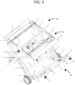
- the illustrated figures show a saw stand 100 which is configurable in a first or miter saw stand 100 configuration ( FIG. 1 ), a second or table saw configuration ( FIG. 3 ), and a third or transport configuration ( FIG. 5 ).
- FIG. 1 illustrates the saw stand 100 for tools according to an embodiment of the invention.
- the illustrated figure shows the saw stand 100 in the first configuration.
- the saw stand 100 includes a table assembly 50 with first 55 and second 56 side rails and one or more cross rails 51 extending between the side rails 55, 56.
- the cross rails 51 are positioned perpendicular, i.e 90 degrees, with respect to the side rails 55, 56.
- the side rails 51 may have slots 52 extending in the longitude of the side rails 55, 56 for retaining another rail 54, or rails, i.e implementing rails.
- the implementing rails 54 can be fixed to the slots 52 of the side rails via screws 53.
- the implementing rails 54 could be slid along the slots of the side rails 55, 56. After a suitable position is determined, the screws 53 can be tightened, and the tool can be secured to the saw stand 100.
- a tabletop (not shown) including a generally planar saw support surface particularly sized and shaped for supporting a stationary tool thereon is fixed to the side rails 55, 56 and the cross rails 51.
- Types of stationary tools that can be used are, for instance, table saw, miter saw or like.
- the use of the stand is not limited hereto and any tool which could has a suitable surface could be placed on the table assembly.
- the table assembly is not so limited in use, however, and may also or alternatively be configured to support other types of tools, workpieces, and the like.
- the tabletop may be omitted, and the support surface may be collectively defined by the top sides of the side rails and cross rails.
- the saw stand 100 includes a plurality of legs 10, 20, 30, 40.
- first 10, second 20, third 30, and fourth 40 legs wherein each of the plurality of legs 10, 20, 30, 40 are pivotally coupled to one of the side rails 55, 56.
- first leg 10 and third leg 30 are pivotally coupled to the first side rail 55 and the second 20 and fourth 40 are pivotally coupled to the second side rail 56.
- the first 10 and second 20 legs are pivotable relative to the table assembly 50 about a first axis
- the third 30 and fourth 40 legs are pivotable relative to the table assembly 50 about a second axis that is parallel to the first axis.
- a handle portion spans between the distal (relative to the table assembly 50) ends of the first 10 and second 20 legs, such that the legs 10, 20 and the handle portion 64 collectively form a U-shape.
- the handle portion may be connected to each first and second leg 10, 20 via curved leg transition members 49.
- the handle portion 64 can be grasped by a user to tilt the saw stand 100 and maneuver the saw stand 100 on wheels.
- the handle portion 64 has a cylindrical member, handle member 64, wrapping around the handle portion 64 in order to utilize for ergonomic use for the user dragging the saw stand 100.
- the cylindrical member may be made of plastic material. Although a cylindrical member is given as example, other shapes and sizes are possible to facilitate the ergonomic handling of the saw stand 100.
- a base frame 60 is coupled to the distal ends of the third 30 and fourth 40 legs via curved transition members 45.
- the base frame 60 includes first 68 and second 69 frame members and a connecting frame member 63 that spans between the first and second frame members 68, 69, such that the frame members 68, 69 and the connecting frame member 63 collectively form a U-shape.
- the first frame member 68 can be connected to the connecting frame member by a curved transition frame member 48.
- the second connecting frame member 69 can be connected to the other end of the connecting frame member 63 via another curved transition frame member 48.
- a reinforcing member 67 might extend at the joining part of the third 30 and fourth 40 leg which each joins a respective curved transition member 45.
- the stand 100 further may include a cross member 43 extending between the third and fourth legs 30, 40.
- the cross member 43 is placed proximate to thirds three-thirds of the longitude of the third and fourth legs 30, 40 and is parallel to the base frame 60.
- the cross member 43 can be utilized as to provide a locking mechanism 62 for changing the configuration of the saw stand 100.
- the locking mechanism 62 provides stability when the saw stand 100 is configured in other configurations. Further details of the locking mechanism 62 will be described below.
- a pair of wheels 61 for facilitating movement of the saw stand may be coupled to the base frame 60 or proximate to the distal ends of the third and fourth legs 30, 40.
- height adjustable feet 65 are placed in order to level the saw stand 100.
- the wheels 61 are directly coupled to the transition members 45 and are thus coupled to the base frame 60 and the legs 30, 40 via the transition members 45.
- the wheels 61 may be directly coupled to the base frame 60 or to the legs 30, 40.
- the wheels 61 may facilitate moving the saw stand 100 but may be omitted in other embodiments.
- each of the legs 10, 20, 30, 40 extends straight down from the table assembly 50 to the base frame 60, such that the legs 10, 20, 30, 40 extend perpendicular to both the saw support surface and the base frame 60.
- the base frame 60 and the wheels 61 rest on the ground to support the saw stand 100.
- the connecting frame member 63 includes a first plurality of clips 66 that receive the connecting frame member 70 to retain the connecting member and the first and second legs in position. This way, the saw stand 100 is in an upstanding position.
- two clips 66 are provided; however, other quantities or configurations of clips may be used.
- any other retaining members such as magnets, hook and loop bands, and the like may be used to couple the connecting frame member 63 (and thus, the first and second legs 10, 20) to the connecting frame member 63 when the saw stand 100 is in the miter saw stand 100 configuration.
- the connecting member is retained by the clips.
- the first and second legs are positioned perpendicular to both the base frame 60 and the table assembly 50. Further, the table assembly 50 and the base frame 60 are parallel to each other.
- the saw stand 100 comprises connecting members 70, or also named as a retaining element 70, which are made to receive one or more support rods 80.
- the connecting members 70 are implemented in various locations on the saw stand 100.
- FIG. 1 shows an exemplary locations of the connecting members 70.
- the connecting members 70 are placed at the corners of the base assembly 60.
- the retaining element 70 can be fixed to the various positions of the saw stand 100. In some embodiments, the retaining element 70 is fixed to the base assembly 60 whilst in other embodiments the retaining element 70 is fixed to the first and second leg 10, 20 of the saw stand 100. Furthermore, in further embodiments, a plurality of retaining elements 70 is fixed to both the base assembly 60 and the legs of the saw stand 100.
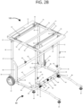
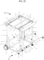
- FIGS. 2A-D show a configuration in an upstanding configuration with support rods 80 engaged to the saw stand 100.
- Two support rods 80 are engaged in the retaining elements 70 fixed to the reinforcing member 67 on one distal end and fixed to the first and second frame members 68, 69 respectively on the other distal ends.
- the retaining elements 70 can be fixed to the saw frame by welding, screwing, or like.
- FIG. 2A an embodiment where the support rods 80 engaged with the retaining elements 70 placed on the reinforcing member 67 and the curved transition frame member 48.
- the retaining element 70 is placed on the curved transition frame member 48 such that the ends are facing to the sides of the saw stand 100.
- FIG. 2B another embodiment where the supports rods 80 engaged with the retaining elements 70 placed on the curved transition frame members 48 are shown.
- the retaining elements 70 are placed on both of the curved transition frame members 48 which connects the first and second frame members 68, 69 to the connecting frame member 63.
- FIG. 2C yet another embodiment where the supports rods 80 engaged with the retaining elements 70 placed on the curved transition frame member 48 which connects the first frame member 68 to the connecting frame member 6, and the retaining element 70 which is placed on the curved transition member 45 which connects the third leg 30 to the first frame member 68.
- FIG. 2D another exemplary embodiment is shown.
- support rods 80 engaged to the retaining elements 70 placed on both of the curved transition members 45 are shown.
- the retaining element 70 is rod-shaped (not shown) which is hollow inside and is shaped to receive a distal end of the support end.
- the retaining element is L-shaped and is hollow inside and shaped to receive rod elements from each distal end of the retaining element.
- the support rods 80 are releasably fixed to the saw stand 100. Whilst in some embodiments the support rods 80 are fixed to the base assembly 60 or the plurality of legs 10, 20, 30, 40 by means of screws, in other embodiments fixation of the rod element 80 in a releasable manner is foreseen. Further details of the support rod 80 are described below.
- FIGS. 6A , 6B , 7 , 8 , 9A and 9B show the support rod 80 in detail.
- the support rod 80 further comprises one or more of leveling foot 81 for properly leveling the support rod 80.
- the leveling feet 81 have a screw-like nature.
- the foot is adjusted in height and grounded after the height of the stand 100 is set. In this manner, unwanted movement of the stand 100 can be further prevented.
- the support rod 80 can be adjusted in height to provide even distribution of weight as well as providing stability. This way, the stand 100 could be utilized even on uneven surfaces.
- the support rod 80 extends in the longitudinal direction and lays parallel to the ground.
- the support rod 80 is connected to the lower ends of the first and second legs 10, 20 by means of a push mechanism on one end.
- Another end of the rod element 80 might have the height-adjustable foot 81.
- the supporting rod comprises a first straight 82, bent portion 83 and second straight portion 84 as shown in FIGS. 6A , 6B , 7 and 8 .
- the bent portion 83 connects the first and second portions 82, 84.
- the first straight portion 82 comprises the leveling foot 81 and is positioned lower than the second straight portion 84 relative to the ground that the saw stand 100 is placed.
- the rod element 80 has an end wall portion 88 that closes the distal end of the rod element 80.
- FIG. 7 shows a support rod 180 according another embodiment of the present invention.
- the support rod 180 is U-shaped as shown and each end of the support rod 180 is fixed to a respective connecting member 70 of the saw stand 100. Similar to that of the support rod 80 as shown in FIG. 6A , the support rod 180 comprises a first straight 182, bent portion 183 and second straight portion 184.
- the first straight portion 182 comprises the leveling foot 181 and is positioned lower than the second straight portion 184 relative to the ground that the saw stand 100 is placed.
- the rod element 180 has an end wall portion 188 that closes the distal end of the rod element 180.
- the support rod 80 has a push mechanism as shown in FIGS. 9A and 9B .
- the push mechanism is placed inside the rod element 80.
- the push mechanism comprises a push button 85 that partially protrudes from a cavity 89 of the rod element 80.
- the cavity 89 is sized to receive the push button 85, preferably the cavity 89 has the exact radius as the push button 85.
- the push mechanism further comprises a flexible element (generally U-shaped), named as spring clip 86, that is engaged to a lower portion of the push button 85 which is not protruding outside.
- the spring clip 86 retains the push button 85 from moving completely out of a cavity 89 of the rod element 80.
- the other end of the spring clip 86 sits on an inner side of the support rod 80 and the tension of the spring clip 86 pushes the push button 85 out of the cavity of the rod element 80.
- the spring clip 86 may be made of a metal which provides flexibility such that when the push button 85 is pushed the spring clip 86 moves.
- a respective cavity is also present in the retaining element 70 to receive the push button 85 of the support rod 80.
- the retaining element 70 has at least one aperture 71 which is shaped exactly to receive the push mechanism of the supporting rod 80.
- the aperture 71 preferably has the same radius as the cavity 89 of the rod element 80 or the same radius as the push button 85 of the rod element 80.
- the button of the rod element 80 is pushed and slid inside the retaining element 70. Then, when the button aligns with the cavity of the retaining element the push button 85 is pushed further by the spring clip 86 and pushed partially out of the aperture 71 of the retaining element 70. This way, the supporting rod 80 is releasably secured to the saw stand 100. When removing the rod element 80 from the saw stand 100, the push button 85 is then pushed and moved out of the retaining element 70.
- the saw stand 100 can be configured in different configurations as shown in the figures.
- the saw stand 100 could be used with different types of saws or tools.
- the saw support surface is positioned at a lower height above the ground ( FIG. 3 ). In other words, the saw support surface is positioned at a lower height (i.e. closer to the ground) when the saw stand 100 is in the first (table saw) stand 100 configuration than when the saw stand 100 is in the miter saw stand 100 configuration.
- FIG. 3 illustrates the saw stand 100 in the second configuration without support rods.
- the table assembly 50 (and saw support surface) extends parallel to the ground, and each of the legs is pivoted inward and oriented at an oblique angle relative to the saw support surface.
- the first and second legs 10, 20 cross the third and fourth legs 30, 40 to generally form an X-shape.
- the wheels 61 and the handle member 64a on the handle portion 64 rest on the ground to support the saw stand 100.
- the first and second legs 10, 20 are secured to the third and fourth legs 30, 40 respectively in order to retain the saw stand 100 in the second configuration.
- a lock member which can receive the screw-like member 57 on the third and fourth legs 30, 40 in order to be engaged in the second configuration.
- the saw stand 100 is tipped over such that the table assembly 50 becomes parallel to the ground.
- the table saw stand 100 either on adjustable feet of the first and second leg 10, 20 or directly on the handle member 64a.
- any other retaining members such as magnets, hook and loop bands, and the like may be used to couple the first and second legs to the cross member when the saw stand 100 is in the table saw stand 100 configuration.
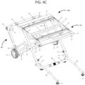
- FIGS. 4A-D illustrate the placement of support rods 80 in various location in the second configuration of the saw stand 100.
- FIG. 4A shows an embodiment where the rod elements 80 are engaged with the retaining elements 70 placed on the curved transition members 45.
- the transition members 70 in this embodiments is placed such that they are parallel to the ground, i.e. surface that the saw stand 100 is placed.
- FIG. 4B shows an embodiment where the rod elements 80 are engaged with the respective retaining elements 70 placed on the top of the curved transition member 45 which connects the third leg 30 to the first frame member 68, and the curved leg transition member 49 which connects the first leg 10 to the connecting frame member 63.
- FIG. 4C shows an embodiment where the rod elements 80 are engaged with the respective retaining elements 70 placed on the top of both curved leg transition members 49.
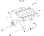
- FIG. 4D shows an embodiment where the rod elements 80 are engaged with the respective retaining elements 70 placed on the top of the curved transition member 45 which connects the fourth leg 40 to the second frame member 69, and the curved leg transition member 49 which connects the second leg 20 to the connecting frame member 63.
- a third configuration of the saw stand 100 is illustrated in FIG. 5 .
- the third configuration is used so as to store or transport the saw stand 100.
- each of the first and second legs 10, 20 is pivoted further inward until each of the legs 10, 20 extends parallel to the saw support surface and adjacent to the underside of the table.
- the legs 10, 20, 30, 40 and saw support surface are oriented perpendicular to the base frame 60.
- the first and second legs 10, 20 are pivoted inwardly till the table assembly 50 is perpendicular to the base frame 60 and that the first and second legs 10, 20 are perpendicular to the base frame 60 and parallel to the table assembly 50.
- a plurality of locking mechanisms 62 are placed on certain parts of the saw stand 100 which are to be engaged with certain parts of the saw stand 100.
- a first locking mechanism 62 is placed in a middle part of the cross member 43.
- Two other locking mechanisms 62 are placed on the first and second legs.
- the locking mechanisms 62 engage with lock receiving portion 57 placed on an underside of the table assembly 50.
- the locking mechanism 62 is shown in FIG. 10A in an unlocked position.
- a cap 161 can be turned 360 degrees and has a first engaging member 162.
- a respective second engaging member 163 is fastened to either one or more of first leg 10, second leg 20 and cross member 43 by screws 164.
- the cap 161 has a stem 168 which extends from a middle portion of the cap 161 and has a spring 165 wounding around the stem 168 which is positioned between the second engaging member and a cylindrical end 166.
- a ball end 167 is placed at the distal end of the cylindrical end 166. The ball end 167 can extend beyond a hole either one or more of first leg 10, second leg 20 and cross member 43 by screws 164.
- the spring is tensioned and the first and second engaging members 162, 163 are stacked on top of each other.
- FIG. 10B and 10C show the locking mechanism 62 in a locked position.
- the cap 161 is moved 90 degrees in its axis such that the first and second engaging members 162, 163 are integrated into each other and that the spring 165 is not tensioned.
- the ball end 167 as well as the cylindrical end 166 extends away from the hole 47 of hole either one or more of first leg 10, second leg 20 and reinforcing member 43 by screws 164.
- a user For moving and transporting the saw stand 100 in the third configuration, a user tips the entire saw stand 100 in the direction of a rotation axis of the wheels 61.
- the saw stand 100 may rotate about the wheels 61, for example, to facilitate tipping the saw stand 100.
- the handle member 64a can be grasped by the user to tilt the saw stand 100 and maneuver the saw stand 100 on the wheels 61.
Landscapes
- Engineering & Computer Science (AREA)
- Mechanical Engineering (AREA)
- Workshop Equipment, Work Benches, Supports, Or Storage Means (AREA)
- Telephone Set Structure (AREA)
- Purses, Travelling Bags, Baskets, Or Suitcases (AREA)
Abstract
Description
- The present invention relates to stands for tools, in particular, for stationary tools such as miter saws or table saws. For example, the present invention relates to foldable, movable, portable stands for tools that can be positioned in different configurations.
- Some types of saws, such as miter saws and table saws, may be supported on saw stands. Saw stands provide a support surface for supporting the saw at a convenient operating height. Some types of saw stands are designed to be transported by wheels attached to the bottom of the stand. Some types of saw stands are designed to be collapsible and transportable at the same time. Given that the saw stand is made from different parts which are not permanently fixed to each other in order to allow for a transportable and collapsible design, the table saw stands tend to not be stable when a miter saw, or table saw is in operation.
- An example of an above-described saw stand is disclosed in
EP1925406B1 . In this prior art, a foldable and movable saw stand which can be configured in three different positions is described. When the table saw is configured to be used with a miter saw or table saw, the stand does not stay stable when the miter (or table) saw is in operation by a user. With the force exerted on the saw, the saw stand tends to move in the force direction making the saw stand inconvenient for the user. - In order to address the disadvantages of stands for tools, in particular foldable tool stands, the present invention describes a solution as outlined in the independent claims.
- Accordingly, it is an object of the invention to provide a more stable stand for tools, in particular a foldable stand for stationary tools. The above-described object is achieved by a stand for tools, for example a workbench, according to
claim 1. -
-
FIG. 1 is a perspective view of a saw stand according to one embodiment of a first configuration. -
FIG. 2A is a perspective view of the saw stand according to one embodiment of the first configuration with support rods on the left side of the saw stand. -
FIG. 2B is a perspective view of the saw stand according to one embodiment of the first configuration with support rods on the front side of the saw stand. -
FIG. 2C is a perspective view of the saw stand according to one embodiment of the first configuration with support rods on the right side of the saw stand. -
FIG. 2D is a perspective view of the saw stand according to one embodiment of the first configuration with support rods on the back side of the saw stand. -
FIG. 3 is a perspective view of the saw stand according to one embodiment of a second configuration. -
FIG. 4A is a perspective view of the saw stand according to one embodiment of the second configuration with support rods on the back side of the saw stand. -
FIG. 4B is a perspective view of the saw stand according to one embodiment of the second configuration with support rods on the right side of the saw stand. -
FIG. 4C is a perspective view of the saw stand according to one embodiment of the second configuration with support rods on the front side of the saw stand. -
FIG. 4D is a perspective view of the saw stand according to one embodiment of the second configuration with support rods on the left side of the saw stand. -
FIG. 5 is a perspective view of the saw stand according to one embodiment of a third configuration. -
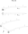
FIG. 6A shows two perspective views of the support rod from the side view. -
FIG. 6B shows two perspective views of the support rod from the side view. -
FIG. 7 is a perspective view of the support rod according to another embodiment. -
FIG. 8 is a perspective view of the support rod being engaged with a connecting member. -
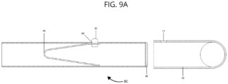
FIG. 9A is a cross-sectional side view of the support rod and the connecting member. -
FIG. 9B is another cross-sectional side view of the support rod and the connecting member. -
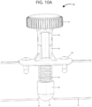
FIG. 10A is a side cross-sectional view of a locking mechanism in an open state. -
FIG. 10B is a side cross-sectional view of a locking mechanism in a closed state. -
FIG. 10C is a side view of the locking mechanism in the closed state. - The figures illustrate a stand for tools configured exemplarily as a saw stand although other types of stands could be utilized. It should be noted that the drawing figures are not intended to be limiting in scope, but rather to provide exemplary illustrations.
- The illustrated figures show a
saw stand 100 which is configurable in a first ormiter saw stand 100 configuration (FIG. 1 ), a second or table saw configuration (FIG. 3 ), and a third or transport configuration (FIG. 5 ). -
FIG. 1 illustrates thesaw stand 100 for tools according to an embodiment of the invention. The illustrated figure shows thesaw stand 100 in the first configuration. Thesaw stand 100 includes atable assembly 50 with first 55 and second 56 side rails and one ormore cross rails 51 extending between theside rails cross rails 51 are positioned perpendicular, i.e 90 degrees, with respect to theside rails side rails 51 may haveslots 52 extending in the longitude of theside rails rail 54, or rails, i.e implementing rails. The implementingrails 54 can be fixed to theslots 52 of the side rails viascrews 53. Depending on the type of tool that is going to be placed on thetable assembly 50, the implementingrails 54 could be slid along the slots of theside rails screws 53 can be tightened, and the tool can be secured to thesaw stand 100. In other words, a tabletop (not shown) including a generally planar saw support surface particularly sized and shaped for supporting a stationary tool thereon is fixed to the side rails 55, 56 and the cross rails 51. - Types of stationary tools that can be used are, for instance, table saw, miter saw or like. However, it is noted that the use of the stand is not limited hereto and any tool which could has a suitable surface could be placed on the table assembly. The table assembly is not so limited in use, however, and may also or alternatively be configured to support other types of tools, workpieces, and the like. In some embodiments, the tabletop may be omitted, and the support surface may be collectively defined by the top sides of the side rails and cross rails.
- Furthermore,
FIG. 1 , thesaw stand 100 includes a plurality oflegs legs first leg 10 andthird leg 30 are pivotally coupled to thefirst side rail 55 and the second 20 and fourth 40 are pivotally coupled to thesecond side rail 56. The first 10 and second 20 legs are pivotable relative to thetable assembly 50 about a first axis, and the third 30 and fourth 40 legs are pivotable relative to thetable assembly 50 about a second axis that is parallel to the first axis. - A handle portion spans between the distal (relative to the table assembly 50) ends of the first 10 and second 20 legs, such that the
legs handle portion 64 collectively form a U-shape. In particular, the handle portion may be connected to each first andsecond leg leg transition members 49. - The
handle portion 64 can be grasped by a user to tilt thesaw stand 100 and maneuver the saw stand 100 on wheels. Preferably, thehandle portion 64 has a cylindrical member,handle member 64, wrapping around thehandle portion 64 in order to utilize for ergonomic use for the user dragging thesaw stand 100. The cylindrical member may be made of plastic material. Although a cylindrical member is given as example, other shapes and sizes are possible to facilitate the ergonomic handling of thesaw stand 100. - A
base frame 60 is coupled to the distal ends of the third 30 and fourth 40 legs viacurved transition members 45. Thebase frame 60 includes first 68 and second 69 frame members and a connectingframe member 63 that spans between the first andsecond frame members frame members frame member 63 collectively form a U-shape. Thefirst frame member 68 can be connected to the connecting frame member by a curvedtransition frame member 48. Similarly, the second connectingframe member 69 can be connected to the other end of the connectingframe member 63 via another curvedtransition frame member 48. - In some embodiments, a reinforcing
member 67 might extend at the joining part of the third 30 and fourth 40 leg which each joins a respectivecurved transition member 45. - In the figures, the
stand 100 further may include across member 43 extending between the third andfourth legs cross member 43 is placed proximate to thirds three-thirds of the longitude of the third andfourth legs base frame 60. Furthermore, thecross member 43 can be utilized as to provide alocking mechanism 62 for changing the configuration of thesaw stand 100. Thelocking mechanism 62 provides stability when thesaw stand 100 is configured in other configurations. Further details of thelocking mechanism 62 will be described below. - A pair of
wheels 61 for facilitating movement of the saw stand may be coupled to thebase frame 60 or proximate to the distal ends of the third andfourth legs base frame 60 facing the wheels, heightadjustable feet 65 are placed in order to level thesaw stand 100. In the illustrated embodiment, thewheels 61 are directly coupled to thetransition members 45 and are thus coupled to thebase frame 60 and thelegs transition members 45. In other embodiments, thewheels 61 may be directly coupled to thebase frame 60 or to thelegs wheels 61 may facilitate moving the saw stand 100 but may be omitted in other embodiments. - In the first configuration as shown in
FIG. 1 , each of thelegs table assembly 50 to thebase frame 60, such that thelegs base frame 60. Thebase frame 60 and thewheels 61 rest on the ground to support thesaw stand 100. - The connecting
frame member 63 includes a first plurality ofclips 66 that receive the connectingframe member 70 to retain the connecting member and the first and second legs in position. This way, thesaw stand 100 is in an upstanding position. In the illustrated embodiment, twoclips 66 are provided; however, other quantities or configurations of clips may be used. Alternatively, any other retaining members, such as magnets, hook and loop bands, and the like may be used to couple the connecting frame member 63 (and thus, the first andsecond legs 10, 20) to the connectingframe member 63 when thesaw stand 100 is in the miter sawstand 100 configuration. - In the first configuration of the
saw stand 100, the connecting member is retained by the clips. In this way, the first and second legs are positioned perpendicular to both thebase frame 60 and thetable assembly 50. Further, thetable assembly 50 and thebase frame 60 are parallel to each other. - Furthermore, the
saw stand 100 comprises connectingmembers 70, or also named as a retainingelement 70, which are made to receive one ormore support rods 80. As is seen inFIG. 1 , the connectingmembers 70 are implemented in various locations on thesaw stand 100.FIG. 1 shows an exemplary locations of the connectingmembers 70. For instance, the connectingmembers 70 are placed at the corners of thebase assembly 60. - The retaining
element 70 can be fixed to the various positions of thesaw stand 100. In some embodiments, the retainingelement 70 is fixed to thebase assembly 60 whilst in other embodiments the retainingelement 70 is fixed to the first andsecond leg saw stand 100. Furthermore, in further embodiments, a plurality of retainingelements 70 is fixed to both thebase assembly 60 and the legs of thesaw stand 100. - In
FIGS. 2A-D show a configuration in an upstanding configuration withsupport rods 80 engaged to thesaw stand 100. - Two
support rods 80 are engaged in the retainingelements 70 fixed to the reinforcingmember 67 on one distal end and fixed to the first andsecond frame members elements 70 can be fixed to the saw frame by welding, screwing, or like. - In
FIG. 2A , an embodiment where thesupport rods 80 engaged with the retainingelements 70 placed on the reinforcingmember 67 and the curvedtransition frame member 48. The retainingelement 70 is placed on the curvedtransition frame member 48 such that the ends are facing to the sides of thesaw stand 100. - In
FIG. 2B , another embodiment where thesupports rods 80 engaged with the retainingelements 70 placed on the curvedtransition frame members 48 are shown. In particular, the retainingelements 70 are placed on both of the curvedtransition frame members 48 which connects the first andsecond frame members frame member 63. - In
Fig. 2C , yet another embodiment where thesupports rods 80 engaged with the retainingelements 70 placed on the curvedtransition frame member 48 which connects thefirst frame member 68 to the connecting frame member 6, and the retainingelement 70 which is placed on thecurved transition member 45 which connects thethird leg 30 to thefirst frame member 68. - In
FIG. 2D , another exemplary embodiment is shown. In particular,support rods 80 engaged to the retainingelements 70 placed on both of thecurved transition members 45 are shown. - In some embodiments, the retaining
element 70 is rod-shaped (not shown) which is hollow inside and is shaped to receive a distal end of the support end. In other embodiments, the retaining element is L-shaped and is hollow inside and shaped to receive rod elements from each distal end of the retaining element. - For providing further stability to the
stand 100, thesupport rods 80 are releasably fixed to thesaw stand 100. Whilst in some embodiments thesupport rods 80 are fixed to thebase assembly 60 or the plurality oflegs rod element 80 in a releasable manner is foreseen. Further details of thesupport rod 80 are described below. -
FIGS. 6A ,6B ,7 ,8 ,9A and9B show thesupport rod 80 in detail. Thesupport rod 80 further comprises one or more of levelingfoot 81 for properly leveling thesupport rod 80. The levelingfeet 81 have a screw-like nature. In the use of thestand 100, for cutting a workpiece, for example, the foot is adjusted in height and grounded after the height of thestand 100 is set. In this manner, unwanted movement of thestand 100 can be further prevented. Additionally, if thestand 100 is placed on uneven surfaces, thesupport rod 80 can be adjusted in height to provide even distribution of weight as well as providing stability. This way, thestand 100 could be utilized even on uneven surfaces. - The
support rod 80 extends in the longitudinal direction and lays parallel to the ground. Thesupport rod 80 is connected to the lower ends of the first andsecond legs rod element 80 might have the height-adjustable foot 81. - In some embodiments, the supporting rod comprises a first straight 82,
bent portion 83 and secondstraight portion 84 as shown inFIGS. 6A ,6B ,7 and8 . Thebent portion 83 connects the first andsecond portions straight portion 82 comprises the levelingfoot 81 and is positioned lower than the secondstraight portion 84 relative to the ground that thesaw stand 100 is placed. - The
rod element 80 has anend wall portion 88 that closes the distal end of therod element 80. -
FIG. 7 shows asupport rod 180 according another embodiment of the present invention. In this embodiment, thesupport rod 180 is U-shaped as shown and each end of thesupport rod 180 is fixed to a respective connectingmember 70 of thesaw stand 100. Similar to that of thesupport rod 80 as shown inFIG. 6A , thesupport rod 180 comprises a first straight 182,bent portion 183 and secondstraight portion 184. The firststraight portion 182 comprises the levelingfoot 181 and is positioned lower than the secondstraight portion 184 relative to the ground that thesaw stand 100 is placed. Therod element 180 has anend wall portion 188 that closes the distal end of therod element 180. - Furthermore, the
support rod 80 has a push mechanism as shown inFIGS. 9A and9B . The push mechanism is placed inside therod element 80. In particular, the push mechanism comprises apush button 85 that partially protrudes from acavity 89 of therod element 80. Thecavity 89 is sized to receive thepush button 85, preferably thecavity 89 has the exact radius as thepush button 85. The push mechanism further comprises a flexible element (generally U-shaped), named asspring clip 86, that is engaged to a lower portion of thepush button 85 which is not protruding outside. Thespring clip 86 retains thepush button 85 from moving completely out of acavity 89 of therod element 80. The other end of thespring clip 86 sits on an inner side of thesupport rod 80 and the tension of thespring clip 86 pushes thepush button 85 out of the cavity of therod element 80. Thespring clip 86 may be made of a metal which provides flexibility such that when thepush button 85 is pushed thespring clip 86 moves. - As shown in
FIGS. 9A and9B , a respective cavity is also present in the retainingelement 70 to receive thepush button 85 of thesupport rod 80. The retainingelement 70 has at least oneaperture 71 which is shaped exactly to receive the push mechanism of the supportingrod 80. Theaperture 71 preferably has the same radius as thecavity 89 of therod element 80 or the same radius as thepush button 85 of therod element 80. - When assembling the supporting
rod 80 to thesaw stand 100, the button of therod element 80 is pushed and slid inside the retainingelement 70. Then, when the button aligns with the cavity of the retaining element thepush button 85 is pushed further by thespring clip 86 and pushed partially out of theaperture 71 of the retainingelement 70. This way, the supportingrod 80 is releasably secured to thesaw stand 100. When removing therod element 80 from thesaw stand 100, thepush button 85 is then pushed and moved out of the retainingelement 70. - The saw stand 100 can be configured in different configurations as shown in the figures. In the second configuration of the
saw stand 100, thesaw stand 100 could be used with different types of saws or tools. In the second (table saw stand 100) configuration, the saw support surface is positioned at a lower height above the ground (FIG. 3 ). In other words, the saw support surface is positioned at a lower height (i.e. closer to the ground) when thesaw stand 100 is in the first (table saw) stand 100 configuration than when thesaw stand 100 is in the miter sawstand 100 configuration. -
FIG. 3 illustrates thesaw stand 100 in the second configuration without support rods. The table assembly 50 (and saw support surface) extends parallel to the ground, and each of the legs is pivoted inward and oriented at an oblique angle relative to the saw support surface. The first andsecond legs fourth legs wheels 61 and thehandle member 64a on thehandle portion 64 rest on the ground to support thesaw stand 100. - The first and
second legs fourth legs saw stand 100 in the second configuration. - In the middle portion of both the first and
second leg like member 57 on the third andfourth legs saw stand 100 is tipped over such that thetable assembly 50 becomes parallel to the ground. In the second configuration, the table saw stand 100 either on adjustable feet of the first andsecond leg handle member 64a. - In other embodiments, other quantities or configurations of clips may be used. Alternatively, any other retaining members, such as magnets, hook and loop bands, and the like may be used to couple the first and second legs to the cross member when the
saw stand 100 is in the table saw stand 100 configuration. -
FIGS. 4A-D illustrate the placement ofsupport rods 80 in various location in the second configuration of thesaw stand 100. -
FIG. 4A shows an embodiment where therod elements 80 are engaged with the retainingelements 70 placed on thecurved transition members 45. Thetransition members 70 in this embodiments is placed such that they are parallel to the ground, i.e. surface that thesaw stand 100 is placed. -
FIG. 4B shows an embodiment where therod elements 80 are engaged with therespective retaining elements 70 placed on the top of thecurved transition member 45 which connects thethird leg 30 to thefirst frame member 68, and the curvedleg transition member 49 which connects thefirst leg 10 to the connectingframe member 63. -
FIG. 4C shows an embodiment where therod elements 80 are engaged with therespective retaining elements 70 placed on the top of both curvedleg transition members 49. -
FIG. 4D shows an embodiment where therod elements 80 are engaged with therespective retaining elements 70 placed on the top of thecurved transition member 45 which connects thefourth leg 40 to thesecond frame member 69, and the curvedleg transition member 49 which connects thesecond leg 20 to the connectingframe member 63. - A third configuration of the
saw stand 100 is illustrated inFIG. 5 . The third configuration is used so as to store or transport thesaw stand 100. In order to configure thesaw stand 100 in the third configuration, each of the first andsecond legs legs legs base frame 60. - In order to configure the
saw stand 100 in the third configuration, the first andsecond legs table assembly 50 is perpendicular to thebase frame 60 and that the first andsecond legs base frame 60 and parallel to thetable assembly 50. - In order to secure the
saw stand 100, a plurality of lockingmechanisms 62 are placed on certain parts of the saw stand 100 which are to be engaged with certain parts of thesaw stand 100. For instance, afirst locking mechanism 62 is placed in a middle part of thecross member 43. Two other lockingmechanisms 62 are placed on the first and second legs. The lockingmechanisms 62 engage withlock receiving portion 57 placed on an underside of thetable assembly 50. - The
locking mechanism 62 is shown inFIG. 10A in an unlocked position. Acap 161 can be turned 360 degrees and has a first engagingmember 162. A respective second engagingmember 163 is fastened to either one or more offirst leg 10,second leg 20 andcross member 43 byscrews 164. Thecap 161 has astem 168 which extends from a middle portion of thecap 161 and has aspring 165 wounding around thestem 168 which is positioned between the second engaging member and acylindrical end 166. Aball end 167 is placed at the distal end of thecylindrical end 166. Theball end 167 can extend beyond a hole either one or more offirst leg 10,second leg 20 andcross member 43 byscrews 164. In the unlocked position, the spring is tensioned and the first and second engagingmembers -
FIG. 10B and10C show thelocking mechanism 62 in a locked position. Thecap 161 is moved 90 degrees in its axis such that the first and second engagingmembers spring 165 is not tensioned. In this position, the ball end 167 as well as thecylindrical end 166 extends away from thehole 47 of hole either one or more offirst leg 10,second leg 20 and reinforcingmember 43 byscrews 164. - For moving and transporting the
saw stand 100 in the third configuration, a user tips theentire saw stand 100 in the direction of a rotation axis of thewheels 61. The saw stand 100 may rotate about thewheels 61, for example, to facilitate tipping thesaw stand 100. Thehandle member 64a can be grasped by the user to tilt thesaw stand 100 and maneuver the saw stand 100 on thewheels 61. - Although particularly preferred embodiments of the invention have been disclosed in detail for illustrative purposes to demonstrate the improvement over known constructions, it will be recognized that variations or modifications of the disclosed apparatus of the invention, including the rearrangement of parts, lie within the scope of the present invention.
10 1st leg 71 aperture 12 reinforcing member 72 interior wall surface 13 adjustable foot of the legs 80 support rod/ rod element 14 lock member 81 adjustable foot (rod element) / 20 2nd leg leveling foot 30 3rd leg 82 1st portion 40 4th leg 83 bent portion/ inclined transition 43 cross member surface 45 curved transition member 84 2nd portion 46 support panel 85 push button 47 hole 86 spring clip 48 curved transition frame member 87 outer periphery 49 curved leg transition member 88 end wall portion 50 table assembly 89 cavity 51 cross rail 100 saw stand 52 side rail slot 161 cap 53 screw 162 1st engaging member 54 implementing rails 163 2nd engaging member 55 1st side rail 164 screw 56 2nd side rail 165 spring 57 lock receiving portion 166 cylindrical end 60 base frame 167 ball end 61 wheel 180 rod element 62 locking mechanism 181 adjustable foot (rod element) 63 connecting frame member 182 1st portion 64 handle portion 183 bent portion/ inclined transition 64a handle member surface 65 adjustable foot of the base frame 184 2nd portion 66 clip 185 push button 67 reinforcing member (base frame) 186 spring clip 68 first frame member 187 outer periphery 69 second frame member 188 end wall portion 70 connecting member/ retaining element
Claims (14)
- A stand for tools comprising:a table assembly providing a support surface for the tool to be placed;a plurality of legs having first ends coupled to the table assembly; anda base frame coupled to second ends of the plurality of legs,characterized in that the stand further comprises a support rod releasably coupled to the base frame and/or one or more of the plurality of legs.
- The stand for tools of claim 1, wherein the support rod is releasably attached to the base frame by a retaining element.
- The stand for tools according to claim 2, wherein the retaining element is hollow inside and is made to receive the distal end of the support rod.
- The stand for tools according to one of the preceding claims, wherein the support rod is tubular and preferably U-shaped.
- The stand for tools according to one of claims 1 or 4, wherein the support rod is releasably coupled to the base frame and/or one or more of the plurality of legs by a retaining element via a snap-fitting element.
- The stand for tools according to one of the preceding claims, wherein the plurality of legs are pivotably attached to the table assembly.
- The stand for tools according to one of the preceding claims, wherein the support rod rests on the ground where the stand is placed and the support rod extends parallel to the ground.
- The stand for tools according to claim 2, wherein at least two support rods are engaged in the retaining elements fixed to the reinforcing member on one distal end and fixed to the first and second frame members respectively on the other distal ends.
- The stand for tools according to claim 8, wherein the retaining elements are fixed to the saw frame by welding, screwing, or like.
- The stand for tools according to claim 1, wherein the support rod comprises a first straight portion, a bent portion and second straight portion, wherein the bent portion connects the first and second portions.
- The stand for tools according to claim 10, wherein the first straight portion comprises a leveling foot and is positioned lower than the second straight portion relative to the ground that the saw stand is placed.
- The stand for tools according to claim 1, wherein the support rod has a push mechanism placed inside the rod element and wherein the push mechanism comprises a push button that partially protrudes from a cavity of the rod element.
- The stand for tools according to claim 12, wherein the push mechanism further comprises a flexible element, preferably U-shaped, that is engaged to a lower portion of the push button which is not protruding outside, and wherein a flexible element retains the push button from moving completely out of a cavity of the rod element.
- The stand for tools according to claim 13, wherein a respective cavity is present in the retaining element (70) to receive the push button (85) of the support rod and wherein when assembling the supporting rod to the stand, the button of the rod element is pushed and slid inside the retaining element.
Priority Applications (1)
| Application Number | Priority Date | Filing Date | Title |
|---|---|---|---|
| EP23155703.4A EP4414138B1 (en) | 2023-02-09 | 2023-02-09 | Stand for tools with support structure |
Applications Claiming Priority (1)
| Application Number | Priority Date | Filing Date | Title |
|---|---|---|---|
| EP23155703.4A EP4414138B1 (en) | 2023-02-09 | 2023-02-09 | Stand for tools with support structure |
Publications (4)
| Publication Number | Publication Date |
|---|---|
| EP4414138A1 true EP4414138A1 (en) | 2024-08-14 |
| EP4414138A8 EP4414138A8 (en) | 2024-09-25 |
| EP4414138B1 EP4414138B1 (en) | 2025-12-17 |
| EP4414138C0 EP4414138C0 (en) | 2025-12-17 |
Family
ID=85221863
Family Applications (1)
| Application Number | Title | Priority Date | Filing Date |
|---|---|---|---|
| EP23155703.4A Active EP4414138B1 (en) | 2023-02-09 | 2023-02-09 | Stand for tools with support structure |
Country Status (1)
| Country | Link |
|---|---|
| EP (1) | EP4414138B1 (en) |
Citations (6)
| Publication number | Priority date | Publication date | Assignee | Title |
|---|---|---|---|---|
| US20050034783A1 (en) * | 2003-08-11 | 2005-02-17 | Laird R. Wayne | Portable, dual-station, expandable carpenter's work bench |
| US20080203704A1 (en) * | 2007-02-27 | 2008-08-28 | Mccracken Robert E | Foldable stand for supporting a power tool |
| EP1925406B1 (en) | 2006-11-21 | 2009-07-01 | Makita Corporation | Workbench for power tool |
| US20090174162A1 (en) * | 2007-12-21 | 2009-07-09 | Gass Stephen F | Mobile base for a table saw |
| US7648155B1 (en) * | 2000-03-02 | 2010-01-19 | Wise Robert W | Universal mobile saw stand |
| EP2335883A2 (en) * | 2009-12-16 | 2011-06-22 | Festool GmbH | Frame for transporting a machine tool |
-
2023
- 2023-02-09 EP EP23155703.4A patent/EP4414138B1/en active Active
Patent Citations (6)
| Publication number | Priority date | Publication date | Assignee | Title |
|---|---|---|---|---|
| US7648155B1 (en) * | 2000-03-02 | 2010-01-19 | Wise Robert W | Universal mobile saw stand |
| US20050034783A1 (en) * | 2003-08-11 | 2005-02-17 | Laird R. Wayne | Portable, dual-station, expandable carpenter's work bench |
| EP1925406B1 (en) | 2006-11-21 | 2009-07-01 | Makita Corporation | Workbench for power tool |
| US20080203704A1 (en) * | 2007-02-27 | 2008-08-28 | Mccracken Robert E | Foldable stand for supporting a power tool |
| US20090174162A1 (en) * | 2007-12-21 | 2009-07-09 | Gass Stephen F | Mobile base for a table saw |
| EP2335883A2 (en) * | 2009-12-16 | 2011-06-22 | Festool GmbH | Frame for transporting a machine tool |
Also Published As
| Publication number | Publication date |
|---|---|
| EP4414138B1 (en) | 2025-12-17 |
| EP4414138C0 (en) | 2025-12-17 |
| EP4414138A8 (en) | 2024-09-25 |
Similar Documents
| Publication | Publication Date | Title |
|---|---|---|
| US6845991B1 (en) | Folding wagon/cart | |
| US9131779B2 (en) | Foldable bed frame | |
| US6912961B2 (en) | Personal table | |
| US4715488A (en) | Collapsible conveyor | |
| US6010186A (en) | Combination desk and chair | |
| US9468297B2 (en) | Slim fold cross brace design | |
| US5320150A (en) | Collapsible stand | |
| US5037117A (en) | Folding table caddie | |
| JP3948695B2 (en) | Goods transportation storage device | |
| US5642895A (en) | Convertible work bench to hand truck apparatus | |
| US20050133682A1 (en) | Folding collapsible stand for table saw | |
| US4691885A (en) | Display stand | |
| US4951782A (en) | Foldable sawhorse | |
| US10813446B2 (en) | Collapsible infeed/outfeed table with shelf | |
| US2706609A (en) | Pedestal-type supporting stand having foldable base legs | |
| US5184697A (en) | Locking swivel for rotatably connecting two components | |
| US4854531A (en) | Three legged workbench | |
| EP4414138B1 (en) | Stand for tools with support structure | |
| US6151816A (en) | Portable quilting frame assembly | |
| US4883246A (en) | Three legged workbench | |
| US8191906B2 (en) | Modular utility stand storage apparatus and method | |
| US11129469B2 (en) | Collapsible brace member for a furniture support structure | |
| US20050217541A1 (en) | Stanchion support | |
| US7128001B2 (en) | Foldable table | |
| AU2003273580B2 (en) | Personal table |
Legal Events
| Date | Code | Title | Description |
|---|---|---|---|
| PUAI | Public reference made under article 153(3) epc to a published international application that has entered the european phase |
Free format text: ORIGINAL CODE: 0009012 |
|
| STAA | Information on the status of an ep patent application or granted ep patent |
Free format text: STATUS: THE APPLICATION HAS BEEN PUBLISHED |
|
| AK | Designated contracting states |
Kind code of ref document: A1 Designated state(s): AL AT BE BG CH CY CZ DE DK EE ES FI FR GB GR HR HU IE IS IT LI LT LU LV MC ME MK MT NL NO PL PT RO RS SE SI SK SM TR |
|
| RIN1 | Information on inventor provided before grant (corrected) |
Inventor name: SCHIEWIETZ, GUENTER |
|
| STAA | Information on the status of an ep patent application or granted ep patent |
Free format text: STATUS: REQUEST FOR EXAMINATION WAS MADE |
|
| 17P | Request for examination filed |
Effective date: 20250204 |
|
| GRAJ | Information related to disapproval of communication of intention to grant by the applicant or resumption of examination proceedings by the epo deleted |
Free format text: ORIGINAL CODE: EPIDOSDIGR1 |
|
| GRAP | Despatch of communication of intention to grant a patent |
Free format text: ORIGINAL CODE: EPIDOSNIGR1 |
|
| GRAP | Despatch of communication of intention to grant a patent |
Free format text: ORIGINAL CODE: EPIDOSNIGR1 |
|
| STAA | Information on the status of an ep patent application or granted ep patent |
Free format text: STATUS: GRANT OF PATENT IS INTENDED |
|
| INTG | Intention to grant announced |
Effective date: 20250718 |
|
| GRAS | Grant fee paid |
Free format text: ORIGINAL CODE: EPIDOSNIGR3 |
|
| GRAA | (expected) grant |
Free format text: ORIGINAL CODE: 0009210 |
|
| STAA | Information on the status of an ep patent application or granted ep patent |
Free format text: STATUS: THE PATENT HAS BEEN GRANTED |
|
| AK | Designated contracting states |
Kind code of ref document: B1 Designated state(s): AL AT BE BG CH CY CZ DE DK EE ES FI FR GB GR HR HU IE IS IT LI LT LU LV MC ME MK MT NL NO PL PT RO RS SE SI SK SM TR |
|
| REG | Reference to a national code |
Ref country code: CH Ref legal event code: F10 Free format text: ST27 STATUS EVENT CODE: U-0-0-F10-F00 (AS PROVIDED BY THE NATIONAL OFFICE) Effective date: 20251217 Ref country code: GB Ref legal event code: FG4D |
|
| REG | Reference to a national code |
Ref country code: DE Ref legal event code: R096 Ref document number: 602023009676 Country of ref document: DE |
|
| U01 | Request for unitary effect filed |
Effective date: 20260105 |
|
| U07 | Unitary effect registered |
Designated state(s): AT BE BG DE DK EE FI FR IT LT LU LV MT NL PT RO SE SI Effective date: 20260113 |
|
| U20 | Renewal fee for the european patent with unitary effect paid |
Year of fee payment: 4 Effective date: 20260225 |
|
| PG25 | Lapsed in a contracting state [announced via postgrant information from national office to epo] |
Ref country code: NO Free format text: LAPSE BECAUSE OF FAILURE TO SUBMIT A TRANSLATION OF THE DESCRIPTION OR TO PAY THE FEE WITHIN THE PRESCRIBED TIME-LIMIT Effective date: 20260317 |
|
| PG25 | Lapsed in a contracting state [announced via postgrant information from national office to epo] |
Ref country code: HR Free format text: LAPSE BECAUSE OF FAILURE TO SUBMIT A TRANSLATION OF THE DESCRIPTION OR TO PAY THE FEE WITHIN THE PRESCRIBED TIME-LIMIT Effective date: 20251217 |
|
| PG25 | Lapsed in a contracting state [announced via postgrant information from national office to epo] |
Ref country code: RS Free format text: LAPSE BECAUSE OF FAILURE TO SUBMIT A TRANSLATION OF THE DESCRIPTION OR TO PAY THE FEE WITHIN THE PRESCRIBED TIME-LIMIT Effective date: 20260317 |