EP4414098A1 - Manufacturing method for a plate laminate unit for a heat exchanger - Google Patents
Manufacturing method for a plate laminate unit for a heat exchanger Download PDFInfo
- Publication number
- EP4414098A1 EP4414098A1 EP22901212.5A EP22901212A EP4414098A1 EP 4414098 A1 EP4414098 A1 EP 4414098A1 EP 22901212 A EP22901212 A EP 22901212A EP 4414098 A1 EP4414098 A1 EP 4414098A1
- Authority
- EP
- European Patent Office
- Prior art keywords
- plate laminate
- pair
- plates
- laminating direction
- heat exchanger
- Prior art date
- Legal status (The legal status is an assumption and is not a legal conclusion. Google has not performed a legal analysis and makes no representation as to the accuracy of the status listed.)
- Granted
Links
Images


Classifications
-
- B—PERFORMING OPERATIONS; TRANSPORTING
- B21—MECHANICAL METAL-WORKING WITHOUT ESSENTIALLY REMOVING MATERIAL; PUNCHING METAL
- B21D—WORKING OR PROCESSING OF SHEET METAL OR METAL TUBES, RODS OR PROFILES WITHOUT ESSENTIALLY REMOVING MATERIAL; PUNCHING METAL
- B21D53/00—Making other particular articles
- B21D53/02—Making other particular articles heat exchangers or parts thereof, e.g. radiators, condensers fins, headers
- B21D53/04—Making other particular articles heat exchangers or parts thereof, e.g. radiators, condensers fins, headers of sheet metal
-
- F—MECHANICAL ENGINEERING; LIGHTING; HEATING; WEAPONS; BLASTING
- F28—HEAT EXCHANGE IN GENERAL
- F28F—DETAILS OF HEAT-EXCHANGE AND HEAT-TRANSFER APPARATUS, OF GENERAL APPLICATION
- F28F3/00—Plate-like or laminated elements; Assemblies of plate-like or laminated elements
- F28F3/08—Elements constructed for building-up into stacks, e.g. capable of being taken apart for cleaning
-
- B—PERFORMING OPERATIONS; TRANSPORTING
- B21—MECHANICAL METAL-WORKING WITHOUT ESSENTIALLY REMOVING MATERIAL; PUNCHING METAL
- B21D—WORKING OR PROCESSING OF SHEET METAL OR METAL TUBES, RODS OR PROFILES WITHOUT ESSENTIALLY REMOVING MATERIAL; PUNCHING METAL
- B21D39/00—Application of procedures in order to connect objects or parts, e.g. coating with sheet metal otherwise than by plating; Tube expanders
- B21D39/02—Application of procedures in order to connect objects or parts, e.g. coating with sheet metal otherwise than by plating; Tube expanders of sheet metal by folding, e.g. connecting edges of a sheet to form a cylinder
- B21D39/028—Reinforcing the connection otherwise than by deforming, e.g. welding
-
- B—PERFORMING OPERATIONS; TRANSPORTING
- B23—MACHINE TOOLS; METAL-WORKING NOT OTHERWISE PROVIDED FOR
- B23K—SOLDERING OR UNSOLDERING; WELDING; CLADDING OR PLATING BY SOLDERING OR WELDING; CUTTING BY APPLYING HEAT LOCALLY, e.g. FLAME CUTTING; WORKING BY LASER BEAM
- B23K37/00—Auxiliary devices or processes, not specially adapted for a procedure covered by only one of the other main groups of this subclass
- B23K37/04—Auxiliary devices or processes, not specially adapted for a procedure covered by only one of the other main groups of this subclass for holding or positioning work
-
- B—PERFORMING OPERATIONS; TRANSPORTING
- B23—MACHINE TOOLS; METAL-WORKING NOT OTHERWISE PROVIDED FOR
- B23P—METAL-WORKING NOT OTHERWISE PROVIDED FOR; COMBINED OPERATIONS; UNIVERSAL MACHINE TOOLS
- B23P15/00—Making specific metal objects by operations not covered by a single other subclass or a group in this subclass
- B23P15/26—Making specific metal objects by operations not covered by a single other subclass or a group in this subclass heat exchangers or the like
-
- F—MECHANICAL ENGINEERING; LIGHTING; HEATING; WEAPONS; BLASTING
- F28—HEAT EXCHANGE IN GENERAL
- F28F—DETAILS OF HEAT-EXCHANGE AND HEAT-TRANSFER APPARATUS, OF GENERAL APPLICATION
- F28F3/00—Plate-like or laminated elements; Assemblies of plate-like or laminated elements
- F28F3/02—Elements or assemblies thereof with means for increasing heat-transfer area, e.g. with fins, with recesses, with corrugations
- F28F3/04—Elements or assemblies thereof with means for increasing heat-transfer area, e.g. with fins, with recesses, with corrugations the means being integral with the element
-
- F—MECHANICAL ENGINEERING; LIGHTING; HEATING; WEAPONS; BLASTING
- F28—HEAT EXCHANGE IN GENERAL
- F28F—DETAILS OF HEAT-EXCHANGE AND HEAT-TRANSFER APPARATUS, OF GENERAL APPLICATION
- F28F3/00—Plate-like or laminated elements; Assemblies of plate-like or laminated elements
- F28F3/08—Elements constructed for building-up into stacks, e.g. capable of being taken apart for cleaning
- F28F3/10—Arrangements for sealing the margins
-
- B—PERFORMING OPERATIONS; TRANSPORTING
- B23—MACHINE TOOLS; METAL-WORKING NOT OTHERWISE PROVIDED FOR
- B23P—METAL-WORKING NOT OTHERWISE PROVIDED FOR; COMBINED OPERATIONS; UNIVERSAL MACHINE TOOLS
- B23P2700/00—Indexing scheme relating to the articles being treated, e.g. manufactured, repaired, assembled, connected or other operations covered in the subgroups
- B23P2700/12—Laminated parts
-
- F—MECHANICAL ENGINEERING; LIGHTING; HEATING; WEAPONS; BLASTING
- F28—HEAT EXCHANGE IN GENERAL
- F28F—DETAILS OF HEAT-EXCHANGE AND HEAT-TRANSFER APPARATUS, OF GENERAL APPLICATION
- F28F2255/00—Heat exchanger elements made of materials having special features or resulting from particular manufacturing processes
- F28F2255/08—Heat exchanger elements made of materials having special features or resulting from particular manufacturing processes pressed; stamped; deep-drawn
Definitions
- the present disclosure relates to a method of producing a plate laminate unit for a heat exchanger.
- the heat exchanger disclosed in Patent Document 1 contains a plate laminate configured to exchange heat between CO 2 refrigerant and NH 3 refrigerant.
- the plate laminate includes a plurality of plates welded together and a pair of terminal plates that sandwiches the plurality of plates from both sides in the laminating direction.
- One of the pairs of terminal plates illustrated in this document closes the flow path for the CO 2 refrigerant.
- the other terminal plate has an inlet tube and an outlet tube. Both the inlet and outlet tubes communicate with the CO 2 refrigerant path formed in the plate laminate.
- Patent Document 1 JP5690532B
- Patent Document 1 does not disclose any specific method for proper welding.
- An object of the present disclosure is to provide a method of producing a plate laminate unit for a heat exchanger whereby it is possible to properly weld a pair of terminal plates and a plate laminate.
- a method of producing a plate laminate unit for a heat exchanger includes: a compressing step of compressing a plate laminate, a pair of terminal plates disposed on both sides of the plate laminate in a laminating direction, and a pair of binding plates disposed on both sides of the pair of terminal plates in the laminating direction, using a pressing tool from both sides in the laminating direction; a welding step of welding an edge portion of the plate laminate to edge portions of the pair of terminal plates during the compressing step; a connecting step of connecting the pair of binding plates to each other by a connector after the welding step; and a pressure-releasing step of detaching the pressing tool after the connecting step.
- the present disclosure provides a method of producing a plate laminate unit for a heat exchanger whereby it is possible to properly weld a pair of terminal plates and a plate laminate.
- an expression of relative or absolute arrangement such as “in a direction”, “along a direction”, “parallel”, “orthogonal”, “centered”, “concentric” and “coaxial” shall not be construed as indicating only the arrangement in a strict literal sense, but also includes a state where the arrangement is relatively displaced by a tolerance, or by an angle or a distance whereby it is possible to achieve the same function.
- an expression of an equal state such as “same” “equal” and “uniform” shall not be construed as indicating only the state in which the feature is strictly equal, but also includes a state in which there is a tolerance or a difference that can still achieve the same function.
- an expression of a shape such as a rectangular shape or a cylindrical shape shall not be construed as only the geometrically strict shape, but also includes a shape with unevenness or chamfered corners within the range in which the same effect can be achieved.
- FIG. 1 is a conceptual cross-sectional view of a heat exchanger 30 according to an embodiment of the present disclosure.
- the heat exchanger 30 is configured so that a first heating medium T to circulate through a primary refrigerant circuit 10 and a second heating medium R to circulate through a secondary refrigerant circuit 20 exchange heat with each other.
- the first heating medium T is NH 3 in the gas or liquid phase as an example
- the second heating medium R is CO 2 in the liquid phase as an example.
- the first heating medium T and the second heating medium R may be other fluids than those mentioned above.
- the first heating medium liquid Te which is the first heating medium T in the liquid phase flowing into the heat exchanger 30, is transformed into the first heating medium gas Tv by the heat obtained from the second heating medium R.
- the heat exchanger 30 functions as an evaporator for the first heating medium T.
- the flow phase of the first heating medium T flowing into the heat exchanger 30 may be gas-liquid two-phase.
- the first heating medium gas Tv flowing out of the heat exchanger 30 transforms to the first heating medium liquid Te in the process of circulating in the primary refrigerant circuit 10 and returns to the heat exchanger 30.
- the primary refrigerant circuit 10 includes a compressor, a condenser, and an expansion valve.
- the cold energy of the second heating medium R cooled by heat exchange with the first heating medium T is extracted in the process of circulating in the secondary refrigerant circuit 20.
- the second heating medium R is heated up and returns to the heat exchanger 30.
- the secondary refrigerant circuit 20 includes a liquid receiver (receiver), a pump, and a cooler.
- the cooler is configured to extract cold energy from the second heating medium R.
- the cooler may be configured to exchange heat between the second heating medium R circulating in the secondary refrigerant circuit 20 and a heating medium such as air circulating in a freezer.
- the heat exchanger 30 in this example is a plate heat exchanger, more specifically a shell-and-plate heat exchanger.
- the heat exchanger 30 includes, for example, a vessel 35 in which a liquid pool of the first heating medium liquid Te is formed, and a plate laminate unit 100 which is immersed in the liquid pool of the first heating medium liquid Te.
- the vessel 35 in this example is formed in a cylindrical shape extending in the laminating direction of the plate laminate 40 included in the plate laminate unit 100.
- the vessel 35 is provided with a delivery tube 50 for delivering the first heating medium liquid Te to the plate laminate 40 and a discharge duct 60 for discharging the first heating medium gas Tv produced inside the vessel 35.
- the discharge duct 60 has a plurality of communication openings 63 through which the first heating medium gas Tv can flow into the duct.
- the second heating medium R flows inside the plate laminate 40 immersed in the pool of the first heating medium liquid Te, where the first heating medium liquid Te and the second heating medium R exchange heat.
- the first heating medium gas Tv produced by the heat exchange is discharged from the heat exchanger 30 through the discharge duct 60.
- FIG. 2 is a conceptual exploded perspective view of the plate laminate unit 100 according to an embodiment of the present disclosure.
- FIG. 3 is a conceptual perspective view of the plate laminate 40 according to an embodiment of the present disclosure.
- FIG. 4 is a conceptual explanatory view of the plate laminate unit 100 according to an embodiment of the present disclosure in laminating direction view.
- the plate laminate unit 100 includes a plate laminate 40 comprising a plurality of laminated plates 44.
- the laminating direction of the plate laminate 40 coincides with the thickness direction of each plate 44.
- the plate laminate unit 100 further includes a pair of terminal plates 110 disposed on both sides of the plate laminate 40 in the laminating direction, a pair of binding plates 120 disposed on both sides of the pair of terminal plates 110 in the laminating direction, and a connector 130 connecting the pair of binding plates 120 to each other.
- each of the plurality of plates 44 of the plate laminate 40 has a first communication opening 41 and a second communication opening 42. Both the first communication opening 41 and the second communication opening 42 form parts of a second flow path 32, which is the flow path for the second heating medium R.
- the wall surface of each plate 44 has a plurality of linearly-extending corrugated portions 43.
- the corrugated portions 43 are formed by press working as an example; a corrugated portion 43 on one side is protruded, and the corrugated portion 43 on the other side is recessed. It is understood that the space between protruded portions, which correspond to the plurality of corrugated portions 43 on one side, are recessed portions. In accordance with the same concept, it is understood that the space between recessed portions, which correspond to the plurality of corrugated portions 43 on the other side, are protruded portions.
- the plate laminate 40 has multiple sets of paired plates 47 each of which is composed of a pair of plates 44.
- the edge portions of the two first communication openings 41 are welded together, and the edge portions of the two second communication openings 42 are welded together.
- the outer edge portions 49 of the pair of plates 44 are not welded, so a first flow path 31, which is the flow path for the first heating medium T, is formed between the pair of plates 44.
- the respective inner spaces of the first communication openings 41 and the second communication openings 42 are separated from the first flow path 31 by welds formed at the edge portions of the first communication openings 41 and the second communication openings 42.
- the pair of plates 44 constituting each paired plate 47 are arranged so that the protruded portions of the corrugated portions 43 face each other.
- the pair of plates 44 are pressed against each other (compressed) so that these corrugated portions 43 are in close contact with each other, which increases the flow path length of the first flow path 31 and promotes heat exchange between the first heating medium T and the second heating medium R.
- Two sets of paired plates 47 adjacent to each other in the laminating direction are welded together at their outer edge portions 49. This creates the second flow path 32 for the second heating medium R between the two paired plates 47, which is separated from the interior space of the vessel 35.
- the first communication opening 41 on one side in the laminating direction of the plate laminate 40 having the above configuration communicates with an inlet tube 7, and the second communication opening 42 communicates with an outlet tube 6.
- the edge portion 49 of each plate 44 in this embodiment has a first edge portion 71 of arc shape and a second edge portion 72 with a smaller curvature than the first edge portion 71. Accordingly, each plate 44 has a longitudinal direction and a transverse direction in laminating direction view.
- the second edge portion 72 is longer in the longitudinal direction than the first edge portion 71 and is located above the first edge portion 71. Therefore, the first heating medium liquid Te delivered from the delivery tube 50 easily hits each plate 44, promoting heat exchange between the first heating medium T and the second heating medium R.
- the second edge portion 72 may be curved or flattened.
- the first edge portion 71 which is located on the lower side, does not necessarily have to present a shape that is easily hit by the delivered first heating medium liquid Te.
- each of the pair of terminal plates 110 has substantially the same external shape as the plurality of plates 44.
- the pair of terminal plates 110 are welded to the outermost pair of plates 44 in the laminating direction of the plurality of plates 44, respectively.
- the edge portion 49 of each plate 44 and the edge portion 119 of each terminal plate 110 are welded together along their entire circumferential length.
- the inlet tube 7 and the outlet tube 6 are welded to the terminal plate 110 on one side in the laminating direction. As described above, the inlet tube 7 and the outlet tube 6 respectively communicate with the first communication opening 41 and the second communication opening 42 of the plate 44 located on one side.
- the binding plate 120 shown in FIGs. 2 and 4 has a first opening 121 and a second opening 122 through which the inlet tube 7 and the outlet tube 6 are placed inside, respectively (the terminal plate 110 is not shown in FIG. 4 ).
- the edge portion 129 of the binding plate 120 is formed to surround the edge portion 49 of the plate laminate 40 in laminating direction view. In other words, in laminating direction view, the edge portion 129 is located outward of the edge portion 49 over the entire circumferential length of the edge portion 129.
- the connector 130 is a bar extending in the laminating direction. In this example, the ends of each of a plurality of connectors 130 are welded to the respective edge portions 129 of the pair of binding plates 120. Since the edge portion 129 is located outward of the edge portion 49 in laminating direction view, the plurality of connectors 130 are all separated from the plate laminate 40 and the pair of terminal plates 110.
- the plate laminate 40 is placed in a compressed state, and at least a portion of the plate laminate 40 is elastically deformed in the laminating direction.
- the pair of binding plates 120 and the connector 130 prevent the compressed plate laminate 40 from returning to the original position.
- tensile stress due to the restoring force of the plate laminate 40 acts on the plurality of connectors 130.
- a portion of the compressed plate laminate 40 may be plastically deformed.
- FIG. 5 is a flowchart of the method of producing the plate laminate unit 100 for a heat exchanger according to an embodiment of the present disclosure (in the following description, "step” may be abbreviated as "S").
- FIG. 6 is a conceptual explanatory view of the method of assembling the paired plate 47 according to an embodiment of the present disclosure.
- FIG. 7 is a conceptual explanatory view of the placing step according to an embodiment of the present disclosure.
- FIG. 8 is a conceptual explanatory view of the fastening step according to an embodiment of the present disclosure.
- FIG. 9 is a conceptual explanatory view of the connecting step according to an embodiment of the present disclosure.
- the step of assembling the plate laminate 40 is performed (S11). For example, as shown in FIG. 6 , the edge portions of respective first communication openings 41 of a pair of plates 44 are welded together, and the edge portions of respective second communication openings 42 are welded together. Thus, the paired plate 47 is completed. At this time, respective corrugated portions 43 of the pair of plates 44 do not have to be adhered to each other. The process of producing the paired plate 47 is repeated, and multiple sets of paired plates 47 are prepared. Then, the process of welding the edge portions 49 of one set of pared plates 47 is repeated, as shown in FIG. 3 . Thus, the assembly of the plate laminate 40 is completed.
- a pressing tool 200 for compressing the plate laminate unit 100 is prepared, as shown in FIG. 7 .
- the pressing tool 200 includes a pair of pressing tables 210, a plurality of fastening shafts 220 (see FIG. 8 ), and a plurality of nuts (not shown).
- the binding plate 120, the terminal plate 110, the plate laminate 40, the terminal plate 110, and the binding plate 120 are placed in order from the bottom.
- the other pressing table 210 is then placed on the top of the binding plate 120.
- the plate laminate 40, the pair of terminal plates 110, the pair of binding plates 120, and the pair of pressing tables 210 are placed in order from the inside in the laminating direction (from the center side in the laminating direction of the plate laminate 40).
- the edge portions of the pressing tables 210 surround the pair of binding plates 120 in laminating direction view. In other words, in laminating direction view, the edge portions of the pressing tables 210 are located outward of the edge portions 129 of the binding plates 120 over the entire circumferential length. Further, each pressing table 210 has a plurality of insertion holes 212. The plurality of insertion holes 212 are all located outward of the edge portions 129 of the pair of binding plates 120 in laminating direction view. In other words, each insertion hole 212 is in a position off the plate laminate 40, the pair of terminal plates 110, and the pair of binding plates 120 in the laminating direction.
- the plurality of insertion holes 212 are open in the laminating direction and also open along the horizontal direction perpendicular to the laminating direction. Further, two insertion holes 212A of the plurality of insertion holes 212 are located such that both longitudinal ends of each plate 44 are interposed between the two holes in laminating direction view.
- the fastening step is executed to tighten the pair of pressing tables 210 of the pressing tool 200 (S15).
- the plurality of fastening shafts 220 are inserted into the plurality of insertion holes 212, respectively.
- the outer peripheral surface of each fastening shaft 220 is threaded, and a plurality of nuts (not shown) are attached to the upper end portions of the plurality of inserted fastening shafts 220, respectively.
- Each nut is tightened so that it is pressed against the pressing table 210 from above. This applies a pressing force to the upper pressing table 210 to tighten the pair of pressing tables 210.
- the pair of pressing tables 210 applies a compression force to the plate laminate 40 via the pair of binding plates 120 and the pair of terminal plates 110.
- the plate laminate 40 is compressed, and the corrugated portions 43 of the two plates 44 constituting the paired plate 47 come into close contact with each other.
- the pair of binding plates 120 come closer to each other as the plate laminate 40 is compressed.
- the contact positions between the edges of the plurality of insertion holes 212 and the plurality of nuts are input points P where the pressing force is applied.
- the number of input points P in this example is six.
- the plurality of input points P are located so as to surround the plate laminate 40 in laminating direction view.
- Different pressing forces act in at least two of the plurality of input points P on the upper pressing table 210. In other words, the amount of nut tightening varies among at least two of the plurality of input points P. The advantages of different pressing forces are discussed below.
- the fastening shaft 220 when the fastening shaft 220 is inserted into the insertion hole 212 along the vertical direction, the more the length of the plate laminate 40 in the laminating direction increases, the more the workability of insertion may decrease.
- the fastening shaft 220 since each insertion hole 212 is open in the horizontal direction, the fastening shaft 220 can be inserted into the insertion hole 212 along the horizontal direction. Therefore, even if the plate laminate 40 is long in the laminating direction, the workability of insertion is not impaired.
- the welding step is executed to weld the edge portion 49 of the plate laminate 40 to the edge portions 119 of the pair of terminal plates 110 (S17).
- the edge portions 49 and 119 are in close contact with each other over the entire circumferential length. Welding is performed along these edge portions 49 and 119 in close contact. Thus, weld portions 150 are properly formed along their entire circumferential length.
- the connecting step is then executed to connect the pair of binding plates 120 to each other by the connector 130 (S19).
- the ends of each of the plurality of connectors 130 extending in the laminating direction are connected to the respective edge portions 129 of the pair of binding plates 120 by welding.
- the plate laminate unit 100 is assembled while being pressed by the pressing tool 200.
- the pressure-releasing step is executed to detach the pressing tool 200 (S21). More specifically, the plurality of nuts are removed from the plurality of fastening shafts 220, respectively. This ends the compression using the pressing tool 200, but the plate laminate 40 is still restrained in a compressed state by the pair of binding plates 120 and the connector 130. Therefore, even after the compression by the pressing tool 200 is completed, the plate laminate 40 remains compressed with almost no restoration.
- the plurality of fastening shafts 220 and the upper pressing table 210 are then removed, and the plate laminate unit 100 is taken out. The production of the plate laminate unit 100 is thus completed.
- the portable plate laminate unit 100 is then housed in the vessel 35 of the heat exchanger 30.
- the edge portion 49 of the plate laminate 40 can be brought into close contact with the edge portions 119 of the pair of terminal plates 110 over the entire circumferential length. Since the welding step (S17) is executed with the edge portions 49, 119 in close contact, the edge portions 49, 119 can be properly welded over the entire circumferential length. Additionally, since the edge portions 49, 119 are welded before the connecting step (S19), the connector 130 does not interfere with the welding step (S17).
- the connector 130 prevents the compressed plate laminate 40 from returning to the original position, and tensile stress at the weld portions 150 is suppressed. More specifically, even if a large force is generated to separate the plate laminate 40 from the terminal plates 110 due to the second heating medium R as a high-pressure fluid flowing through the second flow path 32 of the plate laminate 40, the connector 130 receives this force, thereby suppressing tensile stress at the weld portions 150. Therefore, it is possible to achieve the method of producing the plate laminate unit 100 for a heat exchanger that can be applied to the use of the heat exchanger 30.
- the pair of pressing tables 210 are tightened using the plurality of fastening shafts 220 included in the pressing tool 200.
- the pair of pressing tables 210 are tightened with the plurality of fastening shafts 220 separated from the plate laminate 40, the terminal plates 110, and the pair of binding plates 120. This ensures that the plurality of fastening shafts 220 do not interfere with the execution of the welding step (S17) after the fastening step.
- the welding step can be simplified.
- the edge portions 129 of the pair of binding plates 120 which are formed to surround the plate laminate 40 in laminating direction view, are connected by the connector 130.
- the connector 130 is separated from the plate laminate 40 and connected to the pair of binding plates 120. Therefore, the plate laminate 40 does not interfere with the execution of the connecting step (S19), and the connecting step (S19) can be simplified.
- the plate laminate 40 includes a plurality of plates 44 with corrugated portions 43 forming the first flow path 31 and the second flow path 32.
- S13 and S15 which correspond to the compressing step described above, the respective corrugated portions 43 of two plates 44 adjacent to each other in the laminating direction of the plurality of plates 44 are brought into close contact with each other.
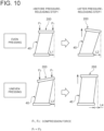
- FIG. 10 is a conceptual perspective view of the plate laminate 40 before and after the pressure-releasing step (S21) according to an embodiment of the present disclosure.
- the input point P of pressing force by the pressing tool 200 is conceptually illustrated by focusing on two points.
- the plate laminate 40 when the pressing force is released by the execution of the pressure-releasing step, the plate laminate 40 slightly returns to its original position in the laminating direction, although it is restrained by the pair of binding plates 120 and the connector 130.
- the amount of restoration in the laminating direction is 1% or less of the length of the plate laminate 40 in the laminating direction, more specifically 0.5 % or less.
- the plate laminate 40 may tilt with the execution of the pressure-releasing step.
- the reasons for the tilt are as follows.
- the strain generated inside the plate laminate 40 with the execution of the fastening step (S15) is unevenly distributed in the plate laminate 40. This may be due to the fact that the plurality of plates 44 of the plate laminate 40 are not strictly identical in shape, and that there are differences in the arrangement pattern (e.g., density) of the plurality of corrugated portions 43 in a single plate 44. In particular, if the density of the corrugated portions 43 is non-uniform in a single plate 44, the amount of strain in this plate 44 is non-uniform.
- dimension L2 is larger than dimension L1.
- the dimension L1 may be zero.
- the fastening step (S15) an adjustment is performed to vary the pressing force in at least two of the plurality of input points P, based on the fact that the amount of restoration in the laminating direction is not uniform (lower part of FIG. 10 ). Accordingly, the pressing force is greater on one side, where the amount of restoration tends to be greater, so that the amount of elastic deformation of the plate laminate 40 increases on one side.
- the connecting step (S19) is executed in the fastening state with the amount of elastic deformation adjusted in this manner, and the plate laminate 40 with variation in the amount of elastic deformation is held (restrained) by the connector 130.
- the pressure-releasing step (S21) when executed, the amount of restoration on one side of the plate laminate 40 is reduced by the adjusted amount of elastic deformation since it is restrained by the connector 130. Thus, the amount of restoration of the plate laminate 40 becomes uniform.
- dimension L4 is smaller than dimension L2, and the tilting of the plate laminate 40 is suppressed. Therefore, the plate laminate unit 100 with suppressed tilting can be produced.
- the amount of uniform restoration caused in the plate laminate 40 by varying the pressing force and the amount of non-uniform restoration caused in the plate laminate 40 by equalizing the pressing force are both 1% or less of the length of the plate laminate 40 in the laminating direction, more specifically 0.5 % or less.
- the gap between the inner wall surface of the vessel 35 of the heat exchanger 30 and the plate laminate 40 housed in the vessel 35 should be small.
- the tilting of the plate laminate 40 is suppressed, the variation in external dimension of the plate laminate 40 can be controlled, and the plate laminate 40 with the small gap can be produced.
- the plate laminate 40 housed in the vessel 35 having a specified dimension can be made larger, and thus the heat exchanger 30 that promotes heat exchange between the first heating medium T and the second heating medium R in the heat exchanger 30 can be achieved.
- At least two input points P with different pressing forces include a pair of input points Pc.
- the pair of input points Pc are located on both sides of the plate laminate 40 in the longitudinal direction of the plates 44, one on each side, in laminating direction view. According to the inventors' findings, the strain generated in the plate laminate 40 with the execution of the fastening step (S15) tends to be non-uniform in the longitudinal direction of the plates 44. With the above configuration, since the compression force applied to both longitudinal ends of each of the plurality of plates 44 is non-uniform, it is possible to effectively suppress the tilting of the plate laminate 40 after the pressure-releasing step (S21) is executed.
- the pressing force may also vary among two or more input points P other than the pair of input points Pc of the plurality of input points P. If uneven distribution of strain in the plate laminate 40 (uneven distribution of restoration in the plate laminate 40) when the pressing force is evenly applied to the plate laminate 40 is known in advance, it is also known how to vary the pressing force among the plurality of input points P. As a result, it is possible to more effectively suppress the tilting of the plate laminate 40 after the pressure-releasing step (S21) is executed.
- the edge portion (49) of the plate laminate (40) can be brought into close contact with the edge portions (119) of the pair of terminal plates (110) over the entire circumferential length. Since the welding step (S17) is executed with the edge portions (49, 119) in close contact, the edge portion (49) of the plate laminate (40) can be properly welded to the edge portions (119) of the pair of terminal plates (110) over the entire circumferential length. Additionally, since the edge portions (49, 119) are welded before the connecting step (S19), the connector (130) does not interfere with the welding step (S17).
- the connector (130) prevents the compressed plate laminate (40) from returning to the original position, and tensile stress at the weld portions (150) generated by the welding step (S17) is suppressed.
- the connector 130 receives this force, thereby suppressing tensile stress at the weld portions (150). Therefore, it is possible to achieve the method of producing the plate laminate unit (100) for a heat exchanger that can be applied to the use of the heat exchanger (30).
- the strain generated in the plate laminate (40) during the compressing step (S13, S15) tends to be non-uniform.
- the amount of restoration of the plate laminate (40) in the laminating direction with the execution of the pressure-releasing step (S21) is not uniform. Therefore, when the pressure-releasing step (S21) is executed, the laminating direction of the plate laminate (40) changes, and the plate laminate (40) tends to tilt.
- the pressing force in the compressing step (S13, S15) is varied in at least two of the plurality of input points (P) based on the fact that the amount of restoration in the laminating direction is not uniform, so that a relatively large compression force is applied to the area of the plate laminate (40) that is known to have a large restoration amount.
- the connecting step (S19) is executed in the fastening state with the amount of elastic deformation adjusted to increase in this area, and the plate laminate (40) with variation in the amount of elastic deformation is held.
- the plate laminate unit (100) with suppressed tilting can be produced. This allows the variation in external dimension of the plate laminate (40) to be controlled.
- the plate laminate (40) housed in the vessel (35) of the heat exchanger (30) having a specified dimension can be made larger, and the heat exchanger (30) that promotes heat exchange can be achieved.
- the plate laminate (40) in the method of producing the plate laminate unit (100) for a heat exchanger as defined in the above 2), includes a plurality of plates (44). Each of the plurality of plates (44) has a first edge portion (71) of arc shape and a second edge portion (72) with a smaller curvature than the first edge portion.
- the at least two input points (P) with different pressing forces are located on both sides of the plate laminate (40) in a longitudinal direction of the plates (44), at least one on each side, in laminating direction view.
- the strain generated in the plate laminate (40) with the execution of the compressing step (S13, S15) tends to be non-uniform in the longitudinal direction of the plates (44).
- the configuration 3 since the compression force applied to both longitudinal ends of each of the plurality of plates (44) is non-uniform, it is possible to effectively suppress the tilting of the plate laminate (40) after the pressure-releasing step (S21) is executed.
- the compressing step (S13, S15) includes: a placing step (S13) of placing a pair of pressing tables (210) included in the pressing tool (200) on both sides of the pair of binding plates (120) in the laminating direction; and a fastening step (S15) of tightening the pair of pressing tables (210), using a plurality of fastening shafts (220) included in the pressing tool (200) in a plurality of positions off the plate laminate (40), the pair of terminal plates (110), and the pair of binding plates (120) in laminating direction view.
- the pair of pressing tables (210) are tightened with the plurality of fastening shafts (220) separated from the plate laminate (40), the terminal plates (110), and the pair of binding plates (120). This ensures that the plurality of fastening shafts (220) do not interfere with the execution of the welding step (S17) after the fastening step (S15). Thus, the welding step (S17) can be simplified.
- the connecting step (S19) includes connecting edge portions (129) of the pair of binding plates (120) formed to surround the plate laminate (40) in laminating direction view by the connector (130).
- the connector (130) is separated from the plate laminate (40) and connected to the pair of binding plates (120). Therefore, the plate laminate (40) does not interfere with the execution of the connecting step (S19), and the connecting step (S19) can be simplified.
- the plate laminate (40) in the method of producing the plate laminate unit (100) for a heat exchanger as defined in any one of the above 1) to 5), includes a plurality of plates (44) each of which has a corrugated portion (43) to form a flow path (first flow path 31) for fluid (first heating medium).
- the compressing step (S13, S15) includes bringing the corrugated portions (43) of adjacent two of the plurality of plates (44) in the laminating direction into close contact with each other.
- the pair of binding plates (120) and the connector (130) prevent the plate laminate (40) from returning to the original position, so that the corrugated portions (43) of the two adjacent plates (44) can remain in contact with each other.
- This increases the flow path length of the flow path (first flow path 31) for fluid (first heating medium T), thus promoting heat exchange in the plate laminate (40).
Landscapes
- Engineering & Computer Science (AREA)
- Mechanical Engineering (AREA)
- Physics & Mathematics (AREA)
- Thermal Sciences (AREA)
- General Engineering & Computer Science (AREA)
- Optics & Photonics (AREA)
- Heat-Exchange Devices With Radiators And Conduit Assemblies (AREA)
Abstract
Description
- The present disclosure relates to a method of producing a plate laminate unit for a heat exchanger.
- The heat exchanger disclosed in Patent Document 1 contains a plate laminate configured to exchange heat between CO2 refrigerant and NH3 refrigerant. The plate laminate includes a plurality of plates welded together and a pair of terminal plates that sandwiches the plurality of plates from both sides in the laminating direction. One of the pairs of terminal plates illustrated in this document closes the flow path for the CO2 refrigerant. The other terminal plate has an inlet tube and an outlet tube. Both the inlet and outlet tubes communicate with the CO2 refrigerant path formed in the plate laminate.
- Patent Document 1:
JP5690532B - The edge portions of the pair of terminal plates must be properly welded to the edge portion of the plate laminate to prevent leakage of the CO2 refrigerant. In this regard, Patent Document 1 does not disclose any specific method for proper welding.
- An object of the present disclosure is to provide a method of producing a plate laminate unit for a heat exchanger whereby it is possible to properly weld a pair of terminal plates and a plate laminate.
- A method of producing a plate laminate unit for a heat exchanger according to at least one embodiment of the present disclosure includes: a compressing step of compressing a plate laminate, a pair of terminal plates disposed on both sides of the plate laminate in a laminating direction, and a pair of binding plates disposed on both sides of the pair of terminal plates in the laminating direction, using a pressing tool from both sides in the laminating direction; a welding step of welding an edge portion of the plate laminate to edge portions of the pair of terminal plates during the compressing step; a connecting step of connecting the pair of binding plates to each other by a connector after the welding step; and a pressure-releasing step of detaching the pressing tool after the connecting step.
- The present disclosure provides a method of producing a plate laminate unit for a heat exchanger whereby it is possible to properly weld a pair of terminal plates and a plate laminate.
-
-
FIG. 1 is a conceptual cross-sectional view of a heat exchanger according to an embodiment. -
FIG. 2 is a conceptual exploded perspective view of a plate laminate unit according to an embodiment. -
FIG. 3 is a conceptual perspective view of a plate laminate according to an embodiment. -
FIG. 4 is a conceptual explanatory view of a plate laminate unit according to an embodiment in laminating direction view. -
FIG. 5 is a flowchart of the method of producing a plate laminate unit according to an embodiment. -
FIG. 6 is a conceptual explanatory view of the method of assembling a paired plate according to an embodiment. -
FIG. 7 is a conceptual explanatory view of the placing step according to an embodiment. -
FIG. 8 is a conceptual explanatory view of the fastening step according to an embodiment. -
FIG. 9 is a conceptual explanatory view of the connecting step according to an embodiment. -
FIG. 10 is a conceptual perspective view of a plate laminate before and after the pressure-releasing step according to an embodiment. - Embodiments of the present disclosure will be described below with reference to the accompanying drawings. It is intended, however, that unless particularly identified, dimensions, materials, shapes, relative positions, and the like of components described in the embodiments shall be interpreted as illustrative only and not intended to limit the scope of the present disclosure.
- For instance, an expression of relative or absolute arrangement such as "in a direction", "along a direction", "parallel", "orthogonal", "centered", "concentric" and "coaxial" shall not be construed as indicating only the arrangement in a strict literal sense, but also includes a state where the arrangement is relatively displaced by a tolerance, or by an angle or a distance whereby it is possible to achieve the same function.
- For instance, an expression of an equal state such as "same" "equal" and "uniform" shall not be construed as indicating only the state in which the feature is strictly equal, but also includes a state in which there is a tolerance or a difference that can still achieve the same function.
- Further, for instance, an expression of a shape such as a rectangular shape or a cylindrical shape shall not be construed as only the geometrically strict shape, but also includes a shape with unevenness or chamfered corners within the range in which the same effect can be achieved.
- On the other hand, an expression such as "comprise", "include", "have", "contain" and "constitute" are not intended to be exclusive of other components.
- The same features can be indicated by the same reference numerals and not described in detail.
-
FIG. 1 is a conceptual cross-sectional view of aheat exchanger 30 according to an embodiment of the present disclosure. Theheat exchanger 30 is configured so that a first heating medium T to circulate through aprimary refrigerant circuit 10 and a second heating medium R to circulate through asecondary refrigerant circuit 20 exchange heat with each other. The first heating medium T is NH3 in the gas or liquid phase as an example, and the second heating medium R is CO2 in the liquid phase as an example. The first heating medium T and the second heating medium R may be other fluids than those mentioned above. - The first heating medium liquid Te, which is the first heating medium T in the liquid phase flowing into the
heat exchanger 30, is transformed into the first heating medium gas Tv by the heat obtained from the second heating medium R. In other words, in theprimary refrigerant circuit 10, theheat exchanger 30 functions as an evaporator for the first heating medium T. The flow phase of the first heating medium T flowing into theheat exchanger 30 may be gas-liquid two-phase. The first heating medium gas Tv flowing out of theheat exchanger 30 transforms to the first heating medium liquid Te in the process of circulating in theprimary refrigerant circuit 10 and returns to theheat exchanger 30. Theprimary refrigerant circuit 10 includes a compressor, a condenser, and an expansion valve. On the other hand, the cold energy of the second heating medium R cooled by heat exchange with the first heating medium T is extracted in the process of circulating in thesecondary refrigerant circuit 20. The second heating medium R is heated up and returns to theheat exchanger 30. Thesecondary refrigerant circuit 20 includes a liquid receiver (receiver), a pump, and a cooler. The cooler is configured to extract cold energy from the second heating medium R. For example, the cooler may be configured to exchange heat between the second heating medium R circulating in thesecondary refrigerant circuit 20 and a heating medium such as air circulating in a freezer. - The
heat exchanger 30 in this example is a plate heat exchanger, more specifically a shell-and-plate heat exchanger. Theheat exchanger 30 includes, for example, avessel 35 in which a liquid pool of the first heating medium liquid Te is formed, and aplate laminate unit 100 which is immersed in the liquid pool of the first heating medium liquid Te. Thevessel 35 in this example is formed in a cylindrical shape extending in the laminating direction of theplate laminate 40 included in theplate laminate unit 100. Thevessel 35 is provided with adelivery tube 50 for delivering the first heating medium liquid Te to theplate laminate 40 and adischarge duct 60 for discharging the first heating medium gas Tv produced inside thevessel 35. Thedischarge duct 60 has a plurality ofcommunication openings 63 through which the first heating medium gas Tv can flow into the duct. In this example, the second heating medium R flows inside theplate laminate 40 immersed in the pool of the first heating medium liquid Te, where the first heating medium liquid Te and the second heating medium R exchange heat. The first heating medium gas Tv produced by the heat exchange is discharged from theheat exchanger 30 through thedischarge duct 60. -
FIG. 2 is a conceptual exploded perspective view of theplate laminate unit 100 according to an embodiment of the present disclosure.FIG. 3 is a conceptual perspective view of theplate laminate 40 according to an embodiment of the present disclosure.FIG. 4 is a conceptual explanatory view of theplate laminate unit 100 according to an embodiment of the present disclosure in laminating direction view. - As shown in
FIG. 2 , theplate laminate unit 100 includes aplate laminate 40 comprising a plurality oflaminated plates 44. The laminating direction of theplate laminate 40 coincides with the thickness direction of eachplate 44. Theplate laminate unit 100 further includes a pair ofterminal plates 110 disposed on both sides of theplate laminate 40 in the laminating direction, a pair of bindingplates 120 disposed on both sides of the pair ofterminal plates 110 in the laminating direction, and aconnector 130 connecting the pair of bindingplates 120 to each other. - As shown in
FIGs. 2 and3 , each of the plurality ofplates 44 of theplate laminate 40 has afirst communication opening 41 and asecond communication opening 42. Both thefirst communication opening 41 and the second communication opening 42 form parts of asecond flow path 32, which is the flow path for the second heating medium R. The wall surface of eachplate 44 has a plurality of linearly-extendingcorrugated portions 43. Thecorrugated portions 43 are formed by press working as an example; acorrugated portion 43 on one side is protruded, and thecorrugated portion 43 on the other side is recessed. It is understood that the space between protruded portions, which correspond to the plurality ofcorrugated portions 43 on one side, are recessed portions. In accordance with the same concept, it is understood that the space between recessed portions, which correspond to the plurality ofcorrugated portions 43 on the other side, are protruded portions. - As shown in
FIG. 3 , theplate laminate 40 has multiple sets of pairedplates 47 each of which is composed of a pair ofplates 44. In the pair ofplates 44, the edge portions of the twofirst communication openings 41 are welded together, and the edge portions of the twosecond communication openings 42 are welded together. Theouter edge portions 49 of the pair ofplates 44 are not welded, so afirst flow path 31, which is the flow path for the first heating medium T, is formed between the pair ofplates 44. The respective inner spaces of thefirst communication openings 41 and thesecond communication openings 42 are separated from thefirst flow path 31 by welds formed at the edge portions of thefirst communication openings 41 and thesecond communication openings 42. The pair ofplates 44 constituting each pairedplate 47 are arranged so that the protruded portions of thecorrugated portions 43 face each other. The pair ofplates 44 are pressed against each other (compressed) so that thesecorrugated portions 43 are in close contact with each other, which increases the flow path length of thefirst flow path 31 and promotes heat exchange between the first heating medium T and the second heating medium R. - Two sets of paired
plates 47 adjacent to each other in the laminating direction are welded together at theirouter edge portions 49. This creates thesecond flow path 32 for the second heating medium R between the two pairedplates 47, which is separated from the interior space of thevessel 35. - The
first communication opening 41 on one side in the laminating direction of theplate laminate 40 having the above configuration communicates with aninlet tube 7, and the second communication opening 42 communicates with anoutlet tube 6. Theedge portion 49 of eachplate 44 in this embodiment has afirst edge portion 71 of arc shape and asecond edge portion 72 with a smaller curvature than thefirst edge portion 71. Accordingly, eachplate 44 has a longitudinal direction and a transverse direction in laminating direction view. Thesecond edge portion 72 is longer in the longitudinal direction than thefirst edge portion 71 and is located above thefirst edge portion 71. Therefore, the first heating medium liquid Te delivered from thedelivery tube 50 easily hits eachplate 44, promoting heat exchange between the first heating medium T and the second heating medium R. Thesecond edge portion 72 may be curved or flattened. On the other hand, thefirst edge portion 71, which is located on the lower side, does not necessarily have to present a shape that is easily hit by the delivered first heating medium liquid Te. The smaller the gap between thefirst edge portion 71 and the inner wall surface of thevessel 35, the larger theplate 44 can be, and the more heat exchange between the first heating medium T and the second heating medium R can be promoted. Therefore, thefirst edge portion 71 is preferably arc-shaped in accordance with thecylindrical vessel 35. In other embodiments, eachplate 44 may be circular or oval. - Returning to
FIG. 2 , each of the pair ofterminal plates 110 has substantially the same external shape as the plurality ofplates 44. The pair ofterminal plates 110 are welded to the outermost pair ofplates 44 in the laminating direction of the plurality ofplates 44, respectively. As a more specific example, theedge portion 49 of eachplate 44 and theedge portion 119 of eachterminal plate 110 are welded together along their entire circumferential length. Theinlet tube 7 and theoutlet tube 6 are welded to theterminal plate 110 on one side in the laminating direction. As described above, theinlet tube 7 and theoutlet tube 6 respectively communicate with thefirst communication opening 41 and the second communication opening 42 of theplate 44 located on one side. - The
binding plate 120 shown inFIGs. 2 and4 has afirst opening 121 and asecond opening 122 through which theinlet tube 7 and theoutlet tube 6 are placed inside, respectively (theterminal plate 110 is not shown inFIG. 4 ). Theedge portion 129 of thebinding plate 120 is formed to surround theedge portion 49 of theplate laminate 40 in laminating direction view. In other words, in laminating direction view, theedge portion 129 is located outward of theedge portion 49 over the entire circumferential length of theedge portion 129. Theconnector 130 is a bar extending in the laminating direction. In this example, the ends of each of a plurality ofconnectors 130 are welded to therespective edge portions 129 of the pair of bindingplates 120. Since theedge portion 129 is located outward of theedge portion 49 in laminating direction view, the plurality ofconnectors 130 are all separated from theplate laminate 40 and the pair ofterminal plates 110. - As described above, the
plate laminate 40 is placed in a compressed state, and at least a portion of theplate laminate 40 is elastically deformed in the laminating direction. The pair of bindingplates 120 and theconnector 130 prevent thecompressed plate laminate 40 from returning to the original position. In other words, tensile stress due to the restoring force of theplate laminate 40 acts on the plurality ofconnectors 130. A portion of thecompressed plate laminate 40 may be plastically deformed. -
FIG. 5 is a flowchart of the method of producing theplate laminate unit 100 for a heat exchanger according to an embodiment of the present disclosure (in the following description, "step" may be abbreviated as "S").FIG. 6 is a conceptual explanatory view of the method of assembling the pairedplate 47 according to an embodiment of the present disclosure.FIG. 7 is a conceptual explanatory view of the placing step according to an embodiment of the present disclosure.FIG. 8 is a conceptual explanatory view of the fastening step according to an embodiment of the present disclosure.FIG. 9 is a conceptual explanatory view of the connecting step according to an embodiment of the present disclosure. - As shown in
FIG. 5 , first, the step of assembling theplate laminate 40 is performed (S11). For example, as shown inFIG. 6 , the edge portions of respectivefirst communication openings 41 of a pair ofplates 44 are welded together, and the edge portions of respectivesecond communication openings 42 are welded together. Thus, the pairedplate 47 is completed. At this time, respectivecorrugated portions 43 of the pair ofplates 44 do not have to be adhered to each other. The process of producing the pairedplate 47 is repeated, and multiple sets of pairedplates 47 are prepared. Then, the process of welding theedge portions 49 of one set of paredplates 47 is repeated, as shown inFIG. 3 . Thus, the assembly of theplate laminate 40 is completed. - Returning to
FIG. 5 , various components necessary to produce theplate laminate unit 100 are placed (S13). For example, apressing tool 200 for compressing theplate laminate unit 100 is prepared, as shown inFIG. 7 . Thepressing tool 200 includes a pair of pressing tables 210, a plurality of fastening shafts 220 (seeFIG. 8 ), and a plurality of nuts (not shown). On one of the pressing tables located at the bottom, thebinding plate 120, theterminal plate 110, theplate laminate 40, theterminal plate 110, and thebinding plate 120 are placed in order from the bottom. The other pressing table 210 is then placed on the top of thebinding plate 120. Thus, theplate laminate 40, the pair ofterminal plates 110, the pair of bindingplates 120, and the pair of pressing tables 210 are placed in order from the inside in the laminating direction (from the center side in the laminating direction of the plate laminate 40). - The edge portions of the pressing tables 210 surround the pair of binding
plates 120 in laminating direction view. In other words, in laminating direction view, the edge portions of the pressing tables 210 are located outward of theedge portions 129 of thebinding plates 120 over the entire circumferential length. Further, each pressing table 210 has a plurality of insertion holes 212. The plurality ofinsertion holes 212 are all located outward of theedge portions 129 of the pair of bindingplates 120 in laminating direction view. In other words, eachinsertion hole 212 is in a position off theplate laminate 40, the pair ofterminal plates 110, and the pair of bindingplates 120 in the laminating direction. The plurality ofinsertion holes 212 are open in the laminating direction and also open along the horizontal direction perpendicular to the laminating direction. Further, twoinsertion holes 212A of the plurality ofinsertion holes 212 are located such that both longitudinal ends of eachplate 44 are interposed between the two holes in laminating direction view. - Returning to
FIG. 5 , the fastening step is executed to tighten the pair of pressing tables 210 of the pressing tool 200 (S15). For example, as shown inFIG. 8 , the plurality offastening shafts 220 are inserted into the plurality ofinsertion holes 212, respectively. The outer peripheral surface of eachfastening shaft 220 is threaded, and a plurality of nuts (not shown) are attached to the upper end portions of the plurality of insertedfastening shafts 220, respectively. Each nut is tightened so that it is pressed against the pressing table 210 from above. This applies a pressing force to the upper pressing table 210 to tighten the pair of pressing tables 210. In other words, the pair of pressing tables 210 applies a compression force to theplate laminate 40 via the pair of bindingplates 120 and the pair ofterminal plates 110. As a result, theplate laminate 40 is compressed, and thecorrugated portions 43 of the twoplates 44 constituting the pairedplate 47 come into close contact with each other. Further, the pair of bindingplates 120 come closer to each other as theplate laminate 40 is compressed. - The contact positions between the edges of the plurality of
insertion holes 212 and the plurality of nuts are input points P where the pressing force is applied. The number of input points P in this example is six. The plurality of input points P are located so as to surround theplate laminate 40 in laminating direction view. Different pressing forces act in at least two of the plurality of input points P on the upper pressing table 210. In other words, the amount of nut tightening varies among at least two of the plurality of input points P. The advantages of different pressing forces are discussed below. - To add, when the
fastening shaft 220 is inserted into theinsertion hole 212 along the vertical direction, the more the length of theplate laminate 40 in the laminating direction increases, the more the workability of insertion may decrease. In this regard, in this embodiment, since eachinsertion hole 212 is open in the horizontal direction, thefastening shaft 220 can be inserted into theinsertion hole 212 along the horizontal direction. Therefore, even if theplate laminate 40 is long in the laminating direction, the workability of insertion is not impaired. - Returning to
FIGs. 5 and8 , the welding step is executed to weld theedge portion 49 of theplate laminate 40 to theedge portions 119 of the pair of terminal plates 110 (S17). At this time, with pressure applied by thepressing tool 200, theedge portions edge portions weld portions 150 are properly formed along their entire circumferential length. - As shown in
FIGs. 5 and9 , the connecting step is then executed to connect the pair of bindingplates 120 to each other by the connector 130 (S19). In the example ofFIG. 9 , the ends of each of the plurality ofconnectors 130 extending in the laminating direction are connected to therespective edge portions 129 of the pair of bindingplates 120 by welding. Thus, theplate laminate unit 100 is assembled while being pressed by thepressing tool 200. - Returning to
FIG. 5 , the pressure-releasing step is executed to detach the pressing tool 200 (S21). More specifically, the plurality of nuts are removed from the plurality offastening shafts 220, respectively. This ends the compression using thepressing tool 200, but theplate laminate 40 is still restrained in a compressed state by the pair of bindingplates 120 and theconnector 130. Therefore, even after the compression by thepressing tool 200 is completed, theplate laminate 40 remains compressed with almost no restoration. The plurality offastening shafts 220 and the upper pressing table 210 are then removed, and theplate laminate unit 100 is taken out. The production of theplate laminate unit 100 is thus completed. The portableplate laminate unit 100 is then housed in thevessel 35 of theheat exchanger 30. - With the above configuration, through the execution of S13 and S15, the compressing step of compressing the
plate laminate 40, the pair ofterminal plates 110, and the pair of bindingplates 120 using thepressing tool 200 from both sides in the laminating direction, theedge portion 49 of theplate laminate 40 can be brought into close contact with theedge portions 119 of the pair ofterminal plates 110 over the entire circumferential length. Since the welding step (S17) is executed with theedge portions edge portions edge portions connector 130 does not interfere with the welding step (S17). From the above, it is possible to achieve the method of producing theplate laminate unit 100 for a heat exchanger by which theplate laminate 40 and the pair ofterminal plates 110 can be welded easily and properly. Further, even after the pressure-releasing process (S21) is executed, theconnector 130 prevents thecompressed plate laminate 40 from returning to the original position, and tensile stress at theweld portions 150 is suppressed. More specifically, even if a large force is generated to separate theplate laminate 40 from theterminal plates 110 due to the second heating medium R as a high-pressure fluid flowing through thesecond flow path 32 of theplate laminate 40, theconnector 130 receives this force, thereby suppressing tensile stress at theweld portions 150. Therefore, it is possible to achieve the method of producing theplate laminate unit 100 for a heat exchanger that can be applied to the use of theheat exchanger 30. - In the fastening step (S15), in each of a plurality of positions (in this embodiment, a plurality of input points P) off the
plate laminate 40, the pair ofterminal plates 110, and the pair of bindingplates 120 in laminating direction view, the pair of pressing tables 210 are tightened using the plurality offastening shafts 220 included in thepressing tool 200. With the above configuration, the pair of pressing tables 210 are tightened with the plurality offastening shafts 220 separated from theplate laminate 40, theterminal plates 110, and the pair of bindingplates 120. This ensures that the plurality offastening shafts 220 do not interfere with the execution of the welding step (S17) after the fastening step. Thus, the welding step can be simplified. - Further, in the connecting step (S19), the
edge portions 129 of the pair of bindingplates 120, which are formed to surround theplate laminate 40 in laminating direction view, are connected by theconnector 130. With the above configuration, since theedge portions 129 of thebinding plates 120 are formed to surround theplate laminate 40 in laminating direction view, theconnector 130 is separated from theplate laminate 40 and connected to the pair of bindingplates 120. Therefore, theplate laminate 40 does not interfere with the execution of the connecting step (S19), and the connecting step (S19) can be simplified. - The
plate laminate 40 includes a plurality ofplates 44 withcorrugated portions 43 forming thefirst flow path 31 and thesecond flow path 32. In S13 and S15, which correspond to the compressing step described above, the respectivecorrugated portions 43 of twoplates 44 adjacent to each other in the laminating direction of the plurality ofplates 44 are brought into close contact with each other. With the above configuration, even after the pressure-releasing step (S21) is executed, the pair ofplates 44 and theconnector 130 prevent theplate laminate 40 from returning to the original position, so that thecorrugated portions 43 of the twoadjacent plates 44 can remain in contact with each other. This increases the flow path length of thefirst flow path 31, thus promoting heat exchange in theplate laminate 40. - Referring to
FIGs. 9 and10 , the advantages of different pressing forces depending on the input point P in the fastening step (S15) will be described.FIG. 10 is a conceptual perspective view of theplate laminate 40 before and after the pressure-releasing step (S21) according to an embodiment of the present disclosure. InFIG. 10 , for ease of explanation, the input point P of pressing force by thepressing tool 200 is conceptually illustrated by focusing on two points. - As shown in
FIG. 10 , when the pressing force is released by the execution of the pressure-releasing step, theplate laminate 40 slightly returns to its original position in the laminating direction, although it is restrained by the pair of bindingplates 120 and theconnector 130. The amount of restoration in the laminating direction is 1% or less of the length of theplate laminate 40 in the laminating direction, more specifically 0.5 % or less. - However, even if the amount of restoration is small, the
plate laminate 40 may tilt with the execution of the pressure-releasing step. The reasons for the tilt are as follows. - The strain generated inside the
plate laminate 40 with the execution of the fastening step (S15) is unevenly distributed in theplate laminate 40. This may be due to the fact that the plurality ofplates 44 of theplate laminate 40 are not strictly identical in shape, and that there are differences in the arrangement pattern (e.g., density) of the plurality ofcorrugated portions 43 in asingle plate 44. In particular, if the density of thecorrugated portions 43 is non-uniform in asingle plate 44, the amount of strain in thisplate 44 is non-uniform. As a result, when pressing force is evenly applied to theplate laminate 40, the amount of restoration of theplate laminate 40 observed as a result of the execution of the pressure-releasing step (S21) becomes non-uniform, the laminating direction of theplate laminate 40 changes, and theplate laminate 40 tilts. According to the inventors' knowledge, which way it tilts depends on the positions of the plurality of input points P, the shape of theplate laminate 40, the arrangement pattern of thecorrugated portions 43, the shape of eachcorrugated portion 43, etc. In the upper example inFIG. 10 , a relatively large strain (relatively large compression) appears on one side (left side in the example ofFIG. 10 ) in theplate laminate 40, even though pressing force is evenly applied in the fastening step. As a result, the amount of restoration in theplate laminate 40 due to the execution of the pressure-releasing step is greater on one side of theplate laminate 40, and the tilt of theplate laminate 40 increases with the execution of the pressure-releasing step. In the example ofFIG. 10 , dimension L2 is larger than dimension L1. The dimension L1 may be zero. - In this regard, in the present embodiment, in the fastening step (S15), an adjustment is performed to vary the pressing force in at least two of the plurality of input points P, based on the fact that the amount of restoration in the laminating direction is not uniform (lower part of
FIG. 10 ). Accordingly, the pressing force is greater on one side, where the amount of restoration tends to be greater, so that the amount of elastic deformation of theplate laminate 40 increases on one side. The connecting step (S19) is executed in the fastening state with the amount of elastic deformation adjusted in this manner, and theplate laminate 40 with variation in the amount of elastic deformation is held (restrained) by theconnector 130. Therefore, when the pressure-releasing step (S21) is executed, the amount of restoration on one side of theplate laminate 40 is reduced by the adjusted amount of elastic deformation since it is restrained by theconnector 130. Thus, the amount of restoration of theplate laminate 40 becomes uniform. In the example ofFIG. 10 , dimension L4 is smaller than dimension L2, and the tilting of theplate laminate 40 is suppressed. Therefore, theplate laminate unit 100 with suppressed tilting can be produced. The amount of uniform restoration caused in theplate laminate 40 by varying the pressing force and the amount of non-uniform restoration caused in theplate laminate 40 by equalizing the pressing force are both 1% or less of the length of theplate laminate 40 in the laminating direction, more specifically 0.5 % or less. - As described above, the gap between the inner wall surface of the
vessel 35 of theheat exchanger 30 and theplate laminate 40 housed in thevessel 35 should be small. In this regard, since the tilting of theplate laminate 40 is suppressed, the variation in external dimension of theplate laminate 40 can be controlled, and theplate laminate 40 with the small gap can be produced. In other words, theplate laminate 40 housed in thevessel 35 having a specified dimension can be made larger, and thus theheat exchanger 30 that promotes heat exchange between the first heating medium T and the second heating medium R in theheat exchanger 30 can be achieved. - Returning to
FIG. 8 , at least two input points P with different pressing forces include a pair of input points Pc. The pair of input points Pc are located on both sides of theplate laminate 40 in the longitudinal direction of theplates 44, one on each side, in laminating direction view. According to the inventors' findings, the strain generated in theplate laminate 40 with the execution of the fastening step (S15) tends to be non-uniform in the longitudinal direction of theplates 44. With the above configuration, since the compression force applied to both longitudinal ends of each of the plurality ofplates 44 is non-uniform, it is possible to effectively suppress the tilting of theplate laminate 40 after the pressure-releasing step (S21) is executed. - In other embodiments, the pressing force may also vary among two or more input points P other than the pair of input points Pc of the plurality of input points P. If uneven distribution of strain in the plate laminate 40 (uneven distribution of restoration in the plate laminate 40) when the pressing force is evenly applied to the
plate laminate 40 is known in advance, it is also known how to vary the pressing force among the plurality of input points P. As a result, it is possible to more effectively suppress the tilting of theplate laminate 40 after the pressure-releasing step (S21) is executed. - The contents described in the above embodiments would be understood as follows, for instance.
- 1) A method of producing a plate laminate unit (100) for a heat exchanger according to at least one embodiment of the present disclosure includes: a compressing step (S13, S15) of compressing a plate laminate (40), a pair of terminal plates (110) disposed on both sides of the plate laminate (40) in a laminating direction, and a pair of binding plates (120) disposed on both sides of the pair of terminal plates (110) in the laminating direction, using a pressing tool (200) from both sides in the laminating direction; a welding step (S17) of welding an edge portion (49) of the plate laminate (40) to edge portions (119) of the pair of terminal plates (110) during the compressing step (S13, S15); a connecting step (S19) of connecting the pair of binding plates (120) to each other by a connector (130) after the welding step (S17); and a pressure-releasing step (S21) of detaching the pressing tool (200) after the connecting step.
- With the configuration 1), through the execution of the compressing step (S13, S15), the edge portion (49) of the plate laminate (40) can be brought into close contact with the edge portions (119) of the pair of terminal plates (110) over the entire circumferential length. Since the welding step (S17) is executed with the edge portions (49, 119) in close contact, the edge portion (49) of the plate laminate (40) can be properly welded to the edge portions (119) of the pair of terminal plates (110) over the entire circumferential length. Additionally, since the edge portions (49, 119) are welded before the connecting step (S19), the connector (130) does not interfere with the welding step (S17). From the above, it is possible to achieve the method of producing the plate laminate unit (100) for a heat exchanger by which the plate laminate (40) and the pair of terminal plates (110) can be welded easily and properly. Further, even after the pressure-releasing step (S21) is executed, the connector (130) prevents the compressed plate laminate (40) from returning to the original position, and tensile stress at the weld portions (150) generated by the welding step (S17) is suppressed. For example, even if a large force is generated to separate the plate laminate (40) from the terminal plates (110) due to a high-pressure fluid (second heating medium R) flowing through the flow path (second flow path 32) of the plate laminate (40), the
connector 130 receives this force, thereby suppressing tensile stress at the weld portions (150). Therefore, it is possible to achieve the method of producing the plate laminate unit (100) for a heat exchanger that can be applied to the use of the heat exchanger (30). - 2) In some embodiments, in the method of producing the plate laminate unit (100) for a heat exchanger as defined in the above 1), in the compressing step (S13, S15), different pressing forces act in at least two of a plurality of input points (P) of pressing force of the pressing tool (200) located to surround the plate laminate (40) in laminating direction view.
- The strain generated in the plate laminate (40) during the compressing step (S13, S15) tends to be non-uniform. In this case, the amount of restoration of the plate laminate (40) in the laminating direction with the execution of the pressure-releasing step (S21) is not uniform. Therefore, when the pressure-releasing step (S21) is executed, the laminating direction of the plate laminate (40) changes, and the plate laminate (40) tends to tilt. In this regard, with the configuration 2), the pressing force in the compressing step (S13, S15) is varied in at least two of the plurality of input points (P) based on the fact that the amount of restoration in the laminating direction is not uniform, so that a relatively large compression force is applied to the area of the plate laminate (40) that is known to have a large restoration amount. Then, the connecting step (S19) is executed in the fastening state with the amount of elastic deformation adjusted to increase in this area, and the plate laminate (40) with variation in the amount of elastic deformation is held. As a result, the amount of restoration in the area where the amount of elastic deformation tends to increase is reduced when the pressure-releasing step (S21) is executed, and the amount of restoration of the plate laminate (40) becomes uniform. Therefore, the plate laminate unit (100) with suppressed tilting can be produced. This allows the variation in external dimension of the plate laminate (40) to be controlled. Thus, the plate laminate (40) housed in the vessel (35) of the heat exchanger (30) having a specified dimension can be made larger, and the heat exchanger (30) that promotes heat exchange can be achieved.
- 3) In some embodiments, in the method of producing the plate laminate unit (100) for a heat exchanger as defined in the above 2), the plate laminate (40) includes a plurality of plates (44). Each of the plurality of plates (44) has a first edge portion (71) of arc shape and a second edge portion (72) with a smaller curvature than the first edge portion. The at least two input points (P) with different pressing forces are located on both sides of the plate laminate (40) in a longitudinal direction of the plates (44), at least one on each side, in laminating direction view.
- According to the inventors' findings, the strain generated in the plate laminate (40) with the execution of the compressing step (S13, S15) tends to be non-uniform in the longitudinal direction of the plates (44). With the configuration 3), since the compression force applied to both longitudinal ends of each of the plurality of plates (44) is non-uniform, it is possible to effectively suppress the tilting of the plate laminate (40) after the pressure-releasing step (S21) is executed.
- 4) In some embodiments, in the method of producing the plate laminate unit (100) for a heat exchanger as defined in any one of the above 1) to 3), the compressing step (S13, S15) includes: a placing step (S13) of placing a pair of pressing tables (210) included in the pressing tool (200) on both sides of the pair of binding plates (120) in the laminating direction; and a fastening step (S15) of tightening the pair of pressing tables (210), using a plurality of fastening shafts (220) included in the pressing tool (200) in a plurality of positions off the plate laminate (40), the pair of terminal plates (110), and the pair of binding plates (120) in laminating direction view.
- With the configuration 4), the pair of pressing tables (210) are tightened with the plurality of fastening shafts (220) separated from the plate laminate (40), the terminal plates (110), and the pair of binding plates (120). This ensures that the plurality of fastening shafts (220) do not interfere with the execution of the welding step (S17) after the fastening step (S15). Thus, the welding step (S17) can be simplified.
- 5) In some embodiments, in the method of producing the plate laminate unit (100) for a heat exchanger as defined in any one of the above 1) to 4), the connecting step (S19) includes connecting edge portions (129) of the pair of binding plates (120) formed to surround the plate laminate (40) in laminating direction view by the connector (130).
- With the configuration 5), since the edge portions (129) of the binding plates (120) are formed to surround the plate laminate (40) in laminating direction view, the connector (130) is separated from the plate laminate (40) and connected to the pair of binding plates (120). Therefore, the plate laminate (40) does not interfere with the execution of the connecting step (S19), and the connecting step (S19) can be simplified.
- 6) In some embodiments, in the method of producing the plate laminate unit (100) for a heat exchanger as defined in any one of the above 1) to 5), the plate laminate (40) includes a plurality of plates (44) each of which has a corrugated portion (43) to form a flow path (first flow path 31) for fluid (first heating medium). The compressing step (S13, S15) includes bringing the corrugated portions (43) of adjacent two of the plurality of plates (44) in the laminating direction into close contact with each other.
- With the configuration 6), even after the pressure-releasing step (S21) is executed, the pair of binding plates (120) and the connector (130) prevent the plate laminate (40) from returning to the original position, so that the corrugated portions (43) of the two adjacent plates (44) can remain in contact with each other. This increases the flow path length of the flow path (first flow path 31) for fluid (first heating medium T), thus promoting heat exchange in the plate laminate (40).
-
- 30
- Heat exchanger
- 40
- Plate laminate
- 43
- Corrugated portion
- 44
- Plate
- 49, 119
- Edge portion
- 71
- First edge portion
- 72
- Second edge portion
- 100
- Plate laminate unit
- 110
- Terminal plate
- 120
- Binding plate
- 129
- Edge portion
- 130
- Connector
- 200
- Pressing tool
- 210
- Pressing table
- 220
- Fastening shaft
- P, Pc
- Input point
Claims (6)
- A method of producing a plate laminate unit for a heat exchanger, comprising:a compressing step of compressing a plate laminate, a pair of terminal plates disposed on both sides of the plate laminate in a laminating direction, and a pair of binding plates disposed on both sides of the pair of terminal plates in the laminating direction, using a pressing tool from both sides in the laminating direction;a welding step of welding an edge portion of the plate laminate to edge portions of the pair of terminal plates during the compressing step;a connecting step of connecting the pair of binding plates to each other by a connector after the welding step; anda pressure-releasing step of detaching the pressing tool after the connecting step.
- The method of producing the plate laminate unit for the heat exchanger according to claim 1,
wherein, in the compressing step, different pressing forces act in at least two of a plurality of input points of pressing force of the pressing tool located to surround the plate laminate in laminating direction view. - The method of producing the plate laminate unit for the heat exchanger according to claim 2,wherein the plate laminate includes a plurality of plates,wherein each of the plurality of plates has a first edge portion of arc shape and a second edge portion with a smaller curvature than the first edge portion, andwherein the at least two input points with different pressing forces are located on both sides of the plate laminate in a longitudinal direction of the plates, at least one on each side, in laminating direction view.
- The method of producing the plate laminate unit for the heat exchanger according to any one of claims 1 to 3,
wherein the compressing step includes:a placing step of placing a pair of pressing tables included in the pressing tool on both sides of the pair of binding plates in the laminating direction; anda fastening step of tightening the pair of pressing tables, using a plurality of fastening shafts included in the pressing tool in a plurality of positions off the plate laminate, the pair of terminal plates, and the pair of binding plates in laminating direction view. - The method of producing the plate laminate unit for the heat exchanger according to any one of claims 1 to 4,
wherein the connecting step includes connecting edge portions of the pair of binding plates formed to surround the plate laminate in laminating direction view by the connector. - The method of producing the plate laminate unit for the heat exchanger according to any one of claims 1 to 5,wherein the plate laminate includes a plurality of plates each of which has a corrugated portion to form a flow path for fluid, andwherein the compressing step includes bringing the corrugated portions of adjacent two of the plurality of plates in the laminating direction into close contact with each other.
Applications Claiming Priority (2)
| Application Number | Priority Date | Filing Date | Title |
|---|---|---|---|
| JP2021195869A JP7721417B2 (en) | 2021-12-02 | 2021-12-02 | Method for manufacturing plate stack unit for heat exchanger |
| PCT/JP2022/043654 WO2023100779A1 (en) | 2021-12-02 | 2022-11-28 | Manufacturing method for a plate laminate unit for a heat exchanger |
Publications (3)
| Publication Number | Publication Date |
|---|---|
| EP4414098A1 true EP4414098A1 (en) | 2024-08-14 |
| EP4414098A4 EP4414098A4 (en) | 2025-04-16 |
| EP4414098B1 EP4414098B1 (en) | 2026-01-14 |
Family
ID=86612171
Family Applications (1)
| Application Number | Title | Priority Date | Filing Date |
|---|---|---|---|
| EP22901212.5A Active EP4414098B1 (en) | 2021-12-02 | 2022-11-28 | Manufacturing method for a plate laminate unit for a heat exchanger |
Country Status (7)
| Country | Link |
|---|---|
| US (1) | US12305935B2 (en) |
| EP (1) | EP4414098B1 (en) |
| JP (1) | JP7721417B2 (en) |
| KR (1) | KR20240093904A (en) |
| CN (1) | CN118176070A (en) |
| FI (1) | FI4414098T3 (en) |
| WO (1) | WO2023100779A1 (en) |
Family Cites Families (7)
| Publication number | Priority date | Publication date | Assignee | Title |
|---|---|---|---|---|
| JPS5690532U (en) | 1979-12-15 | 1981-07-20 | ||
| JP5690532B2 (en) * | 2010-09-10 | 2015-03-25 | 株式会社前川製作所 | Shell and plate heat exchanger |
| EP2802835B1 (en) | 2012-01-12 | 2018-09-05 | Westinghouse Electric Company LLC | Modular plate and shell heat exchanger |
| JP2013196849A (en) * | 2012-03-16 | 2013-09-30 | Honda Motor Co Ltd | Fuel cell stack assembling method |
| JP6798762B2 (en) * | 2017-06-06 | 2020-12-09 | 株式会社前川製作所 | Refrigerant heat exchanger |
| KR102631208B1 (en) * | 2019-06-11 | 2024-01-31 | 가부시끼가이샤 마에가와 세이사꾸쇼 | Welding device for plate laminates and method for manufacturing plate structures |
| JP7591894B2 (en) * | 2020-09-15 | 2024-11-29 | 東洋エンジニアリング株式会社 | Stacked Heat Exchanger |
-
2021
- 2021-12-02 JP JP2021195869A patent/JP7721417B2/en active Active
-
2022
- 2022-11-28 EP EP22901212.5A patent/EP4414098B1/en active Active
- 2022-11-28 US US18/697,096 patent/US12305935B2/en active Active
- 2022-11-28 CN CN202280073212.5A patent/CN118176070A/en active Pending
- 2022-11-28 FI FIEP22901212.5T patent/FI4414098T3/en active
- 2022-11-28 KR KR1020247017259A patent/KR20240093904A/en active Pending
- 2022-11-28 WO PCT/JP2022/043654 patent/WO2023100779A1/en not_active Ceased
Also Published As
| Publication number | Publication date |
|---|---|
| EP4414098B1 (en) | 2026-01-14 |
| CN118176070A (en) | 2024-06-11 |
| KR20240093904A (en) | 2024-06-24 |
| JP7721417B2 (en) | 2025-08-12 |
| US20250035388A1 (en) | 2025-01-30 |
| EP4414098A4 (en) | 2025-04-16 |
| JP2023082248A (en) | 2023-06-14 |
| US12305935B2 (en) | 2025-05-20 |
| FI4414098T3 (en) | 2026-02-24 |
| WO2023100779A1 (en) | 2023-06-08 |
Similar Documents
| Publication | Publication Date | Title |
|---|---|---|
| US11415381B2 (en) | Heat exchanger with aluminum tubes rolled into an aluminum tube support | |
| US9448013B2 (en) | Plate heat exchanger and heat pump apparatus | |
| US10317143B2 (en) | Heat exchanger and method of making the same | |
| US8167029B2 (en) | Plate heat exchanger | |
| US20050155749A1 (en) | Brazed plate high pressure heat exchanger | |
| CN102102959A (en) | Heat exchanger, welding member and air conditioner | |
| EP1832821A1 (en) | Evaporator | |
| JPWO2018074342A1 (en) | Heat exchanger and refrigeration system using the same | |
| JP2012057900A (en) | Shell-and-plate type heat exchanger | |
| EP4414098B1 (en) | Manufacturing method for a plate laminate unit for a heat exchanger | |
| US20110290464A1 (en) | Header for heat exchanger and method of making the same | |
| US6543530B2 (en) | Heat exchanger having an improved pipe connecting structure | |
| US7896064B2 (en) | Plate-type heat exchanger | |
| CN116086219A (en) | Plate heat exchanger with distribution hole structure | |
| EP4075086A1 (en) | Heat exchanger and assembly method therefor | |
| WO2018047299A1 (en) | Plate-type heat exchanger and refrigeration cycle device | |
| US20220235981A1 (en) | Water-cooling type condenser | |
| US20080230214A1 (en) | Heat exchanger and method of manufacturing the same | |
| WO2015082350A1 (en) | Heat exchanger having improved strength | |
| CN212931100U (en) | Plate type heat exchanger | |
| WO2020232261A1 (en) | Plate heat exchanger | |
| JP2025138036A (en) | Heat exchanger and refrigeration cycle device | |
| RU2054614C1 (en) | Heat-exchanger | |
| KR20160117159A (en) | Manufacturing method for heat exchanger with i-o pipe connecting member for heat exchanger | |
| KR20160116760A (en) | I-o pipe connecting member for heat exchanger |
Legal Events
| Date | Code | Title | Description |
|---|---|---|---|
| STAA | Information on the status of an ep patent application or granted ep patent |
Free format text: STATUS: THE INTERNATIONAL PUBLICATION HAS BEEN MADE |
|
| PUAI | Public reference made under article 153(3) epc to a published international application that has entered the european phase |
Free format text: ORIGINAL CODE: 0009012 |
|
| STAA | Information on the status of an ep patent application or granted ep patent |
Free format text: STATUS: REQUEST FOR EXAMINATION WAS MADE |
|
| 17P | Request for examination filed |
Effective date: 20240506 |
|
| AK | Designated contracting states |
Kind code of ref document: A1 Designated state(s): AL AT BE BG CH CY CZ DE DK EE ES FI FR GB GR HR HU IE IS IT LI LT LU LV MC ME MK MT NL NO PL PT RO RS SE SI SK SM TR |
|
| DAV | Request for validation of the european patent (deleted) | ||
| DAX | Request for extension of the european patent (deleted) | ||
| A4 | Supplementary search report drawn up and despatched |
Effective date: 20250319 |
|
| RIC1 | Information provided on ipc code assigned before grant |
Ipc: B23P 15/26 20060101ALI20250313BHEP Ipc: B23K 37/04 20060101ALI20250313BHEP Ipc: F28F 3/10 20060101ALI20250313BHEP Ipc: F28F 3/08 20060101ALI20250313BHEP Ipc: F28F 3/04 20060101ALI20250313BHEP Ipc: B21D 53/04 20060101AFI20250313BHEP |
|
| GRAP | Despatch of communication of intention to grant a patent |
Free format text: ORIGINAL CODE: EPIDOSNIGR1 |
|
| STAA | Information on the status of an ep patent application or granted ep patent |
Free format text: STATUS: GRANT OF PATENT IS INTENDED |
|
| GRAS | Grant fee paid |
Free format text: ORIGINAL CODE: EPIDOSNIGR3 |
|
| INTG | Intention to grant announced |
Effective date: 20251030 |
|
| GRAA | (expected) grant |
Free format text: ORIGINAL CODE: 0009210 |
|
| STAA | Information on the status of an ep patent application or granted ep patent |
Free format text: STATUS: THE PATENT HAS BEEN GRANTED |
|
| AK | Designated contracting states |
Kind code of ref document: B1 Designated state(s): AL AT BE BG CH CY CZ DE DK EE ES FI FR GB GR HR HU IE IS IT LI LT LU LV MC ME MK MT NL NO PL PT RO RS SE SI SK SM TR |
|
| REG | Reference to a national code |
Ref country code: CH Ref legal event code: F10 Free format text: ST27 STATUS EVENT CODE: U-0-0-F10-F00 (AS PROVIDED BY THE NATIONAL OFFICE) Effective date: 20260114 Ref country code: GB Ref legal event code: FG4D |
|
| REG | Reference to a national code |
Ref country code: DE Ref legal event code: R096 Ref document number: 602022028651 Country of ref document: DE |
|
| REG | Reference to a national code |
Ref country code: IE Ref legal event code: FG4D |
|
| REG | Reference to a national code |
Ref country code: FI Ref legal event code: FGE |
|
| P01 | Opt-out of the competence of the unified patent court (upc) registered |
Free format text: CASE NUMBER: UPC_APP_0009907_4414098/2026 Effective date: 20260313 |