EP4414018A2 - Torque limiting connector - Google Patents
Torque limiting connector Download PDFInfo
- Publication number
- EP4414018A2 EP4414018A2 EP24185627.7A EP24185627A EP4414018A2 EP 4414018 A2 EP4414018 A2 EP 4414018A2 EP 24185627 A EP24185627 A EP 24185627A EP 4414018 A2 EP4414018 A2 EP 4414018A2
- Authority
- EP
- European Patent Office
- Prior art keywords
- connector
- clutch
- torque
- threaded portion
- inner connector
- Prior art date
- Legal status (The legal status is an assumption and is not a legal conclusion. Google has not performed a legal analysis and makes no representation as to the accuracy of the status listed.)
- Pending
Links
Images


Classifications
-
- F—MECHANICAL ENGINEERING; LIGHTING; HEATING; WEAPONS; BLASTING
- F16—ENGINEERING ELEMENTS AND UNITS; GENERAL MEASURES FOR PRODUCING AND MAINTAINING EFFECTIVE FUNCTIONING OF MACHINES OR INSTALLATIONS; THERMAL INSULATION IN GENERAL
- F16D—COUPLINGS FOR TRANSMITTING ROTATION; CLUTCHES; BRAKES
- F16D7/00—Slip couplings, e.g. slipping on overload, for absorbing shock
- F16D7/002—Slip couplings, e.g. slipping on overload, for absorbing shock the torque being transmitted and limited by yielding of an elastomeric race
-
- F—MECHANICAL ENGINEERING; LIGHTING; HEATING; WEAPONS; BLASTING
- F16—ENGINEERING ELEMENTS AND UNITS; GENERAL MEASURES FOR PRODUCING AND MAINTAINING EFFECTIVE FUNCTIONING OF MACHINES OR INSTALLATIONS; THERMAL INSULATION IN GENERAL
- F16D—COUPLINGS FOR TRANSMITTING ROTATION; CLUTCHES; BRAKES
- F16D43/00—Automatic clutches
- F16D43/02—Automatic clutches actuated entirely mechanically
- F16D43/20—Automatic clutches actuated entirely mechanically controlled by torque, e.g. overload-release clutches, slip-clutches with means by which torque varies the clutching pressure
- F16D43/202—Automatic clutches actuated entirely mechanically controlled by torque, e.g. overload-release clutches, slip-clutches with means by which torque varies the clutching pressure of the ratchet type
- F16D43/2022—Automatic clutches actuated entirely mechanically controlled by torque, e.g. overload-release clutches, slip-clutches with means by which torque varies the clutching pressure of the ratchet type with at least one part moving axially between engagement and disengagement
- F16D43/2024—Automatic clutches actuated entirely mechanically controlled by torque, e.g. overload-release clutches, slip-clutches with means by which torque varies the clutching pressure of the ratchet type with at least one part moving axially between engagement and disengagement the axially moving part being coaxial with the rotation, e.g. a gear with face teeth
-
- A—HUMAN NECESSITIES
- A61—MEDICAL OR VETERINARY SCIENCE; HYGIENE
- A61M—DEVICES FOR INTRODUCING MEDIA INTO, OR ONTO, THE BODY; DEVICES FOR TRANSDUCING BODY MEDIA OR FOR TAKING MEDIA FROM THE BODY; DEVICES FOR PRODUCING OR ENDING SLEEP OR STUPOR
- A61M39/00—Tubes, tube connectors, tube couplings, valves, access sites or the like, specially adapted for medical use
- A61M39/10—Tube connectors; Tube couplings
- A61M39/1011—Locking means for securing connection; Additional tamper safeties
-
- F—MECHANICAL ENGINEERING; LIGHTING; HEATING; WEAPONS; BLASTING
- F16—ENGINEERING ELEMENTS AND UNITS; GENERAL MEASURES FOR PRODUCING AND MAINTAINING EFFECTIVE FUNCTIONING OF MACHINES OR INSTALLATIONS; THERMAL INSULATION IN GENERAL
- F16D—COUPLINGS FOR TRANSMITTING ROTATION; CLUTCHES; BRAKES
- F16D7/00—Slip couplings, e.g. slipping on overload, for absorbing shock
- F16D7/04—Slip couplings, e.g. slipping on overload, for absorbing shock of the ratchet type
- F16D7/048—Slip couplings, e.g. slipping on overload, for absorbing shock of the ratchet type with parts moving radially between engagement and disengagement
-
- A—HUMAN NECESSITIES
- A61—MEDICAL OR VETERINARY SCIENCE; HYGIENE
- A61M—DEVICES FOR INTRODUCING MEDIA INTO, OR ONTO, THE BODY; DEVICES FOR TRANSDUCING BODY MEDIA OR FOR TAKING MEDIA FROM THE BODY; DEVICES FOR PRODUCING OR ENDING SLEEP OR STUPOR
- A61M39/00—Tubes, tube connectors, tube couplings, valves, access sites or the like, specially adapted for medical use
- A61M39/10—Tube connectors; Tube couplings
- A61M2039/1033—Swivel nut connectors, e.g. threaded connectors, bayonet-connectors
-
- A—HUMAN NECESSITIES
- A61—MEDICAL OR VETERINARY SCIENCE; HYGIENE
- A61M—DEVICES FOR INTRODUCING MEDIA INTO, OR ONTO, THE BODY; DEVICES FOR TRANSDUCING BODY MEDIA OR FOR TAKING MEDIA FROM THE BODY; DEVICES FOR PRODUCING OR ENDING SLEEP OR STUPOR
- A61M39/00—Tubes, tube connectors, tube couplings, valves, access sites or the like, specially adapted for medical use
- A61M39/10—Tube connectors; Tube couplings
- A61M2039/1044—Verifying the connection, e.g. audible feedback, tactile feedback, visual feedback, using external light sources
Definitions
- the present disclosure generally relates to connectors, and, in particular, to torque limiting connectors.
- Medical treatments often include the infusion of a medical fluid (e.g., a saline solution or a liquid medication) to patients using an intravenous (IV) catheter that is connected though an arrangement of flexible tubing and fittings, commonly referred to as an "IV set," to a source of fluid, for example, an IV bag.
- IV intravenous
- tubing, syringes, needles and other medical equipment are made with threaded connectors and/or a universal luer conical fitting that may be tightened to make it leak-free.
- overtightened connections may be difficult or impossible to remove by hand.
- the disclosed torque limiting connector incorporates a two-part connector with a clutch.
- the clutch can be disposed between the inner connector and the outer connector to limit torque to the inner connector. By limiting torque to the inner connector, overtightening of connectors can be prevented, preventing damage to connectors and simplifying removal.
- the disclosed torque limiting connector overcomes several challenges discovered with respect to certain conventional connectors.
- One challenge with certain conventional connectors is that threaded connectors may be easily overtightened if the engagement surfaces are wet, such as from a disinfectant. Further, clinicians may overtighten conventional connectors to prevent leaks. Because overtightened connectors may require increased (up to three times greater) disconnection force, necessitating the use of mechanical aids such as forceps or pliers, or the replacement of the connected catheter and/or tubing sets, the use of conventional connectors is undesirable.
- a torque limiting connector as described herein that eliminates or substantially reduces potential overtightening of the connector.
- the disclosed torque limiting connector provides an intermediate clutch that permits tightening of the connector, while preventing overtightening of the connector.
- FIG. 1 is a perspective view of a connector assembly 100, in accordance with various aspects of the present disclosure.
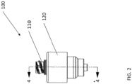
- FIG. 2 is an elevation view of the connector assembly 100 of FIG. 1 , in accordance with various aspects of the present disclosure.
- the connector assembly 100 facilitates a fluid connection with a mating connector.
- the inner connector 110 can be threaded to a mating connector at the upper end and/or the lower end.
- the connector assembly 100 can be utilized with medical tubing.
- the outer connector 120 can be twisted to tighten the threaded connections of the inner connector 110.
- a desired tightness or torque is specified for the connection between the connector assembly 100 and the mating connector.
- clinicians may overtighten connections.
- the disconnecting force for a connection may be higher after disinfecting the connectors.
- Mating connections may be disassembled or removed by twisting the connector assembly 100 in the opposite direction.
- the connector assembly 100 prevents the inner connector 110 from being overtightened to a mating connector. During operation, until the desired torque is reached, rotation of the outer connector 120 rotates the inner connector 110, tightening the mating connection therebetween.
- a clutch mechanism prevents the outer connector 120 from further tightening the inner connector 110. Therefore, after the desired torque is reached, the outer connector 120 may be rotated independently of the inner connector 110.
- the connector assembly 100 can provide feedback or signals to the user that the desired mating torque has been reached. For example, upon rotation of the outer connector 120 after a desired torque is reached, the connector assembly 100 may provide an auditory or tactile signal or feedback (such as a "click").
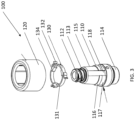
- FIG. 3 is an exploded perspective view of the connector assembly of FIG. 1 , in accordance with various aspects of the present disclosure.
- FIG. 4 is a cross-sectional view of the connector assembly of FIG. 1 , in accordance with various aspects of the present disclosure.
- a clutch 130 permits the connector assembly 100 to limit the amount of torque delivered to the inner connector 110 from the outer connector 120.
- the clutch 130 is rotatably coupled with the inner connector 110 and releasably engaged with the outer connector 120. Therefore, during operation, the clutch 130 allows the outer connector 120 to rotate the inner connector 110 until a desired maximum torque is achieved.
- the clutch 130 may be disposed between the inner connector 110 and the outer connector 120.
- the clutch 130 is concentrically disposed about the inner connector 110.
- the clutch 130 can be disposed along the tapered outer surface 115 of the inner connector 110.
- the clutch 130 can be axially retained relative to the inner connector 110.
- the clutch 130 can be axially retained in a clutch groove 117 defined by an angled flange 116 formed on the tapered outer surface 115 of the inner connector 110.
- the outer connector 120 can include features to axially retain the clutch 130.
- the angled flange 116 can have an angled surface to facilitate assembly of the clutch 130 onto the inner connector 110.
- the clutch 130 can receive rotational torque from the outer connector 120. Further, as illustrated, the clutch teeth 132 extend from an outer surface 131 of the clutch 130 to interface with an inner profile of the outer connector 120. The interface of the clutch teeth 132 with the outer connector 120 allows for torque to be transferred to the clutch 130.
- the outer connector 120 is disposed about the inner connector 110 and the clutch 130.
- the outer connector 120 is concentrically disposed about the inner connector 110 and the clutch 130.
- the outer connector 120 is axially retained relative to the inner connector 110.
- the outer connector 120 can snap fit over the angled flange 116 of the inner connector 110 to axially retain the outer connector 120 relative to the inner connector 110.
- the clutch 130 is rotationally coupled with the inner connector 110 to permit the clutch 130 and the inner connector 110 to rotate together.
- the clutch 130 transfers rotational torque to the inner connector 110 via dogs or features 134 formed on the inner surface of the clutch 130 that engage with the outer surface of the inner connector 110.
- the features 134 of the clutch 130 engage with the slots or channels 118 formed in the tapered outer surface 115 of the inner connector 110. Therefore, during operation, torque from the outer connector 120 is transferred to the inner connector 110 via the clutch 130 to rotate the inner connector 110 relative to any mating connectors.
- the inner connector 110 includes an upper threaded portion 112 and a lower threaded portion 114.
- the upper threaded portion 112 and/or the lower threaded portion 114 can be tightened.
- the threaded surface 113 of the upper threaded portion 112 can be tightened into a mating connector at a desired torque or until the upper threaded portion 112 bottoms out against the mating connector.
- the lower threaded portion 114 can be tightened into a mating connector at a desired torque or until the lower threaded portion 114 bottoms out against the mating connector.
- the outer connector 120 can rotate the inner connector 110 until the predetermined maximum torque is achieved.
- the clutch teeth 132 can disengage from the outer connector 120, permitting the outer connector 120 to spin without tightening the inner connector 110.
- the number of clutch teeth 132 in engagement with the outer connector 120 can determine the maximum torque that can be imparted from the outer connector 120 to the inner connector 110 prior to disengaging the outer connector 120.
- the clutch 130 can include more clutch teeth 132 to allow the outer connector 120 to impart more torque to the inner connector 110, while in some embodiments, the clutch 130 can include fewer clutch teeth 132 to allow the outer connector 120 to impart less torque to the inner connector 110.
- the clutch 130 can include one clutch tooth 132, three clutch teeth 132, five clutch teeth 132, or any other suitable number of clutch teeth 132.
- the clutch 130 can permit the outer connector 120 to loosen the inner connector 110 from any mating connectors.
- the clutch 130 and the outer connector 120 may interface to limit loosening torque.
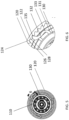
- FIG. 5 is a bottom view of the connector assembly of FIG. 1 , in accordance with various aspects of the present disclosure.
- FIG. 6 is a detail view of the connector assembly of FIG. 5 , in accordance with various aspects of the present disclosure.
- clutch teeth 132 releasably engage against the connector profile 122 of the outer connector 120 to receive or transfer torque from the outer connector 120.
- the outer connector 120 is rotated, thereby rotating the connector profile 122.
- the rotation of the connector profile 122 transmits torque to the clutch teeth 132 and thereby to the inner connector 110.
- the outer connector 120 can continue to provide torque to or otherwise rotate the inner connector 110 as long as the clutch teeth 132 remain in engagement with the connector profile 122.
- the clutch teeth 132 extend radially outward toward the connector profile 122. As shown, the clutch teeth 132 are outwardly biased to maintain engagement with the connector profile 122. In some embodiments, the clutch teeth 132 are resiliently or elastically biased toward the connector profile 122. In some applications, the biasing force of the clutch teeth 132 can be modified by selecting the material, thickness, depth, and other characteristics of the clutch teeth 132 and the clutch 130. Optionally, the angle or geometry of the bend 133 of the clutch teeth 132 can be modified to adjust the biasing force of the clutch teeth.
- the connector profile 122 includes a plurality of engagement features 124 that can transfer rotational force from the outer connector 120 to the engaged clutch teeth 132 in a tangent direction to provide torque to the inner connector 110 and/or force in a radial direction to urge the clutch teeth 132 inwardly and out of engagement with the connector profile 122.
- an engagement feature 124 that transfers rotational force from the outer connector 120 to a clutch tooth 132 in a primarily tangential direction will transfer proportionally more torque than inward radial force to a clutch tooth 132 compared to an engagement feature 124 that transfers rotational force from the outer connector 120 to the clutch tooth 132 in a primarily radial direction (the engagement feature 124 extending primarily tangent to the outer connector 120), which may transfer less torque and more inward radial force to the clutch tooth 132.
- the engagement features 124 can include a combination tangent and radial components to control the proportion of torque that is transferred from the outer connector 120 to the inner connector 110 and the amount of inward radial force that is applied to the clutch teeth 132.
- the clutch teeth 132 are disengaged from the outer connector 120 and allow the outer connector 120 to rotate relative to the inner connector 110, limiting torque transferred to the inner connector 110.
- the disengaged clutch teeth 132 may provide an audible and/or tactile signal to the user.
- the amount of torque that is applied to the inner connector 110 prior to disengaging the clutch teeth 132 can be controlled.
- the relative angle of the engagement features 124 can be adjusted to have a higher operational torque limit or a lower operational torque limit.
- the connector assembly 100 can provide different torque limits for tightening and loosening.
- the connector assembly 100 may provide a lower torque limit for tightening the connector assembly 100 and a higher torque limit for loosening the connector assembly 100.
- the engagement features 124 may be asymmetric. As shown, the profile on the leading side 126 of the engagement feature 124 may differ from the profile on the trailing side 128 of the engagement feature 124. In some embodiments, the leading side 126 may allow for less torque to be imparted in the tightening direction (the leading side 126 extending relatively tangent to the outer connector 120) while the trailing side 128 may allow for greater torque to be imparted in the loosening direction (the trailing side 128 extending relatively normal to the outer connector 120).
- the engagement features 124 can include varying geometric features.
- the engagement features 124 can be rounded or angular to facilitate or inhibit the clutch teeth 132 to disengaging from the connector profile 122.
- complimentary geometric features of the tooth profile 135 of the clutch tooth 132 can be altered to engage with the engagement features 124.
- a phrase such as an "aspect” does not imply that such aspect is essential to the subject technology or that such aspect applies to all configurations of the subject technology.
- a disclosure relating to an aspect may apply to all configurations, or one or more configurations.
- An aspect may provide one or more examples.
- a phrase such as an aspect may refer to one or more aspects and vice versa.
- a phrase such as an "embodiment” does not imply that such embodiment is essential to the subject technology or that such embodiment applies to all configurations of the subject technology.
- a disclosure relating to an embodiment may apply to all embodiments, or one or more embodiments.
- An embodiment may provide one or more examples.
- a phrase such an embodiment may refer to one or more embodiments and vice versa.
- a phrase such as a "configuration” does not imply that such configuration is essential to the subject technology or that such configuration applies to all configurations of the subject technology.
- a disclosure relating to a configuration may apply to all configurations, or one or more configurations.
- a configuration may provide one or more examples.
- a phrase such a configuration may refer to one or more configurations and vice versa.
- Coupled may refer to being directly coupled. In another aspect, the term “coupled” or the like may refer to being indirectly coupled.
- top should be understood as referring to an arbitrary frame of reference, rather than to the ordinary gravitational frame of reference.
- a top surface, a bottom surface, a front surface, and a rear surface may extend upwardly, downwardly, diagonally, or horizontally in a gravitational frame of reference.
Landscapes
- Engineering & Computer Science (AREA)
- Health & Medical Sciences (AREA)
- General Engineering & Computer Science (AREA)
- Heart & Thoracic Surgery (AREA)
- Mechanical Engineering (AREA)
- Anesthesiology (AREA)
- Hematology (AREA)
- Life Sciences & Earth Sciences (AREA)
- Animal Behavior & Ethology (AREA)
- General Health & Medical Sciences (AREA)
- Public Health (AREA)
- Veterinary Medicine (AREA)
- Biomedical Technology (AREA)
- Pulmonology (AREA)
- Infusion, Injection, And Reservoir Apparatuses (AREA)
- One-Way And Automatic Clutches, And Combinations Of Different Clutches (AREA)
- Details Of Connecting Devices For Male And Female Coupling (AREA)
Abstract
Description
- The present disclosure generally relates to connectors, and, in particular, to torque limiting connectors.
- Medical treatments often include the infusion of a medical fluid (e.g., a saline solution or a liquid medication) to patients using an intravenous (IV) catheter that is connected though an arrangement of flexible tubing and fittings, commonly referred to as an "IV set," to a source of fluid, for example, an IV bag. Often, tubing, syringes, needles and other medical equipment are made with threaded connectors and/or a universal luer conical fitting that may be tightened to make it leak-free.
- In some applications, overtightened connections may be difficult or impossible to remove by hand.
- The disclosed subject matter relates to infusion disposables. In certain embodiments, a torque limiting connector is disclosed that comprises an outer connector comprising a profile disposed on an inner surface of the outer connector; an inner connector disposed within the outer connector, the inner connector comprising: an upper threaded portion; and a lower threaded portion; and a clutch disposed around and rotationally coupled to the inner connector, the clutch comprising a plurality of clutch teeth extending from an outer surface of the clutch, wherein the plurality of clutch teeth are outwardly biased to be releasably engaged with the profile of the outer connector, wherein the plurality of clutch teeth are configured to transfer an operational torque from the outer connector to the inner connector when the operational torque is below a torque limit, and the plurality of clutch teeth are forced inward to disengage the profile of the outer connector and prevent transfer of the operational torque when the operational torque exceeds the torque limit.
- In certain embodiments, a torque limiting connector is disclosed that comprises an outer connector comprising a profile disposed on an inner surface of the outer connector; an inner connector disposed within the outer connector, the inner connector comprising: an upper threaded portion; and a lower threaded portion; and a clutch disposed around and rotationally coupled to the inner connector, the clutch comprising a plurality of clutch teeth extending from an outer surface of the clutch, wherein the plurality of clutch teeth are outwardly biased to be releasably engaged with the profile of the outer connector, wherein the plurality of clutch teeth are configured to permit the outer connector to rotate the inner connector when an operational torque is below a torque limit, and the plurality of clutch teeth are forced inward to disengage the profile of the outer connector and permit rotation of the outer connector relative to the inner connector when the operational torque exceeds the torque limit.
- In certain embodiments, a method to tighten a connection is disclosed that comprises threadedly engaging a first connector with a second connector; rotating an outer connector of the first connector at an operational torque below a connection torque limit; and rotating an inner connector of the first connector via the rotation of the outer connector, wherein a clutch rotationally engages the inner connector and the outer connector.
- It is understood that various configurations of the subject technology will become readily apparent to those skilled in the art from the disclosure, wherein various configurations of the subject technology are shown and described by way of illustration. As will be realized, the subject technology is capable of other and different configurations and its several details are capable of modification in various other respects, all without departing from the scope of the subject technology. Accordingly, the summary, drawings and detailed description are to be regarded as illustrative in nature and not as restrictive.
- The accompanying drawings, which are included to provide further understanding and are incorporated in and constitute a part of this specification, illustrate disclosed embodiments and together with the description serve to explain the principles of the disclosed embodiments. In the drawings:
- FIG. l is a perspective view of a connector assembly, in accordance with various aspects of the present disclosure.
-
FIG. 2 is an elevation view of the connector assembly ofFIG. 1 , in accordance with various aspects of the present disclosure. -
FIG. 3 is an exploded perspective view of the connector assembly ofFIG. 1 , in accordance with various aspects of the present disclosure. -
FIG. 4 is a cross-sectional view of the connector assembly ofFIG. 1 , in accordance with various aspects of the present disclosure. -
FIG. 5 is a bottom view of the connector assembly ofFIG. 1 , in accordance with various aspects of the present disclosure. -
FIG. 6 is a detail view of the connector assembly ofFIG. 5 , in accordance with various aspects of the present disclosure. - The disclosed torque limiting connector incorporates a two-part connector with a clutch. The clutch can be disposed between the inner connector and the outer connector to limit torque to the inner connector. By limiting torque to the inner connector, overtightening of connectors can be prevented, preventing damage to connectors and simplifying removal.
- The detailed description set forth below is intended as a description of various configurations of the subject technology and is not intended to represent the only configurations in which the subject technology may be practiced. The detailed description includes specific details for the purpose of providing a thorough understanding of the subject technology. However, it will be apparent to those skilled in the art that the subject technology may be practiced without these specific details. In some instances, well-known structures and components are shown in block diagram form in order to avoid obscuring the concepts of the subject technology. Like components are labeled with identical element numbers for ease of understanding. Reference numbers may have letter suffixes appended to indicate separate instances of a common element while being referred to genetically by the same number without a suffix letter.
- While the following description is directed to the connection of medical fittings for the administration of medical fluid using the disclosed torque limiting connector, it is to be understood that this description is only an example of usage and does not limit the scope of the claims. Various aspects of the disclosed torque limiting connector may be used in any application where it is desirable to provide for the connection of various tubing and fittings without overtightening.
- The disclosed torque limiting connector overcomes several challenges discovered with respect to certain conventional connectors. One challenge with certain conventional connectors is that threaded connectors may be easily overtightened if the engagement surfaces are wet, such as from a disinfectant. Further, clinicians may overtighten conventional connectors to prevent leaks. Because overtightened connectors may require increased (up to three times greater) disconnection force, necessitating the use of mechanical aids such as forceps or pliers, or the replacement of the connected catheter and/or tubing sets, the use of conventional connectors is undesirable.
- Therefore, in accordance with the present disclosure, it is advantageous to provide a torque limiting connector as described herein that eliminates or substantially reduces potential overtightening of the connector. The disclosed torque limiting connector provides an intermediate clutch that permits tightening of the connector, while preventing overtightening of the connector.
- An example of a torque limiting connector that prevents overtightening is now described.
-
FIG. 1 is a perspective view of aconnector assembly 100, in accordance with various aspects of the present disclosure.FIG. 2 is an elevation view of theconnector assembly 100 ofFIG. 1 , in accordance with various aspects of the present disclosure. With reference toFIGS. 1 and2 , theconnector assembly 100 facilitates a fluid connection with a mating connector. In the depicted example, theinner connector 110 can be threaded to a mating connector at the upper end and/or the lower end. For example, theconnector assembly 100 can be utilized with medical tubing. - To tighten the
connector assembly 100 to a mating connector, theouter connector 120 can be twisted to tighten the threaded connections of theinner connector 110. In some applications, a desired tightness or torque is specified for the connection between theconnector assembly 100 and the mating connector. However, during use, clinicians may overtighten connections. For example, the disconnecting force for a connection may be higher after disinfecting the connectors. Mating connections may be disassembled or removed by twisting theconnector assembly 100 in the opposite direction. - Advantageously, the
connector assembly 100 prevents theinner connector 110 from being overtightened to a mating connector. During operation, until the desired torque is reached, rotation of theouter connector 120 rotates theinner connector 110, tightening the mating connection therebetween. - However, after the desired torque is reached, a clutch mechanism prevents the
outer connector 120 from further tightening theinner connector 110. Therefore, after the desired torque is reached, theouter connector 120 may be rotated independently of theinner connector 110. - In addition to preventing overtightening of the
inner connector 110, theconnector assembly 100 can provide feedback or signals to the user that the desired mating torque has been reached. For example, upon rotation of theouter connector 120 after a desired torque is reached, theconnector assembly 100 may provide an auditory or tactile signal or feedback (such as a "click"). -
FIG. 3 is an exploded perspective view of the connector assembly ofFIG. 1 , in accordance with various aspects of the present disclosure.FIG. 4 is a cross-sectional view of the connector assembly ofFIG. 1 , in accordance with various aspects of the present disclosure. With reference toFIGS. 3 and4 , aclutch 130 permits theconnector assembly 100 to limit the amount of torque delivered to theinner connector 110 from theouter connector 120. - In the depicted example, the
clutch 130 is rotatably coupled with theinner connector 110 and releasably engaged with theouter connector 120. Therefore, during operation, theclutch 130 allows theouter connector 120 to rotate theinner connector 110 until a desired maximum torque is achieved. - As shown, the
clutch 130 may be disposed between theinner connector 110 and theouter connector 120. In some embodiments, theclutch 130 is concentrically disposed about theinner connector 110. For example, the clutch 130 can be disposed along the taperedouter surface 115 of theinner connector 110. Optionally, the clutch 130 can be axially retained relative to theinner connector 110. For example, the clutch 130 can be axially retained in aclutch groove 117 defined by anangled flange 116 formed on the taperedouter surface 115 of theinner connector 110. In some embodiments, theouter connector 120 can include features to axially retain the clutch 130. Theangled flange 116 can have an angled surface to facilitate assembly of the clutch 130 onto theinner connector 110. - In the depicted example, the clutch 130 can receive rotational torque from the
outer connector 120. Further, as illustrated, theclutch teeth 132 extend from anouter surface 131 of the clutch 130 to interface with an inner profile of theouter connector 120. The interface of theclutch teeth 132 with theouter connector 120 allows for torque to be transferred to the clutch 130. - As illustrated, the
outer connector 120 is disposed about theinner connector 110 and the clutch 130. Optionally, theouter connector 120 is concentrically disposed about theinner connector 110 and the clutch 130. In some embodiments, theouter connector 120 is axially retained relative to theinner connector 110. For example, theouter connector 120 can snap fit over theangled flange 116 of theinner connector 110 to axially retain theouter connector 120 relative to theinner connector 110. - During operation, to transfer torque from the clutch 130 to the
inner connector 110, the clutch 130 is rotationally coupled with theinner connector 110 to permit the clutch 130 and theinner connector 110 to rotate together. In the depicted example, the clutch 130 transfers rotational torque to theinner connector 110 via dogs or features 134 formed on the inner surface of the clutch 130 that engage with the outer surface of theinner connector 110. In some embodiments, thefeatures 134 of the clutch 130 engage with the slots orchannels 118 formed in the taperedouter surface 115 of theinner connector 110. Therefore, during operation, torque from theouter connector 120 is transferred to theinner connector 110 via the clutch 130 to rotate theinner connector 110 relative to any mating connectors. - In the depicted example, the
inner connector 110 includes an upper threadedportion 112 and a lower threadedportion 114. By rotating theinner connector 110, the upper threadedportion 112 and/or the lower threadedportion 114 can be tightened. For example, the threadedsurface 113 of the upper threadedportion 112 can be tightened into a mating connector at a desired torque or until the upper threadedportion 112 bottoms out against the mating connector. Similarly, the lower threadedportion 114 can be tightened into a mating connector at a desired torque or until the lower threadedportion 114 bottoms out against the mating connector. As previously described, theouter connector 120 can rotate theinner connector 110 until the predetermined maximum torque is achieved. - During operation, after the maximum torque is achieved, the
clutch teeth 132 can disengage from theouter connector 120, permitting theouter connector 120 to spin without tightening theinner connector 110. In some embodiments, the number ofclutch teeth 132 in engagement with theouter connector 120 can determine the maximum torque that can be imparted from theouter connector 120 to theinner connector 110 prior to disengaging theouter connector 120. For example, the clutch 130 can include moreclutch teeth 132 to allow theouter connector 120 to impart more torque to theinner connector 110, while in some embodiments, the clutch 130 can include fewerclutch teeth 132 to allow theouter connector 120 to impart less torque to theinner connector 110. By way of example, the clutch 130 can include oneclutch tooth 132, threeclutch teeth 132, fiveclutch teeth 132, or any other suitable number ofclutch teeth 132. - Similarly, the clutch 130 can permit the
outer connector 120 to loosen theinner connector 110 from any mating connectors. The clutch 130 and theouter connector 120 may interface to limit loosening torque. -
FIG. 5 is a bottom view of the connector assembly ofFIG. 1 , in accordance with various aspects of the present disclosure.FIG. 6 is a detail view of the connector assembly ofFIG. 5 , in accordance with various aspects of the present disclosure. With reference toFIGS. 5 and 6 ,clutch teeth 132 releasably engage against theconnector profile 122 of theouter connector 120 to receive or transfer torque from theouter connector 120. - During operation, the
outer connector 120 is rotated, thereby rotating theconnector profile 122. The rotation of theconnector profile 122 transmits torque to theclutch teeth 132 and thereby to theinner connector 110. Theouter connector 120 can continue to provide torque to or otherwise rotate theinner connector 110 as long as theclutch teeth 132 remain in engagement with theconnector profile 122. - In the depicted example, the
clutch teeth 132 extend radially outward toward theconnector profile 122. As shown, theclutch teeth 132 are outwardly biased to maintain engagement with theconnector profile 122. In some embodiments, theclutch teeth 132 are resiliently or elastically biased toward theconnector profile 122. In some applications, the biasing force of theclutch teeth 132 can be modified by selecting the material, thickness, depth, and other characteristics of theclutch teeth 132 and the clutch 130. Optionally, the angle or geometry of thebend 133 of theclutch teeth 132 can be modified to adjust the biasing force of the clutch teeth. - As illustrated, the
connector profile 122 includes a plurality of engagement features 124 that can transfer rotational force from theouter connector 120 to the engagedclutch teeth 132 in a tangent direction to provide torque to theinner connector 110 and/or force in a radial direction to urge theclutch teeth 132 inwardly and out of engagement with theconnector profile 122. For example, anengagement feature 124 that transfers rotational force from theouter connector 120 to aclutch tooth 132 in a primarily tangential direction (theengagement feature 124 extending primarily normal to the outer connector 120) will transfer proportionally more torque than inward radial force to aclutch tooth 132 compared to anengagement feature 124 that transfers rotational force from theouter connector 120 to theclutch tooth 132 in a primarily radial direction (theengagement feature 124 extending primarily tangent to the outer connector 120), which may transfer less torque and more inward radial force to theclutch tooth 132. In some embodiments, the engagement features 124 can include a combination tangent and radial components to control the proportion of torque that is transferred from theouter connector 120 to theinner connector 110 and the amount of inward radial force that is applied to theclutch teeth 132. - During operation, when the inward radial force imparted on the
clutch teeth 132 by the engagement features 124 overcomes the outward biasing force maintaining theclutch teeth 132 in engagement with theconnector profile 122, theclutch teeth 132 are disengaged from theouter connector 120 and allow theouter connector 120 to rotate relative to theinner connector 110, limiting torque transferred to theinner connector 110. Optionally, the disengagedclutch teeth 132 may provide an audible and/or tactile signal to the user. - By modifying geometric and material properties of the engagement features 124 and the
clutch teeth 132, the amount of torque that is applied to theinner connector 110 prior to disengaging theclutch teeth 132 can be controlled. For example, the relative angle of the engagement features 124 can be adjusted to have a higher operational torque limit or a lower operational torque limit. - In some embodiments, the
connector assembly 100 can provide different torque limits for tightening and loosening. For example, theconnector assembly 100 may provide a lower torque limit for tightening theconnector assembly 100 and a higher torque limit for loosening theconnector assembly 100. - In the depicted example, the engagement features 124 may be asymmetric. As shown, the profile on the leading
side 126 of theengagement feature 124 may differ from the profile on the trailingside 128 of theengagement feature 124. In some embodiments, the leadingside 126 may allow for less torque to be imparted in the tightening direction (the leadingside 126 extending relatively tangent to the outer connector 120) while the trailingside 128 may allow for greater torque to be imparted in the loosening direction (the trailingside 128 extending relatively normal to the outer connector 120). - Optionally, the engagement features 124 can include varying geometric features. For example, the engagement features 124 can be rounded or angular to facilitate or inhibit the
clutch teeth 132 to disengaging from theconnector profile 122. Similarly, complimentary geometric features of thetooth profile 135 of theclutch tooth 132 can be altered to engage with the engagement features 124. - The present disclosure is provided to enable any person skilled in the art to practice the various aspects described herein. The disclosure provides various examples of the subject technology, and the subject technology is not limited to these examples. Various modifications to these aspects will be readily apparent to those skilled in the art, and the generic principles defined herein may be applied to other aspects.
- A reference to an element in the singular is not intended to mean "one and only one" unless specifically so stated, but rather "one or more." Unless specifically stated otherwise, the term "some" refers to one or more. Pronouns in the masculine (e.g., his) include the feminine and neuter gender (e.g., her and its) and vice versa. Headings and subheadings, if any, are used for convenience only and do not limit the invention.
- The word "exemplary" is used herein to mean "serving as an example or illustration." Any aspect or design described herein as "exemplary" is not necessarily to be construed as preferred or advantageous over other aspects or designs. In one aspect, various alternative configurations and operations described herein may be considered to be at least equivalent.
- A phrase such as an "aspect" does not imply that such aspect is essential to the subject technology or that such aspect applies to all configurations of the subject technology. A disclosure relating to an aspect may apply to all configurations, or one or more configurations. An aspect may provide one or more examples. A phrase such as an aspect may refer to one or more aspects and vice versa. A phrase such as an "embodiment" does not imply that such embodiment is essential to the subject technology or that such embodiment applies to all configurations of the subject technology. A disclosure relating to an embodiment may apply to all embodiments, or one or more embodiments. An embodiment may provide one or more examples. A phrase such an embodiment may refer to one or more embodiments and vice versa. A phrase such as a "configuration" does not imply that such configuration is essential to the subject technology or that such configuration applies to all configurations of the subject technology. A disclosure relating to a configuration may apply to all configurations, or one or more configurations. A configuration may provide one or more examples. A phrase such a configuration may refer to one or more configurations and vice versa.
- In one aspect, unless otherwise stated, all measurements, values, ratings, positions, magnitudes, sizes, and other specifications that are set forth in this specification, including in the claims that follow, are approximate, not exact. In one aspect, they are intended to have a reasonable range that is consistent with the functions to which they relate and with what is customary in the art to which they pertain.
- In one aspect, the term "coupled" or the like may refer to being directly coupled. In another aspect, the term "coupled" or the like may refer to being indirectly coupled.
- Terms such as "top," "bottom," "front," "rear" and the like if used in this disclosure should be understood as referring to an arbitrary frame of reference, rather than to the ordinary gravitational frame of reference. Thus, a top surface, a bottom surface, a front surface, and a rear surface may extend upwardly, downwardly, diagonally, or horizontally in a gravitational frame of reference.
- Various items may be arranged differently (e.g., arranged in a different order, or partitioned in a different way) all without departing from the scope of the subject technology. All structural and functional equivalents to the elements of the various aspects described throughout this disclosure that are known or later come to be known to those of ordinary skill in the art are expressly incorporated herein by reference and are intended to be encompassed by the claims. Moreover, nothing disclosed herein is intended to be dedicated to the public regardless of whether such disclosure is explicitly recited in the claims. No claim element is to be construed under the provisions of 35 U.S.C. §112, sixth paragraph, unless the element is expressly recited using the phrase "means for" or, in the case of a method claim, the element is recited using the phrase "step for." Furthermore, to the extent that the term "include," "have," or the like is used, such term is intended to be inclusive in a manner similar to the term "comprise" as "comprise" is interpreted when employed as a transitional word in a claim.
- The Title, Background, Summary, Brief Description of the Drawings and Abstract of the disclosure are hereby incorporated into the disclosure and are provided as illustrative examples of the disclosure, not as restrictive descriptions. It is submitted with the understanding that they will not be used to limit the scope or meaning of the claims. In addition, in the Detailed Description, it can be seen that the description provides illustrative examples and the various features are grouped together in various embodiments for the purpose of streamlining the disclosure. This method of disclosure is not to be interpreted as reflecting an intention that the claimed subject matter requires more features than are expressly recited in each claim. Rather, as the following claims reflect, inventive subject matter lies in less than all features of a single disclosed configuration or operation. The following claims are hereby incorporated into the Detailed Description, with each claim standing on its own as a separately claimed subject matter.
- The claims are not intended to be limited to the aspects described herein, but is to be accorded the full scope consistent with the language claims and to encompass all legal equivalents. Notwithstanding, none of the claims are intended to embrace subject matter that fails to satisfy the requirement of 35 U.S.C. §101, 102, or 103, nor should they be interpreted in such a way.
- The description discloses the following concepts:
- 1. A torque limiting connector, comprising:
- an outer connector comprising a profile disposed on an inner surface of the outer connector;
- an inner connector disposed within the outer connector, the inner connector comprising: an upper threaded portion; and
- a lower threaded portion; and
- a clutch disposed around and rotationally coupled to the inner connector, the clutch comprising a plurality of clutch teeth extending from an outer surface of the clutch, wherein the plurality of clutch teeth are outwardly biased to be releasably engaged with the profile of the outer connector,
- wherein the plurality of clutch teeth are configured to transfer an operational torque from the outer connector to the inner connector when the operational torque is below a torque limit, and the plurality of clutch teeth are forced inward to disengage the profile of the outer connector and prevent transfer of the operational torque when the operational torque exceeds the torque limit.
- 2. The torque limiting connector of concept 1, wherein the clutch is concentrically disposed about the inner connector.
- 3. The torque limiting connector of concept 1, the clutch further comprising a plurality of clutch features, wherein the clutch features engage a plurality of channels formed in the inner connector to rotationally couple the clutch and the inner connector.
- 4. The torque limiting connector of concept 1, the inner connector further comprising an angled flange configured to axially retain the clutch.
- 5. The torque limiting connector of concept 1, wherein the plurality of clutch teeth comprises three clutch teeth.
- 6. The torque limiting connector of concept 1, wherein the profile comprises a plurality of engagement features.
- 7. The torque limiting connector of
concept 6, wherein each of the plurality of engagement features is asymmetric. - 8. The torque limiting connector of concept 7, wherein each of the plurality of engagement features comprises a leading side and a trailing side, wherein the leading side comprises a rounded geometry and the trailing side comprises an angular geometry.
- 9. The torque limiting connector of concept 1, wherein the clutch and the outer connector emit an audible signal when the operational torque exceeds the torque limit.
- 10. The torque limiting connector of concept 1, wherein the clutch and the outer connector emit a tactile signal when the operational torque exceeds the torque limit.
- 11. A torque limiting connector, comprising:
- an outer connector comprising a profile disposed on an inner surface of the outer connector;
- an inner connector disposed within the outer connector, the inner connector comprising: an upper threaded portion; and
- a lower threaded portion; and
- a clutch disposed around and rotationally coupled to the inner connector, the clutch comprising a plurality of clutch teeth extending from an outer surface of the clutch, wherein the plurality of clutch teeth are outwardly biased to be releasably engaged with the profile of the outer connector,
- wherein the plurality of clutch teeth are configured to permit the outer connector to rotate the inner connector when an operational torque is below a torque limit, and the plurality of clutch teeth are forced inward to disengage the profile of the outer connector and permit rotation of the outer connector relative to the inner connector when the operational torque exceeds the torque limit.
- 12. The torque limiting connector of concept 11, the clutch further comprising a plurality of clutch features, wherein the clutch features engage a plurality of channels formed in the inner connector to rotationally couple the clutch and the inner connector.
- 13. The torque limiting connector of concept 11, the inner connector further comprising an angled flange configured to axially retain the clutch.
- 14. The torque limiting connector of concept 11, wherein the profile comprises a plurality of engagement features.
- 15. The torque limiting connector of concept 14, wherein each of the plurality of engagement features is asymmetric.
- 16. The torque limiting connector of concept 15, wherein each of the plurality of engagement features comprises a leading side and a trailing side, wherein the leading side comprises a rounded geometry and the trailing side comprises an angular geometry.
- 17. The torque limiting connector of concept 11, wherein the clutch and the outer connector emit an audible signal when the operational torque exceeds the torque limit.
- 18. The torque limiting connector of concept 11, wherein the clutch and the outer connector emit a tactile signal when the operational torque exceeds the torque limit.
- 19. A method to tighten a connection, the method comprising:
- threadedly engaging a first connector with a second connector;
- rotating an outer connector of the first connector at an operational torque below a connection torque limit; and
- rotating an inner connector of the first connector via the rotation of the outer connector, wherein
- a clutch rotationally engages the inner connector and the outer connector.
- 20. The method of concept 19, further comprising:
- rotating the outer connector at the operational torque exceeding the connection torque limit; and
- rotating the outer connector relative to the inner connector, wherein the clutch disengages the outer connector from the inner connector.
Claims (15)
- A torque limiting connector, comprising:an outer connector comprising a profile disposed on an inner surface of the outer connector, and an inner connector disposed within the outer connector, the inner connector comprising an upper threaded portion, a lower threaded portion, and a flange extending radially outward in direction away from an outer surface of the inner connector; anda clutch disposed between the inner and outer connectors, and axially aligned between the lower threaded portion and the flange, wherein the clutch extends around the outer surface of the inner connector and, is rotationally coupled with the inner connector, the clutch comprising a plurality of clutch teeth extending from an outer surface of the clutch and outwardly biased to be releasably engaged with the profile of the outer connector,wherein the plurality of clutch teeth are configured to transfer an operational torque from the outer connector to the inner connector when the operational torque is below a torque limit, and the plurality of clutch teeth are forced inward to disengage the profile of the outer connector and resist transfer of the operational torque from the outer connector to the inner connector when the operational torque exceeds the torque limit.
- The torque limiting connector of Claim 1, wherein the clutch is positioned between the flange and the lower threaded portion of the inner connector.
- The torque limiting connector of Claim 1, wherein a portion of the outer connector is positioned between the flange and the lower threaded portion of the inner connector, such that an engagement of the portion of the outer connector against the flange resists axial movement of the outer connector relative to the inner connector.
- The torque limiting connector of Claim 1, wherein the outer connector comprises a snap fit over the flange of the inner connector.
- The torque limiting connector of Claim 1, wherein the clutch is concentrically disposed about the inner connector.
- The torque limiting connector of Claim 1, wherein the plurality of clutch teeth comprises three clutch teeth.
- The torque limiting connector of Claim 1, wherein the profile comprises a plurality of engagement features.
- The torque limiting connector of Claim 7, wherein each of the plurality of engagement features is asymmetric.
- The torque limiting connector of Claim 8, wherein each of the plurality of engagement features comprises a leading side and a trailing side, wherein the leading side comprises a rounded geometry and the trailing side comprises an angular geometry.
- The torque limiting connector of Claim 7, wherein a tooth of the plurality of clutch teeth comprises a convex surface configured to engage against a leading side of each of the plurality of engagement features.
- The torque limiting connector of Claim 7, wherein a tooth of the plurality of clutch teeth comprises a concave surface configured to engage against a trailing side of each of the plurality of engagement features.
- A method of providing a torque limiting connector, the method comprising:providing an outer connector comprising a profile disposed on an inner surface of the outer connector;providing an inner connector disposed within the outer connector, the inner connector comprising an upper threaded portion, a lower threaded portion, and a flange extending radially outward in direction away from an outer surface of the inner connector; anddisposing a clutch between the inner and outer connectors, and between the lower threaded portion and the flange, such that the clutch is rotationally coupled with the inner connector, and a plurality of clutch teeth of the clutch extend from an outer surface of the clutch to engage against the profile of the outer connector;wherein the plurality of clutch teeth are configured to transfer an operational torque from the outer connector to the inner connector when the operational torque is below a torque limit, and to bias radially inward toward the inner connector to disengage the profile of the outer connector and prevent transfer of the operational torque when the operational torque exceeds the torque limit.
- The method of Claim 12, wherein disposing the clutch between the inner and outer connectors comprises any of inserting the inner connector through the clutch in a direction from the upper threaded portion toward the lower threaded portion such that the clutch is concentrically disposed about the inner connector, and moving the outer connector over the clutch in a direction from the upper threaded portion toward the lower threaded portion such that the outer connector is concentrically disposed about the clutch and the inner connector.
- The method of Claim 12, wherein disposing the clutch between the inner and outer connectors comprises inserting the inner connector through the clutch in a direction from the upper threaded portion toward the lower threaded portion until the clutch is positioned between the flange of the inner connector and the lower threaded portion of the inner connector.
- The method of Claim 12, wherein disposing the clutch between the inner and outer connectors comprises inserting the inner connector through the outer connector until a snap fit of the outer connector is positioned between the flange of the inner connector and the lower threaded portion of the inner connector.
Applications Claiming Priority (3)
| Application Number | Priority Date | Filing Date | Title |
|---|---|---|---|
| US16/287,913 US11441611B2 (en) | 2019-02-27 | 2019-02-27 | Torque limiting connector |
| EP20712807.5A EP3931458B1 (en) | 2019-02-27 | 2020-02-26 | Torque limiting connector |
| PCT/US2020/019863 WO2020176601A1 (en) | 2019-02-27 | 2020-02-26 | Torque limiting connector |
Related Parent Applications (2)
| Application Number | Title | Priority Date | Filing Date |
|---|---|---|---|
| EP20712807.5A Division EP3931458B1 (en) | 2019-02-27 | 2020-02-26 | Torque limiting connector |
| EP20712807.5A Division-Into EP3931458B1 (en) | 2019-02-27 | 2020-02-26 | Torque limiting connector |
Publications (2)
| Publication Number | Publication Date |
|---|---|
| EP4414018A2 true EP4414018A2 (en) | 2024-08-14 |
| EP4414018A3 EP4414018A3 (en) | 2024-11-13 |
Family
ID=69846627
Family Applications (2)
| Application Number | Title | Priority Date | Filing Date |
|---|---|---|---|
| EP20712807.5A Active EP3931458B1 (en) | 2019-02-27 | 2020-02-26 | Torque limiting connector |
| EP24185627.7A Pending EP4414018A3 (en) | 2019-02-27 | 2020-02-26 | Torque limiting connector |
Family Applications Before (1)
| Application Number | Title | Priority Date | Filing Date |
|---|---|---|---|
| EP20712807.5A Active EP3931458B1 (en) | 2019-02-27 | 2020-02-26 | Torque limiting connector |
Country Status (8)
| Country | Link |
|---|---|
| US (4) | US11441611B2 (en) |
| EP (2) | EP3931458B1 (en) |
| JP (3) | JP7328343B2 (en) |
| CN (2) | CN113474569B (en) |
| AU (1) | AU2020228621B2 (en) |
| CA (1) | CA3130306A1 (en) |
| MX (1) | MX2021009375A (en) |
| WO (1) | WO2020176601A1 (en) |
Families Citing this family (6)
| Publication number | Priority date | Publication date | Assignee | Title |
|---|---|---|---|---|
| US11441611B2 (en) * | 2019-02-27 | 2022-09-13 | Carefusion 303, Inc. | Torque limiting connector |
| US12000448B2 (en) * | 2019-09-20 | 2024-06-04 | Pacesetter, Inc. | Biostimulator transport system having torque limiter |
| CN115523244B (en) * | 2021-06-25 | 2025-12-26 | 创领心律管理医疗器械(上海)有限公司 | Torque devices and medical device systems for medical equipment |
| US20230015919A1 (en) * | 2021-07-14 | 2023-01-19 | Brasscraft Manufacturing Company | Torque-limiting fastener and coupling |
| EP4695049A2 (en) * | 2023-04-12 | 2026-02-18 | ECA Medical Instruments | Locking devices and mechanisms for torque-limiting devices |
| USD1105422S1 (en) | 2024-02-09 | 2025-12-09 | Icu Medical, Inc. | Medical connector cover |
Family Cites Families (27)
| Publication number | Priority date | Publication date | Assignee | Title |
|---|---|---|---|---|
| US3667307A (en) * | 1968-07-19 | 1972-06-06 | Kienzle Apparate Gmbh | Stepping clutch device |
| FR2499181B1 (en) * | 1981-02-04 | 1986-03-28 | Valeo | TORSION DAMPING DEVICE, IN PARTICULAR A CLUTCH FRICTION, IN PARTICULAR FOR A MOTOR VEHICLE |
| US4570769A (en) * | 1981-11-26 | 1986-02-18 | Kabushiki Kaisha Sankyo Seiki Seisakusho | Ratchet mechanism |
| US5020648A (en) * | 1988-11-14 | 1991-06-04 | Reliable Plastics Engineering Company | Ratchet assembly |
| US5088581A (en) * | 1991-01-30 | 1992-02-18 | Eaton Corporation | One-way clutch |
| US5242154A (en) * | 1991-06-10 | 1993-09-07 | Build-A-Mold Limited | Torque limiter for wheel-lift mechanism |
| JPH0727121A (en) * | 1993-06-30 | 1995-01-27 | Jacobs Japan Inc | Screw for tightening |
| JP2000205293A (en) * | 1999-01-14 | 2000-07-25 | Toyota Autom Loom Works Ltd | Power transmitting mechanism |
| US6589121B1 (en) * | 1999-09-17 | 2003-07-08 | Halo Product Innovations | Fully adjustable torque controller, clutch and brake |
| JP2001343024A (en) * | 2000-03-29 | 2001-12-14 | Toyota Industries Corp | Power transmission mechanism |
| DE10341697B3 (en) * | 2003-09-10 | 2004-10-07 | Felo-Werkzeugfabrik Holland-Letz Gmbh | Screwdriver used as a hand screwdriver comprises couplings each consisting of a locking bushing, a catch bushing and a pressure spring with a pre-tension between the couplings on a toothed casing |
| CN101432559A (en) * | 2006-04-27 | 2009-05-13 | Diba工业公司 | Multi-use torque fitting |
| US20070254744A1 (en) * | 2006-04-27 | 2007-11-01 | Diba Industries, Inc. | Multi-use torque fitting |
| US7878316B2 (en) * | 2007-10-09 | 2011-02-01 | GM Global Technology Operations LLC | High torque one way clutch |
| DE102007051263B4 (en) * | 2007-10-26 | 2010-09-09 | Harting Electronics Gmbh & Co. Kg | Optical connector |
| DE602007001696D1 (en) * | 2007-11-08 | 2009-09-03 | Meco Sa | Winding crown for watch comprising a mechanism with torque coupling |
| US20090133980A1 (en) | 2007-11-28 | 2009-05-28 | Swaim Jason A | Torque-Limiting Connector |
| US7984933B2 (en) * | 2008-02-28 | 2011-07-26 | Diba Industries, Inc. | Multi-use torque fitting and compressible ferrule |
| CN101870282B (en) * | 2009-04-21 | 2012-10-03 | 株式会社东海理化电机制作所 | seat belt retractor |
| CH702924B1 (en) * | 2010-06-03 | 2011-10-14 | Patek Philippe Sa Geneve | Mobile-way clutch, winding mechanism and a timepiece including said mobile. |
| US8888143B2 (en) | 2011-09-23 | 2014-11-18 | Diba Industries, Inc. | Torque limiting fastening assemblies and fluid coupling assemblies including the same |
| US9310008B2 (en) | 2012-03-12 | 2016-04-12 | Idex Health & Science Llc | Torque limited fitting |
| US10098768B2 (en) * | 2014-09-15 | 2018-10-16 | Cook Medical Technologies Llc | Ratchet operated vascular intervention device delivery system |
| US10183158B2 (en) * | 2015-04-02 | 2019-01-22 | Koyo Sangyo Co., Ltd. | Connecting structure for medical use |
| EP3545916B1 (en) | 2017-03-10 | 2022-11-02 | Hangzhou Dinova EP Technology Co., Ltd. | Interventional medical instrument conveying system |
| EP3415194B1 (en) | 2017-04-12 | 2020-01-29 | Koyo Sangyo Co. Ltd. | Connecting structure for medical use |
| US11441611B2 (en) * | 2019-02-27 | 2022-09-13 | Carefusion 303, Inc. | Torque limiting connector |
-
2019
- 2019-02-27 US US16/287,913 patent/US11441611B2/en active Active
-
2020
- 2020-02-26 JP JP2021549959A patent/JP7328343B2/en active Active
- 2020-02-26 AU AU2020228621A patent/AU2020228621B2/en active Active
- 2020-02-26 EP EP20712807.5A patent/EP3931458B1/en active Active
- 2020-02-26 WO PCT/US2020/019863 patent/WO2020176601A1/en not_active Ceased
- 2020-02-26 EP EP24185627.7A patent/EP4414018A3/en active Pending
- 2020-02-26 CN CN202080016625.0A patent/CN113474569B/en active Active
- 2020-02-26 CN CN202410836537.5A patent/CN118564573A/en active Pending
- 2020-02-26 CA CA3130306A patent/CA3130306A1/en active Pending
- 2020-02-26 MX MX2021009375A patent/MX2021009375A/en unknown
-
2022
- 2022-09-09 US US17/941,998 patent/US11767886B2/en active Active
-
2023
- 2023-08-03 JP JP2023126812A patent/JP2023143981A/en active Pending
- 2023-08-14 US US18/449,201 patent/US12092180B2/en active Active
-
2024
- 2024-08-12 US US18/800,491 patent/US20240401650A1/en active Pending
-
2025
- 2025-10-09 JP JP2025170756A patent/JP2025185091A/en active Pending
Also Published As
| Publication number | Publication date |
|---|---|
| EP4414018A3 (en) | 2024-11-13 |
| JP2022521785A (en) | 2022-04-12 |
| EP3931458A1 (en) | 2022-01-05 |
| WO2020176601A1 (en) | 2020-09-03 |
| EP3931458B1 (en) | 2024-10-23 |
| JP2025185091A (en) | 2025-12-18 |
| JP2023143981A (en) | 2023-10-06 |
| US11441611B2 (en) | 2022-09-13 |
| MX2021009375A (en) | 2021-09-10 |
| CN118564573A (en) | 2024-08-30 |
| CA3130306A1 (en) | 2020-09-03 |
| US12092180B2 (en) | 2024-09-17 |
| AU2020228621B2 (en) | 2025-10-09 |
| CN113474569A (en) | 2021-10-01 |
| US20230392650A1 (en) | 2023-12-07 |
| US20240401650A1 (en) | 2024-12-05 |
| US20200271171A1 (en) | 2020-08-27 |
| CN113474569B (en) | 2024-07-02 |
| AU2020228621A1 (en) | 2021-09-16 |
| JP7328343B2 (en) | 2023-08-16 |
| US11767886B2 (en) | 2023-09-26 |
| US20230003262A1 (en) | 2023-01-05 |
| EP3931458C0 (en) | 2024-10-23 |
Similar Documents
| Publication | Publication Date | Title |
|---|---|---|
| US11767886B2 (en) | Torque limiting connector | |
| RU2218950C2 (en) | Connection device usable with medical cannula | |
| US20160339184A1 (en) | Drug Delivery Connectors | |
| AU2012299372C1 (en) | Retractable luer lock fittings | |
| EP1432468A2 (en) | Coupling for medical fluid delivery systems | |
| EP2996761B1 (en) | Mechanical friction enhancement for threaded connection incorporating micro-threads | |
| US12584578B2 (en) | Torsional connector coupling assembly | |
| WO2025117041A1 (en) | Non-disconnecting rotatable connector assembly | |
| WO2010052517A1 (en) | Improved drug container | |
| WO2024233270A1 (en) | Locking connector coupling assembly | |
| JP2026501049A (en) | Luer connectors for vascular access devices | |
| US20260108717A1 (en) | Connection retention assembly | |
| US11986620B2 (en) | Fluid-fitting tool | |
| US20250347372A1 (en) | Fluid hub assembly | |
| WO2024253919A1 (en) | Slit-free safe disconnect |
Legal Events
| Date | Code | Title | Description |
|---|---|---|---|
| PUAI | Public reference made under article 153(3) epc to a published international application that has entered the european phase |
Free format text: ORIGINAL CODE: 0009012 |
|
| STAA | Information on the status of an ep patent application or granted ep patent |
Free format text: STATUS: THE APPLICATION HAS BEEN PUBLISHED |
|
| AC | Divisional application: reference to earlier application |
Ref document number: 3931458 Country of ref document: EP Kind code of ref document: P |
|
| AK | Designated contracting states |
Kind code of ref document: A2 Designated state(s): AL AT BE BG CH CY CZ DE DK EE ES FI FR GB GR HR HU IE IS IT LI LT LU LV MC MK MT NL NO PL PT RO RS SE SI SK SM TR |
|
| REG | Reference to a national code |
Ref country code: DE Ref legal event code: R079 Free format text: PREVIOUS MAIN CLASS: A61M0039100000 Ipc: F16D0007000000 |
|
| PUAL | Search report despatched |
Free format text: ORIGINAL CODE: 0009013 |
|
| AK | Designated contracting states |
Kind code of ref document: A3 Designated state(s): AL AT BE BG CH CY CZ DE DK EE ES FI FR GB GR HR HU IE IS IT LI LT LU LV MC MK MT NL NO PL PT RO RS SE SI SK SM TR |
|
| RIC1 | Information provided on ipc code assigned before grant |
Ipc: A61M 39/10 20060101ALI20241007BHEP Ipc: F16D 7/04 20060101ALI20241007BHEP Ipc: F16D 7/00 20060101AFI20241007BHEP |
|
| STAA | Information on the status of an ep patent application or granted ep patent |
Free format text: STATUS: REQUEST FOR EXAMINATION WAS MADE |
|
| 17P | Request for examination filed |
Effective date: 20250410 |
|
| GRAP | Despatch of communication of intention to grant a patent |
Free format text: ORIGINAL CODE: EPIDOSNIGR1 |
|
| STAA | Information on the status of an ep patent application or granted ep patent |
Free format text: STATUS: GRANT OF PATENT IS INTENDED |
|
| RIC1 | Information provided on ipc code assigned before grant |
Ipc: F16D 7/00 20060101AFI20260326BHEP Ipc: F16D 7/04 20060101ALI20260326BHEP Ipc: A61M 39/10 20060101ALI20260326BHEP |
|
| INTG | Intention to grant announced |
Effective date: 20260407 |