EP4413909A1 - Surface cleaning device and cleaning system - Google Patents
Surface cleaning device and cleaning system Download PDFInfo
- Publication number
- EP4413909A1 EP4413909A1 EP23162653.2A EP23162653A EP4413909A1 EP 4413909 A1 EP4413909 A1 EP 4413909A1 EP 23162653 A EP23162653 A EP 23162653A EP 4413909 A1 EP4413909 A1 EP 4413909A1
- Authority
- EP
- European Patent Office
- Prior art keywords
- dirty water
- water tank
- cleaning device
- surface cleaning
- section
- Prior art date
- Legal status (The legal status is an assumption and is not a legal conclusion. Google has not performed a legal analysis and makes no representation as to the accuracy of the status listed.)
- Withdrawn
Links
Images





Classifications
-
- A—HUMAN NECESSITIES
- A47—FURNITURE; DOMESTIC ARTICLES OR APPLIANCES; COFFEE MILLS; SPICE MILLS; SUCTION CLEANERS IN GENERAL
- A47L—DOMESTIC WASHING OR CLEANING; SUCTION CLEANERS IN GENERAL
- A47L11/00—Machines for cleaning floors, carpets, furniture, walls, or wall coverings
- A47L11/40—Parts or details of machines not provided for in groups A47L11/02 - A47L11/38, or not restricted to one of these groups, e.g. handles, arrangements of switches, skirts, buffers, levers
- A47L11/4013—Contaminants collecting devices, i.e. hoppers, tanks or the like
- A47L11/4016—Contaminants collecting devices, i.e. hoppers, tanks or the like specially adapted for collecting fluids
-
- A—HUMAN NECESSITIES
- A47—FURNITURE; DOMESTIC ARTICLES OR APPLIANCES; COFFEE MILLS; SPICE MILLS; SUCTION CLEANERS IN GENERAL
- A47L—DOMESTIC WASHING OR CLEANING; SUCTION CLEANERS IN GENERAL
- A47L11/00—Machines for cleaning floors, carpets, furniture, walls, or wall coverings
- A47L11/24—Floor-sweeping machines, motor-driven
-
- A—HUMAN NECESSITIES
- A47—FURNITURE; DOMESTIC ARTICLES OR APPLIANCES; COFFEE MILLS; SPICE MILLS; SUCTION CLEANERS IN GENERAL
- A47L—DOMESTIC WASHING OR CLEANING; SUCTION CLEANERS IN GENERAL
- A47L11/00—Machines for cleaning floors, carpets, furniture, walls, or wall coverings
- A47L11/29—Floor-scrubbing machines characterised by means for taking-up dirty liquid
- A47L11/292—Floor-scrubbing machines characterised by means for taking-up dirty liquid having rotary tools
-
- A—HUMAN NECESSITIES
- A47—FURNITURE; DOMESTIC ARTICLES OR APPLIANCES; COFFEE MILLS; SPICE MILLS; SUCTION CLEANERS IN GENERAL
- A47L—DOMESTIC WASHING OR CLEANING; SUCTION CLEANERS IN GENERAL
- A47L11/00—Machines for cleaning floors, carpets, furniture, walls, or wall coverings
- A47L11/29—Floor-scrubbing machines characterised by means for taking-up dirty liquid
- A47L11/30—Floor-scrubbing machines characterised by means for taking-up dirty liquid by suction
- A47L11/302—Floor-scrubbing machines characterised by means for taking-up dirty liquid by suction having rotary tools
-
- A—HUMAN NECESSITIES
- A47—FURNITURE; DOMESTIC ARTICLES OR APPLIANCES; COFFEE MILLS; SPICE MILLS; SUCTION CLEANERS IN GENERAL
- A47L—DOMESTIC WASHING OR CLEANING; SUCTION CLEANERS IN GENERAL
- A47L11/00—Machines for cleaning floors, carpets, furniture, walls, or wall coverings
- A47L11/40—Parts or details of machines not provided for in groups A47L11/02 - A47L11/38, or not restricted to one of these groups, e.g. handles, arrangements of switches, skirts, buffers, levers
- A47L11/4036—Parts or details of the surface treating tools
- A47L11/4041—Roll shaped surface treating tools
-
- A—HUMAN NECESSITIES
- A47—FURNITURE; DOMESTIC ARTICLES OR APPLIANCES; COFFEE MILLS; SPICE MILLS; SUCTION CLEANERS IN GENERAL
- A47L—DOMESTIC WASHING OR CLEANING; SUCTION CLEANERS IN GENERAL
- A47L11/00—Machines for cleaning floors, carpets, furniture, walls, or wall coverings
- A47L11/40—Parts or details of machines not provided for in groups A47L11/02 - A47L11/38, or not restricted to one of these groups, e.g. handles, arrangements of switches, skirts, buffers, levers
- A47L11/4052—Movement of the tools or the like perpendicular to the cleaning surface
- A47L11/4055—Movement of the tools or the like perpendicular to the cleaning surface for lifting the tools to a non-working position
-
- A—HUMAN NECESSITIES
- A47—FURNITURE; DOMESTIC ARTICLES OR APPLIANCES; COFFEE MILLS; SPICE MILLS; SUCTION CLEANERS IN GENERAL
- A47L—DOMESTIC WASHING OR CLEANING; SUCTION CLEANERS IN GENERAL
- A47L11/00—Machines for cleaning floors, carpets, furniture, walls, or wall coverings
- A47L11/40—Parts or details of machines not provided for in groups A47L11/02 - A47L11/38, or not restricted to one of these groups, e.g. handles, arrangements of switches, skirts, buffers, levers
- A47L11/4091—Storing or parking devices, arrangements therefor; Means allowing transport of the machine when it is not being used
-
- A—HUMAN NECESSITIES
- A47—FURNITURE; DOMESTIC ARTICLES OR APPLIANCES; COFFEE MILLS; SPICE MILLS; SUCTION CLEANERS IN GENERAL
- A47L—DOMESTIC WASHING OR CLEANING; SUCTION CLEANERS IN GENERAL
- A47L2201/00—Robotic cleaning machines, i.e. with automatic control of the travelling movement or the cleaning operation
-
- A—HUMAN NECESSITIES
- A47—FURNITURE; DOMESTIC ARTICLES OR APPLIANCES; COFFEE MILLS; SPICE MILLS; SUCTION CLEANERS IN GENERAL
- A47L—DOMESTIC WASHING OR CLEANING; SUCTION CLEANERS IN GENERAL
- A47L2201/00—Robotic cleaning machines, i.e. with automatic control of the travelling movement or the cleaning operation
- A47L2201/02—Docking stations; Docking operations
-
- A—HUMAN NECESSITIES
- A47—FURNITURE; DOMESTIC ARTICLES OR APPLIANCES; COFFEE MILLS; SPICE MILLS; SUCTION CLEANERS IN GENERAL
- A47L—DOMESTIC WASHING OR CLEANING; SUCTION CLEANERS IN GENERAL
- A47L2201/00—Robotic cleaning machines, i.e. with automatic control of the travelling movement or the cleaning operation
- A47L2201/02—Docking stations; Docking operations
- A47L2201/024—Emptying dust or waste liquid containers
Definitions
- the present disclosure relates to a field of cleaning devices, more specifically, to a surface cleaning device and a cleaning system.
- cleaning systems such as cleaning robots may automatically clean ground without human operations, providing convenience for modem life.
- cleaning robots may realize various cleaning functions, such as sweeping and mopping, which may be further divided into dry mopping and wet mopping.
- cleaning robots may also be realized as sweeping robots, mopping robots, sweeping and mopping all-in-one robots, etc.
- different components need to be equipped in cleaning devices.
- a cleaning equipment For example, for sweeping, a cleaning equipment needs to be equipped with a dust box to collect dust; for mopping, a cleaning equipment usually needs to be equipped with a clear water tank and a mop; for mop self-cleaning, a cleaning equipment needs to be further equipped with a dirty water tank to collect dirty water generated during a cleaning process.
- these components need to be cleaned and maintained regularly, which increases burden of users.
- an increase of components causes additional problems. For example, for a cleaning robot equipped with a dirty water tank, it is difficult to seal the dirty water tank because it needs to be opened for recycling dirty water when mopping the floor. However, users may sometimes lift a robot and turn the robot over to check or clean a side brush, a dust suction port, a roller brush, and other components used for sweeping the floor. It is easy to cause dirty water leakage if a dirty water tank is not sealed, and user experience is poor.
- CN217244111U discloses a maintenance station for a cleaning device.
- the maintenance station may use an exhauster to suck cleaned dirty water from the cleaning device into a dirty water bucket disposed on a base of the maintenance station.
- the maintenance station only has a function of sucking dirty water, without a function of automatic dust collection.
- an additional set of an exhauster and an air duct is usually equipped in prior art to collect dust from a dust box of the cleaning device to the base station.
- two sets of suction systems are required in base stations, one for dust collection and the other for dirty water suction, resulting in large volume and high cost of base stations.
- CN212118059U discloses a sealing structure for a dirty water box, in which a dirty water inlet is opened when a dirty water box is put into a groove, and the dirty water inlet is sealed when the dirty water box is moved out of the groove.
- This structure may solve the problem of dirty water leakage when a user takes out the dirty water box to a certain extent, but when the user turns a robot without taking out the dirty water box, the dirty water inlet is open, and dirty water leakage will still occur.
- One of objects of the present disclosure is to provide a surface cleaning device and a cleaning system.
- a sealing structure is disposed at an inlet of a dirty water tank.
- the sealing structure is linked with lifting and lowering of a cleaning component of the surface cleaning device. Therefore, the inlet of the dirty water tank is opened only when a cleaning component is in a lowered state when performing ground work, while at any other time, the cleaning component is in a lifted state, and the inlet of the dirty water tank is thus sealed to effectively prevent dirty water leakage.
- a single exhauster system is used for automatic dust collection and dirty extraction, which reduces volumes and costs of the base station.
- a linkage sealing structure of the dirty water tank may switch states in a dust collection process and a dirty water extraction process accordingly to improve suction efficiencies of the exhauster.
- a surface cleaning device which comprises: a machine body; a cleaning component, installed and connected to the machine body, the cleaning component comprising a cleaning section for cleaning the surface; a dirty water tank with a dirty water tank inlet; and a dirty water tank inlet sealing component for sealing or opening the dirty water tank inlet, which seals the dirty water tank inlet when the cleaning section is lifted, and opens the dirty water tank inlet when the cleaning section is lowered.
- the dirty water tank inlet may only be opened when the surface cleaning device is performing mopping tasks. Otherwise, the dirty water tank inlet may remain sealed. Users rarely lift and turn a surface cleaning device over when the surface cleaning device is performing mopping tasks. Therefore, the present disclosure may effectively prevent water leakage from dirty water tanks and improve user experiences.
- the cleaning section is a cleaning roller
- the cleaning component further comprises a bracket section connected with the cleaning section, and the bracket section is lifted and lowered with lifting and lowering of the cleaning section. In this manner, the cleaning section may be lifted and lowered by lifting and lowering the bracket section.
- the dirty water tank inlet sealing component comprises: a convex rib, fixed on a bracket section; a dirty water tank door which is movably installed at the dirty water tank inlet; and a transmission mechanism, connected between the convex rib and the dirty water tank door for transmitting different forces applied on the dirty water tank door by lifting or lowering the section.
- a linkage between inlet and closing of the dirty water tank inlet and lifting and lowering of the cleaning section is realized.
- the transmission mechanism is an L-type rotating swing rod
- a rotating shaft of the rotating swing rod is fixed on the machine body, wherein a first swing arm of the rotating swing rod contacts the convex rib, and a second swing arm of the rotating swing rod contacts with the dirty water tank door.
- a transfer between the bracket section and the dirty water tank door may be realized by rotating by disposing the L-type rotating swing rod.
- the dirty water tank door is installed with a sealing section on a side facing the dirty water tank inlet.
- the leakproofness of the dirty water tank door may be improved by the sealing section.
- the dirty water tank door is provided with a convex section on a side facing the dirty water tank inlet, which extends from the dirty water tank inlet and contacts a second swing arm of the rotating swing rod.
- the transmission may be further extended to the dirty water tank door in case the rotating swing rod may not reach the dirty water tank door, and a structure of the rotating swing rod may also be kept simple.
- the dirty water tank door is rotatably mounted on an internal side of the dirty water tank inlet through a spring hinge, and the spring hinge is arranged to provide a bias force that causes the dirty water tank door to seal the dirty water tank inlet.
- the dirty water tank inlet may be kept normally closed by the spring hinge.
- a cleaning system has a base station and the surface cleaning device as described in the embodiments of the present disclosure, wherein the surface cleaning device further comprises a dust box; and the base station further comprises: a dirty water bucket, in which a first channel for dirty water entering and a second channel for air discharging are disposed; a dust collection tank, in which a third channel for dust entering and an air outlet for air discharging are disposed; and an exhauster for generating negative pressure, wherein the first channel of the dirty water bucket interfaces with the water outlet of the dirty water tank of the surface cleaning device, the third channel of the dust collection tank interfaces with a dust box of the surface cleaning device, and the second channel of the dirty water bucket and the air outlet of the dust collection tank interface with an air inlet of the exhauster.
- a conventional vacuum pump for dirty water suction is saved, cost of the base station is reduced, and volumes of the base station become more compact by disposing a common exhauster.
- a cross-sectional area of the first channel is smaller than a cross-sectional area of the third channel. In this manner, a dust collection side may obtain a required greater vacuum degree and air volume.
- the cleaning system further comprises a water suction channel switch component, which is used to open or seal a water suction channel comprising the first channel, the second channel, and the dirty water tank of the surface cleaning device.
- the water suction channel may be closed by the water suction channel switch component, thereby significantly improving a vacuum degree and air volume during dust collection.
- the water suction channel switch component is a sealing cover disposed in the first channel or the second channel.
- the water suction channel may be sealed in a simple structure by disposing the sealing cover.
- the water suction channel switch component is the dirty water tank inlet sealing component of the surface cleaning device of the present disclosure. In this manner, opening and closing of the water suction channel may be performed without additional components, further simplifying a structure of the surface cleaning device and reducing its cost.
- the cleaning section is placed in a lifted state when the base station performs a dust collection process of collecting dust from the dust box of the surface cleaning device, and the cleaning section is placed in a lowered state when the base station performs a dirty water suction or self-cleaning process of collecting dirty from the dirty water tank of the surface cleaning device.
- the water suction channel may be opened and closed by controlling states of the cleaning section, and control logics may be effectively combined with maintenance tasks performed by the base station.
- the dirty water bucket of the base station is provided with a water-air separation structure, which is used to separate water from air sucked into the dirty water bucket under the action of the exhauster, so that the separated water remains in the dirty water bucket, and the separated air enters the exhauster through the second channel.
- This water-air separation structure utilizes a principle of gravity and has a simple structure. Also, it ensures that water will not enter the exhauster and cause exhauster failure or noise problems.
- a control method for the surface cleaning device in the present disclosure comprises: controlling the dirty water tank inlet sealing component in a linked manner to seal the dirty water tank inlet of the dirty water tank of the surface cleaning device when the cleaning section of the surface cleaning device is lifted; and controlling the dirty water tank inlet sealing component in a linked manner to open the dirty water tank inlet when the cleaning section is lowered.
- a linkage control between lifting and lowering of the cleaning section of the surface cleaning device and inlet and closing of the dirty water tank inlet may be realized, so as to ensure that the dirty water tank inlet may be sealed without leakage when the surface cleaning device is lifted or turned over, thereby improving user experiences.
- 100 surface cleaning device 127 dust collection air suction port; 128 dirty water tank outlet; 129 dust collection air blowing port; 130 clear water tank water injection port; 101 machine body; 103 bracket section; 1031 rotating axis; 104 rotating swing rod; 1040 rotating shaft; 1041 first swing arm; 1042 second swing arm; 106 cleaning section; 108 scraper strip; 111 dirty water tank door; 112 dirty water tank; 1121 dirty water tank inlet; 113 sealing section; 114 spring hinge; 1140 spring axis; 115 dust box; 118 convex section; 131 convex rib; 200 base station; 201 dirty water bucket; 202 dust collection tank; 203 exhauster; 204 dust bag; 211 first channel; 212 second channel; 221 third channel; 222 air outlet; 223 air inlet; 227 base station dust collection air suction port; 228 water suction port; 229 base station dust collection air blowing port; 230 water injection port; 231 shield component.
- the term "and/or” is only an association relationship describing the associated object, indicating that there may be three kinds of relationships, such as A and/or B, which may indicate that there are three cases: A alone, A and B simultaneously, and B alone.
- the character "j" herein generally indicates that the previous and latter associated objects is an "or" relationship.
- FIG. 1 is a schematic view of a cleaning system according to an embodiment of the present disclosure.
- the cleaning system may comprise a surface cleaning device 100 and a base station 200.
- the base station 200 may be configured to perform automatic maintenance tasks when the surface cleaning device 100 returns to the base station 200.
- the automatic maintenance tasks may comprise one or more of charging, water injection, dust collection, dirt suction and self-cleaning.
- the base station 200 and the corresponding ports of the surface cleaning device 100 are connected.
- the surface cleaning device 100 may be a sweeping and mopping integrated cleaning robot with sweeping and mopping functions.
- the surface cleaning device 100 comprises a dust box for collecting dust inhaled from the ground during sweeping, a clear water tank for supplying water to a mopping cleaning component, and a dirty water tank for collecting dirt and dirty water generated by the mopping cleaning component wiping the ground.
- a dust box for collecting dust inhaled from the ground during sweeping
- a clear water tank for supplying water to a mopping cleaning component
- a dirty water tank for collecting dirt and dirty water generated by the mopping cleaning component wiping the ground.
- FIG. 2 shows a rear view of a surface cleaning device 100 in FIG. 1 .
- front and rear sides of the surface cleaning device are distinguished by referring to a forward direction of moving of the surface cleaning device. It may be understood that a rear side of the surface cleaning device 100 in FIG. 1 interfaces with the base station 200.
- a rear panel of the surface cleaning device 100 is provided with a clear water tank water injection port 130, a dirty water tank water outlet 128, and a dust collection air suction port 127 and a dust collection air blowing port 129 arranged on both sides of the clear water tank water injection port 130. It should be understood that an interface layout of the rear panel shown in FIG.
- the base station 200 and the surface cleaning device in FIG. 2 are correspondingly provided with a base station dust collection air suction port 227, a base station dust collection air blowing port 229, a water injection port 230 and a water suction port 228.
- a base station dust collection air suction port 227 When the surface cleaning device 100 returns and docks at the base station 200, corresponding ports of the base station 200 and the surface cleaning device 100 may be interfaced respectively. It should be understood that interfaces described in FIGS. 1 and 2 are only examples. Arrangements of these ports depend on functions of the surface cleaning device 100 and automatic maintenance functions provided by the base station 200.
- the base station 200 may not be provided with a water injection port 230, and the clear water tank on the surface cleaning device 100 may not be provided with a clear water tank water injection port 130.
- FIGS. 3 to 12 Details of various embodiments of the surface cleaning device 100 of the present disclosure are described below in combination with FIGS. 3 to 12 , wherein in FIGS. 3 to 6 , the cleaning section of the surface cleaning device 100 is in a lowered state. In FIGS. 7 to 10 , the cleaning section of the surface cleaning device 100 is in a lifted state.
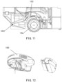
- FIG. 11 shows a schematic view of lifting and lowing control of a cleaning section by a surface cleaning device.
- FIG. 12 shows a disassembled schematic of a surface cleaning device 100.
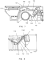
- FIG. 3 shows an internal schematic view of a surface cleaning device according to an embodiment of the present disclosure, wherein a cleaning section is in a lowered state.
- the surface cleaning device may be the surface cleaning device 100 described in FIGS. 1 and 2 .
- FIG. 3 shows a sectional view of the surface cleaning device 100 after being cut along a longitudinal axis and shows related components such as an internal structure of the dirty water tank and a sealing structure of the dirty water tank door. For sake of clarity, only a rear half of the surface cleaning device 100 near its rear side is shown in FIG. 3 . As shown in a disassembled schematic of FIG. 12 , as a non-limiting embodiment, the rear half may be removed from the surface cleaning device as a whole.
- the surface cleaning device 100 may comprise a machine body 101; a cleaning component installed and connected to the machine body 101, the cleaning component may comprise a cleaning section 106 for surface cleaning; a dirty water tank 112 with a dirty water tank inlet 1121; and a dirty water tank inlet sealing component, which is used to seal or open the dirty water tank inlet 1121. More specifically, when the cleaning section 106 is lifted, the dirty water tank inlet 1121 may be sealed, and when the cleaning section 106 is lowered, the dirty water tank inlet 1121 may be opened.
- the cleaning component is a collection of sections in the surface cleaning device used to achieve a surface cleaning function.
- the cleaning component comprises relevant sections for realizing a mopping function, such as a cleaning section and sections for installing and controlling the cleaning section.
- the cleaning component of the surface cleaning device 100 is realized to adopt a roller manner, and accordingly, the cleaning section 106 is a cleaning roller. It may be understood that the present disclosure is also applicable to other types of cleaning components, such as crawler-type cleaning components.
- the cleaning component also comprises a bracket section 103 connected with the cleaning section 106, the bracket section 103 may be lifted and lowered accordingly with lifting and lowering of the cleaning section 106.
- the cleaning section 106 contacts with the ground, wipes and sticks up dirt on the ground through friction between a surface of the cleaning section 106 and the ground, and picks up dirt with rotation of the cleaning section 106 and collects the dirt into the dirty water tank 112.
- the cleaning section 106 may be controlled to be lifted, so that its surface will no longer contact with the ground, which helps to keep the ground dry during sweeping tasks. It may also eliminate unnecessary friction between the cleaning section 106 and the ground and reduce resistance of driving wheels of the surface cleaning device 100 when driving the surface cleaning device 100 to move.
- the cleaning component may comprise a lifting and lowering control section of the cleaning section 106 and the corresponding driving structures for realizing lifting and lowering the cleaning section 106. Methods for lifting and lowering of the cleaning section 106 are not emphasized here, nor do they constitute limitations on the present disclosure.
- FIG. 11 shows an internal schematic view of a surface cleaning device according to an embodiment of the present disclosure.
- the sectional view of FIG. 11 captures another section parallel to the longitudinal axis section of FIG. 3 , which may be located near a left or right side of the surface cleaning device 100 and shows an exemplary lifting and lowering control section of the cleaning section.
- the bracket section 103 may have mounting bracket rails on both the left and right sides for mounting a roller.
- a lifting mechanism of the cleaning section may lift or lower the bracket section 103 under control of a main machine of the surface cleaning device 100, thereby driving the lifting and lowering of the roller.
- FIG. 11 shows an internal schematic view of a surface cleaning device according to an embodiment of the present disclosure.
- the sectional view of FIG. 11 captures another section parallel to the longitudinal axis section of FIG. 3 , which may be located near a left or right side of the surface cleaning device 100 and shows an exemplary lifting and lowering control section of the cleaning section.
- the bracket section 103 may have mounting bracket rails on
- the bracket section 103 may freely rotate around a rotating axis 1031 located near a center of the surface cleaning device 100 under driving of the lifting and lowering structure of the cleaning section, so as to switch between a lifted state and a lowered state with respect to the ground as required.
- the cleaning unit 106 is in a lowered state, and the dirty water tank inlet 1121 of the dirty water tank 112 is in an open state. In this state, the dirty water may enter the dirty water tank 112. More specifically, from a perspective of FIG. 3 , the cleaning section 106 rotates clockwise in working state.
- a water injection port may be provided on the bracket section 103 over the roller. The water injection port may drip clear water into the roller to keep the roller in a wet state. The wet roller sticks up dirt on the ground and then rotates clockwise to pick up the dirt.
- the dirt is scraped off the roller by the scraper strip 108 and enters the dirty water tank 112 together with the dirty water squeezed from the roller. This process may be repeated to realize mopping of the ground and real-time self-cleaning of the roller.
- FIG. 7 shows an internal schematic view of a surface cleaning device according to an embodiment of the present disclosure, wherein the cleaning section is in a lifted state.
- FIG. 7 is a schematic view of a cross-section at a same position as FIG. 3 , wherein the cleaning section 106 is in a lifted state.
- the cleaning section 106 is lifted relative to the ground with the bracket section 103, and the dirty water tank inlet 1121 of the dirty water tank 112 is sealed.
- dirty water in the dirty water tank 112 is sealed therein. Even if the user lifts and turns the surface cleaning device over, dirty water will not leak out of the dirty water tank inlet 1121.
- inlet and closing of the dirty water tank inlet of the surface cleaning device of the present disclosure realizes a linkage with lifting and lowered states of the cleaning section through the dirty water tank inlet sealing component. That is, when the cleaning section 106 is lowered, the dirty water tank inlet 1121 opens, and when the cleaning section 106 is lifted, the dirty water tank inlet 1121 closes. Therefore, this manner may effectively prevent dirty water leakage and improve user experience.
- the surface cleaning device 102 may also be further configured to, in response to detection of being lifted, e.g., being taken off a surface to be cleaned by a user manually, immediately switch the cleaning section to a lifted state, so that even if the user lifts the surface cleaning device while a floor mopping function is in progress, the dirty water tank inlet may be closed in time before the surface cleaning device is turned over.
- the dirty water tank inlet sealing component may further comprise: a convex rib 131 fixed on the bracket section 103; a dirty water tank door movably installed at the dirty water tank inlet 121; and a transmission mechanism connected between the convex rib 131 and a dirty water tank door 111.
- a transmission mechanism is used to transmit different forces applied on the dirty water tank door 111 by lifting or lowering the cleaning component.
- a dirty water tank inlet sealing component may form a linkage mechanism between a bracket section and a dirty water tank door through multiple components.
- a dirty water tank door 111 for sealing the dirty water tank inlet 1121 is provided at the dirty water tank inlet 121 of the dirty water tank 112.
- the dirty water tank door 111 may be arranged to seal the dirty water tank inlet 121 by default and only open when the cleaning component is in a lowered state. Therefore, according to an embodiment of the present disclosure, the dirty water tank door 111 may be rotatably mounted on an internal side of the dirty water tank inlet 1121 through a spring hinge 114, and the spring hinge 114 is arranged to provide a bias force that causes the dirty water tank door 111 to seal the dirty water tank inlet 1121.
- FIG. 4 shows a sectionally enlarged view of a dirty water tank inlet 1121 according to an embodiment of the present disclosure.
- a spring hinge 114 is disposed on the upper section of the inner side of the dirty water tank inlet 1121 (that is, inside the dirty water tank 112), and the upper end of the dirty water tank door 111 may be fixedly connected with the spring hinge 114, so that the dirty water tank door 111 may rotate around a spring axis 1140 of the spring hinge 114.
- the spring body of the spring hinge 114 may be placed in the mounting seat above the dirty water tank 112.
- the spring hinge 114 is arranged to provide the dirty water tank door 111 with a bias force (for example, using a compression spring) to deflect it clockwise under a default state, so that the dirty water tank door 111 may tightly press the dirty water tank inlet 1121 clockwise and upward under a bias force, thereby sealing the dirty water tank inlet 1121.
- a bias force for example, using a compression spring
- FIG. 4 the arrangements of the spring hinge and the dirty water tank door shown in FIG. 4 are only examples. Those skilled in the art may understand that other methods may also be used to achieve a default normally closed effect of the dirty water tank inlet.
- the dirty water tank door 111 may be disposed at an external side of the dirty water tank inlet.
- the spring hinge 114 may be arranged to provide the dirty water tank door 111 with a bias force (such as using a drag spring) to deflect it anticlockwise under a default state, so that the dirty water tank door 111 may press the dirty water tank inlet 1121 anticlockwise and downward under the bias force, and an effect of sealing the dirty water tank inlet 1121 may also be achieved.
- a bias force such as using a drag spring
- a sealing section 113 may be installed on a side facing the dirty water tank inlet 1121 on the dirty water tank door 111.
- the sealing section 113 may be rubber, plastic, silicone, or any other suitable water sealing material.
- the sealing section 113 may have a shape and size similar to the dirty water tank inlet 1121, so that when the dirty water tank door 111 presses the dirty water tank inlet 1121 under the bias force of the spring hinge 114, the sealing section 113 may contact the dirty water tank inlet 1121 to seal the dirty water tank inlet 1121.
- the spring hinge 114 that may produce enough bias force under this structure may be selected to ensure that the dirty water tank inlet 1121 may be completely sealed under cooperation of the bias force and the sealing section 113.
- the dirty water tank door 111 is connected to the bracket section 103 through a transmission mechanism, thereby forming a linkage with the bracket section 103.
- the transmission mechanism may be a rotating swing rod 104 of an L-type.
- FIGS. 5 and 9 are partially enlarged views showing the transmission mechanism in FIGS. 3 and 6 , respectively. Comparing FIGS. 3 and 6 with FIGS. 5 and 9 , it may be seen that a rotating shaft 1040 of the rotating swing rod 104 is fixed on the machine body 101, more specifically, fixed on an inner bulkhead of a cabin containing the cleaning component of the machine body 101, which is roughly located above the dirty water tank inlet 1121.
- the rotation shaft of the rotating swing rod 104 is disposed in a corner, and the first swing arm and the second swing arm are at an acute angle, so that the rotating swing rod 104 may freely rotate a certain angle around the rotating shaft.
- the rotating swing rod 104 may rotate between the first angle and the second angle.
- the rotating swing rod 104 is at a first angle, under which the second swing arm 1042 is against a vertical bulkhead of the machine body 101 at a corner of the rotating shaft 1040.
- the rotating swing rod 104 rotates clockwise from the first angle to a second angle.
- the first swing arm is against a horizontal bulkhead of the machine body 101 at the corner of the rotating shaft 1040.
- Any suitable shapes, installation positions and manners of the transmission mechanism may be arranged according to actual needs, and they all fall within scopes of the concepts and protections sought in the present disclosure if only they may realize purposes of the linkage between opening and closing the dirty water tank inlet and lifting and lowering the cleaning section.
- the transmission mechanism realizes a transfer from the bracket section 103 to the dirty water tank inlet. Therefore, one end of the rotating swing rod 104 is connected to the bracket section 103 and the other end is connected to the dirty water tank door 111.
- the bracket section 103 is provided with a convex rib 131, a first swing arm 1041 of the rotating swing rod 104 contacts with the convex rib 131, and a second swing arm 1042 of the rotating swing rod 104 contacts with the dirty water tank door 111.
- the convex rib 131 may be an end edge integrated with the bracket section 103. Comparing FIG. 3 with FIG.
- the convex rib 131 may be designed to contact up and down with the end of the first swing arm 1041 of the rotating swing rod 104 when the bracket section 103 is in a lifted state (as shown in FIG. 7 ), wherein the convex rib 131 is above an end of the first swing arm 1041.
- the rotating swing rod 104 is at the second angle previously mentioned, and the first swing arm 1041 is against the horizontal bulkhead. Therefore, the convex rib 131 and the first swing arm 1041 may be in natural contact.
- the convex rib 131 may also be designed to stay at a higher position in this state than that shown in FIG. 5 without contacting the first swing arm 1041.
- the bracket section 103 rotates around the rotating axis 1031, and the convex rib 131 moves downward accordingly, thereby contacting the end of the first swing arm 1041 and applying downward pressure. Under this pressure, the rotating swing rod 104 rotates anticlockwise from the second angle to a first angle as shown in FIG. 3 .
- shapes and positions of the convex rib 131 in the above example are not restrictive, but may be customized according to the bracket section, the position of the dirty water tank inlet, the bulkhead structure of the bracket installation compartment, and so on.
- the convex rib 131 may also be omitted.
- one end of the transmission mechanism may be directly fixed to the bracket section 103.
- the dirty water tank door 111 is provided with a convex section 118 on a side facing the dirty water tank inlet 121, and the convex section 118 extends out of the dirty water tank inlet 1121 and contacts with the second swing arm 1042 of the rotating swing rod 104.
- a convex section 118 also referred to as a tongue, may be further disposed on the sealing section 113 of the dirty water tank door 111, and the convex section 118 may extend from the dirty water tank inlet 1121.
- the convex section 118 is arranged to enable the second swing arm 1042 of the rotating swing rod 104 to be connected to the dirty water tank door 111.
- the second swing arm 1042 naturally contacts with or does not contact with the convex section 118, so that a bias force of the spring hinge 114 keeps the dirty water tank door 111 in a sealed state.
- the cleaning section 106 is in a lowered state, as shown in FIG.
- the second swing arm 1042 contacts with the convex section 118 and transfers the pressure generated by the downward movement of the convex rib 131 driven by the bracket section to the convex section 118, so that the convex section 118 presses the dirty water tank door 111, making it rotate clockwise around the spring axis 1140 against the bias force of the spring hinge 114, and releasing the sealing state of the dirty water tank door 111, thereby opening the dirty water tank inlet 1121.
- shapes and positions of the convex section 118 in the above example are not restrictive but may be designed according to shapes and positions of the transmission mechanism.
- one end of the transmission mechanism may be designed to directly push the dirty water tank door 111, and it opens the dirty water tank door 111 toward the internal side of dirty water tank 112 as lowering of the cleaning section, so that the dirty water tank inlet 1121 may be opened.
- FIG. 13 is a partial sectional view of a base station according to an embodiment of the present disclosure.
- the base station may be the base station 200 described in FIG. 1 .
- the base station 200 further comprises: a dirty water bucket 201, in which a first channel 211 for dirty water entering and a second channel 212 for air discharging are provided; a dust collection tank 202, in which a third channel 221 for dust entering and an air outlet 222 of dust collection tank for discharging are provided; and an exhauster 203 for generating negative pressure.
- the first channel 211 of the dirty water bucket 201 interfaces with the dirty water tank outlet 128 of the dirty water tank 112 of the surface cleaning device 100
- the third channel 221 of the dust collection tank 202 interfaces with a dust box 115 of the surface cleaning device
- the second channel 212 of the dirty water bucket 201 and the air outlet 222 of the dust collection tank interface with an air inlet 223 of the exhauster 203.
- the surface cleaning device 100 may return to the base station 200 to perform automatic maintenance tasks, including one or more of charging, dust collection, water injection, dirty suction, self-cleaning or other maintenance tasks.
- the base station 200 may at least perform a task of automatically dirty suction and dust collection from the surface cleaning device, and dirty water suction and dust collection share a same set of an exhauster 203.
- FIG. 14 shows a docking view between a surface cleaning device and a base station when performing a dirty suction task.
- the other end of the water suction channel 214 is a water suction port 228 as shown in FIG. 1 .
- the water suction port 228 may interface with the dirty water tank outlet 128 of the dirty water tank 112 of the surface cleaning device 100 after returning to the base station 200.
- a negative pressure generated by the exhauster 203 is used to form a water suction channel from the dirty water tank 112 of the surface cleaning device 100, the water suction channel 214, the first channel 211, the second channel 212, the air inlet 223, and finally to the exhauster 203.
- a water-air separation structure may be further provided in the dirty water bucket 201 to separate water from air sucked into the dirty water bucket 201 under the action of the exhauster 203, so that the separated water remains in the dirty water bucket 201, and the separated air enters the exhauster 203 through the second channel 212.
- the water-air separation structure can effectively avoid sucking dirty water into the exhauster 203 and causing problems such as failure of the exhauster and high noise.
- the water-air separation structure may be arranged as follows. As shown in FIG. 13 , a water outlet of the first channel 211 and an air inlet of the second channel 212 are both disposed above a maximum water storage height of the dirty water bucket 201, and a height of the water outlet of the first channel 211 is lower than a height of the air inlet of the second channel 212. A shield component 231 is disposed between the water outlet of the first channel 211 and the air inlet of the second channel 212.
- FIG. 15 is a top perspective view of a dirty water bucket 201 according to an embodiment of the present disclosure. As shown in FIG.
- the shield component 231 is formed on the upper cover of the dirty water bucket 201 and extends downwardly to shield the water outlet of the first channel 211 from the air inlet of the second channel 212. It may be understood that the shield component 231 is disposed on the upper cover, which may reduce blocks inside the dirty water bucket 201 after opening the upper cover, so as to clean the inside of the dirty water bucket 201.
- dirty water enters the dirty water bucket 201 from the first channel 211, and the dirty water falls due to the block by the shield component 231 and enters a bottom of the dirty water bucket 201, while the air enters the air inlet of the second channel 212, and then enters the air inlet 223 of the exhauster.
- This structure is easy to manufacture and does not increase the manufacturing cost of the dirty collection device 201. It makes use of gravity to naturally achieve the effect of dirty water and air separation by disposing the shield component 231.
- the base station 200 makes use of suction of the exhauster 203 to suck the dust and air in the dust box 115 of the surface cleaning device 100 into the dust collection tank 202.
- the base station 200 may interface with the dust box 115 of the surface cleaning device 100 through the third channel 221.
- a dust bag 204 may be disposed in the dust collection tank 202. Inhaled dust and air enter the dust bag 204, and then are filtered by the dust bag 204. The dust is stored in the dust bag 204, and the air enters the air inlet 223 through the air outlet 222 of the dust collection tank 202, and then enters the exhauster 203.
- dust collection and dirty water suction in the present disclosure share an exhauster.
- the vacuum pump may be omitted, thereby reducing costs and volumes of base stations.
- a cross-sectional area of the first channel 211 is smaller than that of the third channel 221.
- the base station 200 of the present disclosure may obtain a larger air volume when performing dust collection tasks by making the air inlet of the dust collection tank (i.e. the third channel 221) have a larger cross-sectional area than the dirty water inlet of the dirty water bucket 201 (i.e. the first channel 211).
- the cleaning system may further comprise a water suction channel switch component for opening or closing the water suction channel composed of the first channel 211, the second channel 212 and the dirty water tank 112 of the surface cleaning device 100.
- the base station 200 of the present disclosure may perform tasks of dust collection and dirty suction simultaneously. Especially through different designs of cross-sectional areas of the air inlet, a dust collection task side may obtain greater air volume compared with a dirty water suction task side.
- the water suction channel may be closed so that the dust collection task may obtain a full load air volume of the exhauster 203, and closing the water suction channel may significantly improve vacuum degrees during dust collection tasks.
- the water suction channel switch component may be a sealing cover 240 disposed at the first channel 211 or the second channel 212. As shown in FIG. 16 , the sealing cover 240 may be disposed at an end of the first channel 211. When the sealing cover 240 is closed, the water suction channel is closed. It may be understood that the sealing cover 240 may be disposed at other positions, such as the upper end of the first channel 211, the upper end or other positions of the second channel 212. As long as either the first channel 211 or the second channel 212 may be sealed, the water suction channel may be sealed, and vacuum degrees and air volumes of dust collection tasks may be improved. In addition, the water suction channel switch component may also be other forms of components, such as switching valves.
- the water suction channel switch component is a dirty water tank inlet sealing component of the surface cleaning device 100.
- the dirty water tank inlet 1121 may be switched between a sealed state and an open state through the dirty water tank inlet sealing component.
- the dirty water tank door 111 has a similar effect to that of the sealing cover 240.
- the air duct is closed, a vacuum degree may not be formed inside the dirty water tank 112, and the water suction channel is equivalent to being closed, which may significantly improve vacuum degrees during dust collection tasks.
- the cleaning section 106 when the base station 200 is performing a dust collection process of collecting dust from the dust box 115 of the surface cleaning device 100, the cleaning section 106 is placed in a lifted state, and when the base station 200 is performing the dirty water suction or self-cleaning process of collecting dirty from the dirty water tank 112 of the surface cleaning device 100, the cleaning section 106 is placed in a lowered state.
- the dirty water tank inlet sealing component may realize a linkage between opening and closing of the dirty water tank inlet and lifting and lowered states of the cleaning section.
- the dirty water tank inlet 1121 may be opened, so that under an action of the exhauster 203, the dirty water in the dirty water tank 112 is first sucked into the dirty water bucket 201, and then the water used for self-cleaning of the roller, after completing the washing of the roller and the roller cavity, is also sucked into the dirty water bucket 201 through the dirty water tank 112 under the action of suction.
- the dirty water tank inlet 1121 may be closed.
- the water suction channel may be closed when performing dust collection tasks requiring large air volumes and high vacuum degrees by controlling lifting and lowering of the cleaning section. In this manner, there is no need to provide additional components to realize switching of the water suction channel, which further saves cost of the cleaning system.
- the dirty water bucket 201 and dust collection tank 202 of the base station 200 are disposed above the exhauster 203. As shown in FIG. 13 , the dirty water bucket 201 and the dust collection tank 202 are both disposed over the exhauster 203. This arrangement facilitates shortening the air duct and making an overall size of the base station 200 more compact. Also, the exhauster 203 is located below the dirty water bucket 201, which also allows the dirty water bucket 201 to achieve water and air separation in a simple way. On the contrary, if the exhauster 203 is located above the dirty water bucket 201, water may be sucked into the exhauster 203 together with air.
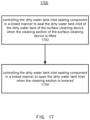
- FIG. 17 shows an example flow chart of a control method 1700 of a surface cleaning device according to an embodiment of the present disclosure.
- the method 1700 may be implemented for example by the surface cleaning device 100 described in the embodiments of the present disclosure.
- method 1700 may comprise: at a step 1702, controlling the dirty water tank inlet sealing component in a linked manner to seal the dirty water tank inlet of the dirty water tank of the surface cleaning device when the cleaning section of the surface cleaning device is lifted.
- a step 1704 controlling the dirty water tank inlet sealing component in a linked manner to open the dirty water tank inlet when the cleaning section is lowered.
- the cleaning section 106 of the surface cleaning device 100 may be lifted or lowered with respect to the ground by controlling the bracket section 103. Accordingly, through the dirty water tank inlet sealing component linked with the bracket section 103, when the cleaning section 106 is lifted, the dirty water tank inlet sealing component (for example, it is composed of the convex ribs 131, a transmission mechanism (such as a rotating swing rod 104), and a dirty water tank door 111) may be controlled in a linked manner to seal the dirty water tank inlet 1121, thereby preventing dirty water leakage from the dirty water tank 112.
- the dirty water tank inlet sealing component for example, it is composed of the convex ribs 131, a transmission mechanism (such as a rotating swing rod 104), and a dirty water tank door 111
- the seal component of the dirty water tank inlet may be controlled in a linked manner to open the dirty water tank inlet 1121. It may be understood that the steps 1702 and 1704 correspond to two different states of controlling the dirty water tank inlet in linked manners, and therefore the steps 1702 and 1704 are not necessarily sequential in execution but may be switched between the two steps according to different working states of the surface cleaning device.
Landscapes
- Cleaning By Liquid Or Steam (AREA)
- Cleaning In General (AREA)
Abstract
The present disclosure provides a surface cleaning device and a cleaning system. The surface cleaning device (100) includes: machine body (101); a cleaning component, installed connected to the machine body (101), the cleaning component comprises a cleaning section (106) for cleaning a surface; a dirty water tank (112) with a dirty water tank inlet (1121); and a dirty water tank inlet sealing component for sealing or opening the dirty water tank inlet (1121), and the dirty water tank inlet sealing component seals the dirty water tank inlet (1121) when the cleaning section (106) is lifted, and opens the dirty water tank inlet (1121) when the cleaning section (106) is lowered. The cleaning system includes a surface cleaning device (100) and a base station (200), and wherein the base station (200) uses a common exhauster (203) to perform automatic dust collection and dirty water suction tasks for the surface cleaning device (100).
Description
- The present disclosure relates to a field of cleaning devices, more specifically, to a surface cleaning device and a cleaning system.
- As a kind of intelligent appliances, cleaning systems such as cleaning robots may automatically clean ground without human operations, providing convenience for modem life. With developments of technology, cleaning robots may realize various cleaning functions, such as sweeping and mopping, which may be further divided into dry mopping and wet mopping. Corresponding to these functions, cleaning robots may also be realized as sweeping robots, mopping robots, sweeping and mopping all-in-one robots, etc. To achieve different functions, different components need to be equipped in cleaning devices. For example, for sweeping, a cleaning equipment needs to be equipped with a dust box to collect dust; for mopping, a cleaning equipment usually needs to be equipped with a clear water tank and a mop; for mop self-cleaning, a cleaning equipment needs to be further equipped with a dirty water tank to collect dirty water generated during a cleaning process.
- In one aspect, these components need to be cleaned and maintained regularly, which increases burden of users. In another aspect, an increase of components causes additional problems. For example, for a cleaning robot equipped with a dirty water tank, it is difficult to seal the dirty water tank because it needs to be opened for recycling dirty water when mopping the floor. However, users may sometimes lift a robot and turn the robot over to check or clean a side brush, a dust suction port, a roller brush, and other components used for sweeping the floor. It is easy to cause dirty water leakage if a dirty water tank is not sealed, and user experience is poor.
- To reduce burdens of users, some cleaning systems equip robots with compatible base stations, and robots may return to base stations for maintenance after work. For example,
CN217244111U discloses a maintenance station for a cleaning device. The maintenance station may use an exhauster to suck cleaned dirty water from the cleaning device into a dirty water bucket disposed on a base of the maintenance station. However, in this scheme, the maintenance station only has a function of sucking dirty water, without a function of automatic dust collection. For automatic dust collection, an additional set of an exhauster and an air duct is usually equipped in prior art to collect dust from a dust box of the cleaning device to the base station. In other words, two sets of suction systems are required in base stations, one for dust collection and the other for dirty water suction, resulting in large volume and high cost of base stations. -
CN212118059U discloses a sealing structure for a dirty water box, in which a dirty water inlet is opened when a dirty water box is put into a groove, and the dirty water inlet is sealed when the dirty water box is moved out of the groove. This structure may solve the problem of dirty water leakage when a user takes out the dirty water box to a certain extent, but when the user turns a robot without taking out the dirty water box, the dirty water inlet is open, and dirty water leakage will still occur. - The present disclosure is provided to introduce some concepts that will be further described in the following specific embodiments in a simplified form. The present disclosure is not intended to identify key features or essential features of subject matters required to be protected, nor is it intended to help determine scopes of the subject matters required to be protected.
- One of objects of the present disclosure is to provide a surface cleaning device and a cleaning system. In the surface cleaning device, a sealing structure is disposed at an inlet of a dirty water tank. The sealing structure is linked with lifting and lowering of a cleaning component of the surface cleaning device. Therefore, the inlet of the dirty water tank is opened only when a cleaning component is in a lowered state when performing ground work, while at any other time, the cleaning component is in a lifted state, and the inlet of the dirty water tank is thus sealed to effectively prevent dirty water leakage. In a base station of the cleaning system, a single exhauster system is used for automatic dust collection and dirty extraction, which reduces volumes and costs of the base station. Meanwhile, a linkage sealing structure of the dirty water tank may switch states in a dust collection process and a dirty water extraction process accordingly to improve suction efficiencies of the exhauster.
- According to one aspect of the present disclosure, a surface cleaning device is provided, which comprises: a machine body; a cleaning component, installed and connected to the machine body, the cleaning component comprising a cleaning section for cleaning the surface; a dirty water tank with a dirty water tank inlet; and a dirty water tank inlet sealing component for sealing or opening the dirty water tank inlet, which seals the dirty water tank inlet when the cleaning section is lifted, and opens the dirty water tank inlet when the cleaning section is lowered. In this manner, the dirty water tank inlet may only be opened when the surface cleaning device is performing mopping tasks. Otherwise, the dirty water tank inlet may remain sealed. Users rarely lift and turn a surface cleaning device over when the surface cleaning device is performing mopping tasks. Therefore, the present disclosure may effectively prevent water leakage from dirty water tanks and improve user experiences.
- According to a further embodiment of the present disclosure, the cleaning section is a cleaning roller, and the cleaning component further comprises a bracket section connected with the cleaning section, and the bracket section is lifted and lowered with lifting and lowering of the cleaning section. In this manner, the cleaning section may be lifted and lowered by lifting and lowering the bracket section.
- According to a further embodiment of the present disclosure, the dirty water tank inlet sealing component comprises: a convex rib, fixed on a bracket section; a dirty water tank door which is movably installed at the dirty water tank inlet; and a transmission mechanism, connected between the convex rib and the dirty water tank door for transmitting different forces applied on the dirty water tank door by lifting or lowering the section. In this manner, a linkage between inlet and closing of the dirty water tank inlet and lifting and lowering of the cleaning section is realized.
- According to a further embodiment of the present disclosure, the transmission mechanism is an L-type rotating swing rod, a rotating shaft of the rotating swing rod is fixed on the machine body, wherein a first swing arm of the rotating swing rod contacts the convex rib, and a second swing arm of the rotating swing rod contacts with the dirty water tank door. A transfer between the bracket section and the dirty water tank door may be realized by rotating by disposing the L-type rotating swing rod. This structure is simple and suitable for a compact space in a cleaning component cabin.
- According to a further embodiment of the present disclosure, the dirty water tank door is installed with a sealing section on a side facing the dirty water tank inlet. The leakproofness of the dirty water tank door may be improved by the sealing section.
- According to a further embodiment of the present disclosure, the dirty water tank door is provided with a convex section on a side facing the dirty water tank inlet, which extends from the dirty water tank inlet and contacts a second swing arm of the rotating swing rod. Through the convex section, the transmission may be further extended to the dirty water tank door in case the rotating swing rod may not reach the dirty water tank door, and a structure of the rotating swing rod may also be kept simple.
- According to a further embodiment of the present disclosure, the dirty water tank door is rotatably mounted on an internal side of the dirty water tank inlet through a spring hinge, and the spring hinge is arranged to provide a bias force that causes the dirty water tank door to seal the dirty water tank inlet. The dirty water tank inlet may be kept normally closed by the spring hinge.
- According to another aspect of the present disclosure, a cleaning system is provided, the cleaning system has a base station and the surface cleaning device as described in the embodiments of the present disclosure, wherein the surface cleaning device further comprises a dust box; and the base station further comprises: a dirty water bucket, in which a first channel for dirty water entering and a second channel for air discharging are disposed; a dust collection tank, in which a third channel for dust entering and an air outlet for air discharging are disposed; and an exhauster for generating negative pressure, wherein the first channel of the dirty water bucket interfaces with the water outlet of the dirty water tank of the surface cleaning device, the third channel of the dust collection tank interfaces with a dust box of the surface cleaning device, and the second channel of the dirty water bucket and the air outlet of the dust collection tank interface with an air inlet of the exhauster. In this manner, a conventional vacuum pump for dirty water suction is saved, cost of the base station is reduced, and volumes of the base station become more compact by disposing a common exhauster.
- According to a further embodiment of the present disclosure, a cross-sectional area of the first channel is smaller than a cross-sectional area of the third channel. In this manner, a dust collection side may obtain a required greater vacuum degree and air volume.
- According to a further embodiment of the present disclosure, the cleaning system further comprises a water suction channel switch component, which is used to open or seal a water suction channel comprising the first channel, the second channel, and the dirty water tank of the surface cleaning device. The water suction channel may be closed by the water suction channel switch component, thereby significantly improving a vacuum degree and air volume during dust collection.
- According to a further embodiment of the present disclosure, the water suction channel switch component is a sealing cover disposed in the first channel or the second channel. The water suction channel may be sealed in a simple structure by disposing the sealing cover.
- According to a further embodiment of the present disclosure, the water suction channel switch component is the dirty water tank inlet sealing component of the surface cleaning device of the present disclosure. In this manner, opening and closing of the water suction channel may be performed without additional components, further simplifying a structure of the surface cleaning device and reducing its cost.
- According to a further embodiment of the present disclosure, the cleaning section is placed in a lifted state when the base station performs a dust collection process of collecting dust from the dust box of the surface cleaning device, and the cleaning section is placed in a lowered state when the base station performs a dirty water suction or self-cleaning process of collecting dirty from the dirty water tank of the surface cleaning device. In this manner, the water suction channel may be opened and closed by controlling states of the cleaning section, and control logics may be effectively combined with maintenance tasks performed by the base station.
- According to a further embodiment of the present disclosure, the dirty water bucket of the base station is provided with a water-air separation structure, which is used to separate water from air sucked into the dirty water bucket under the action of the exhauster, so that the separated water remains in the dirty water bucket, and the separated air enters the exhauster through the second channel. This water-air separation structure utilizes a principle of gravity and has a simple structure. Also, it ensures that water will not enter the exhauster and cause exhauster failure or noise problems.
- According to another aspect of the present disclosure, a control method for the surface cleaning device in the present disclosure is provided. The method comprises: controlling the dirty water tank inlet sealing component in a linked manner to seal the dirty water tank inlet of the dirty water tank of the surface cleaning device when the cleaning section of the surface cleaning device is lifted; and controlling the dirty water tank inlet sealing component in a linked manner to open the dirty water tank inlet when the cleaning section is lowered. In this manner, a linkage control between lifting and lowering of the cleaning section of the surface cleaning device and inlet and closing of the dirty water tank inlet may be realized, so as to ensure that the dirty water tank inlet may be sealed without leakage when the surface cleaning device is lifted or turned over, thereby improving user experiences.
- These and other features and advantages will become apparent by reading the following detailed description and referring to the associated drawings. It should be understood that the above general description and the following detailed description are only illustrative and do not limit aspects of required protections.
- In order to understand in detail the methods used for the above features of the present disclosure, the contents briefly outlined above can be described in more detail with reference to various embodiments, some of which are shown in attached drawings. However, it should be noted that the attached drawings only show some typical aspects of the present disclosure, so they should not be considered as limiting their scope, because the description may allow other equally effective aspects.
-
FIG. 1 shows a schematic view of a cleaning system according to an embodiment of the present disclosure. -
FIG. 2 shows a rear view of a surface cleaning device inFIG. 1 . -
FIG. 3 shows an internal schematic view of a surface cleaning device according to an embodiment of the present disclosure. -
FIG. 4 shows a partially enlarged view of a dirty water tank inlet according to an embodiment of the present disclosure. -
FIG. 5 shows a partially enlarged view of a transmission mechanism section inFIG. 3 . -
FIG. 6 shows an external perspective view of a dirty water tank according to an embodiment of the present disclosure. -
FIG. 7 shows an internal schematic view of a surface cleaning device according to an embodiment of the present disclosure. -
FIG. 8 shows a partially enlarged view of a dirty water tank inlet according to an embodiment of the present disclosure. -
FIG. 9 shows a partially enlarged view of a transmission mechanism section inFIG. 7 . -
FIG. 10 shows an external perspective view of a dirty water tank according to an embodiment of the present disclosure. -
FIG. 11 shows a schematic view of lifting and lowering control of a cleaning section according to an embodiment of the present disclosure. -
FIG. 12 shows a disassembled schematic of a surface cleaning device according to an embodiment of the present disclosure. -
FIG. 13 shows a partial sectional view of a base station according to an embodiment of the present disclosure. -
FIG. 14 shows a docking view of a surface cleaning device and a base station when performing dirty suction task according to an embodiment of the present disclosure. -
FIG. 15 is a top perspective view of a dirty water bucket according to an embodiment of the present disclosure. -
FIG. 16 shows a partial sectional view of a base station according to an embodiment of the present disclosure. -
FIG. 17 shows an example flow chart of a control method of a surface cleaning device according to an embodiment of the present disclosure. - 100 surface cleaning device; 127 dust collection air suction port; 128 dirty water tank outlet; 129 dust collection air blowing port; 130 clear water tank water injection port; 101 machine body; 103 bracket section; 1031 rotating axis; 104 rotating swing rod; 1040 rotating shaft; 1041 first swing arm; 1042 second swing arm; 106 cleaning section; 108 scraper strip; 111 dirty water tank door; 112 dirty water tank; 1121 dirty water tank inlet; 113 sealing section; 114 spring hinge; 1140 spring axis; 115 dust box; 118 convex section; 131 convex rib; 200 base station; 201 dirty water bucket; 202 dust collection tank; 203 exhauster; 204 dust bag; 211 first channel; 212 second channel; 221 third channel; 222 air outlet; 223 air inlet; 227 base station dust collection air suction port; 228 water suction port; 229 base station dust collection air blowing port; 230 water injection port; 231 shield component.
- The embodiments of the present disclosure will be described in more detail below with reference to the attached drawings. Although some embodiments of the present disclosure are shown in the attached drawings, it should be understood that the present disclosure can be realized in various forms and should not be interpreted as limited to the embodiments described herein. On the contrary, these embodiments are provided for a more thorough and complete understanding of the present disclosure. It should be understood that drawings and embodiments of the present disclosure are only for illustrative purposes and are not intended to limit scopes of protection of the present disclosure.
- In the description of the present disclosure, it should be noted that, unless otherwise specified, term "multiple" means more than two; orientational or positional relationships indicated by terms "upper", "lower", "left", "right", "inner" and "outer" and the like are only for convenience of describing and simplifying the description of the present disclosure, rather than indicating or implying that devices or elements referred to must have a specific orientation, be constructed and operated in a specific orientation, and therefore may not be understood as a limitation of the present disclosure. In addition, terms "first", "second", and "third" are used for descriptive purposes only and may not be understood as indicating or implying relative importance. "Vertical" is not strictly vertical, but within an allowable range of error. "Parallel" is not strictly parallel, but within an allowable range of error.
- Orientation terms appearing in the following description are directions shown in the drawings, and do not limit specific structures of the present disclosure. In the description of the present disclosure, it should also be noted that, unless otherwise specified and defined, terms "mount", "connected", and "connect" should be comprehended in a broad sense. For example, the terms may be a fixed connection, or a detachable connection, or an integrated connection; or may be a direct connection or an indirect connection via an intermediate medium. For those of ordinary skill in the art, specific meanings of foregoing terms in the present disclosure may be understood based on specific situations.
- The reference to "embodiment" herein means that specific features, structures or characteristics described in combination with the embodiments may be included in at least one embodiment of the present disclosure. The phrase appearing in various positions of the specification does not necessarily refer to a same embodiment, nor does it refer to an independent or alternative embodiment mutually exclusive with other embodiments. Those skilled in the art understand explicitly and implicitly that the embodiments described herein may be combined with other embodiments.
- In the description of the embodiment of the present disclosure, the term "and/or" is only an association relationship describing the associated object, indicating that there may be three kinds of relationships, such as A and/or B, which may indicate that there are three cases: A alone, A and B simultaneously, and B alone. In addition, the character "j" herein generally indicates that the previous and latter associated objects is an "or" relationship.
-
FIG. 1 is a schematic view of a cleaning system according to an embodiment of the present disclosure. As shown inFIG. 1 , the cleaning system may comprise asurface cleaning device 100 and abase station 200. Thebase station 200 may be configured to perform automatic maintenance tasks when thesurface cleaning device 100 returns to thebase station 200. The automatic maintenance tasks may comprise one or more of charging, water injection, dust collection, dirt suction and self-cleaning. In order to perform these tasks, thebase station 200 and the corresponding ports of thesurface cleaning device 100 are connected. As a non-limiting example, thesurface cleaning device 100 may be a sweeping and mopping integrated cleaning robot with sweeping and mopping functions. Accordingly, thesurface cleaning device 100 comprises a dust box for collecting dust inhaled from the ground during sweeping, a clear water tank for supplying water to a mopping cleaning component, and a dirty water tank for collecting dirt and dirty water generated by the mopping cleaning component wiping the ground. It should be noted that the description of cleaning robots as an example of surface cleaning device in the drawings of the present disclosure is only for the convenience of description. Those skilled in the art will understand that the structure and improvement points of the present disclosure are not only applicable to cleaning robots, but also applicable to other forms of surface cleaning devices, such as handheld cleaning devices. -
FIG. 2 shows a rear view of asurface cleaning device 100 inFIG. 1 . In drawings of the present disclosure, front and rear sides of the surface cleaning device are distinguished by referring to a forward direction of moving of the surface cleaning device. It may be understood that a rear side of thesurface cleaning device 100 inFIG. 1 interfaces with thebase station 200. As shown inFIG. 2 , corresponding to sweeping and mopping functions of thesurface cleaning device 100, a rear panel of thesurface cleaning device 100 is provided with a clear water tankwater injection port 130, a dirty watertank water outlet 128, and a dust collectionair suction port 127 and a dust collectionair blowing port 129 arranged on both sides of the clear water tankwater injection port 130. It should be understood that an interface layout of the rear panel shown inFIG. 2 is only an example, and different interfaces and layouts may be provided as required. InFIG. 1 , thebase station 200 and the surface cleaning device inFIG. 2 are correspondingly provided with a base station dust collectionair suction port 227, a base station dust collectionair blowing port 229, awater injection port 230 and awater suction port 228. When thesurface cleaning device 100 returns and docks at thebase station 200, corresponding ports of thebase station 200 and thesurface cleaning device 100 may be interfaced respectively. It should be understood that interfaces described inFIGS. 1 and 2 are only examples. Arrangements of these ports depend on functions of thesurface cleaning device 100 and automatic maintenance functions provided by thebase station 200. For example, in case that thebase station 200 does not have a function of automatic water injection to thesurface cleaning device 100, thebase station 200 may not be provided with awater injection port 230, and the clear water tank on thesurface cleaning device 100 may not be provided with a clear water tankwater injection port 130. - Details of various embodiments of the
surface cleaning device 100 of the present disclosure are described below in combination withFIGS. 3 to 12 , wherein inFIGS. 3 to 6 , the cleaning section of thesurface cleaning device 100 is in a lowered state. InFIGS. 7 to 10 , the cleaning section of thesurface cleaning device 100 is in a lifted state.FIG. 11 shows a schematic view of lifting and lowing control of a cleaning section by a surface cleaning device.FIG. 12 shows a disassembled schematic of asurface cleaning device 100. -
FIG. 3 shows an internal schematic view of a surface cleaning device according to an embodiment of the present disclosure, wherein a cleaning section is in a lowered state. The surface cleaning device may be thesurface cleaning device 100 described inFIGS. 1 and 2 .FIG. 3 shows a sectional view of thesurface cleaning device 100 after being cut along a longitudinal axis and shows related components such as an internal structure of the dirty water tank and a sealing structure of the dirty water tank door. For sake of clarity, only a rear half of thesurface cleaning device 100 near its rear side is shown inFIG. 3 . As shown in a disassembled schematic ofFIG. 12 , as a non-limiting embodiment, the rear half may be removed from the surface cleaning device as a whole. - According to an embodiment of the present disclosure, as shown in
FIG. 3 , thesurface cleaning device 100 may comprise amachine body 101; a cleaning component installed and connected to themachine body 101, the cleaning component may comprise acleaning section 106 for surface cleaning; adirty water tank 112 with a dirtywater tank inlet 1121; and a dirty water tank inlet sealing component, which is used to seal or open the dirtywater tank inlet 1121. More specifically, when thecleaning section 106 is lifted, the dirtywater tank inlet 1121 may be sealed, and when thecleaning section 106 is lowered, the dirtywater tank inlet 1121 may be opened. - The cleaning component is a collection of sections in the surface cleaning device used to achieve a surface cleaning function. For example, in an example sweeping and mopping all-in-one cleaning robot, the cleaning component comprises relevant sections for realizing a mopping function, such as a cleaning section and sections for installing and controlling the cleaning section. As a non-limiting example, in various embodiments of the present disclosure, the cleaning component of the
surface cleaning device 100 is realized to adopt a roller manner, and accordingly, thecleaning section 106 is a cleaning roller. It may be understood that the present disclosure is also applicable to other types of cleaning components, such as crawler-type cleaning components. - According to an embodiment of the present disclosure, the cleaning component also comprises a
bracket section 103 connected with thecleaning section 106, thebracket section 103 may be lifted and lowered accordingly with lifting and lowering of thecleaning section 106. When thesurface cleaning device 100 is performing mopping tasks, thecleaning section 106 contacts with the ground, wipes and sticks up dirt on the ground through friction between a surface of thecleaning section 106 and the ground, and picks up dirt with rotation of thecleaning section 106 and collects the dirt into thedirty water tank 112. When thesurface cleaning device 100 is not performing mopping tasks, for example, when thesurface cleaning device 100 is performing sweeping tasks, or when mopping tasks have been completed, or when wet cleaning is required to be avoided in case of carpet cleaning, or when thesurface cleaning device 100 is returning to the base station, thecleaning section 106 may be controlled to be lifted, so that its surface will no longer contact with the ground, which helps to keep the ground dry during sweeping tasks. It may also eliminate unnecessary friction between thecleaning section 106 and the ground and reduce resistance of driving wheels of thesurface cleaning device 100 when driving thesurface cleaning device 100 to move. For this reason, the cleaning component may comprise a lifting and lowering control section of thecleaning section 106 and the corresponding driving structures for realizing lifting and lowering thecleaning section 106. Methods for lifting and lowering of thecleaning section 106 are not emphasized here, nor do they constitute limitations on the present disclosure. -
FIG. 11 shows an internal schematic view of a surface cleaning device according to an embodiment of the present disclosure. The sectional view ofFIG. 11 captures another section parallel to the longitudinal axis section ofFIG. 3 , which may be located near a left or right side of thesurface cleaning device 100 and shows an exemplary lifting and lowering control section of the cleaning section. As an example, thebracket section 103 may have mounting bracket rails on both the left and right sides for mounting a roller. A lifting mechanism of the cleaning section may lift or lower thebracket section 103 under control of a main machine of thesurface cleaning device 100, thereby driving the lifting and lowering of the roller. In one example, as shown inFIG. 5 , thebracket section 103 may freely rotate around a rotatingaxis 1031 located near a center of thesurface cleaning device 100 under driving of the lifting and lowering structure of the cleaning section, so as to switch between a lifted state and a lowered state with respect to the ground as required. - In an example of
FIG. 3 , thecleaning unit 106 is in a lowered state, and the dirtywater tank inlet 1121 of thedirty water tank 112 is in an open state. In this state, the dirty water may enter thedirty water tank 112. More specifically, from a perspective ofFIG. 3 , thecleaning section 106 rotates clockwise in working state. As a non-limiting example, a water injection port may be provided on thebracket section 103 over the roller. The water injection port may drip clear water into the roller to keep the roller in a wet state. The wet roller sticks up dirt on the ground and then rotates clockwise to pick up the dirt. After contact and squeezing by ascraper strip 108 arranged on an external side of thedirty water tank 112, the dirt is scraped off the roller by thescraper strip 108 and enters thedirty water tank 112 together with the dirty water squeezed from the roller. This process may be repeated to realize mopping of the ground and real-time self-cleaning of the roller. - As a comparison,
FIG. 7 shows an internal schematic view of a surface cleaning device according to an embodiment of the present disclosure, wherein the cleaning section is in a lifted state.FIG. 7 is a schematic view of a cross-section at a same position asFIG. 3 , wherein thecleaning section 106 is in a lifted state. As shown inFIG. 7 , in this state, thecleaning section 106 is lifted relative to the ground with thebracket section 103, and the dirtywater tank inlet 1121 of thedirty water tank 112 is sealed. At this time, dirty water in thedirty water tank 112 is sealed therein. Even if the user lifts and turns the surface cleaning device over, dirty water will not leak out of the dirtywater tank inlet 1121. - In the above manner, inlet and closing of the dirty water tank inlet of the surface cleaning device of the present disclosure realizes a linkage with lifting and lowered states of the cleaning section through the dirty water tank inlet sealing component. That is, when the
cleaning section 106 is lowered, the dirtywater tank inlet 1121 opens, and when thecleaning section 106 is lifted, the dirtywater tank inlet 1121 closes. Therefore, this manner may effectively prevent dirty water leakage and improve user experience. Optionally, the surface cleaning device 102 may also be further configured to, in response to detection of being lifted, e.g., being taken off a surface to be cleaned by a user manually, immediately switch the cleaning section to a lifted state, so that even if the user lifts the surface cleaning device while a floor mopping function is in progress, the dirty water tank inlet may be closed in time before the surface cleaning device is turned over. - According to an embodiment of the present disclosure, the dirty water tank inlet sealing component may further comprise: a
convex rib 131 fixed on thebracket section 103; a dirty water tank door movably installed at the dirty water tank inlet 121; and a transmission mechanism connected between theconvex rib 131 and a dirtywater tank door 111. A transmission mechanism is used to transmit different forces applied on the dirtywater tank door 111 by lifting or lowering the cleaning component. In order to realize a linkage between inlet and closing of the dirty water tank inlet and lifting and lowering of the cleaning component, a dirty water tank inlet sealing component may form a linkage mechanism between a bracket section and a dirty water tank door through multiple components. In this example, a dirtywater tank door 111 for sealing the dirtywater tank inlet 1121 is provided at the dirty water tank inlet 121 of thedirty water tank 112. The dirtywater tank door 111 may be arranged to seal the dirty water tank inlet 121 by default and only open when the cleaning component is in a lowered state. Therefore, according to an embodiment of the present disclosure, the dirtywater tank door 111 may be rotatably mounted on an internal side of the dirtywater tank inlet 1121 through aspring hinge 114, and thespring hinge 114 is arranged to provide a bias force that causes the dirtywater tank door 111 to seal the dirtywater tank inlet 1121. -
FIG. 4 shows a sectionally enlarged view of a dirtywater tank inlet 1121 according to an embodiment of the present disclosure. As shown inFIG. 4 , aspring hinge 114 is disposed on the upper section of the inner side of the dirty water tank inlet 1121 (that is, inside the dirty water tank 112), and the upper end of the dirtywater tank door 111 may be fixedly connected with thespring hinge 114, so that the dirtywater tank door 111 may rotate around aspring axis 1140 of thespring hinge 114. The spring body of thespring hinge 114 may be placed in the mounting seat above thedirty water tank 112. Thespring hinge 114 is arranged to provide the dirtywater tank door 111 with a bias force (for example, using a compression spring) to deflect it clockwise under a default state, so that the dirtywater tank door 111 may tightly press the dirtywater tank inlet 1121 clockwise and upward under a bias force, thereby sealing the dirtywater tank inlet 1121. It may be understood that the arrangements of the spring hinge and the dirty water tank door shown inFIG. 4 are only examples. Those skilled in the art may understand that other methods may also be used to achieve a default normally closed effect of the dirty water tank inlet. For example, the dirtywater tank door 111 may be disposed at an external side of the dirty water tank inlet. Accordingly, thespring hinge 114 may be arranged to provide the dirtywater tank door 111 with a bias force (such as using a drag spring) to deflect it anticlockwise under a default state, so that the dirtywater tank door 111 may press the dirtywater tank inlet 1121 anticlockwise and downward under the bias force, and an effect of sealing the dirtywater tank inlet 1121 may also be achieved. - An embodiment of dirty
water tank door 111 installed on an internal side of the dirtywater tank inlet 1121 shown inFIG. 4 is still taken as an example for illustration. As shown inFIG. 4 , asealing section 113 may be installed on a side facing the dirtywater tank inlet 1121 on the dirtywater tank door 111. As a non-limiting example, thesealing section 113 may be rubber, plastic, silicone, or any other suitable water sealing material. Thesealing section 113 may have a shape and size similar to the dirtywater tank inlet 1121, so that when the dirtywater tank door 111 presses the dirtywater tank inlet 1121 under the bias force of thespring hinge 114, thesealing section 113 may contact the dirtywater tank inlet 1121 to seal the dirtywater tank inlet 1121. To achieve good sealing effect, thespring hinge 114 that may produce enough bias force under this structure may be selected to ensure that the dirtywater tank inlet 1121 may be completely sealed under cooperation of the bias force and thesealing section 113. - The dirty
water tank door 111 is connected to thebracket section 103 through a transmission mechanism, thereby forming a linkage with thebracket section 103. According to an embodiment of the present disclosure, the transmission mechanism may be arotating swing rod 104 of an L-type.FIGS. 5 and9 are partially enlarged views showing the transmission mechanism inFIGS. 3 and6 , respectively. ComparingFIGS. 3 and6 withFIGS. 5 and9 , it may be seen that arotating shaft 1040 of therotating swing rod 104 is fixed on themachine body 101, more specifically, fixed on an inner bulkhead of a cabin containing the cleaning component of themachine body 101, which is roughly located above the dirtywater tank inlet 1121. In a specific non-limiting example shown in the above drawings, there is a corner defined by an installation area of different components above the dirtywater tank inlet 1121. Accordingly, the rotation shaft of therotating swing rod 104 is disposed in a corner, and the first swing arm and the second swing arm are at an acute angle, so that therotating swing rod 104 may freely rotate a certain angle around the rotating shaft. As shown inFIGS. 3 ,5 ,6 , and9 , corresponding to the lifting and lowering of the cleaning section, therotating swing rod 104 may rotate between the first angle and the second angle. InFIGS. 3 and5 , corresponding to a lowered state of the cleaning component, therotating swing rod 104 is at a first angle, under which thesecond swing arm 1042 is against a vertical bulkhead of themachine body 101 at a corner of therotating shaft 1040. InFIGS. 6 and9 , corresponding to a lifted state of the cleaning component, therotating swing rod 104 rotates clockwise from the first angle to a second angle. At the second angle, the first swing arm is against a horizontal bulkhead of themachine body 101 at the corner of therotating shaft 1040. It should be understood that therotating swing rod 104 described in the above drawings is only a specific example of the transmission mechanism designed and adopted for a specific internal structure of thesurface cleaning device 100 involved in these drawings. Any suitable shapes, installation positions and manners of the transmission mechanism may be arranged according to actual needs, and they all fall within scopes of the concepts and protections sought in the present disclosure if only they may realize purposes of the linkage between opening and closing the dirty water tank inlet and lifting and lowering the cleaning section. - In the embodiment of the present disclosure, the transmission mechanism realizes a transfer from the
bracket section 103 to the dirty water tank inlet. Therefore, one end of therotating swing rod 104 is connected to thebracket section 103 and the other end is connected to the dirtywater tank door 111. According to an embodiment of the present disclosure, thebracket section 103 is provided with aconvex rib 131, afirst swing arm 1041 of therotating swing rod 104 contacts with theconvex rib 131, and asecond swing arm 1042 of therotating swing rod 104 contacts with the dirtywater tank door 111. According to an example of the present disclosure, theconvex rib 131 may be an end edge integrated with thebracket section 103. ComparingFIG. 3 withFIG. 7 , it may be seen that theconvex rib 131 may be designed to contact up and down with the end of thefirst swing arm 1041 of therotating swing rod 104 when thebracket section 103 is in a lifted state (as shown inFIG. 7 ), wherein theconvex rib 131 is above an end of thefirst swing arm 1041. At that time, therotating swing rod 104 is at the second angle previously mentioned, and thefirst swing arm 1041 is against the horizontal bulkhead. Therefore, theconvex rib 131 and thefirst swing arm 1041 may be in natural contact. Alternatively, theconvex rib 131 may also be designed to stay at a higher position in this state than that shown inFIG. 5 without contacting thefirst swing arm 1041. As thecleaning section 106 is lowered, thebracket section 103 rotates around the rotatingaxis 1031, and theconvex rib 131 moves downward accordingly, thereby contacting the end of thefirst swing arm 1041 and applying downward pressure. Under this pressure, therotating swing rod 104 rotates anticlockwise from the second angle to a first angle as shown inFIG. 3 . It may be understood that shapes and positions of theconvex rib 131 in the above example are not restrictive, but may be customized according to the bracket section, the position of the dirty water tank inlet, the bulkhead structure of the bracket installation compartment, and so on. Any variants fall all within scopes of concepts and protections sought in the present disclosure if only they may realize the purpose of a linkage between opening and closing the dirty water tank inlet and lifting and lowering the cleaning section. In some embodiments, theconvex rib 131 may also be omitted. As an alternative, one end of the transmission mechanism may be directly fixed to thebracket section 103. - According to an embodiment of the present disclosure, the dirty
water tank door 111 is provided with aconvex section 118 on a side facing the dirty water tank inlet 121, and theconvex section 118 extends out of the dirtywater tank inlet 1121 and contacts with thesecond swing arm 1042 of therotating swing rod 104. As shown in sectional views ofFIGS. 4 and8 and outside perspective views of thedirty water tank 112 shown inFIGS. 6 and10 , aconvex section 118, also referred to as a tongue, may be further disposed on thesealing section 113 of the dirtywater tank door 111, and theconvex section 118 may extend from the dirtywater tank inlet 1121. Referring toFIGS. 3 and7 , theconvex section 118 is arranged to enable thesecond swing arm 1042 of therotating swing rod 104 to be connected to the dirtywater tank door 111. For example, as shown inFIG. 3 , when thecleaning section 106 is in a lifted state, thesecond swing arm 1042 naturally contacts with or does not contact with theconvex section 118, so that a bias force of thespring hinge 114 keeps the dirtywater tank door 111 in a sealed state. When thecleaning section 106 is in a lowered state, as shown inFIG. 7 , thesecond swing arm 1042 contacts with theconvex section 118 and transfers the pressure generated by the downward movement of theconvex rib 131 driven by the bracket section to theconvex section 118, so that theconvex section 118 presses the dirtywater tank door 111, making it rotate clockwise around thespring axis 1140 against the bias force of thespring hinge 114, and releasing the sealing state of the dirtywater tank door 111, thereby opening the dirtywater tank inlet 1121. Similarly, shapes and positions of theconvex section 118 in the above example are not restrictive but may be designed according to shapes and positions of the transmission mechanism. Any variants fall within scopes of concepts and protections sought in the present disclosure if only they may realize the purpose of a linkage between opening and closing the dirty water tank inlet and lifting and lowering the cleaning section. For example, as an alternative, one end of the transmission mechanism may be designed to directly push the dirtywater tank door 111, and it opens the dirtywater tank door 111 toward the internal side ofdirty water tank 112 as lowering of the cleaning section, so that the dirtywater tank inlet 1121 may be opened. -
FIG. 13 is a partial sectional view of a base station according to an embodiment of the present disclosure. The base station may be thebase station 200 described inFIG. 1 . As shown inFIG. 13 , thebase station 200 further comprises: adirty water bucket 201, in which afirst channel 211 for dirty water entering and asecond channel 212 for air discharging are provided; adust collection tank 202, in which athird channel 221 for dust entering and anair outlet 222 of dust collection tank for discharging are provided; and anexhauster 203 for generating negative pressure. Wherein, thefirst channel 211 of thedirty water bucket 201 interfaces with the dirtywater tank outlet 128 of thedirty water tank 112 of thesurface cleaning device 100, thethird channel 221 of thedust collection tank 202 interfaces with adust box 115 of the surface cleaning device, and thesecond channel 212 of thedirty water bucket 201 and theair outlet 222 of the dust collection tank interface with anair inlet 223 of theexhauster 203. - As previously described, the
surface cleaning device 100 may return to thebase station 200 to perform automatic maintenance tasks, including one or more of charging, dust collection, water injection, dirty suction, self-cleaning or other maintenance tasks. In an example ofFIG. 13 , thebase station 200 may at least perform a task of automatically dirty suction and dust collection from the surface cleaning device, and dirty water suction and dust collection share a same set of anexhauster 203. - In a dirty suction task, the
base station 200 uses suction of theexhauster 203 to suck dirt together with dirty water in thedirty water tank 112 of thesurface cleaning device 100 into thedirty water bucket 201.FIG. 14 shows a docking view between a surface cleaning device and a base station when performing a dirty suction task. As shown inFIG. 14 , there is an extendedwater suction channel 214 outside thefirst channel 211 of thebase station 200 for dirty water to enter thedirty water bucket 201. The other end of thewater suction channel 214 is awater suction port 228 as shown inFIG. 1 . Thewater suction port 228 may interface with the dirtywater tank outlet 128 of thedirty water tank 112 of thesurface cleaning device 100 after returning to thebase station 200. When theexhauster 203 is started, a negative pressure generated by theexhauster 203 is used to form a water suction channel from thedirty water tank 112 of thesurface cleaning device 100, thewater suction channel 214, thefirst channel 211, thesecond channel 212, theair inlet 223, and finally to theexhauster 203. - In order to prevent dirty water from entering the
exhauster 203, a water-air separation structure may be further provided in thedirty water bucket 201 to separate water from air sucked into thedirty water bucket 201 under the action of theexhauster 203, so that the separated water remains in thedirty water bucket 201, and the separated air enters theexhauster 203 through thesecond channel 212. The water-air separation structure can effectively avoid sucking dirty water into theexhauster 203 and causing problems such as failure of the exhauster and high noise. - As a non-limiting embodiment, the water-air separation structure may be arranged as follows. As shown in
FIG. 13 , a water outlet of thefirst channel 211 and an air inlet of thesecond channel 212 are both disposed above a maximum water storage height of thedirty water bucket 201, and a height of the water outlet of thefirst channel 211 is lower than a height of the air inlet of thesecond channel 212. Ashield component 231 is disposed between the water outlet of thefirst channel 211 and the air inlet of thesecond channel 212.FIG. 15 is a top perspective view of adirty water bucket 201 according to an embodiment of the present disclosure. As shown inFIG. 15 , the upper cover of thedirty water bucket 201 is hidden, and theshield component 231 is formed on the upper cover of thedirty water bucket 201 and extends downwardly to shield the water outlet of thefirst channel 211 from the air inlet of thesecond channel 212. It may be understood that theshield component 231 is disposed on the upper cover, which may reduce blocks inside thedirty water bucket 201 after opening the upper cover, so as to clean the inside of thedirty water bucket 201. When thebase station 200 performs a dirty water suction task, dirty water enters thedirty water bucket 201 from thefirst channel 211, and the dirty water falls due to the block by theshield component 231 and enters a bottom of thedirty water bucket 201, while the air enters the air inlet of thesecond channel 212, and then enters theair inlet 223 of the exhauster. This structure is easy to manufacture and does not increase the manufacturing cost of thedirty collection device 201. It makes use of gravity to naturally achieve the effect of dirty water and air separation by disposing theshield component 231. - In a dust collection task, the
base station 200 makes use of suction of theexhauster 203 to suck the dust and air in thedust box 115 of thesurface cleaning device 100 into thedust collection tank 202. Thebase station 200 may interface with thedust box 115 of thesurface cleaning device 100 through thethird channel 221. Adust bag 204 may be disposed in thedust collection tank 202. Inhaled dust and air enter thedust bag 204, and then are filtered by thedust bag 204. The dust is stored in thedust bag 204, and the air enters theair inlet 223 through theair outlet 222 of thedust collection tank 202, and then enters theexhauster 203. - In this manner, dust collection and dirty water suction in the present disclosure share an exhauster. Compared with traditional automatic dust collection and dirty water suction through an exhauster and a vacuum pump respectively, the vacuum pump may be omitted, thereby reducing costs and volumes of base stations.
- Generally speaking, automatic dust collection requires greater vacuum degree and air volume than dirty suction. Air volume distribution of the exhauster is automatically realized by designing different ratios of dirty water inlet diameter and dust collection inlet diameter. According to an embodiment of the present disclosure, a cross-sectional area of the
first channel 211 is smaller than that of thethird channel 221. Thebase station 200 of the present disclosure may obtain a larger air volume when performing dust collection tasks by making the air inlet of the dust collection tank (i.e. the third channel 221) have a larger cross-sectional area than the dirty water inlet of the dirty water bucket 201 (i.e. the first channel 211). - According to another embodiment of the present disclosure, the cleaning system may further comprise a water suction channel switch component for opening or closing the water suction channel composed of the
first channel 211, thesecond channel 212 and thedirty water tank 112 of thesurface cleaning device 100. Thebase station 200 of the present disclosure may perform tasks of dust collection and dirty suction simultaneously. Especially through different designs of cross-sectional areas of the air inlet, a dust collection task side may obtain greater air volume compared with a dirty water suction task side. Alternatively, the water suction channel may be closed so that the dust collection task may obtain a full load air volume of theexhauster 203, and closing the water suction channel may significantly improve vacuum degrees during dust collection tasks. - According to an embodiment of the present disclosure, the water suction channel switch component may be a sealing
cover 240 disposed at thefirst channel 211 or thesecond channel 212. As shown inFIG. 16 , the sealingcover 240 may be disposed at an end of thefirst channel 211. When the sealingcover 240 is closed, the water suction channel is closed. It may be understood that the sealingcover 240 may be disposed at other positions, such as the upper end of thefirst channel 211, the upper end or other positions of thesecond channel 212. As long as either thefirst channel 211 or thesecond channel 212 may be sealed, the water suction channel may be sealed, and vacuum degrees and air volumes of dust collection tasks may be improved. In addition, the water suction channel switch component may also be other forms of components, such as switching valves. - According to another embodiment of the present disclosure, the water suction channel switch component is a dirty water tank inlet sealing component of the
surface cleaning device 100. As previously described in combination withFIGS. 3-10 , the dirtywater tank inlet 1121 may be switched between a sealed state and an open state through the dirty water tank inlet sealing component. When the dirtywater tank inlet 1121 is closed, no new air or water will enter thedirty water tank 112 from the dirtywater tank inlet 1121. The dirtywater tank door 111 has a similar effect to that of the sealingcover 240. At this time, the air duct is closed, a vacuum degree may not be formed inside thedirty water tank 112, and the water suction channel is equivalent to being closed, which may significantly improve vacuum degrees during dust collection tasks. - According to a further embodiment of the present disclosure, when the
base station 200 is performing a dust collection process of collecting dust from thedust box 115 of thesurface cleaning device 100, thecleaning section 106 is placed in a lifted state, and when thebase station 200 is performing the dirty water suction or self-cleaning process of collecting dirty from thedirty water tank 112 of thesurface cleaning device 100, thecleaning section 106 is placed in a lowered state. As previously described, the dirty water tank inlet sealing component may realize a linkage between opening and closing of the dirty water tank inlet and lifting and lowered states of the cleaning section. When thesurface cleaning device 100 performs dirty suction or self-cleaning processes at thebase station 200, the dirtywater tank inlet 1121 may be opened, so that under an action of theexhauster 203, the dirty water in thedirty water tank 112 is first sucked into thedirty water bucket 201, and then the water used for self-cleaning of the roller, after completing the washing of the roller and the roller cavity, is also sucked into thedirty water bucket 201 through thedirty water tank 112 under the action of suction. In addition, for example, when thebase station 200 is performing dust collection tasks, the dirtywater tank inlet 1121 may be closed. To this end, the water suction channel may be closed when performing dust collection tasks requiring large air volumes and high vacuum degrees by controlling lifting and lowering of the cleaning section. In this manner, there is no need to provide additional components to realize switching of the water suction channel, which further saves cost of the cleaning system. - According to an embodiment of the present disclosure, the
dirty water bucket 201 anddust collection tank 202 of thebase station 200 are disposed above theexhauster 203. As shown inFIG. 13 , thedirty water bucket 201 and thedust collection tank 202 are both disposed over theexhauster 203. This arrangement facilitates shortening the air duct and making an overall size of thebase station 200 more compact. Also, theexhauster 203 is located below thedirty water bucket 201, which also allows thedirty water bucket 201 to achieve water and air separation in a simple way. On the contrary, if theexhauster 203 is located above thedirty water bucket 201, water may be sucked into theexhauster 203 together with air. -
FIG. 17 shows an example flow chart of acontrol method 1700 of a surface cleaning device according to an embodiment of the present disclosure. Themethod 1700 may be implemented for example by thesurface cleaning device 100 described in the embodiments of the present disclosure. As shown inFIG. 17 ,method 1700 may comprise: at astep 1702, controlling the dirty water tank inlet sealing component in a linked manner to seal the dirty water tank inlet of the dirty water tank of the surface cleaning device when the cleaning section of the surface cleaning device is lifted. At astep 1704, controlling the dirty water tank inlet sealing component in a linked manner to open the dirty water tank inlet when the cleaning section is lowered. Taking thesurface cleaning device 100 as an example, as previously described in connection withFIGS. 1-16 , thecleaning section 106 of thesurface cleaning device 100 may be lifted or lowered with respect to the ground by controlling thebracket section 103. Accordingly, through the dirty water tank inlet sealing component linked with thebracket section 103, when thecleaning section 106 is lifted, the dirty water tank inlet sealing component (for example, it is composed of theconvex ribs 131, a transmission mechanism (such as a rotating swing rod 104), and a dirty water tank door 111) may be controlled in a linked manner to seal the dirtywater tank inlet 1121, thereby preventing dirty water leakage from thedirty water tank 112. When thecleaning section 106 is lowered, for performing the floor cleaning task or self-cleaning for example, the seal component of the dirty water tank inlet may be controlled in a linked manner to open the dirtywater tank inlet 1121. It may be understood that thesteps steps - The content already described above includes examples of various aspects of the subject matter required to be protected. Of course, it is impossible to describe every conceivable combination of components or methods for the purpose of describing the required protection subject, but those of ordinary skill in the art should recognize that many further combinations and arrangements of the required protection subject are possible. Thus, the subject matter disclosed is intended to cover all such changes, modifications and changes falling within the spirit and scope of the appended claims.
Claims (15)
- A surface cleaning device (100), comprising:a machine body (101);a cleaning component, installed and connected to the machine body (101), the cleaning component comprising a cleaning section (106) for surface cleaning;a dirty water tank (112) with a dirty water tank inlet (1121); anda dirty water tank inlet sealing component for sealing or opening the dirty water tank inlet (1121), and wherein the dirty water tank inlet sealing component seals the dirty water tank inlet (1121) when the cleaning section (106) is lifted and opens the dirty water tank inlet (1121) when the cleaning section (106) is lowered.
- The surface cleaning device (100) according to Claim 1, wherein the cleaning section (106) is a cleaning roller, and the cleaning component further comprises a bracket section (103) connected with the cleaning section (106), and the bracket section (103) is lifted and lowered with lifting and lowering of the cleaning section (106).
- The surface cleaning device (100) according to Claim 2, wherein the dirty water tank inlet sealing component comprises:a convex rib (131), fixed on a bracket section (103);a dirty water tank door (111), movably installed at the dirty water tank inlet (1121); anda transmission mechanism, connected between the convex rib (131) and the dirty water tank door (111) for transmitting different forces applied on the dirty water tank door (111) by lifting or lowering the cleaning section (106).
- The surface cleaning device (100) according to Claim 3, wherein the transmission mechanism is an L-type rotating swing rod (104), a rotating shaft (1040) of the rotating swing rod (104) is fixed on the machine body (101), a first swing arm (1041) of the rotating swing rod (104) contacts the convex rib (131), and a second swing arm (1042) of the rotating swing rod (104) contacts the dirty water tank door (111).
- The surface cleaning device (100) according to Claim 3, wherein the dirty water tank door (111) is installed with a sealing section (113) on a side facing the dirty water tank inlet (1121).
- The surface cleaning device (100) according to Claim 3, wherein the dirty water tank door (111) is installed with a convex section (118) on a side facing the dirty water tank inlet (121), and the convex section (118) extends from the dirty water tank inlet (121) and contacts a second swing arm (1042) of the rotating swing rod (104).
- The surface cleaning device (100) according to Claim 3, wherein the dirty water tank door (111) is rotatably mounted on an internal side of the dirty water tank inlet (121) through a spring hinge (114), and the spring hinge (114) is arranged to provide a bias force that causes the dirty water tank door (111) to seal the dirty water tank inlet (1121).
- A cleaning system having a base station (200) and a surface cleaning device (100) as claimed in any one of Claims 1-7, wherein the surface cleaning device (100) further comprises a dust box (115); and
the base station (200) further comprises:a dirty water bucket (201), in which a first channel (211) for dirty water entering and a second channel (212) for air discharging are disposed;a dust collection tank (202), in which a third channel for dust entering and an air outlet (222) for air discharging are disposed; andan exhauster for generating negative pressure,wherein the first channel (211) of the dirty water bucket (201) interfaces with a water outlet (128) of a dirty water tank (112) of the surface cleaning device (100), the third channel (221) of the dust collection tank (202) interfaces with a dust box of the surface cleaning device, and the second channel (212) of the dirty water bucket (202) and an air outlet of the dust collection tank (202) interface with an air inlet (223) of the exhauster (203). - The cleaning system according to Claim 8, wherein a cross-sectional area of the first channel (211) is smaller than a cross-sectional area of the third channel (221).
- The cleaning system according to Claims 8 or 9, further comprises a water suction channel switch component, which is used to open or seal a water suction channel comprising the first channel (211), the second channel (212), and the dirty water tank (112) of the surface cleaning device (100).
- The cleaning system according to Claim 10, wherein the water suction channel switch component is a sealing cover (240) disposed at the first channel (211) or the second channel (212).
- The cleaning system according to Claim 10, wherein the water suction channel switch component is the dirty water tank inlet sealing component of the surface cleaning device (100).
- The cleaning system according to Claim 12, wherein the cleaning section (106) is placed in a lifted state when the base station (200) performs a dust collection process of collecting dust from the dust box (115) of the surface cleaning device (100), and the cleaning section (106) is placed in a lowered state when the base station (200) performs a dirty water sucking or self-cleaning process of collecting dirt from the dirty water tank (112) of the surface cleaning device (100).
- The cleaning system according to Claim 8, wherein the dirty water bucket (201) of the base station is provided with a water-air separation structure, which is used to separate water from air sucked into the dirty water bucket (201) under action of the exhauster (203), so that separated water remains in the dirty water bucket (201), and separated air enters the exhauster (203) through the second channel (212).
- A control method for the surface cleaning device as described in any one of Claims 1-7, wherein the method comprises:controlling the dirty water tank inlet sealing component in a linked manner to seal the dirty water tank inlet of the dirty water tank of the surface cleaning device when the cleaning section of the surface cleaning device is lifted; andcontrolling the dirty water tank inlet sealing component in a linked manner to open the dirty water tank inlet when the cleaning section is lowered.
Priority Applications (5)
| Application Number | Priority Date | Filing Date | Title |
|---|---|---|---|
| AU2023375283A AU2023375283B2 (en) | 2023-02-07 | 2023-12-05 | Surface cleaning device and cleaning system |
| US19/150,494 US20260114692A1 (en) | 2023-02-07 | 2023-12-05 | Surface cleaning device and cleaning system |
| KR1020247026016A KR20250144880A (en) | 2023-02-07 | 2023-12-05 | Surface cleaning devices and cleaning systems |
| PCT/EP2023/084378 WO2024165210A1 (en) | 2023-02-07 | 2023-12-05 | Surface cleaning device and cleaning system |
| EP23818048.3A EP4432891A1 (en) | 2023-02-07 | 2023-12-05 | Surface cleaning device and cleaning system |
Applications Claiming Priority (1)
| Application Number | Priority Date | Filing Date | Title |
|---|---|---|---|
| CN202310129530.5A CN118490113A (en) | 2023-02-07 | 2023-02-07 | Surface cleaning device and cleaning system |
Publications (1)
| Publication Number | Publication Date |
|---|---|
| EP4413909A1 true EP4413909A1 (en) | 2024-08-14 |
Family
ID=85704687
Family Applications (1)
| Application Number | Title | Priority Date | Filing Date |
|---|---|---|---|
| EP23162653.2A Withdrawn EP4413909A1 (en) | 2023-02-07 | 2023-03-17 | Surface cleaning device and cleaning system |
Country Status (2)
| Country | Link |
|---|---|
| EP (1) | EP4413909A1 (en) |
| CN (1) | CN118490113A (en) |
Cited By (2)
| Publication number | Priority date | Publication date | Assignee | Title |
|---|---|---|---|---|
| CN121101417A (en) * | 2025-11-11 | 2025-12-12 | 海尔机器人科技(青岛)有限公司 | Wastewater tanks and floor scrubbers |
| DE102024125499A1 (en) * | 2024-09-05 | 2026-03-05 | Alfred Kärcher SE & Co. KG | Dirt fluid tank for a floor cleaning machine, floor cleaning machine and cleaning station |
Citations (6)
| Publication number | Priority date | Publication date | Assignee | Title |
|---|---|---|---|---|
| US2558864A (en) * | 1942-03-25 | 1951-07-03 | Raymond Torin | Vacuum cleaner with selective nozzles and brushes |
| US3197798A (en) * | 1963-01-28 | 1965-08-03 | Tennant Co G H | Scrubbing machine |
| US20060236494A1 (en) * | 2005-04-07 | 2006-10-26 | Tennant Company | Hard and soft floor surface cleaner |
| IT201900001375A1 (en) * | 2019-01-30 | 2020-07-30 | Ip Cleaning S R L | SURFACE CLEANING DEVICE |
| CN212118059U (en) | 2019-12-20 | 2020-12-11 | 深圳市银星智能科技股份有限公司 | Cleaning device |
| CN217244111U (en) | 2022-01-26 | 2022-08-23 | 小窝智能(北京)科技有限公司 | Cleaning device's maintenance station |
-
2023
- 2023-02-07 CN CN202310129530.5A patent/CN118490113A/en active Pending
- 2023-03-17 EP EP23162653.2A patent/EP4413909A1/en not_active Withdrawn
Patent Citations (6)
| Publication number | Priority date | Publication date | Assignee | Title |
|---|---|---|---|---|
| US2558864A (en) * | 1942-03-25 | 1951-07-03 | Raymond Torin | Vacuum cleaner with selective nozzles and brushes |
| US3197798A (en) * | 1963-01-28 | 1965-08-03 | Tennant Co G H | Scrubbing machine |
| US20060236494A1 (en) * | 2005-04-07 | 2006-10-26 | Tennant Company | Hard and soft floor surface cleaner |
| IT201900001375A1 (en) * | 2019-01-30 | 2020-07-30 | Ip Cleaning S R L | SURFACE CLEANING DEVICE |
| CN212118059U (en) | 2019-12-20 | 2020-12-11 | 深圳市银星智能科技股份有限公司 | Cleaning device |
| CN217244111U (en) | 2022-01-26 | 2022-08-23 | 小窝智能(北京)科技有限公司 | Cleaning device's maintenance station |
Cited By (3)
| Publication number | Priority date | Publication date | Assignee | Title |
|---|---|---|---|---|
| DE102024125499A1 (en) * | 2024-09-05 | 2026-03-05 | Alfred Kärcher SE & Co. KG | Dirt fluid tank for a floor cleaning machine, floor cleaning machine and cleaning station |
| WO2026052362A1 (en) | 2024-09-05 | 2026-03-12 | Alfred Kärcher SE & Co. KG | Dirty fluid tank for a floor cleaning machine, floor cleaning machine, and cleaning station |
| CN121101417A (en) * | 2025-11-11 | 2025-12-12 | 海尔机器人科技(青岛)有限公司 | Wastewater tanks and floor scrubbers |
Also Published As
| Publication number | Publication date |
|---|---|
| CN118490113A (en) | 2024-08-16 |
Similar Documents
| Publication | Publication Date | Title |
|---|---|---|
| KR102772524B1 (en) | Robot maintenance station and robot cleaning system | |
| EP1961358B1 (en) | Robot cleaner system having robot cleaner and docking station | |
| KR101202916B1 (en) | Dirt removal system of the robot cleaner | |
| CN111743459A (en) | Smart Cleaning Systems, Autonomous Robots and Base Stations | |
| CN215899556U (en) | Slop pail, separation structure, ground washing assembly and ground washing machine | |
| CN219206787U (en) | Surface cleaning device and cleaning system | |
| EP4613168A1 (en) | Cleaning main unit, dust collection base station, and cleaning system | |
| CN209899274U (en) | Smart Cleaning Systems, Autonomous Robots and Base Stations | |
| CN118490113A (en) | Surface cleaning device and cleaning system | |
| TW202119994A (en) | Base station for stationary emptying of a dirt space of a mobile cleaning apparatus, cleaning system and method | |
| AU2022428023B2 (en) | Self-cleaning dust collection seats and dust collection system | |
| CN110101336A (en) | Wet-dry scrubbing brush for vacuum cleaner | |
| CN112515532A (en) | Dust box assembly, cleaning robot and cleaning system | |
| CN113303721A (en) | Dust collection box and water tank integrated structure adaptive to dust collection barrel and floor sweeping robot | |
| AU2023375283B2 (en) | Surface cleaning device and cleaning system | |
| CN219699793U (en) | Dust collecting station and cleaning apparatus | |
| CN208590996U (en) | A kind of water tank and the cleaning device with it | |
| CN217792867U (en) | Cleaning device | |
| CN113827147B (en) | Floor brush and cleaning device | |
| KR200331830Y1 (en) | Steam cleaner having vacuum cleaning function | |
| EP4432890B1 (en) | Cleaning system and self-cleaning method thereof | |
| CN219229733U (en) | Horizontal dust collection equipment convenient for dust pouring | |
| KR100707354B1 (en) | Robot Vacuum Cleaner System | |
| CN214595764U (en) | Sweeping robot base station and cleaning equipment | |
| CN214048685U (en) | Containing box and cleaning robot |
Legal Events
| Date | Code | Title | Description |
|---|---|---|---|
| PUAI | Public reference made under article 153(3) epc to a published international application that has entered the european phase |
Free format text: ORIGINAL CODE: 0009012 |
|
| STAA | Information on the status of an ep patent application or granted ep patent |
Free format text: STATUS: THE APPLICATION HAS BEEN PUBLISHED |
|
| AK | Designated contracting states |
Kind code of ref document: A1 Designated state(s): AL AT BE BG CH CY CZ DE DK EE ES FI FR GB GR HR HU IE IS IT LI LT LU LV MC ME MK MT NL NO PL PT RO RS SE SI SK SM TR |
|
| STAA | Information on the status of an ep patent application or granted ep patent |
Free format text: STATUS: THE APPLICATION IS DEEMED TO BE WITHDRAWN |
|
| 18D | Application deemed to be withdrawn |
Effective date: 20250215 |