EP4413894A1 - Outsole for a shoe - Google Patents
Outsole for a shoe Download PDFInfo
- Publication number
- EP4413894A1 EP4413894A1 EP24156549.8A EP24156549A EP4413894A1 EP 4413894 A1 EP4413894 A1 EP 4413894A1 EP 24156549 A EP24156549 A EP 24156549A EP 4413894 A1 EP4413894 A1 EP 4413894A1
- Authority
- EP
- European Patent Office
- Prior art keywords
- outsole
- cushion element
- cushion
- area
- sole
- Prior art date
- Legal status (The legal status is an assumption and is not a legal conclusion. Google has not performed a legal analysis and makes no representation as to the accuracy of the status listed.)
- Pending
Links
Images



Classifications
-
- A—HUMAN NECESSITIES
- A43—FOOTWEAR
- A43B—CHARACTERISTIC FEATURES OF FOOTWEAR; PARTS OF FOOTWEAR
- A43B1/00—Footwear characterised by the material
- A43B1/0009—Footwear characterised by the material made at least partially of alveolar or honeycomb material
-
- A—HUMAN NECESSITIES
- A43—FOOTWEAR
- A43B—CHARACTERISTIC FEATURES OF FOOTWEAR; PARTS OF FOOTWEAR
- A43B13/00—Soles; Sole-and-heel integral units
- A43B13/14—Soles; Sole-and-heel integral units characterised by the constructive form
-
- A—HUMAN NECESSITIES
- A43—FOOTWEAR
- A43B—CHARACTERISTIC FEATURES OF FOOTWEAR; PARTS OF FOOTWEAR
- A43B13/00—Soles; Sole-and-heel integral units
- A43B13/02—Soles; Sole-and-heel integral units characterised by the material
- A43B13/12—Soles with several layers of different materials
- A43B13/122—Soles with several layers of different materials characterised by the outsole or external layer
-
- A—HUMAN NECESSITIES
- A43—FOOTWEAR
- A43B—CHARACTERISTIC FEATURES OF FOOTWEAR; PARTS OF FOOTWEAR
- A43B13/00—Soles; Sole-and-heel integral units
- A43B13/14—Soles; Sole-and-heel integral units characterised by the constructive form
- A43B13/18—Resilient soles
-
- A—HUMAN NECESSITIES
- A43—FOOTWEAR
- A43B—CHARACTERISTIC FEATURES OF FOOTWEAR; PARTS OF FOOTWEAR
- A43B13/00—Soles; Sole-and-heel integral units
- A43B13/14—Soles; Sole-and-heel integral units characterised by the constructive form
- A43B13/18—Resilient soles
- A43B13/181—Resiliency achieved by the structure of the sole
-
- A—HUMAN NECESSITIES
- A43—FOOTWEAR
- A43B—CHARACTERISTIC FEATURES OF FOOTWEAR; PARTS OF FOOTWEAR
- A43B13/00—Soles; Sole-and-heel integral units
- A43B13/14—Soles; Sole-and-heel integral units characterised by the constructive form
- A43B13/18—Resilient soles
- A43B13/181—Resiliency achieved by the structure of the sole
- A43B13/184—Resiliency achieved by the structure of the sole the structure protruding from the outsole
-
- A—HUMAN NECESSITIES
- A43—FOOTWEAR
- A43B—CHARACTERISTIC FEATURES OF FOOTWEAR; PARTS OF FOOTWEAR
- A43B13/00—Soles; Sole-and-heel integral units
- A43B13/14—Soles; Sole-and-heel integral units characterised by the constructive form
- A43B13/18—Resilient soles
- A43B13/181—Resiliency achieved by the structure of the sole
- A43B13/186—Differential cushioning region, e.g. cushioning located under the ball of the foot
-
- A—HUMAN NECESSITIES
- A43—FOOTWEAR
- A43B—CHARACTERISTIC FEATURES OF FOOTWEAR; PARTS OF FOOTWEAR
- A43B13/00—Soles; Sole-and-heel integral units
- A43B13/28—Soles; Sole-and-heel integral units characterised by their attachment, also attachment of combined soles and heels
- A43B13/32—Soles; Sole-and-heel integral units characterised by their attachment, also attachment of combined soles and heels by adhesives
-
- A—HUMAN NECESSITIES
- A43—FOOTWEAR
- A43B—CHARACTERISTIC FEATURES OF FOOTWEAR; PARTS OF FOOTWEAR
- A43B5/00—Footwear for sporting purposes
- A43B5/02—Football boots or shoes, i.e. for soccer, football or rugby
-
- A—HUMAN NECESSITIES
- A43—FOOTWEAR
- A43B—CHARACTERISTIC FEATURES OF FOOTWEAR; PARTS OF FOOTWEAR
- A43B7/00—Footwear with health or hygienic arrangements
- A43B7/14—Footwear with health or hygienic arrangements with foot-supporting parts
- A43B7/1405—Footwear with health or hygienic arrangements with foot-supporting parts with pads or holes on one or more locations, or having an anatomical or curved form
- A43B7/1415—Footwear with health or hygienic arrangements with foot-supporting parts with pads or holes on one or more locations, or having an anatomical or curved form characterised by the location under the foot
- A43B7/1425—Footwear with health or hygienic arrangements with foot-supporting parts with pads or holes on one or more locations, or having an anatomical or curved form characterised by the location under the foot situated under the ball of the foot, i.e. the joint between the first metatarsal and first phalange
-
- A—HUMAN NECESSITIES
- A43—FOOTWEAR
- A43B—CHARACTERISTIC FEATURES OF FOOTWEAR; PARTS OF FOOTWEAR
- A43B7/00—Footwear with health or hygienic arrangements
- A43B7/14—Footwear with health or hygienic arrangements with foot-supporting parts
- A43B7/1405—Footwear with health or hygienic arrangements with foot-supporting parts with pads or holes on one or more locations, or having an anatomical or curved form
- A43B7/1415—Footwear with health or hygienic arrangements with foot-supporting parts with pads or holes on one or more locations, or having an anatomical or curved form characterised by the location under the foot
- A43B7/1435—Footwear with health or hygienic arrangements with foot-supporting parts with pads or holes on one or more locations, or having an anatomical or curved form characterised by the location under the foot situated under the joint between the fifth phalange and the fifth metatarsal bone
-
- A—HUMAN NECESSITIES
- A43—FOOTWEAR
- A43C—FASTENINGS OR ATTACHMENTS OF FOOTWEAR; LACES IN GENERAL
- A43C15/00—Non-skid devices or attachments
- A43C15/16—Studs or cleats for football or like boots
Definitions
- the present disclosure relates to an outsole for a shoe and a shoe comprising said outsole.
- a first problem to which the present invention is directed is the aspect that outsoles for shoes, e.g., football shoes, which are optimized for fast running, i.e., sprinting, by means of a stiff material behavior regularly exhibit significant impairments for a wearer.
- stiff outsoles can reduce comfortability for the wearer.
- stiff outsoles may reduce the feel for the ball since the overall flexibility of the shoe is reduced.
- outsoles that exhibit linearly and/or homogeneously stiff behavior may inhibit the wearer's ability to accelerate effectively due to limited metatarsal and/or toe flexion. This is exemplarily disadvantageous at a start of a sprint where more toe flexion is considered beneficial.
- a first objective according to the present invention is to provide an outsole which allows for fast running, i.e., sprinting, and at least partially avoids the above-mentioned drawbacks.
- a second problem to which the present invention is directed is the aspect that many sports require multiple sprints. Thereby, starting sprints on straight surfaces which may sometimes also be covered with grass and/or dirt proves to be difficult, even with studs. This is as there is no external object for pushing off as in sprinting in athletics, where starting blocks are regularly provided.
- a second objective according to the present invention is to provide an outsole for a shoe which enables an improved start of sprints and/or an improved pushing off in general.
- a third problem to which the present invention is directed is the aspect that shoes often have relatively flat and/or stiff outsoles that make it difficult, or at least not easy, for the foot to roll during walking, moderate running, and/or accelerating.
- curved outsoles may lead to instability and/or limited ground contact. This is regularly not accepted for sports such as football, rugby, etc.
- a third objective according to the present invention is to provide an outsole which allows for improved walking and/or moderate running and at the same time at least partially avoids instability and/or limited ground contact.
- a fourth problem to which the present invention is directed is the aspect that outsoles for shoes which comprise a cushioning regularly do not allow the properties provided by the cushioning (e.g., damping, and/or cushioning) to be adapted without the outsole itself being changed. Thereby the adaption of outsoles, e.g., by changing the material and/or geometry, regularly comes with significant effort.
- a fourth objective according to the present invention is to overcome this drawback at least partially.
- Exemplary background prior art is mentioned in US 6 601 321 B1 , US 2021 / 0 037 908 A1 , CN 2 13 154 354 U , and US 2007 /0 017 122 A1 .
- an overall target of the present invention is to provide an outsole for a shoe and a shoe comprising said outsole which address and/or pursue the above problems and/or objectives at least partially.
- the overall target is achieved by an outsole for a shoe.
- the outsole comprises a cushion element being arranged in a forefoot area of the outsole, wherein the cushion element comprises a lattice structure, wherein the cushion element comprises a first portion and a second portion, wherein the first portion has a lower stiffness compared to the second portion.
- the outsole comprises a sole element comprising a receiving portion by which the cushion element is received.
- the stiffness may refer to the material stiffness, i.e., the young's modulus, the structural stiffness, and/or a combination thereof.
- the first portion and the second portion may comprise the same material, i.e., have the same young's modulus, whereas the difference in stiffness is provided by the configuration of the lattice structure.
- the shape of the the first portion and the second portion may be identical, wherein the difference in stiffness is provided by the material selected for the first portion and the second portion. It is understood that a combination of those two examples is possible.
- the stiffness of the first portion and the second portion may be measured in a direction being perpendicular to a surface on which the outsole is to be placed during normal use.
- the stiffness may be referred to as compressive stiffness.
- a predefined force e.g. 100 N, may be applied on the first portion in a vertical direction and on the second portion in a vertical direction respectively, wherein the term "vertical direction" in this regard refers to a direction being perpendicular to a surface on which the outsole is to be placed during normal use.
- a first change in height of the first portion caused by the predefined force may be identified and a second change in height of the second portion also caused by the predefined force may be identified. Subsequently the first change in height and the second change in height may be compared. If the second change in height is less than the first change in height, the first portion has a lower stiffness, i.e., compressive stiffness, compared to the second portion. It is understood that the first and/or second change in height may be defined as the height difference measured in the vertical direction between the unloaded state and the loaded state.
- the cushion element may be attached to the sole element, e.g. by gluing, welding, and/or stitching.
- the cushion element may comprise a substantially elastic material behaviour.
- the cushion element may allow for improved energy return to the wearer.
- the cushion element may also be viscoelastic, i.e., exhibit viscous behaviour and elastic behaviour simultaneously. This allows the cushion element to be adapted to load patterns that are typical for certain sports.
- a soft cushion element may be desired when walking, i.e., at low load speeds, whereas a hard cushion element may be desired when sprinting is started, i.e., at high load speeds.
- the cushion element may also comprise a material which has a strain rate dependent material behaviour.
- the forefoot area of the outsole may be referred to as the portion of the outsole which is configured to support the toes and the Metatarsal bones of the wearer. It is understood that the cushion element may be located only in a portion of the forefoot area. Further, the cushion element may extend beyond the forefoot area, e.g., into the toe area and/or the heel area.
- the aspect wherein the first portion has a lower stiffness compared to the second portion may refer to the first portion having a lower compressive stiffness compared to the second portion, measured in the thickness direction of the outsole.
- the aspect wherein the first portion has a lower stiffness compared to the second portion may further refer to the first portion having a lower bending stiffness compared to the second portion.
- the sole element may comprise a thermoplastic elastomer (TPE) such as polyether block amide (PEBA) and/or thermoplastic polyurethane (TPU).
- TPE thermoplastic elastomer
- PEBA polyether block amide
- TPU thermoplastic polyurethane
- the sole element may be at least partially formed by injection molding.
- a layer may be molded or a grid-like and/or frame-like support structure may be overmolded.
- composite materials such as carbon fiber reinforced polymers, glass fiber reinforced polymers and/or other reinforced materials, may be comprised by the sole element.
- the sole element may be at least partially formed by additive manufacturing methods (e.g., 3D printing methods) and/or composite processing methods.
- the outsole according to the present disclosure may provide various advantages and/or fulfil different tasks.
- the cushion element may serve to increase the thickness of the outsole such that the second moment of area of the outsole can be locally increased, particularly without excessively increasing the weight.
- the bending stiffness may be locally adapted.
- the compressive stiffness of the outsole may be locally adapted by means of the cushion element.
- the cushion element may serve to precisely cushion sections of a wearer's foot and thereby increase comfort. Particularly, by means of the first and second portion with different stiffness. As a result, the sole element can be made thinner, thus saving weight without reducing comfort.
- the cushion element may serve as an "integrated starting block" for the wearer which enables an improved start of sprints, i.e., allows for better pushing off.
- the functionality as "integrated starting block" can be precisely adjusted and/or implemented.
- the cushion element may provide a "rocker effect" to the outsole.
- Rocker outsole designs are known for medical purposes, e.g., for reducing forefoot plantar pressures for people with diabetes, but also for increasing comfort of leisure shoes.
- the "rocker effect” may be particularly advantageous for outsoles with improved running properties, e.g., for outsoles of football shoes.
- the cushion element makes it possible that an elevation is formed, particularly on a ground-facing surface of the outsole. Hence, a portion of a running surface of the outsole may be elevated such that a rolling effect, i.e., "rocker effect" is created.
- accelerating may particularly refer to an acceleration from an essentially standing position of the wearer. This is as particularly when accelerating from a standing position the "rocker effect" may contribute to said positive effect on performance.
- the cushion element serving as an "integrated starting block” may at the same time provide a "rocker effect" to the outsole. Further, since the cushion element may serve as the "integrated starting block” and/or provide the “rocker effect", its compression properties may allow that during high and/or vertical loading conditions, e.g., during sprinting, a disadvantageous influence, i.e., instability, due to the elevation of the outsole is avoided.
- the cushion element allows that the properties (e.g., damping, and/or cushioning) of the outsole can be adapted to a particular wearer without the sole element itself being changed.
- the first portion may be located further medial relative to the second portion. It has been found that by arranging the first portion further medially, the "integrated starting block" effect can be further improved, while at the same time the stability of the outsole is not negatively influenced. A more medial location may cause the Metatarsophalangeal joints to be pressed into the cushion element more easily than other parts of the foot which improves pushing-off while the lateral parts of the cushion element have a stabilizing effect.
- the first portion may be arranged in an area of the outsole which is configured to support the most medial Metatarsophalangeal joint.
- This configuration allows the most medial Metatarsophalangeal joint to be pressed into the cushion element more easily than other parts of the foot which is assumed to allow for a better pushing-off.
- This can further improve the functionality of the outsole as an "integrated starting block" for the wearer. Summarizing this allows the outsole to provide a better start to sprints.
- the first portion may be located further lateral relative to the second portion.
- the "integrated starting block" effect can be used to improve pushing-off during movements towards a lateral direction.
- the receiving portion may be a recess being adapted to the shape of the cushion element, wherein preferably the recess is arranged in a surface of the sole element being opposite the running surface of the outsole.
- This configuration has proven advantageous in that an outsole with specifically adapted properties can be provided with a reduced number of components.
- both the bending stiffness of the outsole and the compressive stiffness of the outsole can be precisely adjusted depending on the selected cushion element.
- the depth of the recess measured in a direction being perpendicular to a surface on which the outsole is to be placed during normal use may substantially correspond to the thickness of the cushion element. This can avoid the need to compensate for height differences by means of additional components.
- the cover plate may extend along the full length of the outsole, only along the forefoot area of the outsole, only along the midfoot area of the outsole, or only along the length of the cushion element.
- the midfoot area of the outsole may be referred to as the portion of the outsole which is configured to support the Metatarsal bones of the wearer. Thereby, it is understood that the Metatarsophalangeal joints may be considered as part of the forefoot, however not as part of the midfoot.
- the bending stiffness of the sole element relative to a bending axis which is perpendicular to the longitudinal direction of the outsole and parallel to a surface on which the outsole is to be placed during normal use may be smaller in the receiving portion than compared to portions of the sole element being adjacent to the receiving portion.
- said bending stiffness of the sole element may have a minimum in the receiving portion. Preferably said minimum is located in a flex portion of the sole element.
- the flex portion may be referred to as the portion of the sole element which experiences the maximum bending during running.
- the flex portion may extend at least partially along the receiving portion.
- the cross-sectional area of the receiving portion measured in a plane being perpendicular to the longitudinal direction of the outsole may be smaller than compared to portions of the sole element being adjacent to the receiving portion. This allows the properties (compressive stiffness, bending stiffness, cushioning, damping, etc.) of the outsole in the receiving portion to be primarily and/or precisely adjusted by the selected cushion element. Hence, an outsole with precisely set properties can be provided depending on the selected cushion element.
- the cross-sectional area of the flex portion measured in a plane being perpendicular to the longitudinal direction of the outsole may be smaller than compared to portions of the sole element being adjacent to the flex portion.
- the thickness of the cushion element measured in a direction being perpendicular to a surface on which the outsole is to be placed during normal use may reach a maximum in the area which is configured to support Metatarsal fat pads and preferably decreases towards the heel area and/or the toe area.
- This configuration particularly allows the cushion element to serve as an "integrated starting block" for the wearer while providing the above-mentioned "rocker effect". Further, it is possible to improve damping and/or increase bending stiffness where it is deemed particularly necessary by the inventors. In addition, a continuous profile of the properties of the outsole is ensured. For example, jumps in stiffness are avoided.
- said maximum thickness may lie in the range from 1 mm to 20 mm, preferably from 2 mm to 10 mm.
- the first portion and second portion may each comprise a first undeformed height and a second undeformed height (i.e., the distance between the top surface and bottom surface of the cushion element) that are equal.
- the first portion may comprise a first undeformed height and the second portion may comprise a second undeformed height being less than the first undeformed height.
- the above-mentioned second change in height may lie in a range from 10% to 95% of the above-mentioned first change in height, preferably from 30% to 60% of the first change of height. These ranges have proven to be beneficial, as they allow that the cushion element may serve as an "integrated starting block" for the wearer which enables an improved start of sprints, i.e., allows for better pushing off, without causing instability due to the wearer being raised excessively away from the ground.
- the toe area of the outsole may be referred to as the portion of the outsole which is configured to support the toes of the wearer.
- the midfoot of the wearer may be separated from the toe portion at the Metatarsophalangeal joints.
- the cushion element may substantially extend from a lateral side of the outsole to a medial side of the outsole. This allows the properties of the outsole to be specifically and continuously adjusted across the width of the outsole.
- the cushion element may extend partially between the lateral side and the medial side.
- the cushion element may not extend in a non-cushioned portion of the sole.
- the cushion element may comprise a lower stiffness than the non-cushioned portion.
- the cushion element may be located further medial or further lateral than the non-cushioned portion.
- the lattice structure may comprise a plurality of rod elements. Said rod elements can be connected at respective nodal points. However, alternative configurations are also conceivable. Exemplarily, the rod elements may extend between two opposing surfaces and be supported by these surfaces.
- the rod elements of the first portion may comprise a lower average diameter than the rod elements of the second portion. In this way, a specific adjustment of the stiffness of the cushion element can be achieved without changing the material and/or the arrangement of the rod elements. Among other aspects, this can facilitate recycling, improve manufacturing, allow for continuously changing properties, and/or avoid a complex arrangement of the rod elements.
- the rod elements of the first portion may be arranged less densely than the rod elements of the second portion. In this way, a specific adjustment of the stiffness of the cushion element can be achieved without changing the material and/or the diameter of the rod elements. This may also facilitate recycling, improve manufacturing, and/or allow for continuously changing properties.
- the rod elements of the first portion may comprise a lower average diameter than the rod elements of the second portion and/or the rod elements of the first portion may be arranged less densely than the rod elements of the second portion.
- the first portion may be located closer to the toe area of the outsole than the second portion.
- the "integrated starting block" effect can be even further improved, while the stability of the outsole is not negatively influenced.
- the first portion being located closer to the toe area of the outsole than the second portion it may be ensured that sufficient toe flexibility is given what is essential for various sports such as football/soccer.
- the stiffness of the cushion element measured in a direction being perpendicular to a surface on which the outsole is to be placed during normal use may continuously increase from the first portion to the second portion. This makes it possible to avoid stiffness jumps that are perceived as annoying by the wearer and/or are functionally disadvantageous.
- the cushion element may comprise a bonding margin, wherein the bonding margin is preferably integrally formed with the cushion element. This allows the cushion element to be attached to the sole element, e.g., by an adhesive. By the bonding margin being integrally formed with the cushion element the number of parts of the outsole may be maintained low.
- the cushion element may be manufactured by an additive manufacturing process. Manufacturing the cushion element by additive manufacturing processes, such as 3D-printing, has proven to be advantageous because they allow complex structures and/or anisotropic material behavior. Thus, the geometry and/or properties of the outsole can be precisely adapted. In addition, outsoles with properties individually adapted to a particular wearer can be realized.
- the sole element may comprise at least one aperture which overlaps at least partially with the cushion element.
- the at least one aperture may enhance visual inspection so that material failure, e.g., caused by external forces or improper use, in the cushion element may be identified more easily.
- the at least one aperture may serve to adapt the stiffness of the sole element.
- the at least one aperture may also serve to adapt the compression properties of the cushion element with which the aperture overlaps. It is understood that the at least one aperture in the sole element not necessarily requires a closed contour. Nevertheless, the at least one aperture may comprise a closed contour in the sole element. Thereby the stability of the at least one aperture may be increased.
- the at least one aperture may be a cut-out opening. Further, the at least one aperture may be an integrally formed opening, e.g. by means of injection moulding.
- the at least one aperture may comprise at least one bottom aperture which is adapted such that the cushion element faces a surface on which the outsole is to be placed during normal use.
- the at least one bottom aperture may serve to locally reduce and/or adapt the stiffness of the outsole, i.e. of the sole element.
- the at least one aperture may comprise at least one side aperture which is adapted such that the cushion element faces in a lateral direction of the outsole and/or a medial direction of the outsole, wherein preferably the at least one aperture comprises at least two side apertures which are adapted such that the cushion element faces in a lateral direction of the outsole and a medial direction of the outsole.
- the at least one side aperture may allow for adapting the stiffness of the cushion element with which the aperture overlaps. Particularly, the at least one side aperture may allow for adapting the compressive stiffness. This is as a vertical compression of the cushion element is at least locally not limited by material of the sole element. Rather, a substantially free compression of the cushion element is possible until the side aperture is closed.
- the term "vertical” in this regard refers to a direction which is perpendicular to a surface on which the outsole is to be placed during normal use.
- the at least one aperture may be covered by a cover element. This allows the cushion element to be protected from dirt and/or environmental influences such as moisture which may negatively impact the functionality of the cushion element.
- the at least one bottom aperture and the at least one side aperture may be covered by the cover element. This allows the cover element to be arranged in a particularly fixed position in the sole element and the apertures to be closed with just one component.
- the cover element may be a transparent cover element. This allows the cushion element to be visually inspected so that material failure, e.g., caused by external forces or improper use, in the cushion element may be identified and at the same time the cushion element is protected from dirt and/or potentially harmful environmental influences.
- the cover element may comprise a lower stiffness compared to the sole element. Further, the cover element may comprise a material with less stiffness and/or hardness compared to the material of the sole element. This helps to minimize the impact of the cover element on the functionality of the sole element and the cushion element.
- the cushion element may be at least partially enclosed by a foil, wherein the foil is preferably transparent. This also allows the cushion element to be visually inspected so that material failure, e.g., caused by external forces or improper use, in the cushion element may be identified and at the same time the cushion element is protected from dirt and/or potentially harmful environmental influences.
- the sole element may comprise at least one stud wherein the at least one stud overlaps with the cushion element.
- Studs according to the present invention which may be also referred to as cleats, may serve to provide traction for the wearer on soft grounds such as grass fields.
- the use of studs is known from the field of football, i.e., soccer, American football, rugby and/or athletics.
- the studs can be integrally formed with the sole element. Further, the studs may be at least partially (e.g., the tips of the studs) injected onto a base material.
- the studs may be formed by placing prefabricated stud tips in a mold and over-injecting them with at least a part of the outsole (e.g., a plate and/or a base material).
- the base material may comprise the sole element.
- the studs may be based on TPU. The above-mentioned eliminates the need to screw on and/or replace the studs.
- interchangeable studs or screwon studs can also be used. Accordingly, studs of different lengths and/or materials can be used for different ground conditions. Since the cushion element overlaps with at least one stud it may be avoided to transfer uncomfortable pressure from the stud/s to the wearer's foot. As a result, the sole element can be made thinner, thus saving weight without reducing comfort.
- the sole element may comprise at least two rows of studs, wherein the at least one bottom aperture, as described above, may be arranged between said rows of studs, wherein preferably the sole element comprises at least three rows of studs, wherein between each pair of said rows of studs at least one bottom aperture, as described above, is arranged.
- This configuration allows the bending stiffness and/or the compressive stiffness of the outsole to be selectively adjusted by the at least one bottom aperture, while at the same time the studs are reliably attached to the outsole.
- the cushion element can be inspected more easily.
- the cushion element optionally does not extend into the heel area of the outsole. This makes it possible to make the heel area of the outsole more stable than when the cushion element extends into the heel area. This allows the risk of injury, for example due to twisting, to be reduced.
- the cushion element as seen from a heel area of the outsole, optionally does not extend substantially beyond an area of the outsole which is configured to support Metatarsal fat pads. Hence, an increased stiffness of the outsole beyond said area is avoided. This is as the cushion element in said area does not increase the second moment of area of the outsole. Thus, toe flexion may be enhanced which is advantageous at the start of a sprint where more toe flexion is beneficial.
- the term "substantially” may refer to the aspect that the cushion element as seen from the heel portion of the outsole does not extend beyond the area of the outsole which is configured to support Metatarsal fat pads by more than 1 cm, and optionally 0.5 cm.
- the outsole may comprise a plurality of cushion elements as specified above.
- the cushion elements may be stacked on top of each other.
- the cushion elements may be stacked in a stacking direction extending from a medial part of the outsole to a lateral part of the outsole or in the opposite direction.
- the first portion may have a lower stiffness measured in a direction being perpendicular to a surface on which the outsole is to be placed during normal use compared to the second portion.
- the above-described cushion element may comprise a foam material and/or a gel material instead or in addition to the lattice structure. It is understood for this alternative embodiment the features and/or advantages described above may also apply.
- Foam materials have proven to be beneficial since they allow for a compromise between damping, i.e., comfort, and elasticity, i.e., energy recovery.
- the foam material may comprise a polyamide, a polyether block amide, an expanded polyether block amide, a thermoplastic polyurethane, an expanded thermoplastic polyurethane, ethylene vinyl acetate (EVA), thermoset polyurethane foam, and/or a thermoplastic co-polyester.
- the foam material may be manufactured in a particular process to achieve advantageous properties.
- a particle foam has been shown to be advantageous in the sporting goods industry, as exemplarily described in US 2014/366405 A1 and US 2018/035755 A1 .
- compact polymer granules are foamed to form expanded foam beads.
- These beads are then joined together at their surfaces by means of applying heat that at least partially melts the particle surfaces.
- Steam Chest Moulding and/or Radio Frequency Fusion may be applied therefor.
- Other specific process adaptations can also be advantageous.
- a gaseous blowing agent in an autoclave/extrusion/injection moulding process maybe replaced by a blowing agent in a supercritical state.
- gel materials have proven to be advantageous since they allow for a particularly good damping.
- a shoe in particular a football/soccer shoe, comprising the outsole as described herein. It will be understood that the advantages as described above with reference to the outsole also apply for the shoe.
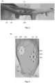
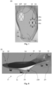
- an embodiment of an outsole 10 comprises a cushion element 20 being arranged in a forefoot area 11 of the outsole 10.
- Said cushion element 20 comprises a lattice structure 21.
- the outsole 10 comprises a sole element 30 comprising a receiving portion 31 by which the cushion element 20 is received.
- the receiving portion 31 is a recess being adapted to the shape of the cushion element 20, wherein the recess is arranged in a surface of the sole element 30 being opposite the running surface 17 of the outsole 10.
- the depth of the recess measured in a direction being perpendicular to a surface 50 on which the outsole 10 is to be placed during normal use substantially corresponds to the thickness of the cushion element 20.
- a support surface 16 being opposite the running surface 17 of the outsole 10 is jointly defined by a top surface 24 of the cushion element 20 and a top surface 32 of the sole element 30, wherein the top surface 24 of the cushion element 20 is substantially even with the top surface 32 of the sole element 30.
- the cushion element 20 comprises a first portion 22 and a second portion 23.
- Those portions 22, 23 are comprised by the lattice structure 21.
- the lattice structure 21, the first portion 22, and the second portion 23 are illustrated schematically.
- the indicated structure of the lattice structure 21 is not to be understood as a specific lattice configuration.
- the first portion 22 has a lower stiffness compared to the second portion 23.
- the first portion 22 has a lower stiffness measured in a direction being perpendicular to a surface 50 on which the outsole 10 is to be placed during normal use compared to the second portion 23.
- Said first portion 22 is arranged in an area of the outsole 10 which is configured to support the most medial Metatarsophalangeal joint. Moreover, the first portion 22 is located further medial relative to the second portion 23. In addition, the first portion 22 is located closer to the toe area 14 of the outsole 10 than the second portion 23. Even though not illustrated in the schematic lattice structures 21, the stiffness of the cushion element 20 measured in a direction being perpendicular to a surface 50 on which the outsole 10 is to be placed during normal use continuously increases from the first portion 22 to the second portion 23.
- the lattice structure 21 comprises a plurality of rod elements 25a, 25b, 25c, 26a, 26b, 26c.
- the rod elements 25a, 25b, 25c of the first portion 22 are arranged less densely than the rod elements 26a, 26b, 26c of the second portion 23.
- the rod elements 25a, 25b, 25c of the first portion 22 comprise a lower average diameter than the rod elements 26a, 26b, 26c of the second portion 23.
- Fig. 2 the rod elements 25a, 25b, 25c of the first portion 22 are arranged less densely than the rod elements 26a, 26b, 26c of the second portion 23.
- the rod elements 25a, 25b, 25c of the first portion 22 comprise a lower average diameter than the rod elements 26a, 26b, 26c of the second portion 23.
- the rod elements 25a, 25b, 25c of the first portion 22 are arranged less densely than the rod elements 26a, 26b, 26c of the second portion 23 and comprise a lower average diameter than the rod elements 26a, 26b, 26c of the second portion 23.
- the cushion element 20 is an insert element being attached to the sole element 30, e.g., by means of an adhesive and/or welding.
- the cushion element 20 comprises a bonding margin 27 which is integrally formed with the cushion element 20, e.g., by an additive manufacturing process.
- the cushion element 20 is arranged in an area 12 of the outsole 10 which is configured to support Metatarsal fat pads.
- the cushion element 20, as seen 18 from a heel area 15 of the outsole 10 may not extend substantially beyond an area 12 of the outsole 10 which is configured to support Metatarsal fat pads.
- the thickness of cushion element 20 measured in a direction being perpendicular to a surface 50 on which the outsole 10 is to be placed during normal use reaches a maximum in the area 12 which is configured to support Metatarsal fat pads and decreases towards the heel area 15 and the toe area 14.
- the cushion element 20 substantially extends from a lateral side of the outsole 10 to a medial side of the outsole 10. Furthermore, none of the depicted cushion elements 20 extends into the heel area 15 of the outsole 10.
- Fig. 9 illustrates that the bending stiffness of the sole element 30 relative to a bending axis which is perpendicular to the longitudinal direction of the outsole 10 and parallel to a surface 50 on which the outsole 10 is to be placed during normal use is smaller in the receiving portion 31 than compared to portions of the sole element 30 being adjacent to the receiving portion 31.
- said bending stiffness has a minimum in the receiving portion 31. Particularly, said minimum is located in a flex portion 37 of the sole element 30, wherein the flex portion 37 is the portion of the sole element 30 which experiences the maximum bending during running.
- Said flex portion 37 extends partially along the receiving portion 31.
- the flex portion 37 extends along the receiving portion 31 between the second row of studs 36b and the third row of studs 36c, as counted from the tip of the sole element 30.
- Figs. 4 and 9 illustrate that the sole element 30 comprises at least one aperture 33a, 33b, 33c, 34a, 34b which overlaps at least partially with the cushion element 20.
- the at least one aperture 33a, 33b, 33c, 34a, 34b comprises at least one bottom aperture 33a, 33b, 33c which is adapted such that the cushion element 20 (when arranged in the sole element 30) faces a surface 50 on which the outsole 10 is to be placed during normal use.
- the cushion element 20 when arranged in the sole element 30
- the cushion element 20 faces a surface 50 on which the outsole 10 is to be placed during normal use.
- the at least one aperture 33a, 33b, 33c, 34a, 34b comprises two side apertures 34a, 34b which are adapted such that the cushion element 20 (when arranged in the sole element 30) faces in a lateral direction of the outsole 10 and a medial direction of the outsole 10.
- the at least one bottom aperture 33a, 33b, 33c and the at least one side aperture 34a, 34b are covered by a transparent cover element 40.
- Fig. 3 shows that the sole element 30 comprises at least one stud 35a, 35b which overlaps with the cushion element 20.
- the sole element 30 comprises three rows of studs 36a, 36b, 36c, wherein between each pair of said rows of studs 36a, 36b, 36c at least one bottom aperture 33a, 33b, 33c as described in the foregoing is arranged.
Landscapes
- Health & Medical Sciences (AREA)
- General Health & Medical Sciences (AREA)
- Physical Education & Sports Medicine (AREA)
- Epidemiology (AREA)
- Public Health (AREA)
- Chemical & Material Sciences (AREA)
- Engineering & Computer Science (AREA)
- Materials Engineering (AREA)
- Footwear And Its Accessory, Manufacturing Method And Apparatuses (AREA)
Abstract
The present disclosure relates to an outsole (10) for a shoe, the outsole (10) comprising: a cushion element (20) being arranged in a forefoot area (11) of the outsole (10), wherein the cushion element (20) comprises a lattice structure (21), wherein the cushion element (20) comprises a first portion (22) and a second portion (23), wherein the first portion (22) has a lower stiffness compared to the second portion (23), and a sole element (30) comprising a receiving portion (31) by which the cushion element (20) is received.
Description
- The present disclosure relates to an outsole for a shoe and a shoe comprising said outsole.
- When designing outsoles for shoes and/or shoes, a compromise is often made between different properties that the outsole and/or the shoe should have. Exemplarily, a shoe, such as a football shoe, with a stiff outsole can provide outstanding properties for running with high speed, whereas the stiff outsole may however result in a reduced comfort. Hence, it is a fundamental objective to improve the overall properties of the outsole and/or the respective shoe. In this direction, the present invention aims to solve different problems.
- A first problem to which the present invention is directed is the aspect that outsoles for shoes, e.g., football shoes, which are optimized for fast running, i.e., sprinting, by means of a stiff material behavior regularly exhibit significant impairments for a wearer. Exemplarily, stiff outsoles can reduce comfortability for the wearer. Furthermore, stiff outsoles may reduce the feel for the ball since the overall flexibility of the shoe is reduced. Moreover, outsoles that exhibit linearly and/or homogeneously stiff behavior, may inhibit the wearer's ability to accelerate effectively due to limited metatarsal and/or toe flexion. This is exemplarily disadvantageous at a start of a sprint where more toe flexion is considered beneficial. Hence, in summary, a first objective according to the present invention is to provide an outsole which allows for fast running, i.e., sprinting, and at least partially avoids the above-mentioned drawbacks.
- A second problem to which the present invention is directed is the aspect that many sports require multiple sprints. Thereby, starting sprints on straight surfaces which may sometimes also be covered with grass and/or dirt proves to be difficult, even with studs. This is as there is no external object for pushing off as in sprinting in athletics, where starting blocks are regularly provided. Hence, a second objective according to the present invention is to provide an outsole for a shoe which enables an improved start of sprints and/or an improved pushing off in general.
- A third problem to which the present invention is directed is the aspect that shoes often have relatively flat and/or stiff outsoles that make it difficult, or at least not easy, for the foot to roll during walking, moderate running, and/or accelerating. However, it is also known that curved outsoles may lead to instability and/or limited ground contact. This is regularly not accepted for sports such as football, rugby, etc. Hence, a third objective according to the present invention is to provide an outsole which allows for improved walking and/or moderate running and at the same time at least partially avoids instability and/or limited ground contact.
- A fourth problem to which the present invention is directed is the aspect that outsoles for shoes which comprise a cushioning regularly do not allow the properties provided by the cushioning (e.g., damping, and/or cushioning) to be adapted without the outsole itself being changed. Thereby the adaption of outsoles, e.g., by changing the material and/or geometry, regularly comes with significant effort. Hence, a fourth objective according to the present invention is to overcome this drawback at least partially.
- Exemplary background prior art is mentioned in
US 6 601 321 B1 ,US 2021 / 0 037 908 A1 ,CN 2 13 154 354 U , andUS 2007 /0 017 122 A1 . - Therefore, in summary, an overall target of the present invention is to provide an outsole for a shoe and a shoe comprising said outsole which address and/or pursue the above problems and/or objectives at least partially.
- This overall target is achieved, at least partly, by an outsole for a shoe and a shoe comprising said outsole, as defined in the independent claims. Further aspects of the present disclosure are defined in the dependent claims.
- In particular, the overall target is achieved by an outsole for a shoe. The outsole comprises a cushion element being arranged in a forefoot area of the outsole, wherein the cushion element comprises a lattice structure, wherein the cushion element comprises a first portion and a second portion, wherein the first portion has a lower stiffness compared to the second portion. Further the outsole comprises a sole element comprising a receiving portion by which the cushion element is received.
- The stiffness may refer to the material stiffness, i.e., the young's modulus, the structural stiffness, and/or a combination thereof. Exemplarily, the first portion and the second portion may comprise the same material, i.e., have the same young's modulus, whereas the difference in stiffness is provided by the configuration of the lattice structure. Further exemplarily, the shape of the the first portion and the second portion may be identical, wherein the difference in stiffness is provided by the material selected for the first portion and the second portion. It is understood that a combination of those two examples is possible.
- Moreover, the stiffness of the first portion and the second portion may be measured in a direction being perpendicular to a surface on which the outsole is to be placed during normal use. Hence, the stiffness may be referred to as compressive stiffness. For measuring the stiffness, i.e., the compressive stiffness, of the first portion and the second portion a predefined force, e.g., 100 N, may be applied on the first portion in a vertical direction and on the second portion in a vertical direction respectively, wherein the term "vertical direction" in this regard refers to a direction being perpendicular to a surface on which the outsole is to be placed during normal use. Then a first change in height of the first portion caused by the predefined force may be identified and a second change in height of the second portion also caused by the predefined force may be identified. Subsequently the first change in height and the second change in height may be compared. If the second change in height is less than the first change in height, the first portion has a lower stiffness, i.e., compressive stiffness, compared to the second portion. It is understood that the first and/or second change in height may be defined as the height difference measured in the vertical direction between the unloaded state and the loaded state.
- The cushion element may be attached to the sole element, e.g. by gluing, welding, and/or stitching. The cushion element may comprise a substantially elastic material behaviour. Thus, the cushion element may allow for improved energy return to the wearer. However, the cushion element may also be viscoelastic, i.e., exhibit viscous behaviour and elastic behaviour simultaneously. This allows the cushion element to be adapted to load patterns that are typical for certain sports. Exemplarily, a soft cushion element may be desired when walking, i.e., at low load speeds, whereas a hard cushion element may be desired when sprinting is started, i.e., at high load speeds. In this regard it is understood that the cushion element may also comprise a material which has a strain rate dependent material behaviour.
- The forefoot area of the outsole may be referred to as the portion of the outsole which is configured to support the toes and the Metatarsal bones of the wearer. It is understood that the cushion element may be located only in a portion of the forefoot area. Further, the cushion element may extend beyond the forefoot area, e.g., into the toe area and/or the heel area.
- Details regarding the lattice structure are explained throughout the present disclosure. However, in general, the lattice structure favors specific local adjustment of properties without necessarily changing the material. Moreover, a visual inspection is facilitated, e.g., compared to foam material, so that material failure, e.g., caused by external forces or improper use, in the cushion element may be identified more easily.
- The aspect wherein the first portion has a lower stiffness compared to the second portion may refer to the first portion having a lower compressive stiffness compared to the second portion, measured in the thickness direction of the outsole.
- The aspect wherein the first portion has a lower stiffness compared to the second portion may further refer to the first portion having a lower bending stiffness compared to the second portion.
- Regarding the sole element it is to be noted that the outsole may comprise more than one sole element. Moreover, the sole element may comprise a plurality of layers. Exemplarily, the sole element may comprise a plurality of carbon fiber layers and/or glass fiber layers which are embedded in a polymer matrix. Nevertheless, the sole element may also be a single layer. The sole element does not need to be a closed layer but can also have a grid-like and/or frame-like structure. This may be particularly advantageous for a reduced weight of the outsole. Further, the sole element may comprise a polymer such as Polyamide 11 (PA 11) and/or Polyamide 12 (PA 12). Further, the sole element may comprise a thermoplastic elastomer (TPE) such as polyether block amide (PEBA) and/or thermoplastic polyurethane (TPU). Furthermore, the sole element may be at least partially formed by injection molding. Exemplarily, a layer may be molded or a grid-like and/or frame-like support structure may be overmolded. Further, composite materials, such as carbon fiber reinforced polymers, glass fiber reinforced polymers and/or other reinforced materials, may be comprised by the sole element. Moreover, the sole element may be at least partially formed by additive manufacturing methods (e.g., 3D printing methods) and/or composite processing methods.
- The outsole according to the present disclosure may provide various advantages and/or fulfil different tasks.
- First, the cushion element may serve to increase the thickness of the outsole such that the second moment of area of the outsole can be locally increased, particularly without excessively increasing the weight. Hence, the bending stiffness may be locally adapted. Further, by means of the first and second portion the compressive stiffness of the outsole may be locally adapted by means of the cushion element. Thus, in summary, it is possible to adjust the stiffness of the outsole in various respects while keeping the weight low.
- Second, the cushion element may serve to precisely cushion sections of a wearer's foot and thereby increase comfort. Particularly, by means of the first and second portion with different stiffness. As a result, the sole element can be made thinner, thus saving weight without reducing comfort.
- Third, the cushion element may serve as an "integrated starting block" for the wearer which enables an improved start of sprints, i.e., allows for better pushing off. This is as the cushion element makes it possible that an elevation is formed, e.g., on a ground-facing surface of the outsole, which allows for better pushing off. Particularly by the first and second portion with different stiffness the functionality as "integrated starting block" can be precisely adjusted and/or implemented.
- Fourth, the cushion element may provide a "rocker effect" to the outsole. Rocker outsole designs are known for medical purposes, e.g., for reducing forefoot plantar pressures for people with diabetes, but also for increasing comfort of leisure shoes. However, the "rocker effect" may be particularly advantageous for outsoles with improved running properties, e.g., for outsoles of football shoes. As in the previous paragraph, the cushion element makes it possible that an elevation is formed, particularly on a ground-facing surface of the outsole. Hence, a portion of a running surface of the outsole may be elevated such that a rolling effect, i.e., "rocker effect" is created. This can have a positive effect on performance because the wearer must exert less force to overcome a pivot point, i.e., to roll the foot, during walking and/or, moderate running, and/or accelerating. Thereby, accelerating may particularly refer to an acceleration from an essentially standing position of the wearer. This is as particularly when accelerating from a standing position the "rocker effect" may contribute to said positive effect on performance.
- It is understood that the cushion element serving as an "integrated starting block" may at the same time provide a "rocker effect" to the outsole. Further, since the cushion element may serve as the "integrated starting block" and/or provide the "rocker effect", its compression properties may allow that during high and/or vertical loading conditions, e.g., during sprinting, a disadvantageous influence, i.e., instability, due to the elevation of the outsole is avoided.
- Fifth, the cushion element allows that the properties (e.g., damping, and/or cushioning) of the outsole can be adapted to a particular wearer without the sole element itself being changed.
- The skilled person understands that the above-described advantages may also apply for the following embodiments in different emphasis.
- The first portion may be located further medial relative to the second portion. It has been found that by arranging the first portion further medially, the "integrated starting block" effect can be further improved, while at the same time the stability of the outsole is not negatively influenced. A more medial location may cause the Metatarsophalangeal joints to be pressed into the cushion element more easily than other parts of the foot which improves pushing-off while the lateral parts of the cushion element have a stabilizing effect.
- The first portion may be arranged in an area of the outsole which is configured to support the most medial Metatarsophalangeal joint. This configuration allows the most medial Metatarsophalangeal joint to be pressed into the cushion element more easily than other parts of the foot which is assumed to allow for a better pushing-off. This can further improve the functionality of the outsole as an "integrated starting block" for the wearer. Summarizing this allows the outsole to provide a better start to sprints.
- Alternatively, the first portion may be located further lateral relative to the second portion. By arranging the first portion further laterally, the "integrated starting block" effect can be used to improve pushing-off during movements towards a lateral direction.
- The receiving portion may be a recess being adapted to the shape of the cushion element, wherein preferably the recess is arranged in a surface of the sole element being opposite the running surface of the outsole. This configuration has proven advantageous in that an outsole with specifically adapted properties can be provided with a reduced number of components. Moreover, with the recess being arranged in a surface of the sole element being opposite the running surface of the outsole, both the bending stiffness of the outsole and the compressive stiffness of the outsole can be precisely adjusted depending on the selected cushion element.
- The depth of the recess measured in a direction being perpendicular to a surface on which the outsole is to be placed during normal use may substantially correspond to the thickness of the cushion element. This can avoid the need to compensate for height differences by means of additional components.
- The cushion element may be an insert element being attached to the sole element, preferably by means of an adhesive, welding, and/or stitching. The term "insert element" may refer to the aspect that the cushion element was put into the sole element. The cushion element being an insert element may allow the outsole to be provided with low manufacturing tolerances. Especially compared to outsoles where layers are manually stacked. In addition, the cushion element being an insert element can be stably retained in the sole element.
- A support surface being opposite the running surface of the outsole may be jointly defined by a top surface of the cushion element and a top surface of the sole element. The support surface can fully or at least partially support the wearer's foot directly or indirectly, e.g., when other layers are placed over the support surface. Hence, this configuration may allow to provide a support surface that can fully support the wearer's foot with specifically set properties using a sole element and a cushion element, i.e., with few components.
- Further, the top surface of the cushion element may be substantially even with the top surface of the sole element. The functionality enabled by this feature lies in that an unevenness can be avoided, which might be perceived as uncomfortable by the wearer of the shoe. Especially, without the need to provide further measures that would compensate for such unevenness.
- Moreover, the outsole may further comprise a cover plate, wherein the cushion element preferably is sandwiched between the sole element and the cover plate. This configuration can be used to connect a shoe upper to the outsole. For example, the shoe upper can be clamped between the sole element and the cover plate. Thus, this configuration of the outsole can allow for the completion of a shoe with few components.
- The cover plate may extend along the full length of the outsole, only along the forefoot area of the outsole, only along the midfoot area of the outsole, or only along the length of the cushion element. The midfoot area of the outsole may be referred to as the portion of the outsole which is configured to support the Metatarsal bones of the wearer. Thereby, it is understood that the Metatarsophalangeal joints may be considered as part of the forefoot, however not as part of the midfoot.
- The bending stiffness of the sole element relative to a bending axis which is perpendicular to the longitudinal direction of the outsole and parallel to a surface on which the outsole is to be placed during normal use may be smaller in the receiving portion than compared to portions of the sole element being adjacent to the receiving portion. Further, said bending stiffness of the sole element may have a minimum in the receiving portion. Preferably said minimum is located in a flex portion of the sole element. The flex portion may be referred to as the portion of the sole element which experiences the maximum bending during running. Moreover, the flex portion may extend at least partially along the receiving portion. The above configurations allow the bending stiffness of the outsole in the receiving portion to be primarily and/or precisely adjusted by the selected cushion element. Accordingly, an outsole with precisely set properties can be provided depending on the selected cushion element.
- The cross-sectional area of the receiving portion measured in a plane being perpendicular to the longitudinal direction of the outsole may be smaller than compared to portions of the sole element being adjacent to the receiving portion. This allows the properties (compressive stiffness, bending stiffness, cushioning, damping, etc.) of the outsole in the receiving portion to be primarily and/or precisely adjusted by the selected cushion element. Hence, an outsole with precisely set properties can be provided depending on the selected cushion element. In particular, the cross-sectional area of the flex portion measured in a plane being perpendicular to the longitudinal direction of the outsole may be smaller than compared to portions of the sole element being adjacent to the flex portion.
- The cushion element may be arranged in an area of the outsole which is configured to support Metatarsal fat pads. By this configuration an elevation may be formed, e.g., on a ground-facing surface of the outsole, which particularly allows better pushing off. Hence, this elevation may serve as an "integrated starting block" for the wearer. Thus, the outsole may allow for an improved start of sprints.
- The thickness of the cushion element measured in a direction being perpendicular to a surface on which the outsole is to be placed during normal use may reach a maximum in the area which is configured to support Metatarsal fat pads and preferably decreases towards the heel area and/or the toe area. This configuration particularly allows the cushion element to serve as an "integrated starting block" for the wearer while providing the above-mentioned "rocker effect". Further, it is possible to improve damping and/or increase bending stiffness where it is deemed particularly necessary by the inventors. In addition, a continuous profile of the properties of the outsole is ensured. For example, jumps in stiffness are avoided. Furthermore, said maximum thickness may lie in the range from 1 mm to 20 mm, preferably from 2 mm to 10 mm. These thicknesses have proven to be beneficial, as they sufficiently improve cushioning and/or increase bending stiffness without adding too much material, i.e. weight, to the outsole. Further, these thicknesses allow that the cushion element may serve as an "integrated starting block" for the wearer which enables an improved start of sprints, i.e. allows for better pushing off, without causing instability due to the wearer being raised excessively away from the ground. Even further, these thicknesses have proven to be sufficient for providing the above-mentioned "rocker effect".
- The first portion and second portion may each comprise a first undeformed height and a second undeformed height (i.e., the distance between the top surface and bottom surface of the cushion element) that are equal. The first portion may comprise a first undeformed height and the second portion may comprise a second undeformed height being less than the first undeformed height.
- The above-mentioned second change in height may lie in a range from 10% to 95% of the above-mentioned first change in height, preferably from 30% to 60% of the first change of height. These ranges have proven to be beneficial, as they allow that the cushion element may serve as an "integrated starting block" for the wearer which enables an improved start of sprints, i.e., allows for better pushing off, without causing instability due to the wearer being raised excessively away from the ground.
- According to the present disclosure the toe area of the outsole may be referred to as the portion of the outsole which is configured to support the toes of the wearer. Generally, it is understood that the midfoot of the wearer may be separated from the toe portion at the Metatarsophalangeal joints.
- The cushion element may substantially extend from a lateral side of the outsole to a medial side of the outsole. This allows the properties of the outsole to be specifically and continuously adjusted across the width of the outsole.
- Alternatively, the cushion element may extend partially between the lateral side and the medial side. The cushion element may not extend in a non-cushioned portion of the sole. The cushion element may comprise a lower stiffness than the non-cushioned portion. The cushion element may be located further medial or further lateral than the non-cushioned portion. Hence, this alternative allows that the cushion element in combination with the non-cushioned portion may serve as an "integrated starting block" for the wearer which enables an improved start of sprints, i.e., allows for better pushing off, without causing instability due to the wearer being raised excessively away from the ground.
- The lattice structure may comprise a plurality of rod elements. Said rod elements can be connected at respective nodal points. However, alternative configurations are also conceivable. Exemplarily, the rod elements may extend between two opposing surfaces and be supported by these surfaces.
- The rod elements of the first portion may comprise a lower average diameter than the rod elements of the second portion. In this way, a specific adjustment of the stiffness of the cushion element can be achieved without changing the material and/or the arrangement of the rod elements. Among other aspects, this can facilitate recycling, improve manufacturing, allow for continuously changing properties, and/or avoid a complex arrangement of the rod elements.
- Further, the rod elements of the first portion may be arranged less densely than the rod elements of the second portion. In this way, a specific adjustment of the stiffness of the cushion element can be achieved without changing the material and/or the diameter of the rod elements. This may also facilitate recycling, improve manufacturing, and/or allow for continuously changing properties.
- It is understood that the rod elements of the first portion may comprise a lower average diameter than the rod elements of the second portion and/or the rod elements of the first portion may be arranged less densely than the rod elements of the second portion.
- Moreover, the first portion may be located closer to the toe area of the outsole than the second portion. In this regard it was found that particularly a combination with the above-mentioned configuration, wherein the first portion is located further medial relative to the second portion, the "integrated starting block" effect can be even further improved, while the stability of the outsole is not negatively influenced. Furthermore, by the first portion being located closer to the toe area of the outsole than the second portion it may be ensured that sufficient toe flexibility is given what is essential for various sports such as football/soccer.
- The stiffness of the cushion element measured in a direction being perpendicular to a surface on which the outsole is to be placed during normal use may continuously increase from the first portion to the second portion. This makes it possible to avoid stiffness jumps that are perceived as annoying by the wearer and/or are functionally disadvantageous.
- The cushion element may comprise a bonding margin, wherein the bonding margin is preferably integrally formed with the cushion element. This allows the cushion element to be attached to the sole element, e.g., by an adhesive. By the bonding margin being integrally formed with the cushion element the number of parts of the outsole may be maintained low.
- The cushion element may be manufactured by an additive manufacturing process. Manufacturing the cushion element by additive manufacturing processes, such as 3D-printing, has proven to be advantageous because they allow complex structures and/or anisotropic material behavior. Thus, the geometry and/or properties of the outsole can be precisely adapted. In addition, outsoles with properties individually adapted to a particular wearer can be realized.
- The sole element may comprise at least one aperture which overlaps at least partially with the cushion element. First, the at least one aperture may enhance visual inspection so that material failure, e.g., caused by external forces or improper use, in the cushion element may be identified more easily. Second, the at least one aperture may serve to adapt the stiffness of the sole element. Third, the at least one aperture may also serve to adapt the compression properties of the cushion element with which the aperture overlaps. It is understood that the at least one aperture in the sole element not necessarily requires a closed contour. Nevertheless, the at least one aperture may comprise a closed contour in the sole element. Thereby the stability of the at least one aperture may be increased. The at least one aperture may be a cut-out opening. Further, the at least one aperture may be an integrally formed opening, e.g. by means of injection moulding.
- The at least one aperture may comprise at least one bottom aperture which is adapted such that the cushion element faces a surface on which the outsole is to be placed during normal use. The at least one bottom aperture may serve to locally reduce and/or adapt the stiffness of the outsole, i.e. of the sole element.
- The at least one aperture may comprise at least one side aperture which is adapted such that the cushion element faces in a lateral direction of the outsole and/or a medial direction of the outsole, wherein preferably the at least one aperture comprises at least two side apertures which are adapted such that the cushion element faces in a lateral direction of the outsole and a medial direction of the outsole. The at least one side aperture may allow for adapting the stiffness of the cushion element with which the aperture overlaps. Particularly, the at least one side aperture may allow for adapting the compressive stiffness. This is as a vertical compression of the cushion element is at least locally not limited by material of the sole element. Rather, a substantially free compression of the cushion element is possible until the side aperture is closed. The term "vertical" in this regard refers to a direction which is perpendicular to a surface on which the outsole is to be placed during normal use.
- The at least one aperture may be covered by a cover element. This allows the cushion element to be protected from dirt and/or environmental influences such as moisture which may negatively impact the functionality of the cushion element.
- The at least one bottom aperture and the at least one side aperture may be covered by the cover element. This allows the cover element to be arranged in a particularly fixed position in the sole element and the apertures to be closed with just one component.
- The cover element may be a transparent cover element. This allows the cushion element to be visually inspected so that material failure, e.g., caused by external forces or improper use, in the cushion element may be identified and at the same time the cushion element is protected from dirt and/or potentially harmful environmental influences.
- The cover element may comprise a lower stiffness compared to the sole element. Further, the cover element may comprise a material with less stiffness and/or hardness compared to the material of the sole element. This helps to minimize the impact of the cover element on the functionality of the sole element and the cushion element.
- The cushion element may be at least partially enclosed by a foil, wherein the foil is preferably transparent. This also allows the cushion element to be visually inspected so that material failure, e.g., caused by external forces or improper use, in the cushion element may be identified and at the same time the cushion element is protected from dirt and/or potentially harmful environmental influences.
- The sole element may comprise at least one stud wherein the at least one stud overlaps with the cushion element. Studs according to the present invention, which may be also referred to as cleats, may serve to provide traction for the wearer on soft grounds such as grass fields. The use of studs is known from the field of football, i.e., soccer, American football, rugby and/or athletics. The studs can be integrally formed with the sole element. Further, the studs may be at least partially (e.g., the tips of the studs) injected onto a base material. Moreover, the studs may be formed by placing prefabricated stud tips in a mold and over-injecting them with at least a part of the outsole (e.g., a plate and/or a base material). The base material may comprise the sole element. Moreover, the studs may be based on TPU. The above-mentioned eliminates the need to screw on and/or replace the studs. However, interchangeable studs or screwon studs can also be used. Accordingly, studs of different lengths and/or materials can be used for different ground conditions. Since the cushion element overlaps with at least one stud it may be avoided to transfer uncomfortable pressure from the stud/s to the wearer's foot. As a result, the sole element can be made thinner, thus saving weight without reducing comfort.
- The sole element may comprise at least two rows of studs, wherein the at least one bottom aperture, as described above, may be arranged between said rows of studs, wherein preferably the sole element comprises at least three rows of studs, wherein between each pair of said rows of studs at least one bottom aperture, as described above, is arranged. This configuration allows the bending stiffness and/or the compressive stiffness of the outsole to be selectively adjusted by the at least one bottom aperture, while at the same time the studs are reliably attached to the outsole. In addition, the cushion element can be inspected more easily.
- The cushion element optionally does not extend into the heel area of the outsole. This makes it possible to make the heel area of the outsole more stable than when the cushion element extends into the heel area. This allows the risk of injury, for example due to twisting, to be reduced.
- The cushion element, as seen from a heel area of the outsole, optionally does not extend substantially beyond an area of the outsole which is configured to support Metatarsal fat pads. Hence, an increased stiffness of the outsole beyond said area is avoided. This is as the cushion element in said area does not increase the second moment of area of the outsole. Thus, toe flexion may be enhanced which is advantageous at the start of a sprint where more toe flexion is beneficial. The term "substantially" may refer to the aspect that the cushion element as seen from the heel portion of the outsole does not extend beyond the area of the outsole which is configured to support Metatarsal fat pads by more than 1 cm, and optionally 0.5 cm.
- The outsole may comprise a plurality of cushion elements as specified above. For example, the cushion elements may be stacked on top of each other. Moreover, the cushion elements may be stacked in a stacking direction extending from a medial part of the outsole to a lateral part of the outsole or in the opposite direction.
- The first portion may have a lower stiffness measured in a direction being perpendicular to a surface on which the outsole is to be placed during normal use compared to the second portion.
- According to an alternative embodiment the above-described cushion element may comprise a foam material and/or a gel material instead or in addition to the lattice structure. It is understood for this alternative embodiment the features and/or advantages described above may also apply. Foam materials have proven to be beneficial since they allow for a compromise between damping, i.e., comfort, and elasticity, i.e., energy recovery. The foam material may comprise a polyamide, a polyether block amide, an expanded polyether block amide, a thermoplastic polyurethane, an expanded thermoplastic polyurethane, ethylene vinyl acetate (EVA), thermoset polyurethane foam, and/or a thermoplastic co-polyester. Furthermore, the foam material may be manufactured in a particular process to achieve advantageous properties. Exemplarily, utilising a particle foam has been shown to be advantageous in the sporting goods industry, as exemplarily described in
US 2014/366405 A1 andUS 2018/035755 A1 . Thereby compact polymer granules are foamed to form expanded foam beads. These beads are then joined together at their surfaces by means of applying heat that at least partially melts the particle surfaces. For example, Steam Chest Moulding and/or Radio Frequency Fusion may be applied therefor. Other specific process adaptations can also be advantageous. For example, a gaseous blowing agent in an autoclave/extrusion/injection moulding process maybe replaced by a blowing agent in a supercritical state. Furthermore, gel materials have proven to be advantageous since they allow for a particularly good damping. - Further, the above-mentioned overall target is achieved by a shoe, in particular a football/soccer shoe, comprising the outsole as described herein. It will be understood that the advantages as described above with reference to the outsole also apply for the shoe.
- In the following, the accompanying figures are briefly described:
-
Fig. 1 shows a side-view of an outsole according to the present invention; -
Fig. 2 shows a top-view of another outsole according to the present invention; -
Fig. 3 shows a bottom-view of the outsole ofFig. 2 ; -
Fig. 4 shows a top-view of the outsole ofFig. 2 being disassembled; -
Fig. 5 shows a side-view of the front part of the outsole ofFig. 2 without the cushion element; -
Fig. 6 shows a top-view of a cushion element for an outsole according to the present invention; -
Fig. 7 shows a top-view of another cushion element for an outsole according to the present invention; -
Fig. 8 shows a perspective view of another outsole according to the present invention; -
Fig. 9 corresponds toFig. 8 with the cushion element being removed, and -
Fig. 10 shows a perspective view of a cover element of an outsole according to the present invention. - In the following, preferred embodiments of the present invention are described with reference to the figures. As depicted in
Figs. 1, 2 ,3 and 4 , an embodiment of anoutsole 10 according to the invention comprises acushion element 20 being arranged in aforefoot area 11 of theoutsole 10. Saidcushion element 20 comprises alattice structure 21. Further, theoutsole 10 comprises asole element 30 comprising a receivingportion 31 by which thecushion element 20 is received. - According to
Figs. 1, 2 ,4 , and9 , the receivingportion 31 is a recess being adapted to the shape of thecushion element 20, wherein the recess is arranged in a surface of thesole element 30 being opposite the runningsurface 17 of theoutsole 10. Particularly, and as shown inFigs. 2 and8 , the depth of the recess measured in a direction being perpendicular to asurface 50 on which theoutsole 10 is to be placed during normal use substantially corresponds to the thickness of thecushion element 20. Moreover, asupport surface 16 being opposite the runningsurface 17 of theoutsole 10 is jointly defined by atop surface 24 of thecushion element 20 and atop surface 32 of thesole element 30, wherein thetop surface 24 of thecushion element 20 is substantially even with thetop surface 32 of thesole element 30. - Further, as shown in
Figs. 2 ,4 ,6 , and7 , thecushion element 20 comprises afirst portion 22 and asecond portion 23. Thoseportions lattice structure 21. In this regard it is to be noted that in any of the figures thelattice structure 21, thefirst portion 22, and thesecond portion 23 are illustrated schematically. Particularly, the indicated structure of thelattice structure 21 is not to be understood as a specific lattice configuration. Thefirst portion 22 has a lower stiffness compared to thesecond portion 23. In detail, thefirst portion 22 has a lower stiffness measured in a direction being perpendicular to asurface 50 on which theoutsole 10 is to be placed during normal use compared to thesecond portion 23. Saidfirst portion 22 is arranged in an area of theoutsole 10 which is configured to support the most medial Metatarsophalangeal joint. Moreover, thefirst portion 22 is located further medial relative to thesecond portion 23. In addition, thefirst portion 22 is located closer to thetoe area 14 of theoutsole 10 than thesecond portion 23. Even though not illustrated in theschematic lattice structures 21, the stiffness of thecushion element 20 measured in a direction being perpendicular to asurface 50 on which theoutsole 10 is to be placed during normal use continuously increases from thefirst portion 22 to thesecond portion 23. - Moreover, as also shown in
Figs. 2 ,6 , and7 , thelattice structure 21 comprises a plurality ofrod elements Fig. 2 therod elements first portion 22 are arranged less densely than therod elements second portion 23. InFig. 6 therod elements first portion 22 comprise a lower average diameter than therod elements second portion 23. Moreover, inFig. 7 therod elements first portion 22 are arranged less densely than therod elements second portion 23 and comprise a lower average diameter than therod elements second portion 23. - Furthermore, particularly from
Figs. 2 and4 the skilled person understands that thecushion element 20 is an insert element being attached to thesole element 30, e.g., by means of an adhesive and/or welding. In this regard thecushion element 20 comprises abonding margin 27 which is integrally formed with thecushion element 20, e.g., by an additive manufacturing process. - As depicted in
Figs. 1, 2 , and8 , thecushion element 20 is arranged in anarea 12 of theoutsole 10 which is configured to support Metatarsal fat pads. Thereby, as particularly shown inFig. 1 , thecushion element 20, as seen 18 from aheel area 15 of theoutsole 10, may not extend substantially beyond anarea 12 of theoutsole 10 which is configured to support Metatarsal fat pads. Further, the thickness ofcushion element 20 measured in a direction being perpendicular to asurface 50 on which theoutsole 10 is to be placed during normal use reaches a maximum in thearea 12 which is configured to support Metatarsal fat pads and decreases towards theheel area 15 and thetoe area 14. Even further, as particularly shown inFig. 2 , thecushion element 20 substantially extends from a lateral side of theoutsole 10 to a medial side of theoutsole 10. Furthermore, none of the depictedcushion elements 20 extends into theheel area 15 of theoutsole 10. -
Fig. 9 illustrates that the bending stiffness of thesole element 30 relative to a bending axis which is perpendicular to the longitudinal direction of theoutsole 10 and parallel to asurface 50 on which theoutsole 10 is to be placed during normal use is smaller in the receivingportion 31 than compared to portions of thesole element 30 being adjacent to the receivingportion 31. Further, said bending stiffness has a minimum in the receivingportion 31. Particularly, said minimum is located in aflex portion 37 of thesole element 30, wherein theflex portion 37 is the portion of thesole element 30 which experiences the maximum bending during running. Saidflex portion 37 extends partially along the receivingportion 31. In more detail, theflex portion 37 extends along the receivingportion 31 between the second row ofstuds 36b and the third row ofstuds 36c, as counted from the tip of thesole element 30. -
Figs. 4 and9 illustrate that thesole element 30 comprises at least oneaperture cushion element 20. Particularly, as shown in said figures, the at least oneaperture bottom aperture surface 50 on which theoutsole 10 is to be placed during normal use. Further particularly, as also shown inFigs. 4 and9 , the at least oneaperture side apertures outsole 10 and a medial direction of theoutsole 10. In addition, as the skilled person understands fromFig. 4 andFig. 9 together withFig. 10 that the at least onebottom aperture side aperture transparent cover element 40. -
Fig. 3 shows that thesole element 30 comprises at least onestud cushion element 20. Particularly, thesole element 30 comprises three rows ofstuds studs bottom aperture -
- 10
- outsole
- 11
- forefoot area
- 12
- area for supporting Metatarsal fat pads
- 13
- midfoot area
- 14
- toe area
- 15
- heel area
- 16
- support surface of the outsole
- 17
- running surface of the outsole
- 18
- view direction from a heel portion
- 20
- cushion element
- 21
- lattice structure
- 22
- first portion of the cushion element
- 23
- second portion of the cushion element
- 24
- top surface of the cushion element
- 25a, 25b, 25c
- rod elements of the first portion
- 26a, 26b, 26c
- rod elements of the second portion
- 27
- bonding margin
- 30
- sole element
- 31
- receiving portion of the sole element
- 32
- top surface of the sole element
- 33a, 33b, 33c
- bottom apertures
- 34a, 34b
- side apertures
- 35a, 35b
- studs
- 36a, 36b, 36c
- rows of studs
- 37
- flex portion
- 40
- cover element
- 50
- surface on which the outsole is to be placed during normal use
- In the following, exemplary embodiments are described to facilitate understanding the invention.
- 1. Outsole (10) for a shoe, the outsole (10) comprising:
- a cushion element (20) being arranged in a forefoot area (11) of the outsole (10), wherein the cushion element (20) comprises a lattice structure (21), wherein the cushion element (20) comprises a first portion (22) and a second portion (23), wherein the first portion (22) has a lower stiffness compared to the second portion (23), and
- a sole element (30) comprising a receiving portion (31) by which the cushion element (20) is received.
- 2. The outsole (10) according to the preceding embodiment, wherein the first portion (22) is located further medial relative to the second portion (23).
- 3. The outsole (10) according to any one of the preceding embodiments, wherein the first portion (22) is arranged in an area of the outsole (10) which is configured to support the most medial Metatarsophalangeal joint.
- 4. The outsole (10) according to any one of the preceding embodiments, wherein the receiving portion (31) is a recess being adapted to the shape of the cushion element (20), wherein preferably the recess is arranged in a surface of the sole element (30) being opposite the running surface (17) of the outsole (10).
- 5. The outsole (10) according to the preceding embodiment, wherein the depth of the recess measured in a direction being perpendicular to a surface (50) on which the outsole (10) is to be placed during normal use substantially corresponds to the thickness of the cushion element (20).
- 6. The outsole (10) according to one of the preceding embodiments, wherein the cushion element (20) is an insert element being attached to the sole element (30), preferably by means of an adhesive and/or welding.
- 7. The outsole (10) according to one of the preceding embodiments, wherein a support surface (16) being opposite the running surface (17) of the outsole (10) is jointly defined by a top surface (24) of the cushion element (20) and a top surface (32) of the sole element (30).
- 8. The outsole (10) according to the preceding embodiment, wherein the top surface (24) of the cushion element (20) is substantially even with the top surface (32) of the sole element (30).
- 9. The outsole (10) according to one of the preceding embodiments, wherein the outsole (10) further comprises a cover plate, wherein the cushion element (20) is sandwiched between the sole element (30) and the cover plate.
- 10. The outsole (10) according to the preceding embodiment, wherein the cover plate extends along the full length of the outsole (10), only along the forefoot area (11) of the outsole (10), only along the midfoot area (13) of the outsole (10), or only along the length of the cushion element (20).
- 11. The outsole (10) according to one of the preceding embodiments, wherein the bending stiffness of the sole element (30) relative to a bending axis which is perpendicular to the longitudinal direction of the outsole (10) and parallel to a surface (50) on which the outsole (10) is to be placed during normal use is smaller in the receiving portion (31) than compared to portions of the sole element(30) being adjacent to the receiving portion (31), wherein preferably said bending stiffness has a minimum in the receiving portion (31), wherein further preferably said minimum is located in a flex portion (37) of the sole element (30).
- 12. The outsole (10) according to one of the preceding embodiments, wherein the cross-sectional area of the receiving portion (31) measured in a plane being perpendicular to the longitudinal direction of the outsole (10) is smaller than compared to portions of the sole element (30) being adjacent to the receiving portion (31).
- 13. The outsole (10) according to one of the preceding embodiments, wherein the cushion element (20) is arranged in an area (12) of the outsole (10) which is configured to support Metatarsal fat pads.
- 14. The outsole (10) according to the preceding embodiment, wherein the thickness of cushion element (20) measured in a direction being perpendicular to a surface (50) on which the outsole (10) is to be placed during normal use reaches a maximum in the area (12) which is configured to support Metatarsal fat pads and preferably decreases towards the heel area (15) and/or the toe area (14).
- 15. The outsole (10) according to one of the preceding embodiments, wherein the cushion element (20) substantially extends from a lateral side of the outsole (10) to a medial side of the outsole (10).
- 16. The outsole (10) according to one of the preceding embodiments, wherein the lattice structure (21) comprises a plurality of rod elements (25a, 25b, 25c, 26a, 26b, 26c).
- 17. The outsole (10) according to the preceding embodiment, wherein the rod elements (25a, 25b, 25c) of the first portion (22) comprise a lower average diameter than the rod elements (26a, 26b, 26c) of the second portion (23)
- 18. The outsole (10) according to one of
embodiments 16 to 17, wherein the rod elements (25a, 25b, 25c) of the first portion (22) are arranged less densely than the rod elements (26a, 26b, 26c) of the second portion (23). - 19. The outsole (10) according to one of the preceding embodiments, wherein the first portion (22) is located closer to the toe area (14) of the outsole (10) than the second portion (23).
- 20. The outsole (10) according to one of the preceding embodiments, wherein the stiffness of the cushion element (20) measured in a direction being perpendicular to a surface (50) on which the outsole (10) is to be placed during normal use continuously increases from the first portion (22) to the second portion (23).
- 21. The outsole (10) according to one of the preceding embodiments, wherein the cushion element (20) comprises a bonding margin (27), wherein the bonding margin (27) is preferably integrally formed with the cushion element (20).
- 22. The outsole (10) according to one of the preceding embodiments, wherein the cushion element (20) is manufactured by an additive manufacturing process.
- 23. The outsole (10) according to one of the preceding embodiments, wherein the sole element (30) comprises at least one aperture (33a, 33b, 33c, 34a, 34b) which overlaps at least partially with the cushion element (20).
- 24. The outsole (10) according to the preceding embodiment, wherein the at least one aperture (33a, 33b, 33c, 34a, 34b) comprises at least one bottom aperture (33a, 33b, 33c) which is adapted such that the cushion element (20) faces a surface (50) on which the outsole (10) is to be placed during normal use.
- 25. The outsole (10) according to one of
embodiments 23 to 24, wherein the at least one aperture (33a, 33b, 33c, 34a, 34b) comprises at least one side aperture (34a, 34b) which is adapted such that the cushion element (20) faces in a lateral direction of the outsole (10) and/or a medial direction of the outsole (10), wherein preferably the at least one aperture (33a, 33b, 33c, 34a, 34b) comprises at least two side apertures (34a, 34b) which are adapted such that the cushion element (20) faces in a lateral direction of the outsole (10) and a medial direction of the outsole (10). - 26. The outsole (10) according to one of
embodiments 23 to 25, wherein the at least one aperture (33a, 33b, 33c, 34a, 34b) is covered by a cover element (40). - 27. The outsole (10) according to
embodiments - 28. The outsole (10) according to one of
embodiments 26 to 27, wherein the cover element (40) is a transparent cover element (40). - 29. The outsole (10) according to one of the preceding embodiments, wherein the cushion element (20) is at least partially enclosed by a foil, wherein the foil is preferably transparent.
- 30. The outsole (10) according to one of the preceding embodiments, wherein the sole element (30) comprises at least one stud (35a, 35b) wherein the at least one stud (35a, 35b) overlaps with the cushion element (20).
- 31. The outsole (10) according to the preceding embodiment, wherein the sole element (30) comprises at least two rows of studs (36a, 36b, 36c), wherein the at least one bottom aperture (33a, 33b, 33c) according to
embodiment 24 is arranged between said rows of studs (36a, 36b, 36c), wherein preferably the sole element (30) comprises at least three rows of studs (36a, 36b, 36c), wherein between each pair of said rows of studs (36a, 36b, 36c) at least one bottom aperture (33a, 33b, 33c) according toembodiment 24 is arranged. - 32. The outsole (10) according to one of the preceding embodiments, wherein the cushion element (20) does not extend into the heel area (15) of the outsole (10).
- 33. The outsole (10) according to one of the preceding embodiments, wherein the cushion element (20), as seen (18) from a heel area (15) of the outsole (10), does not extend substantially beyond an area (12) of the outsole (10) which is configured to support Metatarsal fat pads.
- 34. The outsole (10) according to one of the preceding embodiments, wherein the outsole (10) comprises a plurality of cushion elements (20) as specified in the preceding embodiments.
- 35. The outsole (10) according to one of the preceding embodiments, wherein the first portion (22) has a lower stiffness measured in a direction being perpendicular to a surface (50) on which the outsole (10) is to be placed during normal use compared to the second portion (23).
- 36. Shoe comprising the outsole (10) according to one of the preceding embodiments.
- 37. The shoe according to the preceding embodiment, wherein the shoe is a football shoe.
Claims (15)
- Outsole (10) for a shoe, the outsole (10) comprising:a cushion element (20) being arranged in a forefoot area (11) of the outsole (10), wherein the cushion element (20) comprises a lattice structure (21), wherein the cushion element (20) comprises a first portion (22) and a second portion (23), wherein the first portion (22) has a lower stiffness compared to the second portion (23), anda sole element (30) comprising a receiving portion (31) by which the cushion element (20) is received.
- The outsole (10) according to the preceding claim, wherein the first portion (22) is located further medial relative to the second portion (23), preferably, wherein the first portion (22) is arranged in an area of the outsole (10) which is configured to support the most medial Metatarsophalangeal joint.
- The outsole (10) according to any one of the preceding claims, wherein the receiving portion (31) is a recess being adapted to the shape of the cushion element (20), wherein preferably the recess is arranged in a surface of the sole element (30) being opposite the running surface (17) of the outsole (10), preferably, wherein the depth of the recess measured in a direction being perpendicular to a surface (50) on which the outsole (10) is to be placed during normal use substantially corresponds to the thickness of the cushion element (20).
- The outsole (10) according to one of the preceding claims, wherein the cushion element (20) is an insert element being attached to the sole element (30), preferably by means of an adhesive and/or welding.
- The outsole (10) according to one of the preceding claims, wherein a support surface (16) being opposite the running surface (17) of the outsole (10) is jointly defined by a top surface (24) of the cushion element (20) and a top surface (32) of the sole element (30), preferably, wherein the top surface (24) of the cushion element (20) is substantially even with the top surface (32) of the sole element (30).
- The outsole (10) according to one of the preceding claims, wherein the outsole (10) further comprises a cover plate, wherein the cushion element (20) is sandwiched between the sole element (30) and the cover plate, preferably, wherein the cover plate extends along the full length of the outsole (10), only along the forefoot area (11) of the outsole (10), only along the midfoot area (13) of the outsole (10), or only along the length of the cushion element (20).
- The outsole (10) according to one of the preceding claims, wherein the bending stiffness of the sole element (30) relative to a bending axis which is perpendicular to the longitudinal direction of the outsole (10) and parallel to a surface (50) on which the outsole (10) is to be placed during normal use is smaller in the receiving portion (31) than compared to portions of the sole element(30) being adjacent to the receiving portion (31), wherein preferably said bending stiffness has a minimum in the receiving portion (31), wherein further preferably said minimum is located in a flex portion (37) of the sole element (30).
- The outsole (10) according to one of the preceding claims, wherein the cross-sectional area of the receiving portion (31) measured in a plane being perpendicular to the longitudinal direction of the outsole (10) is smaller than compared to portions of the sole element (30) being adjacent to the receiving portion (31).
- The outsole (10) according to one of the preceding claims, wherein the cushion element (20) is arranged in an area (12) of the outsole (10) which is configured to support Metatarsal fat pads, preferably, wherein the thickness of cushion element (20) measured in a direction being perpendicular to a surface (50) on which the outsole (10) is to be placed during normal use reaches a maximum in the area (12) which is configured to support Metatarsal fat pads and preferably decreases towards the heel area (15) and/or the toe area (14).
- The outsole (10) according to one of the preceding claims, wherein the cushion element (20) substantially extends from a lateral side of the outsole (10) to a medial side of the outsole (10).
- The outsole (10) according to one of the preceding claims, wherein the lattice structure (21) comprises a plurality of rod elements (25a, 25b, 25c, 26a, 26b, 26c), preferably, wherein the rod elements (25a, 25b, 25c) of the first portion (22) comprise a lower average diameter than the rod elements (26a, 26b, 26c) of the second portion (23), further preferably, wherein the rod elements (25a, 25b, 25c) of the first portion (22) are arranged less densely than the rod elements (26a, 26b, 26c) of the second portion (23).
- The outsole (10) according to one of the preceding claims, wherein the first portion (22) is located closer to the toe area (14) of the outsole (10) than the second portion (23).
- The outsole (10) according to one of the preceding claims, wherein the stiffness of the cushion element (20) measured in a direction being perpendicular to a surface (50) on which the outsole (10) is to be placed during normal use continuously increases from the first portion (22) to the second portion (23).
- Shoe comprising the outsole (10) according to one of the preceding claims.
- The shoe according to the preceding claim, wherein the shoe is a football shoe.
Applications Claiming Priority (1)
| Application Number | Priority Date | Filing Date | Title |
|---|---|---|---|
| DE102023201065.8A DE102023201065B4 (en) | 2023-02-09 | 2023-02-09 | outsole for a shoe |
Publications (1)
| Publication Number | Publication Date |
|---|---|
| EP4413894A1 true EP4413894A1 (en) | 2024-08-14 |
Family
ID=89897971
Family Applications (1)
| Application Number | Title | Priority Date | Filing Date |
|---|---|---|---|
| EP24156549.8A Pending EP4413894A1 (en) | 2023-02-09 | 2024-02-08 | Outsole for a shoe |
Country Status (5)
| Country | Link |
|---|---|
| US (1) | US20240268513A1 (en) |
| EP (1) | EP4413894A1 (en) |
| JP (1) | JP2024113677A (en) |
| CN (1) | CN118452597A (en) |
| DE (1) | DE102023201065B4 (en) |
Families Citing this family (2)
| Publication number | Priority date | Publication date | Assignee | Title |
|---|---|---|---|---|
| JP1795687S (en) * | 2023-11-21 | 2025-04-09 | shoes | |
| US20260041197A1 (en) * | 2024-08-06 | 2026-02-12 | Nike, Inc. | Sole structure for article of footwear |
Citations (6)
| Publication number | Priority date | Publication date | Assignee | Title |
|---|---|---|---|---|
| US6601321B1 (en) | 2000-05-04 | 2003-08-05 | Michael Kendall | Devices for suspending a foot within a shoe, and shoes incorporating such devices |
| US20140366405A1 (en) | 2012-04-13 | 2014-12-18 | Adidas Ag | Soles for sports shoes |
| US20180271211A1 (en) * | 2017-03-27 | 2018-09-27 | Adidas Ag | Footwear midsole with warped lattice structure and method of making the same |
| EP3381314A1 (en) * | 2017-03-27 | 2018-10-03 | adidas AG | Footwear midsole with warped lattice structure and method of making the same |
| US20210186151A1 (en) * | 2020-03-06 | 2021-06-24 | Alexander Louis Gross | Midsole of a shoe |
| US11076656B2 (en) * | 2015-06-29 | 2021-08-03 | Adidas Ag | Soles for sport shoes |
Family Cites Families (45)
| Publication number | Priority date | Publication date | Assignee | Title |
|---|---|---|---|---|
| US1559532A (en) * | 1925-03-10 | 1925-10-27 | Smith George | Combined sole and heel for footwear |
| US4133118A (en) * | 1977-05-06 | 1979-01-09 | Khalsa Gurujot S | Footwear construction |
| US4316335A (en) * | 1979-04-05 | 1982-02-23 | Comfort Products, Inc. | Athletic shoe construction |
| US4316332A (en) * | 1979-04-23 | 1982-02-23 | Comfort Products, Inc. | Athletic shoe construction having shock absorbing elements |
| EP0185781B1 (en) * | 1984-12-19 | 1988-06-08 | Herbert Dr.-Ing. Funck | Shoe sole of plastic material or rubber |
| US4774774A (en) * | 1986-05-22 | 1988-10-04 | Allen Jr Freddie T | Disc spring sole structure |
| US5197207A (en) * | 1990-05-31 | 1993-03-30 | Tretorn Ab | Shoe, especially a sport or rehabilitation shoe |
| US5201125A (en) * | 1990-05-31 | 1993-04-13 | Tretorn Ab | Shoe, especially a sport or rehabilitation shoe |
| US5134790A (en) * | 1990-06-22 | 1992-08-04 | Tretorn Ab | Shoe, especially a sport shoe |
| US5381607A (en) * | 1991-06-26 | 1995-01-17 | Tretorn Ab | Stabilized honeycomb shoe sole, particularly for athletic shoes |
| US5815949A (en) * | 1997-06-10 | 1998-10-06 | Sessa; Raymond V. | Footwear insert providing air circulation |
| FR2800581B1 (en) * | 1999-11-09 | 2002-03-29 | Samson H | SHOE SOLE AND SHOE EQUIPPED WITH SUCH SOLE |
| IT1316448B1 (en) * | 2000-01-19 | 2003-04-22 | Benetton Spa | DEVICE FOR THE ABSORPTION OF VIBRATIONS, PARTICULARLY THREADS OR SPORTS EQUIPMENT. |
| US6763611B1 (en) * | 2002-07-15 | 2004-07-20 | Nike, Inc. | Footwear sole incorporating a lattice structure |
| US7207125B2 (en) * | 2003-11-26 | 2007-04-24 | Saucony, Inc. | Grid midsole insert |
| US7380353B2 (en) * | 2005-07-22 | 2008-06-03 | Ariat International, Inc. | Footwear sole with forefoot stabilizer, ribbed shank, and layered heel cushioning |
| WO2010077296A2 (en) * | 2008-12-09 | 2010-07-08 | Red Wing Shoe Company, Inc. | Molded insole for welted footwear |
| US20110064911A1 (en) * | 2009-09-11 | 2011-03-17 | Chun-Fu Kuo | Soft cushion structure |
| DK2611320T3 (en) * | 2010-09-03 | 2019-05-20 | Gore W L & Ass Gmbh | SHOES, SUITABILITY FOR A SHOE AND PROCESS FOR MANUFACTURE OF A SHOE |
| US8555525B2 (en) * | 2011-01-18 | 2013-10-15 | Saucony Ip Holdings Llc | Footwear |
| CN104918509A (en) * | 2012-08-31 | 2015-09-16 | 斯彭科医疗公司 | Basketball insole |
| US9456658B2 (en) * | 2012-09-20 | 2016-10-04 | Nike, Inc. | Sole structures and articles of footwear having plate moderated fluid-filled bladders and/or foam type impact force attenuation members |
| CN108741393B (en) * | 2012-12-19 | 2021-06-11 | 新平衡运动公司 | Customized footwear and methods for designing and manufacturing same |
| US9320316B2 (en) * | 2013-03-14 | 2016-04-26 | Under Armour, Inc. | 3D zonal compression shoe |
| US9925440B2 (en) * | 2014-05-13 | 2018-03-27 | Bauer Hockey, Llc | Sporting goods including microlattice structures |
| US10674789B2 (en) * | 2014-08-05 | 2020-06-09 | Nike, Inc. | Sole structure for an article of footwear with spaced recesses |
| KR101976298B1 (en) * | 2014-11-05 | 2019-05-07 | 나이키 이노베이트 씨.브이. | Method and flexible lattice foams |
| US10143266B2 (en) * | 2015-02-25 | 2018-12-04 | Nike, Inc. | Article of footwear with a lattice sole structure |
| KR102207241B1 (en) * | 2017-02-01 | 2021-01-22 | 나이키 이노베이트 씨.브이. | Stacked cushioning arrangement for sole structure |
| US11470908B2 (en) * | 2017-02-27 | 2022-10-18 | Kornit Digital Technologies Ltd. | Articles of footwear and apparel having a three-dimensionally printed feature |
| US10709199B2 (en) * | 2017-03-10 | 2020-07-14 | Nike, Inc. | Footwear sole structure having a fluid-filled chamber including a tensile member |
| US10750824B2 (en) * | 2018-04-17 | 2020-08-25 | San Antonio Shoe, Inc. | Footbeds having varying compression characteristics |
| KR102677343B1 (en) * | 2018-05-31 | 2024-06-20 | 나이키 이노베이트 씨.브이. | Footwear strobel with bladder and lasting component and method of manufacturing |
| WO2020075722A1 (en) * | 2018-10-10 | 2020-04-16 | Jsr株式会社 | Orthotic device, orthotic device production method, information processing device, information processing method, system, and program |
| US11779078B2 (en) * | 2019-03-22 | 2023-10-10 | Nike, Inc. | Article of footwear with zonal cushioning system |
| CN114502028A (en) * | 2019-08-23 | 2022-05-13 | 耐克创新有限合伙公司 | Sole structure for an article of footwear |
| CN213154354U (en) * | 2020-02-26 | 2021-05-11 | 初石智能科技(上海)有限公司 | Insole and footwear |
| US20230143450A1 (en) * | 2020-03-30 | 2023-05-11 | Hewlett-Packard Development Company, L.P. | Footwear midsoles with bridge components |
| US20220142297A1 (en) * | 2020-11-09 | 2022-05-12 | National Taiwan University Of Science And Technology | Shoe midsole with variable dimension helical spring made by additive manufacturing process |
| WO2022119574A1 (en) * | 2020-12-03 | 2022-06-09 | Hewlett-Packard Development Company, L.P. | Objects with cavities and lattice structures having multiple stiffnesses |
| EP4322789A1 (en) * | 2021-04-12 | 2024-02-21 | NIKE Innovate C.V. | Article of footwear having articulating strobel with bladder and tensile component |
| JP7761827B2 (en) * | 2021-06-24 | 2025-10-29 | 株式会社アシックス | Shoe sole cushioning material, shoe soles and shoes |
| WO2022271460A1 (en) * | 2021-06-24 | 2022-12-29 | Matmarket, LLC | Footbeds with improved cushioning, stability and comfort and methods of making same |
| JP7653846B2 (en) * | 2021-06-24 | 2025-03-31 | 株式会社アシックス | Soles and shoes |
| WO2023059310A1 (en) * | 2021-10-04 | 2023-04-13 | Hewlett-Packard Development Company, L.P. | Lattice structures |
-
2023
- 2023-02-09 DE DE102023201065.8A patent/DE102023201065B4/en active Active
-
2024
- 2024-02-07 CN CN202410173047.1A patent/CN118452597A/en active Pending
- 2024-02-08 EP EP24156549.8A patent/EP4413894A1/en active Pending
- 2024-02-08 JP JP2024017682A patent/JP2024113677A/en active Pending
- 2024-02-08 US US18/436,861 patent/US20240268513A1/en active Pending
Patent Citations (7)
| Publication number | Priority date | Publication date | Assignee | Title |
|---|---|---|---|---|
| US6601321B1 (en) | 2000-05-04 | 2003-08-05 | Michael Kendall | Devices for suspending a foot within a shoe, and shoes incorporating such devices |
| US20140366405A1 (en) | 2012-04-13 | 2014-12-18 | Adidas Ag | Soles for sports shoes |
| US20180035755A1 (en) | 2012-04-13 | 2018-02-08 | Adidas Ag | Soles for sports shoes |
| US11076656B2 (en) * | 2015-06-29 | 2021-08-03 | Adidas Ag | Soles for sport shoes |
| US20180271211A1 (en) * | 2017-03-27 | 2018-09-27 | Adidas Ag | Footwear midsole with warped lattice structure and method of making the same |
| EP3381314A1 (en) * | 2017-03-27 | 2018-10-03 | adidas AG | Footwear midsole with warped lattice structure and method of making the same |
| US20210186151A1 (en) * | 2020-03-06 | 2021-06-24 | Alexander Louis Gross | Midsole of a shoe |
Also Published As
| Publication number | Publication date |
|---|---|
| US20240268513A1 (en) | 2024-08-15 |
| DE102023201065A1 (en) | 2024-08-14 |
| CN118452597A (en) | 2024-08-09 |
| DE102023201065B4 (en) | 2026-03-05 |
| JP2024113677A (en) | 2024-08-22 |
Similar Documents
| Publication | Publication Date | Title |
|---|---|---|
| US11576466B1 (en) | Outsole for a shoe | |
| EP4268659B1 (en) | Outsole for a shoe | |
| US11266202B2 (en) | Footwear sole structure with nonlinear bending stiffness | |
| CN111989007B (en) | Sole structure with plate and intermediate fluid-filled bladder and method of making same | |
| CN106418875B (en) | Article of footwear with base plate having structure and studs | |
| CN101884449B (en) | Shoe assembly with non-linear viscous liquid | |
| US12440002B2 (en) | Outsole for a shoe | |
| US9210967B2 (en) | Sole structure with traction elements | |
| EP3402360B1 (en) | Footwear with internal chassis and/or indexed sock liner | |
| US7644518B2 (en) | Structural element for a shoe sole | |
| US20240268513A1 (en) | Outsole for a shoe | |
| EP4176753A1 (en) | Sole structure for article of footwear | |
| CN112568550A (en) | sole element | |
| US20060248752A1 (en) | Pressure dissipating heel counter and method of making same | |
| CN116965614B (en) | Outsole for shoe | |
| EP4033934B1 (en) | Foot support components for articles of footwear |
Legal Events
| Date | Code | Title | Description |
|---|---|---|---|
| PUAI | Public reference made under article 153(3) epc to a published international application that has entered the european phase |
Free format text: ORIGINAL CODE: 0009012 |
|
| STAA | Information on the status of an ep patent application or granted ep patent |
Free format text: STATUS: REQUEST FOR EXAMINATION WAS MADE |
|
| 17P | Request for examination filed |
Effective date: 20240208 |
|
| AK | Designated contracting states |
Kind code of ref document: A1 Designated state(s): AL AT BE BG CH CY CZ DE DK EE ES FI FR GB GR HR HU IE IS IT LI LT LU LV MC ME MK MT NL NO PL PT RO RS SE SI SK SM TR |