EP4413855A1 - Farming system for use in aquaculture - Google Patents
Farming system for use in aquaculture Download PDFInfo
- Publication number
- EP4413855A1 EP4413855A1 EP24156241.2A EP24156241A EP4413855A1 EP 4413855 A1 EP4413855 A1 EP 4413855A1 EP 24156241 A EP24156241 A EP 24156241A EP 4413855 A1 EP4413855 A1 EP 4413855A1
- Authority
- EP
- European Patent Office
- Prior art keywords
- roller
- net
- wall
- farming
- continuous
- Prior art date
- Legal status (The legal status is an assumption and is not a legal conclusion. Google has not performed a legal analysis and makes no representation as to the accuracy of the status listed.)
- Granted
Links
Images


Classifications
-
- A—HUMAN NECESSITIES
- A01—AGRICULTURE; FORESTRY; ANIMAL HUSBANDRY; HUNTING; TRAPPING; FISHING
- A01K—ANIMAL HUSBANDRY; AVICULTURE; APICULTURE; PISCICULTURE; FISHING; REARING OR BREEDING ANIMALS, NOT OTHERWISE PROVIDED FOR; NEW BREEDS OF ANIMALS
- A01K61/00—Culture of aquatic animals
- A01K61/60—Floating cultivation devices, e.g. rafts or floating fish-farms
-
- A—HUMAN NECESSITIES
- A01—AGRICULTURE; FORESTRY; ANIMAL HUSBANDRY; HUNTING; TRAPPING; FISHING
- A01K—ANIMAL HUSBANDRY; AVICULTURE; APICULTURE; PISCICULTURE; FISHING; REARING OR BREEDING ANIMALS, NOT OTHERWISE PROVIDED FOR; NEW BREEDS OF ANIMALS
- A01K61/00—Culture of aquatic animals
-
- A—HUMAN NECESSITIES
- A01—AGRICULTURE; FORESTRY; ANIMAL HUSBANDRY; HUNTING; TRAPPING; FISHING
- A01K—ANIMAL HUSBANDRY; AVICULTURE; APICULTURE; PISCICULTURE; FISHING; REARING OR BREEDING ANIMALS, NOT OTHERWISE PROVIDED FOR; NEW BREEDS OF ANIMALS
- A01K61/00—Culture of aquatic animals
- A01K61/10—Culture of aquatic animals of fish
-
- A—HUMAN NECESSITIES
- A01—AGRICULTURE; FORESTRY; ANIMAL HUSBANDRY; HUNTING; TRAPPING; FISHING
- A01K—ANIMAL HUSBANDRY; AVICULTURE; APICULTURE; PISCICULTURE; FISHING; REARING OR BREEDING ANIMALS, NOT OTHERWISE PROVIDED FOR; NEW BREEDS OF ANIMALS
- A01K63/00—Receptacles for live fish, e.g. aquaria; Terraria
-
- A—HUMAN NECESSITIES
- A01—AGRICULTURE; FORESTRY; ANIMAL HUSBANDRY; HUNTING; TRAPPING; FISHING
- A01K—ANIMAL HUSBANDRY; AVICULTURE; APICULTURE; PISCICULTURE; FISHING; REARING OR BREEDING ANIMALS, NOT OTHERWISE PROVIDED FOR; NEW BREEDS OF ANIMALS
- A01K63/00—Receptacles for live fish, e.g. aquaria; Terraria
- A01K63/003—Aquaria; Terraria
-
- A—HUMAN NECESSITIES
- A01—AGRICULTURE; FORESTRY; ANIMAL HUSBANDRY; HUNTING; TRAPPING; FISHING
- A01K—ANIMAL HUSBANDRY; AVICULTURE; APICULTURE; PISCICULTURE; FISHING; REARING OR BREEDING ANIMALS, NOT OTHERWISE PROVIDED FOR; NEW BREEDS OF ANIMALS
- A01K63/00—Receptacles for live fish, e.g. aquaria; Terraria
- A01K63/003—Aquaria; Terraria
- A01K63/006—Accessories for aquaria or terraria
-
- A—HUMAN NECESSITIES
- A01—AGRICULTURE; FORESTRY; ANIMAL HUSBANDRY; HUNTING; TRAPPING; FISHING
- A01K—ANIMAL HUSBANDRY; AVICULTURE; APICULTURE; PISCICULTURE; FISHING; REARING OR BREEDING ANIMALS, NOT OTHERWISE PROVIDED FOR; NEW BREEDS OF ANIMALS
- A01K63/00—Receptacles for live fish, e.g. aquaria; Terraria
- A01K63/10—Cleaning bottoms or walls of ponds or receptacles
-
- Y—GENERAL TAGGING OF NEW TECHNOLOGICAL DEVELOPMENTS; GENERAL TAGGING OF CROSS-SECTIONAL TECHNOLOGIES SPANNING OVER SEVERAL SECTIONS OF THE IPC; TECHNICAL SUBJECTS COVERED BY FORMER USPC CROSS-REFERENCE ART COLLECTIONS [XRACs] AND DIGESTS
- Y02—TECHNOLOGIES OR APPLICATIONS FOR MITIGATION OR ADAPTATION AGAINST CLIMATE CHANGE
- Y02A—TECHNOLOGIES FOR ADAPTATION TO CLIMATE CHANGE
- Y02A40/00—Adaptation technologies in agriculture, forestry, livestock or agroalimentary production
- Y02A40/80—Adaptation technologies in agriculture, forestry, livestock or agroalimentary production in fisheries management
-
- Y—GENERAL TAGGING OF NEW TECHNOLOGICAL DEVELOPMENTS; GENERAL TAGGING OF CROSS-SECTIONAL TECHNOLOGIES SPANNING OVER SEVERAL SECTIONS OF THE IPC; TECHNICAL SUBJECTS COVERED BY FORMER USPC CROSS-REFERENCE ART COLLECTIONS [XRACs] AND DIGESTS
- Y02—TECHNOLOGIES OR APPLICATIONS FOR MITIGATION OR ADAPTATION AGAINST CLIMATE CHANGE
- Y02A—TECHNOLOGIES FOR ADAPTATION TO CLIMATE CHANGE
- Y02A40/00—Adaptation technologies in agriculture, forestry, livestock or agroalimentary production
- Y02A40/80—Adaptation technologies in agriculture, forestry, livestock or agroalimentary production in fisheries management
- Y02A40/81—Aquaculture, e.g. of fish
Definitions
- Aquaculture is a growing business in which fish or other products are grown in a large body of water such as an ocean or lake. Many of these aquaculture systems are positioned in deep-sea areas such as the North Sea or the Atlantic Ocean where weather, tides, and animals can be a concern. Fish or other product can escape from aquaculture farms due to damage caused by weather or these other sources. As an example, approximately seventy-five percent of all fish escapes from fish farms are related to holes or tears in the containment nets. Increasing the integrity of these subsurface nets has always been a challenge.
- ROV remote operated vehicle
- a farming system for use in water-based farming of a product includes a structural frame arranged to define a farming cell having an outer wall frame that defines an outer surface.
- a barrier is coupled to the outer wall frame to define an outer wall.
- the barrier includes a first roller coupled to the outer wall frame for rotation about a first axis, the first roller positioned adjacent to a first edge of the outer wall frame.
- a second roller is coupled to the outer wall frame for rotation about a second axis that is parallel to the first axis, the second roller positioned adjacent to a second edge of the outer wall frame, the second edge opposite the first edge.
- a continuous net is positioned around the first roller and the second roller to define a first net wall and a second net wall that each cover the outer surface to close the outer wall.
- the farming system also includes a scrubber coupled to the second net wall and a drive system operable to rotate the first roller about the first axis to produce movement of the second net wall with respect to the scrubber.
- the farming system may also position the first roller completely above a waterline and the first axis parallel to the waterline.
- the farming system may also include a net integrity sensor positioned to detect a condition of the continuous net when the continuous net passes above the waterline.
- the farming system may also include a net integrity sensor that includes a camera and a controller that is operable to autonomously detect a damaged portion of the continuous net and in response to the detection of the damaged portion activate an alarm.
- a net integrity sensor that includes a camera and a controller that is operable to autonomously detect a damaged portion of the continuous net and in response to the detection of the damaged portion activate an alarm.
- the farming system may also separate the first roller and the second roller by a first distance, and one of the first roller and the second roller is movable in a direction normal to the first axis to vary the first distance.
- the farming system may also include a sensor coupled to the continuous net and operable to measure a tension level of the continuous net, and where the first distance is varied in response to the measured tension level.
- the farming system may employ a scrubber that includes an inner member disposed between the first net wall and the second net wall and an outer member disposed outside of the second net wall.
- the farming system may also include an outer member that includes a resilient portion arranged to engage and scrub the second net wall as the second net wall moves with respect to the outer member.
- the farming system may also include a drive system that includes a motor disposed within the first roller.
- a method of enclosing a farming cell for use in water-based farming of a product includes connecting a first roller to an outer wall frame, connecting a second roller to the outer wall frame, the second roller and the first roller positioned on opposite sides of the outer wall frame, extending a continuous net around the first roller and the second roller to define a first net wall and a second net wall, the first roller, the second roller, and the continuous net cooperating to define a barrier, positioning the barrier adjacent the outer wall frame to close an outer surface of the farming cell, positioning a scrubber adjacent the second net wall, rotating the first roller to move the second net wall past the scrubber to clean the surface of the second net wall.
- the method of enclosing a farming cell may also position the first roller completely above a waterline and the first axis parallel to the waterline.
- the method of enclosing a farming cell may also include detecting a condition of the continuous net when the continuous net passes above the waterline using a net integrity sensor.
- the method of enclosing a farming cell may also include a net integrity sensor that includes a camera and a controller, and where the detecting step includes autonomously detecting a damaged portion of the continuous net and activating an alarm in response to the detection of the damaged portion.
- the method of enclosing a farming cell may also include moving one of the first roller and the second roller along a direction that is normal to the first axis to vary a first distance between the first roller and the second roller.
- the method of enclosing a farming cell may also include measuring a tension level of the continuous net using a sensor coupled to the continuous net and varying the first distance in response to the tension level.
- the method of enclosing a farming cell may also include a scrubber that includes an inner member disposed between the first net wall and the second net wall and an outer member disposed outside of the second net wall.
- the method of enclosing a farming cell may also include moving one of the inner member and the outer member between a non-scrubbing position in which the inner member and the outer member are spaced apart from the second net wall and a scrubbing position in which the inner member and the outer member are in contact with the second net wall.
- the method of enclosing a farming cell may also include an outer member that includes a resilient portion arranged to engage and scrub the second net wall as the second net wall moves with respect to the outer member.
- the method of enclosing a farming cell may also include operating a motor disposed within the first roller to rotate the first roller about the first axis.
- first”, “second”, “third” and so forth may be used herein to refer to various elements, information, functions, or acts, these elements, information, functions, or acts should not be limited by these terms. Rather these numeral adjectives are used to distinguish different elements, information, functions or acts from each other. For example, a first element, information, function, or act could be termed a second element, information, function, or act, and, similarly, a second element, information, function, or act could be termed a first element, information, function, or act, without departing from the scope of the present disclosure.
- adjacent to may mean that an element is relatively near to but not in contact with a further element or that the element is in contact with the further portion, unless the context clearly indicates otherwise.
- phrase “based on” is intended to mean “based, at least in part, on” unless explicitly stated otherwise. Terms “about” or “substantially” or like terms are intended to cover variations in a value that are within normal industry manufacturing tolerances for that dimension. If no industry standard is available, a variation of twenty percent would fall within the meaning of these terms unless otherwise stated.
- FIG. 1 illustrates a farming system 100 suitable for use to raise or farm products in a body of water 102 such as an ocean or lake.
- the farming system 100 of FIG. 1 is particularly suited to raising fish in a large body of water such as the North Sea or the Atlantic Ocean.
- other products such as shellfish, or plant-based products could also be farmed in the farming system 100 of FIG. 1 .
- the farming system 100 is well-suited for the particular environment offshore, it could also be employed in smaller bodies of water or near the shore (e.g., in a bay or other confined body).
- the farming system 100 includes a central hub 104 and a structural frame 106 that are arranged to define a plurality of farming cells 108.
- the central hub 104 is a cylindrical member having a central axis that extends vertically.
- the central hub 104 is arranged such that a portion extends above a waterline 110.
- a control room 112 or other space is positioned on top of the central hub 104 to provide space for workers, operators, and the like.
- the structural frame 106 is formed from various structural members that are arranged to define a perimeter for each of the farming cells 108.
- the structural frame 106 includes a plurality of upper spokes 114 and a plurality of lower spokes 116 with each upper spoke 114 and lower spoke 116 extending radially outward from the central hub 104.
- the upper spokes 114 and lower spokes 116 cooperate with the remainder of the structural frame 106 to define eight substantially identical farming cells 108.
- Each of the farming cells 108 is wedge-shaped with a narrow end near the central hub 104 and a wide end at the radially outermost portion of the farming cell 108.
- This arrangement produces two rectangular side walls 118, a rectangular end wall 120, a trapezoidal or wedge-shaped top wall 122 and a similarly shaped bottom wall 124 for each of the farming cells 108.
- the central hub 104 forms a narrow end wall 120 for each farming cell 108 near the narrow end.
- other arrangements of the farming system 100 and/or each of the farming cells 108 could be employed.
- cubic farming cells could be employed or more or fewer farming cells could be formed as desired.
- one or more of the farming cells 108 may be provided with a movable wall 126.
- the movable wall 126 can be positioned at some intermediate position within the farming cell 108 to divide the farming cell 108.
- the movable wall 126 could be movable to herd the product into a particular space or location for removal, harvesting, or other purposes.
- the central hub 104, structural frame 106, and any other components that form the farming system 100 are selected to provide sufficient buoyancy to assure that a portion of the farming system 100 remains above the waterline 110 at all times.
- the farming system 100 may be anchored or moored in a desired position or may include a drive and steering system that allows an operator to maintain the farming system 100 in a desired position or to move the farming system 100 as may be required.
- the structural frame 106 is arranged to define the perimeter of various walls that cooperate to define each farming cell 108.
- each of the walls with the possible exception of the top wall 122 must be substantially enclosed to adequately contain the product being farmed.
- the term substantially enclosed means that the walls may include openings that are small enough to inhibit the unwanted escape of the product while also allowing for the passage of water, nutrients, and small items.
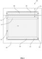
- FIG. 2 schematically illustrates an end wall 120 of one of the farming cells 108.
- the illustrated end wall 120 is an outer wall 200 of the farming cell 108 such that one side of the outer wall 200 is exposed to the interior of the farming cell 108 and the other side of the outer wall 200 is exposed to the open body of water in which the farming system 100 is disposed.
- the outer wall 200 is partially formed from the structural frame 106 which includes an outer wall frame 202 that surrounds an outer surface 218.
- the outer surface 218 is substantially covered or closed by a barrier 220 which inhibits the unwanted escape of product from the farming cell 108 into the open water.
- substantially means that the barrier 220 is sized to eliminate gaps that are large enough for the escape of the product being farmed. For large fish, relatively large gaps may be present between the outer wall frame 202 and the barrier 220 while still deeming the outer surface 218 covered or closed.
- the barrier 220 includes a first roller 204, a second roller 206, a continuous net 212, and a scrubber 214.
- the continuous net 212 is formed in a manner that allows for the passage of water, small creatures, and other nutrients or food sources but that inhibits the passage of the product being farmed within the farming cell 108.
- the continuous net 212 can be formed using any suitable material including nylon, metal, rope, cable, and other materials or combinations thereof.
- the continuous net 212 is arranged in an oval shape including a first net wall 304, a second net wall 306, a first semi-circular surface 308, and a second semi-circular surface 310 best illustrated in FIG. 3 , with FIG. 2 illustrating only the first net wall 304.
- the first roller 204 is an elongated cylindrical roller supported by the outer wall frame 202 for rotation about a first axis 208.
- the first axis 208 is substantially parallel to the waterline 110 and is positioned above the waterline 110 to position some or all the first roller 204 above the waterline 110.
- the diameter and length of the first roller 204 are selected to provide the desired space between the two planar surfaces of the continuous net 212 and to assure the desired support for the continuous net 212 across the width of the outer surface 218.
- the construction of the continuous net 212 may be such that a minimum or maximum diameter is needed to assure that the continuous net 212 forms the first semi-circular surface 308 and engages the first roller 204.
- the first roller 204 may be formed from a single material (e.g., aluminum, steel, etc.) or may be formed from multiple materials.
- one construction includes a metallic core, that is coated or sealed to inhibit contact with the environment and then is covered with a more resilient or high-friction outer layer that facilitates engagement with the continuous net 212 and assures smooth movement while minimizing slippage and wear of the continuous net 212 or the first roller 204.
- the second roller 206 is an elongated cylindrical roller similar to the first roller 204 and supported by the outer wall frame 202 for rotation about a second axis 210.
- the second axis 210 is substantially parallel to the first axis 208 and is positioned at the opposite end of the outer surface 218 when compared to the first axis 208. Positioning the first axis 208 adjacent one end of the outer surface 218 and the second axis 210 adjacent the second end of the outer surface 218 assures that the desired coverage of the outer surface 218 is achieved.
- the continuous net 212 extends around the second roller 206 to form the second semi-circular surface 310.
- the size and materials used for the second roller 206 are selected to achieve the desired support of the continuous net 212 and to provide the desired level of engagement between the second roller 206 and the continuous net 212.
- first roller 204 and the second roller 206 are movable along a tension axis 216.
- first roller 204 and/or the second roller 206 are moved away from one another along the tension axis 216.
- the opposite movement produces a reduction in the tension level.
- the first roller 204 is the only roller that moves along the tension axis 216. The position of the first roller 204 above the waterline 110 makes installation, inspection, and maintenance of the moving mechanism easier.
- the scrubber 214 is positioned between the first roller 204 and the second roller 206. In most arrangements, the scrubber 214 is positioned fully below the waterline 110. However, other arrangements may position the scrubber 214 above or at the waterline 110 as may be desired.
- FIG. 3 is a side view of the outer wall 200 illustrated in FIG. 2 .
- the first roller 204 includes a motor 302 arranged to rotate the first roller 204.
- the first roller 204 includes a hollow portion and the motor 302 is disposed within that hollow portion.
- the motor 302 is disposed outside of the first roller 204 and either directly drives the first roller 204 or drives the first roller 204 indirectly (e.g., belt drive, gear drive, etc.).
- the motor 302 is connected to a computer or controller 320 that may receive operating information from the motor 302 and that sends control signals to the motor 302.
- the motor 302 may be any type of motor desired including but not limited to a variable speed motor where the controller 320 operates as a variable speed drive or controls a separate variable speed drive for the motor 302.
- the second roller 206 includes a sensor 312 that is operable to measure a tension in the continuous net 212.
- the sensor 312 could include a load cell or cells that measure the forces on the second roller 206 to determine the tension level of the continuous net 212.
- the sensor 312 sends signals indicative of the measured values to the controller 320.
- the controller 320 operates to analyze the measured values from the sensor 312 and calculate a tension level for the continuous net 212. This value can also be displayed by the controller 320 if desired.
- the controller 320 is operable to move one or both of the first roller 204 and the second roller 206 along the tension axis 216 to adjust the tension level to assure that the tension level remains within the desired tension range.
- While the illustrated construction shows the sensor 312 connected to the second roller 206, other constructions may couple the sensor 312 to the first roller 204 or to both rollers as may be desired. In addition, other sensors or methods of determining the tension level of the continuous net 212 may be suitable for use.
- a net integrity sensor 318 in the form of a camera or imaging device is positioned near the first roller 204 to allow for the viewing of the continuous net 212 as the continuous net 212 passes over the first roller 204.
- the net integrity sensor 318 is coupled to the controller 320 or other system that interprets the images to determine the integrity of the continuous net 212.
- the controller 320 includes an AI-based computer program that is able to analyze the integrity of the continuous net 212 and trigger an alarm 322 if damage to the continuous net 212 is detected.
- the alarm 322 could include an audible alarm 322, a visual alarm 322, or any other suitable alarm 322 or communication that may be desired.
- the scrubber 214 includes an outer member 314 and an inner member 316 that are illustrated in a non-scrubbing position in FIG. 3 .
- the non-scrubbing position one or both of the outer member 314 and the inner member 316 are spaced apart from the second net wall 306.
- the outer member 314 is positioned outside of the continuous net 212 and specifically, outside of the second net wall 306.
- the inner member 316 is disposed between the first net wall 304 and the second net wall 306.
- FIG. 4 illustrates the same components illustrated in FIG. 3 but with the scrubber 214 in a scrubbing position.
- the inner member 316 is a roller that rolls on the second net wall 306 as the second net wall 306 moves past the scrubber 214.
- the inner member 316' functions simply as backing or a support surface for the second net wall 306 to resist movement that results from contact between the outer member 314 and the second net wall 306.
- the outer member 314 engages the second net wall 306 and scrubs or removes debris from the second net wall 306.
- the inner member 316 is a scrubbing member rather than a roller. In these arrangements, the inner member 316 is similar in construction to the outer member 314 and both the outer member 314 and the inner member 316 perform a cleaning operation.
- the surface of the outer member 314 includes a material suitable for cleaning the particular material used to form the continuous net 212.
- the outer member 314 may include a resilient material such as rubber, wire mesh, and the like which is suitable for cleaning the continuous net 212 without causing damage or wear.
- the inner member 316 if in the form of a roller may be made of similar materials as the first roller 204. If the inner member 316 also performs a cleaning operation, it would be made of materials similar to those used for the outer member 314.
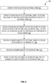
- FIG. 5 illustrates the assembly and operation of the outer wall 200 illustrated in Figs. 2-4 .
- the first roller 204 is connected to an outer wall frame 202 (block 502).
- the second roller 206 is connected to the outer wall frame 202 with the second roller 206 and the first roller 204 positioned on opposite sides of the outer wall frame 202 (block 504).
- the continuous net 212 is positioned around the first roller 204 and the second roller 206 to define the first net wall 304 and the second net wall 306, the first roller 204, the second roller 206, and the continuous net 212 cooperating to define a barrier 220 (block 506).
- the barrier 220 is positioned adjacent the outer wall frame 202 to close an outer surface 218 of the farming cell 108 (block 508).
- a scrubber 214 is positioned adjacent the second net wall (block 510) and the first roller 204 is rotated to move the second net wall 306 past the scrubber 214 to clean the surface of the second net wall (block 512).
- the controller 320 includes a micro-processer or other computer controller that can receive inputs including signals from each of the motors 302 and/or sensors 312 as well as other motors or sensors and produce outputs such as control signals that control the operation of the motor 302, the scrubber 214, and the tensioning mechanism that operates to maintain the tension of the continuous net 212.
- Suitable controllers 320 include large scale controllers such as SCADA systems, computer controllers, PC-based controllers, programable logic controllers (PLC), and the like. While the controller 320 is described as a single component, multiple devices could be employed together to perform the functions of the controller 320. Thus, the controller 320 encompasses all of the devices used to perform the various functions attributed to the controller 320 or a computer. In addition, non-computer-based controllers could be employed as desired.
- the farming system 100 illustrated and described herein is specifically applicable to large scale offshore aquaculture farms with the farming system 100 designed to be much more robust and able to cope with the large wave heights and high winds seen during a typical North Atlantic winter.
- the barrier 220 is coupled to the outer wall frame 202 to cover the outer surface 218.
- the continuous net 212 is arranged around the first roller 204 and the second roller 206 to define the first net wall 304, second net wall 306, first semi-circular surface 308, and the second semi-circular surface 310.
- the sensor 312 measures the tension level of the continuous net 212 and sends that information to the controller 320.
- the controller 320 determines if the measured tension level falls within a desired operating range and adjusts the tension level if it does not fall within the desired range. As described, the tension is increased by moving the first roller 204 and the second roller 206 away from one another and it is reduced by moving the first roller 204 and the second roller 206 toward one another. In one construction, only the first roller 204 is moved.
- the motor 302 is operated either continuously or periodically to rotate the first roller 204 and to move the continuous net 212 around the first roller 204 and the second roller 206. A portion of the continuous net 212 passes over the first roller 204 and moves through the field of view of the net integrity sensor 318.
- the net integrity sensor 318 captures images of the continuous net 212 or other data and transmits that data to the controller 320 for analysis.
- a program such as an AI program analyzes the images and determines if any unacceptable damage exists. If unacceptable damage is detected, the controller 320 can trigger the alarm 322 and perform any additional steps or communication desired.
- the scrubber 214 can move between the non-scrubbing position illustrated in FIG. 3 and the scrubbing position illustrated in FIG. 4 .
- the outer member 314 and the inner member 316 move toward one another and contact the second net wall 306.
- the inner member 316 acts as a support to allow the outer member 314 to apply a desired level of force to the second net wall 306 to achieve the desired level of cleaning. Any debris that is removed falls or floats into the open body of water as the outer member 314 is positioned outside of the farming cell 108.
- the inner member 316 performs a scrubbing operation rather than just a support function.
- the net integrity sensor 318 may also be employed to analyze the continuous net 212 after or during a scrubbing operation to verify that the cleaning of the continuous net 212 is sufficient. In some constructions, the net integrity sensor 318 triggers a scrubbing operation in response to detecting significant debris in the continuous net 212.
- barrier 220 advantageously provides a double wall to prevent the escape of the product being farmed.
- the ability to move the continuous net 212 to allow continuous or periodic above the waterline inspections of the net integrity greatly reduces the cost of the inspections as well as the potential time that a defect may go undetected.
- the ability to scrub or clean the net without the use of divers or remote operated vehicles reduces the cost and difficulty associated with cleaning the nets.
Landscapes
- Life Sciences & Earth Sciences (AREA)
- Environmental Sciences (AREA)
- Marine Sciences & Fisheries (AREA)
- Animal Husbandry (AREA)
- Biodiversity & Conservation Biology (AREA)
- Zoology (AREA)
- Farming Of Fish And Shellfish (AREA)
Abstract
Description
- Aquaculture is a growing business in which fish or other products are grown in a large body of water such as an ocean or lake. Many of these aquaculture systems are positioned in deep-sea areas such as the North Sea or the Atlantic Ocean where weather, tides, and animals can be a concern. Fish or other product can escape from aquaculture farms due to damage caused by weather or these other sources. As an example, approximately seventy-five percent of all fish escapes from fish farms are related to holes or tears in the containment nets. Increasing the integrity of these subsurface nets has always been a challenge.
- Fish escapes may lead to high financial losses and a potential mixing of farmed fish or product with the natural wild stocks. This mixing can introduce disease and genetic problems to the natural wild stocks. It is expected that future aquaculture will include larger farms and may be positioned further out to sea, with these fish farms holding more product and being exposed to harsher conditions, product escape events will only grow and be scrutinized more closely.
- Many systems employ manual inspection either by a diver or a remote operated vehicle (ROV) and camera along with manual net cleaning operations. This type of inspection for holes or tears in nets does not provide for constant monitoring and allows for a hole, damage, or debris in the net to be undiscovered for a period of time.
- In one aspect, a farming system for use in water-based farming of a product includes a structural frame arranged to define a farming cell having an outer wall frame that defines an outer surface. A barrier is coupled to the outer wall frame to define an outer wall. The barrier includes a first roller coupled to the outer wall frame for rotation about a first axis, the first roller positioned adjacent to a first edge of the outer wall frame. A second roller is coupled to the outer wall frame for rotation about a second axis that is parallel to the first axis, the second roller positioned adjacent to a second edge of the outer wall frame, the second edge opposite the first edge. A continuous net is positioned around the first roller and the second roller to define a first net wall and a second net wall that each cover the outer surface to close the outer wall. The farming system also includes a scrubber coupled to the second net wall and a drive system operable to rotate the first roller about the first axis to produce movement of the second net wall with respect to the scrubber.
- The farming system may also position the first roller completely above a waterline and the first axis parallel to the waterline.
- The farming system may also include a net integrity sensor positioned to detect a condition of the continuous net when the continuous net passes above the waterline.
- The farming system may also include a net integrity sensor that includes a camera and a controller that is operable to autonomously detect a damaged portion of the continuous net and in response to the detection of the damaged portion activate an alarm.
- The farming system may also separate the first roller and the second roller by a first distance, and one of the first roller and the second roller is movable in a direction normal to the first axis to vary the first distance.
- The farming system may also include a sensor coupled to the continuous net and operable to measure a tension level of the continuous net, and where the first distance is varied in response to the measured tension level. Other technical features may be readily apparent to one skilled in the art from the following figures, descriptions, and claims.
- The farming system may employ a scrubber that includes an inner member disposed between the first net wall and the second net wall and an outer member disposed outside of the second net wall.
- The farming system may also include an outer member that includes a resilient portion arranged to engage and scrub the second net wall as the second net wall moves with respect to the outer member.
- The farming system may also include a drive system that includes a motor disposed within the first roller.
- In one aspect, a method of enclosing a farming cell for use in water-based farming of a product, the method includes connecting a first roller to an outer wall frame, connecting a second roller to the outer wall frame, the second roller and the first roller positioned on opposite sides of the outer wall frame, extending a continuous net around the first roller and the second roller to define a first net wall and a second net wall, the first roller, the second roller, and the continuous net cooperating to define a barrier, positioning the barrier adjacent the outer wall frame to close an outer surface of the farming cell, positioning a scrubber adjacent the second net wall, rotating the first roller to move the second net wall past the scrubber to clean the surface of the second net wall.
- The method of enclosing a farming cell may also position the first roller completely above a waterline and the first axis parallel to the waterline.
- The method of enclosing a farming cell may also include detecting a condition of the continuous net when the continuous net passes above the waterline using a net integrity sensor.
- The method of enclosing a farming cell may also include a net integrity sensor that includes a camera and a controller, and where the detecting step includes autonomously detecting a damaged portion of the continuous net and activating an alarm in response to the detection of the damaged portion.
- The method of enclosing a farming cell may also include moving one of the first roller and the second roller along a direction that is normal to the first axis to vary a first distance between the first roller and the second roller.
- The method of enclosing a farming cell may also include measuring a tension level of the continuous net using a sensor coupled to the continuous net and varying the first distance in response to the tension level.
- The method of enclosing a farming cell may also include a scrubber that includes an inner member disposed between the first net wall and the second net wall and an outer member disposed outside of the second net wall.
- The method of enclosing a farming cell may also include moving one of the inner member and the outer member between a non-scrubbing position in which the inner member and the outer member are spaced apart from the second net wall and a scrubbing position in which the inner member and the outer member are in contact with the second net wall.
- The method of enclosing a farming cell may also include an outer member that includes a resilient portion arranged to engage and scrub the second net wall as the second net wall moves with respect to the outer member.
- The method of enclosing a farming cell may also include operating a motor disposed within the first roller to rotate the first roller about the first axis.
- It is understood that the system according to the first aspect, in embodiments, is implemented to carry out the steps of the method according to the second aspect.
- Other technical features may be readily apparent to one skilled in the art from the following figures, descriptions, and claims.
- To easily identify the discussion of any particular element or act, the most significant digit or digits in a reference number refer to the figure number in which that element is first introduced.
-
FIG. 1 is a perspective view of an aquaculture farming system including a plurality of farming cells. -
FIG. 2 is a schematic illustration of an end wall or outer wall of a farming cell of the farming system ofFIG. 1 including a barrier. -
FIG. 3 is a schematic side view of the outer wall and barrier ofFIG. 2 including a scrubber in a non-scrubbing position. -
FIG. 4 is a schematic side view of the outer wall and barrier ofFIG. 2 including the scrubber in a scrubbing position. -
FIG. 5 is a flow chart illustrating one arrangement of the barrier ofFIG. 2 . - Before any embodiments of the invention are explained in detail, it is to be understood that the invention is not limited in its application to the details of construction and the arrangement of components set forth in this description or illustrated in the following drawings. The invention is capable of other embodiments and of being practiced or of being carried out in various ways. Also, it is to be understood that the phraseology and terminology used herein is for the purpose of description and should not be regarded as limiting. Furthermore, while multiple embodiments or constructions may be described herein, any features, methods, steps, components, and the like described with regard to one embodiment are equally applicable to other embodiments absent a specific statement to the contrary.
- Various technologies that pertain to systems and methods will now be described with reference to the drawings, where like reference numerals represent like elements throughout. The drawings discussed below, and the various embodiments used to describe the principles of the present disclosure in this patent document are by way of illustration only and should not be construed in any way to limit the scope of the disclosure. Those skilled in the art will understand that the principles of the present disclosure may be implemented in any suitably arranged apparatus. It is to be understood that functionality that is described as being carried out by certain system elements may be performed by multiple elements. Similarly, for instance, an element may be configured to perform functionality that is described as being carried out by multiple elements. The numerous innovative teachings of the present application will be described with reference to exemplary non-limiting embodiments.
- While terms such as "first", "second", "third" and so forth may be used herein to refer to various elements, information, functions, or acts, these elements, information, functions, or acts should not be limited by these terms. Rather these numeral adjectives are used to distinguish different elements, information, functions or acts from each other. For example, a first element, information, function, or act could be termed a second element, information, function, or act, and, similarly, a second element, information, function, or act could be termed a first element, information, function, or act, without departing from the scope of the present disclosure.
- In addition, the term "adjacent to" may mean that an element is relatively near to but not in contact with a further element or that the element is in contact with the further portion, unless the context clearly indicates otherwise. Further, the phrase "based on" is intended to mean "based, at least in part, on" unless explicitly stated otherwise. Terms "about" or "substantially" or like terms are intended to cover variations in a value that are within normal industry manufacturing tolerances for that dimension. If no industry standard is available, a variation of twenty percent would fall within the meaning of these terms unless otherwise stated.
-
FIG. 1 illustrates afarming system 100 suitable for use to raise or farm products in a body ofwater 102 such as an ocean or lake. Thefarming system 100 ofFIG. 1 is particularly suited to raising fish in a large body of water such as the North Sea or the Atlantic Ocean. Of course, other products such as shellfish, or plant-based products could also be farmed in thefarming system 100 ofFIG. 1 . In addition, while thefarming system 100 is well-suited for the particular environment offshore, it could also be employed in smaller bodies of water or near the shore (e.g., in a bay or other confined body). - The
farming system 100 includes acentral hub 104 and astructural frame 106 that are arranged to define a plurality offarming cells 108. Thecentral hub 104 is a cylindrical member having a central axis that extends vertically. Thecentral hub 104 is arranged such that a portion extends above awaterline 110. In the illustrated construction, acontrol room 112 or other space is positioned on top of thecentral hub 104 to provide space for workers, operators, and the like. - The
structural frame 106 is formed from various structural members that are arranged to define a perimeter for each of thefarming cells 108. In the illustrated construction, thestructural frame 106 includes a plurality ofupper spokes 114 and a plurality oflower spokes 116 with each upper spoke 114 and lower spoke 116 extending radially outward from thecentral hub 104. Theupper spokes 114 andlower spokes 116 cooperate with the remainder of thestructural frame 106 to define eight substantiallyidentical farming cells 108. Each of thefarming cells 108 is wedge-shaped with a narrow end near thecentral hub 104 and a wide end at the radially outermost portion of thefarming cell 108. This arrangement produces tworectangular side walls 118, arectangular end wall 120, a trapezoidal or wedge-shapedtop wall 122 and a similarly shapedbottom wall 124 for each of thefarming cells 108. Thecentral hub 104 forms anarrow end wall 120 for eachfarming cell 108 near the narrow end. Of course, other arrangements of thefarming system 100 and/or each of thefarming cells 108 could be employed. For example, cubic farming cells could be employed or more or fewer farming cells could be formed as desired. - In the illustrated construction, one or more of the
farming cells 108 may be provided with amovable wall 126. Themovable wall 126 can be positioned at some intermediate position within thefarming cell 108 to divide thefarming cell 108. In addition, themovable wall 126 could be movable to herd the product into a particular space or location for removal, harvesting, or other purposes. - The
central hub 104,structural frame 106, and any other components that form thefarming system 100 are selected to provide sufficient buoyancy to assure that a portion of thefarming system 100 remains above thewaterline 110 at all times. Thefarming system 100 may be anchored or moored in a desired position or may include a drive and steering system that allows an operator to maintain thefarming system 100 in a desired position or to move thefarming system 100 as may be required. - As illustrated in
FIG. 1 , thestructural frame 106 is arranged to define the perimeter of various walls that cooperate to define eachfarming cell 108. However, in order to farm product, and in particular fish, each of the walls, with the possible exception of thetop wall 122 must be substantially enclosed to adequately contain the product being farmed. The term substantially enclosed means that the walls may include openings that are small enough to inhibit the unwanted escape of the product while also allowing for the passage of water, nutrients, and small items. -
FIG. 2 schematically illustrates anend wall 120 of one of thefarming cells 108. Theillustrated end wall 120 is anouter wall 200 of thefarming cell 108 such that one side of theouter wall 200 is exposed to the interior of thefarming cell 108 and the other side of theouter wall 200 is exposed to the open body of water in which thefarming system 100 is disposed. - The
outer wall 200 is partially formed from thestructural frame 106 which includes anouter wall frame 202 that surrounds anouter surface 218. Theouter surface 218 is substantially covered or closed by abarrier 220 which inhibits the unwanted escape of product from thefarming cell 108 into the open water. As used here, "substantially" means that thebarrier 220 is sized to eliminate gaps that are large enough for the escape of the product being farmed. For large fish, relatively large gaps may be present between theouter wall frame 202 and thebarrier 220 while still deeming theouter surface 218 covered or closed. - The
barrier 220 includes afirst roller 204, asecond roller 206, acontinuous net 212, and ascrubber 214. Thecontinuous net 212 is formed in a manner that allows for the passage of water, small creatures, and other nutrients or food sources but that inhibits the passage of the product being farmed within thefarming cell 108. Thecontinuous net 212 can be formed using any suitable material including nylon, metal, rope, cable, and other materials or combinations thereof. Thecontinuous net 212 is arranged in an oval shape including a firstnet wall 304, a secondnet wall 306, a firstsemi-circular surface 308, and a secondsemi-circular surface 310 best illustrated inFIG. 3 , withFIG. 2 illustrating only the firstnet wall 304. - The
first roller 204 is an elongated cylindrical roller supported by theouter wall frame 202 for rotation about afirst axis 208. In the illustrated construction, thefirst axis 208 is substantially parallel to thewaterline 110 and is positioned above thewaterline 110 to position some or all thefirst roller 204 above thewaterline 110. The diameter and length of thefirst roller 204 are selected to provide the desired space between the two planar surfaces of thecontinuous net 212 and to assure the desired support for thecontinuous net 212 across the width of theouter surface 218. The construction of thecontinuous net 212 may be such that a minimum or maximum diameter is needed to assure that the continuous net 212 forms the firstsemi-circular surface 308 and engages thefirst roller 204. - The
first roller 204 may be formed from a single material (e.g., aluminum, steel, etc.) or may be formed from multiple materials. For example, one construction includes a metallic core, that is coated or sealed to inhibit contact with the environment and then is covered with a more resilient or high-friction outer layer that facilitates engagement with thecontinuous net 212 and assures smooth movement while minimizing slippage and wear of thecontinuous net 212 or thefirst roller 204. - The
second roller 206 is an elongated cylindrical roller similar to thefirst roller 204 and supported by theouter wall frame 202 for rotation about asecond axis 210. In the illustrated construction, thesecond axis 210 is substantially parallel to thefirst axis 208 and is positioned at the opposite end of theouter surface 218 when compared to thefirst axis 208. Positioning thefirst axis 208 adjacent one end of theouter surface 218 and thesecond axis 210 adjacent the second end of theouter surface 218 assures that the desired coverage of theouter surface 218 is achieved. - The
continuous net 212 extends around thesecond roller 206 to form the secondsemi-circular surface 310. As with thefirst roller 204, the size and materials used for thesecond roller 206 are selected to achieve the desired support of thecontinuous net 212 and to provide the desired level of engagement between thesecond roller 206 and thecontinuous net 212. - In order to maintain a desired tension level one or both of the
first roller 204 and thesecond roller 206 are movable along atension axis 216. Thus, in order to increase the tension applied to thecontinuous net 212, thefirst roller 204 and/or thesecond roller 206 are moved away from one another along thetension axis 216. The opposite movement produces a reduction in the tension level. In preferred constructions, thefirst roller 204 is the only roller that moves along thetension axis 216. The position of thefirst roller 204 above thewaterline 110 makes installation, inspection, and maintenance of the moving mechanism easier. - The
scrubber 214, better illustrated inFIG. 3 and FIG. 4 is positioned between thefirst roller 204 and thesecond roller 206. In most arrangements, thescrubber 214 is positioned fully below thewaterline 110. However, other arrangements may position thescrubber 214 above or at thewaterline 110 as may be desired. -
FIG. 3 is a side view of theouter wall 200 illustrated inFIG. 2 . As is better illustrated inFIG. 2 , thefirst roller 204 includes amotor 302 arranged to rotate thefirst roller 204. In the illustrated construction, thefirst roller 204 includes a hollow portion and themotor 302 is disposed within that hollow portion. In other constructions, themotor 302 is disposed outside of thefirst roller 204 and either directly drives thefirst roller 204 or drives thefirst roller 204 indirectly (e.g., belt drive, gear drive, etc.). - The
motor 302 is connected to a computer orcontroller 320 that may receive operating information from themotor 302 and that sends control signals to themotor 302. Themotor 302 may be any type of motor desired including but not limited to a variable speed motor where thecontroller 320 operates as a variable speed drive or controls a separate variable speed drive for themotor 302. - The
second roller 206 includes asensor 312 that is operable to measure a tension in thecontinuous net 212. Thesensor 312 could include a load cell or cells that measure the forces on thesecond roller 206 to determine the tension level of thecontinuous net 212. Thesensor 312 sends signals indicative of the measured values to thecontroller 320. Thecontroller 320 operates to analyze the measured values from thesensor 312 and calculate a tension level for thecontinuous net 212. This value can also be displayed by thecontroller 320 if desired. In addition, thecontroller 320 is operable to move one or both of thefirst roller 204 and thesecond roller 206 along thetension axis 216 to adjust the tension level to assure that the tension level remains within the desired tension range. While the illustrated construction shows thesensor 312 connected to thesecond roller 206, other constructions may couple thesensor 312 to thefirst roller 204 or to both rollers as may be desired. In addition, other sensors or methods of determining the tension level of thecontinuous net 212 may be suitable for use. - A
net integrity sensor 318, in the form of a camera or imaging device is positioned near thefirst roller 204 to allow for the viewing of thecontinuous net 212 as the continuous net 212 passes over thefirst roller 204. Thenet integrity sensor 318 is coupled to thecontroller 320 or other system that interprets the images to determine the integrity of thecontinuous net 212. - In one construction, the
controller 320 includes an AI-based computer program that is able to analyze the integrity of thecontinuous net 212 and trigger analarm 322 if damage to thecontinuous net 212 is detected. Thealarm 322 could include anaudible alarm 322, avisual alarm 322, or any othersuitable alarm 322 or communication that may be desired. - The
scrubber 214 includes anouter member 314 and aninner member 316 that are illustrated in a non-scrubbing position inFIG. 3 . In the non-scrubbing position, one or both of theouter member 314 and theinner member 316 are spaced apart from the secondnet wall 306. Theouter member 314 is positioned outside of thecontinuous net 212 and specifically, outside of the secondnet wall 306. Theinner member 316 is disposed between the firstnet wall 304 and the secondnet wall 306. -
FIG. 4 illustrates the same components illustrated inFIG. 3 but with thescrubber 214 in a scrubbing position. In the scrubbing position, one or both of theouter member 314 and theinner member 316 move toward one another and into contact with the secondnet wall 306. In one arrangement, theinner member 316 is a roller that rolls on the secondnet wall 306 as the secondnet wall 306 moves past thescrubber 214. In this arrangement, the inner member 316' functions simply as backing or a support surface for the secondnet wall 306 to resist movement that results from contact between theouter member 314 and the secondnet wall 306. Theouter member 314 engages the secondnet wall 306 and scrubs or removes debris from the secondnet wall 306. With this arrangement, only the outer surface of the secondnet wall 306 is scrubbed which assures that any removed debris drops harmlessly outside of thefarming cell 108. In other constructions, theinner member 316 is a scrubbing member rather than a roller. In these arrangements, theinner member 316 is similar in construction to theouter member 314 and both theouter member 314 and theinner member 316 perform a cleaning operation. - To facilitate the cleaning, the surface of the
outer member 314 includes a material suitable for cleaning the particular material used to form thecontinuous net 212. In one construction, theouter member 314 may include a resilient material such as rubber, wire mesh, and the like which is suitable for cleaning thecontinuous net 212 without causing damage or wear. Theinner member 316, if in the form of a roller may be made of similar materials as thefirst roller 204. If theinner member 316 also performs a cleaning operation, it would be made of materials similar to those used for theouter member 314. -
FIG. 5 illustrates the assembly and operation of theouter wall 200 illustrated inFigs. 2-4 . In a first step, thefirst roller 204 is connected to an outer wall frame 202 (block 502). Similarly, thesecond roller 206 is connected to theouter wall frame 202 with thesecond roller 206 and thefirst roller 204 positioned on opposite sides of the outer wall frame 202 (block 504). Thecontinuous net 212 is positioned around thefirst roller 204 and thesecond roller 206 to define the firstnet wall 304 and the secondnet wall 306, thefirst roller 204, thesecond roller 206, and thecontinuous net 212 cooperating to define a barrier 220 (block 506). Thebarrier 220 is positioned adjacent theouter wall frame 202 to close anouter surface 218 of the farming cell 108 (block 508). Ascrubber 214 is positioned adjacent the second net wall (block 510) and thefirst roller 204 is rotated to move the secondnet wall 306 past thescrubber 214 to clean the surface of the second net wall (block 512). - The
controller 320 includes a micro-processer or other computer controller that can receive inputs including signals from each of themotors 302 and/orsensors 312 as well as other motors or sensors and produce outputs such as control signals that control the operation of themotor 302, thescrubber 214, and the tensioning mechanism that operates to maintain the tension of thecontinuous net 212.Suitable controllers 320 include large scale controllers such as SCADA systems, computer controllers, PC-based controllers, programable logic controllers (PLC), and the like. While thecontroller 320 is described as a single component, multiple devices could be employed together to perform the functions of thecontroller 320. Thus, thecontroller 320 encompasses all of the devices used to perform the various functions attributed to thecontroller 320 or a computer. In addition, non-computer-based controllers could be employed as desired. - The
farming system 100 illustrated and described herein is specifically applicable to large scale offshore aquaculture farms with thefarming system 100 designed to be much more robust and able to cope with the large wave heights and high winds seen during a typical North Atlantic winter. - In operation, the
barrier 220 is coupled to theouter wall frame 202 to cover theouter surface 218. Thecontinuous net 212 is arranged around thefirst roller 204 and thesecond roller 206 to define the firstnet wall 304, secondnet wall 306, firstsemi-circular surface 308, and the secondsemi-circular surface 310. Thesensor 312 measures the tension level of thecontinuous net 212 and sends that information to thecontroller 320. Thecontroller 320 determines if the measured tension level falls within a desired operating range and adjusts the tension level if it does not fall within the desired range. As described, the tension is increased by moving thefirst roller 204 and thesecond roller 206 away from one another and it is reduced by moving thefirst roller 204 and thesecond roller 206 toward one another. In one construction, only thefirst roller 204 is moved. - The
motor 302 is operated either continuously or periodically to rotate thefirst roller 204 and to move thecontinuous net 212 around thefirst roller 204 and thesecond roller 206. A portion of the continuous net 212 passes over thefirst roller 204 and moves through the field of view of thenet integrity sensor 318. Thenet integrity sensor 318 captures images of thecontinuous net 212 or other data and transmits that data to thecontroller 320 for analysis. A program, such as an AI program analyzes the images and determines if any unacceptable damage exists. If unacceptable damage is detected, thecontroller 320 can trigger thealarm 322 and perform any additional steps or communication desired. - As the
continuous net 212 moves, thescrubber 214 can move between the non-scrubbing position illustrated inFIG. 3 and the scrubbing position illustrated inFIG. 4 . To move to the scrubbing position, one or both of theouter member 314 and theinner member 316 move toward one another and contact the secondnet wall 306. In preferred constructions, only one of theouter member 314 and theinner member 316, and typically theouter member 314 moves to initiate the scrubbing operation. Theinner member 316 acts as a support to allow theouter member 314 to apply a desired level of force to the secondnet wall 306 to achieve the desired level of cleaning. Any debris that is removed falls or floats into the open body of water as theouter member 314 is positioned outside of thefarming cell 108. In some constructions, theinner member 316 performs a scrubbing operation rather than just a support function. - The
net integrity sensor 318 may also be employed to analyze thecontinuous net 212 after or during a scrubbing operation to verify that the cleaning of thecontinuous net 212 is sufficient. In some constructions, thenet integrity sensor 318 triggers a scrubbing operation in response to detecting significant debris in thecontinuous net 212. - It should also be noted that while the construction described herein includes a
scrubber 214 that is movable between a scrubbing position and a non-scrubbing position, other constructions may fix thescrubber 214 in a scrubbing position and move thecontinuous net 212 continuously or only when scrubbing is desired. - The use of the
barrier 220 described herein advantageously provides a double wall to prevent the escape of the product being farmed. In addition, the ability to move thecontinuous net 212 to allow continuous or periodic above the waterline inspections of the net integrity greatly reduces the cost of the inspections as well as the potential time that a defect may go undetected. Furthermore, the ability to scrub or clean the net without the use of divers or remote operated vehicles reduces the cost and difficulty associated with cleaning the nets. - Although an exemplary embodiment of the present disclosure has been described in detail, those skilled in the art will understand that various changes, substitutions, variations, and improvements disclosed herein may be made without departing from the spirit and scope of the disclosure in its broadest form.
- None of the description in the present application should be read as implying that any particular element, step, act, or function is an essential element, which must be included in the claim scope: the scope of patented subject matter is defined only by the allowed claims. Moreover, none of these claims are intended to invoke a means plus function claim construction unless the exact words "means for" are followed by a participle.
- Features, advantages or alternative embodiments herein can be assigned to the other claimed objects and vice versa. In other words, claims for the providing systems can be improved with features described or claimed in the context of the methods. In this case, the functional features of the method are embodied by objective units of the providing system (and vice versa).
Claims (15)
- A farming system for use in water-based farming of a product, the farming system comprising:a structural frame arranged to define a farming cell having an outer wall frame that defines an outer surface;a barrier coupled to the outer wall frame to define an outer wall, the barrier including:a first roller coupled to the outer wall frame for rotation about a first axis, the first roller positioned adjacent to a first edge of the outer wall frame; a second roller coupled to the outer wall frame for rotation about a second axis that is parallel to the first axis, the second roller positioned adjacent to a second edge of the outer wall frame, the second edge opposite the first edge; anda continuous net positioned around the first roller and the second roller, the continuous net defining a first net wall and a second net wall that each cover the outer surface to close the outer wall;a scrubber coupled to the second net wall; anda drive system operable to rotate the first roller about the first axis to produce movement of the second net wall with respect to the scrubber.
- The farming system of claim 1, wherein the first roller is positioned completely above a waterline and the first axis is parallel to the waterline.
- The farming system of claim 2, further comprising a net integrity sensor positioned to detect a condition of the continuous net when the continuous net passes above the waterline.
- The farming system of any of the claims 1-3, wherein the first roller and the second roller are separated by a first distance, and wherein one of the first roller and the second roller is movable in a direction normal to the first axis to vary the first distance.
- The farming system of claim 5, further comprising a sensor coupled to the continuous net and operable to measure a tension level of the continuous net, and wherein the first distance is varied in response to the measured tension level.
- The farming system of any of the claims 1-5, wherein the drive system includes a motor disposed within the first roller.
- A method of enclosing a farming cell for use in water-based farming of a product, the method comprising:connecting a first roller to an outer wall frame;connecting a second roller to the outer wall frame, the second roller and the first roller positioned on opposite sides of the outer wall frame;extending a continuous net around the first roller and the second roller to define a first net wall and a second net wall, the first roller, the second roller, and the continuous net cooperating to define a barrier;positioning the barrier adjacent the outer wall frame to close an outer surface of the farming cell;positioning a scrubber adjacent the second net wall;rotating the first roller to move the second net wall past the scrubber to clean the surface of the second net wall.
- The method of claim 7, wherein the first roller is positioned completely above a waterline and the first axis is parallel to the waterline.
- The method of claim 8, further comprising detecting a condition of the continuous net when the continuous net passes above the waterline using a net integrity sensor.
- The farming system of claim 3 or the method of claim 9, wherein the net integrity sensor includes a camera and a controller that is operable to autonomously detect a damaged portion of the continuous net and to activate an alarm in response to the detection of the damaged portion.
- The method of any of the claims 7 - 10, further comprising moving one of the first roller and the second roller along a direction that is normal to the first axis to vary a first distance between the first roller and the second roller.
- The method of claim 11, further comprising measuring a tension level of the continuous net using a sensor coupled to the continuous net, and varying the first distance in response to the tension level.
- The farming system of any of the claims 1-5 or the method of any of the claims 7-12, wherein the scrubber includes an inner member disposed between the first net wall and the second net wall and an outer member disposed outside of the second net wall.
- The farming system of claim 13 or the method of claim 13, wherein one of the inner member and the outer member is movable between a non-scrubbing position in which the inner member and the outer member are spaced apart from the second net wall and a scrubbing position in which the inner member and the outer member are in contact with the second net wall, or
wherein the outer member includes a resilient portion arranged to engage and scrub the second net wall as the second net wall moves with respect to the outer member. - The method of any of the claims 7-14, further comprising operating a motor disposed within the first roller to rotate the first roller about the first axis.
Applications Claiming Priority (1)
| Application Number | Priority Date | Filing Date | Title |
|---|---|---|---|
| GB2301914.4A GB2626978A (en) | 2023-02-10 | 2023-02-10 | Farming system for use in aquaculture |
Publications (2)
| Publication Number | Publication Date |
|---|---|
| EP4413855A1 true EP4413855A1 (en) | 2024-08-14 |
| EP4413855B1 EP4413855B1 (en) | 2026-04-01 |
Family
ID=85704358
Family Applications (1)
| Application Number | Title | Priority Date | Filing Date |
|---|---|---|---|
| EP24156241.2A Active EP4413855B1 (en) | 2023-02-10 | 2024-02-07 | Farming system for use in aquaculture |
Country Status (5)
| Country | Link |
|---|---|
| US (1) | US12302873B2 (en) |
| EP (1) | EP4413855B1 (en) |
| CN (1) | CN118476497A (en) |
| CA (1) | CA3228630A1 (en) |
| GB (1) | GB2626978A (en) |
Families Citing this family (1)
| Publication number | Priority date | Publication date | Assignee | Title |
|---|---|---|---|---|
| CN118749480B (en) * | 2024-09-03 | 2024-11-22 | 广东海洋大学 | A device for breaking nets and checking for leaks in deep-sea aquaculture cages |
Citations (4)
| Publication number | Priority date | Publication date | Assignee | Title |
|---|---|---|---|---|
| KR20110046998A (en) * | 2009-10-29 | 2011-05-06 | 전남대학교산학협력단 | Large net cage exchange device and net exchange method using the device |
| CN109663767A (en) * | 2019-01-25 | 2019-04-23 | 马立志 | Etting automatic flushing device and net cage |
| CN111053056A (en) * | 2020-01-19 | 2020-04-24 | 集美大学 | A chain screen changing device and method for aquaculture in a seawater pond circulating water cage |
| CN112273285A (en) * | 2020-11-03 | 2021-01-29 | 浙江海洋大学 | Double-layer aquaculture purse seine with cleaning device |
Family Cites Families (13)
| Publication number | Priority date | Publication date | Assignee | Title |
|---|---|---|---|---|
| US4495891A (en) * | 1979-07-13 | 1985-01-29 | Farm Fresh Shrimp Corporation | Method and apparatus for rearing aquatic animals |
| JPS63160165U (en) * | 1987-04-08 | 1988-10-19 | ||
| WO2006052146A1 (en) * | 2004-11-12 | 2006-05-18 | Ntnu Technology Transfer As | Marine structure for a fish cage for aquaculture with a net spanned by a tensegrity structure |
| NO322560B1 (en) * | 2004-11-12 | 2006-10-23 | Ntnu Technology Transfer As | Tensegrity structures for fish farming installations |
| CH710238A2 (en) * | 2014-10-14 | 2016-04-15 | Geobrugg Ag | Protective device for animal breeding, in particular fish, shellfish or mollusc farming. |
| JP7164550B2 (en) * | 2018-01-13 | 2022-11-01 | 株式会社新日本科学 | fish cage |
| NO345259B1 (en) | 2018-06-12 | 2020-11-23 | Kahrs Hansen As | Instrumentation system for integrity monitoring of a net barrier |
| CN209560693U (en) * | 2019-01-25 | 2019-10-29 | 马立志 | Etting breakage monitoring device and monitor and alarm system |
| CN110663588B (en) * | 2019-09-06 | 2022-03-01 | 湖北海洋工程装备研究院有限公司 | Fishing net rope connector, adjusting method and fishing net |
| CN110820389B (en) * | 2019-11-14 | 2021-12-14 | 舟山天沐水产科技有限公司 | Device for monitoring and early warning structural object damage according to stress |
| CN111698477A (en) * | 2020-06-18 | 2020-09-22 | 中国水产科学研究院东海水产研究所 | A breed environment and safety monitoring device for facility is bred to large-scale rail |
| CN113303260A (en) * | 2021-04-22 | 2021-08-27 | 舟山万达船舶设计有限公司 | Comprehensive marine culture facility |
| CN116076414A (en) * | 2022-08-31 | 2023-05-09 | 浙江海洋大学 | A kind of deep-sea anti-wind and wave culture net cage |
-
2023
- 2023-02-10 GB GB2301914.4A patent/GB2626978A/en active Pending
-
2024
- 2024-01-18 US US18/416,040 patent/US12302873B2/en active Active
- 2024-02-02 CN CN202410153400.XA patent/CN118476497A/en active Pending
- 2024-02-07 EP EP24156241.2A patent/EP4413855B1/en active Active
- 2024-02-08 CA CA3228630A patent/CA3228630A1/en active Pending
Patent Citations (4)
| Publication number | Priority date | Publication date | Assignee | Title |
|---|---|---|---|---|
| KR20110046998A (en) * | 2009-10-29 | 2011-05-06 | 전남대학교산학협력단 | Large net cage exchange device and net exchange method using the device |
| CN109663767A (en) * | 2019-01-25 | 2019-04-23 | 马立志 | Etting automatic flushing device and net cage |
| CN111053056A (en) * | 2020-01-19 | 2020-04-24 | 集美大学 | A chain screen changing device and method for aquaculture in a seawater pond circulating water cage |
| CN112273285A (en) * | 2020-11-03 | 2021-01-29 | 浙江海洋大学 | Double-layer aquaculture purse seine with cleaning device |
Also Published As
| Publication number | Publication date |
|---|---|
| US20240268359A1 (en) | 2024-08-15 |
| CN118476497A (en) | 2024-08-13 |
| GB202301914D0 (en) | 2023-03-29 |
| US12302873B2 (en) | 2025-05-20 |
| CA3228630A1 (en) | 2025-04-29 |
| EP4413855B1 (en) | 2026-04-01 |
| GB2626978A (en) | 2024-08-14 |
Similar Documents
| Publication | Publication Date | Title |
|---|---|---|
| US20240410858A1 (en) | Systems, methods and apparatus for in-service tank inspections | |
| US9739792B2 (en) | Device for pipe inspection and method of using same | |
| US12302873B2 (en) | Farming system for use in aquaculture | |
| US9061736B2 (en) | Hull robot for autonomously detecting cleanliness of a hull | |
| RU2375247C1 (en) | Method and device to reboard underwater equipment | |
| US20120046882A1 (en) | Method of detecting contamination of water using living organisms | |
| KR102648692B1 (en) | mooring type monitoring apparatus for marine environment | |
| US20240058655A1 (en) | Golf ball recovery systems, apparatus, and methods | |
| US11060256B2 (en) | Structural maintenance system | |
| EP3643594B1 (en) | Method and system for removing floating waste from water | |
| AU2017351740A1 (en) | Apparatus and method for the in-water removal and containment of biofouling from vessels | |
| CN119881251B (en) | A water quality monitoring instrument based on continuous monitoring technology | |
| US12302872B2 (en) | Farming system for use in aquaculture | |
| US12228524B2 (en) | Methods and systems to locate anomalies along an inside surface of a conveyance pipe | |
| Dunn et al. | LOCHNESS—a new multi-net midwater sampler | |
| KR20190112239A (en) | Stationary type jellyfish capturing apparatus | |
| CN120902881A (en) | Multi-parameter ocean observation buoy method and system with automatic lifting mechanism | |
| KR20250128510A (en) | aquaculture farms water quality management system | |
| JP7384731B2 (en) | Evaluation device, sluice system and evaluation method | |
| US20240166315A1 (en) | Monitoring the cleanliness of an underwater surface of a stationary object | |
| Fredriksson et al. | A field study to understand the currents and loads of a near shore finfish farm | |
| CN112761126A (en) | Underwater cleaning robot suitable for complex water area | |
| Skoglund et al. | Shallow water profiling platforms—SeaTramp and Octopus | |
| Kim | Mooring loads analysis of submersible aquaculture cage system using finite element method | |
| Rogers | Monitoring fatigue in offshore structures |
Legal Events
| Date | Code | Title | Description |
|---|---|---|---|
| PUAI | Public reference made under article 153(3) epc to a published international application that has entered the european phase |
Free format text: ORIGINAL CODE: 0009012 |
|
| STAA | Information on the status of an ep patent application or granted ep patent |
Free format text: STATUS: REQUEST FOR EXAMINATION WAS MADE |
|
| 17P | Request for examination filed |
Effective date: 20240207 |
|
| AK | Designated contracting states |
Kind code of ref document: A1 Designated state(s): AL AT BE BG CH CY CZ DE DK EE ES FI FR GB GR HR HU IE IS IT LI LT LU LV MC ME MK MT NL NO PL PT RO RS SE SI SK SM TR |
|
| STAA | Information on the status of an ep patent application or granted ep patent |
Free format text: STATUS: EXAMINATION IS IN PROGRESS |
|
| 17Q | First examination report despatched |
Effective date: 20250507 |
|
| GRAP | Despatch of communication of intention to grant a patent |
Free format text: ORIGINAL CODE: EPIDOSNIGR1 |
|
| STAA | Information on the status of an ep patent application or granted ep patent |
Free format text: STATUS: GRANT OF PATENT IS INTENDED |
|
| INTG | Intention to grant announced |
Effective date: 20250908 |
|
| GRAS | Grant fee paid |
Free format text: ORIGINAL CODE: EPIDOSNIGR3 |
|
| GRAA | (expected) grant |
Free format text: ORIGINAL CODE: 0009210 |
|
| STAA | Information on the status of an ep patent application or granted ep patent |
Free format text: STATUS: THE PATENT HAS BEEN GRANTED |
|
| AK | Designated contracting states |
Kind code of ref document: B1 Designated state(s): AL AT BE BG CH CY CZ DE DK EE ES FI FR GB GR HR HU IE IS IT LI LT LU LV MC ME MK MT NL NO PL PT RO RS SE SI SK SM TR |
|
| REG | Reference to a national code |
Ref country code: CH Ref legal event code: F10 Free format text: ST27 STATUS EVENT CODE: U-0-0-F10-F00 (AS PROVIDED BY THE NATIONAL OFFICE) Effective date: 20260401 Ref country code: GB Ref legal event code: FG4D |
|
| REG | Reference to a national code |
Ref country code: IE Ref legal event code: FG4D |
|
| REG | Reference to a national code |
Ref country code: DE Ref legal event code: R096 Ref document number: 602024003508 Country of ref document: DE |
|
| REG | Reference to a national code |
Ref country code: NL Ref legal event code: MP Effective date: 20260401 |