EP4412217A1 - Filtering method and apparatus, encoding method and apparatus, decoding method and apparatus, computer-readable medium, and electronic device - Google Patents
Filtering method and apparatus, encoding method and apparatus, decoding method and apparatus, computer-readable medium, and electronic device Download PDFInfo
- Publication number
- EP4412217A1 EP4412217A1 EP22874609.5A EP22874609A EP4412217A1 EP 4412217 A1 EP4412217 A1 EP 4412217A1 EP 22874609 A EP22874609 A EP 22874609A EP 4412217 A1 EP4412217 A1 EP 4412217A1
- Authority
- EP
- European Patent Office
- Prior art keywords
- quantization parameter
- image
- input
- deep learning
- block
- Prior art date
- Legal status (The legal status is an assumption and is not a legal conclusion. Google has not performed a legal analysis and makes no representation as to the accuracy of the status listed.)
- Pending
Links
Images





Classifications
-
- H—ELECTRICITY
- H04—ELECTRIC COMMUNICATION TECHNIQUE
- H04N—PICTORIAL COMMUNICATION, e.g. TELEVISION
- H04N19/00—Methods or arrangements for coding, decoding, compressing or decompressing digital video signals
- H04N19/10—Methods or arrangements for coding, decoding, compressing or decompressing digital video signals using adaptive coding
- H04N19/102—Methods or arrangements for coding, decoding, compressing or decompressing digital video signals using adaptive coding characterised by the element, parameter or selection affected or controlled by the adaptive coding
- H04N19/117—Filters, e.g. for pre-processing or post-processing
-
- G—PHYSICS
- G06—COMPUTING OR CALCULATING; COUNTING
- G06T—IMAGE DATA PROCESSING OR GENERATION, IN GENERAL
- G06T5/00—Image enhancement or restoration
- G06T5/60—Image enhancement or restoration using machine learning, e.g. neural networks
-
- H—ELECTRICITY
- H04—ELECTRIC COMMUNICATION TECHNIQUE
- H04N—PICTORIAL COMMUNICATION, e.g. TELEVISION
- H04N19/00—Methods or arrangements for coding, decoding, compressing or decompressing digital video signals
- H04N19/10—Methods or arrangements for coding, decoding, compressing or decompressing digital video signals using adaptive coding
- H04N19/102—Methods or arrangements for coding, decoding, compressing or decompressing digital video signals using adaptive coding characterised by the element, parameter or selection affected or controlled by the adaptive coding
- H04N19/124—Quantisation
-
- H—ELECTRICITY
- H04—ELECTRIC COMMUNICATION TECHNIQUE
- H04N—PICTORIAL COMMUNICATION, e.g. TELEVISION
- H04N19/00—Methods or arrangements for coding, decoding, compressing or decompressing digital video signals
- H04N19/80—Details of filtering operations specially adapted for video compression, e.g. for pixel interpolation
-
- H—ELECTRICITY
- H04—ELECTRIC COMMUNICATION TECHNIQUE
- H04N—PICTORIAL COMMUNICATION, e.g. TELEVISION
- H04N19/00—Methods or arrangements for coding, decoding, compressing or decompressing digital video signals
- H04N19/80—Details of filtering operations specially adapted for video compression, e.g. for pixel interpolation
- H04N19/82—Details of filtering operations specially adapted for video compression, e.g. for pixel interpolation involving filtering within a prediction loop
-
- H—ELECTRICITY
- H04—ELECTRIC COMMUNICATION TECHNIQUE
- H04N—PICTORIAL COMMUNICATION, e.g. TELEVISION
- H04N19/00—Methods or arrangements for coding, decoding, compressing or decompressing digital video signals
- H04N19/85—Methods or arrangements for coding, decoding, compressing or decompressing digital video signals using pre-processing or post-processing specially adapted for video compression
- H04N19/86—Methods or arrangements for coding, decoding, compressing or decompressing digital video signals using pre-processing or post-processing specially adapted for video compression involving reduction of coding artifacts, e.g. of blockiness
-
- G—PHYSICS
- G06—COMPUTING OR CALCULATING; COUNTING
- G06N—COMPUTING ARRANGEMENTS BASED ON SPECIFIC COMPUTATIONAL MODELS
- G06N3/00—Computing arrangements based on biological models
- G06N3/02—Neural networks
- G06N3/04—Architecture, e.g. interconnection topology
-
- G—PHYSICS
- G06—COMPUTING OR CALCULATING; COUNTING
- G06N—COMPUTING ARRANGEMENTS BASED ON SPECIFIC COMPUTATIONAL MODELS
- G06N3/00—Computing arrangements based on biological models
- G06N3/02—Neural networks
- G06N3/08—Learning methods
-
- G—PHYSICS
- G06—COMPUTING OR CALCULATING; COUNTING
- G06T—IMAGE DATA PROCESSING OR GENERATION, IN GENERAL
- G06T2207/00—Indexing scheme for image analysis or image enhancement
- G06T2207/20—Special algorithmic details
- G06T2207/20024—Filtering details
-
- H—ELECTRICITY
- H04—ELECTRIC COMMUNICATION TECHNIQUE
- H04N—PICTORIAL COMMUNICATION, e.g. TELEVISION
- H04N19/00—Methods or arrangements for coding, decoding, compressing or decompressing digital video signals
- H04N19/10—Methods or arrangements for coding, decoding, compressing or decompressing digital video signals using adaptive coding
- H04N19/169—Methods or arrangements for coding, decoding, compressing or decompressing digital video signals using adaptive coding characterised by the coding unit, i.e. the structural portion or semantic portion of the video signal being the object or the subject of the adaptive coding
- H04N19/17—Methods or arrangements for coding, decoding, compressing or decompressing digital video signals using adaptive coding characterised by the coding unit, i.e. the structural portion or semantic portion of the video signal being the object or the subject of the adaptive coding the unit being an image region, e.g. an object
Definitions
- This application relates to the technical field of computers and communication, and in particular to filtering, coding and decoding methods and apparatuses, a computer-readable medium, and an electronic device.
- Embodiments of this disclosure provide filtering, coding and decoding methods and apparatuses, a computer-readable medium, and an electronic device, which can improve a filtering effect at least to a certain extent, and thus are advantageous for improving video coding and decoding efficiency.
- a deep learning-based filtering method includes: obtaining a reconstructed image corresponding to a coded image and a quantization parameter of the coded image, the quantization parameter including at least one of a frame-level quantization parameter, a slice-level quantization parameter, and a block-level quantization parameter corresponding to the coded image; generating an input to a deep learning filter according to the reconstructed image and the quantization parameter; and generating, by the deep learning filter and in response to the input, a filtered image corresponding to the reconstructed image.
- a video coding method includes: obtaining a reconstructed image corresponding to a coded image and a quantization parameter of the coded image, the quantization parameter including at least one of a frame-level quantization parameter, a slice-level quantization parameter, and a block-level quantization parameter corresponding to the coded image; generating an input to a deep learning filter according to the reconstructed image and the quantization parameter; generating, by the deep learning filter and in response to the input, a filtered image corresponding to the reconstructed image; and generating a prediction image of a next frame of video image based on the filtered image, and coding the next frame of video image based on the prediction image.
- a video decoding method includes: obtaining a reconstructed image corresponding to a coded image and a quantization parameter of the coded image, the quantization parameter including at least one of a frame-level quantization parameter, a slice-level quantization parameter, and a block-level quantization parameter corresponding to the coded image; generating an input to a deep learning filter according to the reconstructed image and the quantization parameter; generating, by the deep learning filter and in response to the input, a filtered image corresponding to the reconstructed image; and generating a prediction image of a next frame of video image based on the filtered image, and decoding a video stream based on the prediction image.
- a deep learning-based filtering apparatus includes: an obtaining unit, configured to obtain a reconstructed image corresponding to a coded image and a quantization parameter of the coded image, the quantization parameter including at least one of a frame-level quantization parameter, a slice-level quantization parameter, and a block-level quantization parameter corresponding to the coded image; a generation unit, configured to generate an input to a deep learning filter according to the reconstructed image and the quantization parameter; and a processing unit, configured to generate, by the deep learning filter and in response to the input, a filtered image corresponding to the reconstructed image.
- a video coding apparatus includes: an obtaining unit, configured to obtain a reconstructed image corresponding to a coded image and a quantization parameter of the coded image, the quantization parameter including at least one of a frame-level quantization parameter, a slice-level quantization parameter, and a block-level quantization parameter corresponding to the coded image; a generation unit, configured to generate an input to a deep learning filter according to the reconstructed image and the quantization parameter; a processing unit, configured to generate, by the deep learning filter and in response to the input, a filtered image corresponding to the reconstructed image; and a coding unit, configured to generate a prediction image of a next frame of video image based on the filtered image, and code the next frame of video image based on the prediction image.
- a video decoding apparatus includes: an obtaining unit, configured to obtain a reconstructed image corresponding to a coded image and a quantization parameter of the coded image, the quantization parameter including at least one of a frame-level quantization parameter, a slice-level quantization parameter, and a block-level quantization parameter corresponding to the coded image; a generation unit, configured to generate an input to a deep learning filter according to the reconstructed image and the quantization parameter; a processing unit, configured to generate, by the deep learning filter and in response to the input, a filtered image corresponding to the reconstructed image; and a decoding unit, configured to generate a prediction image of a next frame of video image based on the filtered image, and decode a video stream based on the prediction image.
- a computer-readable medium stores a computer program which, when executed by a processor, implements the deep learning-based filtering method, the video coding method or the video decoding method as described in the foregoing embodiments.
- an electronic device includes: one or more processors; and a storage apparatus, configured to store one or more programs which, when executed by the one or more processors, enable the electronic device to implement the deep learning-based filtering method, the video coding method or the video decoding method as described in the foregoing embodiments.
- a computer program product or a computer program includes computer instructions stored in a computer-readable storage medium.
- a processor of a computer device reads the computer instructions from the computer-readable storage medium.
- the processor executes the computer instructions to enable the computer device to perform the deep learning-based filtering method, the video coding method or the video decoding method as described in the foregoing embodiments.
- a reconstructed image corresponding to a coded image and a quantization parameter of the coded image are obtained, and the quantization parameter includes at least one of a frame-level quantization parameter, a slice-level quantization parameter, and a block-level quantization parameter corresponding to the coded image.
- an input parameter of a deep learning filter is generated according to the reconstructed image and the quantization parameter, and the input parameter is inputted to the deep learning filter to obtain a filtered image that is outputted by the deep learning filter and corresponds to the reconstructed image.
- a fine-grained quantization parameter (namely, at least one of the frame-level quantization parameter, the slice-level quantization parameter, and the block-level quantization parameter) directly affecting image quality may be used as an input of the deep learning filter, and then the recognition accuracy of the deep learning filter on the inputted reconstructed image can be improved by introducing the fine-grained quantization parameter, thereby improving a filtering effect and being advantageous for improving video coding and decoding efficiency.
- Example implementations will now be described with reference to the accompanying drawings. However, the example implementations can be implemented in various forms and may not be construed as being limited to these examples. Rather, these implementations are provided in order that this disclosure will be more thorough and complete, and the concept of the example implementations will be conveyed to those skilled in the art completely.
- the block diagrams shown in the accompanying drawings are merely functional entities and do not necessarily correspond to physically independent entities. That is, the functional entities may be implemented in a software form, or in one or more hardware modules or integrated circuits, or in different networks and/or processor apparatuses and/or microcontroller apparatuses.
- a plurality mentioned herein means two or more than two.
- “And/or” describes an association relationship between associated objects, and represents that three relationships may exist. For example, A and/or B may represent the following three cases: Only A exists, both A and B exist, and only B exists.
- the character "/” generally represents that contextual objects are in an "or” relationship.
- FIG. 1 shows a schematic diagram of an exemplary system architecture to which a technical solution according to an embodiment of this disclosure may be applied.
- a system architecture 100 includes a plurality of terminal apparatuses.
- the terminal apparatuses may communicate with each other through, for example, a network 150.
- the system architecture 100 may include a first terminal apparatus 110 and a second terminal apparatus 120 interconnected through the network 150.
- the first terminal apparatus 110 and the second terminal apparatus 120 perform unidirectional data transmission.
- the first terminal apparatus 110 may code video data (for example, a video picture stream acquired by the terminal apparatus 110) for transmission over the network 150 to the second terminal apparatus 120.
- the coded video data is transmitted in one or more coded video streams.
- the second terminal apparatus 120 may receive the coded video data from the network 150, decode the coded video data to restore the video data, and display a video picture according to the restored video data.
- the system architecture 100 may include a third terminal apparatus 130 and a fourth terminal apparatus 140 that perform bi-directional transmission of the coded video data.
- the bi-directional transmission may occur, for example, during a video conference.
- each of the third terminal apparatus 130 and the fourth terminal apparatus 140 may code video data (for example, a video picture stream acquired by the terminal apparatus) for transmission over the network 150 to the other of the third terminal apparatus 130 and the fourth terminal apparatus 140.
- Each of the third terminal apparatus 130 and the fourth terminal apparatus 140 may also receive the coded video data transmitted by the other of the third terminal apparatus 130 and the fourth terminal apparatus 140, may decode the coded video data to restore the video data, and may display a video picture on an accessible display apparatus according to the restored video data.
- the first terminal apparatus 110, the second terminal apparatus 120, the third terminal apparatus 130, and the fourth terminal apparatus 140 may be a server, a personal computer and a smart phone, but the principles disclosed in this disclosure may not be limited thereto. Embodiments disclosed in this disclosure are applicable to laptop computers, tablet computers, media players, and/or dedicated video conferencing devices.
- the network 150 represents any number of networks that communicate the coded video data between the first terminal apparatus 110, the second terminal apparatus 120, the third terminal apparatus 130, and the fourth terminal apparatus 140, including, for example, wired and/or wireless communication networks.
- the communication network 150 may exchange data in circuit-switched and/or packet-switched channels.
- the network may include a telecommunications network, a local area network, a wide area network, and/or the Internet. For purposes of this disclosure, unless explained below, the architecture and topology of the network 150 may be insignificant to the operation disclosed in this disclosure.
- FIG. 2 shows placement modes of a video coding apparatus and a video decoding apparatus in a streaming transmission environment.
- the subject matter disclosed in this disclosure is equally applicable to other video-enabled applications including, for example, video conferencing, digital television (TV), storing compressed video on digital media including CD, DVD, memory sticks, and the like.
- a streaming transmission system may include an acquisition subsystem 213.
- the acquisition subsystem 213 may include a video source 201, such as a digital camera.
- the video source creates an uncompressed video picture stream 202.
- the video picture stream 202 includes samples taken by a digital camera.
- coded video data 204 or a coded video stream 204
- the video picture stream 202 is depicted as a bold line to emphasize a high-data-volume video picture stream.
- the video picture stream 202 may be processed by an electronic apparatus 220.
- the electronic apparatus 220 includes a video coding apparatus 203 coupled to the video source 201.
- the video coding apparatus 203 may include hardware, software, or a combination of hardware and software to realize or implement aspects of the disclosed subject matter as described in more detail below.
- the coded video data 204 (or the coded video stream 204) is depicted as a thin line to emphasize low-data-volume coded video data 204 (or the coded video stream 204), which may be stored on a streaming transmission server 205 for future use.
- One or more streaming transmission client subsystems such as a client subsystem 206 and a client subsystem 208 in FIG. 2 , may access the streaming transmission server 205 to retrieve a copy 207 and a copy 209 of the coded video data 204.
- the client subsystem 206 may include, for example, the video decoding apparatus 210 in the electronic apparatus 230.
- the video decoding apparatus 210 decodes the copy 207 of the coded video data and generates an output video picture stream 211 that may be presented on a display 212 (for example, a display screen) or another presentation apparatus.
- the coded video data 204, video data 207 and video data 209 may be coded according to certain video coding/compression standards.
- the electronic apparatus 220 and the electronic apparatus 230 may include other components not shown in the figures.
- the electronic apparatus 220 may include a video decoding apparatus
- the electronic apparatus 230 may also include a video coding apparatus.
- HEVC High Efficiency Video Coding
- VVC versatile video coding
- AVS Chinese national video coding standard
- HEVC High Efficiency Video Coding
- VVC versatile video coding
- AVS Chinese national video coding standard
- the predictive coding includes intra-frame prediction, inter-frame prediction and other modes, and after an original video signal is predicted by a selected reconstructed video signal, a residual video signal is obtained.
- An encoder side needs to determine a corresponding predictive coding mode for the current CU and to inform of a decoder side.
- the intra-frame prediction means that a predicted signal comes from a region which has been coded and reconstructed in the same image.
- the inter-frame prediction means that a predicted signal comes from an already coded image (referred to as a reference image) different from a current image.
- Transform & Quantization after a residual video signal is subjected to transform operations such as discrete Fourier transform (DFT) and discrete cosine transform (DCT), the signal is converted into a transform domain, which is referred to as a transform coefficient.
- the transform coefficient is further subjected to a lossy quantization operation, and some information is lost, whereby a quantized signal is advantageous for compression expression.
- DFT discrete Fourier transform
- DCT discrete cosine transform
- the degree of refinement of quantization is usually determined by a quantization parameter (QP).
- a larger value of the QP indicates that coefficients within a larger range of values will be quantized into the same output. Therefore, more distortion and lower code rate will be brought usually. Conversely, a smaller value of the QP indicates that coefficients within a smaller range of values will be quantized into the same output. Therefore, less distortion will be brought usually while corresponding to a higher code rate.
- Entropy coding or statistical coding a quantized transform domain signal will be statistically compressed and coded according to the frequency of occurrence of each value, and finally a binary (0 or 1) compressed stream will be output. Meanwhile, other information is generated by coding. For example, a selected coding mode, motion vector data, and the like also need to be subjected to entropy coding to reduce the code rate.
- the statistical coding is a lossless coding mode, which can effectively reduce the code rate required to express the same signal.
- Common statistical coding modes include variable length coding (VLC) or context adaptive binary arithmetic coding (CABAC).
- the context adaptive binary arithmetic coding (CABAC) process mainly includes three steps: binarization, context modeling, and binary arithmetic coding.
- binary data may be coded through a normal coding mode and a bypass coding mode.
- the bypass coding mode does not need to assign a specific probability model to each binary bit, and an inputted binary bit bin value is directly coded with a simple bypass coder to speed up the overall coding and decoding.
- different syntax elements are not completely independent, and the same syntax element has some memorability. Therefore, according to a conditional entropy theory, conditional coding using other coded syntax elements can further improve coding performance compared to independent coding or memoryless coding.
- contexts coded information used as conditions are called contexts.
- binary bits of the syntax elements enter a context coder in sequence, and the coder assigns an appropriate probability model to each inputted binary bit according to the value of the previously coded syntax element or binary bit.
- the process is context modeling.
- a context model corresponding to the syntax element may be located through context index increment (ctxIdxInc) and context index start (ctxIdxStart).
- ctxIdxInc context index increment
- ctxIdxStart context index start
- Loop filtering a transformed and quantized signal is processed by inverse quantization, inverse transform, and predictive compensation to obtain a reconstructed image.
- the reconstructed image is different from an original image in part of the information due to the effect of quantization. That is, the reconstructed image is distorted. Therefore, the reconstructed image may be filtered by a deblocking filter (DB), a sample adaptive offset (SAO) filter, or an adaptive loop filter (ALF), and the like, thereby effectively reducing the degree of distortion generated by quantization. Since these filtered reconstructed images will be used as references for subsequent coded images to predict future image signals, the foregoing filtering operation is also referred to as loop filtering, namely a filtering operation within a coding loop.
- DB deblocking filter
- SAO sample adaptive offset
- ALF adaptive loop filter
- FIG. 3 shows a basic flowchart of a video coder.
- intra-frame prediction is exemplified.
- a difference operation is performed on an original image signal s k [ x, y ] and a prediction image signal ⁇ k [ x , y ] to obtain a residual signal u k [ x , y ].
- the residual signal u k [ x , y ] is transformed and quantized to obtain a quantization coefficient.
- the quantization coefficient on the one hand, obtains a coded bit stream through entropy coding, and on the other hand obtains a reconstructed residual signal u ' k [ x , y ] through inverse quantization and inverse transform processing.
- the prediction image signal ⁇ k [ x , y ] and the reconstructed residual signal u ' k [ x , y ] are superimposed to generate a reconstructed image signal s k ⁇ x y .
- the reconstructed image signal s k ⁇ x y is inputted to an intra-frame mode decision module and an intra-frame prediction module for intra-frame prediction processing, and filtered, on the other hand, through loop filtering to output a filtered image signal s ' k [ x , y ].
- the filtered image signal s ' k [ x , y ] may be used as a next frame of reference image for motion estimation and motion compensation prediction.
- a next frame of prediction image signal ⁇ k [ x , y ] is obtained based on a result s ' r [ x + m x , y + m y ] of motion compensation prediction and a result ⁇ s k ⁇ x y of intra-frame prediction, and the foregoing process is continuously repeated until the coding is completed.
- the foregoing loop filtering may be implemented based on a convolutional neural network loop filter (CNNLF).
- a model structure of the CNNLF includes basic modules such as a convolutional layer, an activation function, a full connection layer, and a pooling layer. Model parameters need to be obtained through training. As shown in FIG. 4 , after the CNNLF is trained, a to-be-filtered image may be inputted into the trained CNNLF, and finally a filtered image may be outputted.
- a related technical solution is to train corresponding data of each sequence-level quantization parameter to obtain a deep learning filter, and then select the corresponding deep learning filter to perform filtering according to a value of the sequence-level quantization parameter.
- Another related technical solution is to train corresponding data of each (at least two) sequence-level quantization parameter(s) to obtain a deep learning filter, and then select the corresponding deep learning filter to perform filtering according to the value of the sequence-level quantization parameter.
- a random access (RA) mode is taken as an example.
- the whole sequence of the RA coding mode has a common sequence-level quantization parameter
- each frame has a corresponding frame-level quantization parameter (namely, a-h shown in FIG. 5 )
- the corresponding frame-level quantization parameters of all frames are not completely the same.
- the frame-level quantization parameters are obtained by adding an offset on the basis of the sequence-level quantization parameter.
- the embodiments of this disclosure provide technical solutions of taking a finer-grained frame-level quantization parameter as an input to a deep learning filter, so as to improve the performance of the deep learning filter.
- Deep learning belongs to the category of artificial intelligence (AI).
- Machine learning (ML) is the core of AI, is the fundamental way to make computers intelligent, and is applied in all fields of AI.
- the deep learning filter in the embodiments of this disclosure is a machine learning/deep learning-based filter.
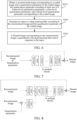
- FIG. 6 shows a flowchart of a deep learning-based filtering method according to an embodiment of this disclosure.
- the deep learning-based filtering method may be performed by a device having a processing function such as computing and storage.
- the deep learning-based filtering method may be performed by a terminal device or a server.
- the deep learning-based filtering method includes at least step S610 to step S630. A detailed description is as follows.
- step S610 a reconstructed image corresponding to a coded image and a quantization parameter of the coded image are obtained.
- the quantization parameter includes at least one of a frame-level quantization parameter, a slice-level quantization parameter, and a block-level quantization parameter corresponding to the coded image.
- the reconstructed image corresponding to the coded image is an image generated by superimposing a reconstructed residual image obtained after inverse quantization and inverse transform processing and a prediction image.
- the reconstructed image is an image signal s k ⁇ x y generated by superimposing a prediction image signal ⁇ k [ x , y ] and a reconstructed residual signal u ' k [ x , y ].
- the quantization parameter of the coded image may also include a sequence-level quantization parameter corresponding to the coded image.
- a video image frame sequence includes a series of image frames.
- Each image frame may be further divided into slices, which in turn may be divided into a series of LCUs (or CTUs).
- the LCU includes a number of CUs.
- the video image frame is coded in units of blocks at the time of coding.
- the MB may be further divided into a plurality of prediction blocks which may be used for predictive coding.
- the basic concepts of coding units (CU), prediction units (PU) and transform units (TU) are used to functionally divide a variety of block units, and a brand-new tree-based structure is used for description.
- the CU may be divided into smaller CUs according to a quadtree, and the smaller CU may continue to be divided to form a quadtree structure.
- the blocks in the embodiments of this disclosure may be CUs, or smaller blocks than CUs, such as smaller blocks obtained by dividing CUs.
- the sequence-level quantization parameter is sequence-QP, and an image sequence shares the same sequence-level quantization parameter. That is, for image frames in an image sequence, the corresponding sequence-level quantization parameters are the same.
- the sequence-level quantization parameters corresponding to different image sequences may or may not be the same.
- the frame-level quantization parameter is frame-QP, and is a quantization parameter corresponding to each image frame.
- the quantization parameters corresponding to different image frames may or may not be the same.
- the slice-level quantization parameter is slice-QP, and blocks in one slice share the same slice-level quantization parameter. That is, for blocks in one slice, the corresponding block-level quantization parameters are the same.
- the sequence-level quantization parameters corresponding to different slices may or may not be the same.
- the block-level quantization parameter is block-QP, and the quantization parameters corresponding to different blocks may or may not be the same.
- the slice-level quantization parameter and the frame-level quantization parameter refer to the same parameter.
- step S620 an input to a deep learning filter is generated according to the reconstructed image and the quantization parameter of the coded image.
- layer combination may be performed on the reconstructed image and the quantization parameter, and a result of the layer combination may be determined as the input to the deep learning filter. As shown in FIG. 7 , the reconstructed image and the quantization parameter may be combined as one layer, and then inputted into the deep learning filter.
- the deep learning filter includes a convolutional unit, a residual unit, and a shuffle unit connected in sequence.
- the convolutional unit includes a convolutional layer (conv) and a parametric rectified linear unit (prelu).
- the residual unit includes N residual blocks connected in sequence.
- the shuffle unit is a shuffle unit.
- the shuffle unit is capable of performing a shuffle () function to shuffle elements in an array in a random order, where the image is up-sampled by shuffling.
- the deep learning filter includes a convolutional unit, a residual unit, and a shuffle unit connected in sequence.
- the residual unit includes N residual blocks connected in sequence.
- the shuffle unit is a shuffle unit.
- reference information corresponding to the reconstructed image may be determined.
- the reference information includes at least one of block partitioning information and a prediction image. Then a convolutional operation is performed on the reference information to obtain features of the reference information, and then the input to the deep learning filter is generated according to the features of the reference information, features of the reconstructed image, and the quantization parameter.
- the reference information includes block partitioning information and a prediction image
- the features extracted respectively for the prediction image, the block partitioning information and the reconstructed image, and the quantization parameter are inputted into the deep learning filter.
- the quantization parameter in the embodiment shown in FIG. 9 may be a sequence-level quantization parameter and a slice-level quantization parameter. As described above, if an image frame is divided into a slice, the quantization parameter in the embodiment shown in FIG. 9 may be a sequence-level quantization parameter and a frame-level quantization parameter.
- the deep learning filter includes a convolutional unit, a residual unit, and a shuffle unit connected in sequence.
- the residual unit includes N residual blocks connected in sequence.
- the shuffle unit is a shuffle unit.
- the features of the quantization parameter may be first extracted by the convolutional unit, and then inputted into the deep learning filter together with the features extracted for the reference information.
- the reference information includes, for example, block partitioning information and a prediction image.
- the reference information may be only the block partitioning information or the prediction image. If the reference information does not include the prediction image, the embodiment shown in FIG. 9 and the modified embodiment thereof may remove a part of feature extraction of the prediction image by the convolutional unit. If the reference information does not include the block partitioning information, the embodiment shown in FIG. 9 and the modified embodiment thereof may remove a part of feature extraction of the block partitioning information by the convolutional unit.
- the block partitioning information may be an image generated according to a block partitioning result, and for example, may include at least one of the following images: a binary image generated according to a block partitioning boundary; a binary image generated according to a filtering boundary of a deblocking filter; or a block partitioning average image obtained by averaging in the same block as values of all sample points within the block according to a block partitioning result for a to-be-filtered reconstructed image.
- the N residual blocks included in the residual unit may be any positive integer number (such as 1, 2, or 3) of residual blocks.
- the residual block in an embodiment of this disclosure may structurally include: a first convolutional layer (with a convolution kernel size 1 ⁇ 1), a parametric rectified linear unit, and a second convolutional layer (with a convolution kernel size 3 ⁇ 3) connected in sequence.
- a block input of the residual block is a layer input of the first convolutional layer, and a layer output of the second convolutional layer is superimposed with the layer input of the first convolutional layer to generate a block output of the residual block.
- the residual block in an embodiment of this disclosure may structurally include: a first convolutional layer (with a convolution kernel size 1 ⁇ 1), a parametric rectified linear unit, a second convolutional layer (with a convolution kernel size 3 ⁇ 3), and a convolutional block attention module (CBAM) connected in sequence.
- a block input of the residual block is a layer input of the first convolutional layer, and a module output of the convolutional block attention module is superimposed with the layer input of the first convolutional layer to generate a block output of the residual block.
- the residual block in an embodiment of this disclosure may structurally include: a first convolutional layer (with a convolution kernel size 1 ⁇ 1), a parametric rectified linear unit, a third convolutional layer (with a convolution kernel size 1 ⁇ 1), and a second convolutional layer (with a convolution kernel size 3 ⁇ 3) connected in sequence.
- a convolution kernel of the first convolutional layer has the same size as a convolution kernel of the third convolutional layer
- a block input of the residual block is a layer input of the first convolutional layer
- a layer output of the second convolutional layer is superimposed with the layer input of the first convolutional layer to generate a block output of the residual block.
- the residual block in an embodiment of this disclosure may structurally include: a first convolutional layer (with a convolution kernel size 1 ⁇ 1), a parametric rectified linear unit, a third convolutional layer (with a convolution kernel size 1 ⁇ 1), a second convolutional layer (with a convolution kernel size 3 ⁇ 3), and a convolutional block attention module connected in sequence.
- a convolution kernel of the first convolutional layer has the same size as a convolution kernel of the third convolutional layer
- a block input of the residual block is a lay input of the first convolutional layer
- a module output of the convolutional block attention module is superimposed with the layer input of the first convolutional layer to generate a block output of the residual block.
- one or more residual blocks may be included in the residual unit, and each residual block may adopt any one of the foregoing structures.
- the number of convolutional layers and prelu layers included in the convolutional unit of the deep learning filter may be set according to actual needs, and the number of convolutional layers and prelu layers included in the residual block may also be set according to actual needs. Meanwhile, the number of channels of different convolutional layers may or may not be the same.
- a filtered image corresponding to the reconstructed image is generated by the deep learning filter and in response to the input.
- the same parameter as that in applications is used as an input when the deep learning filter is trained.
- the quantization parameter includes at least one of a frame-level quantization parameter, a slice-level quantization parameter, and a block-level quantization parameter, which are specifically adjusted according to a use scenario of the deep learning filter, namely, matching a parameter used by the deep learning filter when used) need to be obtained.
- an input for training is generated according to the sample reconstructed image and the quantization parameter, and the obtained input is inputted into the deep learning filter.
- the parameters of the deep learning filter are adjusted according to a loss value between an output of the deep learning filter and an expected filtering result image corresponding to the sample reconstructed image, and the process is repeated until the deep learning filter satisfies a convergence condition.
- a video coding method is also provided in the embodiments of this disclosure.
- the video coding method may be performed by a device having a processing function such as computing and storage.
- the video coding method may be performed by a terminal device or a server.
- the specific flow is shown in FIG. 14 , and includes the following steps S1410 to S1440.
- step S1410 a reconstructed image corresponding to a coded image and a quantization parameter of the coded image are obtained.
- the quantization parameter includes at least one of a frame-level quantization parameter, a slice-level quantization parameter, and a block-level quantization parameter corresponding to the coded image.
- step S610 details of this step may be referred to the foregoing step S610 and will not be described again.
- step S1420 an input to a deep learning filter is generated according to the reconstructed image and the quantization parameter of the coded image.
- step S620 details of this step may be referred to the foregoing step S620 and will not be described again.
- step S1430 a filtered image corresponding to the reconstructed image is generated by the deep learning filter and in response to the input.
- step S1440 a prediction image of a next frame of video image is generated based on the filtered image, and the next frame of video image is coded based on the prediction image.
- the filtered image is used as a next frame of reference image to perform motion estimation and motion compensation prediction. Then a next frame of prediction image signal is obtained based on a result of motion compensation prediction and a result of intra-frame prediction, and the flow shown in FIG. 3 continues to be repeated until coding of a video image is completed.
- a video decoding method is also provided in the embodiments of this disclosure.
- the video decoding method may be performed by a device having a processing function such as computing and storage.
- the video decoding method may be performed by a terminal device or a server.
- the specific flow is shown in FIG. 15 , and includes the following steps S1510 to S1540.
- step S1510 a reconstructed image corresponding to a coded image and a quantization parameter of the coded image are obtained.
- the quantization parameter includes at least one of a frame-level quantization parameter, a slice-level quantization parameter, and a block-level quantization parameter corresponding to the coded image.
- step S610 details of this step may be referred to the foregoing step S610 and will not be described again.
- step S1520 an input to a deep learning filter is generated according to the reconstructed image and the quantization parameter of the coded image.
- step S620 details of this step may be referred to the foregoing step S620 and will not be described again.
- step S1530 a filtered image corresponding to the reconstructed image is generated by the deep learning filter and in response to the input.
- step S1540 a prediction image of a next frame of video image is generated based on the filtered image, and a video stream is decoded based on the generated prediction image.
- motion estimation and motion compensation prediction may be performed on the filtered image as a next frame of reference image. Then a next frame of prediction image signal is obtained based on a result of motion compensation prediction and a result of intra-frame prediction.
- the prediction image signal is superimposed again with a reconstructed residual signal obtained by performing inverse quantization and inverse transform processing to generate a next frame of reconstructed image information, and this process is repeated to realize the decoding processing of a video stream.
- a fine-grained quantization parameter (such as at least one of a frame-level quantization parameter, a slice-level quantization parameter, and a block-level quantization parameter) directly affecting image quality may be used as an input to a deep learning filter, and then the recognition accuracy of the deep learning filter on an inputted reconstructed image can be improved by introducing the fine-grained quantization parameter, thereby improving a filtering effect and being advantageous for improving video coding and decoding efficiency.
- FIG. 16 shows a block diagram of a deep learning-based filtering apparatus according to an embodiment of this disclosure.
- the deep learning-based filtering apparatus may be disposed in a device having a processing function such as computing and storage.
- the deep learning-based filtering apparatus may be disposed in a terminal device or a server.
- a deep learning-based filtering apparatus 1600 includes: an obtaining unit 1602, a generation unit 1604, and a processing unit 1606.
- the obtaining unit 1602 is configured to obtain a reconstructed image corresponding to a coded image and a quantization parameter of the coded image.
- the quantization parameter includes at least one of a frame-level quantization parameter, a slice-level quantization parameter, and a block-level quantization parameter corresponding to the coded image.
- the generation unit 1604 is configured to generate an input to a deep learning filter according to the reconstructed image and the quantization parameter.
- the processing unit 1606 is configured to input the input to the deep learning filter to obtain a filtered image that is outputted by the deep learning filter and corresponds to the reconstructed image.
- the quantization parameter further includes: a sequence-level quantization parameter corresponding to the coded image.
- the generation unit 1604 is configured to: perform layer combination on the reconstructed image and the quantization parameter, and determining a result of the layer combination as the input to the deep learning filter.
- the generation unit 1604 is configured to: perform a point multiplication operation on the reconstructed image and the quantization parameter to obtain a point multiplication operation result; perform a convolutional operation on the point multiplication operation result to obtain features of the reconstructed image; and generate the input to the deep learning filter according to the features obtained by performing the convolutional operation and features extracted from the reconstructed image.
- the generation unit 1604 is configured to: determine reference information corresponding to the reconstructed image, the reference information including at least one of block partitioning information and a prediction image; perform a convolutional operation on the reference information to obtain features of the reference information; and generate the input to the deep learning filter according to the features of the reference information, features of the reconstructed image, and the quantization parameter.
- the deep learning filter includes a convolutional unit, a residual unit, and a shuffle unit connected in sequence.
- the residual unit includes at least one residual block.
- the residual unit includes a plurality of residual blocks
- the number of channels of the plurality of residual blocks is the same, or the number of channels of each of the residual blocks is not exactly the same.
- one of the residual blocks includes: a first convolutional layer, a parametric rectified linear unit, and a second convolutional layer connected in sequence.
- a block input of the residual block is a layer input of the first convolutional layer, and a layer output of the second convolutional layer is superimposed with the layer input of the first convolutional layer to generate a block output of the residual block.
- one of the residual blocks includes: a first convolutional layer, a parametric rectified linear unit, a second convolutional layer, and a convolutional block attention module connected in sequence.
- a block input of the residual block is a layer input of the first convolutional layer, and a module output of the convolutional block attention module is superimposed with the layer input of the first convolutional layer to generate a block output of the residual block.
- one of the residual blocks includes: a first convolutional layer, a parametric rectified linear unit, a third convolutional layer, and a second convolutional layer connected in sequence.
- a convolution kernel of the first convolutional layer has the same size as a convolution kernel of the third convolutional layer
- a block input of the residual block is a layer input of the first convolutional layer
- a layer output of the second convolutional layer is superimposed with the layer input of the first convolutional layer to generate a block output of the residual block.
- one of the residual blocks includes: a first convolutional layer, a parametric rectified linear unit, a third convolutional layer, a second convolutional layer, and a convolutional block attention module connected in sequence.
- a convolution kernel of the first convolutional layer has the same size as a convolution kernel of the third convolutional layer
- a block input of the residual block is a layer input of the first convolutional layer
- a module output of the convolutional block attention module is superimposed with the layer input of the first convolutional layer to generate a block output of the residual block.
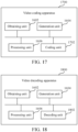
- FIG. 17 shows a block diagram of a video coding apparatus according to an embodiment of this disclosure.
- the video coding apparatus may be disposed in a device having a processing function such as computing and storage.
- the video coding apparatus may be disposed in a terminal device or a server.
- a video coding apparatus 1700 includes: an obtaining unit 1602, a generation unit 1604, a processing unit 1606, and a coding unit 1702.
- the obtaining unit 1602 is configured to obtain a reconstructed image corresponding to a coded image and a quantization parameter of the coded image.
- the quantization parameter includes at least one of a frame-level quantization parameter, a slice-level quantization parameter, and a block-level quantization parameter corresponding to the coded image.
- the generation unit 1604 is configured to generate an input to a deep learning filter according to the reconstructed image and the quantization parameter.
- the processing unit 1606 is configured to input the input to the deep learning filter to obtain a filtered image that is outputted by the deep learning filter and corresponds to the reconstructed image.
- the coding unit 1702 is configured to generate a prediction image of a next frame of video image based on the filtered image, and code the next frame of video image based on the prediction image.
- FIG. 18 shows a block diagram of a video decoding apparatus according to an embodiment of this disclosure.
- the video decoding apparatus may be disposed in a device having a processing function such as computing and storage.
- the video decoding apparatus may be disposed in a terminal device or a server.
- a video decoding apparatus 1800 includes: an obtaining unit 1602, a generation unit 1604, a processing unit 1606, and a decoding unit 1802.
- the obtaining unit 1602 is configured to obtain a reconstructed image corresponding to a coded image and a quantization parameter of the coded image.
- the quantization parameter includes at least one of a frame-level quantization parameter, a slice-level quantization parameter, and a block-level quantization parameter corresponding to the coded image.
- the generation unit 1604 is configured to generate an input to a deep learning filter according to the reconstructed image and the quantization parameter.
- the processing unit 1606 is configured to input the input to the deep learning filter to obtain a filtered image that is outputted by the deep learning filter and corresponds to the reconstructed image.
- the decoding unit 1802 is configured to generate a prediction image of a next frame of video image based on the filtered image, and decode a video stream based on the prediction image.
- FIG. 19 is a schematic structural diagram of a computer system adapted to implement an electronic device according to an embodiment of this disclosure.
- a computer system 1900 of an electronic device shown in FIG. 19 is merely an example and may not pose any limitation on the scope of functionality or use of the embodiments of this disclosure.
- the computer system 1900 includes a central processing unit (CPU) 1901, which may perform various suitable actions and processing based on a program stored in a read-only memory (ROM) 1902 or a program loaded from a storage portion 1908 into a random access memory (RAM) 1903, for example, perform the method described in the foregoing embodiments.
- ROM read-only memory
- RAM random access memory
- various programs and data required for system operation are also stored.
- the CPU 1901, the ROM 1902, and the RAM 1903 are connected to each other through a bus 1904.
- An input/output (I/O) interface 1905 is also connected to the bus 1904.
- the following components are connected to the I/O interface 1905: an input portion 1906 including a keyboard, a mouse, and the like; an output portion 1907 including, for example, a cathode ray tube (CRT), a liquid crystal display (LCD), a speaker, and the like; a storage portion 1908 including a hard disk, and the like; and a communication portion 1909 including, for example, a network interface card such as a local area network (LAN) card and a modem.
- the communication portion 1909 performs communication processing via a network such as the Internet.
- a driver 1910 is also connected to the I/O interface 1905 as required.
- a detachable medium 1911 such as a magnetic disk, an optical disk, a magneto-optical disk, or a semiconductor memory, is installed on the driver 1910 as needed so that a computer program read therefrom is installed into the storage portion 1908 as required.
- the processes described in the following by referring to the flowcharts may be implemented as computer software programs.
- the embodiments of this disclosure include a computer program product.
- the computer program product includes a computer program stored in a computer-readable medium.
- the computer program includes a computer program used for performing a method shown in the flowchart.
- the computer program may be downloaded and installed over the network through the communication portion 1909, and/or installed from the detachable medium 1911.
- the various functions defined in the system of this disclosure are executed.
- the computer-readable medium shown in the embodiments of this disclosure may be a computer-readable signal medium or a computer-readable storage medium or any combination thereof.
- the computer-readable storage medium may be, for example, but is not limited to, an electric, magnetic, optical, electromagnetic, infrared, or semi-conductive system, apparatus, or component, or any combination thereof.
- the computer-readable storage medium may include, but are not limited to: an electrical connector having one or more wires, a portable computer disk, a hard disk, a random access memory (RAM), a read-only memory (ROM), an erasable programmable read only memory (EPROM), a flash memory, an optical fiber, a compact disc read-only memory (CD-ROM), an optical storage device, a magnetic storage device, or any suitable combination thereof.
- the computer-readable storage medium may be any tangible medium containing or storing a program, and the program may be used by or used in combination with an instruction execution system, an apparatus, or a device.
- the computer-readable signal medium may include a data signal transmitted in a baseband or as part of a carrier, and carries a computer-readable computer program therein.
- a data signal propagated in such a way may assume a plurality of forms, including, but not limited to, an electromagnetic signal, an optical signal, or any appropriate combination thereof.
- the computer-readable signal medium may be further any computer-readable medium in addition to a computer-readable storage medium.
- the computer-readable medium may send, propagate, or transmit a program that is used by or used in conjunction with an instruction execution system, an apparatus, or a device.
- a computer program contained on the computer-readable medium may be transmitted over any suitable medium including, but not limited to: a wireless manner, a wired manner, or any suitable combination thereof.
- Each box in a flowchart or a block diagram may represent a module, a program segment, or a part of code.
- the module, the program segment, or the part of code includes one or more executable instructions used for implementing specified logic functions.
- the functions labeled in the blocks may occur out of the order labeled in the accompanying drawings. For example, actually two boxes shown in succession may be performed basically in parallel, and sometimes the two boxes may be performed in a reverse sequence. This is determined by a related function.
- Each box in a block diagram and/or a flowchart and a combination of boxes in the block diagram and/or the flowchart may be implemented by using a dedicated hardware-based system configured to perform a specified function or operation, or may be implemented by using a combination of dedicated hardware and a computer instruction.
- a unit described in the embodiments of this disclosure may be implemented in a software manner, or may be implemented in a hardware manner, and the unit described may also be disposed in a processor.
- the names of these units do not, in some cases, constitute a limitation on the units.
- this disclosure also provides a computer-readable medium.
- the computer-readable medium may be included in the electronic device described in the foregoing embodiments.
- the computer-readable medium may alternatively exist separately and is not fitted into the electronic device.
- the computer-readable medium carries one or more programs. The one or more programs, when executed by the electronic device, enable the electronic device to implement the method described in the foregoing embodiments.
- the exemplary implementations described herein may be implemented by using software, or may be implemented by combining software and necessary hardware. Therefore, the technical solutions of the implementations of this disclosure may be implemented in a form of a software product.
- the software product may be stored in a non-volatile storage medium (which may be a CD-ROM, a USB flash drive, a removable hard disk, or the like) or on the network, including several instructions for instructing a computing device (which may be a personal computer, a server, a touch terminal, a network device, or the like) to perform the methods according to the implementations of this disclosure.
Landscapes
- Engineering & Computer Science (AREA)
- Physics & Mathematics (AREA)
- Theoretical Computer Science (AREA)
- Multimedia (AREA)
- Signal Processing (AREA)
- General Physics & Mathematics (AREA)
- Data Mining & Analysis (AREA)
- Molecular Biology (AREA)
- Biophysics (AREA)
- Computational Linguistics (AREA)
- Artificial Intelligence (AREA)
- Evolutionary Computation (AREA)
- General Health & Medical Sciences (AREA)
- Biomedical Technology (AREA)
- Computing Systems (AREA)
- General Engineering & Computer Science (AREA)
- Life Sciences & Earth Sciences (AREA)
- Mathematical Physics (AREA)
- Software Systems (AREA)
- Health & Medical Sciences (AREA)
- Compression Or Coding Systems Of Tv Signals (AREA)
Abstract
Description
- This application claims priority to
Chinese Patent Application No. 202111144704.2, entitled "FILTERING METHOD AND APPARATUS, ENCODING METHOD AND APPARATUS, DECODING METHOD AND APPARATUS, COMPUTER-READABLE MEDIUM, AND ELECTRONIC DEVICE" filed to the China National Intellectual Property Administration on September 28, 2021 - This application relates to the technical field of computers and communication, and in particular to filtering, coding and decoding methods and apparatuses, a computer-readable medium, and an electronic device.
- In the field of video coding and decoding, after a prediction image and a reconstructed residual image are superimposed to generate a reconstructed image, it may be required to perform loop filtering on the reconstructed image in order to obtain an image with a better quality since the reconstructed image may be distorted. In the loop filtering, how to improve a filtering effect so as to improve coding and decoding efficiency is a technical problem to be solved.
- Embodiments of this disclosure provide filtering, coding and decoding methods and apparatuses, a computer-readable medium, and an electronic device, which can improve a filtering effect at least to a certain extent, and thus are advantageous for improving video coding and decoding efficiency.
- Other characteristics and advantages of this disclosure become obvious through the following detailed descriptions or partially learned through the practice of this disclosure.
- According to one aspect of the embodiments of this disclosure, a deep learning-based filtering method is provided. The method includes: obtaining a reconstructed image corresponding to a coded image and a quantization parameter of the coded image, the quantization parameter including at least one of a frame-level quantization parameter, a slice-level quantization parameter, and a block-level quantization parameter corresponding to the coded image; generating an input to a deep learning filter according to the reconstructed image and the quantization parameter; and generating, by the deep learning filter and in response to the input, a filtered image corresponding to the reconstructed image.
- According to one aspect of the embodiments of this disclosure, a video coding method is provided. The method includes: obtaining a reconstructed image corresponding to a coded image and a quantization parameter of the coded image, the quantization parameter including at least one of a frame-level quantization parameter, a slice-level quantization parameter, and a block-level quantization parameter corresponding to the coded image; generating an input to a deep learning filter according to the reconstructed image and the quantization parameter; generating, by the deep learning filter and in response to the input, a filtered image corresponding to the reconstructed image; and generating a prediction image of a next frame of video image based on the filtered image, and coding the next frame of video image based on the prediction image.
- According to one aspect of the embodiments of this disclosure, a video decoding method is provided. The method includes: obtaining a reconstructed image corresponding to a coded image and a quantization parameter of the coded image, the quantization parameter including at least one of a frame-level quantization parameter, a slice-level quantization parameter, and a block-level quantization parameter corresponding to the coded image; generating an input to a deep learning filter according to the reconstructed image and the quantization parameter; generating, by the deep learning filter and in response to the input, a filtered image corresponding to the reconstructed image; and generating a prediction image of a next frame of video image based on the filtered image, and decoding a video stream based on the prediction image.
- According to one aspect of the embodiments of this disclosure, a deep learning-based filtering apparatus is provided. The apparatus includes: an obtaining unit, configured to obtain a reconstructed image corresponding to a coded image and a quantization parameter of the coded image, the quantization parameter including at least one of a frame-level quantization parameter, a slice-level quantization parameter, and a block-level quantization parameter corresponding to the coded image; a generation unit, configured to generate an input to a deep learning filter according to the reconstructed image and the quantization parameter; and a processing unit, configured to generate, by the deep learning filter and in response to the input, a filtered image corresponding to the reconstructed image.
- According to one aspect of the embodiments of this disclosure, a video coding apparatus is provided. The apparatus includes: an obtaining unit, configured to obtain a reconstructed image corresponding to a coded image and a quantization parameter of the coded image, the quantization parameter including at least one of a frame-level quantization parameter, a slice-level quantization parameter, and a block-level quantization parameter corresponding to the coded image; a generation unit, configured to generate an input to a deep learning filter according to the reconstructed image and the quantization parameter; a processing unit, configured to generate, by the deep learning filter and in response to the input, a filtered image corresponding to the reconstructed image; and a coding unit, configured to generate a prediction image of a next frame of video image based on the filtered image, and code the next frame of video image based on the prediction image.
- According to one aspect of the embodiments of this disclosure, a video decoding apparatus is provided. The apparatus includes: an obtaining unit, configured to obtain a reconstructed image corresponding to a coded image and a quantization parameter of the coded image, the quantization parameter including at least one of a frame-level quantization parameter, a slice-level quantization parameter, and a block-level quantization parameter corresponding to the coded image; a generation unit, configured to generate an input to a deep learning filter according to the reconstructed image and the quantization parameter; a processing unit, configured to generate, by the deep learning filter and in response to the input, a filtered image corresponding to the reconstructed image; and a decoding unit, configured to generate a prediction image of a next frame of video image based on the filtered image, and decode a video stream based on the prediction image.
- According to one aspect of the embodiments of this disclosure, a computer-readable medium is provided. The computer-readable medium stores a computer program which, when executed by a processor, implements the deep learning-based filtering method, the video coding method or the video decoding method as described in the foregoing embodiments.
- According to one aspect of the embodiments of this disclosure, an electronic device is provided. The electronic device includes: one or more processors; and a storage apparatus, configured to store one or more programs which, when executed by the one or more processors, enable the electronic device to implement the deep learning-based filtering method, the video coding method or the video decoding method as described in the foregoing embodiments.
- According to one aspect of the embodiments of this disclosure, a computer program product or a computer program is provided. The computer program product or the computer program includes computer instructions stored in a computer-readable storage medium. A processor of a computer device reads the computer instructions from the computer-readable storage medium. The processor executes the computer instructions to enable the computer device to perform the deep learning-based filtering method, the video coding method or the video decoding method as described in the foregoing embodiments.
- In the technical solutions provided by some embodiments of this disclosure, a reconstructed image corresponding to a coded image and a quantization parameter of the coded image are obtained, and the quantization parameter includes at least one of a frame-level quantization parameter, a slice-level quantization parameter, and a block-level quantization parameter corresponding to the coded image. Then an input parameter of a deep learning filter is generated according to the reconstructed image and the quantization parameter, and the input parameter is inputted to the deep learning filter to obtain a filtered image that is outputted by the deep learning filter and corresponds to the reconstructed image. Therefore, a fine-grained quantization parameter (namely, at least one of the frame-level quantization parameter, the slice-level quantization parameter, and the block-level quantization parameter) directly affecting image quality may be used as an input of the deep learning filter, and then the recognition accuracy of the deep learning filter on the inputted reconstructed image can be improved by introducing the fine-grained quantization parameter, thereby improving a filtering effect and being advantageous for improving video coding and decoding efficiency.
- It is to be understood that both the foregoing general description and the following detailed description are exemplary and explanatory only and are not restrictive of this disclosure.
- The accompanying drawings, which are incorporated in and constitute a part of this specification, illustrate embodiments consistent with this disclosure and, together with the specification, serve to explain the principles of this disclosure. It is obvious that the accompanying drawings in the following description are only some embodiments of this disclosure, and those of ordinary skill in the art may also obtain other accompanying drawings according to these accompanying drawings without involving any inventive effort. In the accompanying drawings:
-
FIG. 1 shows a schematic diagram of an exemplary system architecture to which a technical solution according to an embodiment of this disclosure may be applied. -
FIG. 2 shows a schematic diagram of placement modes of an exemplary video coding apparatus and an exemplary video decoding apparatus in a streaming transmission system. -
FIG. 3 shows a basic flowchart of an exemplary video coder. -
FIG. 4 shows a schematic diagram of an exemplary CNNLF-based filtering processing. -
FIG. 5 shows a schematic diagram of an exemplary frame-level quantization parameter of a sequence in an RA coding mode. -
FIG. 6 shows a flowchart of a deep learning-based filtering method according to an embodiment of this disclosure. -
FIG. 7 shows a schematic diagram of generating an input to a deep learning filter based on a reconstructed image and a quantization parameter of a coded image according to an embodiment of this disclosure. -
FIG. 8 shows a schematic diagram of generating an input to a deep learning filter based on a reconstructed image and a quantization parameter of a coded image according to another embodiment of this disclosure. -
FIG. 9 shows a schematic diagram of generating an input to a deep learning filter based on a reconstructed image and a quantization parameter of a coded image according to another embodiment of this disclosure. -
FIG. 10 shows a schematic structural diagram of a residual block according to an embodiment of this disclosure. -
FIG. 11 shows a schematic structural diagram of a residual block according to another embodiment of this disclosure. -
FIG. 12 shows a schematic structural diagram of a residual block according to another embodiment of this disclosure. -
FIG. 13 shows a schematic structural diagram of a residual block according to another embodiment of this disclosure. -
FIG. 14 shows a flowchart of a video coding method according to an embodiment of this disclosure. -
FIG. 15 shows a flowchart of a video decoding method according to an embodiment of this disclosure. -
FIG. 16 shows a block diagram of a deep learning-based filtering apparatus according to an embodiment of this disclosure. -
FIG. 17 shows a block diagram of a video coding apparatus according to an embodiment of this disclosure. -
FIG. 18 shows a block diagram of a video decoding apparatus according to an embodiment of this disclosure. -
FIG. 19 is a schematic structural diagram of a computer system adapted to implement an electronic device according to an embodiment of this disclosure. - Example implementations will now be described with reference to the accompanying drawings. However, the example implementations can be implemented in various forms and may not be construed as being limited to these examples. Rather, these implementations are provided in order that this disclosure will be more thorough and complete, and the concept of the example implementations will be conveyed to those skilled in the art completely.
- Furthermore, the features, structures, or characteristics described herein may be combined in any suitable manner in one or more embodiments. In the following description, exemplary details are set forth in order to provide a understanding of some embodiments of this disclosure. However, it is noted that not all of the specific details of the embodiments may be used, that one or more specific details may be omitted, or that other methods, elements, apparatuses, steps, and the like may be employed in practicing the technical solutions of this disclosure.
- The block diagrams shown in the accompanying drawings are merely functional entities and do not necessarily correspond to physically independent entities. That is, the functional entities may be implemented in a software form, or in one or more hardware modules or integrated circuits, or in different networks and/or processor apparatuses and/or microcontroller apparatuses.
- The flowcharts shown in the accompanying drawings are merely exemplary descriptions, do not need to include all content and operations/steps, and do not need to be performed in the described orders either. For example, some operations/steps may be further divided, while some operations/steps may be combined or partially combined. Therefore, an actual execution order may change according to an actual case.
- "A plurality" mentioned herein means two or more than two. "And/or" describes an association relationship between associated objects, and represents that three relationships may exist. For example, A and/or B may represent the following three cases: Only A exists, both A and B exist, and only B exists. The character "/" generally represents that contextual objects are in an "or" relationship.
-
FIG. 1 shows a schematic diagram of an exemplary system architecture to which a technical solution according to an embodiment of this disclosure may be applied. - As shown in
FIG. 1 , asystem architecture 100 includes a plurality of terminal apparatuses. The terminal apparatuses may communicate with each other through, for example, anetwork 150. For example, thesystem architecture 100 may include a firstterminal apparatus 110 and a secondterminal apparatus 120 interconnected through thenetwork 150. In the embodiment ofFIG. 1 , the firstterminal apparatus 110 and the secondterminal apparatus 120 perform unidirectional data transmission. - For example, the first
terminal apparatus 110 may code video data (for example, a video picture stream acquired by the terminal apparatus 110) for transmission over thenetwork 150 to the secondterminal apparatus 120. The coded video data is transmitted in one or more coded video streams. The secondterminal apparatus 120 may receive the coded video data from thenetwork 150, decode the coded video data to restore the video data, and display a video picture according to the restored video data. - In an embodiment of this disclosure, the
system architecture 100 may include a thirdterminal apparatus 130 and a fourthterminal apparatus 140 that perform bi-directional transmission of the coded video data. The bi-directional transmission may occur, for example, during a video conference. For bi-directional data transmission, each of the thirdterminal apparatus 130 and the fourthterminal apparatus 140 may code video data (for example, a video picture stream acquired by the terminal apparatus) for transmission over thenetwork 150 to the other of the thirdterminal apparatus 130 and the fourthterminal apparatus 140. Each of the thirdterminal apparatus 130 and the fourthterminal apparatus 140 may also receive the coded video data transmitted by the other of the thirdterminal apparatus 130 and the fourthterminal apparatus 140, may decode the coded video data to restore the video data, and may display a video picture on an accessible display apparatus according to the restored video data. - In the embodiment of
FIG. 1 , the firstterminal apparatus 110, the secondterminal apparatus 120, the thirdterminal apparatus 130, and the fourthterminal apparatus 140 may be a server, a personal computer and a smart phone, but the principles disclosed in this disclosure may not be limited thereto. Embodiments disclosed in this disclosure are applicable to laptop computers, tablet computers, media players, and/or dedicated video conferencing devices. Thenetwork 150 represents any number of networks that communicate the coded video data between the firstterminal apparatus 110, the secondterminal apparatus 120, the thirdterminal apparatus 130, and the fourthterminal apparatus 140, including, for example, wired and/or wireless communication networks. Thecommunication network 150 may exchange data in circuit-switched and/or packet-switched channels. The network may include a telecommunications network, a local area network, a wide area network, and/or the Internet. For purposes of this disclosure, unless explained below, the architecture and topology of thenetwork 150 may be insignificant to the operation disclosed in this disclosure. - In an embodiment of this disclosure,
FIG. 2 shows placement modes of a video coding apparatus and a video decoding apparatus in a streaming transmission environment. The subject matter disclosed in this disclosure is equally applicable to other video-enabled applications including, for example, video conferencing, digital television (TV), storing compressed video on digital media including CD, DVD, memory sticks, and the like. - A streaming transmission system may include an
acquisition subsystem 213. Theacquisition subsystem 213 may include avideo source 201, such as a digital camera. The video source creates an uncompressedvideo picture stream 202. In an embodiment, thevideo picture stream 202 includes samples taken by a digital camera. In contrast to coded video data 204 (or a coded video stream 204), thevideo picture stream 202 is depicted as a bold line to emphasize a high-data-volume video picture stream. Thevideo picture stream 202 may be processed by anelectronic apparatus 220. Theelectronic apparatus 220 includes avideo coding apparatus 203 coupled to thevideo source 201. Thevideo coding apparatus 203 may include hardware, software, or a combination of hardware and software to realize or implement aspects of the disclosed subject matter as described in more detail below. In contrast to thevideo picture stream 202, the coded video data 204 (or the coded video stream 204) is depicted as a thin line to emphasize low-data-volume coded video data 204 (or the coded video stream 204), which may be stored on astreaming transmission server 205 for future use. One or more streaming transmission client subsystems, such as aclient subsystem 206 and aclient subsystem 208 inFIG. 2 , may access thestreaming transmission server 205 to retrieve acopy 207 and acopy 209 of the codedvideo data 204. Theclient subsystem 206 may include, for example, thevideo decoding apparatus 210 in theelectronic apparatus 230. Thevideo decoding apparatus 210 decodes thecopy 207 of the coded video data and generates an outputvideo picture stream 211 that may be presented on a display 212 (for example, a display screen) or another presentation apparatus. In some streaming transmission systems, the codedvideo data 204,video data 207 and video data 209 (for example, video streams) may be coded according to certain video coding/compression standards. - The
electronic apparatus 220 and theelectronic apparatus 230 may include other components not shown in the figures. For example, theelectronic apparatus 220 may include a video decoding apparatus, and theelectronic apparatus 230 may also include a video coding apparatus. - In an embodiment of this disclosure, taking an international video coding standard: High Efficiency Video Coding (HEVC), versatile video coding (VVC) and a Chinese national video coding standard AVS as examples, when a video frame image is inputted, the video frame image is divided into a number of non-overlapping processing units according to a block size, and each processing unit will perform a similar compression operation. This processing unit is referred to as a coding tree unit (CTU) or a largest coding unit (LCU). The CTU may then be more finely divided to obtain one or more basic coding units (CU). The CU is the most basic element of a coding link.
- Some concepts in coding a CU are introduced below:
- Predictive coding: the predictive coding includes intra-frame prediction, inter-frame prediction and other modes, and after an original video signal is predicted by a selected reconstructed video signal, a residual video signal is obtained. An encoder side needs to determine a corresponding predictive coding mode for the current CU and to inform of a decoder side. The intra-frame prediction means that a predicted signal comes from a region which has been coded and reconstructed in the same image. The inter-frame prediction means that a predicted signal comes from an already coded image (referred to as a reference image) different from a current image.
- Transform & Quantization: after a residual video signal is subjected to transform operations such as discrete Fourier transform (DFT) and discrete cosine transform (DCT), the signal is converted into a transform domain, which is referred to as a transform coefficient. The transform coefficient is further subjected to a lossy quantization operation, and some information is lost, whereby a quantized signal is advantageous for compression expression. In some video coding standards, there may be more than one selectable transform mode. Therefore, the encoder side also needs to select one of the transform modes for the current CU and inform of the decoder side. The degree of refinement of quantization is usually determined by a quantization parameter (QP). A larger value of the QP indicates that coefficients within a larger range of values will be quantized into the same output. Therefore, more distortion and lower code rate will be brought usually. Conversely, a smaller value of the QP indicates that coefficients within a smaller range of values will be quantized into the same output. Therefore, less distortion will be brought usually while corresponding to a higher code rate.
- Entropy coding or statistical coding: a quantized transform domain signal will be statistically compressed and coded according to the frequency of occurrence of each value, and finally a binary (0 or 1) compressed stream will be output. Meanwhile, other information is generated by coding. For example, a selected coding mode, motion vector data, and the like also need to be subjected to entropy coding to reduce the code rate. The statistical coding is a lossless coding mode, which can effectively reduce the code rate required to express the same signal. Common statistical coding modes include variable length coding (VLC) or context adaptive binary arithmetic coding (CABAC).
- The context adaptive binary arithmetic coding (CABAC) process mainly includes three steps: binarization, context modeling, and binary arithmetic coding. After an inputted syntax element is binarized, binary data may be coded through a normal coding mode and a bypass coding mode. The bypass coding mode does not need to assign a specific probability model to each binary bit, and an inputted binary bit bin value is directly coded with a simple bypass coder to speed up the overall coding and decoding. In general, different syntax elements are not completely independent, and the same syntax element has some memorability. Therefore, according to a conditional entropy theory, conditional coding using other coded syntax elements can further improve coding performance compared to independent coding or memoryless coding. These coded information used as conditions are called contexts. In the conventional coding mode, binary bits of the syntax elements enter a context coder in sequence, and the coder assigns an appropriate probability model to each inputted binary bit according to the value of the previously coded syntax element or binary bit. The process is context modeling. A context model corresponding to the syntax element may be located through context index increment (ctxIdxInc) and context index start (ctxIdxStart). After the bin value and the assigned probability model are sent to a binary arithmetic coder for coding, the context model needs to be updated according to the bin value. This is an adaptive process in coding.
- Loop filtering: a transformed and quantized signal is processed by inverse quantization, inverse transform, and predictive compensation to obtain a reconstructed image. The reconstructed image is different from an original image in part of the information due to the effect of quantization. That is, the reconstructed image is distorted. Therefore, the reconstructed image may be filtered by a deblocking filter (DB), a sample adaptive offset (SAO) filter, or an adaptive loop filter (ALF), and the like, thereby effectively reducing the degree of distortion generated by quantization. Since these filtered reconstructed images will be used as references for subsequent coded images to predict future image signals, the foregoing filtering operation is also referred to as loop filtering, namely a filtering operation within a coding loop.
- In an embodiment of this disclosure,
FIG. 3 shows a basic flowchart of a video coder. In this flow, intra-frame prediction is exemplified. A difference operation is performed on an original image signal sk [x, y] and a prediction image signal ŝk [x ,y] to obtain a residual signal uk [x, y]. The residual signal uk [x, y] is transformed and quantized to obtain a quantization coefficient. The quantization coefficient, on the one hand, obtains a coded bit stream through entropy coding, and on the other hand obtains a reconstructed residual signal u' k [x, y] through inverse quantization and inverse transform processing. The prediction image signal ŝ k[x, y] and the reconstructed residual signal u' k [x, y] are superimposed to generate a reconstructed image signal


- The foregoing loop filtering may be implemented based on a convolutional neural network loop filter (CNNLF). A model structure of the CNNLF includes basic modules such as a convolutional layer, an activation function, a full connection layer, and a pooling layer. Model parameters need to be obtained through training. As shown in
FIG. 4 , after the CNNLF is trained, a to-be-filtered image may be inputted into the trained CNNLF, and finally a filtered image may be outputted. - When the CNNLF is used for filtering processing, a related technical solution is to train corresponding data of each sequence-level quantization parameter to obtain a deep learning filter, and then select the corresponding deep learning filter to perform filtering according to a value of the sequence-level quantization parameter. Another related technical solution is to train corresponding data of each (at least two) sequence-level quantization parameter(s) to obtain a deep learning filter, and then select the corresponding deep learning filter to perform filtering according to the value of the sequence-level quantization parameter. These solutions may input the sequence-level quantization parameters to train the deep learning filters, and accordingly, when using the deep learning filters, inputs of the deep learning filters need to contain the sequence-level quantization parameters as well.
- Meanwhile, in a general test configuration of mainstream video coding standards, a random access (RA) mode is taken as an example. As shown in
FIG. 5 , the whole sequence of the RA coding mode has a common sequence-level quantization parameter, each frame has a corresponding frame-level quantization parameter (namely, a-h shown inFIG. 5 ), and the corresponding frame-level quantization parameters of all frames are not completely the same. The frame-level quantization parameters are obtained by adding an offset on the basis of the sequence-level quantization parameter. In order to improve the recognition accuracy of the deep learning filter on the inputted reconstructed image and improve the filtering effect and the video coding and decoding efficiency, the embodiments of this disclosure provide technical solutions of taking a finer-grained frame-level quantization parameter as an input to a deep learning filter, so as to improve the performance of the deep learning filter. - Deep learning belongs to the category of artificial intelligence (AI). Machine learning (ML) is the core of AI, is the fundamental way to make computers intelligent, and is applied in all fields of AI. The deep learning filter in the embodiments of this disclosure is a machine learning/deep learning-based filter.
- The implementation details of the technical solutions of the embodiments of this disclosure are described in detail as follows.
-
FIG. 6 shows a flowchart of a deep learning-based filtering method according to an embodiment of this disclosure. The deep learning-based filtering method may be performed by a device having a processing function such as computing and storage. For example, the deep learning-based filtering method may be performed by a terminal device or a server. Referring toFIG. 6 , the deep learning-based filtering method includes at least step S610 to step S630. A detailed description is as follows. - In step S610, a reconstructed image corresponding to a coded image and a quantization parameter of the coded image are obtained. The quantization parameter includes at least one of a frame-level quantization parameter, a slice-level quantization parameter, and a block-level quantization parameter corresponding to the coded image.
- In an embodiment of this disclosure, the reconstructed image corresponding to the coded image is an image generated by superimposing a reconstructed residual image obtained after inverse quantization and inverse transform processing and a prediction image. For example, in the flow shown in
FIG. 3 , the reconstructed image is an image signal
- In an embodiment of this disclosure, in addition to the frame-level quantization parameter, the slice-level quantization parameter, and the block-level quantization parameter, the quantization parameter of the coded image may also include a sequence-level quantization parameter corresponding to the coded image.
- A video image frame sequence includes a series of image frames. Each image frame may be further divided into slices, which in turn may be divided into a series of LCUs (or CTUs). The LCU includes a number of CUs. The video image frame is coded in units of blocks at the time of coding. There is a macroblock (MB) in some new video coding standards such as standard H.264. The MB may be further divided into a plurality of prediction blocks which may be used for predictive coding. In the HEVC standard, the basic concepts of coding units (CU), prediction units (PU) and transform units (TU) are used to functionally divide a variety of block units, and a brand-new tree-based structure is used for description. For example, the CU may be divided into smaller CUs according to a quadtree, and the smaller CU may continue to be divided to form a quadtree structure. The blocks in the embodiments of this disclosure may be CUs, or smaller blocks than CUs, such as smaller blocks obtained by dividing CUs.
- In an embodiment of this disclosure, the sequence-level quantization parameter is sequence-QP, and an image sequence shares the same sequence-level quantization parameter. That is, for image frames in an image sequence, the corresponding sequence-level quantization parameters are the same. The sequence-level quantization parameters corresponding to different image sequences may or may not be the same.
- The frame-level quantization parameter is frame-QP, and is a quantization parameter corresponding to each image frame. The quantization parameters corresponding to different image frames may or may not be the same.
- The slice-level quantization parameter is slice-QP, and blocks in one slice share the same slice-level quantization parameter. That is, for blocks in one slice, the corresponding block-level quantization parameters are the same. The sequence-level quantization parameters corresponding to different slices may or may not be the same. The block-level quantization parameter is block-QP, and the quantization parameters corresponding to different blocks may or may not be the same.
- If an image frame is divided into a slice, the slice-level quantization parameter and the frame-level quantization parameter refer to the same parameter.
- In step S620, an input to a deep learning filter is generated according to the reconstructed image and the quantization parameter of the coded image.
- In an embodiment of this disclosure, layer combination may be performed on the reconstructed image and the quantization parameter, and a result of the layer combination may be determined as the input to the deep learning filter. As shown in
FIG. 7 , the reconstructed image and the quantization parameter may be combined as one layer, and then inputted into the deep learning filter. - In this embodiment, the deep learning filter includes a convolutional unit, a residual unit, and a shuffle unit connected in sequence. The convolutional unit includes a convolutional layer (conv) and a parametric rectified linear unit (prelu). The residual unit includes N residual blocks connected in sequence. The shuffle unit is a shuffle unit. The shuffle unit is capable of performing a shuffle () function to shuffle elements in an array in a random order, where the image is up-sampled by shuffling.
- In the embodiment shown in
FIG. 7 , the convolutional layer in the convolutional unit preceding the residual unit has a step size s=2. Another convolutional layer may alternatively be disposed between the residual unit and the shuffle unit. This convolutional layer has a step size s=1. - In an embodiment of this disclosure, a point multiplication operation may be performed on the reconstructed image and the quantization parameter to obtain a point multiplication operation result. Then a convolutional operation may be performed on the point multiplication operation result to obtain features of the reconstructed image, and then the input to the deep learning filter may be generated according to the features obtained by performing the convolutional operation and features extracted from the reconstructed image. As shown in
FIG. 8 , after performing the point multiplication operation on the reconstructed image and the quantization parameter, features may be extracted by a convolutional unit (the convolutional unit includes a convolutional layer conv and a parametric rectified linear unit prelu, where the convolutional layer has a step size s=1). The features of the reconstructed image are extracted by a convolutional unit (the convolutional unit includes a convolutional layer conv and a parametric rectified linear unit prelu, where the convolutional layer has a step size s=1), and then the features extracted for the point multiplication operation result and the features extracted for the reconstructed image are inputted into the deep learning filter. - In the embodiment shown in
FIG. 8 , the deep learning filter includes a convolutional unit, a residual unit, and a shuffle unit connected in sequence. The convolutional unit includes a convolutional layer with a step size s=1, a parametric rectified linear unit prelu, and a convolutional layer with a step size s=2. The residual unit includes N residual blocks connected in sequence. The shuffle unit is a shuffle unit. In the embodiment shown inFIG. 8 , a convolutional layer may alternatively be disposed between the residual unit and the shuffle unit. This convolutional layer has a step size s=1. - In an embodiment of this disclosure, reference information corresponding to the reconstructed image may be determined. The reference information includes at least one of block partitioning information and a prediction image. Then a convolutional operation is performed on the reference information to obtain features of the reference information, and then the input to the deep learning filter is generated according to the features of the reference information, features of the reconstructed image, and the quantization parameter.
- As shown in
FIG. 9 , assuming that the reference information includes block partitioning information and a prediction image, features may be extracted for the prediction image, the block partitioning information, and the reconstructed image respectively by a convolutional unit (the convolutional unit includes a convolutional layer conv and a parametric rectified linear unit prelu, where the convolutional layer has a step size s=1). Then the features extracted respectively for the prediction image, the block partitioning information and the reconstructed image, and the quantization parameter are inputted into the deep learning filter. The quantization parameter in the embodiment shown inFIG. 9 may be a sequence-level quantization parameter and a slice-level quantization parameter. As described above, if an image frame is divided into a slice, the quantization parameter in the embodiment shown inFIG. 9 may be a sequence-level quantization parameter and a frame-level quantization parameter. - In the embodiment shown in
FIG. 9 , the deep learning filter includes a convolutional unit, a residual unit, and a shuffle unit connected in sequence. The convolutional unit includes a convolutional layer with a step size s=1, a parametric rectified linear unit prelu, and a convolutional layer with a step size s=2. The residual unit includes N residual blocks connected in sequence. The shuffle unit is a shuffle unit. In the embodiment shown inFIG. 9 , a convolutional layer may alternatively be disposed between the residual unit and the shuffle unit. This convolutional layer has a step size s=1. - As a modified embodiment of the embodiment shown in
FIG. 9 , the features of the quantization parameter may be first extracted by the convolutional unit, and then inputted into the deep learning filter together with the features extracted for the reference information. - In the embodiment shown in
FIG. 9 and the modified embodiment ofFIG. 9 , the reference information includes, for example, block partitioning information and a prediction image. In other embodiments of this disclosure, the reference information may be only the block partitioning information or the prediction image. If the reference information does not include the prediction image, the embodiment shown inFIG. 9 and the modified embodiment thereof may remove a part of feature extraction of the prediction image by the convolutional unit. If the reference information does not include the block partitioning information, the embodiment shown inFIG. 9 and the modified embodiment thereof may remove a part of feature extraction of the block partitioning information by the convolutional unit. - In an embodiment, the block partitioning information may be an image generated according to a block partitioning result, and for example, may include at least one of the following images: a binary image generated according to a block partitioning boundary; a binary image generated according to a filtering boundary of a deblocking filter; or a block partitioning average image obtained by averaging in the same block as values of all sample points within the block according to a block partitioning result for a to-be-filtered reconstructed image.
- In an embodiment of this disclosure, the N residual blocks included in the residual unit may be any positive integer number (such as 1, 2, or 3) of residual blocks.
- As shown in
FIG. 10 , the residual block in an embodiment of this disclosure may structurally include: a first convolutional layer (with aconvolution kernel size 1×1), a parametric rectified linear unit, and a second convolutional layer (with a convolution kernel size 3×3) connected in sequence. A block input of the residual block is a layer input of the first convolutional layer, and a layer output of the second convolutional layer is superimposed with the layer input of the first convolutional layer to generate a block output of the residual block. - As shown in
FIG. 11 , the residual block in an embodiment of this disclosure may structurally include: a first convolutional layer (with aconvolution kernel size 1×1), a parametric rectified linear unit, a second convolutional layer (with a convolution kernel size 3×3), and a convolutional block attention module (CBAM) connected in sequence. A block input of the residual block is a layer input of the first convolutional layer, and a module output of the convolutional block attention module is superimposed with the layer input of the first convolutional layer to generate a block output of the residual block. - As shown in
FIG. 12 , the residual block in an embodiment of this disclosure may structurally include: a first convolutional layer (with aconvolution kernel size 1×1), a parametric rectified linear unit, a third convolutional layer (with aconvolution kernel size 1×1), and a second convolutional layer (with a convolution kernel size 3×3) connected in sequence. A convolution kernel of the first convolutional layer has the same size as a convolution kernel of the third convolutional layer, a block input of the residual block is a layer input of the first convolutional layer, and a layer output of the second convolutional layer is superimposed with the layer input of the first convolutional layer to generate a block output of the residual block. - As shown in
FIG. 13 , the residual block in an embodiment of this disclosure may structurally include: a first convolutional layer (with aconvolution kernel size 1×1), a parametric rectified linear unit, a third convolutional layer (with aconvolution kernel size 1×1), a second convolutional layer (with a convolution kernel size 3 ×3), and a convolutional block attention module connected in sequence. A convolution kernel of the first convolutional layer has the same size as a convolution kernel of the third convolutional layer, a block input of the residual block is a lay input of the first convolutional layer, and a module output of the convolutional block attention module is superimposed with the layer input of the first convolutional layer to generate a block output of the residual block. - In an embodiment of this disclosure, one or more residual blocks may be included in the residual unit, and each residual block may adopt any one of the foregoing structures. The number of convolutional layers and prelu layers included in the convolutional unit of the deep learning filter may be set according to actual needs, and the number of convolutional layers and prelu layers included in the residual block may also be set according to actual needs. Meanwhile, the number of channels of different convolutional layers may or may not be the same.
- With reference to
FIG. 6 , in step S630, a filtered image corresponding to the reconstructed image is generated by the deep learning filter and in response to the input. - In an embodiment of this disclosure, the same parameter as that in applications is used as an input when the deep learning filter is trained. Specifically, in the training stage, a sample reconstructed image and a corresponding quantization parameter (the quantization parameter includes at least one of a frame-level quantization parameter, a slice-level quantization parameter, and a block-level quantization parameter, which are specifically adjusted according to a use scenario of the deep learning filter, namely, matching a parameter used by the deep learning filter when used) need to be obtained. Then an input for training is generated according to the sample reconstructed image and the quantization parameter, and the obtained input is inputted into the deep learning filter. The parameters of the deep learning filter are adjusted according to a loss value between an output of the deep learning filter and an expected filtering result image corresponding to the sample reconstructed image, and the process is repeated until the deep learning filter satisfies a convergence condition.
- On the basis of the deep learning-based filtering method shown in
FIG. 6 , a video coding method is also provided in the embodiments of this disclosure. The video coding method may be performed by a device having a processing function such as computing and storage. For example, the video coding method may be performed by a terminal device or a server. The specific flow is shown inFIG. 14 , and includes the following steps S1410 to S1440. - In step S1410, a reconstructed image corresponding to a coded image and a quantization parameter of the coded image are obtained. The quantization parameter includes at least one of a frame-level quantization parameter, a slice-level quantization parameter, and a block-level quantization parameter corresponding to the coded image.
- For example, details of this step may be referred to the foregoing step S610 and will not be described again.
- In step S1420, an input to a deep learning filter is generated according to the reconstructed image and the quantization parameter of the coded image.
- For example, details of this step may be referred to the foregoing step S620 and will not be described again.
- In step S1430, a filtered image corresponding to the reconstructed image is generated by the deep learning filter and in response to the input.
- In step S1440, a prediction image of a next frame of video image is generated based on the filtered image, and the next frame of video image is coded based on the prediction image.
- In this embodiment, after the filtered image is generated, reference may be made to the flow shown in
FIG. 3 . That is, the filtered image is used as a next frame of reference image to perform motion estimation and motion compensation prediction. Then a next frame of prediction image signal is obtained based on a result of motion compensation prediction and a result of intra-frame prediction, and the flow shown inFIG. 3 continues to be repeated until coding of a video image is completed. - Accordingly, on the basis of the deep learning-based filtering method shown in
FIG. 6 , a video decoding method is also provided in the embodiments of this disclosure. The video decoding method may be performed by a device having a processing function such as computing and storage. For example, the video decoding method may be performed by a terminal device or a server. The specific flow is shown inFIG. 15 , and includes the following steps S1510 to S1540. - In step S1510, a reconstructed image corresponding to a coded image and a quantization parameter of the coded image are obtained. The quantization parameter includes at least one of a frame-level quantization parameter, a slice-level quantization parameter, and a block-level quantization parameter corresponding to the coded image.
- For example, details of this step may be referred to the foregoing step S610 and will not be described again.
- In step S1520, an input to a deep learning filter is generated according to the reconstructed image and the quantization parameter of the coded image.
- For example, details of this step may be referred to the foregoing step S620 and will not be described again.
- In step S1530, a filtered image corresponding to the reconstructed image is generated by the deep learning filter and in response to the input.
- In step S1540, a prediction image of a next frame of video image is generated based on the filtered image, and a video stream is decoded based on the generated prediction image.
- In this embodiment, after a filtered image is generated, motion estimation and motion compensation prediction may be performed on the filtered image as a next frame of reference image. Then a next frame of prediction image signal is obtained based on a result of motion compensation prediction and a result of intra-frame prediction. The prediction image signal is superimposed again with a reconstructed residual signal obtained by performing inverse quantization and inverse transform processing to generate a next frame of reconstructed image information, and this process is repeated to realize the decoding processing of a video stream.
- In the technical solutions of the embodiments of this disclosure, a fine-grained quantization parameter (such as at least one of a frame-level quantization parameter, a slice-level quantization parameter, and a block-level quantization parameter) directly affecting image quality may be used as an input to a deep learning filter, and then the recognition accuracy of the deep learning filter on an inputted reconstructed image can be improved by introducing the fine-grained quantization parameter, thereby improving a filtering effect and being advantageous for improving video coding and decoding efficiency.
- The following describes apparatus embodiments of this disclosure that may be used to perform the deep learning-based filtering method according to the foregoing embodiments of this disclosure. For details not disclosed in the apparatus embodiments of this disclosure, reference is made to the embodiments of the foregoing deep learning-based filtering method according to this disclosure.
-
FIG. 16 shows a block diagram of a deep learning-based filtering apparatus according to an embodiment of this disclosure. The deep learning-based filtering apparatus may be disposed in a device having a processing function such as computing and storage. For example, the deep learning-based filtering apparatus may be disposed in a terminal device or a server. - Referring to
FIG. 16 , a deep learning-basedfiltering apparatus 1600 according to an embodiment of this disclosure includes: an obtainingunit 1602, ageneration unit 1604, and aprocessing unit 1606. - The obtaining
unit 1602 is configured to obtain a reconstructed image corresponding to a coded image and a quantization parameter of the coded image. The quantization parameter includes at least one of a frame-level quantization parameter, a slice-level quantization parameter, and a block-level quantization parameter corresponding to the coded image. Thegeneration unit 1604 is configured to generate an input to a deep learning filter according to the reconstructed image and the quantization parameter. Theprocessing unit 1606 is configured to input the input to the deep learning filter to obtain a filtered image that is outputted by the deep learning filter and corresponds to the reconstructed image. - In some embodiments of this disclosure, based on the foregoing solution, the quantization parameter further includes: a sequence-level quantization parameter corresponding to the coded image.
- In some embodiments of this disclosure, based on the foregoing solution, the
generation unit 1604 is configured to: perform layer combination on the reconstructed image and the quantization parameter, and determining a result of the layer combination as the input to the deep learning filter. - In some embodiments of this disclosure, based on the foregoing solution, the
generation unit 1604 is configured to: perform a point multiplication operation on the reconstructed image and the quantization parameter to obtain a point multiplication operation result; perform a convolutional operation on the point multiplication operation result to obtain features of the reconstructed image; and generate the input to the deep learning filter according to the features obtained by performing the convolutional operation and features extracted from the reconstructed image. - In some embodiments of this disclosure, based on the foregoing solution, the
generation unit 1604 is configured to: determine reference information corresponding to the reconstructed image, the reference information including at least one of block partitioning information and a prediction image; perform a convolutional operation on the reference information to obtain features of the reference information; and generate the input to the deep learning filter according to the features of the reference information, features of the reconstructed image, and the quantization parameter. - In some embodiments of this disclosure, based on the foregoing solution, the deep learning filter includes a convolutional unit, a residual unit, and a shuffle unit connected in sequence. The residual unit includes at least one residual block.
- In some embodiments of this disclosure, based on the foregoing solution, if the residual unit includes a plurality of residual blocks, the number of channels of the plurality of residual blocks is the same, or the number of channels of each of the residual blocks is not exactly the same.
- In some embodiments of this disclosure, based on the foregoing solution, one of the residual blocks includes: a first convolutional layer, a parametric rectified linear unit, and a second convolutional layer connected in sequence. A block input of the residual block is a layer input of the first convolutional layer, and a layer output of the second convolutional layer is superimposed with the layer input of the first convolutional layer to generate a block output of the residual block.
- In some embodiments of this disclosure, based on the foregoing solution, one of the residual blocks includes: a first convolutional layer, a parametric rectified linear unit, a second convolutional layer, and a convolutional block attention module connected in sequence. A block input of the residual block is a layer input of the first convolutional layer, and a module output of the convolutional block attention module is superimposed with the layer input of the first convolutional layer to generate a block output of the residual block.
- In some embodiments of this disclosure, based on the foregoing solution, one of the residual blocks includes: a first convolutional layer, a parametric rectified linear unit, a third convolutional layer, and a second convolutional layer connected in sequence. A convolution kernel of the first convolutional layer has the same size as a convolution kernel of the third convolutional layer, a block input of the residual block is a layer input of the first convolutional layer, and a layer output of the second convolutional layer is superimposed with the layer input of the first convolutional layer to generate a block output of the residual block.
- In some embodiments of this disclosure, based on the foregoing solution, one of the residual blocks includes: a first convolutional layer, a parametric rectified linear unit, a third convolutional layer, a second convolutional layer, and a convolutional block attention module connected in sequence. A convolution kernel of the first convolutional layer has the same size as a convolution kernel of the third convolutional layer, a block input of the residual blockis a layer input of the first convolutional layer, and a module output of the convolutional block attention module is superimposed with the layer input of the first convolutional layer to generate a block output of the residual block.
-
FIG. 17 shows a block diagram of a video coding apparatus according to an embodiment of this disclosure. The video coding apparatus may be disposed in a device having a processing function such as computing and storage. For example, the video coding apparatus may be disposed in a terminal device or a server. - Referring to
FIG. 17 , avideo coding apparatus 1700 according to an embodiment of this disclosure includes: an obtainingunit 1602, ageneration unit 1604, aprocessing unit 1606, and acoding unit 1702. - The obtaining
unit 1602 is configured to obtain a reconstructed image corresponding to a coded image and a quantization parameter of the coded image. The quantization parameter includes at least one of a frame-level quantization parameter, a slice-level quantization parameter, and a block-level quantization parameter corresponding to the coded image. Thegeneration unit 1604 is configured to generate an input to a deep learning filter according to the reconstructed image and the quantization parameter. Theprocessing unit 1606 is configured to input the input to the deep learning filter to obtain a filtered image that is outputted by the deep learning filter and corresponds to the reconstructed image. Thecoding unit 1702 is configured to generate a prediction image of a next frame of video image based on the filtered image, and code the next frame of video image based on the prediction image. -
FIG. 18 shows a block diagram of a video decoding apparatus according to an embodiment of this disclosure. The video decoding apparatus may be disposed in a device having a processing function such as computing and storage. For example, the video decoding apparatus may be disposed in a terminal device or a server. - Referring to
FIG. 18 , avideo decoding apparatus 1800 according to an embodiment of this disclosure includes: an obtainingunit 1602, ageneration unit 1604, aprocessing unit 1606, and adecoding unit 1802. - The obtaining
unit 1602 is configured to obtain a reconstructed image corresponding to a coded image and a quantization parameter of the coded image. The quantization parameter includes at least one of a frame-level quantization parameter, a slice-level quantization parameter, and a block-level quantization parameter corresponding to the coded image. Thegeneration unit 1604 is configured to generate an input to a deep learning filter according to the reconstructed image and the quantization parameter. Theprocessing unit 1606 is configured to input the input to the deep learning filter to obtain a filtered image that is outputted by the deep learning filter and corresponds to the reconstructed image. Thedecoding unit 1802 is configured to generate a prediction image of a next frame of video image based on the filtered image, and decode a video stream based on the prediction image. -
FIG. 19 is a schematic structural diagram of a computer system adapted to implement an electronic device according to an embodiment of this disclosure. - A
computer system 1900 of an electronic device shown inFIG. 19 is merely an example and may not pose any limitation on the scope of functionality or use of the embodiments of this disclosure. - As shown in
FIG. 19 , thecomputer system 1900 includes a central processing unit (CPU) 1901, which may perform various suitable actions and processing based on a program stored in a read-only memory (ROM) 1902 or a program loaded from astorage portion 1908 into a random access memory (RAM) 1903, for example, perform the method described in the foregoing embodiments. In theRAM 1903, various programs and data required for system operation are also stored. TheCPU 1901, theROM 1902, and theRAM 1903 are connected to each other through abus 1904. An input/output (I/O)interface 1905 is also connected to thebus 1904. - The following components are connected to the I/O interface 1905: an
input portion 1906 including a keyboard, a mouse, and the like; anoutput portion 1907 including, for example, a cathode ray tube (CRT), a liquid crystal display (LCD), a speaker, and the like; astorage portion 1908 including a hard disk, and the like; and acommunication portion 1909 including, for example, a network interface card such as a local area network (LAN) card and a modem. Thecommunication portion 1909 performs communication processing via a network such as the Internet. Adriver 1910 is also connected to the I/O interface 1905 as required. Adetachable medium 1911, such as a magnetic disk, an optical disk, a magneto-optical disk, or a semiconductor memory, is installed on thedriver 1910 as needed so that a computer program read therefrom is installed into thestorage portion 1908 as required. - Particularly, according to the embodiments of this disclosure, the processes described in the following by referring to the flowcharts may be implemented as computer software programs. For example, the embodiments of this disclosure include a computer program product. The computer program product includes a computer program stored in a computer-readable medium. The computer program includes a computer program used for performing a method shown in the flowchart. In such embodiments, the computer program may be downloaded and installed over the network through the
communication portion 1909, and/or installed from thedetachable medium 1911. When the computer program is executed by theCPU 1901, the various functions defined in the system of this disclosure are executed. - The computer-readable medium shown in the embodiments of this disclosure may be a computer-readable signal medium or a computer-readable storage medium or any combination thereof. The computer-readable storage medium may be, for example, but is not limited to, an electric, magnetic, optical, electromagnetic, infrared, or semi-conductive system, apparatus, or component, or any combination thereof. More specific examples of the computer-readable storage medium may include, but are not limited to: an electrical connector having one or more wires, a portable computer disk, a hard disk, a random access memory (RAM), a read-only memory (ROM), an erasable programmable read only memory (EPROM), a flash memory, an optical fiber, a compact disc read-only memory (CD-ROM), an optical storage device, a magnetic storage device, or any suitable combination thereof. In this disclosure, the computer-readable storage medium may be any tangible medium containing or storing a program, and the program may be used by or used in combination with an instruction execution system, an apparatus, or a device. In this disclosure, the computer-readable signal medium may include a data signal transmitted in a baseband or as part of a carrier, and carries a computer-readable computer program therein. A data signal propagated in such a way may assume a plurality of forms, including, but not limited to, an electromagnetic signal, an optical signal, or any appropriate combination thereof. The computer-readable signal medium may be further any computer-readable medium in addition to a computer-readable storage medium. The computer-readable medium may send, propagate, or transmit a program that is used by or used in conjunction with an instruction execution system, an apparatus, or a device. A computer program contained on the computer-readable medium may be transmitted over any suitable medium including, but not limited to: a wireless manner, a wired manner, or any suitable combination thereof.
- The flowcharts and block diagrams in the accompanying drawings illustrate possible system architectures, functions and operations that may be implemented by a system, a method, and a computer program product according to various embodiments of this disclosure. Each box in a flowchart or a block diagram may represent a module, a program segment, or a part of code. The module, the program segment, or the part of code includes one or more executable instructions used for implementing specified logic functions. In some alternative implementations, the functions labeled in the blocks may occur out of the order labeled in the accompanying drawings. For example, actually two boxes shown in succession may be performed basically in parallel, and sometimes the two boxes may be performed in a reverse sequence. This is determined by a related function. Each box in a block diagram and/or a flowchart and a combination of boxes in the block diagram and/or the flowchart may be implemented by using a dedicated hardware-based system configured to perform a specified function or operation, or may be implemented by using a combination of dedicated hardware and a computer instruction.
- A unit described in the embodiments of this disclosure may be implemented in a software manner, or may be implemented in a hardware manner, and the unit described may also be disposed in a processor. The names of these units do not, in some cases, constitute a limitation on the units.
- As another aspect, this disclosure also provides a computer-readable medium. The computer-readable medium may be included in the electronic device described in the foregoing embodiments. The computer-readable medium may alternatively exist separately and is not fitted into the electronic device. The computer-readable medium carries one or more programs. The one or more programs, when executed by the electronic device, enable the electronic device to implement the method described in the foregoing embodiments.
- Although a plurality of modules or units of a device configured to perform actions are discussed in the foregoing detailed description, such division is not mandatory. Actually, according to the implementations of this disclosure, the features and functions of two or more modules or units described above may be specifically implemented in one module or unit. On the contrary, the features and functions of one module or unit described above may be further divided to be embodied by a plurality of modules or units.
- According to the foregoing descriptions of the implementations, those skilled in the art may readily understand that the exemplary implementations described herein may be implemented by using software, or may be implemented by combining software and necessary hardware. Therefore, the technical solutions of the implementations of this disclosure may be implemented in a form of a software product. The software product may be stored in a non-volatile storage medium (which may be a CD-ROM, a USB flash drive, a removable hard disk, or the like) or on the network, including several instructions for instructing a computing device (which may be a personal computer, a server, a touch terminal, a network device, or the like) to perform the methods according to the implementations of this disclosure.
- After considering the specification and practicing the implementations disclosed herein, those skilled in the art may easily conceive of other implementation solutions of this disclosure. This disclosure is intended to cover any variations, uses, or adaptive changes of this disclosure, which follow the general principles of this disclosure and include known or customary technological means in the art not disclosed by this disclosure.
- It is to be understood that this disclosure is not limited to the precise structures described above and shown in the accompanying drawings, and various modifications and changes may be made without departing from the scope of this disclosure. The scope of this disclosure is limited only by the appended claims.
Claims (16)
- A deep learning-based filtering method, comprising:obtaining a reconstructed image corresponding to a coded image and a quantization parameter of the coded image, the quantization parameter comprising at least one of a frame-level quantization parameter, a slice-level quantization parameter, and a block-level quantization parameter corresponding to the coded image;generating an input to a deep learning filter according to the reconstructed image and the quantization parameter; andgenerating, by the deep learning filter and in response to the input, a filtered image corresponding to the reconstructed image.
- The method according to claim 1, wherein the quantization parameter further comprises:
a sequence-level quantization parameter corresponding to the coded image. - The method according to claim 1, wherein the generating an input to a deep learning filter according to the reconstructed image and the quantization parameter comprises:
performing layer combination on the reconstructed image and the quantization parameter, and determining a result of the layer combination processing result as the input to the deep learning filter. - The method according to claim 1, wherein the generating an input to a deep learning filter according to the reconstructed image and the quantization parameter comprises:performing a point multiplication operation on the reconstructed image and the quantization parameter to obtain a point multiplication operation result;performing a first convolutional operation on the point multiplication operation result to obtain first features of the reconstructed image; andgenerating the input to the deep learning filter according to first features obtained by performing the first convolutional operation and second features extracted from the reconstructed image.
- The method according to claim 1, wherein the generating an input to a deep learning filter according to the reconstructed image and the quantization parameter further comprises:determining reference information corresponding to the reconstructed image, the reference information comprising at least one of block partitioning information and a prediction image;performing a second convolutional operation on the reference information to obtain third features of the reference information; andgenerating the input to the deep learning filter according to the third features of the reference information, the reconstructed image, and the quantization parameter.
- The method according to any one of claims 1 to 5, wherein the deep learning filter comprises a convolutional unit, a residual unit, and a shuffle unit connected in sequence, the residual unit comprising at least one residual block.
- The method according to claim 6, wherein each residual block comprises: a first convolutional layer, a parametric rectified linear unit, and a second convolutional layer connected in sequence, and
a block input of the residual block is a layer input of the first convolutional layer, and a layer output of the second convolutional layer is superimposed with the layer input of the first convolutional layer to generate a block output of the residual block. - The method according to claim 6, wherein each residual block comprises: a first convolutional layer, a parametric rectified linear unit, a second convolutional layer and a convolutional block attention module connected in sequence, a block input of the residual block is a layer input of the first convolutional layer, and a module output of the convolutional block attention module is superimposed with the layer input of the first convolutional layer to generate a block output of the residual block.
- The method according to claim 6, wherein each residual block comprises: a first convolutional layer, a parametric rectified linear unit, a third convolutional layer and a second convolutional layer connected in sequence, a convolution kernel of the first convolutional layer has a same size as a convolution kernel of the third convolutional layer, a block input of the residual block is a layer input of the first convolutional layer, and a layer output of the second convolutional layer is superimposed with the layer input of the first convolutional layer to generate a block output of the residual block.
- The method according to claim 6, wherein each residual blocks comprises: a first convolutional layer, a parametric rectified linear unit, a third convolutional layer, a second convolutional layer and a convolutional block attention module connected in sequence, a convolution kernel of the first convolutional layer has a same size as a convolution kernel of the third convolutional layer, a block input of the residual block is a layer input of the first convolutional layer, and a module output of the convolutional block attention module is superimposed with the layer input of the first convolutional layer to generate a block output of the residual block.
- A video coding method, comprising:obtaining a reconstructed image corresponding to a coded image and a quantization parameter of the coded image, the quantization parameter comprising at least one of a frame-level quantization parameter, a slice-level quantization parameter, and a block-level quantization parameter corresponding to the coded image;generating an input to a deep learning filter according to the reconstructed image and the quantization parameter;generating, by the deep learning filter and in response to the input, a filtered image corresponding to the reconstructed image; andgenerating a prediction image of a next frame of video image based on the filtered image, and encoding or decoding the next frame of video image based on the prediction image.
- A video decoding method, comprising:obtaining a reconstructed image corresponding to a coded image and a quantization parameter of the coded image, the quantization parameter comprising at least one of a frame-level quantization parameter, a slice-level quantization parameter, and a block-level quantization parameter corresponding to the coded image;generating an input to a deep learning filter according to the reconstructed image and the quantization parameter;generating, by the deep learning filter and in response to the input, a filtered image corresponding to the reconstructed image; andgenerating a prediction image of a next frame of video image based on the filtered image, and decoding a video stream based on the prediction image.
- A deep learning-based filtering apparatus, comprising:an obtaining unit, configured to obtain a reconstructed image corresponding to a coded image and a quantization parameter of the coded image, the quantization parameter comprising at least one of a frame-level quantization parameter, a slice-level quantization parameter, and a block-level quantization parameter corresponding to the coded image;a generation unit, configured to generate an input to a deep learning filter according to the reconstructed image and the quantization parameter; anda processing unit, configured to generate, by the deep learning filter and in response to the input, a filtered image corresponding to the reconstructed image.
- A computer-readable medium, storing a computer program which, when executed by a processor, implements the method according to any one of claims 1 to 10, or the video coding method according to claim 11, or the video decoding method according to claim 12.
- An electronic device, comprising:one or more processors; anda storage apparatus, configured to store one or more programs which, when executed by the one or more processors, enable the electronic device to implement the deep learning-based filtering method according to any one of claims 1 to 10, or the video coding method according to claim 11, or the video decoding method according to claim 12.
- A computer program product or a computer program, comprising computer instructions stored in a computer-readable storage medium from which a processor of a computer device reads the computer instructions, the processor executing the computer instructions to enable the computer device to perform the deep learning-based filtering method according to any one of claims 1 to 10, or the video coding method according to claim 11, or the video decoding method according to claim 12.
Applications Claiming Priority (2)
| Application Number | Priority Date | Filing Date | Title |
|---|---|---|---|
| CN202111144704.2A CN115883851A (en) | 2021-09-28 | 2021-09-28 | Filtering, encoding and decoding methods and devices, computer readable medium and electronic equipment |
| PCT/CN2022/118311 WO2023051222A1 (en) | 2021-09-28 | 2022-09-13 | Filtering method and apparatus, encoding method and apparatus, decoding method and apparatus, computer-readable medium, and electronic device |
Publications (2)
| Publication Number | Publication Date |
|---|---|
| EP4412217A1 true EP4412217A1 (en) | 2024-08-07 |
| EP4412217A4 EP4412217A4 (en) | 2025-03-12 |
Family
ID=85763594
Family Applications (1)
| Application Number | Title | Priority Date | Filing Date |
|---|---|---|---|
| EP22874609.5A Pending EP4412217A4 (en) | 2021-09-28 | 2022-09-13 | FILTERING METHOD AND APPARATUS, ENCODING METHOD AND APPARATUS, DECODING METHOD AND APPARATUS, COMPUTER-READABLE MEDIUM, AND ELECTRONIC DEVICE |
Country Status (4)
| Country | Link |
|---|---|
| US (1) | US12561764B2 (en) |
| EP (1) | EP4412217A4 (en) |
| CN (1) | CN115883851A (en) |
| WO (1) | WO2023051222A1 (en) |
Families Citing this family (5)
| Publication number | Priority date | Publication date | Assignee | Title |
|---|---|---|---|---|
| CN119404511A (en) * | 2022-06-17 | 2025-02-07 | 字节跳动有限公司 | Segmentation information in video encoding and decoding based on neural network |
| CN116546225B (en) * | 2023-04-23 | 2025-12-02 | 北京达佳互联信息技术有限公司 | Quantization parameter prediction model training, image coding method and device |
| CN119450037A (en) * | 2023-07-28 | 2025-02-14 | 腾讯科技(深圳)有限公司 | Filtering and encoding and decoding method, device and electronic equipment |
| WO2025097423A1 (en) * | 2023-11-10 | 2025-05-15 | Oppo广东移动通信有限公司 | Encoding and decoding methods, code stream, encoder, decoder, and storage medium |
| WO2025260957A1 (en) * | 2024-06-21 | 2025-12-26 | 上海寒武纪信息科技有限公司 | Data processing apparatus, processor, board, and data processing method |
Family Cites Families (21)
| Publication number | Priority date | Publication date | Assignee | Title |
|---|---|---|---|---|
| CN107197260B (en) * | 2017-06-12 | 2019-09-13 | 清华大学深圳研究生院 | Video coding post-filter method based on convolutional neural networks |
| JP7260472B2 (en) * | 2017-08-10 | 2023-04-18 | シャープ株式会社 | image filter device |
| EP3451670A1 (en) * | 2017-08-28 | 2019-03-06 | Thomson Licensing | Method and apparatus for filtering with mode-aware deep learning |
| WO2019194425A1 (en) * | 2018-04-06 | 2019-10-10 | 에스케이텔레콤 주식회사 | Apparatus and method for applying artificial neural network to image encoding or decoding |
| US11265540B2 (en) * | 2018-02-23 | 2022-03-01 | Sk Telecom Co., Ltd. | Apparatus and method for applying artificial neural network to image encoding or decoding |
| WO2019194460A1 (en) * | 2018-04-01 | 2019-10-10 | 엘지전자 주식회사 | Method for image coding using convolution neural network and apparatus thereof |
| CN113747179B (en) * | 2019-03-07 | 2023-08-08 | Oppo广东移动通信有限公司 | Loop filtering realization method, device and computer storage medium |
| CN120264020A (en) * | 2019-03-07 | 2025-07-04 | Oppo广东移动通信有限公司 | Loop filtering implementation method, device and computer storage medium |
| CN112218097A (en) * | 2019-07-12 | 2021-01-12 | 富士通株式会社 | Loop filter device and image decoding device |
| CN110677624B (en) * | 2019-10-21 | 2020-09-18 | 浙江大学 | Monitoring video-oriented foreground and background parallel compression method based on deep learning |
| CN110729734B (en) | 2019-11-26 | 2024-04-12 | 无锡市电力滤波有限公司 | Resonance point debugging loop and method of high-voltage power filter device |
| CN111553856B (en) * | 2020-04-24 | 2023-03-24 | 西安电子科技大学 | Image defogging method based on depth estimation assistance |
| CN111741300B (en) * | 2020-05-28 | 2023-03-07 | 杭州师范大学 | A video processing method |
| CN111711824B (en) * | 2020-06-29 | 2021-07-02 | 腾讯科技(深圳)有限公司 | Loop filtering method, device and equipment in video coding and decoding and storage medium |
| CN111885280B (en) * | 2020-07-17 | 2021-04-13 | 电子科技大学 | A Hybrid Convolutional Neural Network Video Coding Loop Filtering Method |
| CN111787187B (en) * | 2020-07-29 | 2021-07-02 | 上海大学 | Method, system and terminal for video restoration using deep convolutional neural network |
| CN111768342B (en) * | 2020-09-03 | 2020-12-01 | 之江实验室 | A face super-resolution method based on attention mechanism and multi-level feedback supervision |
| CN112132798B (en) * | 2020-09-18 | 2022-04-29 | 浙江大学 | Image Detection Method of PCB Marking Points with Complex Background Based on Mini ARU-Net Network |
| CN112261414B (en) * | 2020-09-27 | 2021-06-29 | 电子科技大学 | Video coding convolution filtering method divided by attention mechanism fusion unit |
| CN112348766B (en) * | 2020-11-06 | 2023-04-18 | 天津大学 | Progressive feature stream depth fusion network for surveillance video enhancement |
| CN113096017B (en) * | 2021-04-14 | 2022-01-25 | 南京林业大学 | Image super-resolution reconstruction method based on deep coordinate attention network model |
-
2021
- 2021-09-28 CN CN202111144704.2A patent/CN115883851A/en active Pending
-
2022
- 2022-09-13 WO PCT/CN2022/118311 patent/WO2023051222A1/en not_active Ceased
- 2022-09-13 EP EP22874609.5A patent/EP4412217A4/en active Pending
-
2023
- 2023-09-11 US US18/244,840 patent/US12561764B2/en active Active
Also Published As
| Publication number | Publication date |
|---|---|
| EP4412217A4 (en) | 2025-03-12 |
| WO2023051222A1 (en) | 2023-04-06 |
| US20240144439A1 (en) | 2024-05-02 |
| US12561764B2 (en) | 2026-02-24 |
| CN115883851A (en) | 2023-03-31 |
Similar Documents
| Publication | Publication Date | Title |
|---|---|---|
| EP4412217A1 (en) | Filtering method and apparatus, encoding method and apparatus, decoding method and apparatus, computer-readable medium, and electronic device | |
| US12425659B2 (en) | Filtering method and apparatus, computer-readable medium, and electronic device | |
| US12177464B2 (en) | Video encoding method and apparatus, video decoding method and apparatus, computer-readable medium, and electronic device | |
| US20260032290A1 (en) | Image filtering method and apparatus based on neural network, and device and storage medium | |
| CN114979642B (en) | Video encoding and decoding method and device, computer readable medium and electronic equipment | |
| CN114979655A (en) | Video coding and decoding method, apparatus, computer readable medium and electronic device | |
| CN115086654B (en) | Video encoding and decoding method, device, computer readable medium and electronic device | |
| CN115209141B (en) | Video encoding and decoding method, device, computer readable medium and electronic device | |
| HK40084141A (en) | Filtering, encoding and decoding method, apparatus, computer-readable medium and electronic device | |
| US20250343955A1 (en) | Filtering, coding, and decoding methods and apparatuses, computer-readable medium, and electronic device | |
| CN114979656B (en) | Video encoding and decoding method, device, computer readable medium and electronic device | |
| CN115695805B (en) | Video encoding method, video encoding device, computer readable medium and electronic equipment | |
| HK40084142A (en) | Filtering, encoding and decoding method, apparatus, computer-readable medium and electronic device | |
| EP4697723A1 (en) | Method and apparatus for video encoding and decoding, computer-readable medium and electronic device | |
| CN115209146B (en) | Video encoding and decoding method and device, computer readable medium and electronic equipment | |
| HK40084142B (en) | Filtering, encoding and decoding method, apparatus, computer-readable medium and electronic device | |
| HK40074020A (en) | Video encoding and decoding method and apparatus, computer readable medium, and electronic device | |
| HK40092646A (en) | Video coding and decoding method, apparatus, computer readable medium and electronic device | |
| CN121099070A (en) | Video encoding and decoding method and device, computer readable medium and electronic equipment | |
| CN121967700A (en) | Video encoding and decoding methods, apparatuses, computer-readable media and electronic devices | |
| CN116962688A (en) | Loop filtering method, video encoding and decoding method, device, medium and electronic equipment | |
| WO2026091834A1 (en) | Video encoding method and apparatus, video decoding method and apparatus, medium, electronic device and program product | |
| WO2025118926A1 (en) | Video encoding method and apparatus, video decoding method and apparatus, and medium and electronic device | |
| HK40074042B (en) | Video encoding and decoding method and apparatus, computer readable medium, and electronic device | |
| HK40074019A (en) | Video encoding and decoding method and apparatus, computer readable medium, and electronic device |
Legal Events
| Date | Code | Title | Description |
|---|---|---|---|
| STAA | Information on the status of an ep patent application or granted ep patent |
Free format text: STATUS: THE INTERNATIONAL PUBLICATION HAS BEEN MADE |
|
| PUAI | Public reference made under article 153(3) epc to a published international application that has entered the european phase |
Free format text: ORIGINAL CODE: 0009012 |
|
| STAA | Information on the status of an ep patent application or granted ep patent |
Free format text: STATUS: REQUEST FOR EXAMINATION WAS MADE |
|
| 17P | Request for examination filed |
Effective date: 20231027 |
|
| AK | Designated contracting states |
Kind code of ref document: A1 Designated state(s): AL AT BE BG CH CY CZ DE DK EE ES FI FR GB GR HR HU IE IS IT LI LT LU LV MC MK MT NL NO PL PT RO RS SE SI SK SM TR |
|
| DAV | Request for validation of the european patent (deleted) | ||
| DAX | Request for extension of the european patent (deleted) | ||
| A4 | Supplementary search report drawn up and despatched |
Effective date: 20250207 |
|
| RIC1 | Information provided on ipc code assigned before grant |
Ipc: H04N 19/80 20140101ALI20250203BHEP Ipc: H04N 19/86 20140101ALI20250203BHEP Ipc: H04N 19/117 20140101ALI20250203BHEP Ipc: H04N 19/124 20140101ALI20250203BHEP Ipc: G06N 3/04 20230101ALI20250203BHEP Ipc: G06N 3/08 20230101ALI20250203BHEP Ipc: H04N 19/82 20140101AFI20250203BHEP |