EP4411979A1 - Cylindrical battery - Google Patents
Cylindrical battery Download PDFInfo
- Publication number
- EP4411979A1 EP4411979A1 EP22875876.9A EP22875876A EP4411979A1 EP 4411979 A1 EP4411979 A1 EP 4411979A1 EP 22875876 A EP22875876 A EP 22875876A EP 4411979 A1 EP4411979 A1 EP 4411979A1
- Authority
- EP
- European Patent Office
- Prior art keywords
- positive electrode
- negative electrode
- mixture layer
- thickness
- insulating tape
- Prior art date
- Legal status (The legal status is an assumption and is not a legal conclusion. Google has not performed a legal analysis and makes no representation as to the accuracy of the status listed.)
- Pending
Links
- 239000000203 mixture Substances 0.000 claims description 59
- 239000003292 glue Substances 0.000 claims description 24
- 239000010410 layer Substances 0.000 abstract description 64
- 239000012790 adhesive layer Substances 0.000 abstract 2
- 239000000758 substrate Substances 0.000 abstract 1
- 238000004804 winding Methods 0.000 description 17
- 238000007789 sealing Methods 0.000 description 15
- 229910052751 metal Inorganic materials 0.000 description 10
- 239000002184 metal Substances 0.000 description 9
- 239000000463 material Substances 0.000 description 8
- 239000011255 nonaqueous electrolyte Substances 0.000 description 8
- OKTJSMMVPCPJKN-UHFFFAOYSA-N Carbon Chemical group [C] OKTJSMMVPCPJKN-UHFFFAOYSA-N 0.000 description 7
- 230000001351 cycling effect Effects 0.000 description 7
- 238000010586 diagram Methods 0.000 description 7
- 239000011230 binding agent Substances 0.000 description 6
- 239000010408 film Substances 0.000 description 6
- 238000000034 method Methods 0.000 description 6
- 238000003466 welding Methods 0.000 description 6
- WHXSMMKQMYFTQS-UHFFFAOYSA-N Lithium Chemical compound [Li] WHXSMMKQMYFTQS-UHFFFAOYSA-N 0.000 description 5
- 229910002804 graphite Inorganic materials 0.000 description 5
- 239000010439 graphite Substances 0.000 description 5
- 229910052744 lithium Inorganic materials 0.000 description 5
- 239000007773 negative electrode material Substances 0.000 description 5
- 150000003839 salts Chemical class 0.000 description 5
- 239000003125 aqueous solvent Substances 0.000 description 4
- 230000015556 catabolic process Effects 0.000 description 4
- 239000011248 coating agent Substances 0.000 description 4
- 238000000576 coating method Methods 0.000 description 4
- 238000006731 degradation reaction Methods 0.000 description 4
- -1 polytetrafluoroethylene Polymers 0.000 description 4
- 229920005989 resin Polymers 0.000 description 4
- 239000011347 resin Substances 0.000 description 4
- 229910052782 aluminium Inorganic materials 0.000 description 3
- 239000003575 carbonaceous material Substances 0.000 description 3
- 239000006258 conductive agent Substances 0.000 description 3
- 239000003792 electrolyte Substances 0.000 description 3
- 239000002905 metal composite material Substances 0.000 description 3
- 229920002239 polyacrylonitrile Polymers 0.000 description 3
- 229920005672 polyolefin resin Polymers 0.000 description 3
- 239000007774 positive electrode material Substances 0.000 description 3
- 229920000178 Acrylic resin Polymers 0.000 description 2
- 239000004925 Acrylic resin Substances 0.000 description 2
- 229920002134 Carboxymethyl cellulose Polymers 0.000 description 2
- HBBGRARXTFLTSG-UHFFFAOYSA-N Lithium ion Chemical compound [Li+] HBBGRARXTFLTSG-UHFFFAOYSA-N 0.000 description 2
- 239000002033 PVDF binder Substances 0.000 description 2
- 229920003171 Poly (ethylene oxide) Polymers 0.000 description 2
- 229910021383 artificial graphite Inorganic materials 0.000 description 2
- QHIWVLPBUQWDMQ-UHFFFAOYSA-N butyl prop-2-enoate;methyl 2-methylprop-2-enoate;prop-2-enoic acid Chemical compound OC(=O)C=C.COC(=O)C(C)=C.CCCCOC(=O)C=C QHIWVLPBUQWDMQ-UHFFFAOYSA-N 0.000 description 2
- 229920002678 cellulose Polymers 0.000 description 2
- 239000001913 cellulose Substances 0.000 description 2
- 238000006243 chemical reaction Methods 0.000 description 2
- 229910052802 copper Inorganic materials 0.000 description 2
- 239000010949 copper Substances 0.000 description 2
- 238000007599 discharging Methods 0.000 description 2
- 238000001035 drying Methods 0.000 description 2
- NBVXSUQYWXRMNV-UHFFFAOYSA-N fluoromethane Chemical compound FC NBVXSUQYWXRMNV-UHFFFAOYSA-N 0.000 description 2
- 239000011888 foil Substances 0.000 description 2
- 239000007789 gas Substances 0.000 description 2
- 229910001416 lithium ion Inorganic materials 0.000 description 2
- 229910052748 manganese Inorganic materials 0.000 description 2
- 230000004048 modification Effects 0.000 description 2
- 238000012986 modification Methods 0.000 description 2
- 229910052759 nickel Inorganic materials 0.000 description 2
- 229920001721 polyimide Polymers 0.000 description 2
- 239000009719 polyimide resin Substances 0.000 description 2
- 229920001343 polytetrafluoroethylene Polymers 0.000 description 2
- 239000004810 polytetrafluoroethylene Substances 0.000 description 2
- 229920002981 polyvinylidene fluoride Polymers 0.000 description 2
- 239000002002 slurry Substances 0.000 description 2
- 229920003048 styrene butadiene rubber Polymers 0.000 description 2
- 239000002344 surface layer Substances 0.000 description 2
- 229910000838 Al alloy Inorganic materials 0.000 description 1
- RYGMFSIKBFXOCR-UHFFFAOYSA-N Copper Chemical compound [Cu] RYGMFSIKBFXOCR-UHFFFAOYSA-N 0.000 description 1
- 229910000881 Cu alloy Inorganic materials 0.000 description 1
- PXGOKWXKJXAPGV-UHFFFAOYSA-N Fluorine Chemical compound FF PXGOKWXKJXAPGV-UHFFFAOYSA-N 0.000 description 1
- 229910001290 LiPF6 Inorganic materials 0.000 description 1
- 239000004698 Polyethylene Substances 0.000 description 1
- 239000004743 Polypropylene Substances 0.000 description 1
- 239000004372 Polyvinyl alcohol Substances 0.000 description 1
- XUIMIQQOPSSXEZ-UHFFFAOYSA-N Silicon Chemical compound [Si] XUIMIQQOPSSXEZ-UHFFFAOYSA-N 0.000 description 1
- 229920002125 Sokalan® Polymers 0.000 description 1
- 239000002174 Styrene-butadiene Substances 0.000 description 1
- 230000002159 abnormal effect Effects 0.000 description 1
- 239000006230 acetylene black Substances 0.000 description 1
- 229910045601 alloy Inorganic materials 0.000 description 1
- 239000000956 alloy Substances 0.000 description 1
- XAGFODPZIPBFFR-UHFFFAOYSA-N aluminium Chemical compound [Al] XAGFODPZIPBFFR-UHFFFAOYSA-N 0.000 description 1
- 150000001408 amides Chemical class 0.000 description 1
- 238000005452 bending Methods 0.000 description 1
- 230000008901 benefit Effects 0.000 description 1
- 229910052796 boron Inorganic materials 0.000 description 1
- 229910052799 carbon Inorganic materials 0.000 description 1
- 239000001768 carboxy methyl cellulose Substances 0.000 description 1
- 235000010948 carboxy methyl cellulose Nutrition 0.000 description 1
- 239000008112 carboxymethyl-cellulose Substances 0.000 description 1
- 229910052804 chromium Inorganic materials 0.000 description 1
- 239000002131 composite material Substances 0.000 description 1
- 150000001875 compounds Chemical class 0.000 description 1
- 230000000694 effects Effects 0.000 description 1
- 150000002148 esters Chemical class 0.000 description 1
- 150000002170 ethers Chemical class 0.000 description 1
- 229910052731 fluorine Inorganic materials 0.000 description 1
- 239000011737 fluorine Substances 0.000 description 1
- 125000005843 halogen group Chemical group 0.000 description 1
- 230000020169 heat generation Effects 0.000 description 1
- 125000004435 hydrogen atom Chemical group [H]* 0.000 description 1
- 229910052738 indium Inorganic materials 0.000 description 1
- 239000011810 insulating material Substances 0.000 description 1
- 238000009413 insulation Methods 0.000 description 1
- 230000010220 ion permeability Effects 0.000 description 1
- 229910052742 iron Inorganic materials 0.000 description 1
- 239000003273 ketjen black Substances 0.000 description 1
- 239000011244 liquid electrolyte Substances 0.000 description 1
- 229910003002 lithium salt Inorganic materials 0.000 description 1
- 159000000002 lithium salts Chemical class 0.000 description 1
- 229910052749 magnesium Inorganic materials 0.000 description 1
- 239000011325 microbead Substances 0.000 description 1
- 239000012046 mixed solvent Substances 0.000 description 1
- 229910021382 natural graphite Inorganic materials 0.000 description 1
- 229910052758 niobium Inorganic materials 0.000 description 1
- 150000002825 nitriles Chemical class 0.000 description 1
- 239000004745 nonwoven fabric Substances 0.000 description 1
- 229920000573 polyethylene Polymers 0.000 description 1
- 229920000642 polymer Polymers 0.000 description 1
- 229920001155 polypropylene Polymers 0.000 description 1
- 229920002451 polyvinyl alcohol Polymers 0.000 description 1
- 238000001556 precipitation Methods 0.000 description 1
- 229910052710 silicon Inorganic materials 0.000 description 1
- 239000010703 silicon Substances 0.000 description 1
- 239000002356 single layer Substances 0.000 description 1
- 239000007784 solid electrolyte Substances 0.000 description 1
- 239000002904 solvent Substances 0.000 description 1
- 238000009987 spinning Methods 0.000 description 1
- 229910052715 tantalum Inorganic materials 0.000 description 1
- 239000010409 thin film Substances 0.000 description 1
- 229910052718 tin Inorganic materials 0.000 description 1
- 229910052719 titanium Inorganic materials 0.000 description 1
- 229910052721 tungsten Inorganic materials 0.000 description 1
- 229910052720 vanadium Inorganic materials 0.000 description 1
- 239000002759 woven fabric Substances 0.000 description 1
- 229910052725 zinc Inorganic materials 0.000 description 1
- 229910052726 zirconium Inorganic materials 0.000 description 1
Images



Classifications
-
- H—ELECTRICITY
- H01—ELECTRIC ELEMENTS
- H01M—PROCESSES OR MEANS, e.g. BATTERIES, FOR THE DIRECT CONVERSION OF CHEMICAL ENERGY INTO ELECTRICAL ENERGY
- H01M50/00—Constructional details or processes of manufacture of the non-active parts of electrochemical cells other than fuel cells, e.g. hybrid cells
- H01M50/50—Current conducting connections for cells or batteries
- H01M50/572—Means for preventing undesired use or discharge
- H01M50/584—Means for preventing undesired use or discharge for preventing incorrect connections inside or outside the batteries
- H01M50/59—Means for preventing undesired use or discharge for preventing incorrect connections inside or outside the batteries characterised by the protection means
- H01M50/595—Tapes
-
- H—ELECTRICITY
- H01—ELECTRIC ELEMENTS
- H01M—PROCESSES OR MEANS, e.g. BATTERIES, FOR THE DIRECT CONVERSION OF CHEMICAL ENERGY INTO ELECTRICAL ENERGY
- H01M10/00—Secondary cells; Manufacture thereof
- H01M10/05—Accumulators with non-aqueous electrolyte
- H01M10/058—Construction or manufacture
- H01M10/0587—Construction or manufacture of accumulators having only wound construction elements, i.e. wound positive electrodes, wound negative electrodes and wound separators
-
- H—ELECTRICITY
- H01—ELECTRIC ELEMENTS
- H01M—PROCESSES OR MEANS, e.g. BATTERIES, FOR THE DIRECT CONVERSION OF CHEMICAL ENERGY INTO ELECTRICAL ENERGY
- H01M10/00—Secondary cells; Manufacture thereof
- H01M10/04—Construction or manufacture in general
-
- H—ELECTRICITY
- H01—ELECTRIC ELEMENTS
- H01M—PROCESSES OR MEANS, e.g. BATTERIES, FOR THE DIRECT CONVERSION OF CHEMICAL ENERGY INTO ELECTRICAL ENERGY
- H01M10/00—Secondary cells; Manufacture thereof
- H01M10/04—Construction or manufacture in general
- H01M10/0422—Cells or battery with cylindrical casing
-
- H—ELECTRICITY
- H01—ELECTRIC ELEMENTS
- H01M—PROCESSES OR MEANS, e.g. BATTERIES, FOR THE DIRECT CONVERSION OF CHEMICAL ENERGY INTO ELECTRICAL ENERGY
- H01M10/00—Secondary cells; Manufacture thereof
- H01M10/04—Construction or manufacture in general
- H01M10/0431—Cells with wound or folded electrodes
-
- H—ELECTRICITY
- H01—ELECTRIC ELEMENTS
- H01M—PROCESSES OR MEANS, e.g. BATTERIES, FOR THE DIRECT CONVERSION OF CHEMICAL ENERGY INTO ELECTRICAL ENERGY
- H01M50/00—Constructional details or processes of manufacture of the non-active parts of electrochemical cells other than fuel cells, e.g. hybrid cells
- H01M50/10—Primary casings; Jackets or wrappings
- H01M50/102—Primary casings; Jackets or wrappings characterised by their shape or physical structure
- H01M50/107—Primary casings; Jackets or wrappings characterised by their shape or physical structure having curved cross-section, e.g. round or elliptic
-
- H—ELECTRICITY
- H01—ELECTRIC ELEMENTS
- H01M—PROCESSES OR MEANS, e.g. BATTERIES, FOR THE DIRECT CONVERSION OF CHEMICAL ENERGY INTO ELECTRICAL ENERGY
- H01M50/00—Constructional details or processes of manufacture of the non-active parts of electrochemical cells other than fuel cells, e.g. hybrid cells
- H01M50/50—Current conducting connections for cells or batteries
- H01M50/531—Electrode connections inside a battery casing
-
- H—ELECTRICITY
- H01—ELECTRIC ELEMENTS
- H01M—PROCESSES OR MEANS, e.g. BATTERIES, FOR THE DIRECT CONVERSION OF CHEMICAL ENERGY INTO ELECTRICAL ENERGY
- H01M50/00—Constructional details or processes of manufacture of the non-active parts of electrochemical cells other than fuel cells, e.g. hybrid cells
- H01M50/50—Current conducting connections for cells or batteries
- H01M50/531—Electrode connections inside a battery casing
- H01M50/533—Electrode connections inside a battery casing characterised by the shape of the leads or tabs
-
- H—ELECTRICITY
- H01—ELECTRIC ELEMENTS
- H01M—PROCESSES OR MEANS, e.g. BATTERIES, FOR THE DIRECT CONVERSION OF CHEMICAL ENERGY INTO ELECTRICAL ENERGY
- H01M50/00—Constructional details or processes of manufacture of the non-active parts of electrochemical cells other than fuel cells, e.g. hybrid cells
- H01M50/50—Current conducting connections for cells or batteries
- H01M50/531—Electrode connections inside a battery casing
- H01M50/534—Electrode connections inside a battery casing characterised by the material of the leads or tabs
-
- H—ELECTRICITY
- H01—ELECTRIC ELEMENTS
- H01M—PROCESSES OR MEANS, e.g. BATTERIES, FOR THE DIRECT CONVERSION OF CHEMICAL ENERGY INTO ELECTRICAL ENERGY
- H01M50/00—Constructional details or processes of manufacture of the non-active parts of electrochemical cells other than fuel cells, e.g. hybrid cells
- H01M50/50—Current conducting connections for cells or batteries
- H01M50/531—Electrode connections inside a battery casing
- H01M50/536—Electrode connections inside a battery casing characterised by the method of fixing the leads to the electrodes, e.g. by welding
-
- H—ELECTRICITY
- H01—ELECTRIC ELEMENTS
- H01M—PROCESSES OR MEANS, e.g. BATTERIES, FOR THE DIRECT CONVERSION OF CHEMICAL ENERGY INTO ELECTRICAL ENERGY
- H01M50/00—Constructional details or processes of manufacture of the non-active parts of electrochemical cells other than fuel cells, e.g. hybrid cells
- H01M50/50—Current conducting connections for cells or batteries
- H01M50/531—Electrode connections inside a battery casing
- H01M50/538—Connection of several leads or tabs of wound or folded electrode stacks
-
- H—ELECTRICITY
- H01—ELECTRIC ELEMENTS
- H01M—PROCESSES OR MEANS, e.g. BATTERIES, FOR THE DIRECT CONVERSION OF CHEMICAL ENERGY INTO ELECTRICAL ENERGY
- H01M50/00—Constructional details or processes of manufacture of the non-active parts of electrochemical cells other than fuel cells, e.g. hybrid cells
- H01M50/50—Current conducting connections for cells or batteries
- H01M50/572—Means for preventing undesired use or discharge
- H01M50/584—Means for preventing undesired use or discharge for preventing incorrect connections inside or outside the batteries
- H01M50/586—Means for preventing undesired use or discharge for preventing incorrect connections inside or outside the batteries inside the batteries, e.g. incorrect connections of electrodes
-
- Y—GENERAL TAGGING OF NEW TECHNOLOGICAL DEVELOPMENTS; GENERAL TAGGING OF CROSS-SECTIONAL TECHNOLOGIES SPANNING OVER SEVERAL SECTIONS OF THE IPC; TECHNICAL SUBJECTS COVERED BY FORMER USPC CROSS-REFERENCE ART COLLECTIONS [XRACs] AND DIGESTS
- Y02—TECHNOLOGIES OR APPLICATIONS FOR MITIGATION OR ADAPTATION AGAINST CLIMATE CHANGE
- Y02E—REDUCTION OF GREENHOUSE GAS [GHG] EMISSIONS, RELATED TO ENERGY GENERATION, TRANSMISSION OR DISTRIBUTION
- Y02E60/00—Enabling technologies; Technologies with a potential or indirect contribution to GHG emissions mitigation
- Y02E60/10—Energy storage using batteries
-
- Y—GENERAL TAGGING OF NEW TECHNOLOGICAL DEVELOPMENTS; GENERAL TAGGING OF CROSS-SECTIONAL TECHNOLOGIES SPANNING OVER SEVERAL SECTIONS OF THE IPC; TECHNICAL SUBJECTS COVERED BY FORMER USPC CROSS-REFERENCE ART COLLECTIONS [XRACs] AND DIGESTS
- Y02—TECHNOLOGIES OR APPLICATIONS FOR MITIGATION OR ADAPTATION AGAINST CLIMATE CHANGE
- Y02P—CLIMATE CHANGE MITIGATION TECHNOLOGIES IN THE PRODUCTION OR PROCESSING OF GOODS
- Y02P70/00—Climate change mitigation technologies in the production process for final industrial or consumer products
- Y02P70/50—Manufacturing or production processes characterised by the final manufactured product
Definitions
- the present disclosure generally relates to a cylindrical battery.
- This cylindrical battery comprises a bottomed cylindrical exterior housing can, an electrode assembly that is housed in the exterior housing can and in which an elongated positive electrode and an elongated negative electrode are wound with a separator interposed between the positive electrode and the negative electrode, and a positive electrode lead welded to the positive electrode.
- a thickness of a welding portion of a positive electrode lead plate is set within 1.25 times the thickness of a portion other than the welding portion, thereby suppressing winding misalignment in the welding portion of the positive electrode lead plate when a thickness of a positive electrode mixture layer is smaller than the thickness of the welding portion of the positive electrode lead.
- PATENT LITERATURE 1 Japanese Unexamined Patent Application Publication No. Hei03-187155
- the thickness of the positive electrode lead may be larger than the thickness of the positive electrode mixture layer around the positive electrode lead.
- the positive electrode lead projects in a thickness direction of the positive electrode, and thus stress concentration is generated around the positive electrode lead, which may cause local distortion.
- the reactions at the positive and negative electrodes during charging or discharging are nonuniform, resulting in the degradation of the cycling characteristic.
- a cylindrical battery comprises an electrode assembly in which an elongated positive electrode having a positive electrode current collector and a positive electrode mixture layer and an elongated negative electrode having a negative electrode current collector and a negative electrode mixture layer are wound with a separator interposed between the positive electrode and the negative electrode, a bottomed cylindrical exterior housing can that houses the electrode assembly, a positive electrode lead connected to an exposed portion of the positive electrode current collector, and an insulating tape, wherein the positive electrode mixture layer is provided on one side surface of the positive electrode current collector to which at least the positive electrode lead is connected, a thickness of the positive electrode mixture layer is smaller than a thickness of the positive electrode lead, the insulating tape is disposed to cover the positive electrode lead and the positive electrode mixture layer, and a thickness of a first facing portion in the insulating tape that faces the positive electrode lead is smaller than a thickness of a second facing portion in the insulating tape that faces the positive electrode mixture layer.
- a cylindrical battery comprises an electrode assembly in which an elongated positive electrode having a positive electrode current collector and a positive electrode mixture layer and an elongated negative electrode having a negative electrode current collector and a negative electrode mixture layer are wound with a separator interposed between the positive electrode and the negative electrode, a bottomed cylindrical exterior housing can that houses the electrode assembly, a negative electrode lead connected to an exposed portion of the negative electrode current collector, and an insulating tape, wherein the negative electrode mixture layer is provided on one side surface of the negative electrode current collector to which at least the negative electrode lead is connected, a thickness of the negative electrode mixture layer is smaller than a thickness of the negative electrode lead, the insulating tape is disposed to cover the negative electrode lead and the negative electrode mixture layer, and a thickness of a first facing portion in the insulating tape that faces the negative electrode lead is smaller than a thickness of a second facing portion in the insulating tape that faces the negative electrode mixture layer.
- the stress concentration generated around an electrode lead can be relieved and the degradation of a cycling characteristic can be suppressed even when the thickness of the electrode lead is larger than the thickness of a mixture layer.
- the cylindrical battery of the present disclosure may be a primary battery, or may be a secondary battery. Additionally, the cylindrical battery may be a battery using an aqueous electrolyte, or may be a battery using a non-aqueous electrolyte.
- a non-aqueous electrolyte secondary battery (lithium ion battery) using a non-aqueous electrolyte will be exemplified as a cylindrical battery 10 of an embodiment, but the cylindrical battery of the present disclosure is not limited to this.
- FIG. 1 is an axial sectional view of the cylindrical battery 10 according to an embodiment of the present disclosure
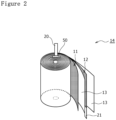
- FIG. 2 is a perspective view of an electrode assembly 14 of the cylindrical battery 10.
- the cylindrical battery 10 comprises a wound-type electrode assembly 14, a non-aqueous electrolyte (not illustrated), and a bottomed cylindrical metal exterior housing can 16 that houses the electrode assembly 14 and the non-aqueous electrolyte, and a sealing assembly 17 with which an opening of the exterior housing can 16 is capped.
- the electrode assembly 14 has a wound structure in which an elongated positive electrode 11 and an elongated negative electrode 12 are wound with two elongated separators 13 each interposed between the positive electrode 11 and the negative electrode 12.
- the negative electrode 12 is formed to be one size larger than the positive electrode 11 in order to prevent precipitation of lithium. That is, the negative electrode 12 is formed to be longer in the longitudinal direction and the width direction (short direction) than the positive electrode 11.
- the two separators 13 are each formed to be at least one size larger than the positive electrode 11, and are disposed so as to interpose, for example, the positive electrode 11 therebetween.
- the negative electrode 12 may include a winding start end of the electrode assembly 14. However, the separator 13 generally extends beyond a winding start side end of the negative electrode 12, and a winding start side end of the separator 13 serves as the winding start end of the electrode assembly 14.
- the non-aqueous electrolyte includes a non-aqueous solvent, and an electrolyte salt dissolved in the non-aqueous solvent.
- the non-aqueous solvent may include esters, ethers, nitriles, amides, and mixed solvents containing two or more selected from the foregoing.
- the non-aqueous solvent may contain a halogen-substituted product obtained by substituting at least some of hydrogen atoms in these solvents with a halogen atom such as fluorine.
- the non-aqueous electrolyte is not limited to a liquid electrolyte and may be a solid electrolyte that uses a gel polymer or the like.
- the electrolyte salt a lithium salt such as LiPF 6 is used.
- the positive electrode 11 has a positive electrode current collector 61 (see FIG. 3 ) and a positive electrode mixture layer 62 (see FIG. 3 ) formed on each surface of the positive electrode current collector.
- the positive electrode current collector 61 may include a foil of metal such as aluminum or an aluminum alloy, which is stable within a potential range of the positive electrode 11, and a film in which such a metal is disposed on a surface layer thereof.
- the positive electrode mixture layer 62 includes a positive electrode active material, a conductive agent, and a binder.
- the positive electrode 11 can be produced by, for example, applying a positive electrode mixture slurry including a positive electrode active material, a conductive agent, a binder, and the like on a positive electrode current collector 61, drying the resulting coating film, and then compressing the coating film to form a positive electrode mixture layer on each surface of the current collector.
- the positive electrode active material is composed of a lithium-containing metal composite oxide as a main component.
- metal elements contained in the lithium-containing metal composite oxide include Ni, Co, Mn, Al, B, Mg, Ti, V, Cr, Fe, Cu, Zn, Ga, Sr, Zr, Nb, In, Sn, Ta, and W.
- An example of a preferable lithium-containing metal composite oxide is a composite oxide containing at least one of Ni, Co, Mn and Al.
- Examples of the conductive agent included in the positive electrode mixture layer 62 may include carbon materials such as carbon black, acetylene black, Ketjen black, and graphite.
- Examples of the binder included in the positive electrode mixture layer may include fluorocarbon resins such as polytetrafluoroethylene (PTFE) and polyvinylidene fluoride (PVdF), polyacrylonitrile (PAN), polyimide resins, acrylic resins, and polyolefin resins. These resins may be used in combination with cellulose derivatives such as carboxymethyl cellulose (CMC) or a salt thereof, a polyethylene oxide (PEO), or the like.
- CMC carboxymethyl cellulose
- PEO polyethylene oxide
- the negative electrode 12 has a negative electrode current collector and a negative electrode mixture layer formed on each surface of the negative electrode current collector.
- the negative electrode current collector may include a foil of a metal such as copper or a copper alloy, which is stable within a potential range of the negative electrode 12, and a film in which such a metal is disposed on a surface layer thereof.
- the negative electrode mixture layer includes a negative electrode active material, and a binder.
- the negative electrode 12 can be produced by, for example, applying a negative electrode mixture slurry including a negative electrode active material, a binder, and the like on a negative electrode current collector, drying the resulting coating film, and then compressing the coating film to form a negative electrode mixture layer on each surface of the current collector.
- the negative electrode active material a carbon material that reversibly occludes and releases lithium ions is generally used.
- a preferable carbon material is graphite including natural graphite such as flaky graphite, massive graphite, and earthy graphite, and artificial graphite such as massive artificial graphite and graphitized mesophase carbon microbeads.
- a silicon (Si) material containing Si may be included in the negative electrode mixture layer.
- a metal alloyed with lithium other than Si an alloy containing such a metal, a compound containing such a metal, and the like may be used.
- fluorocarbon resins PAN, polyimide resins, acrylic resins, polyolefin resins, and the like may be used as in the case of the positive electrode 11, and a styrene-butadiene rubber (SBR) or a modification thereof is preferably used.
- SBR styrene-butadiene rubber
- CMC CMC or a salt thereof
- PAA polyacrylic acid
- polyvinyl alcohol or the like
- a porous sheet having ion permeability and an insulation property is used as the separator 13.
- the porous sheet include a microporous thin film, a woven fabric, and a nonwoven fabric.
- the material of the separator 13 is preferably a polyolefin resin such as polyethylene or polypropylene, or a cellulose.
- the separator 13 may be either a single layer structure or a laminated structure.
- a heat-resistant layer or the like may be formed on a surface of the separator 13.
- a positive electrode lead 20 is bonded to the positive electrode 11, and a negative electrode lead 21 is bonded on a winding finish-side in the longitudinal direction of the negative electrode 12.
- the cylindrical battery 10 has an insulating plate 18 above the electrode assembly 14, and has an insulating plate 19 below the electrode assembly 14.
- the positive electrode lead 20 extends toward the sealing assembly 17 through a through hole of the insulating plate 18, and the negative electrode lead 21 extends toward a bottom 68 of the exterior housing can 16 through the outside of the insulating plate 19.
- the positive electrode lead 20 is connected to a lower surface of a bottom plate 23 of the sealing assembly 17, by means of welding or the like.
- a terminal cap 27 constituting a top plate of the sealing assembly 17 is electrically connected to the bottom plate 23, and serves as a positive electrode terminal.
- the negative electrode lead 21 is connected to an inner surface of the bottom 68 of the metal exterior housing can 16 by means of welding or the like, and the exterior housing can 16 serves as a negative electrode terminal.
- the positive electrode lead 20 is electrically connected to an intermediate portion such as a center portion in the winding direction of the positive electrode current collector, and the negative electrode lead 21 is electrically connected to a winding finish-side end in the winding direction of the negative electrode current collector.
- the negative electrode lead may be electrically connected to a winding start-side end in the winding direction of the negative electrode current collector.
- the electrode assembly may have two negative electrode leads in which one of the negative electrode leads is electrically connected to the winding start side-end in the winding direction of the negative electrode current collector, and the other negative electrode lead is electrically connected to the winding finish-side end in the winding direction of the negative electrode current collector.
- the winding finish-side end in the winding direction of the negative electrode current collector may be brought into contact with an inner surface of the exterior housing can so that the negative electrode and the exterior housing can are electrically connected to each other.
- the cylindrical battery 10 further comprises a resin gasket 28 disposed between the exterior housing can 16 and the sealing assembly 17.
- the sealing assembly 17 is fixed by caulking to the opening of the exterior housing can 16 with the gasket 28 interposed therebetween. In this way, an internal space of the cylindrical battery 10 is closed.
- the gasket 28 is held between the exterior housing can 16 and the sealing assembly 17, and insulates the sealing assembly 17 from the exterior housing can 16.
- the gasket 28 has a role of a seal material for maintaining the airtightness of the inside of the battery, and a role as an insulating material for insulating the sealing assembly 17 from the exterior housing can 16.
- the exterior housing can 16 houses the electrode assembly 14 and the non-aqueous electrolyte, and has a shoulder 38, a grooved portion 34, a cylindrical portion 30, and a bottom 68.
- the grooved portion 34 can be formed by, for example, annularly recessing the one part of the side surface of the exterior housing can 16 toward the radially inward side by a radially inward spinning process.
- the shoulder 38 is formed by bending an upper end of the exterior housing can 16 to the inner side toward a circumferential edge 45 of the sealing assembly 17 when the sealing assembly 17 is fixed by caulking to the exterior housing can 16.
- the sealing assembly 17 has a stacked structure of the bottom plate 23, a lower vent member 24, an insulating member 25, an upper vent member 26, and the terminal cap 27 in this order from the electrode assembly 14 side.
- Each member constituting the sealing assembly 17 has, for example, a disk shape or a ring shape, and each member except for the insulating member 25 is electrically connected to each other.
- the bottom plate 23 has at least one through hole 23a.
- the lower vent member 24 and the upper vent member 26 are connected to each other at respective centers thereof, and the insulating member 25 is interposed between the circumferential edges of the vent members 24 and 26.
- the lower vent member 24 is deformed so as to push the upper vent member 26 upward to the terminal cap 27 side to break, resulting in cutting off of a current path between the lower vent member 24 and the upper vent member 26. If the internal pressure further increases, the upper vent member 26 breaks, and gas is discharged from a through hole 27a in the terminal cap 27. This gas discharge can prevent the cylindrical battery 10 from rupturing due to an excessive increase in internal pressure of the cylindrical battery 10, which makes it possible to improve the safety of the cylindrical battery 10.
- FIG. 3 is an enlarged schematic radial sectional view around a bonding portion of the positive electrode lead 20 in the electrode assembly 14.
- the positive electrode lead 20 is bonded to an exposed portion of the positive electrode current collector 61, and the positive electrode lead 20 and the positive electrode mixture layer 62 near the positive electrode lead 20 are covered by an insulating tape 50 to prevent a short circuit.
- the thickness of the positive electrode lead 20 is larger than the thickness of the positive electrode mixture layer 62.
- the insulating tape 50 is disposed to cover the positive electrode lead 20 and the positive electrode mixture layer 62, and the thickness of a first facing portion 71 in the insulating tape 50 that faces the positive electrode lead 20 is smaller than the thickness of a second facing portion 72 in the insulating tape 50 that faces the positive electrode mixture layer 62.
- the insulating tape 50 has a base layer 81 and a glue layer 82 partially provided to stick the insulating tape 50.
- the glue layer 82 is provided on the positive electrode mixture layer 62 side of the base layer 81 in the second facing portion 72, whereas the first facing portion 71 has no glue layer 82.
- the first facing portion 71 is thinner than the second facing portion 72 by the thickness of the glue layer 82.
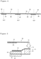
- FIG. 4 is a diagram illustrating an example of a method of producing the insulating tape 50.
- a conventional insulating tape is generally produced by applying glue to the entire surface on one side of the base material and then slitting predetermined portions.
- the insulating tape 50 of the present disclosure is produced by applying glue to a base material 91 so that non-applied portions 86 in which glue is not applied and applied portions 87 in which glue is applied are alternately arranged periodically with a certain interval as illustrated in FIG. 4 . Then, the insulating tape 50 is produced by slitting a center of each applied portion 87 on a plane including the thickness direction and the width direction of the base material 91.
- FIG. 5 is a diagram illustrating a method of sticking the produced insulating tape 50.
- the glue layer 82 formed by applying the glue on each side end of the second facing portion 72 is caused to face the positive electrode mixture layer 62, and the first facing portion 71 in which the glue is not applied at the center of the insulating tape 50 is caused to face the positive electrode lead 20.
- the insulating tape 50 is stuck to the positive electrode 11 by sticking the glue layer 82 of the second facing portion 72 to the positive electrode mixture layer 62.
- FIG. 6 is an enlarged schematic sectional view in a conventional cylindrical battery 110, corresponding to FIG. 3
- FIG. 7 is a diagram illustrating a method of sticking an insulating tape 150 in the conventional cylindrical battery 110, corresponding to FIG. 5 .
- glue 192 is applied to the entire surface of one surface of a base material 191 with a uniform thickness, and the insulating tape 150 has a uniform thickness. Accordingly, in one side surface of the positive electrode current collector 61 to which the positive electrode lead 20 is bonded, a difference (a dimension indicated by C in FIG.
- a portion proximate to the positive electrode lead in an electrode assembly 114 projects largely in the thickness direction of a positive electrode 111.
- a step in which the thickness varies largely is formed between the first facing portion 171 and the exposed portion of the positive electrode mixture layer 62. Therefore, the surface pressure around the positive electrode lead 20 becomes excessive, and thus stress concentration is generated around the positive electrode lead 20, which may cause local distortion. In this case, the reactions at the positive and negative electrodes during charging or discharging are nonuniform, resulting in the degradation of the cycling characteristic.
- the glue layer 82 is not provided on the first facing portion 71 so that the thickness of the first facing portion 71 is smaller than the thickness of the second facing portion 72.
- the thickness of the base layer 81 of the first facing portion 71 may be smaller than the thickness of the base layer 81 of the second facing portion 72 so that the thickness of the first facing portion 71 is smaller than the thickness of the second facing portion 72.
- the glue layer 82 may be provided on the entire surface of the base layer 81.
- the insulating tape 50 is disposed to cover the positive electrode lead 20 and the positive electrode mixture layer 62.
- the present disclosure can be also applied to a case where the insulating tape 50 is stuck to cover the negative electrode lead and the negative electrode mixture layer. This can prevent a large surface pressure from being locally generated around the negative electrode lead, and can prevent a cycling characteristic from being degraded.
- the insulating tape is disposed to cover the negative electrode lead and the negative electrode mixture layer, and the thickness of the first facing portion in the insulating tape that faces the negative electrode lead may be smaller than the thickness of a second facing portion in the insulating tape that faces the negative electrode mixture layer.
- the second facing portion has a glue layer for sticking the insulating tape, and the first facing portion may have no glue layer.
Landscapes
- Chemical & Material Sciences (AREA)
- Chemical Kinetics & Catalysis (AREA)
- Electrochemistry (AREA)
- General Chemical & Material Sciences (AREA)
- Engineering & Computer Science (AREA)
- Manufacturing & Machinery (AREA)
- Connection Of Batteries Or Terminals (AREA)
- Secondary Cells (AREA)
Abstract
Description
- The present disclosure generally relates to a cylindrical battery.
- Among conventional cylindrical batteries, there is a cylindrical battery disclosed in PATENT LITERATURE 1. This cylindrical battery comprises a bottomed cylindrical exterior housing can, an electrode assembly that is housed in the exterior housing can and in which an elongated positive electrode and an elongated negative electrode are wound with a separator interposed between the positive electrode and the negative electrode, and a positive electrode lead welded to the positive electrode. In this cylindrical battery, a thickness of a welding portion of a positive electrode lead plate is set within 1.25 times the thickness of a portion other than the welding portion, thereby suppressing winding misalignment in the welding portion of the positive electrode lead plate when a thickness of a positive electrode mixture layer is smaller than the thickness of the welding portion of the positive electrode lead.
- PATENT LITERATURE 1:
Japanese Unexamined Patent Application Publication No. Hei03-187155 - In order to reduce the electric resistance, and the like, the thickness of the positive electrode lead may be larger than the thickness of the positive electrode mixture layer around the positive electrode lead. In such a case, the positive electrode lead projects in a thickness direction of the positive electrode, and thus stress concentration is generated around the positive electrode lead, which may cause local distortion. In this case, due to the local distortion, the reactions at the positive and negative electrodes during charging or discharging are nonuniform, resulting in the degradation of the cycling characteristic.
- It is an advantage of the present disclosure to provide a cylindrical battery which can relieve stress concentration generated around an electrode lead and suppress the degradation of a cycling characteristic when the thickness of the electrode lead is larger than the thickness of a mixture layer.
- In order to solve the above-described problem, a cylindrical battery according to an aspect of the present disclosure comprises an electrode assembly in which an elongated positive electrode having a positive electrode current collector and a positive electrode mixture layer and an elongated negative electrode having a negative electrode current collector and a negative electrode mixture layer are wound with a separator interposed between the positive electrode and the negative electrode, a bottomed cylindrical exterior housing can that houses the electrode assembly, a positive electrode lead connected to an exposed portion of the positive electrode current collector, and an insulating tape, wherein the positive electrode mixture layer is provided on one side surface of the positive electrode current collector to which at least the positive electrode lead is connected, a thickness of the positive electrode mixture layer is smaller than a thickness of the positive electrode lead, the insulating tape is disposed to cover the positive electrode lead and the positive electrode mixture layer, and a thickness of a first facing portion in the insulating tape that faces the positive electrode lead is smaller than a thickness of a second facing portion in the insulating tape that faces the positive electrode mixture layer.
- A cylindrical battery according to another aspect of the present disclosure comprises an electrode assembly in which an elongated positive electrode having a positive electrode current collector and a positive electrode mixture layer and an elongated negative electrode having a negative electrode current collector and a negative electrode mixture layer are wound with a separator interposed between the positive electrode and the negative electrode, a bottomed cylindrical exterior housing can that houses the electrode assembly, a negative electrode lead connected to an exposed portion of the negative electrode current collector, and an insulating tape, wherein the negative electrode mixture layer is provided on one side surface of the negative electrode current collector to which at least the negative electrode lead is connected, a thickness of the negative electrode mixture layer is smaller than a thickness of the negative electrode lead, the insulating tape is disposed to cover the negative electrode lead and the negative electrode mixture layer, and a thickness of a first facing portion in the insulating tape that faces the negative electrode lead is smaller than a thickness of a second facing portion in the insulating tape that faces the negative electrode mixture layer.
- In the cylindrical battery according to the present disclosure, the stress concentration generated around an electrode lead can be relieved and the degradation of a cycling characteristic can be suppressed even when the thickness of the electrode lead is larger than the thickness of a mixture layer.
-
-
FIG. 1 is an axial sectional view of a cylindrical battery according to an embodiment of the present disclosure. -
FIG. 2 is a perspective view of an electrode assembly of the above-described cylindrical battery. -
FIG. 3 is an enlarged schematic radial sectional view around a bonding portion of a positive electrode lead in the above-described electrode assembly. -
FIG. 4 is a diagram illustrating an example of a method of producing an insulating tape of the present disclosure. -
FIG. 5 is a diagram illustrating a method of sticking the above-described insulating tape. -
FIG. 6 is an enlarged schematic sectional view in the conventional cylindrical battery, corresponding toFIG. 3 . -
FIG. 7 is a diagram illustrating a method of sticking an insulating tape in the conventional cylindrical battery, corresponding toFIG. 5 . - Hereinafter, an embodiment of a cylindrical battery according to the present disclosure will be described in detail with reference to the drawings. The cylindrical battery of the present disclosure may be a primary battery, or may be a secondary battery. Additionally, the cylindrical battery may be a battery using an aqueous electrolyte, or may be a battery using a non-aqueous electrolyte. In the following, a non-aqueous electrolyte secondary battery (lithium ion battery) using a non-aqueous electrolyte will be exemplified as a
cylindrical battery 10 of an embodiment, but the cylindrical battery of the present disclosure is not limited to this. - It is assumed from the beginning that a new embodiment is constructed by appropriately combining feature portions of embodiments and modifications which are described below. In the following embodiments, the same components are denoted by the same reference numerals in the drawings, and duplicate descriptions are omitted. Schematic diagrams are included in a plurality of the drawings, and the dimensional ratios such as lengths, widths and heights of each member between different drawings are not necessarily the same. In this specification, a
sealing assembly 17 side in an axial direction (height direction) of acylindrical battery 10 is defined as "upper", and abottom 68 side of an exterior housing can 16 in the axial direction is defined as "lower". Additionally, of the components described below, components that are not described in the independent claim indicating the highest level concept are arbitrary components, and are not essential components. -
FIG. 1 is an axial sectional view of thecylindrical battery 10 according to an embodiment of the present disclosure, andFIG. 2 is a perspective view of anelectrode assembly 14 of thecylindrical battery 10. As illustrated inFIG. 1 , thecylindrical battery 10 comprises a wound-type electrode assembly 14, a non-aqueous electrolyte (not illustrated), and a bottomed cylindrical metal exterior housing can 16 that houses theelectrode assembly 14 and the non-aqueous electrolyte, and asealing assembly 17 with which an opening of the exterior housing can 16 is capped. As illustrated inFIG. 2 , theelectrode assembly 14 has a wound structure in which an elongatedpositive electrode 11 and an elongatednegative electrode 12 are wound with twoelongated separators 13 each interposed between thepositive electrode 11 and thenegative electrode 12. - The
negative electrode 12 is formed to be one size larger than thepositive electrode 11 in order to prevent precipitation of lithium. That is, thenegative electrode 12 is formed to be longer in the longitudinal direction and the width direction (short direction) than thepositive electrode 11. The twoseparators 13 are each formed to be at least one size larger than thepositive electrode 11, and are disposed so as to interpose, for example, thepositive electrode 11 therebetween. Thenegative electrode 12 may include a winding start end of theelectrode assembly 14. However, theseparator 13 generally extends beyond a winding start side end of thenegative electrode 12, and a winding start side end of theseparator 13 serves as the winding start end of theelectrode assembly 14. - The non-aqueous electrolyte includes a non-aqueous solvent, and an electrolyte salt dissolved in the non-aqueous solvent. Examples of the non-aqueous solvent may include esters, ethers, nitriles, amides, and mixed solvents containing two or more selected from the foregoing. The non-aqueous solvent may contain a halogen-substituted product obtained by substituting at least some of hydrogen atoms in these solvents with a halogen atom such as fluorine. Note that the non-aqueous electrolyte is not limited to a liquid electrolyte and may be a solid electrolyte that uses a gel polymer or the like. As the electrolyte salt, a lithium salt such as LiPF6 is used.
- The
positive electrode 11 has a positive electrode current collector 61 (seeFIG. 3 ) and a positive electrode mixture layer 62 (seeFIG. 3 ) formed on each surface of the positive electrode current collector. Examples of the positive electrodecurrent collector 61 may include a foil of metal such as aluminum or an aluminum alloy, which is stable within a potential range of thepositive electrode 11, and a film in which such a metal is disposed on a surface layer thereof. The positiveelectrode mixture layer 62 includes a positive electrode active material, a conductive agent, and a binder. Thepositive electrode 11 can be produced by, for example, applying a positive electrode mixture slurry including a positive electrode active material, a conductive agent, a binder, and the like on a positiveelectrode current collector 61, drying the resulting coating film, and then compressing the coating film to form a positive electrode mixture layer on each surface of the current collector. - The positive electrode active material is composed of a lithium-containing metal composite oxide as a main component. Examples of metal elements contained in the lithium-containing metal composite oxide include Ni, Co, Mn, Al, B, Mg, Ti, V, Cr, Fe, Cu, Zn, Ga, Sr, Zr, Nb, In, Sn, Ta, and W. An example of a preferable lithium-containing metal composite oxide is a composite oxide containing at least one of Ni, Co, Mn and Al.
- Examples of the conductive agent included in the positive
electrode mixture layer 62 may include carbon materials such as carbon black, acetylene black, Ketjen black, and graphite. Examples of the binder included in the positive electrode mixture layer may include fluorocarbon resins such as polytetrafluoroethylene (PTFE) and polyvinylidene fluoride (PVdF), polyacrylonitrile (PAN), polyimide resins, acrylic resins, and polyolefin resins. These resins may be used in combination with cellulose derivatives such as carboxymethyl cellulose (CMC) or a salt thereof, a polyethylene oxide (PEO), or the like. - The
negative electrode 12 has a negative electrode current collector and a negative electrode mixture layer formed on each surface of the negative electrode current collector. Examples of the negative electrode current collector may include a foil of a metal such as copper or a copper alloy, which is stable within a potential range of thenegative electrode 12, and a film in which such a metal is disposed on a surface layer thereof. The negative electrode mixture layer includes a negative electrode active material, and a binder. Thenegative electrode 12 can be produced by, for example, applying a negative electrode mixture slurry including a negative electrode active material, a binder, and the like on a negative electrode current collector, drying the resulting coating film, and then compressing the coating film to form a negative electrode mixture layer on each surface of the current collector. - As the negative electrode active material, a carbon material that reversibly occludes and releases lithium ions is generally used. A preferable carbon material is graphite including natural graphite such as flaky graphite, massive graphite, and earthy graphite, and artificial graphite such as massive artificial graphite and graphitized mesophase carbon microbeads. As the negative electrode active material, a silicon (Si) material containing Si may be included in the negative electrode mixture layer. As the negative electrode active material, a metal alloyed with lithium other than Si, an alloy containing such a metal, a compound containing such a metal, and the like may be used.
- As the binder included in the negative electrode mixture layer, fluorocarbon resins, PAN, polyimide resins, acrylic resins, polyolefin resins, and the like may be used as in the case of the
positive electrode 11, and a styrene-butadiene rubber (SBR) or a modification thereof is preferably used. In the negative electrode mixture layer, for example, in addition to SBR and the like, CMC or a salt thereof, polyacrylic acid (PAA) or a salt thereof, polyvinyl alcohol, or the like may be included. - A porous sheet having ion permeability and an insulation property is used as the
separator 13. Specific examples of the porous sheet include a microporous thin film, a woven fabric, and a nonwoven fabric. The material of theseparator 13 is preferably a polyolefin resin such as polyethylene or polypropylene, or a cellulose. Theseparator 13 may be either a single layer structure or a laminated structure. A heat-resistant layer or the like may be formed on a surface of theseparator 13. - As illustrated in
FIG. 1 , apositive electrode lead 20 is bonded to thepositive electrode 11, and anegative electrode lead 21 is bonded on a winding finish-side in the longitudinal direction of thenegative electrode 12. Thecylindrical battery 10 has an insulatingplate 18 above theelectrode assembly 14, and has an insulatingplate 19 below theelectrode assembly 14. Thepositive electrode lead 20 extends toward the sealingassembly 17 through a through hole of the insulatingplate 18, and thenegative electrode lead 21 extends toward a bottom 68 of the exterior housing can 16 through the outside of the insulatingplate 19. Thepositive electrode lead 20 is connected to a lower surface of abottom plate 23 of the sealingassembly 17, by means of welding or the like. Aterminal cap 27 constituting a top plate of the sealingassembly 17 is electrically connected to thebottom plate 23, and serves as a positive electrode terminal. Thenegative electrode lead 21 is connected to an inner surface of the bottom 68 of the metal exterior housing can 16 by means of welding or the like, and the exterior housing can 16 serves as a negative electrode terminal. - In the example illustrated in
FIGS. 1 and2 , thepositive electrode lead 20 is electrically connected to an intermediate portion such as a center portion in the winding direction of the positive electrode current collector, and thenegative electrode lead 21 is electrically connected to a winding finish-side end in the winding direction of the negative electrode current collector. However, the negative electrode lead may be electrically connected to a winding start-side end in the winding direction of the negative electrode current collector. Alternatively, the electrode assembly may have two negative electrode leads in which one of the negative electrode leads is electrically connected to the winding start side-end in the winding direction of the negative electrode current collector, and the other negative electrode lead is electrically connected to the winding finish-side end in the winding direction of the negative electrode current collector. Alternatively, the winding finish-side end in the winding direction of the negative electrode current collector may be brought into contact with an inner surface of the exterior housing can so that the negative electrode and the exterior housing can are electrically connected to each other. - The
cylindrical battery 10 further comprises aresin gasket 28 disposed between the exterior housing can 16 and the sealingassembly 17. The sealingassembly 17 is fixed by caulking to the opening of the exterior housing can 16 with thegasket 28 interposed therebetween. In this way, an internal space of thecylindrical battery 10 is closed. Thegasket 28 is held between the exterior housing can 16 and the sealingassembly 17, and insulates the sealingassembly 17 from the exterior housing can 16. Thegasket 28 has a role of a seal material for maintaining the airtightness of the inside of the battery, and a role as an insulating material for insulating the sealingassembly 17 from the exterior housing can 16. - The exterior housing can 16 houses the
electrode assembly 14 and the non-aqueous electrolyte, and has ashoulder 38, a grooved portion 34, acylindrical portion 30, and a bottom 68. The grooved portion 34 can be formed by, for example, annularly recessing the one part of the side surface of the exterior housing can 16 toward the radially inward side by a radially inward spinning process. Theshoulder 38 is formed by bending an upper end of the exterior housing can 16 to the inner side toward acircumferential edge 45 of the sealingassembly 17 when the sealingassembly 17 is fixed by caulking to the exterior housing can 16. - The sealing
assembly 17 has a stacked structure of thebottom plate 23, alower vent member 24, an insulatingmember 25, anupper vent member 26, and theterminal cap 27 in this order from theelectrode assembly 14 side. Each member constituting the sealingassembly 17 has, for example, a disk shape or a ring shape, and each member except for the insulatingmember 25 is electrically connected to each other. Thebottom plate 23 has at least one throughhole 23a. Thelower vent member 24 and theupper vent member 26 are connected to each other at respective centers thereof, and the insulatingmember 25 is interposed between the circumferential edges of thevent members - If abnormal heat generation occurs in the
cylindrical battery 10 and the internal pressure of thecylindrical battery 10 increases, thelower vent member 24 is deformed so as to push theupper vent member 26 upward to theterminal cap 27 side to break, resulting in cutting off of a current path between thelower vent member 24 and theupper vent member 26. If the internal pressure further increases, theupper vent member 26 breaks, and gas is discharged from a throughhole 27a in theterminal cap 27. This gas discharge can prevent thecylindrical battery 10 from rupturing due to an excessive increase in internal pressure of thecylindrical battery 10, which makes it possible to improve the safety of thecylindrical battery 10. -
FIG. 3 is an enlarged schematic radial sectional view around a bonding portion of thepositive electrode lead 20 in theelectrode assembly 14. As illustrated inFIG. 3 , thepositive electrode lead 20 is bonded to an exposed portion of the positive electrodecurrent collector 61, and thepositive electrode lead 20 and the positiveelectrode mixture layer 62 near thepositive electrode lead 20 are covered by an insulatingtape 50 to prevent a short circuit. The thickness of thepositive electrode lead 20 is larger than the thickness of the positiveelectrode mixture layer 62. The insulatingtape 50 is disposed to cover thepositive electrode lead 20 and the positiveelectrode mixture layer 62, and the thickness of a first facingportion 71 in the insulatingtape 50 that faces thepositive electrode lead 20 is smaller than the thickness of a second facingportion 72 in the insulatingtape 50 that faces the positiveelectrode mixture layer 62. - The insulating
tape 50 has abase layer 81 and aglue layer 82 partially provided to stick the insulatingtape 50. Theglue layer 82 is provided on the positiveelectrode mixture layer 62 side of thebase layer 81 in the second facingportion 72, whereas the first facingportion 71 has noglue layer 82. As a result, the first facingportion 71 is thinner than the second facingportion 72 by the thickness of theglue layer 82. In one side surface of the positive electrodecurrent collector 61 to which thepositive electrode lead 20 is bonded, a difference (a dimension indicated by A inFIG. 3 ) between the thickness of a portion including the first facingportion 71 and thepositive electrode lead 20 and the thickness of a portion including the second facingportion 72 and the positiveelectrode mixture layer 62 is preferably equal to the thickness of the second facing portion 72 (a dimension indicated by B inFIG. 3 ). This can not only reduce the thickness of the portion including the first facingportion 71 and thepositive electrode lead 20 but also equalize variations in the thickness of a step between the first facingportion 71 and the exposed portion of the positiveelectrode mixture layer 62. In this way, if A,:t B is established, a large surface pressure can be significantly prevented from being locally generated around thepositive electrode lead 20 and a cycling characteristic can be significantly prevented from being degraded. Note that if 0.5 ≤ A/B ≤ 1.5 is established, a large surface pressure can be effectively prevented from being locally generated around thepositive electrode lead 20 and a cycling characteristic can be effectively prevented from being degraded. -
FIG. 4 is a diagram illustrating an example of a method of producing the insulatingtape 50. A conventional insulating tape is generally produced by applying glue to the entire surface on one side of the base material and then slitting predetermined portions. However, the insulatingtape 50 of the present disclosure is produced by applying glue to abase material 91 so thatnon-applied portions 86 in which glue is not applied and appliedportions 87 in which glue is applied are alternately arranged periodically with a certain interval as illustrated inFIG. 4 . Then, the insulatingtape 50 is produced by slitting a center of each appliedportion 87 on a plane including the thickness direction and the width direction of thebase material 91. -
FIG. 5 is a diagram illustrating a method of sticking the produced insulatingtape 50. As illustrated inFIG. 5 , theglue layer 82 formed by applying the glue on each side end of the second facingportion 72 is caused to face the positiveelectrode mixture layer 62, and the first facingportion 71 in which the glue is not applied at the center of the insulatingtape 50 is caused to face thepositive electrode lead 20. Then, the insulatingtape 50 is stuck to thepositive electrode 11 by sticking theglue layer 82 of the second facingportion 72 to the positiveelectrode mixture layer 62. -
FIG. 6 is an enlarged schematic sectional view in a conventionalcylindrical battery 110, corresponding toFIG. 3 , andFIG. 7 is a diagram illustrating a method of sticking an insulatingtape 150 in the conventionalcylindrical battery 110, corresponding toFIG. 5 . As illustrated inFIGS. 6 and 7 , in the conventionalcylindrical battery 110,glue 192 is applied to the entire surface of one surface of abase material 191 with a uniform thickness, and the insulatingtape 150 has a uniform thickness. Accordingly, in one side surface of the positive electrodecurrent collector 61 to which thepositive electrode lead 20 is bonded, a difference (a dimension indicated by C inFIG. 3 ) between the thickness of a portion including a first facingportion 171 and apositive electrode lead 20 and the thickness of a portion including a second facingportion 172 and a positiveelectrode mixture layer 62 is larger than the thickness of the second facing portion 172 (a dimension indicated by D inFIG. 3 ). In this way, in the conventionalcylindrical battery 110, the thickness of the portion including the first facingportion 171 and thepositive electrode lead 20 is increased, and further, it is required to reduce the thickness of thepositive electrode lead 20 to establish C « D, which makes it difficult to reduce an electric resistance of thepositive electrode lead 20. - When the positive electrode and the negative electrode are wound without reducing the thickness of the positive electrode lead, a portion proximate to the positive electrode lead in an
electrode assembly 114 projects largely in the thickness direction of a positive electrode 111. A step in which the thickness varies largely is formed between the first facingportion 171 and the exposed portion of the positiveelectrode mixture layer 62. Therefore, the surface pressure around thepositive electrode lead 20 becomes excessive, and thus stress concentration is generated around thepositive electrode lead 20, which may cause local distortion. In this case, the reactions at the positive and negative electrodes during charging or discharging are nonuniform, resulting in the degradation of the cycling characteristic. - The present disclosure is not limited to the above embodiment and modified examples thereof, and various improvements and changes are possible within the matters described in the claims of the present application and the scope of equivalence of claims.
- For example, in the above embodiment, the
glue layer 82 is not provided on the first facingportion 71 so that the thickness of the first facingportion 71 is smaller than the thickness of the second facingportion 72. Alternatively, the thickness of thebase layer 81 of the first facingportion 71 may be smaller than the thickness of thebase layer 81 of the second facingportion 72 so that the thickness of the first facingportion 71 is smaller than the thickness of the second facingportion 72. In this case, theglue layer 82 may be provided on the entire surface of thebase layer 81. - In the above embodiment, there has been described a case where the insulating
tape 50 is disposed to cover thepositive electrode lead 20 and the positiveelectrode mixture layer 62. However, the present disclosure can be also applied to a case where the insulatingtape 50 is stuck to cover the negative electrode lead and the negative electrode mixture layer. This can prevent a large surface pressure from being locally generated around the negative electrode lead, and can prevent a cycling characteristic from being degraded. - Specifically, the insulating tape is disposed to cover the negative electrode lead and the negative electrode mixture layer, and the thickness of the first facing portion in the insulating tape that faces the negative electrode lead may be smaller than the thickness of a second facing portion in the insulating tape that faces the negative electrode mixture layer. In this case, the second facing portion has a glue layer for sticking the insulating tape, and the first facing portion may have no glue layer.
- 10 Cylindrical battery, 11 Positive electrode, 12 Negative electrode, 13 Separator, 14 Electrode assembly, 16 Exterior housing can, 17 Sealing assembly, 18, 19 Insulating plate, 20 Positive electrode lead, 21 Negative electrode lead, 23 Bottom plate, 23a Through hole, 24 Lower vent member, 25 Insulating member, 26 Upper vent member, 27 Terminal cap, 27a Through hole, 28 Gasket, 30 Cylindrical portion, 34 Grooved portion, 38 Shoulder, 45 Circumferential edge, 50 Insulating tape, 61 Positive electrode current collector, 62 Positive electrode mixture layer, 68 Bottom, 71 First facing portion, 72 Second facing portion, 81 Base layer, 82 Glue layer, 86 Non-applied portion, 87 Applied portion, 91 Base material
Claims (4)
- A cylindrical battery, comprising:an electrode assembly in which an elongated positive electrode having a positive electrode current collector and a positive electrode mixture layer and an elongated negative electrode having a negative electrode current collector and a negative electrode mixture layer are wound with a separator interposed between the positive electrode and the negative electrode;a bottomed cylindrical exterior housing can that houses the electrode assembly;a positive electrode lead connected to an exposed portion of the positive electrode current collector; andan insulating tape,wherein the positive electrode mixture layer is provided on one side surface of the positive electrode current collector to which at least the positive electrode lead is connected,a thickness of the positive electrode mixture layer is smaller than a thickness of the positive electrode lead,the insulating tape is disposed to cover the positive electrode lead and the positive electrode mixture layer, anda thickness of a first facing portion in the insulating tape that faces the positive electrode lead is smaller than a thickness of a second facing portion in the insulating tape that faces the positive electrode mixture layer.
- The cylindrical battery according to claim 1, whereinthe insulating tape has a base layer and a glue layer, andthe second facing portion has the glue layer on the positive electrode mixture layer side of the base layer, and the first facing portion does not have the glue layer.
- A cylindrical battery, comprising:an electrode assembly in which an elongated positive electrode having a positive electrode current collector and a positive electrode mixture layer and an elongated negative electrode having a negative electrode current collector and a negative electrode mixture layer are wound with a separator interposed between the positive electrode and the negative electrode;a bottomed cylindrical exterior housing can that houses the electrode assembly;a negative electrode lead bonded to an exposed portion of the negative electrode current collector; andan insulating tape,wherein the negative electrode mixture layer is provided on one side surface of the negative electrode current collector to which at least the negative electrode lead is bonded,a thickness of the negative electrode mixture layer is smaller than a thickness of the negative electrode lead,the insulating tape is disposed to cover the negative electrode lead and the negative electrode mixture layer, anda thickness of a first facing portion in the insulating tape that faces the negative electrode lead is smaller than a thickness of a second facing portion in the insulating tape that faces the negative electrode mixture layer.
- The cylindrical battery according to claim 3, whereinthe insulating tape has a base layer and a glue layer, andthe second facing portion has the glue layer on the negative electrode mixture layer side of the base layer, and the first facing portion does not have the glue layer.
Applications Claiming Priority (2)
| Application Number | Priority Date | Filing Date | Title |
|---|---|---|---|
| JP2021160882 | 2021-09-30 | ||
| PCT/JP2022/034679 WO2023054005A1 (en) | 2021-09-30 | 2022-09-16 | Cylindrical battery |
Publications (2)
| Publication Number | Publication Date |
|---|---|
| EP4411979A1 true EP4411979A1 (en) | 2024-08-07 |
| EP4411979A4 EP4411979A4 (en) | 2025-04-30 |
Family
ID=85782500
Family Applications (1)
| Application Number | Title | Priority Date | Filing Date |
|---|---|---|---|
| EP22875876.9A Pending EP4411979A4 (en) | 2021-09-30 | 2022-09-16 | CYLINDRICAL BATTERY |
Country Status (5)
| Country | Link |
|---|---|
| US (1) | US20240387966A1 (en) |
| EP (1) | EP4411979A4 (en) |
| JP (1) | JPWO2023054005A1 (en) |
| CN (1) | CN117981165A (en) |
| WO (1) | WO2023054005A1 (en) |
Cited By (1)
| Publication number | Priority date | Publication date | Assignee | Title |
|---|---|---|---|---|
| EP4525128A1 (en) * | 2023-09-12 | 2025-03-19 | Samsung Sdi Co., Ltd. | Secondary battery and method of forming the same |
Families Citing this family (1)
| Publication number | Priority date | Publication date | Assignee | Title |
|---|---|---|---|---|
| KR20250177768A (en) * | 2024-06-17 | 2025-12-24 | 삼성에스디아이 주식회사 | Secondary battery electrode where tape is attached and electrode assemblly including the same |
Family Cites Families (4)
| Publication number | Priority date | Publication date | Assignee | Title |
|---|---|---|---|---|
| JPH03187155A (en) | 1989-12-15 | 1991-08-15 | Fuji Elelctrochem Co Ltd | Spiral-type nonaqueous electrolyte battery |
| JP7122581B2 (en) * | 2017-12-25 | 2022-08-22 | パナソニックIpマネジメント株式会社 | secondary battery |
| EP3872894A4 (en) * | 2018-10-23 | 2021-12-15 | Panasonic Intellectual Property Management Co., Ltd. | Battery and protective tape for batteries |
| JP7320166B2 (en) * | 2019-03-14 | 2023-08-03 | パナソニックエナジー株式会社 | secondary battery |
-
2022
- 2022-09-16 WO PCT/JP2022/034679 patent/WO2023054005A1/en not_active Ceased
- 2022-09-16 US US18/690,796 patent/US20240387966A1/en active Pending
- 2022-09-16 CN CN202280062041.6A patent/CN117981165A/en active Pending
- 2022-09-16 JP JP2023551318A patent/JPWO2023054005A1/ja active Pending
- 2022-09-16 EP EP22875876.9A patent/EP4411979A4/en active Pending
Cited By (1)
| Publication number | Priority date | Publication date | Assignee | Title |
|---|---|---|---|---|
| EP4525128A1 (en) * | 2023-09-12 | 2025-03-19 | Samsung Sdi Co., Ltd. | Secondary battery and method of forming the same |
Also Published As
| Publication number | Publication date |
|---|---|
| US20240387966A1 (en) | 2024-11-21 |
| JPWO2023054005A1 (en) | 2023-04-06 |
| CN117981165A (en) | 2024-05-03 |
| EP4411979A4 (en) | 2025-04-30 |
| WO2023054005A1 (en) | 2023-04-06 |
Similar Documents
| Publication | Publication Date | Title |
|---|---|---|
| EP4432433A1 (en) | Cylindrical battery | |
| KR101224528B1 (en) | Lithium-ion secondary battery | |
| JP2011187337A (en) | Cylindrical battery cell with non-aqueous electrolyte | |
| US20250158243A1 (en) | Battery and current collector | |
| EP4471975A1 (en) | Nonaqueous electrolyte secondary battery | |
| US20240178522A1 (en) | Cylindrical battery | |
| EP4411979A1 (en) | Cylindrical battery | |
| US20240055719A1 (en) | Sealed battery | |
| EP4489211A1 (en) | Cylindrical nonaqueous electrolyte secondary battery | |
| US20240313305A1 (en) | Cylindrical battery | |
| EP4350798A1 (en) | Non-aqueous electrolyte secondary battery | |
| US20240234977A9 (en) | Cylindrical battery | |
| US20230079288A1 (en) | Nonaqueous electrolyte secondary battery and electrode for nonaqueous electrolyte secondary batteries | |
| US20220302508A1 (en) | Non-aqueous electrolyte secondary battery and method for producing non-aqueous electrolyte secondary battery | |
| US20230073596A1 (en) | Non-aqueous electrolytic secondary battery | |
| US20250210763A1 (en) | Cylindrical battery | |
| US20250273834A1 (en) | Cylindrical battery | |
| US20250192294A1 (en) | Cylindrical battery | |
| EP4239764A1 (en) | Cylindrical battery | |
| EP4270613A1 (en) | Hermetically sealed battery | |
| US20250055159A1 (en) | Cylindrical battery | |
| EP4629406A1 (en) | Cylindrical battery | |
| US20250379301A1 (en) | Sealed battery | |
| US20250192293A1 (en) | Cylindrical battery | |
| US20250309422A1 (en) | Cylindrical battery |
Legal Events
| Date | Code | Title | Description |
|---|---|---|---|
| STAA | Information on the status of an ep patent application or granted ep patent |
Free format text: STATUS: THE INTERNATIONAL PUBLICATION HAS BEEN MADE |
|
| PUAI | Public reference made under article 153(3) epc to a published international application that has entered the european phase |
Free format text: ORIGINAL CODE: 0009012 |
|
| STAA | Information on the status of an ep patent application or granted ep patent |
Free format text: STATUS: REQUEST FOR EXAMINATION WAS MADE |
|
| 17P | Request for examination filed |
Effective date: 20240307 |
|
| AK | Designated contracting states |
Kind code of ref document: A1 Designated state(s): AL AT BE BG CH CY CZ DE DK EE ES FI FR GB GR HR HU IE IS IT LI LT LU LV MC MK MT NL NO PL PT RO RS SE SI SK SM TR |
|
| DAV | Request for validation of the european patent (deleted) | ||
| DAX | Request for extension of the european patent (deleted) | ||
| A4 | Supplementary search report drawn up and despatched |
Effective date: 20250331 |
|
| RIC1 | Information provided on ipc code assigned before grant |
Ipc: H01M 50/538 20210101ALI20250325BHEP Ipc: H01M 50/536 20210101ALI20250325BHEP Ipc: H01M 50/534 20210101ALI20250325BHEP Ipc: H01M 50/533 20210101ALI20250325BHEP Ipc: H01M 50/107 20210101ALI20250325BHEP Ipc: H01M 50/586 20210101ALI20250325BHEP Ipc: H01M 50/531 20210101ALI20250325BHEP Ipc: H01M 10/0587 20100101ALI20250325BHEP Ipc: H01M 10/04 20060101ALI20250325BHEP Ipc: H01M 50/595 20210101AFI20250325BHEP |