EP4411871A1 - Anode active material for lithium secondary battery and lithium secondary battery including the same - Google Patents
Anode active material for lithium secondary battery and lithium secondary battery including the same Download PDFInfo
- Publication number
- EP4411871A1 EP4411871A1 EP24153899.0A EP24153899A EP4411871A1 EP 4411871 A1 EP4411871 A1 EP 4411871A1 EP 24153899 A EP24153899 A EP 24153899A EP 4411871 A1 EP4411871 A1 EP 4411871A1
- Authority
- EP
- European Patent Office
- Prior art keywords
- active material
- secondary battery
- lithium secondary
- silicon
- anode
- Prior art date
- Legal status (The legal status is an assumption and is not a legal conclusion. Google has not performed a legal analysis and makes no representation as to the accuracy of the status listed.)
- Pending
Links
Images

Classifications
-
- H—ELECTRICITY
- H01—ELECTRIC ELEMENTS
- H01M—PROCESSES OR MEANS, e.g. BATTERIES, FOR THE DIRECT CONVERSION OF CHEMICAL ENERGY INTO ELECTRICAL ENERGY
- H01M4/00—Electrodes
- H01M4/02—Electrodes composed of, or comprising, active material
- H01M4/36—Selection of substances as active materials, active masses, active liquids
- H01M4/362—Composites
- H01M4/366—Composites as layered products
-
- H—ELECTRICITY
- H01—ELECTRIC ELEMENTS
- H01M—PROCESSES OR MEANS, e.g. BATTERIES, FOR THE DIRECT CONVERSION OF CHEMICAL ENERGY INTO ELECTRICAL ENERGY
- H01M4/00—Electrodes
- H01M4/02—Electrodes composed of, or comprising, active material
- H01M4/13—Electrodes for accumulators with non-aqueous electrolyte, e.g. for lithium-accumulators; Processes of manufacture thereof
- H01M4/134—Electrodes based on metals, Si or alloys
-
- H—ELECTRICITY
- H01—ELECTRIC ELEMENTS
- H01M—PROCESSES OR MEANS, e.g. BATTERIES, FOR THE DIRECT CONVERSION OF CHEMICAL ENERGY INTO ELECTRICAL ENERGY
- H01M10/00—Secondary cells; Manufacture thereof
- H01M10/05—Accumulators with non-aqueous electrolyte
- H01M10/052—Li-accumulators
-
- H—ELECTRICITY
- H01—ELECTRIC ELEMENTS
- H01M—PROCESSES OR MEANS, e.g. BATTERIES, FOR THE DIRECT CONVERSION OF CHEMICAL ENERGY INTO ELECTRICAL ENERGY
- H01M10/00—Secondary cells; Manufacture thereof
- H01M10/05—Accumulators with non-aqueous electrolyte
- H01M10/052—Li-accumulators
- H01M10/0525—Rocking-chair batteries, i.e. batteries with lithium insertion or intercalation in both electrodes; Lithium-ion batteries
-
- H—ELECTRICITY
- H01—ELECTRIC ELEMENTS
- H01M—PROCESSES OR MEANS, e.g. BATTERIES, FOR THE DIRECT CONVERSION OF CHEMICAL ENERGY INTO ELECTRICAL ENERGY
- H01M4/00—Electrodes
- H01M4/02—Electrodes composed of, or comprising, active material
- H01M4/36—Selection of substances as active materials, active masses, active liquids
- H01M4/362—Composites
- H01M4/364—Composites as mixtures
-
- H—ELECTRICITY
- H01—ELECTRIC ELEMENTS
- H01M—PROCESSES OR MEANS, e.g. BATTERIES, FOR THE DIRECT CONVERSION OF CHEMICAL ENERGY INTO ELECTRICAL ENERGY
- H01M4/00—Electrodes
- H01M4/02—Electrodes composed of, or comprising, active material
- H01M4/36—Selection of substances as active materials, active masses, active liquids
- H01M4/38—Selection of substances as active materials, active masses, active liquids of elements or alloys
- H01M4/386—Silicon or alloys based on silicon
-
- H—ELECTRICITY
- H01—ELECTRIC ELEMENTS
- H01M—PROCESSES OR MEANS, e.g. BATTERIES, FOR THE DIRECT CONVERSION OF CHEMICAL ENERGY INTO ELECTRICAL ENERGY
- H01M4/00—Electrodes
- H01M4/02—Electrodes composed of, or comprising, active material
- H01M4/36—Selection of substances as active materials, active masses, active liquids
- H01M4/48—Selection of substances as active materials, active masses, active liquids of inorganic oxides or hydroxides
- H01M4/483—Selection of substances as active materials, active masses, active liquids of inorganic oxides or hydroxides for non-aqueous cells
-
- H—ELECTRICITY
- H01—ELECTRIC ELEMENTS
- H01M—PROCESSES OR MEANS, e.g. BATTERIES, FOR THE DIRECT CONVERSION OF CHEMICAL ENERGY INTO ELECTRICAL ENERGY
- H01M4/00—Electrodes
- H01M4/02—Electrodes composed of, or comprising, active material
- H01M4/36—Selection of substances as active materials, active masses, active liquids
- H01M4/58—Selection of substances as active materials, active masses, active liquids of inorganic compounds other than oxides or hydroxides, e.g. sulfides, selenides, tellurides, halogenides or LiCoFy; of polyanionic structures, e.g. phosphates, silicates or borates
- H01M4/583—Carbonaceous material, e.g. graphite-intercalation compounds or CFx
- H01M4/587—Carbonaceous material, e.g. graphite-intercalation compounds or CFx for inserting or intercalating light metals
-
- H—ELECTRICITY
- H01—ELECTRIC ELEMENTS
- H01M—PROCESSES OR MEANS, e.g. BATTERIES, FOR THE DIRECT CONVERSION OF CHEMICAL ENERGY INTO ELECTRICAL ENERGY
- H01M4/00—Electrodes
- H01M4/02—Electrodes composed of, or comprising, active material
- H01M4/62—Selection of inactive substances as ingredients for active masses, e.g. binders, fillers
- H01M4/624—Electric conductive fillers
- H01M4/625—Carbon or graphite
-
- H—ELECTRICITY
- H01—ELECTRIC ELEMENTS
- H01M—PROCESSES OR MEANS, e.g. BATTERIES, FOR THE DIRECT CONVERSION OF CHEMICAL ENERGY INTO ELECTRICAL ENERGY
- H01M4/00—Electrodes
- H01M4/02—Electrodes composed of, or comprising, active material
- H01M2004/021—Physical characteristics, e.g. porosity, surface area
-
- H—ELECTRICITY
- H01—ELECTRIC ELEMENTS
- H01M—PROCESSES OR MEANS, e.g. BATTERIES, FOR THE DIRECT CONVERSION OF CHEMICAL ENERGY INTO ELECTRICAL ENERGY
- H01M4/00—Electrodes
- H01M4/02—Electrodes composed of, or comprising, active material
- H01M2004/026—Electrodes composed of, or comprising, active material characterised by the polarity
- H01M2004/027—Negative electrodes
-
- Y—GENERAL TAGGING OF NEW TECHNOLOGICAL DEVELOPMENTS; GENERAL TAGGING OF CROSS-SECTIONAL TECHNOLOGIES SPANNING OVER SEVERAL SECTIONS OF THE IPC; TECHNICAL SUBJECTS COVERED BY FORMER USPC CROSS-REFERENCE ART COLLECTIONS [XRACs] AND DIGESTS
- Y02—TECHNOLOGIES OR APPLICATIONS FOR MITIGATION OR ADAPTATION AGAINST CLIMATE CHANGE
- Y02E—REDUCTION OF GREENHOUSE GAS [GHG] EMISSIONS, RELATED TO ENERGY GENERATION, TRANSMISSION OR DISTRIBUTION
- Y02E60/00—Enabling technologies; Technologies with a potential or indirect contribution to GHG emissions mitigation
- Y02E60/10—Energy storage using batteries
Definitions
- Embodiments of the present disclosure relate to an anode active material for a lithium secondary battery and a lithium secondary battery including the same.
- Secondary batteries can be charged and discharged repeatedly and are widely employed as power source of mobile electronic devices such as camcorders, mobile phones, laptop computers, and the like.
- Some examples of secondary batteries include, lithium secondary batteries, nickel-cadmium batteries, and nickel-hydrogen batteries.
- the lithium secondary batteries are more widely developed and applied than the other secondary batteries mainly because of their higher operational voltage, energy density per unit weight, charging rate, and their very compact dimensions.
- the lithium secondary battery may include an electrode assembly including a cathode, an anode and a separation layer (separator), and an electrolyte immersing the electrode assembly.
- the lithium secondary battery may further include an outer case, for example a pouch type enclosing the electrode assembly and the electrolyte.
- the anode may contain a material such as a carbon-based (e.g., graphite), or a silicon-based material that can intercalate or store lithium ions during the battery operation as an anode active material.
- a material such as a carbon-based (e.g., graphite), or a silicon-based material that can intercalate or store lithium ions during the battery operation as an anode active material.
- Repeat charging and discharging of the lithium secondary battery may cause mechanical and chemical damage or deterioration such as cracks of the active material particles due to expansion and contraction, degraded or less contact between the anode active material particles, and short-circuits.
- anode active material for a lithium secondary battery having improved stability, electrical property and activity.
- a lithium secondary battery employing the inventive anode active material and exhibiting significantly improved electrical properties and activity.
- activity refers to the ability of the battery to perform its intended functions effectively, and encompasses various aspects of the battery performance, such as capacity, charging and discharging rates, cycle life, and overall efficiency.
- an anode active material for a lithium secondary battery which includes a silicon-based active material that includes a core particle and a carbon coating formed on or over the core particle.
- the carbon coating may be formed on or over the core particle and be in direct contact with the core particle.
- SPAN represents (D 90 -D 10 )/D 50
- D 10 , D 50 and D 90 are particle diameters at volume fractions of 10%, 50% and 90%, respectively, in a volume-weighted particle size distribution of the silicon-based active material.
- SSA is a specific surface area in a unit of m 2 /g of the silicon-based active material.
- I C is a peak intensity corresponding to a crystalline region of the silicon-based active material obtained through a Raman spectroscopy
- I A is a peak intensity corresponding to an amorphous region of the silicon-based active material obtained through the Raman spectroscopy.
- Ic is a maximum value of peak intensities measured at a Raman shift of 500 cm -1 to 530 cm -1
- I A is a maximum value of peak intensities measured at a Raman shift of 450 cm -1 to 490 cm -1 .
- the core particle may include a silicon oxide of the formula SiOx (0 ⁇ x ⁇ 2).
- the carbon coating may include a crystalline carbon or an amorphous carbon.
- the carbon coating may cover 50% or more of an outer surface of the core particle.
- the SPAN in Equation 1 may be in a range from 0.7 to 1.2.
- the specific surface area of the silicon-based active material may be in a range from 1 m 2 /g to 2 m 2 /g.
- S B defined by Equation 2 may be in a range from 1.5 to 3.0.
- S B D 50 / SSA 2
- D 50 is a particle diameter at volume fractions of 50% in the volume-weighted particle size distribution of the silicon-based active material.
- SSA is a specific surface area in a unit of m 2 /g of the silicon-based active material.
- a content of particles having a diameter of 2 ⁇ m or less in the silicon-based active material may be in a range from 0.2 wt% to 1.0 wt% based on a total weight of the silicon-based active material.
- a minimum particle diameter (D min ) of the silicon-based active material may be 1.1 ⁇ m or more.
- the minimum particle diameter (D min ) of the silicon-based active material may be in a range from 1.5 ⁇ m to 7 ⁇ m.
- a maximum particle diameter (D max ) of the silicon-based active material may be 25 ⁇ m or less.
- the maximum particle diameter (D max ) of the silicon-based active material may be in a range from 10 ⁇ m to 20 ⁇ m.
- the anode active material may further include a carbon-based active material.
- the carbon-based active material may include artificial graphite, natural graphite or a mixture thereof.
- a content of the silicon-based active material may be greater than 0 wt% and less than or equal to 15 wt% based on a total weight of the anode active material.
- a lithium secondary battery includes an anode including the anode active material for a lithium secondary battery according to the above-described embodiments, and a cathode facing the anode.
- the anode active material may include a silicon-based active material including a core particle and a carbon coating formed on or over the core particle. An energy density and charge/discharge capacity of the anode active material may be enhanced by the core particle.
- the carbon coating may additionally provide a moving path of ions (e.g., lithium ions) or electrons, thereby improving power properties of the secondary battery.
- ions e.g., lithium ions
- the silicon-based active material may have a specific surface area within a desirable range. Accordingly, ion conductivity and chemical stability may be improved, and life-span properties may be improved.
- the silicon-based active material may have a desirable particle size distribution. Therefore, side reactions with the electrolyte and the resulting electrolyte consumption may be reduced, and long-term life-span and high-temperature storage properties may be improved while enhancing power and life-span.
- the lithium secondary battery of the present disclosure may be widely applied in green technology fields such as an electric vehicle, a battery charging station, a solar power generation, a wind power generation, etc., using a battery.
- the lithium secondary battery according to the present disclosure may be used for eco-friendly electric vehicles and hybrid vehicles to prevent a climate change by suppressing air pollution and greenhouse gas emission.
- an anode active material for a lithium secondary battery (hereinafter, that may be abbreviated as an anode active material) including a silicon-containing active material that includes a carbon-coating is provided.
- a lithium secondary battery including the anode active material is provided.
- FIG. 1 is a schematic cross-sectional view illustrating an anode for a lithium secondary battery in accordance with embodiments of the present disclosure.
- an anode for a lithium secondary battery includes an anode current collector 125 and an anode active material layer 50 formed on or over the anode current collector 125.
- the anode active material layer contains an anode active material comprising a plurality of particles.
- the anode active material layer 50 may be formed directly on a top surface of the current collector 125 as shown in the illustrated embodiment of FIG. 1 .
- the anode active material includes a silicon-based active material (e.g., a silicon-containing active material).
- the silicon-based active material particle 50 includes a core particle 70 and a carbon coating 90 formed on or over the core particle 70.
- the core particle 70 may include silicon (Si), a silicon oxide (SiOx) (0 ⁇ x ⁇ 2), or a silicon-metal alloy. These may be used alone or in a combination of two or more therefrom. An anode activity may be provided by the core particles 70.
- the silicon oxide may include a lithium compound or a magnesium compound.
- the SiOx may be pretreated with lithium or magnesium.
- the SiOx may include lithium silicate or magnesium silicate (e.g., MgO:XSiO 2 , where X denotes the average mole ratio of SiO 2 to MgO).
- the core particles 70 may include a silicon-based material to have high energy density, and initial efficiency and charge/discharge capacity of the anode active material may be improved.
- a silicon-based material may react with an electrolyte solution to form a solid electrolyte interphase (SEI), and the electrolyte solution may be depleted by irreversible decomposition of the electrolyte solution, thereby increasing as resistance.
- SEI solid electrolyte interphase
- the carbon coating 90 may at least partially surround the core particle 70 so that it may block the exposure of the core particle 70 to the electrolyte solution to maintain the activity of the anode. Stated differently, the carbon coating 90 may at least partially cover the core particle 70 to prevent the electrolyte from contacting the core particle 70.
- the surface of the core particle 70 may be mechanically damaged.
- Contact of the electrolyte with the core particle 70 may also cause chemical damage to the surface of the core particle 70.
- gas generation has been observed caused by side reactions as the surface of the core particle 70 comes into contact with the electrolyte solution.
- the present invention overcomes these problems by employing the carbon coating 90 which suppresses swelling and expansion of the core particle 70 due to repeated charging and discharging, and also prevents side reactions of the core particle 70 with the electrolyte solution, thereby improving life-span and capacity retention.
- the carbon coating 90 may be formed by a chemical vapor deposition (CVD), a physical vapor deposition (PVD), or thermal deposition of a hydrocarbon gas on the core particle 70.
- CVD chemical vapor deposition
- PVD physical vapor deposition
- thermal deposition of a hydrocarbon gas on the core particle 70 may be formed using a hydrocarbon gas, a coal-based material or a petroleum-based material.
- the carbon coating 90 may include an amorphous carbon such as hard carbon, soft carbon, fired coke, a mesophase pitch carbon and/or a crystalline carbon such as natural graphite and artificial graphite. These may be used alone or in any combination of two or more thereof.
- the carbon coating 90 may include the amorphous carbon, e.g., hard carbon and/or soft carbon.
- the amorphous carbon may have a structure where lithium ions may be easily intercalated, and thus may participate in a reaction even in a low state of charge (SOC) part where the silicon-based active material mainly reacts. Thus, deterioration of the core particles 70 due to repeated charging and discharging may be suppressed.
- SOC state of charge
- the carbon coating 90 may be partially formed on the outer surface of the core particle 70.
- the carbon coating 90 may cover 30% or more, or 50% or more of an area of the outer surface of the core particle 70.
- the contact between the core particle 70 and the electrolyte solution may be efficiently blocked. Accordingly, the side reaction with the electrolyte solution and the gas generation may be reduced, thereby improving the life-span properties and high temperature properties of the secondary battery.
- the carbon coating 90 may be discontinuously distributed on the core particle 70.
- the carbon coating 90 may exist in the form of a plurality of islands in local areas of the outer surface of the core particle 70.
- the carbon coating 90 may be continuously and uniformly distributed on the outer surface of the core particle 70.
- the carbon coating 90 may exist in the form of a film (e.g., a thin film form) covering at least a portion of the outer surface of the core particle 70.
- lithium ions may be intercalated and deintercalated from all surfaces of the anode active material. Accordingly, power properties and rapid charging properties may be improved.
- a thickness of the carbon coating 90 may be in a range from about 0.001 ⁇ m to about 0.5 ⁇ m. In an embodiment, the thickness of the carbon coating 90 may be in a range from about 0.001 ⁇ m to about 0.3 ⁇ m, or from about 0.001 ⁇ m to about 0.1 ⁇ m. Within the above range, physical damages and structural collapse of the core particle 70 due to repeated charging and discharging may be prevented while maintaining high capacity and high rate properties of the secondary battery.
- a density of the carbon coating 90 may be in a range from about 0.5 g/cm 3 to about 1.9 g/cm 3 . Within this range, the silicon-based active material particle 50 may be structurally stabilized by preventing physical damages to the core particle 70 due to the volume expansion.
- a content of the carbon coating 90 may be in a range from 0.01 weight percent (wt%) to 10 wt%, or 1 wt% to 5 wt% based on a total weight of the silicon-based active material. Within this range, the core particle 70 may be entirely covered with an appropriate thickness by the carbon coating 90, thereby suppressing damages caused by volume change of the core particles 70. Additionally, resistance and electrochemical properties of an electrode may be improved by preventing a disconnection of a contact due to charging/discharging of the secondary battery.
- the content of the carbon coating 90 may be measured using a thermogravimetric analysis (TGA).
- TGA thermogravimetric analysis
- the content of the carbon coating 90 may be calculated by measuring a weight change by a heat treatment and an injection of nitrogen (N 2 ) gas.
- N 2 nitrogen
- a mass loss amount of the silicon-based active material may be measured from a graph for change in weigh against temperature by TGA, and the content of the carbon coating 90 may be calculated through the mass loss amount.
- the silicon-based active material may include silicon (Si) having a crystalline structure.
- the crystalline structure may refer to a structure where a shape of a single silicon positioned within an inside of a particle has crystallinity.
- the silicon-based active material may include silicon having an amorphous structure.
- the amorphous structure may refer to a structure where the shape of the single silicon positioned within the inside of the particles is amorphous or where a crystallite size is excessively small and substantially non-measurable by a Scherrer equation.
- S A defined by the following Equation 1 is in a range from 0.5 to 2.0.
- S A SPAN ⁇ SSA 2 / I C / I A
- SPAN represents (D 90 -D 10 >)/D 50
- D 50 is a volume average particle diameter of the silicon-based active material.
- D 50 may refer to a particle diameter at a volume fraction of 50% when a volume-weighted particle distribution of the silicon-based active material is measured using a laser diffraction particle size analyzer and accumulated from the smallest particle in the measured volume-weighted particle size distribution.
- D 10 refers to a particle diameter at a volume fraction of 10% in the volume-weighted particle size distribution of the silicon-based active material.
- D 90 refers to a particle diameter at a volume fraction of 90% in a volume-weighted particle size distribution of the silicon-based active material.
- particle size or “particle diameter” used herein may refer to the longest diameter of any particle.
- the particle diameter may be measured using a scanning electron microscope (SEM), a transmission electron microscope (TEM), a light scattering method, or a laser diffraction method.
- a specific surface area may be a numerical value of a specific surface area of the silicon-based active material.
- SSA may refer to a dimensionless value obtained by removing a unit from a specific surface area of the silicon-based active material 50 measured in a unit of m 2 /g.
- I C is a peak intensity corresponding to a crystalline region (e.g., a region having a crystalline Si structure) of the silicon-based active material
- I A is a peak intensity corresponding to an amorphous region (e.g., a region having an amorphous Si structure).
- a ratio of the crystalline region in the silicon-based active material may be calculated from I C
- a ratio of the amorphous region in the silicon-based active material may be calculated from I A .
- I C may be a maximum value of a peak intensity measured at a Raman shift from 500 cm -1 to 530 cm -1 , from 505 cm -1 to 530 cm -1 , or from 510 cm -1 to 530 cm -1 in the Raman spectrum.
- I A may be a maximum value of a peak intensity measured in a Raman shift from 450 cm -1 to 495 cm -1 , 460 cm -1 or more and less than 490 cm -1 , or from 465 cm -1 to 485 cm -1 in the Raman spectrum.
- S A is less than 0.5, the side reaction between the electrolyte solution and the anode active material may be increased to cause fractures and cracks on a surface of the anode active material, and a reversible capacity of the anode active material may be decreased to degrade initial efficiency and capacity properties.
- an area where the anode active material contacts the electrolyte solution may increase, and the side reaction may be accelerated, and mechanical and structural stability of the active material may be degraded due to the gas generation. Accordingly, a thickness of the battery may increase during charging/discharging in the anode including the silicon-based active material.
- S A exceeds 2.0, swelling of a battery may increase during charging/discharging, and the anode active material may be deteriorated. A movement path of ions may be reduced, intercalation/de-intercalation process of ions may be hindered, and charging/discharging capacities may be degraded.
- S A may be in a range from 0.6 to 1.8, or from 0.7 to 1.7.
- I C /I A of the silicon-based active material increases, growth of the crystalline region (c-Si) compared to the amorphous region (a-Si) in the silicon-based active material may be promoted. As I C /I A decreases, growth of c-Si compared to a-Si may be suppressed. A content of c-Si may be increased or decreased by adjusting the value of I C /I A . For example, as the ratio increases and the content of c-Si in the silicon-based active material 50 increases, a volume change in the charging/discharging process may be increased, and the life-span properties of a secondary battery may be deteriorated.
- I C /I A may be greater than 0, and less than or equal to 3.0. Within the above range, the volume expansion during charging/discharging and degradation of the anode active material may be suppressed, thereby improving battery properties.
- I C /I A may have a value in a range from 1.0 to 3.0, or from 1.5 to 3.0.
- D 50 may be 7 ⁇ m or less, or 6 ⁇ m or less.
- D 10 may be 5 ⁇ m or less, or 4 ⁇ m or less.
- D 90 may be 10 ⁇ m or less, or 9.5 ⁇ m or less.
- SPAN of the silicon-based active material may be in a range from 0.7 to 1.2. If the SPAN value exceeds 1.2, the range of the particle size distribution may increase, and the volume change and thickness increase of the anode due to charging and discharging may be increased.
- a width of the particle size distribution may become narrow and the diameter of the particles may become uniform. Accordingly, a packing density of the anode active material particles may be lowered, and the contact between the anode active material particles may be degraded, and the life-span properties may be lowered.
- SPAN may be in a range from 0.8 to 1.1, e.g., from 0.85 to 1.0, or from 0.8 to 0.9.
- the silicon-based active material may have the specific surface area from 1 m 2 /g to 2 m 2 /g.
- the specific surface area may be measured using a Brunauer-Emmett-Teller (BET) measurement method by a nitrogen gas adsorption amount using a specific surface area measuring apparatus.
- BET Brunauer-Emmett-Teller
- the specific surface part of the silicon-based active material is 2 m 2 /g or less, the contact between the electrolyte solution and the active material may become lowered, and mechanical and structural stability of the silicon-based active material may be improved.
- the silicon-based active material may have a specific surface area from about 1.3 m 2 /g to about 1.9 m 2 /g, from about 1.4 m 2 /g to about 1.8 m 2 /g, or from about 1.5 m 2 /g to about 1.8 m 2 /g.
- cycle properties may be improved and intercalation and de-intercalation of the lithium ions may be promoted thereby improving charging/discharging capacity and rapid charging performance.
- damages and degradation of the active material particles may occur due to the volume change during charging/discharging of the secondary battery.
- loss of a contact point between the active material particles may occur, and the life-span properties of the secondary battery may be degraded.
- the specific surface area of the silicon-based active material may be controlled, and thus the damages and degradation of the active material particles caused by the volume change may be avoided or reduced.
- the life-span properties of the secondary battery may be improved.
- the silicon-based active material may have a minimum particle diameter (D min ) of 1.1 ⁇ m or more.
- D min may be a smallest particle diameter measured from the volume-weighted particle size distribution of the silicon-based active material. If D min of the silicon-based active material is 1.1 ⁇ m or more, the contact area between the silicon-based active material 50 and the electrolyte solution may be controlled, thereby preventing collapse/regeneration of the solid electrolyte interface layer. Therefore, consumption of the electrolyte solution may be prevented, and the capacity and life-span properties of the secondary battery may be enhanced.
- the minimum particle diameter (D min ) of the silicon-based active material 50 may be in a range from about 1.5 ⁇ m to about 7 ⁇ m, or from about 2 ⁇ m to about 6 ⁇ m. Within this range, a diffusion distance of the lithium ions may be reduced to improve power properties and a charging rate, and initial charging/discharging capacity may be enhanced. Additionally, a conductivity of the lithium ions may be enhanced while suppressing the side reactions by controlling the contact area of the silicon-based active material. Thus, the power and life-span properties of the lithium secondary battery may be improved.
- a maximum particle diameter (D max ) of the silicon-based active material may be 25 ⁇ m or less, e.g., in a range from about 10 ⁇ m to about 20 ⁇ m.
- D max may refer to a particle diameter at a volume fraction of 99.9% when the particles are accumulated from the smallest particle in the volume-weighted particle size distribution of the silicon-based active material.
- a particle diameter difference between the particles in the silicon-based active material may be reduced. Accordingly, a particle diameter deviation may be reduced, thereby improving the cycle properties and energy density.
- the silicon-based active material may include particles having a diameter of 2 ⁇ m or less (hereinafter, referred to as fine particles).
- a content of the fine particles may be in a range from 0.2 wt% to 1.0 wt% based on the total weight of the silicon-based active material.
- dispersion of the silicon-based active material may be improved and the contact area between the silicon-based active material and the electrolyte solution may be reduced.
- the side reaction may be suppressed, and the life-span and capacity retention of the secondary battery may be enhanced by a reversible charging and discharging behavior.
- the content of the fine particles may be calculated from a volume fraction of the particles having a diameter of 2 ⁇ m or less in the volume-weighted particle size distribution of the silicon-based active material.
- S B exceeds 3.0, a filling density of the anode active material may be decreased, and the thickness change of the anode may be increased and the contact between the active material particles may be degraded. Accordingly, the life-span and capacity properties of the secondary battery may be degraded.
- the carbon-based active material may include an amorphous carbon such as fired coke, a mesophase pitch carbide, hard carbon and soft carbon and/or a crystalline carbon such as natural graphite and artificial graphite. These may be used alone or in a combination of two or more therefrom.
- the carbon-based active material may include the crystalline carbon such as artificial graphite or natural graphite.
- the crystalline carbon has a relatively high discharge capacity and life-span properties, thereby improving the energy density of the secondary battery.
- high-temperature storage and high-temperature life-span properties of the battery may be improved by including thermally and chemically stable natural graphite and artificial graphite.
- a crystallinity of the carbon coating 90 may be less than that of the carbon-based active material.
- the carbon-based active material may have a high crystallinity by firing a carbon precursor at a high temperature of 900°C or higher.
- a content of the carbon coating 90 may be greater than 0 wt% and less than or equal to 10 wt%, or from 0.1 wt% to 8 wt% based a total weight of the anode active material.
- a coverage ratio of the carbon coating 90 may become high, and the side reaction with the electrolyte solution may be prevented.
- the volume expansion of the silicon-based active material may be suppressed without reducing the energy density, and rate properties of the battery may be improved.
- the content of the silicon-based active material may be greater than 0 wt% and less than or equal to 15 wt% based on the total weight of the anode active material.
- the expansion of the anode active material and a short circuit in the electrode may be suppressed, and the life-span and capacity recovery properties may be improved.
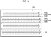
- FIG. 2 and FIG. 3 are a schematic plan view and a cross-sectional view of a secondary battery, respectively, according to embodiments of the present disclosure.
- FIG. 3 is a cross-sectional view taken along a line I-I' shown in FIG. 2 in a thickness direction of the secondary battery.
- illustrations of a cathode, an anode, and a separator are omitted in FIG. 2 .
- the secondary battery may include a cathode 100, an anode 130, and a separator 140.
- the secondary battery may be provided as a lithium secondary battery.
- the cathode 100 may include a cathode current collector 105 and a cathode active material layer 110 formed on or over at least one surface of the cathode current collector 105.
- the cathode active material layer 110 may be formed on or over both surfaces (e.g., an upper surface and a lower surface) of the cathode current collector 105.
- the cathode active material layer 110 may be formed on or over each of the upper surface and the lower surface of the cathode current collector 105.
- the cathode current collector 105 may include, e.g., stainless steel, nickel, aluminum, titanium, copper, or an alloy thereof. In an embodiment, the cathode current collector 105 may include aluminum or an aluminum alloy.
- the cathode active material layer 120 may include a cathode active material, a binder and/or a conductive material.
- a cathode slurry may be prepared by mixing and stirring the cathode active material with the binder and/or the conductive material in a solvent.
- the cathode slurry may be coated on the cathode current collector 105, and then dried and pressed to form the cathode active material layer 110.
- cathode active material may include a lithium iron phosphate-based compound, a lithium cobalt-based oxide, a lithium manganese-based oxide, a lithium nickel-based oxide, a lithium composite oxide.
- the cathode active material may include a layered compound such as lithium cobalt oxide (LiCoO 2 ) or lithium nickel oxide (LiNiO 2 ), a lithium manganese oxide such as LiMnO 3 , LiMn 2 O 3 and LiMnO 2 , lithium copper oxide (Li 2 CuO 2 ), a vanadium oxide such as LiV 3 O 8 , LiFe 3 O 4 , V 2 O 5 and Cu 2 VO 7 , a lithium iron phosphate oxide such as LiFePO 4 , etc.
- a layered compound such as lithium cobalt oxide (LiCoO 2 ) or lithium nickel oxide (LiNiO 2 ), a lithium manganese oxide such as LiMnO 3 , LiMn 2 O 3 and LiMnO 2 , lithium copper oxide (Li 2 CuO 2 ), a vanadium oxide such as LiV 3 O 8 , LiFe 3 O 4 , V 2 O 5 and Cu 2 VO 7 , a lithium iron
- the cathode active material may contain a compound represented by Chemical Formula 1.
- Chemical Formula 1 Li a Ni b M 1-b O 2
- M may include at least one element of Na, Mg, Ca, Y, Ti, Zr, Hf, V, Nb, Ta, Cr, Mo, W, Mn, Co, Fe, Cu, Ag, Zn, B, Al, Ga, C, Si, Sn, Ba, and Sr.
- the cathode active material above may further include at least one of cobalt (Co) and manganese (Mn).
- Co cobalt
- Mn manganese
- a nickel-cobalt-manganese (NCM)-based lithium oxide may be used as the cathode active material.
- Nickel (Ni) may be provided as a metal related to the capacity of the lithium secondary battery. As a content of nickel increases, capacity and power of the lithium secondary battery may be increased. However, an excessively high content of Ni may be disadvantageous from aspects of mechanical and electrical stability.
- Conductivity or resistance of the lithium secondary battery may be improved by cobalt (Co), and mechanical and electrical stability of the lithium secondary battery may be improved by manganese (Mn).
- Co cobalt
- Mn manganese
- the chemical structure represented by Chemical Formula 1 represents a lattice structure of the cathode active material or a bonding relationship included in the crystal structure, and does not exclude introduction of an additional element.
- M may serve as a main active element of the cathode active material.
- Chemical Formula 1 is provided to express the bonding relationship of the main active element and is to be interpreted as encompassing the introduction and substitution of the additional element.
- an auxiliary element may be further included in addition to the main active element to improve the chemical stability of the cathode active material or the crystal structure.
- the auxiliary element may be mixed together in the crystal structure to form a bond, and this case should be understood to be included within a range of the chemical structure represented by Chemical Formula 1.
- the binder may include a vinylidene fluoride-hexafluoropropylene copolymer (PVDF-co-HFP), polyvinylidene fluoride (PVDF), polyacrylonitrile, polymethylmethacrylate, polyvinyl alcohol, polyvinylpyrrolidone, polyethylene, polypropylene, polyacrylic acid, styrene-butadiene rubber (SBR), etc., and may be used together with a thickener such as carboxymethyl cellulose (CMC).
- PVDF-co-HFP vinylidene fluoride-hexafluoropropylene copolymer
- PVDF polyvinylidene fluoride
- polyacrylonitrile polymethylmethacrylate
- polyvinyl alcohol polyvinylpyrrolidone
- polyethylene polyethylene
- polypropylene polyacrylic acid
- SBR styrene-butadiene rubber
- CMC carboxymethyl cellulose
- a PVDF-based binder may be used as a binder for forming the cathode. Accordingly, a content of the binder for forming the cathode active material layer 110 may be reduced, and the content of the cathode active material may be relatively increased, thereby improving the power and capacity of the secondary battery.
- the conductive material may include a carbon-based conductive material such as graphite, carbon black, a carbon nanofiber and carbon nanotube and/or a metal-based conductive material such as tin, tin oxide, zinc oxide, titanium oxide and a metal fiber.
- a carbon-based conductive material such as graphite, carbon black, a carbon nanofiber and carbon nanotube
- a metal-based conductive material such as tin, tin oxide, zinc oxide, titanium oxide and a metal fiber.
- an electrode density of the cathode 100 may be in a range from 3.0 g/cc to 3.9 g/cc, and may be in a range from 3.2 g/cc to 3.8 g/cc.
- the anode 130 may include an anode current collector 125 and an anode active material layer 120 formed on or over at least one surface of the anode current collector 125.
- the anode active material layer 120 may be formed on or over both surfaces (e.g., upper surface and lower surface) of the anode current collector 125.
- the anode active material layer 120 may be coated on both the upper and lower surfaces of the anode current collector 125.
- the anode active material layer 120 may directly contact the surface of the anode current collector 125.
- the anode current collector 125 may include gold, stainless steel, nickel, aluminum, titanium, copper, or an alloy thereof. In an embodiment, the anode current collector 125 may include copper or a copper alloy.
- the anode active material layer 120 may include the cathode active material according to the above-described embodiments.
- the anode active material may be mixed and stirred with a binder, a conductive material, and/or a dispersive agent in a solvent to prepare an anode slurry.
- the anode slurry may be coated on the anode current collector 125, and then dried and pressed (rolled) to form the anode active material layer 120.
- the binder and the conductive material may be used as the binder and the conductive material.
- the binder for forming the anode may include, e.g., styrene-butadiene rubber (SBR) or an acrylic binder for compatibility with a graphite-based active material and may be used together with a thickener such as carboxymethyl cellulose (CMC).
- SBR styrene-butadiene rubber
- CMC carboxymethyl cellulose
- an electrode density of the anode 130 may be in a range from 1.0 g/cc to 1.9 g/cc.
- an area e.g., a contact area with the separator 140
- a volume of the anode 130 may be greater than an area and/or a volume of the cathode 100. Accordingly, lithium ions generated from the cathode 100 may be easily transferred to the anode 130 without, e.g., being precipitated, thereby further improving output power and capacity properties.
- the separator 140 may be interposed between the cathode 100 and the anode 130.
- the separator 140 may include a porous polymer film formed of a polyolefin-based polymer such as an ethylene homopolymer, a propylene homopolymer, an ethylene/butene copolymer, an ethylene/hexene copolymer, an ethylene/methacrylate copolymer, etc.
- the separator 140 may include a non-woven fabric formed of a glass fiber having a high melting point, a polyethylene terephthalate fiber, etc.
- the separator 140 may extend in a length direction between the cathode 100 and the anode 130. A plurality of the cathodes 100 and the anodes 130 may be stacked using the separator 140 in the thickness direction.
- an electrode cell may be defined by the cathode 100, the anode 130 and the separator 140, and a plurality of electrode cells may be stacked to form an electrode assembly 150.
- the electrode assembly 150 may be formed by winding, stacking, folding, etc. of the separator 140.
- the electrode assembly 150 may be accommodated in the case 160, and an electrolyte solution may also be injected into the case 160.
- the case 160 may include, e.g., a pouch, a can, etc.
- a non-aqueous electrolyte solution may be used as the electrolyte solution.
- the non-aqueous electrolyte solution may include a lithium salt as an electrolyte and an organic solvent.
- the lithium salt may be represented by Li + X - , and examples of an anion (X - ) of the lithium salt may include F - , Cl - , Br - , I - , NO 3 - , N(CN) 2 - , BF 4 - , ClO 4 - , PF 6 -, (CF 3 ) 2 PF 4 - , (CF 3 ) 3 PF 3 - , (CF 3 ) 4 PF 2 - , (CF 3 ) 5 PF - , (CF 3 ) 6 P - , CF 3 SO 3 - , CF 3 CF 2 SO 3 - , (CF 3 SO 2 ) 2 N - , (FSO 2 ) 2 N - ; CF 3 CF 2 (CF 3 ) 2 CO - , (CF 3 SO 2 ) 2 CH -
- the organic solvent may include, e.g., propylene carbonate (PC), ethylene carbonate (EC), diethyl carbonate (DEC), dimethyl carbonate (DMC), ethylmethyl carbonate (EMC), methylpropyl carbonate, dipropyl carbonate, dimethyl sulfoxide, acetonitrile, dimethoxyethane, diethoxyethane, vinylene carbonate, gamma-butyrolactone, propylene sulfite, tetrahydrofuran, etc. These may be used alone or in a combination of two or more therefrom.
- PC propylene carbonate
- EC ethylene carbonate
- DEC diethyl carbonate
- DMC dimethyl carbonate
- EMC ethylmethyl carbonate
- methylpropyl carbonate dipropyl carbonate
- dimethyl sulfoxide acetonitrile, dimethoxyethane, diethoxyethane, vinylene carbonate,
- electrode tabs may protrude from the cathode current collector 105 and the anode current collector 125 included in each electrode cell, respectively, to one side of the case 160.
- the electrode tabs may be fused together with the one side of the case 160, and may be connected to electrode leads (a cathode lead 107 and an anode lead 127) being exposed or extending to an outside of the case 160.
- FIG. 2 illustrates that the cathode lead 107 and the anode lead 127 are formed at the same side of the lithium secondary battery or the case 160, but the cathode lead 107 and the anode lead 127 may be formed at opposite sides.
- the cathode lead 107 may be formed at one end of the case 160
- the anode lead 127 may be formed at the other end of the case 160.
- the lithium secondary battery may be manufactured in, for example, a cylindrical type using a can, a prismatic type, a pouch type, a coin type, etc.
- the lithium secondary battery includes the anode active material as described above to have improved cycle properties, long-term storage stability, and charge/discharge capacity. Additionally, e.g., crystallinity of the silicon-based active material or a content of fine particles may be controlled to improve conductivity of ions or electrons. Therefore, lithium ions may be easily intercalated and de-intercalated, side reactions between the anode active material and the electrolyte solution may be suppressed, and degradation of the capacity and power of the battery may be prevented.
- crystallinity of the silicon-based active material or a content of fine particles may be controlled to improve conductivity of ions or electrons. Therefore, lithium ions may be easily intercalated and de-intercalated, side reactions between the anode active material and the electrolyte solution may be suppressed, and degradation of the capacity and power of the battery may be prevented.
- SiOx (0 ⁇ x ⁇ 2) was introduced into a ball mill container and pulverized so that D 50 became 7 ⁇ m or less.
- the pulverized particles (core particles) were subjected to a chemical vapor deposition (CVD) treatment at a temperature from 550°C to 1150°C in a hydrocarbon gas atmosphere such as acetylene, ethylene, propylene, methane, etc., to form a carbon coating on the core particles.
- CVD chemical vapor deposition
- Silicon-based active materials A-1 to A-6 were prepared under different pulverizing process conditions and CVD process conditions.
- the conditions of the pulverizing process for SiOx were adjusted such that a particle size distribution of the silicon-based active material satisfied Table 1 below, and the CVD process conditions were adjusted such that I C /I A satisfied Table 1 below.
- the silicon-based active material and a carbon-based active material were mixed in a weight ratio of 5:95 to prepare an anode active material.
- the silicon-based active material and the carbon-based active material were mixed in a weight ratio of 7:93 to prepare an anode active material.
- Each of the silicon-based active materials A-1 to A-6 was added to ethanol. After the ethanol was ultrasonically dispersed, a volume-weighted particle size distribution curve was obtained by measuring a diffraction pattern difference according to a particle size using a laser diffraction particle size analyzer (Microtrac MT 3000) in a refractive index range from 5% to 10%.
- a laser diffraction particle size analyzer Mocrotrac MT 3000
- D min was measured as the smallest particle diameter in the volume-weighted particle size distribution curve, and particle diameters at 10%, 50%, 90% and 99.9% of the volume fractions were measured to obtain D 10 , D 50 , D 90 and D max .
- a volume fraction of fine particles having a diameter of 2 ⁇ m or less was measured, and a content of the fine particles was calculated from the measured volume fraction and a true density of the silicon-based active material.
- a specific surface area of each of the silicon-based active materials A-1 to A-6 was measured by a BET method using an amount of nitrogen gas adsorption with a specific surface area measuring apparatus (MOUNTECH Macsorb HM Model-1208).
- the silicon-based active material was put in a test tube, heated to a temperature of 300°C, and a nitrogen gas was supplied for 1 hour. Thereafter, a weight of the sample was calculated, and a specific surface area of the sample was measured using the specific surface area measuring apparatus.
- Table 1 shows physical properties of the silicon-based active material contained in the anode active material in each of Examples and Comparative Examples.
- the anode active material according to Example 1 is a mixture in which the silicon-based active material A-1 and the carbon-based active material were mixed in a weight ratio of 5: 95.
- the anode active material, carbon nanotubes (CNT) and Super-P as a conductive material, carboxymethyl cellulose (CMC) as a thickener, and SBR as a binder were mixed in a weight ratio of 97.2:0.1:1.2:1.5 (anode active material : conductive material : thickener : binder) to prepare an anode slurry. Thereafter, the anode slurry was coated on a copper substrate (Cu foil), dried and pressed to prepare an anode having a mixture density of 5 mg/cm 2 to 12 mg/cm 2 (based on a cross-section) and 1.7 g/cc.
- a cathode slurry was prepared by mixing LiNi 0.8 Co 0.1 Mn 0.1 O 2 as a cathode active material, carbon black as a conductive material, and polyvinylidene fluoride (PVDF) as a binder in a weight ratio of 92:5:3.
- the cathode slurry was coated on an aluminum substrate, dried and pressed to prepare a cathode.
- Li foil was used as a cathode, and the anode and the cathode were disposed with a polyethylene separator (13 ⁇ m) interposed therebetween.
- a coin cell-type secondary battery was manufactured by using 1M LiPF 6 solution including 1 wt% of FEC (in a mixed solvent of ethylene carbonate (EC) and ethylmethyl carbonate (EMC); 30vol%:70 vol%) as an electrolyte solution. The secondary battery was left at room temperature (25°C) for 12 hours for impregnation of the electrolyte solution.
- the secondary batteries (coin cells) according to Examples and Comparative Examples were stabilized by performing charge (CC/CV, rate 0.1C, lower limit voltage 0.005V, cut-off current 0.01C) and discharge (CC, 0.1C, upper limit voltage 1.5V cut-off) for an initial five cycles at 25°C.
- the cathode and the anode were disposed with a polyethylene (PE) separator (13 ⁇ m) interposed therebetween to form an electrode cell, and the electrode cells were stacked to form an electrode assembly.
- PE polyethylene
- the electrode assembly was accommodated in a pouch and electrode tab portions were fused.
- Charging/discharging of 600 cycles were repeatedly performed using charging (CC/CV, 0.5C, upper limit voltage 4.2V, cut-off current 0.05C) and discharging (CC, 0.5C, lower limit voltage 2.5V cut-off) at 45°C as one cycle for the secondary batteries (full cells) according to Examples and Comparative Examples.
- a life-span property was evaluated as a percentage of a discharge capacity at 600th cycle relative to a discharge capacity at the 1st cycle.
- Charging (CC/CV, 0.5C, upper limit voltage 4.2V, cut-off current 0.05C) and discharging (CC, 0.5C, lower limit voltage 2.5V cut-off) were performed once for the secondary batteries (full cells) according to Examples and Comparative Examples at 25°C, and then charged at 100% SOC and stored at 60°C for 12 weeks.
- a high-temperature storage property was evaluated as a percentage of a discharge capacity after 12 weeks relative to an initial discharge capacity.
Landscapes
- Chemical & Material Sciences (AREA)
- Chemical Kinetics & Catalysis (AREA)
- Electrochemistry (AREA)
- General Chemical & Material Sciences (AREA)
- Composite Materials (AREA)
- Engineering & Computer Science (AREA)
- Inorganic Chemistry (AREA)
- Manufacturing & Machinery (AREA)
- Materials Engineering (AREA)
- Battery Electrode And Active Subsutance (AREA)
Abstract
An anode active material for a lithium secondary battery includes a silicon-based active material that includes a core particle and a carbon coating formed on or over the core particle. The anode active material satisfies a specific relation within a specific range. A lithium secondary battery includes an anode including the anode active material, and a cathode facing the anode.
Description
- Embodiments of the present disclosure relate to an anode active material for a lithium secondary battery and a lithium secondary battery including the same.
- Secondary batteries can be charged and discharged repeatedly and are widely employed as power source of mobile electronic devices such as camcorders, mobile phones, laptop computers, and the like. Some examples of secondary batteries include, lithium secondary batteries, nickel-cadmium batteries, and nickel-hydrogen batteries. The lithium secondary batteries are more widely developed and applied than the other secondary batteries mainly because of their higher operational voltage, energy density per unit weight, charging rate, and their very compact dimensions.
- For example, the lithium secondary battery may include an electrode assembly including a cathode, an anode and a separation layer (separator), and an electrolyte immersing the electrode assembly. The lithium secondary battery may further include an outer case, for example a pouch type enclosing the electrode assembly and the electrolyte.
- The anode may contain a material such as a carbon-based (e.g., graphite), or a silicon-based material that can intercalate or store lithium ions during the battery operation as an anode active material. Repeat charging and discharging of the lithium secondary battery may cause mechanical and chemical damage or deterioration such as cracks of the active material particles due to expansion and contraction, degraded or less contact between the anode active material particles, and short-circuits.
- Efforts to improve the stability of the anode active material are complex because changing the structure, or shape, of the particles may also change their conductivity and the power of the secondary battery. Hence, novel solutions are needed that improve the stability of the anode active material particle, prevent a decrease in the conductivity and power/capacity properties of the secondary battery.
- Embodiments of the present disclosure solve the aforementioned problems of the prior art. According to an embodiment of the present disclosure, there is provided an anode active material for a lithium secondary battery having improved stability, electrical property and activity.
- According to another embodiment of the present disclosure, there is provided a lithium secondary battery employing the inventive anode active material and exhibiting significantly improved electrical properties and activity. The term activity as used here refers to the ability of the battery to perform its intended functions effectively, and encompasses various aspects of the battery performance, such as capacity, charging and discharging rates, cycle life, and overall efficiency.
- According to an embodiment of the present disclosure, an anode active material for a lithium secondary battery is provided which includes a silicon-based active material that includes a core particle and a carbon coating formed on or over the core particle. The carbon coating may be formed on or over the core particle and be in direct contact with the core particle. The anode active material has an SA defined by the following Equation 1 in a range from 0.5 to 2.0.

- In Equation 1, SPAN represents (D90-D10)/D50, and D10, D50 and D90 are particle diameters at volume fractions of 10%, 50% and 90%, respectively, in a volume-weighted particle size distribution of the silicon-based active material. SSA is a specific surface area in a unit of m2/g of the silicon-based active material. IC is a peak intensity corresponding to a crystalline region of the silicon-based active material obtained through a Raman spectroscopy, and IA is a peak intensity corresponding to an amorphous region of the silicon-based active material obtained through the Raman spectroscopy.
- In some embodiments, Ic is a maximum value of peak intensities measured at a Raman shift of 500 cm-1 to 530 cm-1, and IA is a maximum value of peak intensities measured at a Raman shift of 450 cm-1 to 490 cm-1.
- In some embodiments, the core particle may include a silicon oxide of the formula SiOx (0<x<2).
- In some embodiments, the carbon coating may include a crystalline carbon or an amorphous carbon.
- In some embodiments, the carbon coating may cover 50% or more of an outer surface of the core particle.
- In some embodiments, the SPAN in Equation 1 may be in a range from 0.7 to 1.2.
- In some embodiments, the specific surface area of the silicon-based active material may be in a range from 1 m2/g to 2 m2/g.
- In some embodiments, SB defined by Equation 2 may be in a range from 1.5 to 3.0.

- In Equation 2, D50 is a particle diameter at volume fractions of 50% in the volume-weighted particle size distribution of the silicon-based active material. SSA is a specific surface area in a unit of m2/g of the silicon-based active material.
- In some embodiments, a content of particles having a diameter of 2 µm or less in the silicon-based active material may be in a range from 0.2 wt% to 1.0 wt% based on a total weight of the silicon-based active material.
- In some embodiments, a minimum particle diameter (Dmin) of the silicon-based active material may be 1.1 µm or more.
- In some embodiments, the minimum particle diameter (Dmin) of the silicon-based active material may be in a range from 1.5 µm to 7 µm.
- In some embodiments, a maximum particle diameter (Dmax) of the silicon-based active material may be 25 µm or less.
- In some embodiments, the maximum particle diameter (Dmax) of the silicon-based active material may be in a range from 10 µm to 20 µm.
- In some embodiments, the anode active material may further include a carbon-based active material.
- In some embodiments, the carbon-based active material may include artificial graphite, natural graphite or a mixture thereof.
- In some embodiments, a content of the silicon-based active material may be greater than 0 wt% and less than or equal to 15 wt% based on a total weight of the anode active material.
- A lithium secondary battery includes an anode including the anode active material for a lithium secondary battery according to the above-described embodiments, and a cathode facing the anode.
- The anode active material according to embodiments of the present disclosure may include a silicon-based active material including a core particle and a carbon coating formed on or over the core particle. An energy density and charge/discharge capacity of the anode active material may be enhanced by the core particle.
- Damage such as cracks, fractures and side reactions of the core particle may be prevented by the carbon coating. Additionally, the carbon coating may additionally provide a moving path of ions (e.g., lithium ions) or electrons, thereby improving power properties of the secondary battery.
- The silicon-based active material may have a specific surface area within a desirable range. Accordingly, ion conductivity and chemical stability may be improved, and life-span properties may be improved. The silicon-based active material may have a desirable particle size distribution. Therefore, side reactions with the electrolyte and the resulting electrolyte consumption may be reduced, and long-term life-span and high-temperature storage properties may be improved while enhancing power and life-span.
- The lithium secondary battery of the present disclosure may be widely applied in green technology fields such as an electric vehicle, a battery charging station, a solar power generation, a wind power generation, etc., using a battery. The lithium secondary battery according to the present disclosure may be used for eco-friendly electric vehicles and hybrid vehicles to prevent a climate change by suppressing air pollution and greenhouse gas emission.
- These and other features and advantages of the present invention will become better understood from the following drawings and detailed description of specific example embodiments of the present disclosure.
-
-
FIG. 1 is a schematic cross-sectional view illustrating an anode with an anode active material on the anode for a lithium secondary battery in accordance with embodiments of the present disclosure. -
FIG. 2 is a schematic plan view illustrating a lithium secondary battery in accordance with embodiments of the present disclosure. -
FIG. 3 is a schematic cross-sectional view illustrating a lithium secondary battery in accordance with embodiments of the present disclosure. - According to embodiments of the present disclosure, an anode active material for a lithium secondary battery (hereinafter, that may be abbreviated as an anode active material) including a silicon-containing active material that includes a carbon-coating is provided.
- According to embodiments of the present disclosure, a lithium secondary battery including the anode active material is provided.
- Hereinafter, the anode active material and the lithium secondary battery according to embodiments of the present disclosure will be described in more detail with reference to specific embodiments and the accompanying drawings.
-
FIG. 1 is a schematic cross-sectional view illustrating an anode for a lithium secondary battery in accordance with embodiments of the present disclosure. - Referring to
FIG. 1 , an anode for a lithium secondary battery includes an anodecurrent collector 125 and an anodeactive material layer 50 formed on or over the anodecurrent collector 125. The anode active material layer contains an anode active material comprising a plurality of particles. The anodeactive material layer 50 may be formed directly on a top surface of thecurrent collector 125 as shown in the illustrated embodiment ofFIG. 1 . - The anode active material includes a silicon-based active material (e.g., a silicon-containing active material). The silicon-based
active material particle 50 includes acore particle 70 and acarbon coating 90 formed on or over thecore particle 70. - The
core particle 70 may include silicon (Si), a silicon oxide (SiOx) (0<x<2), or a silicon-metal alloy. These may be used alone or in a combination of two or more therefrom. An anode activity may be provided by thecore particles 70. - In an embodiment, the silicon oxide (SiOx, 0<x<2) may include a lithium compound or a magnesium compound. For example, the SiOx may be pretreated with lithium or magnesium. For example, the SiOx may include lithium silicate or magnesium silicate (e.g., MgO:XSiO2, where X denotes the average mole ratio of SiO2 to MgO).
- The
core particles 70 may include a silicon-based material to have high energy density, and initial efficiency and charge/discharge capacity of the anode active material may be improved. However, a silicon-based material may react with an electrolyte solution to form a solid electrolyte interphase (SEI), and the electrolyte solution may be depleted by irreversible decomposition of the electrolyte solution, thereby increasing as resistance. - The
carbon coating 90 may at least partially surround thecore particle 70 so that it may block the exposure of thecore particle 70 to the electrolyte solution to maintain the activity of the anode. Stated differently, thecarbon coating 90 may at least partially cover thecore particle 70 to prevent the electrolyte from contacting thecore particle 70. - For example, for existing anode active materials, when charging/discharging of the secondary battery is repeated, because of the contact with the electrolyte and swelling of the anode active material, the surface of the
core particle 70 may be mechanically damaged. Contact of the electrolyte with thecore particle 70 may also cause chemical damage to the surface of thecore particle 70. Furthermore, gas generation has been observed caused by side reactions as the surface of thecore particle 70 comes into contact with the electrolyte solution. - The present invention overcomes these problems by employing the
carbon coating 90 which suppresses swelling and expansion of thecore particle 70 due to repeated charging and discharging, and also prevents side reactions of thecore particle 70 with the electrolyte solution, thereby improving life-span and capacity retention. - In an embodiment, the
carbon coating 90 may be formed by a chemical vapor deposition (CVD), a physical vapor deposition (PVD), or thermal deposition of a hydrocarbon gas on thecore particle 70. For example, thecarbon coating 90 may be formed using a hydrocarbon gas, a coal-based material or a petroleum-based material. - In some embodiments, the
carbon coating 90 may include an amorphous carbon such as hard carbon, soft carbon, fired coke, a mesophase pitch carbon and/or a crystalline carbon such as natural graphite and artificial graphite. These may be used alone or in any combination of two or more thereof. - In one embodiment, the
carbon coating 90 may include the amorphous carbon, e.g., hard carbon and/or soft carbon. The amorphous carbon may have a structure where lithium ions may be easily intercalated, and thus may participate in a reaction even in a low state of charge (SOC) part where the silicon-based active material mainly reacts. Thus, deterioration of thecore particles 70 due to repeated charging and discharging may be suppressed. - As illustrated in the embodiment of
FIG. 1 , at least a portion of an outer surface of thecore particle 70 may be surrounded by thecarbon coating 90. In an embodiment, thecarbon coating 90 may be partially formed on the outer surface of thecore particle 70. For example, thecarbon coating 90 may cover 30% or more, or 50% or more of an area of the outer surface of thecore particle 70. - Within the above range, the contact between the
core particle 70 and the electrolyte solution may be efficiently blocked. Accordingly, the side reaction with the electrolyte solution and the gas generation may be reduced, thereby improving the life-span properties and high temperature properties of the secondary battery. - The
carbon coating 90 may be discontinuously distributed on thecore particle 70. For example, thecarbon coating 90 may exist in the form of a plurality of islands in local areas of the outer surface of thecore particle 70. - In an embodiment, the
carbon coating 90 may be continuously and uniformly distributed on the outer surface of thecore particle 70. For example, thecarbon coating 90 may exist in the form of a film (e.g., a thin film form) covering at least a portion of the outer surface of thecore particle 70. - If the
carbon coating 90 is uniformly distributed on the surface of thecore particle 70, lithium ions may be intercalated and deintercalated from all surfaces of the anode active material. Accordingly, power properties and rapid charging properties may be improved. - In some embodiments, a thickness of the
carbon coating 90 may be in a range from about 0.001 µm to about 0.5 µm. In an embodiment, the thickness of thecarbon coating 90 may be in a range from about 0.001 µm to about 0.3 µm, or from about 0.001 µm to about 0.1 µm. Within the above range, physical damages and structural collapse of thecore particle 70 due to repeated charging and discharging may be prevented while maintaining high capacity and high rate properties of the secondary battery. - In some embodiments, a density of the
carbon coating 90 may be in a range from about 0.5 g/cm3 to about 1.9 g/cm3. Within this range, the silicon-basedactive material particle 50 may be structurally stabilized by preventing physical damages to thecore particle 70 due to the volume expansion. - In some embodiments, a content of the
carbon coating 90 may be in a range from 0.01 weight percent (wt%) to 10 wt%, or 1 wt% to 5 wt% based on a total weight of the silicon-based active material. Within this range, thecore particle 70 may be entirely covered with an appropriate thickness by thecarbon coating 90, thereby suppressing damages caused by volume change of thecore particles 70. Additionally, resistance and electrochemical properties of an electrode may be improved by preventing a disconnection of a contact due to charging/discharging of the secondary battery. - The content of the
carbon coating 90 may be measured using a thermogravimetric analysis (TGA). For example, the content of thecarbon coating 90 may be calculated by measuring a weight change by a heat treatment and an injection of nitrogen (N2) gas. For example, a mass loss amount of the silicon-based active material may be measured from a graph for change in weigh against temperature by TGA, and the content of thecarbon coating 90 may be calculated through the mass loss amount. - The silicon-based active material may include silicon (Si) having a crystalline structure. The crystalline structure may refer to a structure where a shape of a single silicon positioned within an inside of a particle has crystallinity.
- In some embodiments, the silicon-based active material may include silicon having an amorphous structure. The amorphous structure may refer to a structure where the shape of the single silicon positioned within the inside of the particles is amorphous or where a crystallite size is excessively small and substantially non-measurable by a Scherrer equation.
- In the anode active material according to embodiments of the present disclosure, SA defined by the following Equation 1 is in a range from 0.5 to 2.0.

- SPAN represents (D90-D10>)/D50
- D50 is a volume average particle diameter of the silicon-based active material. For example, D50 may refer to a particle diameter at a volume fraction of 50% when a volume-weighted particle distribution of the silicon-based active material is measured using a laser diffraction particle size analyzer and accumulated from the smallest particle in the measured volume-weighted particle size distribution.
- D10 refers to a particle diameter at a volume fraction of 10% in the volume-weighted particle size distribution of the silicon-based active material.
- D90 refers to a particle diameter at a volume fraction of 90% in a volume-weighted particle size distribution of the silicon-based active material.
- The term "particle size" or "particle diameter" used herein may refer to the longest diameter of any particle. The particle diameter may be measured using a scanning electron microscope (SEM), a transmission electron microscope (TEM), a light scattering method, or a laser diffraction method.
- A specific surface area (SSA) may be a numerical value of a specific surface area of the silicon-based active material. For example, SSA may refer to a dimensionless value obtained by removing a unit from a specific surface area of the silicon-based
active material 50 measured in a unit of m2/g. - In a Raman spectrum obtained by Raman spectroscopy, IC is a peak intensity corresponding to a crystalline region (e.g., a region having a crystalline Si structure) of the silicon-based active material, and IA is a peak intensity corresponding to an amorphous region (e.g., a region having an amorphous Si structure).
- For example, a ratio of the crystalline region in the silicon-based active material may be calculated from IC, and a ratio of the amorphous region in the silicon-based active material may be calculated from IA.
- For example, IC may be a maximum value of a peak intensity measured at a Raman shift from 500 cm-1 to 530 cm-1, from 505 cm-1 to 530 cm-1, or from 510 cm-1 to 530 cm-1 in the Raman spectrum.
- For example, IA may be a maximum value of a peak intensity measured in a Raman shift from 450 cm-1 to 495 cm-1, 460 cm-1 or more and less than 490 cm-1, or from 465 cm-1 to 485 cm-1 in the Raman spectrum.
- If SA is less than 0.5, the side reaction between the electrolyte solution and the anode active material may be increased to cause fractures and cracks on a surface of the anode active material, and a reversible capacity of the anode active material may be decreased to degrade initial efficiency and capacity properties.
- For example, an area where the anode active material contacts the electrolyte solution may increase, and the side reaction may be accelerated, and mechanical and structural stability of the active material may be degraded due to the gas generation. Accordingly, a thickness of the battery may increase during charging/discharging in the anode including the silicon-based active material.
- If SA exceeds 2.0, swelling of a battery may increase during charging/discharging, and the anode active material may be deteriorated. A movement path of ions may be reduced, intercalation/de-intercalation process of ions may be hindered, and charging/discharging capacities may be degraded.
- In an embodiment, SA may be in a range from 0.6 to 1.8, or from 0.7 to 1.7.
- As IC/IA of the silicon-based active material increases, growth of the crystalline region (c-Si) compared to the amorphous region (a-Si) in the silicon-based active material may be promoted. As IC/IA decreases, growth of c-Si compared to a-Si may be suppressed. A content of c-Si may be increased or decreased by adjusting the value of IC/IA. For example, as the ratio increases and the content of c-Si in the silicon-based
active material 50 increases, a volume change in the charging/discharging process may be increased, and the life-span properties of a secondary battery may be deteriorated. - In some embodiments, IC/IA may be greater than 0, and less than or equal to 3.0. Within the above range, the volume expansion during charging/discharging and degradation of the anode active material may be suppressed, thereby improving battery properties. For example, IC/IA may have a value in a range from 1.0 to 3.0, or from 1.5 to 3.0.
- In some embodiments, D50 may be 7 µm or less, or 6 µm or less.
- In some embodiments, D10 may be 5 µm or less, or 4 µm or less.
- In some embodiments, D90 may be 10 µm or less, or 9.5 µm or less.
- SPAN of the silicon-based active material may be in a range from 0.7 to 1.2. If the SPAN value exceeds 1.2, the range of the particle size distribution may increase, and the volume change and thickness increase of the anode due to charging and discharging may be increased.
- When the SPAN value is less than 0.7, a width of the particle size distribution may become narrow and the diameter of the particles may become uniform. Accordingly, a packing density of the anode active material particles may be lowered, and the contact between the anode active material particles may be degraded, and the life-span properties may be lowered.
- In some embodiments, SPAN may be in a range from 0.8 to 1.1, e.g., from 0.85 to 1.0, or from 0.8 to 0.9.
- In some embodiments, the silicon-based active material may have the specific surface area from 1 m2/g to 2 m2/g. For example, the specific surface area may be measured using a Brunauer-Emmett-Teller (BET) measurement method by a nitrogen gas adsorption amount using a specific surface area measuring apparatus.
- If the specific surface part of the silicon-based active material is 2 m2/g or less, the contact between the electrolyte solution and the active material may become lowered, and mechanical and structural stability of the silicon-based active material may be improved.
- In some embodiments, the silicon-based active material may have a specific surface area from about 1.3 m2/g to about 1.9 m2/g, from about 1.4 m2/g to about 1.8 m2/g, or from about 1.5 m2/g to about 1.8 m2/g. Within the above range, cycle properties may be improved and intercalation and de-intercalation of the lithium ions may be promoted thereby improving charging/discharging capacity and rapid charging performance.
- For example, damages and degradation of the active material particles may occur due to the volume change during charging/discharging of the secondary battery. In this case, loss of a contact point between the active material particles may occur, and the life-span properties of the secondary battery may be degraded. In example embodiments, the specific surface area of the silicon-based active material may be controlled, and thus the damages and degradation of the active material particles caused by the volume change may be avoided or reduced. Thus, the life-span properties of the secondary battery may be improved.
- According to embodiments, the silicon-based active material may have a minimum particle diameter (Dmin) of 1.1 µm or more. Dmin may be a smallest particle diameter measured from the volume-weighted particle size distribution of the silicon-based active material. If Dmin of the silicon-based active material is 1.1 µm or more, the contact area between the silicon-based
active material 50 and the electrolyte solution may be controlled, thereby preventing collapse/regeneration of the solid electrolyte interface layer. Therefore, consumption of the electrolyte solution may be prevented, and the capacity and life-span properties of the secondary battery may be enhanced. - In some embodiments, the minimum particle diameter (Dmin) of the silicon-based
active material 50 may be in a range from about 1.5 µm to about 7 µm, or from about 2 µm to about 6 µm. Within this range, a diffusion distance of the lithium ions may be reduced to improve power properties and a charging rate, and initial charging/discharging capacity may be enhanced. Additionally, a conductivity of the lithium ions may be enhanced while suppressing the side reactions by controlling the contact area of the silicon-based active material. Thus, the power and life-span properties of the lithium secondary battery may be improved. - In some embodiments, a maximum particle diameter (Dmax) of the silicon-based active material may be 25 µm or less, e.g., in a range from about 10 µm to about 20 µm. Dmax may refer to a particle diameter at a volume fraction of 99.9% when the particles are accumulated from the smallest particle in the volume-weighted particle size distribution of the silicon-based active material. Within this range, a particle diameter difference between the particles in the silicon-based active material may be reduced. Accordingly, a particle diameter deviation may be reduced, thereby improving the cycle properties and energy density.
- In some embodiments, the silicon-based active material may include particles having a diameter of 2 µm or less (hereinafter, referred to as fine particles).
- In some embodiments, a content of the fine particles may be in a range from 0.2 wt% to 1.0 wt% based on the total weight of the silicon-based active material. Within the above range, dispersion of the silicon-based active material may be improved and the contact area between the silicon-based active material and the electrolyte solution may be reduced. Thus, the side reaction may be suppressed, and the life-span and capacity retention of the secondary battery may be enhanced by a reversible charging and discharging behavior.
- The content of the fine particles may be calculated from a volume fraction of the particles having a diameter of 2 µm or less in the volume-weighted particle size distribution of the silicon-based active material.
- In the anode active material according to some embodiments, SB defined by Equation 2 below may be in a range from 1.5 to 3.0.

- If SB exceeds 3.0, a filling density of the anode active material may be decreased, and the thickness change of the anode may be increased and the contact between the active material particles may be degraded. Accordingly, the life-span and capacity properties of the secondary battery may be degraded.
- If SB is less than 1.5, uniformity of the anode active material layer may be degraded and chemical stability may also be degraded. Further, the side reactions between the electrolyte solution and the anode active material may increase, thereby increasing the volume change of the secondary battery and degrading the life-span and capacity properties.
- In an embodiment, SB may be in a range from 1.5 to 2.7, or from 1.6 to 2.6. Within the above range, the capacity, power and life-span properties of the secondary battery may be further improved.
- In example embodiments, the anode active material may further include a carbon-based active material. For example, the anode active material may further include the carbon-based active material particles that are distinct from the silicon-based active material particles. For example, the anode active material may include a mixture of the silicon-based active material and the carbon-based active material.
- In some embodiments, the carbon-based active material may include an amorphous carbon such as fired coke, a mesophase pitch carbide, hard carbon and soft carbon and/or a crystalline carbon such as natural graphite and artificial graphite. These may be used alone or in a combination of two or more therefrom.
- In an embodiment, the carbon-based active material may include the crystalline carbon such as artificial graphite or natural graphite. For example, the crystalline carbon has a relatively high discharge capacity and life-span properties, thereby improving the energy density of the secondary battery. Additionally, high-temperature storage and high-temperature life-span properties of the battery may be improved by including thermally and chemically stable natural graphite and artificial graphite.
- In an embodiment, a crystallinity of the
carbon coating 90 may be less than that of the carbon-based active material. For example, the carbon-based active material may have a high crystallinity by firing a carbon precursor at a high temperature of 900°C or higher. - In some embodiments, a content of the
carbon coating 90 may be greater than 0 wt% and less than or equal to 10 wt%, or from 0.1 wt% to 8 wt% based a total weight of the anode active material. Within the above range, a coverage ratio of thecarbon coating 90 may become high, and the side reaction with the electrolyte solution may be prevented. Thus, the volume expansion of the silicon-based active material may be suppressed without reducing the energy density, and rate properties of the battery may be improved. - In some embodiments, the content of the silicon-based active material may be greater than 0 wt% and less than or equal to 15 wt% based on the total weight of the anode active material. Within the above range, the expansion of the anode active material and a short circuit in the electrode may be suppressed, and the life-span and capacity recovery properties may be improved.
-
FIG. 2 andFIG. 3 are a schematic plan view and a cross-sectional view of a secondary battery, respectively, according to embodiments of the present disclosure. For example,FIG. 3 is a cross-sectional view taken along a line I-I' shown inFIG. 2 in a thickness direction of the secondary battery. For convenience of descriptions, illustrations of a cathode, an anode, and a separator are omitted inFIG. 2 . - Referring to
FIGS. 2 and3 , the secondary battery may include acathode 100, ananode 130, and aseparator 140. - In some embodiments, the secondary battery may be provided as a lithium secondary battery.
- The
cathode 100 may include a cathodecurrent collector 105 and a cathodeactive material layer 110 formed on or over at least one surface of the cathodecurrent collector 105. In some embodiments, the cathodeactive material layer 110 may be formed on or over both surfaces (e.g., an upper surface and a lower surface) of the cathodecurrent collector 105. For example, the cathodeactive material layer 110 may be formed on or over each of the upper surface and the lower surface of the cathodecurrent collector 105. - The cathode
current collector 105 may include, e.g., stainless steel, nickel, aluminum, titanium, copper, or an alloy thereof. In an embodiment, the cathodecurrent collector 105 may include aluminum or an aluminum alloy. - The cathode
active material layer 120 may include a cathode active material, a binder and/or a conductive material. For example, a cathode slurry may be prepared by mixing and stirring the cathode active material with the binder and/or the conductive material in a solvent. The cathode slurry may be coated on the cathodecurrent collector 105, and then dried and pressed to form the cathodeactive material layer 110. - Examples of the cathode active material may include a lithium iron phosphate-based compound, a lithium cobalt-based oxide, a lithium manganese-based oxide, a lithium nickel-based oxide, a lithium composite oxide.
- For example, the cathode active material may include a layered compound such as lithium cobalt oxide (LiCoO2) or lithium nickel oxide (LiNiO2), a lithium manganese oxide such as LiMnO3, LiMn2O3 and LiMnO2, lithium copper oxide (Li2CuO2), a vanadium oxide such as LiV3O8, LiFe3O4, V2O5 and Cu2VO7, a lithium iron phosphate oxide such as LiFePO4, etc.
- In an embodiment, the cathode active material may contain a compound represented by Chemical Formula 1.
[Chemical Formula 1] LiaNibM1-bO2
- In Formula 1, 0.95≤a≤1.08, b ≥0.5, and M may include at least one element of Na, Mg, Ca, Y, Ti, Zr, Hf, V, Nb, Ta, Cr, Mo, W, Mn, Co, Fe, Cu, Ag, Zn, B, Al, Ga, C, Si, Sn, Ba, and Sr.
- In an embodiment, the cathode active material above may further include at least one of cobalt (Co) and manganese (Mn). For example, a nickel-cobalt-manganese (NCM)-based lithium oxide may be used as the cathode active material.
- Nickel (Ni) may be provided as a metal related to the capacity of the lithium secondary battery. As a content of nickel increases, capacity and power of the lithium secondary battery may be increased. However, an excessively high content of Ni may be disadvantageous from aspects of mechanical and electrical stability.
- Conductivity or resistance of the lithium secondary battery may be improved by cobalt (Co), and mechanical and electrical stability of the lithium secondary battery may be improved by manganese (Mn).
- The chemical structure represented by Chemical Formula 1 represents a lattice structure of the cathode active material or a bonding relationship included in the crystal structure, and does not exclude introduction of an additional element. For example, M may serve as a main active element of the cathode active material. Chemical Formula 1 is provided to express the bonding relationship of the main active element and is to be interpreted as encompassing the introduction and substitution of the additional element.
- In an embodiment, an auxiliary element may be further included in addition to the main active element to improve the chemical stability of the cathode active material or the crystal structure. The auxiliary element may be mixed together in the crystal structure to form a bond, and this case should be understood to be included within a range of the chemical structure represented by Chemical Formula 1.
- The binder may include a vinylidene fluoride-hexafluoropropylene copolymer (PVDF-co-HFP), polyvinylidene fluoride (PVDF), polyacrylonitrile, polymethylmethacrylate, polyvinyl alcohol, polyvinylpyrrolidone, polyethylene, polypropylene, polyacrylic acid, styrene-butadiene rubber (SBR), etc., and may be used together with a thickener such as carboxymethyl cellulose (CMC).
- For example, a PVDF-based binder may be used as a binder for forming the cathode. Accordingly, a content of the binder for forming the cathode
active material layer 110 may be reduced, and the content of the cathode active material may be relatively increased, thereby improving the power and capacity of the secondary battery. - The conductive material may include a carbon-based conductive material such as graphite, carbon black, a carbon nanofiber and carbon nanotube and/or a metal-based conductive material such as tin, tin oxide, zinc oxide, titanium oxide and a metal fiber.
- In some embodiments, an electrode density of the
cathode 100 may be in a range from 3.0 g/cc to 3.9 g/cc, and may be in a range from 3.2 g/cc to 3.8 g/cc. - The
anode 130 may include an anodecurrent collector 125 and an anodeactive material layer 120 formed on or over at least one surface of the anodecurrent collector 125. In some embodiments, the anodeactive material layer 120 may be formed on or over both surfaces (e.g., upper surface and lower surface) of the anodecurrent collector 125. - The anode
active material layer 120 may be coated on both the upper and lower surfaces of the anodecurrent collector 125. For example, the anodeactive material layer 120 may directly contact the surface of the anodecurrent collector 125. - The anode
current collector 125 may include gold, stainless steel, nickel, aluminum, titanium, copper, or an alloy thereof. In an embodiment, the anodecurrent collector 125 may include copper or a copper alloy. - In some embodiments, the anode
active material layer 120 may include the cathode active material according to the above-described embodiments. For example, the anode active material may be mixed and stirred with a binder, a conductive material, and/or a dispersive agent in a solvent to prepare an anode slurry. The anode slurry may be coated on the anodecurrent collector 125, and then dried and pressed (rolled) to form the anodeactive material layer 120. - Materials substantially the same as or similar to materials used to form the
cathode 100 may be used as the binder and the conductive material. In some embodiments, the binder for forming the anode may include, e.g., styrene-butadiene rubber (SBR) or an acrylic binder for compatibility with a graphite-based active material and may be used together with a thickener such as carboxymethyl cellulose (CMC). - In some embodiments, an electrode density of the
anode 130 may be in a range from 1.0 g/cc to 1.9 g/cc. - In some embodiments, an area (e.g., a contact area with the separator 140) and/or a volume of the
anode 130 may be greater than an area and/or a volume of thecathode 100. Accordingly, lithium ions generated from thecathode 100 may be easily transferred to theanode 130 without, e.g., being precipitated, thereby further improving output power and capacity properties. - The
separator 140 may be interposed between thecathode 100 and theanode 130. Theseparator 140 may include a porous polymer film formed of a polyolefin-based polymer such as an ethylene homopolymer, a propylene homopolymer, an ethylene/butene copolymer, an ethylene/hexene copolymer, an ethylene/methacrylate copolymer, etc. Theseparator 140 may include a non-woven fabric formed of a glass fiber having a high melting point, a polyethylene terephthalate fiber, etc. - The
separator 140 may extend in a length direction between thecathode 100 and theanode 130. A plurality of thecathodes 100 and theanodes 130 may be stacked using theseparator 140 in the thickness direction. - In some embodiments, an electrode cell may be defined by the
cathode 100, theanode 130 and theseparator 140, and a plurality of electrode cells may be stacked to form anelectrode assembly 150. For example, theelectrode assembly 150 may be formed by winding, stacking, folding, etc. of theseparator 140. - The
electrode assembly 150 may be accommodated in thecase 160, and an electrolyte solution may also be injected into thecase 160. Thecase 160 may include, e.g., a pouch, a can, etc. - In some embodiments, a non-aqueous electrolyte solution may be used as the electrolyte solution.
- The non-aqueous electrolyte solution may include a lithium salt as an electrolyte and an organic solvent. The lithium salt may be represented by Li+X-, and examples of an anion (X-) of the lithium salt may include F-, Cl-, Br-, I-, NO3 -, N(CN)2 -, BF4 -, ClO4 -, PF6-, (CF3)2PF4 -, (CF3)3PF3 -, (CF3)4PF2 -, (CF3)5PF-, (CF3)6P-, CF3SO3 -, CF3CF2SO3 -, (CF3SO2)2N-, (FSO2)2N-; CF3CF2(CF3)2CO-, (CF3SO2)2CH-, (SF5)3C-, (CF3SO2)3C-, CF3(CF2)7SO3 -, CF3CO2 -, CH3CO2 -, SCN-, (CF3CF2SO2)2N-, etc.
- The organic solvent may include, e.g., propylene carbonate (PC), ethylene carbonate (EC), diethyl carbonate (DEC), dimethyl carbonate (DMC), ethylmethyl carbonate (EMC), methylpropyl carbonate, dipropyl carbonate, dimethyl sulfoxide, acetonitrile, dimethoxyethane, diethoxyethane, vinylene carbonate, gamma-butyrolactone, propylene sulfite, tetrahydrofuran, etc. These may be used alone or in a combination of two or more therefrom.
- As illustrated in
FIG. 2 , electrode tabs (a cathode tab and an anode tab) may protrude from the cathodecurrent collector 105 and the anodecurrent collector 125 included in each electrode cell, respectively, to one side of thecase 160. The electrode tabs may be fused together with the one side of thecase 160, and may be connected to electrode leads (acathode lead 107 and an anode lead 127) being exposed or extending to an outside of thecase 160. -
FIG. 2 illustrates that thecathode lead 107 and theanode lead 127 are formed at the same side of the lithium secondary battery or thecase 160, but thecathode lead 107 and theanode lead 127 may be formed at opposite sides. For example, thecathode lead 107 may be formed at one end of thecase 160, and theanode lead 127 may be formed at the other end of thecase 160. - The lithium secondary battery may be manufactured in, for example, a cylindrical type using a can, a prismatic type, a pouch type, a coin type, etc.
- The lithium secondary battery includes the anode active material as described above to have improved cycle properties, long-term storage stability, and charge/discharge capacity. Additionally, e.g., crystallinity of the silicon-based active material or a content of fine particles may be controlled to improve conductivity of ions or electrons. Therefore, lithium ions may be easily intercalated and de-intercalated, side reactions between the anode active material and the electrolyte solution may be suppressed, and degradation of the capacity and power of the battery may be prevented.
- Hereinafter, preferred examples are proposed to more concretely describe the embodiments of the present disclosure.
- SiOx (0<x<2) was introduced into a ball mill container and pulverized so that D50 became 7 µm or less. The pulverized particles (core particles) were subjected to a chemical vapor deposition (CVD) treatment at a temperature from 550°C to 1150°C in a hydrocarbon gas atmosphere such as acetylene, ethylene, propylene, methane, etc., to form a carbon coating on the core particles.
- Silicon-based active materials A-1 to A-6 were prepared under different pulverizing process conditions and CVD process conditions. The conditions of the pulverizing process for SiOx were adjusted such that a particle size distribution of the silicon-based active material satisfied Table 1 below, and the CVD process conditions were adjusted such that IC/IA satisfied Table 1 below.
- Physical properties of the silicon-based active material were analyzed and shown in Table 1.
- The silicon-based active material and a carbon-based active material (artificial graphite D50: 13 µm) were mixed in a weight ratio of 5:95 to prepare an anode active material. For Comparative Example 3, the silicon-based active material and the carbon-based active material (artificial graphite D50: 13 µm) were mixed in a weight ratio of 7:93 to prepare an anode active material.
- Each of the silicon-based active materials A-1 to A-6 was added to ethanol. After the ethanol was ultrasonically dispersed, a volume-weighted particle size distribution curve was obtained by measuring a diffraction pattern difference according to a particle size using a laser diffraction particle size analyzer (Microtrac MT 3000) in a refractive index range from 5% to 10%.
- Dmin was measured as the smallest particle diameter in the volume-weighted particle size distribution curve, and particle diameters at 10%, 50%, 90% and 99.9% of the volume fractions were measured to obtain D10, D50, D90 and Dmax.
- A volume fraction of fine particles having a diameter of 2 µm or less was measured, and a content of the fine particles was calculated from the measured volume fraction and a true density of the silicon-based active material.
- For each of the silicon-based active materials A-1 to A-6, Raman spectroscopy (Horiba, LabRam HR evolution) was performed under conditions of 532 nm and 20 magnification to obtain a Raman spectrum. A c-Si peak and a a-Si peak were measured using Raman shifts 520 cm-1 and 470 cm-1, respectively, as reference points. IC/IA was calculated by performing a deconvolution after shifting the measured value based on a center (1000 cm-1).
- A specific surface area of each of the silicon-based active materials A-1 to A-6 was measured by a BET method using an amount of nitrogen gas adsorption with a specific surface area measuring apparatus (MOUNTECH Macsorb HM Model-1208).
- Specifically, the silicon-based active material was put in a test tube, heated to a temperature of 300°C, and a nitrogen gas was supplied for 1 hour. Thereafter, a weight of the sample was calculated, and a specific surface area of the sample was measured using the specific surface area measuring apparatus.
- The results are shown in Table 1.
[Table 1] content of fine particles (wt%) Dmin (µm) D10 (µm) D50 (µm) D90 (µm) Dmax (µm) specific surface area (m2/g) IC/IA Example 1 (A-1) 0.96 1.73 3.58 5.8 9.15 17.38 1.51 2.96 Example 2 (A-2) 0.84 1.73 3.11 4.76 7.1 13.25 1.66 1.39 Example 3 (A-3) 0.82 1.98 3.29 4.99 7.39 13.25 1.50 1.95 Comparative Example 1 (A-4) 1.13 0.88 2.46 4.6 7.67 15.17 2.44 3.11 Comparative Example 2 (A-5) 0.80 1.08 3.34 4.98 7.34 13.25 3.10 2.56 Comparative Example 3 (A-6) 0.97 2.27 3.76 5.55 8.14 15.17 1.42 3.67 - Table 1 shows physical properties of the silicon-based active material contained in the anode active material in each of Examples and Comparative Examples. For example, the anode active material according to Example 1 is a mixture in which the silicon-based active material A-1 and the carbon-based active material were mixed in a weight ratio of 5: 95.
- The values of SPAN, SA and SB of the silicon-based active material were calculated and shown in Table 2 below.
[Table 2] SPAN SA SB Example 1 (A-1) 0.96 0.74 2.54 Example 2 (A-2) 0.84 1.67 1.73 Example 3 (A-3) 0.82 0.95 2.22 Comparative Example 1 (A-4) 1.13 2.17 0.77 Comparative Example 2 (A-5) 0.80 3.01 0.52 Comparative Example 3 (A-6) 0.79 0.43 2.75 - The anode active material, carbon nanotubes (CNT) and Super-P as a conductive material, carboxymethyl cellulose (CMC) as a thickener, and SBR as a binder were mixed in a weight ratio of 97.2:0.1:1.2:1.5 (anode active material : conductive material : thickener : binder) to prepare an anode slurry. Thereafter, the anode slurry was coated on a copper substrate (Cu foil), dried and pressed to prepare an anode having a mixture density of 5 mg/cm2 to 12 mg/cm2 (based on a cross-section) and 1.7 g/cc.
- A cathode slurry was prepared by mixing LiNi0.8Co0.1Mn0.1O2 as a cathode active material, carbon black as a conductive material, and polyvinylidene fluoride (PVDF) as a binder in a weight ratio of 92:5:3. The cathode slurry was coated on an aluminum substrate, dried and pressed to prepare a cathode.
- Li foil was used as a cathode, and the anode and the cathode were disposed with a polyethylene separator (13 µm) interposed therebetween. A coin cell-type secondary battery was manufactured by using 1M LiPF6 solution including 1 wt% of FEC (in a mixed solvent of ethylene carbonate (EC) and ethylmethyl carbonate (EMC); 30vol%:70 vol%) as an electrolyte solution. The secondary battery was left at room temperature (25°C) for 12 hours for impregnation of the electrolyte solution.
- The secondary batteries (coin cells) according to Examples and Comparative Examples were stabilized by performing charge (CC/CV, rate 0.1C, lower limit voltage 0.005V, cut-off current 0.01C) and discharge (CC, 0.1C, upper limit voltage 1.5V cut-off) for an initial five cycles at 25°C.
- Thereafter, 50 cycles of charging/discharging were carried out using charge (CC/CV, rate 0.5C, lower limit voltage 0.005V, cut-off current 0.05C) and discharge (CC, 0.5C, upper limit voltage 1.5V cut-off) as one cycle. A life-span property was evaluated as a percentage of a discharge capacity at the 50th cycle relative to a capacity at the 1st cycle.
- The cathode and the anode were disposed with a polyethylene (PE) separator (13 µm) interposed therebetween to form an electrode cell, and the electrode cells were stacked to form an electrode assembly. The electrode assembly was accommodated in a pouch and electrode tab portions were fused. A 1M LiPF6 solution in a mixed solvent of ethylene carbonate (EC) and ethylmethyl carbonate (EMC) (EC:EMC=30 volume%: 70 volume%) was injected as an electrolyte solution, and the pouch was sealed to prepare a secondary battery.
- Charging/discharging of 600 cycles were repeatedly performed using charging (CC/CV, 0.5C, upper limit voltage 4.2V, cut-off current 0.05C) and discharging (CC, 0.5C, lower limit voltage 2.5V cut-off) at 45°C as one cycle for the secondary batteries (full cells) according to Examples and Comparative Examples. A life-span property was evaluated as a percentage of a discharge capacity at 600th cycle relative to a discharge capacity at the 1st cycle.
- Charging (CC/CV, 0.5C, upper limit voltage 4.2V, cut-off current 0.05C) and discharging (CC, 0.5C, lower limit voltage 2.5V cut-off) were performed once for the secondary batteries (full cells) according to Examples and Comparative Examples at 25°C, and then charged at 100% SOC and stored at 60°C for 12 weeks. A high-temperature storage property was evaluated as a percentage of a discharge capacity after 12 weeks relative to an initial discharge capacity.
- Evaluation results are shown in Table 3 below.
[Table 3] life-span property (%) high temperature life-span property (%) high temperature storage property (%) Example 1 (A-1) 98.8 89.87 93.0 Example 2 (A-2) 98.4 89.41 92.5 Example 3 (A-3) 98.5 89.72 92.8 Comparative Example 1 (A-4) 97.1 86.87 90.0 Comparative Example 2 (A-5) 96.0 84.22 89.8 Comparative Example 3 (A-6) 96.5 85.64 87.9 - Referring to Tables 1 to 3, in Examples, life-span, high-temperature life-span and high-temperature storage properties were generally improved.
- In Comparative Examples 1 and 2, the SA exceeded 2.0, and the life-span and high-temperature properties of the lithium secondary battery were degraded. In Comparative Example 3, SA was less than 0.5, and the life-span and high-temperature properties of the lithium secondary battery were degraded.
Claims (15)
- An anode active material for a lithium secondary battery comprising a silicon-based active material that comprises a core particle and a carbon coating on the core particle, characterized by an Saranging from 0.5 to 2.0, wherein the SA is defined by Equation 1:
 wherein, in Equation 1, SPAN represents (D90-D10)/D50,D10, D50 and D90 are particle diameters at volume fractions of 10%, 50% and 90%, respectively, in a volume-weighted particle size distribution of the silicon-based active material,SSAis a specific surface area in a unit of m2/g of the silicon-based active material, andIC is a peak intensity corresponding to a crystalline region of the silicon-based active material obtained through a Raman spectroscopy, and IA is a peak intensity corresponding to an amorphous region of the silicon-based active material obtained through the Raman spectroscopy.
 - The anode active material for a lithium secondary battery of claim 1, wherein, in Equation 1, Ic is a maximum value of peak intensities measured at a Raman shift of 500 cm-1 to 530 cm-1, and IA is a maximum value of peak intensities measured at a Raman shift of 450 cm-1 to 490 cm-1.
- The anode active material for a lithium secondary battery of any one of claims 1 and 2, wherein the core particle includes SiOx (0<x<2).
- The anode active material for a lithium secondary battery of any one of claims 1 to 3, wherein the carbon coating includes a crystalline carbon or an amorphous carbon.
- The anode active material for a lithium secondary battery of any one of claims 1 to 4, wherein the carbon coating covers 50% or more of an outer surface of the core particle.
- The anode active material for a lithium secondary battery of any one of claims 1 to 5, wherein the SPAN in Equation 1 is in a range from 0.7 to 1.2.
- The anode active material for a lithium secondary battery of any one of claims 1 to 6, wherein the specific surface area of the silicon-based active material is in a range from 1 m2/g to 2 m2/g.
- The anode active material for a lithium secondary battery of any one of claims 1 to 7, wherein an SB defined by Equation 2 is in a range from 1.5 to 3.0:

- The anode active material for a lithium secondary battery of any one of claims 1 to 8, wherein a content of particles having a diameter of 2 µm or less in the silicon-based active material is in a range from 0.2 wt% to 1.0 wt% based on a total weight of the silicon-based active material.
- The anode active material for a lithium secondary battery of any one of claims 1 to 9, wherein a minimum particle diameter (Dmin) of the silicon-based active material is 1.1 µm or more.
- The anode active material for a lithium secondary battery of any one of claims 1 to 10, wherein a maximum particle diameter (Dmax) of the silicon-based active material is 25 µm or less.
- The anode active material for a lithium secondary battery of any one of claims 1 to 11, further comprising a carbon-based active material.
- The anode active material for a lithium secondary battery of claim 12, wherein the carbon-based active material includes artificial graphite, natural graphite or a mixture thereof.
- The anode active material for a lithium secondary battery of claim 12, wherein a content of the silicon-based active material is greater than 0 wt% and less than or equal to 15 wt% based on a total weight of the anode active material for a lithium secondary battery.
- A lithium secondary battery, comprising:an anode comprising the anode active material for a lithium secondary battery according to any one of claims 1 to 14; anda cathode facing the anode.
Applications Claiming Priority (1)
| Application Number | Priority Date | Filing Date | Title |
|---|---|---|---|
| KR1020230013155A KR20240120461A (en) | 2023-01-31 | 2023-01-31 | Anode active material for lithium secondary battery and lithium secondary battery including the same |
Publications (1)
| Publication Number | Publication Date |
|---|---|
| EP4411871A1 true EP4411871A1 (en) | 2024-08-07 |
Family
ID=89723274
Family Applications (1)
| Application Number | Title | Priority Date | Filing Date |
|---|---|---|---|
| EP24153899.0A Pending EP4411871A1 (en) | 2023-01-31 | 2024-01-25 | Anode active material for lithium secondary battery and lithium secondary battery including the same |
Country Status (4)
| Country | Link |
|---|---|
| US (1) | US20240258511A1 (en) |
| EP (1) | EP4411871A1 (en) |
| KR (1) | KR20240120461A (en) |
| CN (1) | CN118431426A (en) |
Families Citing this family (3)
| Publication number | Priority date | Publication date | Assignee | Title |
|---|---|---|---|---|
| US20260112617A1 (en) * | 2024-10-21 | 2026-04-23 | Sk On Co., Ltd. | Anode active material for lithium secondary battery, method of preparing the same and lithium secondary battery including the same |
| CN119069811B (en) * | 2024-10-31 | 2025-03-18 | 中创新航科技集团股份有限公司 | A lithium ion battery and its application |
| CN119852321A (en) * | 2024-12-17 | 2025-04-18 | 浙江锂威能源科技有限公司 | A negative electrode sheet and its application |
Citations (1)
| Publication number | Priority date | Publication date | Assignee | Title |
|---|---|---|---|---|
| EP3748741A1 (en) * | 2018-01-31 | 2020-12-09 | Hitachi Chemical Company, Ltd. | Negative electrode active material for lithium ion secondary battery, negative electrode for lithium ion secondary battery, and lithium ion secondary battery |
Family Cites Families (12)
| Publication number | Priority date | Publication date | Assignee | Title |
|---|---|---|---|---|
| KR101730956B1 (en) * | 2012-10-11 | 2017-04-27 | 삼성에스디아이 주식회사 | Negative active material, manufacturing method thereof, and lithium battery containing the material |
| EP3333943A4 (en) * | 2015-08-04 | 2019-01-02 | Mitsui Chemicals, Inc. | Mixture paste for negative electrode of lithium ion secondary battery, negative electrode for lithium ion secondary battery, method for producing negative electrode for lithium ion secondary battery, and lithium ion secondary battery |
| KR101976174B1 (en) | 2016-02-24 | 2019-05-09 | 주식회사 엘지화학 | Electrode assembly for lithium secondary battery and electrode module |
| WO2018097213A1 (en) * | 2016-11-22 | 2018-05-31 | 三菱ケミカル株式会社 | Negative electrode material for nonaqueous secondary battery, negative electrode for nonaqueous secondary battery, and nonaqueous secondary battery |
| CN111656584A (en) * | 2018-01-31 | 2020-09-11 | 日立化成株式会社 | Negative electrode active material for lithium ion secondary battery, negative electrode for lithium ion secondary battery, and lithium ion secondary battery |
| CN112310359B (en) * | 2019-07-29 | 2024-01-12 | 宁德时代新能源科技股份有限公司 | Negative active materials and secondary batteries |
| KR20210101540A (en) * | 2020-02-10 | 2021-08-19 | 주식회사 엘지에너지솔루션 | Negative electrode, and secondary battery comprising the same |
| KR20210135832A (en) * | 2020-05-06 | 2021-11-16 | 삼성에스디아이 주식회사 | Negative electrode for rechargeable lithium battery, and rechargeable lithium battery including same |
| KR102286227B1 (en) * | 2020-05-21 | 2021-08-06 | 에스케이이노베이션 주식회사 | Lithium doped silicon oxide negative active material, method of preparing the same, negative electrode including the same and lithium secondary battery including the same |
| CN115528237A (en) * | 2021-06-25 | 2022-12-27 | 贝特瑞新材料集团股份有限公司 | Silicon oxide material, negative electrode material and preparation method thereof, lithium ion battery |
| US20230253624A1 (en) * | 2022-02-08 | 2023-08-10 | Lg Energy Solution, Ltd. | Non-Aqueous Electrolyte and Lithium Secondary Battery Including the Same |
| CN115642236B (en) * | 2022-10-25 | 2023-09-22 | 广东凯金新能源科技股份有限公司 | Silicon-based anode material, preparation method and application thereof |
-
2023
- 2023-01-31 KR KR1020230013155A patent/KR20240120461A/en active Pending
-
2024
- 2024-01-17 CN CN202410063887.2A patent/CN118431426A/en active Pending
- 2024-01-17 US US18/414,463 patent/US20240258511A1/en active Pending
- 2024-01-25 EP EP24153899.0A patent/EP4411871A1/en active Pending
Patent Citations (1)
| Publication number | Priority date | Publication date | Assignee | Title |
|---|---|---|---|---|
| EP3748741A1 (en) * | 2018-01-31 | 2020-12-09 | Hitachi Chemical Company, Ltd. | Negative electrode active material for lithium ion secondary battery, negative electrode for lithium ion secondary battery, and lithium ion secondary battery |
Non-Patent Citations (4)
| Title |
|---|
| LIU WENPING ET AL: "The effect of carbon coating on graphite@nano-Si composite as anode materials for Li-ion batteries", JOURNAL OF SOLID STATE ELECTROCHEMISTRY, SPRINGER, BERLIN, DE, vol. 23, no. 12, 16 November 2019 (2019-11-16), pages 3363 - 3372, XP036934845, ISSN: 1432-8488, [retrieved on 20191116], DOI: 10.1007/S10008-019-04413-3 * |
| LIU WENPING ET AL: "The Electrochemical Performance of Si/C Composites with Different Silicon Amounts As Lithium Anode Material", JOURNAL OF ELECTRONIC MATERIALS, vol. 50, no. 4, 29 January 2021 (2021-01-29), pages 2232 - 2241, XP037396963, ISSN: 0361-5235, DOI: 10.1007/S11664-021-08754-6 * |
| MINGCAI ZHAO ET AL: "The preparation of mass producible, highly-cycling stable Si/C anode materials with nano-sized silicon crystals embedded in highly amorphous silicon matrix", NANOTECHNOLOGY, INSTITUTE OF PHYSICS PUBLISHING, BRISTOL, GB, vol. 32, no. 48, 7 September 2021 (2021-09-07), pages 485404, XP020370923, ISSN: 0957-4484, [retrieved on 20210907], DOI: 10.1088/1361-6528/AC2018 * |
| TARDIF SAMUEL ET AL: "Operando Raman Spectroscopy and Synchrotron X-ray Diffraction of Lithiation/Delithiation in Silicon Nanoparticle Anodes", ACS NANO, vol. 11, no. 11, 9 November 2017 (2017-11-09), US, pages 11306 - 11316, XP055891331, ISSN: 1936-0851, DOI: 10.1021/acsnano.7b05796 * |
Also Published As
| Publication number | Publication date |
|---|---|
| CN118431426A (en) | 2024-08-02 |
| US20240258511A1 (en) | 2024-08-01 |
| KR20240120461A (en) | 2024-08-07 |
Similar Documents
| Publication | Publication Date | Title |
|---|---|---|
| EP3974391A1 (en) | Cathode active material for lithium secondary battery and method of manufacturing the same | |
| EP4411871A1 (en) | Anode active material for lithium secondary battery and lithium secondary battery including the same | |
| US20230216033A1 (en) | Anode for Lithium Secondary Battery and Lithium Secondary Battery Including the Same | |
| US20180013132A1 (en) | Method for manufacturing nonaqueous electrolyte secondary battery | |
| US20230054932A1 (en) | Negative electrode active material, negative electrode including same, secondary battery including same and method for preparing negative electrode active material | |
| EP4386900A1 (en) | Cathode active material for lithium secondary battery and lithium secondary battery including the same | |
| KR20220167037A (en) | Composition for cathode of lithium secondary battery and lithium secondary battery manufactured using the same | |
| US20260005232A1 (en) | Cathode for lithium secondary battery and lithium secondary battery including the same | |
| US20230246169A1 (en) | Anode active material for lithium secondary battery and lithium secondary battery including the same | |
| US12500229B2 (en) | Anode active material for lithium secondary battery and lithium secondary battery including the same | |
| EP4250420A1 (en) | Cathode composition for lithium secondary battery and lithium secondary battery manufactured using the same | |
| US20260128288A1 (en) | Anode active material for lithium secondary battery, method of preparing the same and lithium secondary battery including the same | |
| EP4607611A1 (en) | Anode active material and lithium secondary battery including the same | |
| US20260112617A1 (en) | Anode active material for lithium secondary battery, method of preparing the same and lithium secondary battery including the same | |
| EP4614600A1 (en) | Anode active material and lithium secondary battery | |
| US20260112613A1 (en) | Anode active material for lithium secondary battery, method of preparing the same and lithium secondary battery including the same | |
| US20260121038A1 (en) | Cathode active material for lithium secondary battery, method for preparing the same and lithium secondary battery | |
| KR102954868B1 (en) | Method for preparing cathode active material, cathode active material prepared using the same and lithium secondary battery comprising the same | |
| KR102947473B1 (en) | Cathode active material for lithium secondary battery and lithium secondary battery comprising the same | |
| KR102954869B1 (en) | Method for preparing cathode active material, cathode active material prepared using the same and lithium secondary battery comprising the same | |
| KR102940281B1 (en) | Cathode active material for lithium secondary battery and lithium secondary battery comprising the same | |
| US20240194860A1 (en) | Cathode active material for lithium secondary battery and lithium secondary battery including the same | |
| EP4629312A1 (en) | Lithium secondary battery | |
| KR20260058735A (en) | Anode active material for lithium secondary battery and lithium secondary battery including the same | |
| KR20260064065A (en) | Cathode active material for lithium secondary battery, methode of preparing the same and lithium secondary battery |
Legal Events
| Date | Code | Title | Description |
|---|---|---|---|
| PUAI | Public reference made under article 153(3) epc to a published international application that has entered the european phase |
Free format text: ORIGINAL CODE: 0009012 |
|
| STAA | Information on the status of an ep patent application or granted ep patent |
Free format text: STATUS: REQUEST FOR EXAMINATION WAS MADE |
|
| 17P | Request for examination filed |
Effective date: 20240125 |
|
| AK | Designated contracting states |
Kind code of ref document: A1 Designated state(s): AL AT BE BG CH CY CZ DE DK EE ES FI FR GB GR HR HU IE IS IT LI LT LU LV MC ME MK MT NL NO PL PT RO RS SE SI SK SM TR |