EP4411861A1 - Nonaqueous electrolyte secondary battery - Google Patents
Nonaqueous electrolyte secondary battery Download PDFInfo
- Publication number
- EP4411861A1 EP4411861A1 EP22875504.7A EP22875504A EP4411861A1 EP 4411861 A1 EP4411861 A1 EP 4411861A1 EP 22875504 A EP22875504 A EP 22875504A EP 4411861 A1 EP4411861 A1 EP 4411861A1
- Authority
- EP
- European Patent Office
- Prior art keywords
- positive electrode
- mixture layer
- active material
- electrode mixture
- secondary battery
- Prior art date
- Legal status (The legal status is an assumption and is not a legal conclusion. Google has not performed a legal analysis and makes no representation as to the accuracy of the status listed.)
- Pending
Links
Images
Classifications
-
- H—ELECTRICITY
- H01—ELECTRIC ELEMENTS
- H01M—PROCESSES OR MEANS, e.g. BATTERIES, FOR THE DIRECT CONVERSION OF CHEMICAL ENERGY INTO ELECTRICAL ENERGY
- H01M4/00—Electrodes
- H01M4/02—Electrodes composed of, or comprising, active material
- H01M4/36—Selection of substances as active materials, active masses, active liquids
- H01M4/48—Selection of substances as active materials, active masses, active liquids of inorganic oxides or hydroxides
- H01M4/50—Selection of substances as active materials, active masses, active liquids of inorganic oxides or hydroxides of manganese
- H01M4/505—Selection of substances as active materials, active masses, active liquids of inorganic oxides or hydroxides of manganese of mixed oxides or hydroxides containing manganese for inserting or intercalating light metals, e.g. LiMn2O4 or LiMn2OxFy
-
- H—ELECTRICITY
- H01—ELECTRIC ELEMENTS
- H01M—PROCESSES OR MEANS, e.g. BATTERIES, FOR THE DIRECT CONVERSION OF CHEMICAL ENERGY INTO ELECTRICAL ENERGY
- H01M4/00—Electrodes
- H01M4/02—Electrodes composed of, or comprising, active material
- H01M4/36—Selection of substances as active materials, active masses, active liquids
- H01M4/362—Composites
- H01M4/366—Composites as layered products
-
- H—ELECTRICITY
- H01—ELECTRIC ELEMENTS
- H01M—PROCESSES OR MEANS, e.g. BATTERIES, FOR THE DIRECT CONVERSION OF CHEMICAL ENERGY INTO ELECTRICAL ENERGY
- H01M10/00—Secondary cells; Manufacture thereof
- H01M10/05—Accumulators with non-aqueous electrolyte
- H01M10/052—Li-accumulators
- H01M10/0525—Rocking-chair batteries, i.e. batteries with lithium insertion or intercalation in both electrodes; Lithium-ion batteries
-
- H—ELECTRICITY
- H01—ELECTRIC ELEMENTS
- H01M—PROCESSES OR MEANS, e.g. BATTERIES, FOR THE DIRECT CONVERSION OF CHEMICAL ENERGY INTO ELECTRICAL ENERGY
- H01M4/00—Electrodes
- H01M4/02—Electrodes composed of, or comprising, active material
- H01M4/13—Electrodes for accumulators with non-aqueous electrolyte, e.g. for lithium-accumulators; Processes of manufacture thereof
- H01M4/131—Electrodes based on mixed oxides or hydroxides, or on mixtures of oxides or hydroxides, e.g. LiCoOx
-
- H—ELECTRICITY
- H01—ELECTRIC ELEMENTS
- H01M—PROCESSES OR MEANS, e.g. BATTERIES, FOR THE DIRECT CONVERSION OF CHEMICAL ENERGY INTO ELECTRICAL ENERGY
- H01M4/00—Electrodes
- H01M4/02—Electrodes composed of, or comprising, active material
- H01M4/36—Selection of substances as active materials, active masses, active liquids
- H01M4/48—Selection of substances as active materials, active masses, active liquids of inorganic oxides or hydroxides
- H01M4/52—Selection of substances as active materials, active masses, active liquids of inorganic oxides or hydroxides of nickel, cobalt or iron
- H01M4/525—Selection of substances as active materials, active masses, active liquids of inorganic oxides or hydroxides of nickel, cobalt or iron of mixed oxides or hydroxides containing iron, cobalt or nickel for inserting or intercalating light metals, e.g. LiNiO2, LiCoO2 or LiCoOxFy
-
- H—ELECTRICITY
- H01—ELECTRIC ELEMENTS
- H01M—PROCESSES OR MEANS, e.g. BATTERIES, FOR THE DIRECT CONVERSION OF CHEMICAL ENERGY INTO ELECTRICAL ENERGY
- H01M4/00—Electrodes
- H01M4/02—Electrodes composed of, or comprising, active material
- H01M2004/021—Physical characteristics, e.g. porosity, surface area
-
- H—ELECTRICITY
- H01—ELECTRIC ELEMENTS
- H01M—PROCESSES OR MEANS, e.g. BATTERIES, FOR THE DIRECT CONVERSION OF CHEMICAL ENERGY INTO ELECTRICAL ENERGY
- H01M4/00—Electrodes
- H01M4/02—Electrodes composed of, or comprising, active material
- H01M2004/026—Electrodes composed of, or comprising, active material characterised by the polarity
- H01M2004/028—Positive electrodes
-
- H—ELECTRICITY
- H01—ELECTRIC ELEMENTS
- H01M—PROCESSES OR MEANS, e.g. BATTERIES, FOR THE DIRECT CONVERSION OF CHEMICAL ENERGY INTO ELECTRICAL ENERGY
- H01M4/00—Electrodes
- H01M4/02—Electrodes composed of, or comprising, active material
- H01M4/36—Selection of substances as active materials, active masses, active liquids
- H01M4/362—Composites
- H01M4/364—Composites as mixtures
-
- Y—GENERAL TAGGING OF NEW TECHNOLOGICAL DEVELOPMENTS; GENERAL TAGGING OF CROSS-SECTIONAL TECHNOLOGIES SPANNING OVER SEVERAL SECTIONS OF THE IPC; TECHNICAL SUBJECTS COVERED BY FORMER USPC CROSS-REFERENCE ART COLLECTIONS [XRACs] AND DIGESTS
- Y02—TECHNOLOGIES OR APPLICATIONS FOR MITIGATION OR ADAPTATION AGAINST CLIMATE CHANGE
- Y02E—REDUCTION OF GREENHOUSE GAS [GHG] EMISSIONS, RELATED TO ENERGY GENERATION, TRANSMISSION OR DISTRIBUTION
- Y02E60/00—Enabling technologies; Technologies with a potential or indirect contribution to GHG emissions mitigation
- Y02E60/10—Energy storage using batteries
Definitions
- the present disclosure relates to a non-aqueous electrolyte secondary battery.
- Patent Literature 1 discloses a technique of suppressing an increase in the temperature of a battery upon nail penetration by using a positive electrode in which, between a positive electrode current collector and a first layer containing a lithium-containing composite oxide with a Ni content of 70 % or less, there is formed a second layer containing a lithium-containing composite oxide with a Ni content of 50 % or less.
- PATENT LITERATURE 1 Japanese Unexamined Patent Application Publication No. 2019-140039
- a lithium-containing composite oxide with a high Ni content tends to produce a large amount of self-generated heat in a high-temperature environment, and its use involves an issue of improving the thermal stability. Further, in a lithium-containing composite oxide with a high Ni content, a large amount of Li is extracted during charging, and the layered crystal structure tends to be easily broken. Accordingly, when a lithium-containing composite oxide with a high Ni content is used, the battery capacity tends to be decreased due to repeated charging and discharging. This tendency is particularly noticeable in a high-temperature environment. In the technique disclosed in Patent Literature 1, no consideration has been made regarding the thermal stability or regarding deterioration of the cycle characteristic in a high-temperature environment, and there is still room for improvement.
- An object of the present disclosure is to provide a non-aqueous electrolyte secondary battery having a high level of safety and excellent battery characteristics.
- a non-aqueous electrolyte secondary battery includes a positive electrode, a negative electrode, a separator that isolates the positive electrode and the negative electrode from each other, and a non-aqueous electrolyte.
- the positive electrode has a positive electrode current collector, a first positive electrode mixture layer formed on a surface of the positive electrode current collector, and a second positive electrode mixture layer formed on a surface of the first positive electrode mixture layer.
- non-aqueous electrolyte secondary battery According to the non-aqueous electrolyte secondary battery according to the present disclosure, safety and battery characteristics can be improved.
- the outer casing is not limited to being cylindrical, and may be, for example, rectangular, coin-shaped, or the like, or may be a pouch-shaped casing composed of a laminate sheet including a metal layer and a resin layer.
- the electrode assembly may be a laminate-type electrode assembly formed by alternately laminating a plurality of positive electrodes and a plurality of negative electrodes via separators.
- the expression "numerical value (A) to numerical value (B)" means greater than or equal to numerical value (A) and less than or equal to numerical value (B).
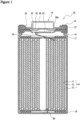
- FIG. 1 is an axial cross-sectional view of a cylindrical secondary battery 10 according to an example embodiment.
- an electrode assembly 14 and a non-aqueous electrolyte (not shown in drawing) are housed in an outer casing 15.
- the electrode assembly 14 has a spiral structure formed by winding a positive electrode 11 and a negative electrode 12 with an interposed separator 13.
- a side toward a sealing assembly 16 will be described as “upper”
- a side toward the bottom portion of the outer casing 15 will be described as "lower”.
- the interior of the secondary battery 10 is hermetically sealed.
- Insulation plates 17, 18 are provided above and below the electrode assembly 14, respectively.
- a positive electrode lead 19 extends upward through a through hole in the insulation plate 17, and is welded to a lower surface of a filter 22, which is the bottom plate of the sealing assembly 16.
- a cap 26, which is the top plate of the sealing assembly 16 electrically connected to the filter 22 serves as the positive electrode terminal.
- a negative electrode lead 20 passes through a through hole in the insulation plate 18, extends toward the bottom portion of the outer casing 15, and is welded to the inner surface of the bottom portion of the outer casing 15.
- the outer casing 15 serves as the negative electrode terminal.
- the outer casing 15 is, for example, a bottomed cylindrical metal outer can.
- a gasket 27 is provided between the outer casing 15 and the sealing assembly 16, and hermetic sealing of the interior of the secondary battery 10 is thereby ensured.
- the outer casing 15 has a grooved portion 21 which is formed, for example, by pressing a side surface portion from outside.
- the grooved portion 21 is preferably formed in an annular shape along the circumferential direction of the outer casing 15, and supports the sealing assembly 16 on its upper surface via the gasket 27.
- the sealing assembly 16 comprises the filter 22, a lower valve member 23, an insulation member 24, an upper valve member 25, and the cap 26, which are stacked in this order from the electrode assembly 14 side.
- Each of the members constituting the sealing assembly 16 has, for example, a disk shape or a ring shape, and the respective members other than the insulation member 24 are electrically connected to each other.
- the lower valve member 23 and the upper valve member 25 are connected to each other at their central portions, and the insulation member 24 is interposed between peripheral edge portions of these valve members.
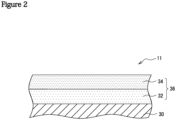
- FIG. 2 is a cross-sectional view of a positive electrode 11 according to an example embodiment.
- the positive electrode 11 comprises a positive electrode current collector 30, a first positive electrode mixture layer 32 formed on a surface of the positive electrode current collector 30, and a second positive electrode mixture layer 34 formed on a surface of the first positive electrode mixture layer 32.
- the first positive electrode mixture layer 32 and the second positive electrode mixture layer 34 may be collectively referred to as a positive electrode mixture layer 36.
- the positive electrode current collector 30 it is possible to use a foil of a metal such as aluminum that is stable in the potential range of the positive electrode, a film having such a metal disposed on its surface layer, and the like.
- the thickness of the positive electrode current collector 30 is, for example, 10 ⁇ m to 30 ⁇ m.
- the positive electrode mixture layer 36 is preferably formed on both sides of the positive electrode current collector 30.
- the thickness of the positive electrode mixture layer 36 on one side of the positive electrode current collector 30 is preferably 50 ⁇ m to 200 ⁇ m, and more preferably 70 ⁇ m to 150 ⁇ m.
- the positive electrode mixture layer 36 contains, for example, a positive electrode active material, a conductive agent, and a binder.
- Examples of the conductive agent contained in the positive electrode mixture layer 36 include carbon-based particles such as carbon black (CB), acetylene black (AB), Ketjen black, carbon nanotubes (CNT), graphene, and graphite. These may be used alone or by combining two or more thereof.
- binder contained in the positive electrode mixture layer 36 examples include fluororesins such as polytetrafluoroethylene (PTFE) and polyvinylidene fluoride (PVDF), polyacrylonitrile (PAN), polyimide resins, acrylic resins, and polyolefin resins. A single type among these may be used alone, or two or more types may be used in combination.
- fluororesins such as polytetrafluoroethylene (PTFE) and polyvinylidene fluoride (PVDF), polyacrylonitrile (PAN), polyimide resins, acrylic resins, and polyolefin resins.
- PTFE polytetrafluoroethylene
- PVDF polyvinylidene fluoride
- PAN polyacrylonitrile
- polyimide resins acrylic resins
- acrylic resins acrylic resins
- polyolefin resins A single type among these may be used alone, or two or more types may be used in combination.
- the positive electrode active material contained in the positive electrode mixture layer 36 is different between the first positive electrode mixture layer 32 and the second positive electrode mixture layer 34. That is, the first positive electrode mixture layer 32 contains a first positive electrode active material, and the second positive electrode mixture layer 34 contains a second positive electrode active material. It is noted that so long as the object of the present disclosure is not impaired, the first positive electrode mixture layer 32 may contain a positive electrode active material other than the first positive electrode active material, and the second positive electrode mixture layer 34 may contain a positive electrode active material other than the second positive electrode active material.
- the letter “a” denoting the number of moles of Li per 1 mole of the first positive electrode active material and the letter “f' denoting the number of moles of Li per 1 mole of the second positive electrode active material are both 0.9 to 1.2, preferably 0.95 to 1.05, and more preferably 1.
- the battery capacity may be lower than when “a” is within the above range.
- the charge-discharge cycle characteristic may be deteriorated compared to when "a” is within the above range.
- the battery capacity in a battery containing a positive electrode active material with a high Ni content tends to become reduced due to repeated charging and discharging.
- the positive electrode mixture layer By forming the positive electrode mixture layer to have a laminate structure and to be configured such that the second positive electrode active material with a Ni content lower than that of the first positive electrode active material is arranged on the surface side in contact with the electrolyte, the safety and the cycle characteristic can be improved. Further, by setting "g" to 0.80 or more, a high-capacity battery can be obtained.
- the letter “c”, which indicates the ratio of M1 to the total number of moles of metal elements other than Li in the first positive electrode active material, is 0 to 0.10, preferably 0.03 to 0.10, and more preferably 0.05 to 0.10.
- the letter “h”, which indicates the ratio of M3 to the total number of moles of metal elements other than Li in the second positive electrode active material is 0 to 0.20, preferably 0.05 to 0.20, and more preferably 0.10 to 0.20.
- Each of M1 and M3 is one or more elements selected from the group consisting of Co, Al, and Mn. Since Co has high electron conductivity, Co can reduce resistance. Al and Mn can stabilize the crystal structure of the positive electrode active material.
- M1 and M3 may be elements different from each other, but are preferably the same element(s). Both M1 and M3 may include Co and Al.
- the letter “d”, which indicates the ratio of M2 to the total number of moles of metal elements other than Li in the first positive electrode active material, and the letter “i”, which indicates the ratio of M4 to the total number of moles of metal elements other than Li in the second positive electrode active material, are both 0 to 0.05, preferably 0 to 0.03, and more preferably 0.
- Each of M2 and M4 is one or more elements selected from the group consisting of Ti, Mg, and Zr.
- M2 and M4 may be elements different from each other, or may be the same element(s).
- the thickness ratio of the first positive electrode mixture layer 32 to the second positive electrode mixture layer 34 is preferably 90:10 to 60:40. With this feature, the battery capacity can be further increased while improving the battery's thermal stability and cycle characteristic in a high-temperature environment.
- the content of the first positive electrode active material in the first positive electrode mixture layer 32 is, for example, 90 % by mass to 99 % by mass, and preferably 95 % by mass to 99 % by mass, relative to the total mass of the first positive electrode mixture layer 32.
- the positive electrode 11 with a positive electrode mixture layer having a two-layer structure as shown in FIG. 2 can be produced by: separately preparing a first positive electrode mixture slurry containing a positive electrode active material, a conductive agent, and a binder, and a second positive electrode mixture slurry containing a positive electrode active material, a conductive agent, and a binder; applying the first positive electrode mixture slurry onto both sides of the positive electrode current collector 30 and carrying out drying; applying on top thereof the second positive electrode mixture slurry and carrying out drying; and then rolling the applied coating with a roller.
- the second positive electrode mixture slurry may be applied on top thereof, and then drying may be carried out.
- the negative electrode 12 comprises a negative electrode current collector and a negative electrode mixture layer formed on a surface of the negative electrode current collector.
- the negative electrode current collector it is possible to use a foil of a metal such as copper that is stable in the potential range of the negative electrode, a film having such a metal disposed on its surface layer, and the like.
- the thickness of the negative electrode current collector is, for example, 5 ⁇ m to 30 ⁇ m.
- the negative electrode mixture layer is preferably formed on both sides of the negative electrode current collector.
- the thickness of the negative electrode mixture layer on one side of the negative electrode current collector is, for example, 10 ⁇ m to 150 ⁇ m.
- the negative electrode mixture layer contains, for example, a negative electrode active material and a binder.
- the negative electrode can be produced, for example, by applying a negative electrode mixture slurry containing the negative electrode active material, the binder, and the like onto both sides of the negative electrode current collector, drying the applied coating, and then rolling the applied coating using a roller.
- the negative electrode active material contained in the negative electrode mixture layer so long as the negative electrode active material can reversibly occlude and release lithium ions, and a carbon material such as graphite is generally used therefor.
- the graphite may be either natural graphite such as flake graphite, massive graphite, and earthy graphite, or artificial graphite such as massive artificial graphite and graphitized mesophase carbon microbeads.
- the negative electrode active material it is possible to use a metal that forms an alloy with Li such as Si or Sn, a metal compound containing Si, Sn, or the like, a lithium titanium composite oxide, and so on.
- a Si-containing compound represented by SiO x (where 0.5 ⁇ x ⁇ 1.6)
- a Si-containing compound in which fine particles of Si are dispersed in a lithium silicate phase represented by Li 2y SiO (2+y) (where 0 ⁇ y ⁇ 2), or the like may be used.
- binder contained in the negative electrode mixture layer examples include styrene-butadiene rubber (SBR), nitrile-butadiene rubber (NBR), carboxymethyl cellulose (CMC) or a salt thereof, polyacrylic acid (PAA) or a salt thereof (which may be PAA-Na, PAA-K, or the like, or a partially neutralized salt), and polyvinyl alcohol (PVA).
- SBR styrene-butadiene rubber
- NBR nitrile-butadiene rubber
- CMC carboxymethyl cellulose
- PAA polyacrylic acid
- PVA polyvinyl alcohol
- a single type among these may be used alone, or two or more types may be used in combination.
- the separator 13 isolates the positive electrode 11 and negative electrode 12 from each other.
- a porous sheet having ion permeability and insulation property is used as the separator 13.
- the porous sheet include a microporous film, woven fabric, and non-woven fabric.
- olefin resins such as polyethylene and polypropylene, cellulose, and the like are suitable.
- the separator 13 may be a laminate having a cellulose fiber layer and a layer of thermoplastic resin fibers made of olefin resin or the like. Further, the separator may be a multilayer separator including a polyethylene layer and a polypropylene layer. It is also possible to use a separator 13 having a surface coated with a material such as aramid resin or ceramic.
- the non-aqueous electrolyte may contain a non-aqueous solvent and an electrolyte salt dissolved in the non-aqueous solvent.
- a non-aqueous solvent it is possible to use, for example, esters, ethers, nitriles such as acetonitrile, amides such as dimethylformamide, a mixed solvent containing two or more of the foregoing, and the like.
- the non-aqueous solvent may contain a halogen-substituted product obtained by substituting at least part of hydrogens in the above solvents with halogen atoms such as fluorine.
- halogen-substituted product examples include fluorinated cyclic carbonate esters such as fluoroethylene carbonate (FEC), fluorinated chain carbonate esters, fluorinated chain carboxylate esters such as methyl fluoropropionate (FMP), and the like.
- FEC fluoroethylene carbonate
- FMP fluorinated chain carboxylate esters
- FEC fluoroethylene carbonate
- FMP fluorinated chain carboxylate esters
- esters examples include: cyclic carbonate esters such as ethylene carbonate (EC), propylene carbonate (PC), and butylene carbonate; chain carbonate esters such as dimethyl carbonate (DMC), ethyl methyl carbonate (EMC), diethyl carbonate (DEC), methyl propyl carbonate, ethyl propyl carbonate, and methyl isopropyl carbonate; cyclic carboxylate esters such as ⁇ -butyrolactone (GBL) and ⁇ -valerolactone (GVL); and chain carboxylate esters such as methyl acetate, ethyl acetate, propyl acetate, methyl propionate (MP), and ethyl propionate.
- cyclic carbonate esters such as ethylene carbonate (EC), propylene carbonate (PC), and butylene carbonate
- chain carbonate esters such as dimethyl carbonate (DMC), ethyl methyl carbonate (EMC), diethyl
- ethers examples include: cyclic ethers such as 1,3-dioxolane, 4-methyl-1,3-dioxolane, tetrahydrofuran, 2-methyltetrahydrofran, propylene oxide, 1,2-butylene oxide, 1,3-dioxane, 1,4-dioxane, 1,3,5-trioxane, furan, 2-methylfuran, 1,8-cineole, and crown ethers; and chain ethers such as 1,2-dimethoxyethane, diethyl ether, dipropyl ether, diisopropyl ether, dibutyl ether, dihexyl ether, ethyl vinyl ether, butyl vinyl ether, methyl phenyl ether, ethyl phenyl ether, butyl phenyl ether, pentyl phenyl ether, methoxy toluene, benzyl ethyl
- the electrolyte salt is preferably lithium salt.
- lithium salt include LiBF 4 , LiClO 4 , LiPF 6 , LiAsF 6 , LiSbF 6 , LiAlCl 4 , LiSCN, LiCF 3 SO 3 , LiCF 3 CO 2 , Li(P(C 2 O 4 )F 4 ), LiPF 6-x (C n F 2n+1 ) x (where 1 ⁇ x ⁇ 6, and n is 1 or 2), LiB 10 Cl 10 , LiCl, LiBr, LiI, chloroborane lithium, lower aliphatic lithium carboxylate, borates such as Li 2 B 4 O 7 and Li(B(C 2 O 4 )F 2 ), and imide salts such as LiN(SO 2 CF 3 ) 2 and LiN(C 1 F 2l+1 SO 2 )(C m F 2m+1 SO 2 ) (where each of 1 and m is an integer of 0 or greater).
- the lithium salt a single type among the above may be used alone, or a plurality of types may be mixed and used. Among the foregoing, it is preferable to use LiPF 6 in consideration of ion conductivity, electrochemical stability, and the like.
- the concentration of the lithium salt is preferably 0.8 mol to 1.8 mol per 1 liter of the non-aqueous solvent.
- the first positive electrode active material a lithium transition metal composite oxide represented by LiNi 0.91 Co 0.06 Al 0.03 O 2 was used.
- a first positive electrode mixture slurry was prepared by mixing the first positive electrode active material, acetylene black (AB), and polyvinylidene fluoride (PVDF) at a mass ratio of 100:1:0.9, and kneading the mixture while adding N-methyl pyrrolidone (NMP).
- NMP N-methyl pyrrolidone
- the first positive electrode mixture slurry was applied using a doctor blade method onto both sides of a positive electrode current collector made of aluminum foil having a thickness of 15 ⁇ m, and the applied coating was dried to thereby form a first positive electrode mixture layer (in an uncompressed state).
- the second positive electrode active material a lithium transition metal composite oxide represented by LiNi 0.88 Co 0.09 Al 0.03 O 2 was used.
- a second positive electrode mixture slurry was prepared by mixing the second positive electrode active material, acetylene black (AB), and polyvinylidene fluoride (PVDF) at a mass ratio of 100:1:0.9, and kneading the mixture while adding N-methyl pyrrolidone (NMP).
- NMP N-methyl pyrrolidone
- the second positive electrode mixture slurry was applied using a doctor blade method onto both sides of the first positive electrode mixture layer, and the applied coating was dried to thereby form a second positive electrode mixture layer laminated on the entire surface of the first positive electrode mixture layer.
- the product After rolling the first positive electrode mixture layer and the second positive electrode mixture layer using a roller, the product was cut into a predetermined electrode size, and a positive electrode was thereby produced. After the rolling, the ratio between the thickness of the first positive electrode mixture layer and the thickness of the second positive electrode mixture layer was 25:75. Further, at a part of the positive electrode, there was provided an exposed portion where the positive electrode current collector was exposed, and an aluminum positive electrode lead was attached to the exposed portion.
- a negative electrode mixture slurry was prepared by kneading the negative electrode active material, carboxymethyl cellulose (CMC), and styrene-butadiene rubber (SBR) in water such that their mass ratio was 100:1:1.
- CMC carboxymethyl cellulose
- SBR styrene-butadiene rubber
- the negative electrode mixture slurry was applied using a doctor blade method onto both sides of a negative electrode current collector made of copper foil, and after drying, the coating was rolled with a roller. The product was cut into a predetermined electrode size, and a negative electrode was thereby produced. Further, at a part of the negative electrode, there was provided an exposed portion where a surface of the negative electrode current collector was exposed, and a nickel negative electrode lead was attached to the exposed portion.
- EC ethylene carbonate
- DMC dimethyl carbonate
- LiPF 6 lithium hexafluorophosphate
- a spiral-type electrode assembly was produced by spirally winding the positive electrode and the negative electrode with an interposed separator made of polyethylene film having a thickness of 12 ⁇ m. This electrode assembly was placed in a bottomed cylindrical outer casing, and the negative electrode lead was welded to the bottom portion of the outer casing. Next, the positive electrode lead was welded to a sealing assembly, and after injection of the above non-aqueous electrolyte, the opening of the outer casing was sealed with the sealing assembly, and a secondary battery was thereby obtained.
- the above secondary battery was charged at a constant current of 1380 mA until reaching 4.2 V, and then charged at a constant voltage of 4.2V until reaching 92 mA. Subsequently, the secondary battery was placed in a thermostatic chamber. The temperature of the thermostatic chamber was increased from 25 °C to 135 °C at a rate of 5 °C/min, and the temperature of a side portion of the secondary battery was measured with a thermocouple. Based on the maximum temperature reached by the secondary battery at that time, the safety of the secondary battery was evaluated.
- a secondary battery was produced and evaluated in the same manner as in Example 1 except that, in the production of the positive electrode, a lithium transition metal composite oxide represented by LiNi 0.82 Co 0.15 Al 0.03 O 2 was used as the second positive electrode active material.
- a secondary battery was produced and evaluated in the same manner as in Example 1 except that, in the production of the positive electrode, a lithium transition metal composite oxide represented by LiNi 0.88 Co 0.09 Al 0.03 O 2 was used as the first positive electrode active material, and a lithium transition metal composite oxide represented by LiNi 0.91 Co 0.06 Al 0.03 O 2 was used as the second positive electrode active material.
- a secondary battery was produced and evaluated in the same manner as in Example 1 except that, in the production of the positive electrode, a lithium transition metal composite oxide represented by LiNi 0.82 Co 0.15 Al 0.03 O 2 was used as the first positive electrode active material, and a lithium transition metal composite oxide represented by LiNi 0.91 Co 0.06 Al 0.03 O 2 was used as the second positive electrode active material.
- a secondary battery was produced and evaluated in the same manner as in Example 1 except that, in the production of the positive electrode, a lithium transition metal composite oxide represented by LiNi 0.91 Co 0.06 Al 0.03 O 2 was used as the second positive electrode active material.
- a secondary battery was produced and evaluated in the same manner as in Example 1 except that, in the production of the positive electrode, a lithium transition metal composite oxide represented by LiNi 0.88 Co 0.09 Al 0.03 O 2 was used as the first positive electrode active material.
- a secondary battery was produced and evaluated in the same manner as in Example 1 except that, in the production of the positive electrode, a lithium transition metal composite oxide represented by LiNi 0.82 Co 0.15 Al 0.03 O 2 was used as the first positive electrode active material and the second positive electrode active material.
- Table 1 shows the evaluation results for each of the secondary batteries of the Examples and Comparative Examples. Table 1 also shows the values of Ni content in the first positive electrode mixture layer and in the second positive electrode mixture layer, and the thickness ratio of the first positive electrode mixture layer to the second positive electrode mixture layer.
- the secondary batteries of the Examples had excellent battery characteristics (i.e., battery capacity and cycle characteristic) and a high level of safety (i.e., thermal stability).
- the cycle characteristic and the thermal stability were less favorable than in the secondary batteries of the Examples.
- the battery capacity, in addition to the cycle characteristic and the thermal stability was less favorable than in the secondary batteries of the Examples.
- the secondary batteries of Comparative Examples 3 to 5 in which the values of Ni content in the first positive electrode active material and in the second positive electrode mixture layer were equal, either the battery characteristics or the level of safety was less favorable than in the Examples.
- 10 secondary battery 11 positive electrode; 12 negative electrode; 13 separator; 14 electrode assembly; 15 outer casing; 16 sealing assembly; 17, 18 insulation plate; 19 positive electrode lead; 20 negative electrode lead; 21 grooved portion; 22 filter; 23 lower valve member; 24 insulation member; 25 upper valve member; 26 cap; 26a opening; 27 gasket; 30 positive electrode current collector; 32 first positive electrode mixture layer; 34 second positive electrode mixture layer; 36 positive electrode mixture layer.
Landscapes
- Chemical & Material Sciences (AREA)
- Chemical Kinetics & Catalysis (AREA)
- Electrochemistry (AREA)
- General Chemical & Material Sciences (AREA)
- Composite Materials (AREA)
- Engineering & Computer Science (AREA)
- Inorganic Chemistry (AREA)
- Materials Engineering (AREA)
- Manufacturing & Machinery (AREA)
- Battery Electrode And Active Subsutance (AREA)
- Secondary Cells (AREA)
Abstract
Description
- The present disclosure relates to a non-aqueous electrolyte secondary battery.
- In recent years, lithium-containing composite oxides containing Ni have attracted attention as positive electrode active materials with high energy density. When a lithium-containing composite oxide with a high Ni content is used, the battery capacity increases, but the battery temperature may become increased at times of abnormality. Patent Literature 1 discloses a technique of suppressing an increase in the temperature of a battery upon nail penetration by using a positive electrode in which, between a positive electrode current collector and a first layer containing a lithium-containing composite oxide with a Ni content of 70 % or less, there is formed a second layer containing a lithium-containing composite oxide with a Ni content of 50 % or less.
- PATENT LITERATURE 1:
Japanese Unexamined Patent Application Publication No. 2019-140039 - A lithium-containing composite oxide with a high Ni content tends to produce a large amount of self-generated heat in a high-temperature environment, and its use involves an issue of improving the thermal stability. Further, in a lithium-containing composite oxide with a high Ni content, a large amount of Li is extracted during charging, and the layered crystal structure tends to be easily broken. Accordingly, when a lithium-containing composite oxide with a high Ni content is used, the battery capacity tends to be decreased due to repeated charging and discharging. This tendency is particularly noticeable in a high-temperature environment. In the technique disclosed in Patent Literature 1, no consideration has been made regarding the thermal stability or regarding deterioration of the cycle characteristic in a high-temperature environment, and there is still room for improvement.
- An object of the present disclosure is to provide a non-aqueous electrolyte secondary battery having a high level of safety and excellent battery characteristics.
- A non-aqueous electrolyte secondary battery according to an aspect of the present disclosure includes a positive electrode, a negative electrode, a separator that isolates the positive electrode and the negative electrode from each other, and a non-aqueous electrolyte. The positive electrode has a positive electrode current collector, a first positive electrode mixture layer formed on a surface of the positive electrode current collector, and a second positive electrode mixture layer formed on a surface of the first positive electrode mixture layer. The first positive electrode mixture layer contains a first positive electrode active material represented by general formula LiaNibM1cM2dOe (where 0.9 ≤ a ≤ 1.2, 0.90 ≤ b ≤ 0.95, 0 ≤ c ≤ 0.10, 0 ≤ d ≤ 0.05, 1.9 ≤ e ≤ 2.1, b+c+d = 1, M1 is one or more elements selected from the group consisting of Co, Al, and Mn, and M2 is one or more elements selected from the group consisting of Ti, Mg, and Zr). The second positive electrode mixture layer contains a second positive electrode active material represented by general formula LifNigM3hM4iOj (where 0.9 ≤ f ≤ 1.2, 0.80 ≤ g ≤ 0.90, 0 ≤ h ≤ 0.20, 0 ≤ i ≤ 0.05, 1.9 ≤ j ≤ 2.1, g+h+i = 1, M3 is one or more elements selected from the group consisting of Co, Al, and Mn, and M4 is one or more elements selected from the group consisting of Ti, Mg, and Zr), and g and b satisfy g < b.
- According to the non-aqueous electrolyte secondary battery according to the present disclosure, safety and battery characteristics can be improved.
-
- [
FIG. 1] FIG. 1 is an axial cross-sectional view of a non-aqueous electrolyte secondary battery according to an example embodiment. - [
FIG. 2] FIG. 2 is a cross-sectional view of a positive electrode according to an example embodiment. - An example embodiment of a non-aqueous electrolyte secondary battery according to the present disclosure will now be described in detail by reference to the drawings. Although a cylindrical battery in which a spiral-type electrode assembly is housed in a cylindrical outer casing is described below as an example, the outer casing is not limited to being cylindrical, and may be, for example, rectangular, coin-shaped, or the like, or may be a pouch-shaped casing composed of a laminate sheet including a metal layer and a resin layer. Further, the electrode assembly may be a laminate-type electrode assembly formed by alternately laminating a plurality of positive electrodes and a plurality of negative electrodes via separators. In the present specification, the expression "numerical value (A) to numerical value (B)" means greater than or equal to numerical value (A) and less than or equal to numerical value (B).
-
FIG. 1 is an axial cross-sectional view of a cylindricalsecondary battery 10 according to an example embodiment. In thesecondary battery 10 shown inFIG. 1 , anelectrode assembly 14 and a non-aqueous electrolyte (not shown in drawing) are housed in anouter casing 15. Theelectrode assembly 14 has a spiral structure formed by winding apositive electrode 11 and anegative electrode 12 with an interposedseparator 13. In the following, for convenience of explanation, a side toward asealing assembly 16 will be described as "upper", and a side toward the bottom portion of theouter casing 15 will be described as "lower". - By having an open end portion of the
outer casing 15 at its upper part being closed with thesealing assembly 16, the interior of thesecondary battery 10 is hermetically sealed.Insulation plates electrode assembly 14, respectively. Apositive electrode lead 19 extends upward through a through hole in theinsulation plate 17, and is welded to a lower surface of afilter 22, which is the bottom plate of thesealing assembly 16. In thesecondary battery 10, acap 26, which is the top plate of thesealing assembly 16 electrically connected to thefilter 22, serves as the positive electrode terminal. Further, a negative electrode lead 20 passes through a through hole in theinsulation plate 18, extends toward the bottom portion of theouter casing 15, and is welded to the inner surface of the bottom portion of theouter casing 15. In thesecondary battery 10, theouter casing 15 serves as the negative electrode terminal. - The
outer casing 15 is, for example, a bottomed cylindrical metal outer can. Agasket 27 is provided between theouter casing 15 and thesealing assembly 16, and hermetic sealing of the interior of thesecondary battery 10 is thereby ensured. Theouter casing 15 has agrooved portion 21 which is formed, for example, by pressing a side surface portion from outside. Thegrooved portion 21 is preferably formed in an annular shape along the circumferential direction of theouter casing 15, and supports thesealing assembly 16 on its upper surface via thegasket 27. - The
sealing assembly 16 comprises thefilter 22, alower valve member 23, aninsulation member 24, anupper valve member 25, and thecap 26, which are stacked in this order from theelectrode assembly 14 side. Each of the members constituting thesealing assembly 16 has, for example, a disk shape or a ring shape, and the respective members other than theinsulation member 24 are electrically connected to each other. Thelower valve member 23 and theupper valve member 25 are connected to each other at their central portions, and theinsulation member 24 is interposed between peripheral edge portions of these valve members. When the internal pressure of the battery increases due to abnormal heat generation, for example, thelower valve member 23 ruptures, and theupper valve member 25 is thereby caused to swell toward thecap 26 side and separate from thelower valve member 23, so that electrical connection between the two valve members is cut off. When the internal pressure increases further, theupper valve member 25 ruptures, and gas is discharged from an opening 26a in thecap 26. - A detailed description will be given below regarding the
positive electrode 11, thenegative electrode 12, theseparator 13, and the non-aqueous electrolyte which constitute thesecondary battery 10, and especially regarding thepositive electrode 11. - The configuration of the
positive electrode 11 will now be described by reference toFIG. 2. FIG. 2 is a cross-sectional view of apositive electrode 11 according to an example embodiment. Thepositive electrode 11 comprises a positiveelectrode current collector 30, a first positiveelectrode mixture layer 32 formed on a surface of the positiveelectrode current collector 30, and a second positiveelectrode mixture layer 34 formed on a surface of the first positiveelectrode mixture layer 32. The first positiveelectrode mixture layer 32 and the second positiveelectrode mixture layer 34 may be collectively referred to as a positiveelectrode mixture layer 36. - As the positive electrode
current collector 30, it is possible to use a foil of a metal such as aluminum that is stable in the potential range of the positive electrode, a film having such a metal disposed on its surface layer, and the like. The thickness of the positive electrodecurrent collector 30 is, for example, 10 µm to 30 µm. - The positive
electrode mixture layer 36 is preferably formed on both sides of the positive electrodecurrent collector 30. The thickness of the positiveelectrode mixture layer 36 on one side of the positiveelectrode current collector 30 is preferably 50 µm to 200 µm, and more preferably 70 µm to 150 µm. The positiveelectrode mixture layer 36 contains, for example, a positive electrode active material, a conductive agent, and a binder. - Examples of the conductive agent contained in the positive
electrode mixture layer 36 include carbon-based particles such as carbon black (CB), acetylene black (AB), Ketjen black, carbon nanotubes (CNT), graphene, and graphite. These may be used alone or by combining two or more thereof. - Examples of the binder contained in the positive
electrode mixture layer 36 include fluororesins such as polytetrafluoroethylene (PTFE) and polyvinylidene fluoride (PVDF), polyacrylonitrile (PAN), polyimide resins, acrylic resins, and polyolefin resins. A single type among these may be used alone, or two or more types may be used in combination. - The positive electrode active material contained in the positive
electrode mixture layer 36 is different between the first positiveelectrode mixture layer 32 and the second positiveelectrode mixture layer 34. That is, the first positiveelectrode mixture layer 32 contains a first positive electrode active material, and the second positiveelectrode mixture layer 34 contains a second positive electrode active material. It is noted that so long as the object of the present disclosure is not impaired, the first positiveelectrode mixture layer 32 may contain a positive electrode active material other than the first positive electrode active material, and the second positiveelectrode mixture layer 34 may contain a positive electrode active material other than the second positive electrode active material. - The first positive electrode active material is represented by general formula LiaNibM1cM2dOe (where 0.9 ≤ a ≤ 1.2, 0.90 ≤ b ≤ 0.95, 0 ≤ c ≤ 0.10, 0 ≤ d ≤ 0.05, 1.9 ≤ e ≤ 2.1, b+c+d = 1, M1 is one or more elements selected from the group consisting of Co, Al, and Mn, and M2 is one or more elements selected from the group consisting of Ti, Mg, and Zr).
- The second positive electrode active material is represented by general formula LifNigM3hM4iOj (where 0.9 ≤ f ≤ 1.2, 0.80 ≤ g ≤ 0.90, 0 ≤ h ≤ 0.20, 0 ≤ i ≤ 0.05, 1.9 ≤ j ≤ 2.1, g+h+i = 1, M3 is one or more elements selected from the group consisting of Co, Al, and Mn, and M4 is one or more elements selected from the group consisting of Ti, Mg, and Zr).
- The letter "a" denoting the number of moles of Li per 1 mole of the first positive electrode active material and the letter "f' denoting the number of moles of Li per 1 mole of the second positive electrode active material are both 0.9 to 1.2, preferably 0.95 to 1.05, and more preferably 1. When "a" is less than 0.9, the battery capacity may be lower than when "a" is within the above range. When "a" is 1.2 or more, the charge-discharge cycle characteristic may be deteriorated compared to when "a" is within the above range.
- The letter "b", which indicates the ratio of Ni to the total number of moles of metal elements other than Li in the first positive electrode active material (hereinafter may be referred to as Ni content; the same applies to the second positive electrode active material), is 0.90 to 0.95. Further, the letter "g", which indicates the ratio of Ni to the total number of moles of metal elements other than Li in the second positive electrode active material, is 0.80 to 0.90, and g and b satisfy g < b. With these features, a
secondary battery 10 having a high level of safety and excellent battery characteristics can be obtained. Since the amount of self-generated heat in a positive electrode active material tends to increase with increasing Ni content, the temperature of a battery containing a positive electrode active material with a high Ni content may become increased. Further, since a positive electrode active material with a high Ni content tends to cause side reactions with the electrolyte, the battery capacity in a battery containing a positive electrode active material with a high Ni content tends to become reduced due to repeated charging and discharging. By forming the positive electrode mixture layer to have a laminate structure and to be configured such that the second positive electrode active material with a Ni content lower than that of the first positive electrode active material is arranged on the surface side in contact with the electrolyte, the safety and the cycle characteristic can be improved. Further, by setting "g" to 0.80 or more, a high-capacity battery can be obtained. - The letter "c", which indicates the ratio of M1 to the total number of moles of metal elements other than Li in the first positive electrode active material, is 0 to 0.10, preferably 0.03 to 0.10, and more preferably 0.05 to 0.10. Further, the letter "h", which indicates the ratio of M3 to the total number of moles of metal elements other than Li in the second positive electrode active material, is 0 to 0.20, preferably 0.05 to 0.20, and more preferably 0.10 to 0.20. Each of M1 and M3 is one or more elements selected from the group consisting of Co, Al, and Mn. Since Co has high electron conductivity, Co can reduce resistance. Al and Mn can stabilize the crystal structure of the positive electrode active material. M1 and M3 may be elements different from each other, but are preferably the same element(s). Both M1 and M3 may include Co and Al.
- The letter "d", which indicates the ratio of M2 to the total number of moles of metal elements other than Li in the first positive electrode active material, and the letter "i", which indicates the ratio of M4 to the total number of moles of metal elements other than Li in the second positive electrode active material, are both 0 to 0.05, preferably 0 to 0.03, and more preferably 0. Each of M2 and M4 is one or more elements selected from the group consisting of Ti, Mg, and Zr. M2 and M4 may be elements different from each other, or may be the same element(s).
- The thickness ratio of the first positive
electrode mixture layer 32 to the second positiveelectrode mixture layer 34 is preferably 90:10 to 60:40. With this feature, the battery capacity can be further increased while improving the battery's thermal stability and cycle characteristic in a high-temperature environment. - The content of the first positive electrode active material in the first positive
electrode mixture layer 32 is, for example, 90 % by mass to 99 % by mass, and preferably 95 % by mass to 99 % by mass, relative to the total mass of the first positiveelectrode mixture layer 32. - No particular limitation is imposed on the method for producing the
positive electrode 11. For example, thepositive electrode 11 with a positive electrode mixture layer having a two-layer structure as shown inFIG. 2 can be produced by: separately preparing a first positive electrode mixture slurry containing a positive electrode active material, a conductive agent, and a binder, and a second positive electrode mixture slurry containing a positive electrode active material, a conductive agent, and a binder; applying the first positive electrode mixture slurry onto both sides of the positive electrodecurrent collector 30 and carrying out drying; applying on top thereof the second positive electrode mixture slurry and carrying out drying; and then rolling the applied coating with a roller. Alternatively, after applying the first positive electrode mixture slurry, without carrying out drying, the second positive electrode mixture slurry may be applied on top thereof, and then drying may be carried out. - The
negative electrode 12 comprises a negative electrode current collector and a negative electrode mixture layer formed on a surface of the negative electrode current collector. As the negative electrode current collector, it is possible to use a foil of a metal such as copper that is stable in the potential range of the negative electrode, a film having such a metal disposed on its surface layer, and the like. The thickness of the negative electrode current collector is, for example, 5 µm to 30 µm. - The negative electrode mixture layer is preferably formed on both sides of the negative electrode current collector. The thickness of the negative electrode mixture layer on one side of the negative electrode current collector is, for example, 10 µm to 150 µm. The negative electrode mixture layer contains, for example, a negative electrode active material and a binder. The negative electrode can be produced, for example, by applying a negative electrode mixture slurry containing the negative electrode active material, the binder, and the like onto both sides of the negative electrode current collector, drying the applied coating, and then rolling the applied coating using a roller.
- No particular limitation is imposed on the negative electrode active material contained in the negative electrode mixture layer so long as the negative electrode active material can reversibly occlude and release lithium ions, and a carbon material such as graphite is generally used therefor. The graphite may be either natural graphite such as flake graphite, massive graphite, and earthy graphite, or artificial graphite such as massive artificial graphite and graphitized mesophase carbon microbeads. Further, as the negative electrode active material, it is possible to use a metal that forms an alloy with Li such as Si or Sn, a metal compound containing Si, Sn, or the like, a lithium titanium composite oxide, and so on. For example, in combination with graphite, a Si-containing compound represented by SiOx (where 0.5 ≤ x ≤ 1.6), a Si-containing compound in which fine particles of Si are dispersed in a lithium silicate phase represented by Li2ySiO(2+y) (where 0 < y < 2), or the like may be used.
- Examples of the binder contained in the negative electrode mixture layer include styrene-butadiene rubber (SBR), nitrile-butadiene rubber (NBR), carboxymethyl cellulose (CMC) or a salt thereof, polyacrylic acid (PAA) or a salt thereof (which may be PAA-Na, PAA-K, or the like, or a partially neutralized salt), and polyvinyl alcohol (PVA). A single type among these may be used alone, or two or more types may be used in combination.
- The
separator 13 isolates thepositive electrode 11 andnegative electrode 12 from each other. As theseparator 13, for example, a porous sheet having ion permeability and insulation property is used. Specific examples of the porous sheet include a microporous film, woven fabric, and non-woven fabric. As the material of the separator, olefin resins such as polyethylene and polypropylene, cellulose, and the like are suitable. Theseparator 13 may be a laminate having a cellulose fiber layer and a layer of thermoplastic resin fibers made of olefin resin or the like. Further, the separator may be a multilayer separator including a polyethylene layer and a polypropylene layer. It is also possible to use aseparator 13 having a surface coated with a material such as aramid resin or ceramic. - The non-aqueous electrolyte may contain a non-aqueous solvent and an electrolyte salt dissolved in the non-aqueous solvent. As the non-aqueous solvent, it is possible to use, for example, esters, ethers, nitriles such as acetonitrile, amides such as dimethylformamide, a mixed solvent containing two or more of the foregoing, and the like. The non-aqueous solvent may contain a halogen-substituted product obtained by substituting at least part of hydrogens in the above solvents with halogen atoms such as fluorine. Examples of the halogen-substituted product include fluorinated cyclic carbonate esters such as fluoroethylene carbonate (FEC), fluorinated chain carbonate esters, fluorinated chain carboxylate esters such as methyl fluoropropionate (FMP), and the like.
- Examples of the above-noted esters include: cyclic carbonate esters such as ethylene carbonate (EC), propylene carbonate (PC), and butylene carbonate; chain carbonate esters such as dimethyl carbonate (DMC), ethyl methyl carbonate (EMC), diethyl carbonate (DEC), methyl propyl carbonate, ethyl propyl carbonate, and methyl isopropyl carbonate; cyclic carboxylate esters such as γ-butyrolactone (GBL) and γ-valerolactone (GVL); and chain carboxylate esters such as methyl acetate, ethyl acetate, propyl acetate, methyl propionate (MP), and ethyl propionate.
- Examples of the above-noted ethers include: cyclic ethers such as 1,3-dioxolane, 4-methyl-1,3-dioxolane, tetrahydrofuran, 2-methyltetrahydrofran, propylene oxide, 1,2-butylene oxide, 1,3-dioxane, 1,4-dioxane, 1,3,5-trioxane, furan, 2-methylfuran, 1,8-cineole, and crown ethers; and chain ethers such as 1,2-dimethoxyethane, diethyl ether, dipropyl ether, diisopropyl ether, dibutyl ether, dihexyl ether, ethyl vinyl ether, butyl vinyl ether, methyl phenyl ether, ethyl phenyl ether, butyl phenyl ether, pentyl phenyl ether, methoxy toluene, benzyl ethyl ether, diphenyl ether, dibenzyl ether, o-dimethoxybenzene, 1,2-diethoxyethane, 1,2-dibutoxyethane, diethylene glycol dimethyl ether, diethylene glycol diethyl ether, diethylene glycol dibutyl ether, 1,1-dimethoxymethane, 1,1-diethoxyethane, triethylene glycol dimethyl ether, and tetraethylene glycol dimethyl ether.
- The electrolyte salt is preferably lithium salt. Examples of lithium salt include LiBF4, LiClO4, LiPF6, LiAsF6, LiSbF6, LiAlCl4, LiSCN, LiCF3SO3, LiCF3CO2, Li(P(C2O4)F4), LiPF6-x(CnF2n+1)x (where 1 < x < 6, and n is 1 or 2), LiB10Cl10, LiCl, LiBr, LiI, chloroborane lithium, lower aliphatic lithium carboxylate, borates such as Li2B4O7 and Li(B(C2O4)F2), and imide salts such as LiN(SO2CF3)2 and LiN(C1F2l+1SO2)(CmF2m+1SO2) (where each of 1 and m is an integer of 0 or greater). As the lithium salt, a single type among the above may be used alone, or a plurality of types may be mixed and used. Among the foregoing, it is preferable to use LiPF6 in consideration of ion conductivity, electrochemical stability, and the like. The concentration of the lithium salt is preferably 0.8 mol to 1.8 mol per 1 liter of the non-aqueous solvent.
- While the present disclosure will be further described below using Examples, the present disclosure is not limited to these Examples.
- As the first positive electrode active material, a lithium transition metal composite oxide represented by LiNi0.91Co0.06Al0.03O2 was used. A first positive electrode mixture slurry was prepared by mixing the first positive electrode active material, acetylene black (AB), and polyvinylidene fluoride (PVDF) at a mass ratio of 100:1:0.9, and kneading the mixture while adding N-methyl pyrrolidone (NMP). Next, the first positive electrode mixture slurry was applied using a doctor blade method onto both sides of a positive electrode current collector made of aluminum foil having a thickness of 15 µm, and the applied coating was dried to thereby form a first positive electrode mixture layer (in an uncompressed state).
- As the second positive electrode active material, a lithium transition metal composite oxide represented by LiNi0.88Co0.09Al0.03O2 was used. A second positive electrode mixture slurry was prepared by mixing the second positive electrode active material, acetylene black (AB), and polyvinylidene fluoride (PVDF) at a mass ratio of 100:1:0.9, and kneading the mixture while adding N-methyl pyrrolidone (NMP). Next, the second positive electrode mixture slurry was applied using a doctor blade method onto both sides of the first positive electrode mixture layer, and the applied coating was dried to thereby form a second positive electrode mixture layer laminated on the entire surface of the first positive electrode mixture layer. After rolling the first positive electrode mixture layer and the second positive electrode mixture layer using a roller, the product was cut into a predetermined electrode size, and a positive electrode was thereby produced. After the rolling, the ratio between the thickness of the first positive electrode mixture layer and the thickness of the second positive electrode mixture layer was 25:75. Further, at a part of the positive electrode, there was provided an exposed portion where the positive electrode current collector was exposed, and an aluminum positive electrode lead was attached to the exposed portion.
- 95 parts by mass of graphite and 5 parts by mass of SiO were mixed, and this mixture was used as the negative electrode active material. A negative electrode mixture slurry was prepared by kneading the negative electrode active material, carboxymethyl cellulose (CMC), and styrene-butadiene rubber (SBR) in water such that their mass ratio was 100:1:1. Next, the negative electrode mixture slurry was applied using a doctor blade method onto both sides of a negative electrode current collector made of copper foil, and after drying, the coating was rolled with a roller. The product was cut into a predetermined electrode size, and a negative electrode was thereby produced. Further, at a part of the negative electrode, there was provided an exposed portion where a surface of the negative electrode current collector was exposed, and a nickel negative electrode lead was attached to the exposed portion.
- Into a mixed solvent obtained by mixing ethylene carbonate (EC) and dimethyl carbonate (DMC) at a volume ratio of 1:3, lithium hexafluorophosphate (LiPF6) was dissolved at a concentration of 1.5 mol/L. Further, vinylene carbonate (VC) was dissolved into the above mixed solvent at a concentration of 5 % by mass, and a non-aqueous electrolyte (or electrolyte solution) was thereby prepared.
- A spiral-type electrode assembly was produced by spirally winding the positive electrode and the negative electrode with an interposed separator made of polyethylene film having a thickness of 12 µm. This electrode assembly was placed in a bottomed cylindrical outer casing, and the negative electrode lead was welded to the bottom portion of the outer casing. Next, the positive electrode lead was welded to a sealing assembly, and after injection of the above non-aqueous electrolyte, the opening of the outer casing was sealed with the sealing assembly, and a secondary battery was thereby obtained.
- In an ambient temperature of 45 °C, the above secondary battery was charged at a constant current of 1380 mA until reaching 4.2 V, and then charged at a constant voltage of 4.2V until reaching 92 mA. Subsequently, discharging was performed at a constant current of 2300 mA until reaching 2.5 V. Using this charging and discharging process as one cycle, 200 cycles were carried out, and the capacity retention rate was determined by the following formula. Further, the discharge capacity in the first cycle was regarded as the battery capacity.
Capacity retention rate = (Discharge capacity in the 200th cycle / Discharge capacity in the 1st cycle) × 100 - In an ambient temperature of 25 °C, the above secondary battery was charged at a constant current of 1380 mA until reaching 4.2 V, and then charged at a constant voltage of 4.2V until reaching 92 mA. Subsequently, the secondary battery was placed in a thermostatic chamber. The temperature of the thermostatic chamber was increased from 25 °C to 135 °C at a rate of 5 °C/min, and the temperature of a side portion of the secondary battery was measured with a thermocouple. Based on the maximum temperature reached by the secondary battery at that time, the safety of the secondary battery was evaluated.
- A secondary battery was produced and evaluated in the same manner as in Example 1 except that, in the production of the positive electrode, a lithium transition metal composite oxide represented by LiNi0.82Co0.15Al0.03O2 was used as the second positive electrode active material.
- A secondary battery was produced and evaluated in the same manner as in Example 1 except that, in the production of the positive electrode, a lithium transition metal composite oxide represented by LiNi0.88Co0.09Al0.03O2 was used as the first positive electrode active material, and a lithium transition metal composite oxide represented by LiNi0.91Co0.06Al0.03O2 was used as the second positive electrode active material.
- A secondary battery was produced and evaluated in the same manner as in Example 1 except that, in the production of the positive electrode, a lithium transition metal composite oxide represented by LiNi0.82Co0.15Al0.03O2 was used as the first positive electrode active material, and a lithium transition metal composite oxide represented by LiNi0.91Co0.06Al0.03O2 was used as the second positive electrode active material.
- A secondary battery was produced and evaluated in the same manner as in Example 1 except that, in the production of the positive electrode, a lithium transition metal composite oxide represented by LiNi0.91Co0.06Al0.03O2 was used as the second positive electrode active material.
- A secondary battery was produced and evaluated in the same manner as in Example 1 except that, in the production of the positive electrode, a lithium transition metal composite oxide represented by LiNi0.88Co0.09Al0.03O2 was used as the first positive electrode active material.
- A secondary battery was produced and evaluated in the same manner as in Example 1 except that, in the production of the positive electrode, a lithium transition metal composite oxide represented by LiNi0.82Co0.15Al0.03O2 was used as the first positive electrode active material and the second positive electrode active material.
- Table 1 shows the evaluation results for each of the secondary batteries of the Examples and Comparative Examples. Table 1 also shows the values of Ni content in the first positive electrode mixture layer and in the second positive electrode mixture layer, and the thickness ratio of the first positive electrode mixture layer to the second positive electrode mixture layer.
[Table 1] Positive electrode Battery characteristics Safety Ni content in 1st mixture layer [%] Ni content in 2nd mixture layer [%] Thickness ratio 1st mixture layer : 2nd mixture layer Battery capacity [mAh] Capacity retention rate [%] Maximum temperature reached [°C] Example 1 91 88 75:25 4594 88 137 Example 2 91 82 75:25 4577 90 135 Comparative Example 1 88 91 75:25 4583 87 140 Comparative Example 2 82 91 75:25 4531 87 140 Comparative Example 3 91 91 75:25 4600 86 140 Comparative Example 4 88 88 75:25 4577 87 137 Comparative Example 5 82 82 75:25 4508 90 135 - The secondary batteries of the Examples had excellent battery characteristics (i.e., battery capacity and cycle characteristic) and a high level of safety (i.e., thermal stability). On the other hand, in the secondary battery of Comparative Example 1 in which the Ni content in the second positive electrode active material was higher than the Ni content in the first positive electrode active material, the cycle characteristic and the thermal stability were less favorable than in the secondary batteries of the Examples. Further, in the Comparative Examples in which the Ni content in the first positive electrode active material was lower than that in Comparative Example 1, the battery capacity, in addition to the cycle characteristic and the thermal stability, was less favorable than in the secondary batteries of the Examples. In the secondary batteries of Comparative Examples 3 to 5 in which the values of Ni content in the first positive electrode active material and in the second positive electrode mixture layer were equal, either the battery characteristics or the level of safety was less favorable than in the Examples.
- 10 secondary battery; 11 positive electrode; 12 negative electrode; 13 separator; 14 electrode assembly; 15 outer casing; 16 sealing assembly; 17, 18 insulation plate; 19 positive electrode lead; 20 negative electrode lead; 21 grooved portion; 22 filter; 23 lower valve member; 24 insulation member; 25 upper valve member; 26 cap; 26a opening; 27 gasket; 30 positive electrode current collector; 32 first positive electrode mixture layer; 34 second positive electrode mixture layer; 36 positive electrode mixture layer.
Claims (2)
- A non-aqueous electrolyte secondary battery, comprising a positive electrode, a negative electrode, a separator that isolates the positive electrode and the negative electrode from each other, and a non-aqueous electrolyte, whereinthe positive electrode comprises a positive electrode current collector, a first positive electrode mixture layer formed on a surface of the positive electrode current collector, and a second positive electrode mixture layer formed on a surface of the first positive electrode mixture layer,the first positive electrode mixture layer contains a first positive electrode active material represented by general formula LiaNibM1cM2dOe (where 0.9 ≤ a ≤ 1.2, 0.90 ≤ b ≤ 0.95, 0 ≤ c ≤ 0.10, 0 ≤ d ≤ 0.05, 1.9 ≤ e ≤ 2.1, b+c+d = 1, M1 is one or more elements selected from the group consisting of Co, Al, and Mn, and M2 is one or more elements selected from the group consisting of Ti, Mg, and Zr),the second positive electrode mixture layer contains a second positive electrode active material represented by general formula LifNigM3hM4iOj (where 0.9 ≤ f ≤ 1.2, 0.80 ≤ g ≤ 0.90, 0 ≤ h ≤ 0.20, 0 ≤ i ≤ 0.05, 1.9 ≤ j ≤ 2.1, g+h+i = 1, M3 is one or more elements selected from the group consisting of Co, Al, and Mn, and M4 is one or more elements selected from the group consisting of Ti, Mg, and Zr), andg and b satisfy g < b.
- The non-aqueous electrolyte secondary battery according to claim 1, wherein a thickness ratio of the first positive electrode mixture layer to the second positive electrode mixture layer is 90:10 to 60:40.
Applications Claiming Priority (2)
| Application Number | Priority Date | Filing Date | Title |
|---|---|---|---|
| JP2021157967 | 2021-09-28 | ||
| PCT/JP2022/025079 WO2023053625A1 (en) | 2021-09-28 | 2022-06-23 | Nonaqueous electrolyte secondary battery |
Publications (2)
| Publication Number | Publication Date |
|---|---|
| EP4411861A1 true EP4411861A1 (en) | 2024-08-07 |
| EP4411861A4 EP4411861A4 (en) | 2025-06-04 |
Family
ID=85780579
Family Applications (1)
| Application Number | Title | Priority Date | Filing Date |
|---|---|---|---|
| EP22875504.7A Pending EP4411861A4 (en) | 2021-09-28 | 2022-06-23 | Nonaqueous electrolyte secondary battery |
Country Status (5)
| Country | Link |
|---|---|
| US (1) | US20240290960A1 (en) |
| EP (1) | EP4411861A4 (en) |
| JP (1) | JP7821191B2 (en) |
| CN (1) | CN117999665A (en) |
| WO (1) | WO2023053625A1 (en) |
Families Citing this family (1)
| Publication number | Priority date | Publication date | Assignee | Title |
|---|---|---|---|---|
| CN116960364A (en) * | 2023-09-21 | 2023-10-27 | 宁德时代新能源科技股份有限公司 | Positive electrode current collector, positive electrode plate, battery cell, battery and electrical device |
Family Cites Families (6)
| Publication number | Priority date | Publication date | Assignee | Title |
|---|---|---|---|---|
| JP5475611B2 (en) * | 2010-10-05 | 2014-04-16 | 株式会社日立製作所 | Lithium ion secondary battery |
| JP6773059B2 (en) | 2018-02-14 | 2020-10-21 | トヨタ自動車株式会社 | Non-aqueous electrolyte secondary battery |
| CN113906586B (en) * | 2019-05-24 | 2024-10-18 | 三星Sdi株式会社 | Positive electrode for lithium secondary battery, method for manufacturing the same, and lithium secondary battery including the positive electrode |
| KR102835553B1 (en) * | 2019-09-10 | 2025-07-17 | 주식회사 엘지에너지솔루션 | Cathode for lithium secondary battery, manufacturuing method thereof and lithium secondary battery comprising the same |
| KR102814146B1 (en) * | 2019-11-07 | 2025-05-29 | 주식회사 엘지에너지솔루션 | Positive electrode including double layered active material layer having different lno contents and secondary battery comprising the same |
| KR102821611B1 (en) * | 2019-11-29 | 2025-06-16 | 주식회사 엘지에너지솔루션 | Positive Electrode for Secondary Battery Comprising Flake Graphite And Secondary Battery Comprising the Same |
-
2022
- 2022-06-23 US US18/693,335 patent/US20240290960A1/en active Pending
- 2022-06-23 EP EP22875504.7A patent/EP4411861A4/en active Pending
- 2022-06-23 CN CN202280063605.8A patent/CN117999665A/en active Pending
- 2022-06-23 JP JP2023550373A patent/JP7821191B2/en active Active
- 2022-06-23 WO PCT/JP2022/025079 patent/WO2023053625A1/en not_active Ceased
Also Published As
| Publication number | Publication date |
|---|---|
| JP7821191B2 (en) | 2026-02-26 |
| CN117999665A (en) | 2024-05-07 |
| JPWO2023053625A1 (en) | 2023-04-06 |
| WO2023053625A1 (en) | 2023-04-06 |
| US20240290960A1 (en) | 2024-08-29 |
| EP4411861A4 (en) | 2025-06-04 |
Similar Documents
| Publication | Publication Date | Title |
|---|---|---|
| US11626593B2 (en) | Negative electrode for non-aqueous electrolyte secondary battery, and non-aqueous electrolyte secondary battery | |
| EP4411853A1 (en) | Non-aqueous electrolyte secondary battery | |
| EP4224560A1 (en) | Negative electrode for secondary battery, and secondary battery | |
| CN113169296B (en) | Negative electrode for non-aqueous electrolyte secondary battery and non-aqueous electrolyte secondary battery | |
| CN113169295B (en) | Negative electrode for nonaqueous electrolyte secondary battery and nonaqueous electrolyte secondary battery | |
| US20240162443A1 (en) | Positive electrode for nonaqueous electrolyte secondary batteries, method for producing positive electrode for nonaqueous electrolyte secondary batteries, and nonaqueous electrolyte secondary battery | |
| WO2020110589A1 (en) | Negative electrode for nonaqueous electrolyte secondary battery, and nonaqueous electrolyte secondary battery | |
| US20240290960A1 (en) | Nonaqueous electrolyte secondary battery | |
| EP4481845A1 (en) | Non-aqueous electrolyte secondary battery | |
| US20250183291A1 (en) | Non-aqueous electrolyte secondary battery | |
| US20240063377A1 (en) | Non-aqueous electrolyte secondary battery | |
| EP4160717A1 (en) | Nonaqueous electrolyte secondary battery positive electrode and nonaqueous electrolyte secondary battery | |
| EP4138157A1 (en) | Positive electrode active material for nonaqueous electrolyte secondary batteries, and nonaqueous electrolyte secondary battery | |
| EP4517877A1 (en) | Negative electrode active material for nonaqueous electrolyte secondary battery, and nonaqueous electrolyte secondary battery | |
| EP4333094A1 (en) | Non-aqueous electrolyte secondary battery | |
| US20250246684A1 (en) | Nonaqueous electrolyte secondary battery | |
| US20250266441A1 (en) | Non-aqueous electrolyte secondary battery | |
| EP4742351A2 (en) | Non-aqueous electrolyte secondary battery | |
| EP4550464A1 (en) | Positive electrode active material for non-aqueous electrolyte secondary battery, and non-aqueous electrolyte secondary battery | |
| EP4550466A1 (en) | Positive electrode active material for non-aqueous electrolyte secondary cell, and non-aqueous electrolyte secondary cell | |
| EP4550463A1 (en) | Positive electrode active material for nonaqueous electrolyte secondary batteries, and nonaqueous electrolyte secondary battery | |
| EP4254541A1 (en) | Positive electrode for non-aqueous electrolyte secondary battery and non-aqueous electrolyte secondary battery | |
| EP4239709A1 (en) | Nonaqueous electrolyte secondary battery | |
| EP4270519A1 (en) | Positive electrode active material for nonaqueous electrolyte secondary batteries, and nonaqueous electrolyte secondary battery | |
| EP4174982A1 (en) | Negative electrode for non-aqueous electrolyte secondary battery, and non-aqueous electrolyte secondary battery |
Legal Events
| Date | Code | Title | Description |
|---|---|---|---|
| STAA | Information on the status of an ep patent application or granted ep patent |
Free format text: STATUS: THE INTERNATIONAL PUBLICATION HAS BEEN MADE |
|
| PUAI | Public reference made under article 153(3) epc to a published international application that has entered the european phase |
Free format text: ORIGINAL CODE: 0009012 |
|
| STAA | Information on the status of an ep patent application or granted ep patent |
Free format text: STATUS: REQUEST FOR EXAMINATION WAS MADE |
|
| 17P | Request for examination filed |
Effective date: 20240318 |
|
| AK | Designated contracting states |
Kind code of ref document: A1 Designated state(s): AL AT BE BG CH CY CZ DE DK EE ES FI FR GB GR HR HU IE IS IT LI LT LU LV MC MK MT NL NO PL PT RO RS SE SI SK SM TR |
|
| DAV | Request for validation of the european patent (deleted) | ||
| DAX | Request for extension of the european patent (deleted) | ||
| A4 | Supplementary search report drawn up and despatched |
Effective date: 20250508 |
|
| RIC1 | Information provided on ipc code assigned before grant |
Ipc: H01M 4/36 20060101ALI20250430BHEP Ipc: H01M 4/02 20060101ALI20250430BHEP Ipc: H01M 10/0525 20100101ALI20250430BHEP Ipc: H01M 4/525 20100101ALI20250430BHEP Ipc: H01M 4/505 20100101ALI20250430BHEP Ipc: H01M 4/131 20100101AFI20250430BHEP |