EP4411771A1 - Air circuit breaker - Google Patents
Air circuit breaker Download PDFInfo
- Publication number
- EP4411771A1 EP4411771A1 EP21959222.7A EP21959222A EP4411771A1 EP 4411771 A1 EP4411771 A1 EP 4411771A1 EP 21959222 A EP21959222 A EP 21959222A EP 4411771 A1 EP4411771 A1 EP 4411771A1
- Authority
- EP
- European Patent Office
- Prior art keywords
- circuit breaker
- peripheral wall
- outer peripheral
- air circuit
- upper casing
- Prior art date
- Legal status (The legal status is an assumption and is not a legal conclusion. Google has not performed a legal analysis and makes no representation as to the accuracy of the status listed.)
- Pending
Links
Images



Classifications
-
- H—ELECTRICITY
- H01—ELECTRIC ELEMENTS
- H01H—ELECTRIC SWITCHES; RELAYS; SELECTORS; EMERGENCY PROTECTIVE DEVICES
- H01H33/00—High-tension or heavy-current switches with arc-extinguishing or arc-preventing means
- H01H33/02—Details
- H01H33/53—Cases; Reservoirs, tanks, piping or valves, for arc-extinguishing fluid; Accessories therefor, e.g. safety arrangements, pressure relief devices
-
- H—ELECTRICITY
- H01—ELECTRIC ELEMENTS
- H01H—ELECTRIC SWITCHES; RELAYS; SELECTORS; EMERGENCY PROTECTIVE DEVICES
- H01H33/00—High-tension or heavy-current switches with arc-extinguishing or arc-preventing means
- H01H33/02—Details
- H01H33/04—Means for extinguishing or preventing arc between current-carrying parts
- H01H33/08—Stationary parts for restricting or subdividing the arc, e.g. barrier plate
-
- H—ELECTRICITY
- H01—ELECTRIC ELEMENTS
- H01H—ELECTRIC SWITCHES; RELAYS; SELECTORS; EMERGENCY PROTECTIVE DEVICES
- H01H33/00—High-tension or heavy-current switches with arc-extinguishing or arc-preventing means
- H01H33/02—Details
- H01H33/59—Circuit arrangements not adapted to a particular application of the switch and not otherwise provided for, e.g. for ensuring operation of the switch at a predetermined point in the AC cycle
- H01H33/596—Circuit arrangements not adapted to a particular application of the switch and not otherwise provided for, e.g. for ensuring operation of the switch at a predetermined point in the AC cycle for interrupting DC
-
- H—ELECTRICITY
- H01—ELECTRIC ELEMENTS
- H01H—ELECTRIC SWITCHES; RELAYS; SELECTORS; EMERGENCY PROTECTIVE DEVICES
- H01H73/00—Protective overload circuit-breaking switches in which excess current opens the contacts by automatic release of mechanical energy stored by previous operation of a hand reset mechanism
- H01H73/02—Details
- H01H73/06—Housings; Casings; Bases; Mountings
-
- H—ELECTRICITY
- H01—ELECTRIC ELEMENTS
- H01H—ELECTRIC SWITCHES; RELAYS; SELECTORS; EMERGENCY PROTECTIVE DEVICES
- H01H9/00—Details of switching devices, not covered by groups H01H1/00 - H01H7/00
- H01H9/02—Bases, casings, or covers
- H01H9/04—Dustproof, splashproof, drip-proof, waterproof, or flameproof casings
- H01H9/047—Dustproof, splashproof, drip-proof, waterproof, or flameproof casings provided with venting means
-
- H—ELECTRICITY
- H01—ELECTRIC ELEMENTS
- H01H—ELECTRIC SWITCHES; RELAYS; SELECTORS; EMERGENCY PROTECTIVE DEVICES
- H01H9/00—Details of switching devices, not covered by groups H01H1/00 - H01H7/00
- H01H9/30—Means for extinguishing or preventing arc between current-carrying parts
- H01H9/34—Stationary parts for restricting or subdividing the arc, e.g. barrier plate
- H01H9/342—Venting arrangements for arc chutes
Definitions
- the present disclosure relates to an air circuit breaker.
- An air circuit breaker includes a current-interruption portion having a fixed element and a movable element for interrupting current, and an arc-extinguishing portion which extinguishes an arc generated between the fixed element and the movable element.
- the air circuit breaker is placed outdoors and therefore has a casing for preventing rain water, dust, or the like from entering the inside of a device.
- the casing is composed of an upper casing storing the arc-extinguishing portion, a lower casing storing the current-interruption portion, and an intermediate plate provided between the upper casing and the lower casing.
- the air circuit breaker hot gas is generated at the arc-extinguishing portion by heat of an arc generated between the movable element and the fixed element at the time of current interruption.
- the intermediate plate is provided for protecting the interruption portion from the hot gas.
- the upper casing has a vent for preventing increase in the internal pressure due to the hot gas.
- the vent has a structure such as a labyrinth structure or a flapper structure.
- the drainage hole is provided to the outer wall of the casing, the drainage hole is exposed to the outside, thus having a problem that a foreign material enters through the drainage hole.
- water having entered cannot be drained to the outside, thus having a problem that water enters the current-interruption portion stored inside the lower casing.
- the present disclosure has been made to solve the above problems, and an object of the present disclosure is to provide an air circuit breaker having a drainage structure that enables water having entered through a vent to be drained to the outside without letting the water enter a current-interruption portion, and can prevent entry of water from the outside.
- An air circuit breaker includes: a current-interruption portion including a fixed element and a movable element; an arc-extinguishing portion which extinguishes an arc generated between the fixed element and the movable element; an upper casing having a vent and storing the arc-extinguishing portion; a lower casing storing the current-interruption portion; and an intermediate plate provided between the upper casing and the lower casing.
- the intermediate plate has an outer peripheral wall protruding toward the upper casing side, and an inner peripheral wall provided on an inner side of the outer peripheral wall so as to be opposed thereto.
- the outer peripheral wall has a slit at least at one location thereof. An outer peripheral side of the outer peripheral wall is covered by an outer edge portion of the upper casing. Inside of the upper casing and outside of the upper casing and the lower casing communicate with each other via the slit.
- the intermediate plate has the outer peripheral wall protruding toward the upper casing side and the inner peripheral wall provided on the inner side of the outer peripheral wall so as to be opposed thereto, the outer peripheral wall has the slit at least at one location thereof, the outer peripheral side of the outer peripheral wall is covered by the outer edge portion of the upper casing, and inside of the upper casing and outside of the upper casing and the lower casing communicate with each other via the slit.
- FIG. 1 is a schematic view showing a major part of an air circuit breaker according to embodiment 1.
- FIG. 1 shows a state in which contacts of an air circuit breaker 100 are closed.
- the air circuit breaker 100 includes a fixed element 3 composed of a fixed contact 1 and a fixed-contact metal base 2, and a movable element 6 composed of a movable contact 4 and a movable-contact metal base 5.
- An upper conductor 8 is electrically connected to the fixed element 3, and a lower conductor 9 is electrically connected to the movable element 6.
- the movable element 6 In a closed state, the movable element 6 is moved to the fixed element 3 side by an actuator 7 so that the movable contact 4 is in contact with the fixed contact 1.
- Current is flowing through the upper conductor 8, the fixed element 3, the movable element 6, and the lower conductor 9.
- a current detector 10 is provided to the lower conductor 9.
- the current detector 10 detects the fault current.
- a latch 11 holding the movable element 6 is released, so that the movable element 6 is separated from the fixed element 3.
- opening operation is executed in the air circuit breaker 100.
- the fixed element 3, the movable element 6, the actuator 7, the upper conductor 8, the lower conductor 9, the current detector 10, and the latch 11 compose a current-interruption portion 13.
- the air circuit breaker 100 When opening operation is performed in the air circuit breaker 100, an arc is generated between the fixed contact 1 and the movable contact 4. The arc is elongated toward an arc-extinguishing portion 12.
- the arc-extinguishing portion 12 includes a plurality of arc-extinguishing plates 12a, and the arc elongated to the inside of the arc-extinguishing portion 12 is divided by the plurality of arc-extinguishing plates 12a, so that the arc voltage increases.
- the air circuit breaker 100 when the arc voltage increases to power supply voltage of the circuit or higher, the current is interrupted.
- FIG. 2 is a schematic sectional showing the configuration of the air circuit breaker according to the present embodiment.
- the detailed configurations of the arc-extinguishing portion 12 and the current-interruption portion 13, which are a major part of the air circuit breaker 100, are not shown.
- the air circuit breaker 100 for preventing entry of a foreign material such as rain or dust, the arc-extinguishing portion 12 and the current-interruption portion 13 are stored inside a casing.
- the air circuit breaker 100 of the present embodiment includes an upper casing 14 storing the arc-extinguishing portion 12, a lower casing 15 storing the current-interruption portion 13, and an intermediate plate 16 provided between the upper casing 14 and the lower casing 15.
- the upper casing 14 is located vertically above the lower casing 15.
- the upper casing 14, the lower casing 15, and the intermediate plate 16 are made of materials such as resin having an insulation property, for example. Since an arc generated between the fixed contact 1 and the movable contact 4 has a high temperature, metal, resin, and the like forming the arc-extinguishing portion 12 are melted and vaporized to generate hot gas. Due to generation of hot gas, the gas pressure in the upper casing 14 increases. For preventing damage to the upper casing 14 or the like due to increase in the gas pressure, a vent 17 is provided at a side surface of the upper casing 14. For preventing entry of rain, dust, or the like from the outside, a flapper 18 is provided on the outer side of the vent 17.
- the flapper 18 is formed by a flexible insulation sheet, for example.
- the flapper 18 normally closes the vent 17 and serves as a pressure relief device that opens the vent 17 only when the gas pressure inside the upper casing 14 increases.
- the intermediate plate 16 is provided for protecting the current-interruption portion 13 from hot gas.
- the flapper 18 cannot perfectly prevent entry of a foreign material from the outside. For example, entry of water through a gap at a connection part of the flapper 18 or entry of rain, mist, or the like by wind blowing up from a lower side, cannot be perfectly prevented.
- the air circuit breaker of the present embodiment enables water having entered through the vent to be drained to the outside without letting the water enter the current-interruption portion.
- FIG. 3 is a perspective view of the intermediate plate of the air circuit breaker according to the present embodiment.
- the intermediate plate 16 of the present embodiment has a rectangular shape of which the short-side length is about 40 cm and the long-side length is about 70 cm.
- the intermediate plate 16 has an outer peripheral wall 19 protruding from the outer peripheral edge toward the upper casing side, and an inner peripheral wall 21 provided on the inner side of the outer peripheral wall 19 so as to be opposed to the outer peripheral wall 19.
- the wall thicknesses of the outer peripheral wall 19 and the inner peripheral wall 21 are about 6 mm, the wall height of the outer peripheral wall 19 is about 5 mm, and the wall height of the inner peripheral wall 21 is about 15 mm.
- the outer peripheral wall 19 has slits 20 provided at two locations on each side.
- FIG. 4 is an enlarged top view of the intermediate plate at a part where the slit is provided.
- FIG. 5 is an enlarged perspective view of the intermediate plate at the part where the slit is provided.
- the outer peripheral wall 19 has the slit 20 formed by cutting a part of the outer peripheral wall 19.
- the slit 20 is formed such that an upper part of the outer peripheral wall 19 and a side wall on the outer peripheral side are cut.
- a transverse width 22 of the slit 20 is about 8 mm and a depth 23 on the outer peripheral side of the slit 20 is about 3 mm.
- the sizes of the outer peripheral wall 19 and the inner peripheral wall 21, and the number and the sizes of the slits 20 can be arbitrarily set in accordance with the size of the casing, an assumed amount of entering water, and the like.
- FIG. 6 is a sectional view of the air circuit breaker according to the present embodiment.
- the arc-extinguishing portion and the current-interruption portion which are a major part of the air circuit breaker 100, are not shown.
- the flapper is not shown.
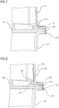
- FIG. 7 is an enlarged sectional view of a slit part of the intermediate plate. As shown in FIG. 7 , the outer peripheral side of the outer peripheral wall 19 of the intermediate plate 16 is covered by an outer edge portion at a lower part of the upper casing 14.
- a space enclosed by the upper casing 14 and the intermediate plate 16 is sealed by the outer edge portion at the lower part of the upper casing 14 and the outer peripheral wall 19, but the inside of the upper casing 14 and the outside of the upper casing 14 and the lower casing 15 communicate with each other via the slit 20.
- the outer size of an outer edge portion at an upper part of the lower casing 15 is approximately equal to the outer size of the outer edge portion at the lower part of the upper casing 14.
- the outer edge portion at the upper part of the lower casing 15 has a cutout 24. The cutout 24 further ensures communication between the inside and the outside of the upper casing 14 via the slit 20.
- FIG. 8 illustrates an action of drainage.
- Water having entered through the vent of the upper casing 14 drops to the intermediate plate 16 along the inner side of the upper casing 14 as shown by an arrow 25.
- the water dropped to the intermediate plate 16 is temporarily accumulated in a water-receiving portion 26 on a surface of the intermediate plate 16 between the outer peripheral wall 19 and the inner peripheral wall 21 of the intermediate plate 16.
- the water accumulated in the water-receiving portion 26 is drained through the slit 20 and the cutout 24 to the outside of the upper casing 14 and the lower casing 15, as shown by an arrow 27.
- the air circuit breaker configured as described above enables water having entered from the vent to be drained to the outside without letting the water enter the current-interruption portion.
- the outer peripheral side of the outer peripheral wall of the intermediate plate where the slit is provided is covered by the outer edge portion of the upper casing, entry of water into the slit from the outside can be prevented.
- the outer size of the outer edge portion at the upper part of the lower casing is approximately equal to the outer size of the outer edge portion at the lower part of the upper casing, and the outer edge portion at the upper part of the lower casing has the cutout. If the outer size of the outer edge portion at the upper part of the lower casing is set to be smaller than the outer size of the outer edge portion at the lower part of the upper casing, water accumulated in the water-receiving portion is drained through the slit to the outside without the cutout.
- FIG. 9 is an enlarged sectional view of an air circuit breaker according to embodiment 2.
- the configuration of the air circuit breaker in the present embodiment is the same as the configuration of the air circuit breaker in embodiment 1.
- the structure of the intermediate plate is different from that in embodiment 1.
- the intermediate plate 16 in the present embodiment is formed with the surface of the water-receiving portion 26 sloped.
- the water-receiving portion 26 descends toward the outer peripheral wall 19 side.
- the air circuit breaker configured as described above, water temporarily accumulated in the water-receiving portion 26 moves to the slit side along the slope, whereby the water can be efficiently drained.
- the air circuit breaker has improved reliability even in a case where a large amount of water enters.
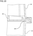
- FIG. 10 is an enlarged sectional view of an air circuit breaker according to embodiment 3.
- the configuration of the air circuit breaker in the present embodiment is the same as the configuration of the air circuit breaker in embodiment 1.
- the structure of the lower casing is different from that in embodiment 1.
- the lower casing 15 in the present embodiment has a protrusion 28 protruding toward the intermediate plate 16 side, on the inner side of the outer edge portion at the upper part. A distal end of the protrusion 28 contacts with a surface of the intermediate plate 16.
Landscapes
- Engineering & Computer Science (AREA)
- Power Engineering (AREA)
- Breakers (AREA)
Abstract
Description
- The present disclosure relates to an air circuit breaker.
- An air circuit breaker includes a current-interruption portion having a fixed element and a movable element for interrupting current, and an arc-extinguishing portion which extinguishes an arc generated between the fixed element and the movable element. The air circuit breaker is placed outdoors and therefore has a casing for preventing rain water, dust, or the like from entering the inside of a device. The casing is composed of an upper casing storing the arc-extinguishing portion, a lower casing storing the current-interruption portion, and an intermediate plate provided between the upper casing and the lower casing. In the air circuit breaker, hot gas is generated at the arc-extinguishing portion by heat of an arc generated between the movable element and the fixed element at the time of current interruption. The intermediate plate is provided for protecting the interruption portion from the hot gas. In addition, the upper casing has a vent for preventing increase in the internal pressure due to the hot gas. For preventing entry of a foreign material such as water or dust through the vent, the vent has a structure such as a labyrinth structure or a flapper structure.
- However, even if the vent has a structure such as a labyrinth structure or a flapper structure, it is impossible to perfectly prevent entry of a foreign material such as water or dust through the vent. Accordingly, such a structure that a drainage hole is provided to an outer wall of a casing and water having entered through a vent is drained through the drainage hole to the outside, is disclosed (see, for example, Patent Document 1). In addition, such a structure that an inside wall is provided inside a vent and water having entered through the vent is drained downward inside a casing through a bottom surface between an outer wall of the casing and the inside wall, is disclosed (see, for example, Patent Document 2).
-
- Patent Document 1:
Japanese Laid-Open Patent Publication No. 2004-129403 - Patent Document 2:
Japanese Laid-Open Utility Model Publication No. 4-111223 - However, in the structure in which the drainage hole is provided to the outer wall of the casing, the drainage hole is exposed to the outside, thus having a problem that a foreign material enters through the drainage hole. Meanwhile, in the structure in which water is drained downward inside the casing, water having entered cannot be drained to the outside, thus having a problem that water enters the current-interruption portion stored inside the lower casing.
- The present disclosure has been made to solve the above problems, and an object of the present disclosure is to provide an air circuit breaker having a drainage structure that enables water having entered through a vent to be drained to the outside without letting the water enter a current-interruption portion, and can prevent entry of water from the outside.
- An air circuit breaker according to the present disclosure includes: a current-interruption portion including a fixed element and a movable element; an arc-extinguishing portion which extinguishes an arc generated between the fixed element and the movable element; an upper casing having a vent and storing the arc-extinguishing portion; a lower casing storing the current-interruption portion; and an intermediate plate provided between the upper casing and the lower casing. The intermediate plate has an outer peripheral wall protruding toward the upper casing side, and an inner peripheral wall provided on an inner side of the outer peripheral wall so as to be opposed thereto. The outer peripheral wall has a slit at least at one location thereof. An outer peripheral side of the outer peripheral wall is covered by an outer edge portion of the upper casing. Inside of the upper casing and outside of the upper casing and the lower casing communicate with each other via the slit.
- In the air circuit breaker according to the present disclosure, the intermediate plate has the outer peripheral wall protruding toward the upper casing side and the inner peripheral wall provided on the inner side of the outer peripheral wall so as to be opposed thereto, the outer peripheral wall has the slit at least at one location thereof, the outer peripheral side of the outer peripheral wall is covered by the outer edge portion of the upper casing, and inside of the upper casing and outside of the upper casing and the lower casing communicate with each other via the slit. Thus, it becomes possible to drain water having entered through the vent, to the outside, without letting the water enter the current-interruption portion, and prevent entry of water from the outside.
-
- [
FIG. 1] FIG. 1 is a schematic view showing a major part of an air circuit breaker according toembodiment 1. - [
FIG. 2] FIG. 2 is a schematic sectional view showing the configuration of the air circuit breaker according toembodiment 1. - [
FIG. 3] FIG. 3 is a perspective view showing an intermediate plate according toembodiment 1. - [
FIG. 4] FIG. 4 is an enlarged top view of the intermediate plate according toembodiment 1. - [
FIG. 5] FIG. 5 is an enlarged perspective view of the intermediate plate according toembodiment 1. - [
FIG. 6] FIG. 6 is a sectional view of the air circuit breaker according toembodiment 1. - [
FIG. 7] FIG. 7 is an enlarged sectional view of the air circuit breaker according toembodiment 1. - [
FIG. 8] FIG. 8 illustrates drainage in the air circuit breaker according toembodiment 1. - [
FIG. 9] FIG. 9 is an enlarged sectional view of an air circuit breaker according toembodiment 2. - [
FIG. 10] FIG. 10 is an enlarged sectional view of an air circuit breaker according toembodiment 3. - Hereinafter, an air circuit breaker according to embodiments for carrying out the present disclosure will be described in detail with reference to the drawings. In the drawings, the same reference characters denote the same or corresponding parts.
-
FIG. 1 is a schematic view showing a major part of an air circuit breaker according toembodiment 1.FIG. 1 shows a state in which contacts of anair circuit breaker 100 are closed. Theair circuit breaker 100 includes afixed element 3 composed of afixed contact 1 and a fixed-contact metal base 2, and amovable element 6 composed of amovable contact 4 and a movable-contact metal base 5. Anupper conductor 8 is electrically connected to thefixed element 3, and alower conductor 9 is electrically connected to themovable element 6. In a closed state, themovable element 6 is moved to thefixed element 3 side by anactuator 7 so that themovable contact 4 is in contact with the fixedcontact 1. Current is flowing through theupper conductor 8, thefixed element 3, themovable element 6, and thelower conductor 9. - A
current detector 10 is provided to thelower conductor 9. When fault current exceeding the rated current flows in theair circuit breaker 100, thecurrent detector 10 detects the fault current. When the fault current is detected by the current detector, alatch 11 holding themovable element 6 is released, so that themovable element 6 is separated from thefixed element 3. Thus, opening operation is executed in theair circuit breaker 100. Thefixed element 3, themovable element 6, theactuator 7, theupper conductor 8, thelower conductor 9, thecurrent detector 10, and thelatch 11 compose a current-interruption portion 13. - When opening operation is performed in the
air circuit breaker 100, an arc is generated between thefixed contact 1 and themovable contact 4. The arc is elongated toward an arc-extinguishingportion 12. The arc-extinguishingportion 12 includes a plurality of arc-extinguishing plates 12a, and the arc elongated to the inside of the arc-extinguishingportion 12 is divided by the plurality of arc-extinguishing plates 12a, so that the arc voltage increases. In theair circuit breaker 100, when the arc voltage increases to power supply voltage of the circuit or higher, the current is interrupted. -
FIG. 2 is a schematic sectional showing the configuration of the air circuit breaker according to the present embodiment. InFIG. 2 , the detailed configurations of the arc-extinguishingportion 12 and the current-interruption portion 13, which are a major part of theair circuit breaker 100, are not shown. In theair circuit breaker 100, for preventing entry of a foreign material such as rain or dust, the arc-extinguishingportion 12 and the current-interruption portion 13 are stored inside a casing. Theair circuit breaker 100 of the present embodiment includes anupper casing 14 storing the arc-extinguishingportion 12, alower casing 15 storing the current-interruption portion 13, and anintermediate plate 16 provided between theupper casing 14 and thelower casing 15. Theupper casing 14 is located vertically above thelower casing 15. Theupper casing 14, thelower casing 15, and theintermediate plate 16 are made of materials such as resin having an insulation property, for example. Since an arc generated between thefixed contact 1 and themovable contact 4 has a high temperature, metal, resin, and the like forming the arc-extinguishingportion 12 are melted and vaporized to generate hot gas. Due to generation of hot gas, the gas pressure in theupper casing 14 increases. For preventing damage to theupper casing 14 or the like due to increase in the gas pressure, avent 17 is provided at a side surface of theupper casing 14. For preventing entry of rain, dust, or the like from the outside, aflapper 18 is provided on the outer side of thevent 17. Theflapper 18 is formed by a flexible insulation sheet, for example. Theflapper 18 normally closes thevent 17 and serves as a pressure relief device that opens thevent 17 only when the gas pressure inside theupper casing 14 increases. Theintermediate plate 16 is provided for protecting the current-interruption portion 13 from hot gas. - However, the
flapper 18 cannot perfectly prevent entry of a foreign material from the outside. For example, entry of water through a gap at a connection part of theflapper 18 or entry of rain, mist, or the like by wind blowing up from a lower side, cannot be perfectly prevented. The air circuit breaker of the present embodiment enables water having entered through the vent to be drained to the outside without letting the water enter the current-interruption portion. -
FIG. 3 is a perspective view of the intermediate plate of the air circuit breaker according to the present embodiment. Theintermediate plate 16 of the present embodiment has a rectangular shape of which the short-side length is about 40 cm and the long-side length is about 70 cm. Theintermediate plate 16 has an outerperipheral wall 19 protruding from the outer peripheral edge toward the upper casing side, and an innerperipheral wall 21 provided on the inner side of the outerperipheral wall 19 so as to be opposed to the outerperipheral wall 19. The wall thicknesses of the outerperipheral wall 19 and the innerperipheral wall 21 are about 6 mm, the wall height of the outerperipheral wall 19 is about 5 mm, and the wall height of the innerperipheral wall 21 is about 15 mm. The outerperipheral wall 19 hasslits 20 provided at two locations on each side.FIG. 4 is an enlarged top view of the intermediate plate at a part where the slit is provided.FIG. 5 is an enlarged perspective view of the intermediate plate at the part where the slit is provided. As shown inFIG. 4 andFIG. 5 , the outerperipheral wall 19 has theslit 20 formed by cutting a part of the outerperipheral wall 19. Theslit 20 is formed such that an upper part of the outerperipheral wall 19 and a side wall on the outer peripheral side are cut. In the air circuit breaker of the present embodiment, atransverse width 22 of theslit 20 is about 8 mm and adepth 23 on the outer peripheral side of theslit 20 is about 3 mm. The sizes of the outerperipheral wall 19 and the innerperipheral wall 21, and the number and the sizes of theslits 20 can be arbitrarily set in accordance with the size of the casing, an assumed amount of entering water, and the like. -
FIG. 6 is a sectional view of the air circuit breaker according to the present embodiment. InFIG. 6 , the arc-extinguishing portion and the current-interruption portion, which are a major part of theair circuit breaker 100, are not shown. Also, the flapper is not shown.FIG. 7 is an enlarged sectional view of a slit part of the intermediate plate. As shown inFIG. 7 , the outer peripheral side of the outerperipheral wall 19 of theintermediate plate 16 is covered by an outer edge portion at a lower part of theupper casing 14. Thus, a space enclosed by theupper casing 14 and theintermediate plate 16 is sealed by the outer edge portion at the lower part of theupper casing 14 and the outerperipheral wall 19, but the inside of theupper casing 14 and the outside of theupper casing 14 and thelower casing 15 communicate with each other via theslit 20. The outer size of an outer edge portion at an upper part of thelower casing 15 is approximately equal to the outer size of the outer edge portion at the lower part of theupper casing 14. The outer edge portion at the upper part of thelower casing 15 has acutout 24. Thecutout 24 further ensures communication between the inside and the outside of theupper casing 14 via theslit 20. - Next, drainage in the air circuit breaker of the present embodiment will be described.
FIG. 8 illustrates an action of drainage. Water having entered through the vent of theupper casing 14 drops to theintermediate plate 16 along the inner side of theupper casing 14 as shown by anarrow 25. The water dropped to theintermediate plate 16 is temporarily accumulated in a water-receivingportion 26 on a surface of theintermediate plate 16 between the outerperipheral wall 19 and the innerperipheral wall 21 of theintermediate plate 16. The water accumulated in the water-receivingportion 26 is drained through theslit 20 and thecutout 24 to the outside of theupper casing 14 and thelower casing 15, as shown by anarrow 27. - The air circuit breaker configured as described above enables water having entered from the vent to be drained to the outside without letting the water enter the current-interruption portion. In addition, since the outer peripheral side of the outer peripheral wall of the intermediate plate where the slit is provided is covered by the outer edge portion of the upper casing, entry of water into the slit from the outside can be prevented.
- In the air circuit breaker of the present embodiment, the outer size of the outer edge portion at the upper part of the lower casing is approximately equal to the outer size of the outer edge portion at the lower part of the upper casing, and the outer edge portion at the upper part of the lower casing has the cutout. If the outer size of the outer edge portion at the upper part of the lower casing is set to be smaller than the outer size of the outer edge portion at the lower part of the upper casing, water accumulated in the water-receiving portion is drained through the slit to the outside without the cutout.
-
FIG. 9 is an enlarged sectional view of an air circuit breaker according toembodiment 2. The configuration of the air circuit breaker in the present embodiment is the same as the configuration of the air circuit breaker inembodiment 1. In the present embodiment, the structure of the intermediate plate is different from that inembodiment 1. - As shown in
FIG. 9 , theintermediate plate 16 in the present embodiment is formed with the surface of the water-receivingportion 26 sloped. The water-receivingportion 26 descends toward the outerperipheral wall 19 side. - In the air circuit breaker configured as described above, water temporarily accumulated in the water-receiving
portion 26 moves to the slit side along the slope, whereby the water can be efficiently drained. Thus, the air circuit breaker has improved reliability even in a case where a large amount of water enters. -
FIG. 10 is an enlarged sectional view of an air circuit breaker according toembodiment 3. The configuration of the air circuit breaker in the present embodiment is the same as the configuration of the air circuit breaker inembodiment 1. In the present embodiment, the structure of the lower casing is different from that inembodiment 1. - As shown in
FIG. 10 , thelower casing 15 in the present embodiment has aprotrusion 28 protruding toward theintermediate plate 16 side, on the inner side of the outer edge portion at the upper part. A distal end of theprotrusion 28 contacts with a surface of theintermediate plate 16. - In the air circuit breaker configured as described above, even if water drained through the slit to the outside enters the inside of the
lower casing 15 through a gap between connection surfaces of theintermediate plate 16 and thelower casing 15, the entry of water can be prevented by theprotrusion 28. Thus, entry of water into the current-interruption portion stored inside the lower casing can be prevented, whereby reliability of the air circuit breaker is improved. - Although the disclosure is described above in terms of various exemplary embodiments and implementations, it should be understood that the various features, aspects, and functionality described in one or more of the individual embodiments are not limited in their applicability to the particular embodiment with which they are described, but instead can be applied, alone or in various combinations to one or more of the embodiments of the disclosure.
- It is therefore understood that numerous modifications which have not been exemplified can be devised without departing from the scope of the present disclosure. For example, at least one of the constituent components may be modified, added, or eliminated. At least one of the constituent components mentioned in at least one of the preferred embodiments may be selected and combined with the constituent components mentioned in another preferred embodiment.
-
- 1
- fixed contact
- 2
- fixed-contact metal base
- 3
- fixed element
- 4
- movable contact
- 5
- movable-contact metal base
- 6
- movable element
- 7
- actuator
- 8
- upper conductor
- 9
- lower conductor
- 10
- current detector
- 11
- latch
- 12
- arc-extinguishing portion
- 12a
- arc-extinguishing plate
- 13
- current-interruption portion
- 14
- upper casing
- 15
- lower casing
- 16
- intermediate plate
- 17
- vent
- 18
- flapper
- 19
- outer peripheral wall
- 20
- slit
- 21
- inner peripheral wall
- 24
- cutout
- 26
- water-receiving portion
- 28
- protrusion
Claims (3)
- An air circuit breaker comprising:a current-interruption portion including a fixed element and a movable element;an arc-extinguishing portion which extinguishes an arc generated between the fixed element and the movable element;an upper casing having a vent and storing the arc-extinguishing portion;a lower casing storing the current-interruption portion; andan intermediate plate provided between the upper casing and the lower casing, whereinthe intermediate plate has an outer peripheral wall protruding toward the upper casing side, and an inner peripheral wall provided on an inner side of the outer peripheral wall so as to be opposed thereto,the outer peripheral wall has a slit at least at one location thereof,an outer peripheral side of the outer peripheral wall is covered by an outer edge portion of the upper casing, andinside of the upper casing and outside of the upper casing and the lower casing communicate with each other via the slit.
- The air circuit breaker according to claim 1,
wherein
a surface of the intermediate plate between the outer peripheral wall and the inner peripheral wall descends toward the outer peripheral wall side. - The air circuit breaker according to claim 1 or 2, whereinthe lower casing has, on an inner side of an outer edge portion thereof, a protrusion protruding toward the intermediate plate side, anda distal end of the protrusion contacts with a surface of the intermediate plate.
Applications Claiming Priority (1)
| Application Number | Priority Date | Filing Date | Title |
|---|---|---|---|
| PCT/JP2021/035528 WO2023053169A1 (en) | 2021-09-28 | 2021-09-28 | Air circuit breaker |
Publications (2)
| Publication Number | Publication Date |
|---|---|
| EP4411771A1 true EP4411771A1 (en) | 2024-08-07 |
| EP4411771A4 EP4411771A4 (en) | 2024-11-20 |
Family
ID=85781463
Family Applications (1)
| Application Number | Title | Priority Date | Filing Date |
|---|---|---|---|
| EP21959222.7A Pending EP4411771A4 (en) | 2021-09-28 | 2021-09-28 | Air circuit breaker |
Country Status (3)
| Country | Link |
|---|---|
| EP (1) | EP4411771A4 (en) |
| JP (1) | JP7462850B2 (en) |
| WO (1) | WO2023053169A1 (en) |
Families Citing this family (1)
| Publication number | Priority date | Publication date | Assignee | Title |
|---|---|---|---|---|
| WO2025104835A1 (en) * | 2023-11-15 | 2025-05-22 | 三菱電機株式会社 | Air circuit breaker |
Family Cites Families (7)
| Publication number | Priority date | Publication date | Assignee | Title |
|---|---|---|---|---|
| JP2545482Y2 (en) | 1991-03-11 | 1997-08-25 | 古河電気工業株式会社 | Electrical junction box |
| JP4059390B2 (en) | 2002-10-03 | 2008-03-12 | 東京電力株式会社 | Road-mounted transformer device |
| CN201327781Y (en) * | 2007-03-30 | 2009-10-14 | 赛雪龙公司 | Circuit breaker |
| CN201369302Y (en) * | 2009-02-06 | 2009-12-23 | 湘潭电机股份有限公司 | Direct-current electromagnetic high-speed breaker |
| WO2011128379A1 (en) * | 2010-04-16 | 2011-10-20 | Abb Technology Ag | Arc chute for a circuit breaker, circuit breaker and method for assembling an arc chute |
| WO2017183679A1 (en) * | 2016-04-22 | 2017-10-26 | 三菱電機株式会社 | Contactor device for circuit breaker and circuit breaker using same contactor device |
| CN207977285U (en) * | 2017-12-26 | 2018-10-16 | 浙江正泰电器股份有限公司 | external operation handle |
-
2021
- 2021-09-28 EP EP21959222.7A patent/EP4411771A4/en active Pending
- 2021-09-28 WO PCT/JP2021/035528 patent/WO2023053169A1/en not_active Ceased
- 2021-09-28 JP JP2023550759A patent/JP7462850B2/en active Active
Also Published As
| Publication number | Publication date |
|---|---|
| JP7462850B2 (en) | 2024-04-05 |
| WO2023053169A1 (en) | 2023-04-06 |
| JPWO2023053169A1 (en) | 2023-04-06 |
| EP4411771A4 (en) | 2024-11-20 |
Similar Documents
| Publication | Publication Date | Title |
|---|---|---|
| KR101051517B1 (en) | Circuit breaker | |
| KR100964260B1 (en) | Circuit breaker | |
| EP2393095A2 (en) | Mold cased circuit brreaker | |
| KR20060035194A (en) | Arc extinguishing device for circuit breaker | |
| EP4411771A1 (en) | Air circuit breaker | |
| KR101860348B1 (en) | Vacuum interrupter for vacuum circuit breaker | |
| KR200393296Y1 (en) | Arc chamber for circuit breaker | |
| JPH04212227A (en) | Arc chute structure of current-limit type breaker | |
| KR20180027098A (en) | Arc extinguishing structures | |
| HK40111160A (en) | Air circuit breaker | |
| CN1071049C (en) | Arc gas exhauster for circuit breaker | |
| CN112309783B (en) | Door phase separation device in molded case circuit breaker | |
| KR0152872B1 (en) | Arc chamber for electric switchgear | |
| JPH07130272A (en) | Terminal cover and circuit breaker equipped with terminal cover | |
| KR200482131Y1 (en) | Upper cover for mold cased circuit breaker | |
| KR100860782B1 (en) | Earth leakage breaker | |
| KR102788607B1 (en) | Air circuit breaker having insulation paper to prevent terminal short circuit | |
| JP7700647B2 (en) | Circuit Breakers | |
| CN113745073B (en) | Plastic case circuit breaker with zero arcing device | |
| JP3216780B2 (en) | Circuit breaker | |
| US20130112657A1 (en) | Arc chamber assembly for use in moulded case circuit breakers | |
| JP6245673B1 (en) | Power line connection device | |
| CN219591331U (en) | Circuit breaker | |
| JP4696665B2 (en) | Earth leakage breaker | |
| KR20130102359A (en) | A case of molded-case circuit breaker for improving the withstanding voltage |
Legal Events
| Date | Code | Title | Description |
|---|---|---|---|
| STAA | Information on the status of an ep patent application or granted ep patent |
Free format text: STATUS: THE INTERNATIONAL PUBLICATION HAS BEEN MADE |
|
| PUAI | Public reference made under article 153(3) epc to a published international application that has entered the european phase |
Free format text: ORIGINAL CODE: 0009012 |
|
| STAA | Information on the status of an ep patent application or granted ep patent |
Free format text: STATUS: REQUEST FOR EXAMINATION WAS MADE |
|
| 17P | Request for examination filed |
Effective date: 20231031 |
|
| AK | Designated contracting states |
Kind code of ref document: A1 Designated state(s): AL AT BE BG CH CY CZ DE DK EE ES FI FR GB GR HR HU IE IS IT LI LT LU LV MC MK MT NL NO PL PT RO RS SE SI SK SM TR |
|
| A4 | Supplementary search report drawn up and despatched |
Effective date: 20241018 |
|
| RIC1 | Information provided on ipc code assigned before grant |
Ipc: H01H 33/59 20060101ALI20241014BHEP Ipc: H01H 73/06 20060101ALI20241014BHEP Ipc: H01H 33/08 20060101ALI20241014BHEP Ipc: H01H 9/04 20060101ALI20241014BHEP Ipc: H01H 33/53 20060101AFI20241014BHEP |
|
| REG | Reference to a national code |
Ref country code: HK Ref legal event code: DE Ref document number: 40111160 Country of ref document: HK |
|
| DAV | Request for validation of the european patent (deleted) | ||
| DAX | Request for extension of the european patent (deleted) | ||
| GRAP | Despatch of communication of intention to grant a patent |
Free format text: ORIGINAL CODE: EPIDOSNIGR1 |
|
| STAA | Information on the status of an ep patent application or granted ep patent |
Free format text: STATUS: GRANT OF PATENT IS INTENDED |
|
| GRAJ | Information related to disapproval of communication of intention to grant by the applicant or resumption of examination proceedings by the epo deleted |
Free format text: ORIGINAL CODE: EPIDOSDIGR1 |
|
| INTG | Intention to grant announced |
Effective date: 20251218 |
|
| STAA | Information on the status of an ep patent application or granted ep patent |
Free format text: STATUS: REQUEST FOR EXAMINATION WAS MADE |
|
| INTC | Intention to grant announced (deleted) | ||
| REG | Reference to a national code |
Ref country code: DE Ref legal event code: R079 Free format text: PREVIOUS MAIN CLASS: H01H0033530000 Ipc: H01H0009340000 |
|
| GRAP | Despatch of communication of intention to grant a patent |
Free format text: ORIGINAL CODE: EPIDOSNIGR1 |
|
| STAA | Information on the status of an ep patent application or granted ep patent |
Free format text: STATUS: GRANT OF PATENT IS INTENDED |
|
| RIC1 | Information provided on ipc code assigned before grant |
Ipc: H01H 9/34 20060101AFI20260325BHEP Ipc: H01H 33/53 20060101ALI20260325BHEP Ipc: H01H 9/04 20060101ALI20260325BHEP Ipc: H01H 33/08 20060101ALI20260325BHEP Ipc: H01H 73/06 20060101ALI20260325BHEP Ipc: H01H 33/59 20060101ALI20260325BHEP |