EP4411688A1 - Management system - Google Patents
Management system Download PDFInfo
- Publication number
- EP4411688A1 EP4411688A1 EP22892505.3A EP22892505A EP4411688A1 EP 4411688 A1 EP4411688 A1 EP 4411688A1 EP 22892505 A EP22892505 A EP 22892505A EP 4411688 A1 EP4411688 A1 EP 4411688A1
- Authority
- EP
- European Patent Office
- Prior art keywords
- work
- work machine
- map image
- display device
- control unit
- Prior art date
- Legal status (The legal status is an assumption and is not a legal conclusion. Google has not performed a legal analysis and makes no representation as to the accuracy of the status listed.)
- Pending
Links
- 230000033001 locomotion Effects 0.000 claims description 34
- 230000000694 effects Effects 0.000 claims description 15
- 239000002689 soil Substances 0.000 description 23
- 238000004891 communication Methods 0.000 description 20
- 238000009412 basement excavation Methods 0.000 description 9
- 230000001133 acceleration Effects 0.000 description 3
- 230000008878 coupling Effects 0.000 description 2
- 238000010168 coupling process Methods 0.000 description 2
- 238000005859 coupling reaction Methods 0.000 description 2
- 238000010586 diagram Methods 0.000 description 2
- 238000000034 method Methods 0.000 description 2
- 239000003086 colorant Substances 0.000 description 1
- 230000008602 contraction Effects 0.000 description 1
- 238000001514 detection method Methods 0.000 description 1
- 230000006866 deterioration Effects 0.000 description 1
- 239000002440 industrial waste Substances 0.000 description 1
- 230000002452 interceptive effect Effects 0.000 description 1
- 239000002699 waste material Substances 0.000 description 1
Images


Classifications
-
- E—FIXED CONSTRUCTIONS
- E02—HYDRAULIC ENGINEERING; FOUNDATIONS; SOIL SHIFTING
- E02F—DREDGING; SOIL-SHIFTING
- E02F9/00—Component parts of dredgers or soil-shifting machines, not restricted to one of the kinds covered by groups E02F3/00 - E02F7/00
- E02F9/20—Drives; Control devices
- E02F9/2025—Particular purposes of control systems not otherwise provided for
- E02F9/2054—Fleet management
-
- E—FIXED CONSTRUCTIONS
- E02—HYDRAULIC ENGINEERING; FOUNDATIONS; SOIL SHIFTING
- E02F—DREDGING; SOIL-SHIFTING
- E02F3/00—Dredgers; Soil-shifting machines
- E02F3/04—Dredgers; Soil-shifting machines mechanically-driven
- E02F3/28—Dredgers; Soil-shifting machines mechanically-driven with digging tools mounted on a dipper- or bucket-arm, i.e. there is either one arm or a pair of arms, e.g. dippers, buckets
- E02F3/36—Component parts
- E02F3/42—Drives for dippers, buckets, dipper-arms or bucket-arms
- E02F3/43—Control of dipper or bucket position; Control of sequence of drive operations
- E02F3/435—Control of dipper or bucket position; Control of sequence of drive operations for dipper-arms, backhoes or the like
- E02F3/439—Automatic repositioning of the implement, e.g. automatic dumping, auto-return
-
- E—FIXED CONSTRUCTIONS
- E02—HYDRAULIC ENGINEERING; FOUNDATIONS; SOIL SHIFTING
- E02F—DREDGING; SOIL-SHIFTING
- E02F9/00—Component parts of dredgers or soil-shifting machines, not restricted to one of the kinds covered by groups E02F3/00 - E02F7/00
- E02F9/20—Drives; Control devices
- E02F9/2025—Particular purposes of control systems not otherwise provided for
- E02F9/205—Remotely operated machines, e.g. unmanned vehicles
-
- E—FIXED CONSTRUCTIONS
- E02—HYDRAULIC ENGINEERING; FOUNDATIONS; SOIL SHIFTING
- E02F—DREDGING; SOIL-SHIFTING
- E02F9/00—Component parts of dredgers or soil-shifting machines, not restricted to one of the kinds covered by groups E02F3/00 - E02F7/00
- E02F9/26—Indicating devices
- E02F9/261—Surveying the work-site to be treated
- E02F9/262—Surveying the work-site to be treated with follow-up actions to control the work tool, e.g. controller
Definitions
- the present invention relates to a management system that manages a plurality of work machines.
- Patent Literature 1 discloses a management system of industrial vehicles that displays a map image on a display device.
- the map image symbols indicating the positions of a plurality of industrial vehicles are superimposed and displayed.
- a display aspect of the symbol is set to be different according to operating time of the industrial vehicle.
- Patent Literature 1 Japanese Patent Application Laid-Open No. 2013-235485
- Patent Literature 1 can recognize a position and operating time of each work machine (industrial vehicle) from information displayed on a display device, but for example, when an operator in a cockpit remotely operates one work machine while viewing the display device, if another work machine around the one work machine is being automatically driven, the other work machine may make an unexpected movement for the operator, and therefore there is a problem of deterioration in workability and safety.
- An object of the present invention is to provide a management system that makes it possible to improve workability and safety when a plurality of work machines perform work.
- the present invention provides a management system including a display device that displays a map image, a reception device, and a display control unit.
- the reception device receives, from each of a plurality of work machines, position information of the work machine and information on whether or not the work machine is being automatically driven.
- the display control unit superimposes, on the map image, and displays, on the display device, an image indicating that the work machine is being automatically driven in association with a position of the work machine being automatically driven.
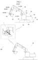
- FIG. 1 is a view illustrating a management system 100 according to one embodiment of the present invention.
- the management system 100 manages a plurality of work machines 20.
- the management system 100 includes the plurality of work machines 20 and a management room 1.
- the management room 1 is a cockpit, for example.
- An operator in the management room 1 remotely teaches motion to each of the several work machines 20.
- the teaching is also called direct teaching, is a teaching method in which an operator operates an operation device to teach motion, and is also called a direct instruction method. Then, the operator can remotely control the other work machine 20 while the work machine 20 having been taught is performing automatic drive in accordance with the content.
- FIG. 2 is a view illustrating the display group 2 of the management system 100.
- the management room 1 includes the display group 2.
- the display group 2 includes a plurality of displays, and these displays include a display device 3, a remote control display device 4, and a map display device 5.
- the management room 1 includes a speaker 6 (see FIG. 3 ).
- the work machine 20 is a hydraulic excavator, and includes a machine body 25 including a lower travelling body 21 and an upper slewing body 22, an attachment 30, and a work drive device 40.
- the lower travelling body 21 includes a pair of crawlers, and can travel on the ground by the pair of crawlers moving.
- the upper slewing body 22 is slewably attached to the lower travelling body 21 via a slewing device 24.
- the slewing device 24 is a slewing drive device that slews the upper slewing body 22.
- the upper slewing body 22 includes a cab (operator's room) 23 positioned at a front part thereof.
- the attachment 30 is a work device and is attached to the upper slewing body 22 so as to be able to perform work motion including vertical rotation.
- the attachment 30 includes a boom 31, an arm 32, and a bucket 33.
- the boom 31 has a base end part attached to the upper slewing body 22 so as to be vertically rotatable (capable of being raised and lowered) and a tip end part on the opposite side.
- the arm 32 has a base end part attached to the tip end part of the boom 31 so as to be vertically rotatable with respect to the boom 31, and a tip end part on the opposite side.
- the bucket 33 is attached to the tip end part of the arm 32 so as to be rotatable in the front-rear direction with respect to the arm 32.
- the bucket 33 is a tip end attachment that is a tip end part of the attachment 30, and is a part that performs work such as excavation, leveling, and scooping of soil.
- the work target object held by the bucket 33 is not limited to soil, may be stones, and may be waste (industrial waste or the like).
- the tip end attachment is not limited to the bucket 33, and may be a grapple, a lifting magnet, or the like.
- the work drive device 40 hydraulically moves the attachment 30 to causes the work motion to be performed.
- the work drive device 40 includes a plurality of hydraulic cylinders each of which is extendable and contractable, and the plurality of cylinders include a boom cylinder 41, an arm cylinder 42, and a bucket cylinder 43.
- the boom cylinder 41 rotates the boom 31 with respect to the upper slewing body 22.
- the boom cylinder 41 has a base end part rotatably coupled to the upper slewing body 22 and a tip end part rotatably coupled to the boom 31.
- the arm cylinder 42 rotates the arm 32 with respect to the boom 31.
- the arm cylinder 42 has a base end part rotatably coupled to the boom 31 and a tip end part rotatably coupled to the arm 32.
- the bucket cylinder 43 rotates the bucket 33 with respect to the arm 32.
- the bucket cylinder 43 has a base end part rotatably coupled to the arm 32 and a tip end part rotatably coupled to the link member 34.
- the link member 34 is rotatably coupled to the bucket 33, and couples the bucket cylinder 43 and the bucket 33 to each other.
- the work machine 20 further includes a slewing angle sensor 52, which is a slewing angle detector, and a work posture detector 60.
- the slewing angle sensor 52 detects a slewing angle of the upper slewing body 22 with respect to the lower travelling body 21.
- the slewing angle sensor 52 is, for example, an encoder, a resolver, or a gyro sensor.
- the slewing angle of the upper slewing body 22 when the front of the upper slewing body 22 coincides with the front of the lower travelling body 21 is 0°.
- the work posture detector 60 detects a work posture of the attachment 30.
- the work posture detector 60 includes a boom inclination angle sensor 61, an arm inclination angle sensor 62, and a bucket inclination angle sensor 63.
- the boom inclination angle sensor 61 is attached to the boom 31 and detects a posture of the boom 31.
- the boom inclination angle sensor 61 acquires an inclination angle of the boom 31 with respect to a horizon.
- the boom inclination angle sensor 61 is an inclination (acceleration) sensor, for example.
- the work posture detector 60 may include, in place of the boom inclination angle sensor 61, a rotation angle sensor that detects a rotation angle of a boom foot pin (boom base end) or a stroke sensor that detects a stroke amount of the boom cylinder 41.
- the arm inclination angle sensor 62 is attached to the arm 32 and detects the posture of the arm 32.
- the arm inclination angle sensor 62 acquires an inclination angle of the arm 32 with respect to a horizon.
- the arm inclination angle sensor 62 is an inclination (acceleration) sensor, for example.
- the work posture detector 60 may include, in place of the arm inclination angle sensor 62, a rotation angle sensor that detects a rotation angle of an arm coupling pin (arm base end) or a stroke sensor that detects a stroke amount of the arm cylinder 42.
- the bucket inclination angle sensor 63 is attached to the link member 34 and detects the posture of the bucket 33.
- the bucket inclination angle sensor 63 acquires an inclination angle of the bucket 33 with respect to a horizon.
- the bucket inclination angle sensor 63 is an inclination (acceleration) sensor, for example.
- the work posture detector 60 may include, in place of the bucket inclination angle sensor 63, a rotation angle sensor that detects a rotation angle of a bucket coupling pin (bucket base end) or a stroke sensor that detects a stroke amount of the bucket cylinder 43.
- the work machine 20 includes a camera 55.
- the camera 55 is attached to the boom 31.
- the camera 55 may be attached to the upper slewing body 22.
- the camera 55 captures an image of the front or the like of the upper slewing body 22 from the same viewpoint as the operator positioned in the cab 23.
- the work machine 20 includes a GNSS sensor 56.
- a global navigation satellite system (GNSS) sensor 56 is provided in the upper slewing body 22, and detects the coordinate of the upper slewing body 22 in a work site.
- the GNSS sensor 56 is a positioning sensor such as a GPS sensor, and acquires the position of the work machine 20 (upper slewing body 22) in a global coordinate system.
- the work machine 20 may include a ranging sensor such as a total station in place of the GNSS sensor 56.
- FIG. 3 is a block diagram of the management system 100.
- the work machine 20 includes a work machine side control unit 11, a work machine side communication device 12, and a storage device 13.
- Information regarding the slewing angle (posture) of the upper slewing body 22 with respect to the lower travelling body 21 detected by the slewing angle sensor 52 is input to the work machine side control unit 11.
- Information regarding the posture of the boom 31 detected by the boom inclination angle sensor 61 is input to the work machine side control unit 11.
- Information regarding the posture of the arm 32 detected by the arm inclination angle sensor 62 is input to the work machine side control unit 11.
- Information regarding the posture of the bucket 33 detected by the bucket inclination angle sensor 63 is input to the work machine side control unit 11.
- Image data captured by the camera 55 is input to the work machine side control unit 11.
- Position information acquired by the GNSS sensor 56 is input to the work machine side control unit 11.
- the work machine side control unit 11 automatically controls the work machine 20.
- the work machine side control unit 11 controls the movement of the upper slewing body 22 and the attachment 30 so that the upper slewing body 22 and the attachment 30 perform a series of motions.
- the work machine side control unit 11 automatically moves the slewing device 24 and the attachment 30 based on detection values of the slewing angle sensor 52 and the work posture detector 60.
- the series of motions is a motion of excavating soil and removing the soil.
- the work machine side control unit 11 controls the movement of the upper slewing body 22 and the attachment 30 in accordance with an instruction from the management room 1.
- the work machine side communication device 12 can communicate with a management room side communication device 9 described later of the management room 1.
- the storage device 13 stores work content remotely taught from the management room 1.
- the management room 1 includes a management room side control unit 7, an operation device 8, and the management room side communication device 9.
- the operation device 8 includes a device necessary for the operator to remotely operate the work machine 20 such as an operation lever and an operation button.
- the management room side communication device 9 can communicate with the work machine side communication device 12 of the work machine 20.
- the work machine 20 When the operator performs teaching from the management room 1, the work machine 20 is set to a teaching mode by a remote operation from the management room 1. When the work machine 20 is set to the teaching mode, the operator remotely controls the work machine 20 by operating the operation device 8. When the work machine 20 is remotely controlled, a landscape captured by the camera 55 is displayed on the display group 2. The operation content by the remote control is stored in the storage device 13. Thereafter, the work machine 20 is set to an automatic drive mode by a remote operation from the management room 1. When the work machine 20 is set to the automatic drive mode, the work machine 20 performs automatic drive along with the stored operation content.
- a series of motions performed by the work machine 20 is to repeat motions in order such as excavating (excavate) soil from a soil pit (not illustrated) with the bucket 33, slewing (lift slewing) the upper slewing body 22 toward a dump truck (not illustrated) while holding the soil, removing (soil removal) soil to a loading platform (not illustrated) of the dump truck, and slewing (return slewing) the upper slewing body 22 toward the soil pit.
- a series of motions by automatic drive has a plurality of motion phases (motion content).
- the plurality of motion phases include excavation, lift slewing, soil removal, and return slewing.
- the operator in the management room 1 remotely controls the other work machines 20 by operating the operation device 8.
- the management room side control unit 7 causes the remote control display device 4 to display an image captured by the camera 55 mounted on the work machine 20 to be remotely controlled.
- the operator in the management room 1 can suitably control the work machine 20 to be remotely controlled while viewing the remote control display device 4.
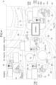
- FIG. 4 is a view illustrating a map image 70.
- the map display device 5 displays the map image 70.
- the management room side communication device (reception device) 9 receives position information of the work machine 20 and information on whether or not the work machine 20 is being automatically driven.
- the position information of the work machine 20 is acquired by the GNSS sensor 56.
- the automatic drive mode is an example of information indicating that the work machine 20 is being automatically driven.
- the management room side control unit 7 superimposes, on the map image 70, and displays, on the map display device 5, an icon 71 indicating the work machine 20 at the position of the work machine 20 on the map image 70. Due to this, the operator knows the position on the map image 70 of each of the plurality of work machines 20.
- the management room side control unit (display control unit) 7 superimposes, on the map image 70, and displays, on the map display device 5, an icon (image) 72 indicating that the work machine 20 is being automatically driven in association with the position of the work machine 20 being automatically driven on the map image 70.
- the icon 72 is displayed in the vicinity of the icon 71, but the present invention is not limited to this as long as the icon 72 is associated with the icon 71.
- the icon 72 may be displayed so as to overlap the icon 71, or the icon 71 and the icon 72 may be connected by a line.
- the operator in the management room 1 can grasp which work machine 20 is being automatically driven. Therefore, when remotely controlling another work machine 20, the operator can keep this work machine 20 from inadvertently approaching the work machine 20 being automatically driven. Therefore, workability and safety can be improved in the work site where the plurality of work machines 20 performs work.
- the management room side communication device 9 receives information regarding the motion phase from the work machine 20 being automatically driven.
- the motion phases of the series of motions are excavation, lift slewing, soil removal, and return slewing.
- the management room side control unit 7 displays, on the map display device 5, an icon 72 (display images) of a different aspect in accordance with the motion phase.
- an icon 72a representing soil removal is displayed on the map display device 5. Due to this, the operator knows that the work machine 20 being automatically driven is currently performing soil removal.
- an icon 72b representing excavation is displayed on the map display device 5. Then, with switching of the motion phase, the icon 72 to be displayed is also switched.
- the operator can recognize whether or not the motion phase is normally switched from the change (switching) in the aspect of the icon 72. As a result, the operator can grasp whether or not the work machine 20 being automatically driven is normally moving.
- the management room side control unit 7 superimposes, on the map image 70, and displays, on the map display device 5, an icon (image) 76 indicating that the work machine 20 is not being automatically driven in association with the position of the work machine 20 not being automatically driven on the map image 70.
- the icon 76 is displayed in the vicinity of the icon 71, but the present invention is not limited to this as long as the icon 76 is associated with the icon 71.
- the icon 76 may be displayed so as to overlap the icon 71, or the icon 71 and the icon 76 may be connected by a line.
- the operator in the management room 1 can grasp which work machine 20 is not being automatically driven. Therefore, when remotely controlling another work machine 20, the operator can keep this work machine 20 from inadvertently approaching the work machine 20 not being automatically driven.
- the management room side communication device 9 receives position information of the dump truck from each of a plurality of dump trucks.
- the position information of the dump truck is acquired by a GNSS sensor mounted on the dump truck.
- the dump truck may be automatically driven or manually driven.
- the management room side control unit 7 superimposes, on the map image 70, and displays, on the map display device 5, an icon 90 indicating the dump truck at the position of the dump truck on the map image 70. Due to this, the operator knows the position on the map image 70 of each of the plurality of dump trucks.
- the management room side communication device 9 receives information regarding a work history from each of the plurality of work machines 20.
- the work history is information indicating when, what work, and how many times (how many hours) was performed, and is created by the work machine side control unit 11. Examples of the work performed by the work machine 20 include slope finishing work, groove excavation work, and horizontal leveling work.
- the management room side control unit 7 superimposes, on the map image 70, and displays, on the map display device 5, an icon (image) 73 indicating the work history of the work machine 20 in association with the position of the work machine 20 on the map image 70.
- the icon 73 is displayed in the vicinity of the icon 71, but the present invention is not limited to this as long as the icon 73 is associated with the icon 71.
- the icon 73 may be displayed so as to overlap the icon 71, or the icon 71 and the icon 73 may be connected by a line.
- the operator in the management room 1 can grasp the work history of each of the work machines 20. Therefore, the operator can grasp how much work is being performed by which work machine 20.
- the management room side communication device 9 receives the position information of a worked region.
- the position information of the worked region is position information of a region where the work machine 20 has ended the work, and is created by the work machine side control unit 11, for example.
- the management room side control unit 7 superimposes, on the map image 70, and displays, on the map display device 5, an image indicating a worked region 77 on the map image 70.
- the image of the worked region 77 is displayed in a size corresponding to the size of the region 77.
- the operator in the management room 1 can grasp the worked region 77. Therefore, the operator can grasp in how much region the work has been performed. Then, when the worked region 77 is a region where the work machine 20 of automatic drive works, the operator can make a plan so as to perform finishing work on this region by the work machine 20 of manual driving.
- the management room side communication device 9 receives the position information of an unworked region.
- the position information of the unworked region is position information of a region where the work machine 20 performs work from now on, and is created by the work machine side control unit 11 based on a work plan, for example.
- the management room side control unit 7 superimposes, on the map image 70, and displays, on the map display device 5, an image indicating an unworked region 78 on the map image 70.
- the image of the unworked region 78 is displayed in a size corresponding to the size of the region 78.
- the operator in the management room 1 can grasp the unworked region 78. Therefore, the operator can grasp in how much region the work remains. Then, the operator can make a plan which work machine 20 to perform work on the unworked region 78. That is, when the work machine 20 in an idle state or in a state where the work is finished soon exists near the unworked region 78, the operator can make a plan so as to dispatch this work machine 20 to the unworked region 78 to perform the work.
- the management room side control unit 7 may automatically determine which work machine 20 to perform work on the unworked region 78 from the work situation of each of the plurality of work machines 20.
- the management room side control unit (machine passage acquisition unit) 7 acquires information on a machine passage from a machine passage management device that manages information on the machine passage, which is a passage of each of the plurality of work machines 20.
- the machine passage management device may be a storage device connected to the management room side control unit 7 of the management room 1, or may be a server or the like provided outside the management room 1 and communicating with the management room side communication device 9.
- the management room side control unit 7 superimposes, on the map image 70, and displays, on the map display device 5, an image indicating a machine passage 79 on the map image 70.
- the operator in the management room 1 can grasp the passage of the work machine 20. Therefore, the operator can make consideration so that a dump truck or the like does not enter the passage of the work machine 20.
- the management room side control unit (dump passage acquisition unit) 7 acquires information on a dump passage from a dump passage management device that manages information on the dump passage, which is a passage of a dump truck.
- the dump passage management device may be a storage device connected to the management room side control unit 7 of the management room 1, or may be a server or the like provided outside the management room 1 and communicating with the management room side communication device 9.
- the management room side control unit 7 superimposes, on the map image 70, and displays, on the map display device 5, an image indicating a dump passage 80 on the map image 70.
- the operator in the management room 1 can grasp the passage of the dump truck. Therefore, the operator can make consideration so that the work machine 20 or the like does not enter the passage of the dump truck.
- the management room side communication device 9 receives information regarding the movable range at a current position of the work machine 20 from each of the plurality of work machines 20.
- the movable range at the current position is a movable range that can be obtained by the slewing of the upper slewing body 22 and the extension and contraction of the attachment 30 without traveling of the work machine 20.
- the management room side control unit 7 superimposes, on the map image 70, and displays, on the map display device 5, an image indicating a movable range 81 at the current position of the work machine 20 in association with the position of the work machine 20 on the map image 70. At this time, the image of the movable range 81 is displayed in a size corresponding to the size of the movable range 81.
- the operator in the management room 1 can grasp the movable range 81 of each of the work machines 20. Therefore, the operator can make consideration so that a dump truck or the like does not enter the movable range 81 of the work machine 20.
- the operator can keep this work machine 20 from inadvertently approaching the movable range 81 of the other work machine 20.
- the management room side communication device 9 receives information regarding the work range from each of the plurality of work machines 20.
- the work range is acquired based on a movement range of the tip end of the bucket 33, for example.
- the position of the tip end of the bucket 33 is calculated from the length of the attachment 30 (boom 31, arm 32, and bucket 33) and the posture of the attachment 30.
- the management room side control unit 7 superimposes, on the map image 70, and displays, on the map display device 5, an image indicating a work range 74 of the work machine 20 in association with the position of the work machine 20 on the map image 70.
- the work range 74 is included in the movable range 81.
- the management room side control unit 7 displays, on the map display device 5, the image of the work range 74 in a size corresponding to the size of the work range 74.
- the operator in the management room 1 can grasp the work range 74 of each of the work machines 20. Therefore, the operator can grasp in how much range the work machine 20 has worked or in how much range it is working. When remotely controlling another work machine 20, the operator can keep this work machine 20 from inadvertently approaching the work range 74 of the other work machine 20.
- the work range 74 is displayed on the map display device 5 in a size corresponding to its size. Therefore, by viewing the map display device 5, the operator in the management room 1 can grasp the size of the work range 74 of each of the work machines 20.
- the management room side communication device 9 receives information regarding a progress situation of work in the work range 74 from each of the plurality of work machines 20.
- the progress situation of work is a worked range, a working range, and an unworked range.
- the management room side control unit 7 superimposes, on the map image 70, and displays, on the map display device 5, an image indicating a progress situation of work in the work range 74 of the work machine 20 in association with the position of the work machine 20 on the map image 70.
- images indicating the progress situation include a worked range 82a, a working range 82b, and an unworked range 82c.
- the images of the worked range 82a, the working range 82b, and the unworked range 82c are displayed in sizes corresponding to the sizes of the respective ranges.
- the worked range 82a, the working range 82b, and the unworked range 82c are displayed in different colors.
- the worked range 82a is displayed in green
- the working range 82b is displayed in yellow
- the unworked range 82c is displayed in red.
- the operator in the management room 1 can grasp the progress situation of the work in the work range 74.
- the present invention is not limited to the color-coded display, and three ranges may be distinguished by characters or the like.
- the management room side communication device 9 receives information on a workload in the work range 74 from each of the plurality of work machines 20.
- information on the workload is the weight of the excavated soil and the finishing accuracy with respect to a design surface, but may be the volume of the excavated soil or the like.
- the weight of the excavated soil is calculated from the volume of the bucket 33.
- the management room side control unit 7 superimposes, on the map image 70, and displays, on the map display device 5, an icon (image) 83 indicating a workload in the work range 74 of the work machine 20 in association with the position of the work machine 20 on the map image 70. For example, an image "workload: 1.8 t, accuracy: 70%" is displayed on an icon 83A in FIG.
- An image of "workload: 1.3 t, accuracy: 55%” is displayed on an icon 83B in FIG. 4 .
- An image “workload: 2.1 t, accuracy: 75%” is displayed on an icon 83C in FIG. 4 .
- An image “workload: 1.5 t, accuracy: 60%” is displayed on an icon 83D in FIG. 4 .
- the operator in the management room 1 can grasp the workload in the work range 74.
- the management room side control unit (deviation determination unit) 7 determines whether or not the work range 74 is deviated from a predetermined range.
- the predetermined range is a range taught in advance (range designated in teaching).
- the management room side control unit (deviation notification unit) 7 notifies that effect.
- the management room side control unit 7 displays a warning image in the vicinity of this work range 74 as the notification.
- the management room side control unit 7 generates a warning sound from the speaker 6 (see FIG. 3 ).
- the operator in the management room 1 can grasp that the work range 74 is deviated from the predetermined range. Therefore, the operator can correct the work range 74 by resetting the work range 74.
- the management room side communication device 9 receives information regarding a stop position of the dump truck with respect to the work machine 20.
- the stop position of the dump truck is a position for receiving soil from the work machine 20, and is created (set) by the work machine side control unit 11, for example.
- the management room side control unit 7 superimposes, on the map image 70, and displays, on the map display device 5, an icon (image) 84 indicating a stop position of a dump truck with respect to the work machine 20 in association with the position of the work machine 20 on the map image 70.
- the operator in the management room 1 can grasp the stop position of the dump truck with respect to the work machine 20. Then, when the stop position of the dump truck with respect to the work machine 20 is deviated, the operator can correct the stop position of the dump truck with respect to the work machine 20 by re-teaching or the like.
- the management room side control unit (positional deviation determination unit) 7 determines whether or not the stop position of the dump truck is deviated from a predetermined position.
- the predetermined position is a position having been taught.
- the management room side control unit (positional deviation notification unit) 7 notifies that effect.
- the management room side control unit 7 displays the warning image in the vicinity of this stop position (icon 84).
- the management room side control unit 7 generates a warning sound from the speaker 6 (see FIG. 3 ).
- the operator in the management room 1 can grasp that the stop position of the dump truck is deviated from the predetermined position. Therefore, the operator can correct the stop position of the dump truck by resetting the stop position of the dump truck.
- the management room side communication device 9 receives information on a manager of the work machine 20 from each of the plurality of work machines 20.
- the manager of the work machine 20 is a person who remotely controls the work machine 20 or a person who teaches the work machine 20 to perform automatic drive.
- the information on the manager is stored in the storage device 13 at the time of teaching or at the time of remote control.
- the management room side control unit 7 superimposes, on the map image 70, and displays, on the map display device 5, an icon (image) 75 indicating a manager of the work machine 20 in association with the position of the work machine 20 on the map image 70.
- the icon 75 is displayed in the vicinity of the icon 71, but the present invention is not limited to this as long as the icon 75 is associated with the icon 71.
- the icon 75 may be displayed so as to overlap the icon 71, or the icon 71 and the icon 75 may be connected by a line.
- the operator in the management room 1 can grasp the manager of each of the work machines 20. Therefore, the operator can grasp how many work machines 20 are managed by which manager.
- the person who remotely controls the work machine 20 displayed at the center is the same as the person who causes the work machine 20 displayed at the lower left to perform automatic drive. Then, by recognizing the work history, the workload, and the worked region 77 of the work machine 20, the operator can grasp how much work the manager is performing.
- the management room side control unit (interference determination unit) 7 determines whether or not there is a possibility that an object interferes with the work machine 20, for each of the plurality of work machines 20.
- An object having a possibility of interfering with the work machine 20 is a dump truck mounted with a GNSS sensor, a worker carrying the GNSS sensor, or the like.
- the management room side control unit (interference notification unit) 7 notifies that effect.
- the management room side control unit 7 displays a warning image 85 in the vicinity of this work machine 20.
- the warning image 85 of FIG. 4 may include characters "dump truck is approaching" in addition to characters of "warning".
- the management room side control unit 7 generates a warning sound from the speaker 6 (see FIG. 3 ).
- the operator in the management room 1 can grasp the presence of a possibility that an object interferes with the work machine 20. Therefore, the operator can take some measures such as stopping the work machine 20 so that the object does not interfere with the work machine 20.
- the management room side control unit (posture change unit) 7 may change the posture of the work machine 20.
- the dump truck (icon 90) interferes with the work machine 20 displayed at the center. Therefore, by remotely operating this work machine 20 to rotate the boom 31 and the arm 32 of this work machine 20 toward the upper slewing body 22, the management room side control unit 7 changes the posture of this work machine 20 so as to reduce the work radius. This can reduce the possibility that an object interferes with the work machine 20.
- the icon 72 indicating that the work machine 20 is being automatically driven is superimposed on the map image 70 and displayed on the map display device 5 in association with the position of the work machine 20 being automatically driven on the map image 70. Therefore, by viewing the map display device 5, the operator in the management room 1 can grasp which work machine 20 is being automatically driven. Therefore, when remotely controlling another work machine 20, the operator can keep this work machine 20 from inadvertently approaching the work machine 20 being automatically driven.
- the aspect of the icon 72 indicating that the work machine 20 is being automatically driven is set to be different in accordance with the motion phase (motion content) of the work machine 20 being automatically driven. For example, when the work machine 20 being automatically driven performs a series of motions from excavation to soil removal, the aspect of the icon 72 is different between the excavation and the soil removal. The operator can recognize whether or not the motion phase is normally switched from the change in the aspect of the icon 72. As a result, the operator can grasp whether or not the work machine 20 being automatically driven is normally moving.
- the icon 76 indicating that the work machine 20 is not being automatically driven is superimposed on the map image 70 and displayed on the map display device 5 in association with the position of the work machine 20 not being automatically driven on the map image 70. Therefore, by viewing the map display device 5, the operator in the management room 1 can grasp which work machine 20 is not being automatically driven. Therefore, when remotely controlling another work machine 20, the operator can keep this work machine 20 from inadvertently approaching the work machine 20 not being automatically driven.
- the icon 73 indicating the work history of the work machine 20 is superimposed on the map image 70 and displayed on the map display device 5 in association with the position of the work machine 20 on the map image 70.
- an image "XX (month)/XX (day), Work A: X times” is displayed on an icon 73A in FIG. 4 among the icons 73.
- An image of "XX (month)/XX (day), Work B: X times” is displayed on an icon 73B in FIG. 4 among the icons 73.
- An image "XX (month)/XX (day), Work C: X times” is displayed on an icon 73C in FIG. 4 among the icons 73.
- the worked region 77 is superimposed on the map image 70 and displayed on the map display device 5 on the map image 70. Therefore, by viewing the map display device 5, the operator in the management room 1 can grasp the worked region 77. Therefore, the operator can grasp in how much region the work has been performed. Then, when the worked region 77 is a region where the work machine 20 of the automatic drive has worked, the operator can make a plan so as to perform finishing work on this region by the work machine 20 of manual driving.
- the unworked region 78 is superimposed on the map image 70 and displayed on the map display device 5 on the map image 70. Therefore, by viewing the map display device 5, the operator in the management room 1 can grasp the unworked region 78. Therefore, the operator can grasp in how much region the work remains. Then, the operator can make a plan which work machine 20 to perform work on the unworked region 78.
- the machine passage 79 which is a passage of each of the plurality of work machines 20, is superimposed on the map image 70 and displayed on the map display device 5 on the map image 70. Therefore, by viewing the map display device 5, the operator in the management room 1 can grasp the passage of the work machine 20. Therefore, the operator can make consideration so that a dump truck or the like does not enter the passage of the work machine 20.
- the dump passage 80 which is a passage of the dump truck, is superimposed on the map image 70 and displayed on the map display device 5 on the map image 70. Therefore, by viewing the map display device 5, the operator in the management room 1 can grasp the passage of the dump truck. Therefore, the operator can make consideration so that the work machine 20 or the like does not enter the passage of the dump truck.
- the movable range 81 at the current position of the work machine 20 is superimposed on the map image 70 and displayed on the map display device 5 in association with the position of the work machine 20 on the map image 70. Therefore, by viewing the map display device 5, the operator in the management room 1 can grasp the movable range 81 of each of the work machines 20. Therefore, the operator can make consideration so that a dump truck or the like does not enter the movable range 81 of the work machine 20. When remotely controlling another work machine 20, the operator can keep this work machine 20 from inadvertently approaching the movable range 81 of the other work machine 20.
- the work range 74 of the work machine 20 is superimposed on the map image 70 and displayed on the map display device 5 in association with the position of the work machine 20 on the map image 70. Therefore, by viewing the map display device 5, the operator in the management room 1 can grasp the work range 74 of each of the work machines 20. Therefore, the operator can grasp in how much range the work machine 20 has worked or in how much range it is working. When remotely controlling another work machine 20, the operator can keep this work machine 20 from inadvertently approaching the work range 74 of the other work machine 20.
- the work range 74 is displayed on the map display device 5 in a size corresponding to its size. Therefore, by viewing the map display device 5, the operator in the management room 1 can grasp the size of the work range 74 of each of the work machines 20.
- An image (worked range 82a, working range 82b, and unworked range 82c) indicating the progress situation of work in the work range 74 of the work machine 20 is superimposed on the map image 70 and displayed on the map display device 5 in association with the position of the work machine 20 on the map image 70. Therefore, by viewing the map display device 5, the operator in the management room 1 can grasp the progress situation of the work in the work range 74.
- the icon 83 indicating the workload in the work range 74 of the work machine 20 is superimposed on the map image 70 and displayed on the map display device 5 in association with the position of the work machine 20 on the map image 70. Therefore, by viewing the map display device 5, the operator in the management room 1 can grasp the workload in the work range 74.
- the icon 84 indicating the stop position of the dump truck with respect to the work machine 20 is superimposed on the map image 70 and displayed on the map display device 5 in association with the position of the work machine 20 on the map image 70. Therefore, by viewing the map display device 5, the operator in the management room 1 can grasp the stop position of the dump truck with respect to the work machine 20. Then, when the stop position of the dump truck with respect to the work machine 20 is deviated, the operator can correct the stop position of the dump truck with respect to the work machine 20 by re-teaching or the like.
- the operator in the management room 1 can grasp that the stop position of the dump truck is deviated from the predetermined position. Therefore, the operator can correct the stop position of the dump truck by resetting the stop position of the dump truck.
- the icon 75 indicating the manager of the work machine 20 is superimposed on the map image 70 and displayed on the map display device 5 in association with the position of the work machine 20 on the map image 70. Therefore, by viewing the map display device 5, the operator in the management room 1 can grasp the manager of each of the work machines 20. Therefore, the operator can grasp how many work machines 20 are managed by which manager.
- the operator in the management room 1 can grasp the presence of a possibility that an object interferes with the work machine 20. Therefore, the operator can take some measures such as stopping the work machine 20 so that the object does not interfere with the work machine 20.
- the posture of the work machine 20 is automatically changed. This can reduce the possibility that an object interferes with the work machine 20.
- the present invention provides a management system.
- the management system includes: a display device that displays a map image; a reception device that receives, from each of a plurality of work machines, position information on the work machine and information on whether or not the work machine is being automatically driven; and a display control unit that superimposes, on the map image, and displays, on the display device, an image indicating that the work machine is being automatically driven in association with a position of the work machine being automatically driven on the map image.
- the reception device may receive information indicating motion content from the work machine being automatically driven, and the display control unit may display, on the display device, an image in a different aspect regarding the image indicating that the work machine is being automatically driven in accordance with the motion content.
- the display control unit may superimpose, on the map image, and display, on the display device, an image indicating that the work machine is not being automatically driven in association with a position of the work machine not being automatically driven on the map image.
- the reception device may receive information regarding a work history from each of a plurality of the work machines, and the display control unit may superimpose, on the map image, and display, on the display device, an image indicating the work history of the work machine in association with a position of the work machine on the map image.
- the reception device may receive position information on a worked region, and the display control unit may superimpose, on the map image, and display, on the display device, an image indicating the worked region on the map image.
- the reception device may receive position information of an unworked region, and the display control unit may superimpose, on the map image, and display, on the display device, an image indicating the unworked region on the map image.
- the above configuration may further include a machine passage acquisition unit that acquires information on a machine passage from a machine passage management device that manages information on the machine passage, which is a passage of each of a plurality of the work machines, and the display control unit may superimpose, on the map image, and display, on the display device, an image indicating the machine passage on the map image.
- the above configuration may further include a dump passage acquisition unit that acquires information on a dump passage from a dump passage management device that manages information on the dump passage, which is a passage of a dump truck, and the display control unit may superimpose, on the map image, and display, on the display device, an image indicating the dump passage on the map image.
- the reception device may receive information regarding a movable range at a current position of the work machine from each of a plurality of the work machines, and the display control unit may superimpose, on the map image, and display, on the display device, an image indicating the movable range at the current position of the work machine in association with a position of the work machine on the map image.
- the reception device may receive information regarding a work range from each of a plurality of the work machines, and the display control unit may superimpose, on the map image, and display, on the display device, an image indicating the work range of the work machine in association with a position of the work machine on the map image.
- the display control unit may display, on the display device, an image indicating the work range in a size corresponding to a size of the work range.
- the reception device may receive information regarding a progress situation of work in the work range from each of a plurality of the work machines, and the display control unit may superimpose, on the map image, and display, on the display device, an image indicating a progress situation of the work in the work range of the work machine in association with a position of the work machine on the map image.
- the reception device may receive information on a workload in the work range from each of a plurality of the work machines, and the display control unit may superimpose, on the map image, and display, on the display device, an image indicating the workload in the work range of the work machine in association with a position of the work machine on the map image.
- the above configuration may further include: a deviation determination unit that determines whether or not the work range is deviated from a predetermined range; and a deviation notification unit that, when the deviation determination unit determines that the work range is deviated from the predetermined range, notifies that effect.
- the reception device may receive information regarding a stop position of a dump truck with respect to the work machine, and the display control unit may superimpose, on the map image, and display, on the display device, an image indicating the stop position of the dump truck with respect to the work machine in association with a position of the work machine on the map image.
- the above configuration may further include: a positional deviation determination unit that determines whether or not a stop position of the dump truck is deviated from a predetermined position; and a positional deviation notification unit that, when the stop position of the dump truck is deviated from the predetermined position, notifies that effect.
- the reception device may receive information on a manager of the work machine from each of a plurality of the work machines, and the display control unit may superimpose, on the map image, and display, on the display device, an image indicating the manager of the work machine in association with a position of the work machine on the map image.
- the above configuration may further include: an interference determination unit that determines whether or not there is a possibility that an object interferes with the work machine; and an interference notification unit that, when the interference determination unit determines that there is a possibility that the object interferes with the work machine, notifies that effect.
- the above configuration may further include: an interference determination unit that determines whether or not there is a possibility that an object interferes with the work machine; and a posture change unit that changes a posture of the work machine when the interference determination unit determines that there is a possibility that the object interferes with the work machine.
- an image indicating that the work machine is being automatically driven is superimposed on a map image and displayed on the display device in association with the position of the work machine being automatically driven on the map image. Therefore, by viewing the display device, the operator of the management system can grasp which work machine is being automatically driven. Therefore, when remotely controlling another work machine, the operator can keep this work machine from inadvertently approaching the work machine being automatically driven.
Landscapes
- Engineering & Computer Science (AREA)
- Mining & Mineral Resources (AREA)
- Civil Engineering (AREA)
- General Engineering & Computer Science (AREA)
- Structural Engineering (AREA)
- Mechanical Engineering (AREA)
- Component Parts Of Construction Machinery (AREA)
Abstract
Description
- The present invention relates to a management system that manages a plurality of work machines.
-
Patent Literature 1 discloses a management system of industrial vehicles that displays a map image on a display device. In the map image, symbols indicating the positions of a plurality of industrial vehicles are superimposed and displayed. A display aspect of the symbol is set to be different according to operating time of the industrial vehicle. - Patent Literature 1:
Japanese Patent Application Laid-Open No. 2013-235485 - The management system described in
Patent Literature 1 can recognize a position and operating time of each work machine (industrial vehicle) from information displayed on a display device, but for example, when an operator in a cockpit remotely operates one work machine while viewing the display device, if another work machine around the one work machine is being automatically driven, the other work machine may make an unexpected movement for the operator, and therefore there is a problem of deterioration in workability and safety. - An object of the present invention is to provide a management system that makes it possible to improve workability and safety when a plurality of work machines perform work.
- The present invention provides a management system including a display device that displays a map image, a reception device, and a display control unit. The reception device receives, from each of a plurality of work machines, position information of the work machine and information on whether or not the work machine is being automatically driven. The display control unit superimposes, on the map image, and displays, on the display device, an image indicating that the work machine is being automatically driven in association with a position of the work machine being automatically driven.
-
-
FIG. 1 is a view illustrating a management system according to one embodiment of the present invention. -
FIG. 2 is a view illustrating a display group of the management system according to the embodiment of the present invention. -
FIG. 3 is a block diagram of the management system according to the embodiment of the present invention. -
FIG. 4 is a view illustrating a map image of the management system according to the embodiment of the present invention. - Hereinafter, a preferred embodiment of the present invention will be described with reference to the drawings.
-
FIG. 1 is a view illustrating amanagement system 100 according to one embodiment of the present invention. As illustrated inFIG. 1 , themanagement system 100 manages a plurality ofwork machines 20. Themanagement system 100 includes the plurality ofwork machines 20 and amanagement room 1. Themanagement room 1 is a cockpit, for example. An operator in themanagement room 1 remotely teaches motion to each of theseveral work machines 20. The teaching is also called direct teaching, is a teaching method in which an operator operates an operation device to teach motion, and is also called a direct instruction method. Then, the operator can remotely control theother work machine 20 while thework machine 20 having been taught is performing automatic drive in accordance with the content. -
FIG. 2 is a view illustrating thedisplay group 2 of themanagement system 100. As illustrated inFIG. 2 , themanagement room 1 includes thedisplay group 2. Thedisplay group 2 includes a plurality of displays, and these displays include adisplay device 3, a remotecontrol display device 4, and amap display device 5. Themanagement room 1 includes a speaker 6 (seeFIG. 3 ). - As illustrated in
FIG. 1 , thework machine 20 is a hydraulic excavator, and includes amachine body 25 including alower travelling body 21 and anupper slewing body 22, anattachment 30, and awork drive device 40. - The
lower travelling body 21 includes a pair of crawlers, and can travel on the ground by the pair of crawlers moving. Theupper slewing body 22 is slewably attached to thelower travelling body 21 via aslewing device 24. Theslewing device 24 is a slewing drive device that slews theupper slewing body 22. Theupper slewing body 22 includes a cab (operator's room) 23 positioned at a front part thereof. - The
attachment 30 is a work device and is attached to theupper slewing body 22 so as to be able to perform work motion including vertical rotation. Theattachment 30 includes aboom 31, anarm 32, and abucket 33. Theboom 31 has a base end part attached to theupper slewing body 22 so as to be vertically rotatable (capable of being raised and lowered) and a tip end part on the opposite side. Thearm 32 has a base end part attached to the tip end part of theboom 31 so as to be vertically rotatable with respect to theboom 31, and a tip end part on the opposite side. Thebucket 33 is attached to the tip end part of thearm 32 so as to be rotatable in the front-rear direction with respect to thearm 32. Thebucket 33 is a tip end attachment that is a tip end part of theattachment 30, and is a part that performs work such as excavation, leveling, and scooping of soil. Note that the work target object held by thebucket 33 is not limited to soil, may be stones, and may be waste (industrial waste or the like). The tip end attachment is not limited to thebucket 33, and may be a grapple, a lifting magnet, or the like. - The
work drive device 40 hydraulically moves theattachment 30 to causes the work motion to be performed. In the present embodiment, thework drive device 40 includes a plurality of hydraulic cylinders each of which is extendable and contractable, and the plurality of cylinders include aboom cylinder 41, an arm cylinder 42, and abucket cylinder 43. - The
boom cylinder 41 rotates theboom 31 with respect to theupper slewing body 22. Theboom cylinder 41 has a base end part rotatably coupled to theupper slewing body 22 and a tip end part rotatably coupled to theboom 31. - The arm cylinder 42 rotates the
arm 32 with respect to theboom 31. The arm cylinder 42 has a base end part rotatably coupled to theboom 31 and a tip end part rotatably coupled to thearm 32. - The
bucket cylinder 43 rotates thebucket 33 with respect to thearm 32. Thebucket cylinder 43 has a base end part rotatably coupled to thearm 32 and a tip end part rotatably coupled to thelink member 34. Thelink member 34 is rotatably coupled to thebucket 33, and couples thebucket cylinder 43 and thebucket 33 to each other. - The
work machine 20 further includes aslewing angle sensor 52, which is a slewing angle detector, and awork posture detector 60. - The
slewing angle sensor 52 detects a slewing angle of theupper slewing body 22 with respect to thelower travelling body 21. Theslewing angle sensor 52 is, for example, an encoder, a resolver, or a gyro sensor. In the present embodiment, the slewing angle of theupper slewing body 22 when the front of theupper slewing body 22 coincides with the front of thelower travelling body 21 is 0°. - The
work posture detector 60 detects a work posture of theattachment 30. Thework posture detector 60 includes a boominclination angle sensor 61, an arminclination angle sensor 62, and a bucketinclination angle sensor 63. - The boom
inclination angle sensor 61 is attached to theboom 31 and detects a posture of theboom 31. The boominclination angle sensor 61 acquires an inclination angle of theboom 31 with respect to a horizon. The boominclination angle sensor 61 is an inclination (acceleration) sensor, for example. Note that thework posture detector 60 may include, in place of the boominclination angle sensor 61, a rotation angle sensor that detects a rotation angle of a boom foot pin (boom base end) or a stroke sensor that detects a stroke amount of theboom cylinder 41. - The arm
inclination angle sensor 62 is attached to thearm 32 and detects the posture of thearm 32. The arminclination angle sensor 62 acquires an inclination angle of thearm 32 with respect to a horizon. The arminclination angle sensor 62 is an inclination (acceleration) sensor, for example. Note that thework posture detector 60 may include, in place of the arminclination angle sensor 62, a rotation angle sensor that detects a rotation angle of an arm coupling pin (arm base end) or a stroke sensor that detects a stroke amount of the arm cylinder 42. - The bucket
inclination angle sensor 63 is attached to thelink member 34 and detects the posture of thebucket 33. The bucketinclination angle sensor 63 acquires an inclination angle of thebucket 33 with respect to a horizon. The bucketinclination angle sensor 63 is an inclination (acceleration) sensor, for example. Note that thework posture detector 60 may include, in place of the bucketinclination angle sensor 63, a rotation angle sensor that detects a rotation angle of a bucket coupling pin (bucket base end) or a stroke sensor that detects a stroke amount of thebucket cylinder 43. - The
work machine 20 includes acamera 55. In the present embodiment, thecamera 55 is attached to theboom 31. Note that thecamera 55 may be attached to theupper slewing body 22. Thecamera 55 captures an image of the front or the like of theupper slewing body 22 from the same viewpoint as the operator positioned in thecab 23. - The
work machine 20 includes aGNSS sensor 56. A global navigation satellite system (GNSS)sensor 56 is provided in theupper slewing body 22, and detects the coordinate of theupper slewing body 22 in a work site. TheGNSS sensor 56 is a positioning sensor such as a GPS sensor, and acquires the position of the work machine 20 (upper slewing body 22) in a global coordinate system. Note that thework machine 20 may include a ranging sensor such as a total station in place of theGNSS sensor 56. -
FIG. 3 is a block diagram of themanagement system 100. As illustrated inFIG. 3 , thework machine 20 includes a work machineside control unit 11, a work machineside communication device 12, and astorage device 13. - Information regarding the slewing angle (posture) of the
upper slewing body 22 with respect to the lower travellingbody 21 detected by theslewing angle sensor 52 is input to the work machineside control unit 11. Information regarding the posture of theboom 31 detected by the boominclination angle sensor 61 is input to the work machineside control unit 11. Information regarding the posture of thearm 32 detected by the arminclination angle sensor 62 is input to the work machineside control unit 11. Information regarding the posture of thebucket 33 detected by the bucketinclination angle sensor 63 is input to the work machineside control unit 11. - Image data captured by the
camera 55 is input to the work machineside control unit 11. Position information acquired by theGNSS sensor 56 is input to the work machineside control unit 11. - When the
work machine 20 is automatically driven, the work machineside control unit 11 automatically controls thework machine 20. The work machineside control unit 11 controls the movement of theupper slewing body 22 and theattachment 30 so that theupper slewing body 22 and theattachment 30 perform a series of motions. The work machineside control unit 11 automatically moves theslewing device 24 and theattachment 30 based on detection values of theslewing angle sensor 52 and thework posture detector 60. In the present embodiment, the series of motions is a motion of excavating soil and removing the soil. - On the other hand, when the
work machine 20 is remotely controlled, the work machineside control unit 11 controls the movement of theupper slewing body 22 and theattachment 30 in accordance with an instruction from themanagement room 1. - The work machine
side communication device 12 can communicate with a management roomside communication device 9 described later of themanagement room 1. Thestorage device 13 stores work content remotely taught from themanagement room 1. - The
management room 1 includes a management roomside control unit 7, anoperation device 8, and the management roomside communication device 9. - The
operation device 8 includes a device necessary for the operator to remotely operate thework machine 20 such as an operation lever and an operation button. The management roomside communication device 9 can communicate with the work machineside communication device 12 of thework machine 20. - When the operator performs teaching from the
management room 1, thework machine 20 is set to a teaching mode by a remote operation from themanagement room 1. When thework machine 20 is set to the teaching mode, the operator remotely controls thework machine 20 by operating theoperation device 8. When thework machine 20 is remotely controlled, a landscape captured by thecamera 55 is displayed on thedisplay group 2. The operation content by the remote control is stored in thestorage device 13. Thereafter, thework machine 20 is set to an automatic drive mode by a remote operation from themanagement room 1. When thework machine 20 is set to the automatic drive mode, thework machine 20 performs automatic drive along with the stored operation content. - In the present embodiment, a series of motions performed by the
work machine 20 is to repeat motions in order such as excavating (excavate) soil from a soil pit (not illustrated) with thebucket 33, slewing (lift slewing) theupper slewing body 22 toward a dump truck (not illustrated) while holding the soil, removing (soil removal) soil to a loading platform (not illustrated) of the dump truck, and slewing (return slewing) theupper slewing body 22 toward the soil pit. - A series of motions by automatic drive has a plurality of motion phases (motion content). As described above, in a series of motions from soil excavation to soil removal, the plurality of motion phases include excavation, lift slewing, soil removal, and return slewing.
- While automatic drive is performed in each of the plurality of
work machines 20, the operator in themanagement room 1 remotely controls theother work machines 20 by operating theoperation device 8. At this time, the management roomside control unit 7 causes the remotecontrol display device 4 to display an image captured by thecamera 55 mounted on thework machine 20 to be remotely controlled. The operator in themanagement room 1 can suitably control thework machine 20 to be remotely controlled while viewing the remotecontrol display device 4. -
FIG. 4 is a view illustrating amap image 70. As illustrated inFIG. 4 , themap display device 5 displays themap image 70. From each of a plurality ofwork machines 20, the management room side communication device (reception device) 9 receives position information of thework machine 20 and information on whether or not thework machine 20 is being automatically driven. The position information of thework machine 20 is acquired by theGNSS sensor 56. The automatic drive mode is an example of information indicating that thework machine 20 is being automatically driven. - The management room
side control unit 7 superimposes, on themap image 70, and displays, on themap display device 5, anicon 71 indicating thework machine 20 at the position of thework machine 20 on themap image 70. Due to this, the operator knows the position on themap image 70 of each of the plurality ofwork machines 20. - The management room side control unit (display control unit) 7 superimposes, on the
map image 70, and displays, on themap display device 5, an icon (image) 72 indicating that thework machine 20 is being automatically driven in association with the position of thework machine 20 being automatically driven on themap image 70. In the present embodiment, theicon 72 is displayed in the vicinity of theicon 71, but the present invention is not limited to this as long as theicon 72 is associated with theicon 71. For example, theicon 72 may be displayed so as to overlap theicon 71, or theicon 71 and theicon 72 may be connected by a line. - By viewing the
map display device 5, the operator in themanagement room 1 can grasp which workmachine 20 is being automatically driven. Therefore, when remotely controlling anotherwork machine 20, the operator can keep thiswork machine 20 from inadvertently approaching thework machine 20 being automatically driven. Therefore, workability and safety can be improved in the work site where the plurality ofwork machines 20 performs work. - Here, the management room
side communication device 9 receives information regarding the motion phase from thework machine 20 being automatically driven. As described above, the motion phases of the series of motions are excavation, lift slewing, soil removal, and return slewing. The management roomside control unit 7 displays, on themap display device 5, an icon 72 (display images) of a different aspect in accordance with the motion phase. - For example, as illustrated in
FIG. 4 , when the motion phase is soil removal, anicon 72a representing soil removal is displayed on themap display device 5. Due to this, the operator knows that thework machine 20 being automatically driven is currently performing soil removal. When the motion phase is excavation, anicon 72b representing excavation is displayed on themap display device 5. Then, with switching of the motion phase, theicon 72 to be displayed is also switched. - The operator can recognize whether or not the motion phase is normally switched from the change (switching) in the aspect of the
icon 72. As a result, the operator can grasp whether or not thework machine 20 being automatically driven is normally moving. - The management room
side control unit 7 superimposes, on themap image 70, and displays, on themap display device 5, an icon (image) 76 indicating that thework machine 20 is not being automatically driven in association with the position of thework machine 20 not being automatically driven on themap image 70. In the present embodiment, theicon 76 is displayed in the vicinity of theicon 71, but the present invention is not limited to this as long as theicon 76 is associated with theicon 71. For example, theicon 76 may be displayed so as to overlap theicon 71, or theicon 71 and theicon 76 may be connected by a line. - By viewing the
map display device 5, the operator in themanagement room 1 can grasp which workmachine 20 is not being automatically driven. Therefore, when remotely controlling anotherwork machine 20, the operator can keep thiswork machine 20 from inadvertently approaching thework machine 20 not being automatically driven. - The management room
side communication device 9 receives position information of the dump truck from each of a plurality of dump trucks. The position information of the dump truck is acquired by a GNSS sensor mounted on the dump truck. The dump truck may be automatically driven or manually driven. - The management room
side control unit 7 superimposes, on themap image 70, and displays, on themap display device 5, anicon 90 indicating the dump truck at the position of the dump truck on themap image 70. Due to this, the operator knows the position on themap image 70 of each of the plurality of dump trucks. - The management room
side communication device 9 receives information regarding a work history from each of the plurality ofwork machines 20. The work history is information indicating when, what work, and how many times (how many hours) was performed, and is created by the work machineside control unit 11. Examples of the work performed by thework machine 20 include slope finishing work, groove excavation work, and horizontal leveling work. The management roomside control unit 7 superimposes, on themap image 70, and displays, on themap display device 5, an icon (image) 73 indicating the work history of thework machine 20 in association with the position of thework machine 20 on themap image 70. In the present embodiment, theicon 73 is displayed in the vicinity of theicon 71, but the present invention is not limited to this as long as theicon 73 is associated with theicon 71. For example, theicon 73 may be displayed so as to overlap theicon 71, or theicon 71 and theicon 73 may be connected by a line. - By viewing the
map display device 5, the operator in themanagement room 1 can grasp the work history of each of thework machines 20. Therefore, the operator can grasp how much work is being performed by which workmachine 20. - The management room
side communication device 9 receives the position information of a worked region. The position information of the worked region is position information of a region where thework machine 20 has ended the work, and is created by the work machineside control unit 11, for example. The management roomside control unit 7 superimposes, on themap image 70, and displays, on themap display device 5, an image indicating a workedregion 77 on themap image 70. The image of the workedregion 77 is displayed in a size corresponding to the size of theregion 77. - By viewing the
map display device 5, the operator in themanagement room 1 can grasp the workedregion 77. Therefore, the operator can grasp in how much region the work has been performed. Then, when the workedregion 77 is a region where thework machine 20 of automatic drive works, the operator can make a plan so as to perform finishing work on this region by thework machine 20 of manual driving. - The management room
side communication device 9 receives the position information of an unworked region. The position information of the unworked region is position information of a region where thework machine 20 performs work from now on, and is created by the work machineside control unit 11 based on a work plan, for example. The management roomside control unit 7 superimposes, on themap image 70, and displays, on themap display device 5, an image indicating anunworked region 78 on themap image 70. The image of theunworked region 78 is displayed in a size corresponding to the size of theregion 78. - By viewing the
map display device 5, the operator in themanagement room 1 can grasp theunworked region 78. Therefore, the operator can grasp in how much region the work remains. Then, the operator can make a plan which workmachine 20 to perform work on theunworked region 78. That is, when thework machine 20 in an idle state or in a state where the work is finished soon exists near theunworked region 78, the operator can make a plan so as to dispatch thiswork machine 20 to theunworked region 78 to perform the work. Note that the management roomside control unit 7 may automatically determine which workmachine 20 to perform work on theunworked region 78 from the work situation of each of the plurality ofwork machines 20. - The management room side control unit (machine passage acquisition unit) 7 acquires information on a machine passage from a machine passage management device that manages information on the machine passage, which is a passage of each of the plurality of
work machines 20. The machine passage management device may be a storage device connected to the management roomside control unit 7 of themanagement room 1, or may be a server or the like provided outside themanagement room 1 and communicating with the management roomside communication device 9. The management roomside control unit 7 superimposes, on themap image 70, and displays, on themap display device 5, an image indicating amachine passage 79 on themap image 70. - By viewing the
map display device 5, the operator in themanagement room 1 can grasp the passage of thework machine 20. Therefore, the operator can make consideration so that a dump truck or the like does not enter the passage of thework machine 20. - The management room side control unit (dump passage acquisition unit) 7 acquires information on a dump passage from a dump passage management device that manages information on the dump passage, which is a passage of a dump truck. The dump passage management device may be a storage device connected to the management room
side control unit 7 of themanagement room 1, or may be a server or the like provided outside themanagement room 1 and communicating with the management roomside communication device 9. The management roomside control unit 7 superimposes, on themap image 70, and displays, on themap display device 5, an image indicating adump passage 80 on themap image 70. - By viewing the
map display device 5, the operator in themanagement room 1 can grasp the passage of the dump truck. Therefore, the operator can make consideration so that thework machine 20 or the like does not enter the passage of the dump truck. - The management room
side communication device 9 receives information regarding the movable range at a current position of thework machine 20 from each of the plurality ofwork machines 20. The movable range at the current position is a movable range that can be obtained by the slewing of theupper slewing body 22 and the extension and contraction of theattachment 30 without traveling of thework machine 20. The management roomside control unit 7 superimposes, on themap image 70, and displays, on themap display device 5, an image indicating amovable range 81 at the current position of thework machine 20 in association with the position of thework machine 20 on themap image 70. At this time, the image of themovable range 81 is displayed in a size corresponding to the size of themovable range 81. - By viewing the
map display device 5, the operator in themanagement room 1 can grasp themovable range 81 of each of thework machines 20. Therefore, the operator can make consideration so that a dump truck or the like does not enter themovable range 81 of thework machine 20. When remotely controlling anotherwork machine 20, the operator can keep thiswork machine 20 from inadvertently approaching themovable range 81 of theother work machine 20. - The management room
side communication device 9 receives information regarding the work range from each of the plurality ofwork machines 20. The work range is acquired based on a movement range of the tip end of thebucket 33, for example. The position of the tip end of thebucket 33 is calculated from the length of the attachment 30 (boom 31,arm 32, and bucket 33) and the posture of theattachment 30. The management roomside control unit 7 superimposes, on themap image 70, and displays, on themap display device 5, an image indicating awork range 74 of thework machine 20 in association with the position of thework machine 20 on themap image 70. Thework range 74 is included in themovable range 81. The management roomside control unit 7 displays, on themap display device 5, the image of thework range 74 in a size corresponding to the size of thework range 74. - By viewing the
map display device 5, the operator in themanagement room 1 can grasp thework range 74 of each of thework machines 20. Therefore, the operator can grasp in how much range thework machine 20 has worked or in how much range it is working. When remotely controlling anotherwork machine 20, the operator can keep thiswork machine 20 from inadvertently approaching thework range 74 of theother work machine 20. - The
work range 74 is displayed on themap display device 5 in a size corresponding to its size. Therefore, by viewing themap display device 5, the operator in themanagement room 1 can grasp the size of thework range 74 of each of thework machines 20. - The management room
side communication device 9 receives information regarding a progress situation of work in thework range 74 from each of the plurality ofwork machines 20. In the present embodiment, the progress situation of work is a worked range, a working range, and an unworked range. The management roomside control unit 7 superimposes, on themap image 70, and displays, on themap display device 5, an image indicating a progress situation of work in thework range 74 of thework machine 20 in association with the position of thework machine 20 on themap image 70. In the present embodiment, images indicating the progress situation include a workedrange 82a, a workingrange 82b, and an unworked range 82c. The images of the workedrange 82a, the workingrange 82b, and the unworked range 82c are displayed in sizes corresponding to the sizes of the respective ranges. - In the present embodiment, the worked
range 82a, the workingrange 82b, and the unworked range 82c are displayed in different colors. For example, the workedrange 82a is displayed in green, the workingrange 82b is displayed in yellow, and the unworked range 82c is displayed in red. By viewing themap display device 5, the operator in themanagement room 1 can grasp the progress situation of the work in thework range 74. Note that the present invention is not limited to the color-coded display, and three ranges may be distinguished by characters or the like. - The management room
side communication device 9 receives information on a workload in thework range 74 from each of the plurality ofwork machines 20. In the present embodiment, information on the workload is the weight of the excavated soil and the finishing accuracy with respect to a design surface, but may be the volume of the excavated soil or the like. The weight of the excavated soil is calculated from the volume of thebucket 33. The management roomside control unit 7 superimposes, on themap image 70, and displays, on themap display device 5, an icon (image) 83 indicating a workload in thework range 74 of thework machine 20 in association with the position of thework machine 20 on themap image 70. For example, an image "workload: 1.8 t, accuracy: 70%" is displayed on anicon 83A inFIG. 4 among theicons 83. An image of "workload: 1.3 t, accuracy: 55%" is displayed on anicon 83B inFIG. 4 . An image "workload: 2.1 t, accuracy: 75%" is displayed on anicon 83C inFIG. 4 . An image "workload: 1.5 t, accuracy: 60%" is displayed on anicon 83D inFIG. 4 . - By viewing the
map display device 5, the operator in themanagement room 1 can grasp the workload in thework range 74. - The management room side control unit (deviation determination unit) 7 determines whether or not the
work range 74 is deviated from a predetermined range. In the present embodiment, the predetermined range is a range taught in advance (range designated in teaching). When determining that thework range 74 is deviated from the predetermined range, the management room side control unit (deviation notification unit) 7 notifies that effect. In the present embodiment, the management roomside control unit 7 displays a warning image in the vicinity of thiswork range 74 as the notification. The management roomside control unit 7 generates a warning sound from the speaker 6 (seeFIG. 3 ). - From the above notification content, the operator in the
management room 1 can grasp that thework range 74 is deviated from the predetermined range. Therefore, the operator can correct thework range 74 by resetting thework range 74. - The management room
side communication device 9 receives information regarding a stop position of the dump truck with respect to thework machine 20. The stop position of the dump truck is a position for receiving soil from thework machine 20, and is created (set) by the work machineside control unit 11, for example. The management roomside control unit 7 superimposes, on themap image 70, and displays, on themap display device 5, an icon (image) 84 indicating a stop position of a dump truck with respect to thework machine 20 in association with the position of thework machine 20 on themap image 70. - By viewing the
map display device 5, the operator in themanagement room 1 can grasp the stop position of the dump truck with respect to thework machine 20. Then, when the stop position of the dump truck with respect to thework machine 20 is deviated, the operator can correct the stop position of the dump truck with respect to thework machine 20 by re-teaching or the like. - The management room side control unit (positional deviation determination unit) 7 determines whether or not the stop position of the dump truck is deviated from a predetermined position. In the present embodiment, the predetermined position is a position having been taught. When the stop position of the dump truck is deviated from the predetermined position, the management room side control unit (positional deviation notification unit) 7 notifies that effect. In the present embodiment, the management room
side control unit 7 displays the warning image in the vicinity of this stop position (icon 84). The management roomside control unit 7 generates a warning sound from the speaker 6 (seeFIG. 3 ). - From the above notification content, the operator in the
management room 1 can grasp that the stop position of the dump truck is deviated from the predetermined position. Therefore, the operator can correct the stop position of the dump truck by resetting the stop position of the dump truck. - The management room
side communication device 9 receives information on a manager of thework machine 20 from each of the plurality ofwork machines 20. The manager of thework machine 20 is a person who remotely controls thework machine 20 or a person who teaches thework machine 20 to perform automatic drive. The information on the manager is stored in thestorage device 13 at the time of teaching or at the time of remote control. The management roomside control unit 7 superimposes, on themap image 70, and displays, on themap display device 5, an icon (image) 75 indicating a manager of thework machine 20 in association with the position of thework machine 20 on themap image 70. In the present embodiment, theicon 75 is displayed in the vicinity of theicon 71, but the present invention is not limited to this as long as theicon 75 is associated with theicon 71. For example, theicon 75 may be displayed so as to overlap theicon 71, or theicon 71 and theicon 75 may be connected by a line. - By viewing the
map display device 5, the operator in themanagement room 1 can grasp the manager of each of thework machines 20. Therefore, the operator can grasp how many workmachines 20 are managed by which manager. - In the example illustrated in
FIG. 4 , the person who remotely controls thework machine 20 displayed at the center is the same as the person who causes thework machine 20 displayed at the lower left to perform automatic drive. Then, by recognizing the work history, the workload, and the workedregion 77 of thework machine 20, the operator can grasp how much work the manager is performing. - The management room side control unit (interference determination unit) 7 determines whether or not there is a possibility that an object interferes with the
work machine 20, for each of the plurality ofwork machines 20. An object having a possibility of interfering with thework machine 20 is a dump truck mounted with a GNSS sensor, a worker carrying the GNSS sensor, or the like. When determining the presence of a possibility that an object interferes with thework machine 20, the management room side control unit (interference notification unit) 7 notifies that effect. - In the example illustrated in
FIG. 4 , themovable range 81 of thework machine 20 displayed at the center runs off to a road, and a dump truck (icon 90) is traveling on the road. Therefore, there is a possibility that the dump truck interferes with thiswork machine 20. Therefore, the management roomside control unit 7 displays awarning image 85 in the vicinity of thiswork machine 20. For example, thewarning image 85 ofFIG. 4 may include characters "dump truck is approaching" in addition to characters of "warning". The management roomside control unit 7 generates a warning sound from the speaker 6 (seeFIG. 3 ). - By viewing the
map display device 5, the operator in themanagement room 1 can grasp the presence of a possibility that an object interferes with thework machine 20. Therefore, the operator can take some measures such as stopping thework machine 20 so that the object does not interfere with thework machine 20. - When determining that there is a possibility that an object interferes with the
work machine 20, the management room side control unit (posture change unit) 7 may change the posture of thework machine 20. In the example illustrated inFIG. 4 , there is a possibility that the dump truck (icon 90) interferes with thework machine 20 displayed at the center. Therefore, by remotely operating thiswork machine 20 to rotate theboom 31 and thearm 32 of thiswork machine 20 toward theupper slewing body 22, the management roomside control unit 7 changes the posture of thiswork machine 20 so as to reduce the work radius. This can reduce the possibility that an object interferes with thework machine 20. - As described above, according to the
management system 100 according to the present embodiment, theicon 72 indicating that thework machine 20 is being automatically driven is superimposed on themap image 70 and displayed on themap display device 5 in association with the position of thework machine 20 being automatically driven on themap image 70. Therefore, by viewing themap display device 5, the operator in themanagement room 1 can grasp which workmachine 20 is being automatically driven. Therefore, when remotely controlling anotherwork machine 20, the operator can keep thiswork machine 20 from inadvertently approaching thework machine 20 being automatically driven. - The aspect of the
icon 72 indicating that thework machine 20 is being automatically driven is set to be different in accordance with the motion phase (motion content) of thework machine 20 being automatically driven. For example, when thework machine 20 being automatically driven performs a series of motions from excavation to soil removal, the aspect of theicon 72 is different between the excavation and the soil removal. The operator can recognize whether or not the motion phase is normally switched from the change in the aspect of theicon 72. As a result, the operator can grasp whether or not thework machine 20 being automatically driven is normally moving. - The
icon 76 indicating that thework machine 20 is not being automatically driven is superimposed on themap image 70 and displayed on themap display device 5 in association with the position of thework machine 20 not being automatically driven on themap image 70. Therefore, by viewing themap display device 5, the operator in themanagement room 1 can grasp which workmachine 20 is not being automatically driven. Therefore, when remotely controlling anotherwork machine 20, the operator can keep thiswork machine 20 from inadvertently approaching thework machine 20 not being automatically driven. - The
icon 73 indicating the work history of thework machine 20 is superimposed on themap image 70 and displayed on themap display device 5 in association with the position of thework machine 20 on themap image 70. For example, an image "XX (month)/XX (day), Work A: X times" is displayed on anicon 73A inFIG. 4 among theicons 73. An image of "XX (month)/XX (day), Work B: X times" is displayed on anicon 73B inFIG. 4 among theicons 73. An image "XX (month)/XX (day), Work C: X times" is displayed on anicon 73C inFIG. 4 among theicons 73. An image "XX (month)/XX (day), Work D: X times" is displayed on anicon 73D inFIG. 4 among theicons 73. Note that each of the Xs is an arbitrary value. Therefore, by viewing themap display device 5, the operator in themanagement room 1 can grasp the work history of each of thework machines 20. Therefore, the operator can grasp how much work is being performed by which workmachine 20. - The worked
region 77 is superimposed on themap image 70 and displayed on themap display device 5 on themap image 70. Therefore, by viewing themap display device 5, the operator in themanagement room 1 can grasp the workedregion 77. Therefore, the operator can grasp in how much region the work has been performed. Then, when the workedregion 77 is a region where thework machine 20 of the automatic drive has worked, the operator can make a plan so as to perform finishing work on this region by thework machine 20 of manual driving. - The
unworked region 78 is superimposed on themap image 70 and displayed on themap display device 5 on themap image 70. Therefore, by viewing themap display device 5, the operator in themanagement room 1 can grasp theunworked region 78. Therefore, the operator can grasp in how much region the work remains. Then, the operator can make a plan which workmachine 20 to perform work on theunworked region 78. - The
machine passage 79, which is a passage of each of the plurality ofwork machines 20, is superimposed on themap image 70 and displayed on themap display device 5 on themap image 70. Therefore, by viewing themap display device 5, the operator in themanagement room 1 can grasp the passage of thework machine 20. Therefore, the operator can make consideration so that a dump truck or the like does not enter the passage of thework machine 20. - The
dump passage 80, which is a passage of the dump truck, is superimposed on themap image 70 and displayed on themap display device 5 on themap image 70. Therefore, by viewing themap display device 5, the operator in themanagement room 1 can grasp the passage of the dump truck. Therefore, the operator can make consideration so that thework machine 20 or the like does not enter the passage of the dump truck. - The
movable range 81 at the current position of thework machine 20 is superimposed on themap image 70 and displayed on themap display device 5 in association with the position of thework machine 20 on themap image 70. Therefore, by viewing themap display device 5, the operator in themanagement room 1 can grasp themovable range 81 of each of thework machines 20. Therefore, the operator can make consideration so that a dump truck or the like does not enter themovable range 81 of thework machine 20. When remotely controlling anotherwork machine 20, the operator can keep thiswork machine 20 from inadvertently approaching themovable range 81 of theother work machine 20. - The
work range 74 of thework machine 20 is superimposed on themap image 70 and displayed on themap display device 5 in association with the position of thework machine 20 on themap image 70. Therefore, by viewing themap display device 5, the operator in themanagement room 1 can grasp thework range 74 of each of thework machines 20. Therefore, the operator can grasp in how much range thework machine 20 has worked or in how much range it is working. When remotely controlling anotherwork machine 20, the operator can keep thiswork machine 20 from inadvertently approaching thework range 74 of theother work machine 20. - The
work range 74 is displayed on themap display device 5 in a size corresponding to its size. Therefore, by viewing themap display device 5, the operator in themanagement room 1 can grasp the size of thework range 74 of each of thework machines 20. - An image (worked
range 82a, workingrange 82b, and unworked range 82c) indicating the progress situation of work in thework range 74 of thework machine 20 is superimposed on themap image 70 and displayed on themap display device 5 in association with the position of thework machine 20 on themap image 70. Therefore, by viewing themap display device 5, the operator in themanagement room 1 can grasp the progress situation of the work in thework range 74. - The
icon 83 indicating the workload in thework range 74 of thework machine 20 is superimposed on themap image 70 and displayed on themap display device 5 in association with the position of thework machine 20 on themap image 70. Therefore, by viewing themap display device 5, the operator in themanagement room 1 can grasp the workload in thework range 74. - When the
work range 74 is deviated from the predetermined range, that effect is notified. From the above notification content, the operator in themanagement room 1 can grasp that thework range 74 is deviated from the predetermined range. Therefore, the operator can correct thework range 74 by resetting thework range 74. - The
icon 84 indicating the stop position of the dump truck with respect to thework machine 20 is superimposed on themap image 70 and displayed on themap display device 5 in association with the position of thework machine 20 on themap image 70. Therefore, by viewing themap display device 5, the operator in themanagement room 1 can grasp the stop position of the dump truck with respect to thework machine 20. Then, when the stop position of the dump truck with respect to thework machine 20 is deviated, the operator can correct the stop position of the dump truck with respect to thework machine 20 by re-teaching or the like. - When the stop position of the dump truck is deviated from the predetermined position, that effect is notified. From the above notification content, the operator in the
management room 1 can grasp that the stop position of the dump truck is deviated from the predetermined position. Therefore, the operator can correct the stop position of the dump truck by resetting the stop position of the dump truck. - The
icon 75 indicating the manager of thework machine 20 is superimposed on themap image 70 and displayed on themap display device 5 in association with the position of thework machine 20 on themap image 70. Therefore, by viewing themap display device 5, the operator in themanagement room 1 can grasp the manager of each of thework machines 20. Therefore, the operator can grasp how many workmachines 20 are managed by which manager. - When there is a possibility that an object interferes with the
work machine 20, that effect is notified. Therefore, the operator in themanagement room 1 can grasp the presence of a possibility that an object interferes with thework machine 20. Therefore, the operator can take some measures such as stopping thework machine 20 so that the object does not interfere with thework machine 20. - When there is a possibility that an object interferes with the
work machine 20, the posture of thework machine 20 is automatically changed. This can reduce the possibility that an object interferes with thework machine 20. - Although one embodiment of the present invention has been described above, only specific example has been described, and the present invention is not particularly limited to the embodiment, and a specific configuration and the like can be modified in design as appropriate. The actions and effects described in the embodiment of the invention merely recite the most suitable actions and effects resulting from the present invention, and the actions and effects according to the present invention are not limited to those described in the embodiment of the present invention.
- The present invention provides a management system. The management system includes: a display device that displays a map image; a reception device that receives, from each of a plurality of work machines, position information on the work machine and information on whether or not the work machine is being automatically driven; and a display control unit that superimposes, on the map image, and displays, on the display device, an image indicating that the work machine is being automatically driven in association with a position of the work machine being automatically driven on the map image.
- In the above configuration, the reception device may receive information indicating motion content from the work machine being automatically driven, and the display control unit may display, on the display device, an image in a different aspect regarding the image indicating that the work machine is being automatically driven in accordance with the motion content.
- In the above configuration, the display control unit may superimpose, on the map image, and display, on the display device, an image indicating that the work machine is not being automatically driven in association with a position of the work machine not being automatically driven on the map image.
- In the above configuration, the reception device may receive information regarding a work history from each of a plurality of the work machines, and the display control unit may superimpose, on the map image, and display, on the display device, an image indicating the work history of the work machine in association with a position of the work machine on the map image.
- In the above configuration, the reception device may receive position information on a worked region, and the display control unit may superimpose, on the map image, and display, on the display device, an image indicating the worked region on the map image.
- In the above configuration, the reception device may receive position information of an unworked region, and the display control unit may superimpose, on the map image, and display, on the display device, an image indicating the unworked region on the map image.
- The above configuration may further include a machine passage acquisition unit that acquires information on a machine passage from a machine passage management device that manages information on the machine passage, which is a passage of each of a plurality of the work machines, and the display control unit may superimpose, on the map image, and display, on the display device, an image indicating the machine passage on the map image.
- The above configuration may further include a dump passage acquisition unit that acquires information on a dump passage from a dump passage management device that manages information on the dump passage, which is a passage of a dump truck, and the display control unit may superimpose, on the map image, and display, on the display device, an image indicating the dump passage on the map image.
- In the above configuration, the reception device may receive information regarding a movable range at a current position of the work machine from each of a plurality of the work machines, and the display control unit may superimpose, on the map image, and display, on the display device, an image indicating the movable range at the current position of the work machine in association with a position of the work machine on the map image.
- In the above configuration, the reception device may receive information regarding a work range from each of a plurality of the work machines, and the display control unit may superimpose, on the map image, and display, on the display device, an image indicating the work range of the work machine in association with a position of the work machine on the map image.
- In the above configuration, the display control unit may display, on the display device, an image indicating the work range in a size corresponding to a size of the work range.
- In the above configuration, the reception device may receive information regarding a progress situation of work in the work range from each of a plurality of the work machines, and the display control unit may superimpose, on the map image, and display, on the display device, an image indicating a progress situation of the work in the work range of the work machine in association with a position of the work machine on the map image.
- In the above configuration, the reception device may receive information on a workload in the work range from each of a plurality of the work machines, and the display control unit may superimpose, on the map image, and display, on the display device, an image indicating the workload in the work range of the work machine in association with a position of the work machine on the map image.
- The above configuration may further include: a deviation determination unit that determines whether or not the work range is deviated from a predetermined range; and a deviation notification unit that, when the deviation determination unit determines that the work range is deviated from the predetermined range, notifies that effect.
- In the above configuration, the reception device may receive information regarding a stop position of a dump truck with respect to the work machine, and the display control unit may superimpose, on the map image, and display, on the display device, an image indicating the stop position of the dump truck with respect to the work machine in association with a position of the work machine on the map image.
- The above configuration may further include: a positional deviation determination unit that determines whether or not a stop position of the dump truck is deviated from a predetermined position; and a positional deviation notification unit that, when the stop position of the dump truck is deviated from the predetermined position, notifies that effect.
- In the above configuration, the reception device may receive information on a manager of the work machine from each of a plurality of the work machines, and the display control unit may superimpose, on the map image, and display, on the display device, an image indicating the manager of the work machine in association with a position of the work machine on the map image.
- The above configuration may further include: an interference determination unit that determines whether or not there is a possibility that an object interferes with the work machine; and an interference notification unit that, when the interference determination unit determines that there is a possibility that the object interferes with the work machine, notifies that effect.
- The above configuration may further include: an interference determination unit that determines whether or not there is a possibility that an object interferes with the work machine; and a posture change unit that changes a posture of the work machine when the interference determination unit determines that there is a possibility that the object interferes with the work machine.
- According to the present invention, an image indicating that the work machine is being automatically driven is superimposed on a map image and displayed on the display device in association with the position of the work machine being automatically driven on the map image. Therefore, by viewing the display device, the operator of the management system can grasp which work machine is being automatically driven. Therefore, when remotely controlling another work machine, the operator can keep this work machine from inadvertently approaching the work machine being automatically driven.
Claims (19)
- A management system comprising:a display device that displays a map image;a reception device that receives, from each of a plurality of work machines, position information on the work machine and information on whether or not the work machine is being automatically driven; anda display control unit that superimposes, on the map image, and displays, on the display device, an image indicating that the work machine is being automatically driven in association with a position of the work machine being automatically driven on the map image.
- The management system according to claim 1, whereinthe reception device receives information indicating motion content from the work machine being automatically driven, andthe display control unit displays, on the display device, an image in a different aspect regarding the image indicating that the work machine is being automatically driven in accordance with the motion content.
- The management system according to claim 1 or 2, wherein
the display control unit superimposes, on the map image, and displays, on the display device, an image indicating that the work machine is not being automatically driven in association with a position of the work machine not being automatically driven on the map image. - The management system according to claim 1 or 2, whereinthe reception device receives information regarding a work history from each of a plurality of the work machines, andthe display control unit superimposes, on the map image, and displays, on the display device, an image indicating the work history of the work machine in association with a position of the work machine on the map image.
- The management system according to claim 1 or 2, whereinthe reception device receives position information on a worked region, andthe display control unit superimposes, on the map image, and displays, on the display device, an image indicating the worked region on the map image.
- The management system according to claim 1 or 2, whereinthe reception device receives position information of an unworked region, andthe display control unit superimposes, on the map image, and displays, on the display device, an image indicating the unworked region on the map image.
- The management system according to claim 1 or 2, further comprising:a machine passage acquisition unit that acquires information on a machine passage from a machine passage management device that manages information on the machine passage, which is a passage of each of a plurality of the work machines,wherein the display control unit superimposes, on the map image, and displays, on the display device, an image indicating the machine passage on the map image.
- The management system according to claim 1 or 2, further comprising:a dump passage acquisition unit that acquires information on a dump passage from a dump passage management device that manages information on the dump passage, which is a passage of a dump truck,wherein the display control unit superimposes, on the map image, and displays, on the display device, an image indicating the dump passage on the map image.
- The management system according to claim 1 or 2, whereinthe reception device receives information regarding a movable range at a current position of the work machine from each of a plurality of the work machines, andthe display control unit superimposes, on the map image, and displays, on the display device, an image indicating the movable range at the current position of the work machine in association with a position of the work machine on the map image.
- The management system according to claim 1 or 2, whereinthe reception device receives information regarding a work range from each of a plurality of the work machines, andthe display control unit superimposes, on the map image, and displays, on the display device, an image indicating the work range of the work machine in association with a position of the work machine on the map image.
- The management system according to claim 10, wherein
the display control unit displays, on the display device, an image indicating the work range in a size corresponding to a size of the work range. - The management system according to claim 10, whereinthe reception device receives information regarding a progress situation of work in the work range from each of a plurality of the work machines, andthe display control unit superimposes, on the map image, and displays, on the display device, an image indicating a progress situation of the work in the work range of the work machine in association with a position of the work machine on the map image.
- The management system according to claim 10, whereinthe reception device receives information on a workload in the work range from each of a plurality of the work machines, andthe display control unit superimposes, on the map image, and displays, on the display device, an image indicating the workload in the work range of the work machine in association with a position of the work machine on the map image.
- The management system according to claim 10, further comprising:a deviation determination unit that determines whether or not the work range is deviated from a predetermined range; anda deviation notification unit that, when the deviation determination unit determines that the work range is deviated from the predetermined range, notifies that effect.
- The management system according to claim 1 or 2, whereinthe reception device receives information regarding a stop position of a dump truck with respect to the work machine, andthe display control unit superimposes, on the map image, and displays, on the display device, an image indicating the stop position of the dump truck with respect to the work machine in association with a position of the work machine on the map image.
- The management system according to claim 15, further comprising:a positional deviation determination unit that determines whether or not a stop position of the dump truck is deviated from a predetermined position; anda positional deviation notification unit that, when the stop position of the dump truck is deviated from the predetermined position, notifies that effect.
- The management system according to claim 1 or 2, whereinthe reception device receives information on a manager of the work machine from each of a plurality of the work machines, andthe display control unit superimposes, on the map image, and displays, on the display device, an image indicating the manager of the work machine in association with a position of the work machine on the map image.
- The management system according to claim 1 or 2, further comprising:an interference determination unit that determines whether or not there is a possibility that an object interferes with the work machine; andan interference notification unit that, when the interference determination unit determines that there is a possibility that the object interferes with the work machine, notifies that effect.
- The management system according to claim 1 or 2, further comprising:an interference determination unit that determines whether or not there is a possibility that an object interferes with the work machine; anda posture change unit that changes a posture of the work machine when the interference determination unit determines that there is a possibility that the object interferes with the work machine.
Applications Claiming Priority (3)
| Application Number | Priority Date | Filing Date | Title |
|---|---|---|---|
| JP2021183571 | 2021-11-10 | ||
| JP2022111033A JP2023071147A (en) | 2021-11-10 | 2022-07-11 | management system |
| PCT/JP2022/038662 WO2023085005A1 (en) | 2021-11-10 | 2022-10-18 | Management system |
Publications (2)
| Publication Number | Publication Date |
|---|---|
| EP4411688A1 true EP4411688A1 (en) | 2024-08-07 |
| EP4411688A4 EP4411688A4 (en) | 2025-02-26 |
Family
ID=86335626
Family Applications (1)
| Application Number | Title | Priority Date | Filing Date |
|---|---|---|---|
| EP22892505.3A Pending EP4411688A4 (en) | 2021-11-10 | 2022-10-18 | ADMINISTRATION SYSTEM |
Country Status (2)
| Country | Link |
|---|---|
| EP (1) | EP4411688A4 (en) |
| WO (1) | WO2023085005A1 (en) |
Family Cites Families (8)
| Publication number | Priority date | Publication date | Assignee | Title |
|---|---|---|---|---|
| US8428790B2 (en) * | 2009-12-22 | 2013-04-23 | Caterpillar Inc. | Systems and methods for machine control in designated areas |
| JP5873388B2 (en) | 2012-05-10 | 2016-03-01 | 日立建機株式会社 | Industrial vehicle management system |
| CN105518556B (en) * | 2013-12-12 | 2018-08-28 | 日立建机株式会社 | Vehicle driving system and vehicle driving control method |
| JP6247983B2 (en) * | 2014-03-31 | 2017-12-13 | 日立建機株式会社 | Vehicle traveling system and control server |
| JP7216472B2 (en) * | 2017-10-04 | 2023-02-01 | 株式会社小松製作所 | Working system and control method |
| JP7058100B2 (en) * | 2017-10-04 | 2022-04-21 | 株式会社小松製作所 | Control device and control method |
| WO2019189935A1 (en) * | 2018-03-31 | 2019-10-03 | 住友建機株式会社 | Shovel |
| US20210279684A1 (en) * | 2020-03-06 | 2021-09-09 | Caterpillar Inc. | Asset management strategy using display of contextual cues to assist in zone definition |
-
2022
- 2022-10-18 EP EP22892505.3A patent/EP4411688A4/en active Pending
- 2022-10-18 WO PCT/JP2022/038662 patent/WO2023085005A1/en not_active Ceased
Also Published As
| Publication number | Publication date |
|---|---|
| EP4411688A4 (en) | 2025-02-26 |
| WO2023085005A1 (en) | 2023-05-19 |
Similar Documents
| Publication | Publication Date | Title |
|---|---|---|
| US12371882B2 (en) | Operation instruction system | |
| CN114080481A (en) | Construction machine and support device for supporting work performed by construction machine | |
| CN107882080B (en) | Excavator fine work control method and system and excavator | |
| US12486648B2 (en) | Shovel and shovel management apparatus | |
| CN107407074A (en) | Display system and construction machinery | |
| EP4407104A1 (en) | Management system | |
| JP7798253B2 (en) | Work machines, information processing devices | |
| EP3985183A1 (en) | Construction machine work information generation system and work information generation method | |
| CN116249815A (en) | automatic operating system | |
| JP7615995B2 (en) | Trajectory Generation System | |
| KR20230165500A (en) | Construction machinary and driving method of the same | |
| KR20230033461A (en) | Construction equipment | |
| JP2025123500A (en) | Work Area Setting System | |
| EP4394131A1 (en) | Work machine | |
| JP2025038550A (en) | Working System | |
| CN119221556A (en) | Display device for excavator, display device for construction machinery, and monitoring system for excavator | |
| WO2023085005A1 (en) | Management system | |
| CN118215949A (en) | Management system | |
| US12553211B2 (en) | System for mitigation of unintentional working machine movement | |
| JP2023071147A (en) | management system | |
| JP7559691B2 (en) | Work Machine | |
| JP7843633B2 (en) | Information processing device, information processing system, and information processing program | |
| EP4696842A1 (en) | Work system | |
| EP4368781B1 (en) | Work machine and information processing device | |
| EP4455409A1 (en) | Work area setting system |
Legal Events
| Date | Code | Title | Description |
|---|---|---|---|
| STAA | Information on the status of an ep patent application or granted ep patent |
Free format text: STATUS: THE INTERNATIONAL PUBLICATION HAS BEEN MADE |
|
| PUAI | Public reference made under article 153(3) epc to a published international application that has entered the european phase |
Free format text: ORIGINAL CODE: 0009012 |
|
| STAA | Information on the status of an ep patent application or granted ep patent |
Free format text: STATUS: REQUEST FOR EXAMINATION WAS MADE |
|
| 17P | Request for examination filed |
Effective date: 20240429 |
|
| AK | Designated contracting states |
Kind code of ref document: A1 Designated state(s): AL AT BE BG CH CY CZ DE DK EE ES FI FR GB GR HR HU IE IS IT LI LT LU LV MC ME MK MT NL NO PL PT RO RS SE SI SK SM TR |
|
| DAV | Request for validation of the european patent (deleted) | ||
| DAX | Request for extension of the european patent (deleted) | ||
| A4 | Supplementary search report drawn up and despatched |
Effective date: 20250127 |
|
| RIC1 | Information provided on ipc code assigned before grant |
Ipc: G08G 1/13 20060101ALI20250121BHEP Ipc: E02F 9/26 20060101ALI20250121BHEP Ipc: E02F 9/20 20060101ALI20250121BHEP Ipc: G08G 1/09 20060101AFI20250121BHEP |