EP4411324A1 - Multisensing cable for overhead power transmission lines - Google Patents
Multisensing cable for overhead power transmission lines Download PDFInfo
- Publication number
- EP4411324A1 EP4411324A1 EP23382095.0A EP23382095A EP4411324A1 EP 4411324 A1 EP4411324 A1 EP 4411324A1 EP 23382095 A EP23382095 A EP 23382095A EP 4411324 A1 EP4411324 A1 EP 4411324A1
- Authority
- EP
- European Patent Office
- Prior art keywords
- cable
- optical unit
- tube
- optical
- metal tube
- Prior art date
- Legal status (The legal status is an assumption and is not a legal conclusion. Google has not performed a legal analysis and makes no representation as to the accuracy of the status listed.)
- Pending
Links
- 230000005540 biological transmission Effects 0.000 title claims abstract description 30
- 230000003287 optical effect Effects 0.000 claims abstract description 178
- 239000013307 optical fiber Substances 0.000 claims abstract description 82
- 229910052751 metal Inorganic materials 0.000 claims abstract description 81
- 239000002184 metal Substances 0.000 claims abstract description 81
- 239000004020 conductor Substances 0.000 claims abstract description 36
- 229910052782 aluminium Inorganic materials 0.000 claims description 21
- XAGFODPZIPBFFR-UHFFFAOYSA-N aluminium Chemical compound [Al] XAGFODPZIPBFFR-UHFFFAOYSA-N 0.000 claims description 21
- 238000005259 measurement Methods 0.000 claims description 17
- 239000010935 stainless steel Substances 0.000 claims description 17
- 229910001220 stainless steel Inorganic materials 0.000 claims description 17
- 239000000853 adhesive Substances 0.000 claims description 10
- 230000001070 adhesive effect Effects 0.000 claims description 10
- 239000004698 Polyethylene Substances 0.000 claims description 8
- 229920003020 cross-linked polyethylene Polymers 0.000 claims description 8
- 239000004703 cross-linked polyethylene Substances 0.000 claims description 8
- 229920000573 polyethylene Polymers 0.000 claims description 8
- -1 polyethylene Polymers 0.000 claims description 7
- 150000001875 compounds Chemical class 0.000 claims description 6
- 239000010410 layer Substances 0.000 description 41
- 239000000835 fiber Substances 0.000 description 10
- 230000035882 stress Effects 0.000 description 9
- 239000000463 material Substances 0.000 description 6
- 229920001903 high density polyethylene Polymers 0.000 description 4
- 239000004700 high-density polyethylene Substances 0.000 description 4
- 229920000092 linear low density polyethylene Polymers 0.000 description 4
- 239000004707 linear low-density polyethylene Substances 0.000 description 4
- 229920001684 low density polyethylene Polymers 0.000 description 4
- 239000004702 low-density polyethylene Substances 0.000 description 4
- 229920001179 medium density polyethylene Polymers 0.000 description 4
- 239000004701 medium-density polyethylene Substances 0.000 description 4
- RYGMFSIKBFXOCR-UHFFFAOYSA-N Copper Chemical compound [Cu] RYGMFSIKBFXOCR-UHFFFAOYSA-N 0.000 description 3
- 229910052802 copper Inorganic materials 0.000 description 3
- 239000010949 copper Substances 0.000 description 3
- 238000005260 corrosion Methods 0.000 description 3
- 230000000694 effects Effects 0.000 description 3
- 239000003292 glue Substances 0.000 description 3
- YQOLEILXOBUDMU-KRWDZBQOSA-N (4R)-5-[(6-bromo-3-methyl-2-pyrrolidin-1-ylquinoline-4-carbonyl)amino]-4-(2-chlorophenyl)pentanoic acid Chemical compound CC1=C(C2=C(C=CC(=C2)Br)N=C1N3CCCC3)C(=O)NC[C@H](CCC(=O)O)C4=CC=CC=C4Cl YQOLEILXOBUDMU-KRWDZBQOSA-N 0.000 description 2
- BLDFSDCBQJUWFG-UHFFFAOYSA-N 2-(methylamino)-1,2-diphenylethanol Chemical compound C=1C=CC=CC=1C(NC)C(O)C1=CC=CC=C1 BLDFSDCBQJUWFG-UHFFFAOYSA-N 0.000 description 2
- YSUIQYOGTINQIN-UZFYAQMZSA-N 2-amino-9-[(1S,6R,8R,9S,10R,15R,17R,18R)-8-(6-aminopurin-9-yl)-9,18-difluoro-3,12-dihydroxy-3,12-bis(sulfanylidene)-2,4,7,11,13,16-hexaoxa-3lambda5,12lambda5-diphosphatricyclo[13.2.1.06,10]octadecan-17-yl]-1H-purin-6-one Chemical compound NC1=NC2=C(N=CN2[C@@H]2O[C@@H]3COP(S)(=O)O[C@@H]4[C@@H](COP(S)(=O)O[C@@H]2[C@@H]3F)O[C@H]([C@H]4F)N2C=NC3=C2N=CN=C3N)C(=O)N1 YSUIQYOGTINQIN-UZFYAQMZSA-N 0.000 description 2
- VGGSQFUCUMXWEO-UHFFFAOYSA-N Ethene Chemical compound C=C VGGSQFUCUMXWEO-UHFFFAOYSA-N 0.000 description 2
- 239000011248 coating agent Substances 0.000 description 2
- 238000000576 coating method Methods 0.000 description 2
- 229940125844 compound 46 Drugs 0.000 description 2
- 230000008878 coupling Effects 0.000 description 2
- 238000010168 coupling process Methods 0.000 description 2
- 238000005859 coupling reaction Methods 0.000 description 2
- 239000004519 grease Substances 0.000 description 2
- 150000002739 metals Chemical class 0.000 description 2
- 238000000034 method Methods 0.000 description 2
- 229920005989 resin Polymers 0.000 description 2
- 239000011347 resin Substances 0.000 description 2
- 239000000725 suspension Substances 0.000 description 2
- 210000000689 upper leg Anatomy 0.000 description 2
- NIXOWILDQLNWCW-UHFFFAOYSA-M Acrylate Chemical compound [O-]C(=O)C=C NIXOWILDQLNWCW-UHFFFAOYSA-M 0.000 description 1
- 229910000838 Al alloy Inorganic materials 0.000 description 1
- 229910001335 Galvanized steel Inorganic materials 0.000 description 1
- UFHFLCQGNIYNRP-UHFFFAOYSA-N Hydrogen Chemical compound [H][H] UFHFLCQGNIYNRP-UHFFFAOYSA-N 0.000 description 1
- 238000001069 Raman spectroscopy Methods 0.000 description 1
- 229910000831 Steel Inorganic materials 0.000 description 1
- 208000032364 Undersensing Diseases 0.000 description 1
- 230000004308 accommodation Effects 0.000 description 1
- 238000009529 body temperature measurement Methods 0.000 description 1
- 238000005253 cladding Methods 0.000 description 1
- 230000007797 corrosion Effects 0.000 description 1
- 238000010891 electric arc Methods 0.000 description 1
- 239000003822 epoxy resin Substances 0.000 description 1
- 230000006355 external stress Effects 0.000 description 1
- 230000004438 eyesight Effects 0.000 description 1
- 239000008397 galvanized steel Substances 0.000 description 1
- 239000011521 glass Substances 0.000 description 1
- 229910052739 hydrogen Inorganic materials 0.000 description 1
- 239000001257 hydrogen Substances 0.000 description 1
- 239000000203 mixture Substances 0.000 description 1
- 239000005304 optical glass Substances 0.000 description 1
- 229920000647 polyepoxide Polymers 0.000 description 1
- 239000002861 polymer material Substances 0.000 description 1
- 239000013464 silicone adhesive Substances 0.000 description 1
- 239000002356 single layer Substances 0.000 description 1
- 230000003068 static effect Effects 0.000 description 1
- 239000010959 steel Substances 0.000 description 1
- XLYOFNOQVPJJNP-UHFFFAOYSA-N water Substances O XLYOFNOQVPJJNP-UHFFFAOYSA-N 0.000 description 1
Images


Classifications
-
- G—PHYSICS
- G01—MEASURING; TESTING
- G01D—MEASURING NOT SPECIALLY ADAPTED FOR A SPECIFIC VARIABLE; ARRANGEMENTS FOR MEASURING TWO OR MORE VARIABLES NOT COVERED IN A SINGLE OTHER SUBCLASS; TARIFF METERING APPARATUS; MEASURING OR TESTING NOT OTHERWISE PROVIDED FOR
- G01D5/00—Mechanical means for transferring the output of a sensing member; Means for converting the output of a sensing member to another variable where the form or nature of the sensing member does not constrain the means for converting; Transducers not specially adapted for a specific variable
- G01D5/26—Mechanical means for transferring the output of a sensing member; Means for converting the output of a sensing member to another variable where the form or nature of the sensing member does not constrain the means for converting; Transducers not specially adapted for a specific variable characterised by optical transfer means, i.e. using infrared, visible, or ultraviolet light
- G01D5/32—Mechanical means for transferring the output of a sensing member; Means for converting the output of a sensing member to another variable where the form or nature of the sensing member does not constrain the means for converting; Transducers not specially adapted for a specific variable characterised by optical transfer means, i.e. using infrared, visible, or ultraviolet light with attenuation or whole or partial obturation of beams of light
- G01D5/34—Mechanical means for transferring the output of a sensing member; Means for converting the output of a sensing member to another variable where the form or nature of the sensing member does not constrain the means for converting; Transducers not specially adapted for a specific variable characterised by optical transfer means, i.e. using infrared, visible, or ultraviolet light with attenuation or whole or partial obturation of beams of light the beams of light being detected by photocells
- G01D5/353—Mechanical means for transferring the output of a sensing member; Means for converting the output of a sensing member to another variable where the form or nature of the sensing member does not constrain the means for converting; Transducers not specially adapted for a specific variable characterised by optical transfer means, i.e. using infrared, visible, or ultraviolet light with attenuation or whole or partial obturation of beams of light the beams of light being detected by photocells influencing the transmission properties of an optical fibre
- G01D5/3537—Optical fibre sensor using a particular arrangement of the optical fibre itself
- G01D5/3538—Optical fibre sensor using a particular arrangement of the optical fibre itself using a particular type of fiber, e.g. fibre with several cores, PANDA fiber, fiber with an elliptic core or the like
-
- H—ELECTRICITY
- H01—ELECTRIC ELEMENTS
- H01B—CABLES; CONDUCTORS; INSULATORS; SELECTION OF MATERIALS FOR THEIR CONDUCTIVE, INSULATING OR DIELECTRIC PROPERTIES
- H01B9/00—Power cables
- H01B9/005—Power cables including optical transmission elements
-
- G—PHYSICS
- G01—MEASURING; TESTING
- G01K—MEASURING TEMPERATURE; MEASURING QUANTITY OF HEAT; THERMALLY-SENSITIVE ELEMENTS NOT OTHERWISE PROVIDED FOR
- G01K11/00—Measuring temperature based upon physical or chemical changes not covered by groups G01K3/00, G01K5/00, G01K7/00 or G01K9/00
- G01K11/32—Measuring temperature based upon physical or chemical changes not covered by groups G01K3/00, G01K5/00, G01K7/00 or G01K9/00 using changes in transmittance, scattering or luminescence in optical fibres
-
- G—PHYSICS
- G01—MEASURING; TESTING
- G01L—MEASURING FORCE, STRESS, TORQUE, WORK, MECHANICAL POWER, MECHANICAL EFFICIENCY, OR FLUID PRESSURE
- G01L1/00—Measuring force or stress, in general
- G01L1/24—Measuring force or stress, in general by measuring variations of optical properties of material when it is stressed, e.g. by photoelastic stress analysis using infrared, visible light, ultraviolet
- G01L1/242—Measuring force or stress, in general by measuring variations of optical properties of material when it is stressed, e.g. by photoelastic stress analysis using infrared, visible light, ultraviolet the material being an optical fibre
-
- H—ELECTRICITY
- H01—ELECTRIC ELEMENTS
- H01B—CABLES; CONDUCTORS; INSULATORS; SELECTION OF MATERIALS FOR THEIR CONDUCTIVE, INSULATING OR DIELECTRIC PROPERTIES
- H01B9/00—Power cables
- H01B9/008—Power cables for overhead application
-
- G—PHYSICS
- G02—OPTICS
- G02B—OPTICAL ELEMENTS, SYSTEMS OR APPARATUS
- G02B6/00—Light guides; Structural details of arrangements comprising light guides and other optical elements, e.g. couplings
- G02B6/44—Mechanical structures for providing tensile strength and external protection for fibres, e.g. optical transmission cables
- G02B6/4401—Optical cables
- G02B6/441—Optical cables built up from sub-bundles
- G02B6/4414—Optical cables built up from sub-bundles with internal serpentine waveguides
-
- G—PHYSICS
- G02—OPTICS
- G02B—OPTICAL ELEMENTS, SYSTEMS OR APPARATUS
- G02B6/00—Light guides; Structural details of arrangements comprising light guides and other optical elements, e.g. couplings
- G02B6/44—Mechanical structures for providing tensile strength and external protection for fibres, e.g. optical transmission cables
- G02B6/4401—Optical cables
- G02B6/4415—Cables for special applications
- G02B6/4416—Heterogeneous cables
- G02B6/4422—Heterogeneous cables of the overhead type
-
- G—PHYSICS
- G02—OPTICS
- G02B—OPTICAL ELEMENTS, SYSTEMS OR APPARATUS
- G02B6/00—Light guides; Structural details of arrangements comprising light guides and other optical elements, e.g. couplings
- G02B6/44—Mechanical structures for providing tensile strength and external protection for fibres, e.g. optical transmission cables
- G02B6/4401—Optical cables
- G02B6/4429—Means specially adapted for strengthening or protecting the cables
- G02B6/443—Protective covering
- G02B6/4432—Protective covering with fibre reinforcements
Definitions
- the present invention relates to the field of medium and high voltage overhead power transmission lines.
- the present invention relates to a cable for an overhead power transmission line including a distributed fiber optic sensing system.
- phase conductors and ground conductors may include optical elements for data transmission.
- an OPPC Optical Phase Conductor
- An OPGW Optical Ground Wire
- the optical unit is typically a metal tube where one or more optical fibers are encapsulated.
- An exemplary OPGW is disclosed in EP 1210633 B1 .
- EP 1210633 B1 discloses an electric conductor incorporating at least one optical fiber and having a central axial element with at least one layer of elements helically stranded about it. At least one of the elements, preferably the central axial one, includes at least one optical fiber which is enclosed in a longitudinally extending welded metal tube (typically stainless steel). A second metal tube of greater thickness and higher conductivity than the welded metal tube and having an unwelded longitudinal seam surrounds the welded tube. The second tube is typically of aluminum and serves to increase the diameter of the element so that a greater range of useful conductor sizes can be formed by using it in conjunction with appropriately chosen wire diameters.
- optical fibers may be used also for sensing purposes along a cable.
- DFOS Distributed Fiber Optic Sensing
- DTS Distributed Temperature Sensing
- DSS Distributed Strain Sensing
- EP 4024106 A1 discloses an optical cable for distributed sensing suitable for underground, underwater and/or submarine applications.
- the optical cable comprises a first metal tube with at least two optical fibers loosely arranged therein and a second metal tube with at least two tight buffered optical fibers tightly arranged within an inner surface of the second metal tube.
- a third metal tube having an inner surface collectively surrounds and operatively contacts the first metal tube and said second metal tube. At least one of the first metal tube and the second metal tube is fixed by means of an adhesive compound to the inner surface of the third metal tube.
- strain measurements provide important indications about usage of the cable.
- strain measurements may be used for determining the effect on the ground conductor of external stresses due to, for instance, weather conditions (e.g., ice, strong winds, etc.).
- strain and temperature measurements may be used to evaluate mechanical stresses and determine more precisely the maximum current rating that is applicable to the transmission line.
- CN 111609807A discloses a power transmission line dynamic deformation reconstruction method based on OPGW multi-core stress sensing.
- the method comprises the steps of selecting a plurality of optical fibers in an OPGW optical cable as optical fibers in a static state; respectively measuring the stress of each selected optical fiber in a natural suspension state by using a distributed optical fiber stress sensing system; calculating the coupling coefficient of each selected optical fiber to the same external disturbance according to the stress of each selected optical fiber in the natural suspension state; determining the correction stress of each selected optical fiber according to the measurement result of the stress dynamic distribution condition of each selected optical fiber and the coupling coefficient of the corresponding selected optical fiber; and constructing a three-dimensional form of the OPGW optical cable according to the shape restoration formula and the correction stress of each selected optical fiber so as to realize reconstruction of the dynamic deformation of the corresponding power transmission line and improve the accuracy of the dynamic deformation of the power transmission line obtained by reconstruction.
- the Applicant perceived the need to provide a cable for an overhead power transmission line (in particular, but not exclusively, an OPGW or OPPC cable) which provides an accurate and reliable strain distributed measurement all along the cable length.
- an overhead power transmission line in particular, but not exclusively, an OPGW or OPPC cable
- CN 111609807A provides for measuring the stress of a number of optical fibers in an OPGW cable to reconstruct a dynamic deformation of the cable.
- the position of the optical cores used in CN 111609807 A may vary inside the tubes in which the optical fibers are arranged (see Figure 3 of CN 111609807 A ). This may lead to a loss of sensing accuracy and reliability in the strain measurement.
- the Brillouin frequency shift in an optical fiber depends on strain and temperature. Therefore, any strain measurement based on the Brillouin scattering need to be adjusted to compensate the effect of the temperature dependency of the Brillouin frequency shift.
- the Applicant has tackled the problem of providing a cable for an overhead power transmission line (in particular, but not exclusively, an OPGW or OPPC cable) which allows improving the accuracy and reliability of the strain measurement.
- the Applicant has tackled the problem of providing a cable for an overhead power transmission line (in particular, but not exclusively, an OPGW or OPPC cable) provided with a distributed fiber optic sensing system wherein the one or more optical fibers used to measure the strain are mechanically congruent with the whole structure of the cable so as to achieve a higher sensing accuracy, and wherein other optical fibers, substantially not affected by strain, are provided for sensing the temperature so as to compensate the influence of temperature in the strain sensing.
- a multisensing cable for an overhead power transmission line which comprises a distributed fiber optic sensing system allowing to measure strain and temperature along the cable.
- the distributed fiber optic sensing system of the multisensing cable comprises:
- the multisensing cable of the present invention is provided with a first optical unit with at least one optical fiber tightly buffered inside a metal tube and fixed to the inner surface of the tube, the first optical unit being in turn tightly accommodated in the cable so that the tight buffered fiber is mechanically congruent with the whole structure of the cable and guarantees a high sensing accuracy for the strain measurement.
- the tight accommodation of the first optical unit in the cable can be accomplished by adding at least one layer of a semi-conductive or conductive material around the first optical unit and thus increasing the diameter of the resulting unit to a value which is similar to the value of the diameter of the metal wires of the cable.
- the first optical unit may be assembled in the cable with the metal wires in such a way that it is substantially unable to move.
- the presence of the semi-conductive or conductive material around the first optical unit (and, in particular, between the first optical unit and the cable metal wires) allows avoiding the occurrence of induced currents in the first optical unit.
- the higher sensing accuracy is also achieved by providing the cable with a second optical unit with loose optical fibers suitable to measure the temperature, so as to compensate the effect of the temperature dependency of the Brillouin frequency shift.
- overhead cable will be used to refer to a cable for an overhead power transmission line according to the present invention.
- optical fiber is meant to indicate an optical glass core surrounded by a glass cladding and a coating system comprising one or two layers of cured resins, for example acrylate resins, optionally provided with a coloured ink layer.
- the optical fibers may be single mode or multimode optical fibers with a nominal diameter between about 180 ⁇ m and 250 ⁇ m.
- the expression "tight buffered optical fiber” will indicate an optical fiber comprising an additional buffer layer of a polymer material around the coating.
- a tight buffered optical fiber may have an outer diameter between 400 and 1200um. Typical values for the outer diameter are from 600 ⁇ m to 900 ⁇ m.
- loose optical fibers will indicate optical fibers that are loosely contained inside a tube.
- the tube is also referred to "loose tube”.
- conductive or “semi-conductive” referred to objects or materials should be read according to the well-known technical meaning.
- a material is commonly considered conductive if its electrical resistivity is lower than 10 -4 ⁇ *m at 20 °C.
- a material is commonly considered semi-conductive if its electrical resistivity is comprised between than 10 -4 ⁇ *m and 10 7 ⁇ *m at 20 °C.
- Most common semi-conductive material employed in medium and high voltage overhead power transmission lines has an electrical resistivity comprised between than 10 -4 ⁇ *m and 10 2 ⁇ *m at 20 °C.
- two or more conductive or semi-conductive objects will indicate that said two or more conductive or semi-conductive objects are in direct contact with each other or in indirect contact with each other through one or more conductive or semi-conductive elements interposed therebetween, which comprise one or more elements in direct contact with said objects, wherein said elements provide a continuity of conductive or semi-conductive material(s) between said objects. From this, it follows that, in operating overhead power transmission lines, two or more conductive or semi-conductive objects which are in electrical contact will be substantially at the same voltage.
- the present invention relates to a cable for an overhead power transmission line, the cable comprising:
- the first metal tube of the first optical unit is in electrical contact with the armor.
- the first metal tube and the second metal tube are made of stainless steel.
- the tight buffered optical fiber is fixed to the inner surface of the first metal tube by means of an adhesive compound.
- the first optical unit is individually surrounded by an aluminum tube.
- the first optical unit is individually surrounded by a sheath made of semi-conductive polyethylene or semi-conductive cross-linked polyethylene.
- the first optical unit is located substantially at the center of the cable.
- the first optical unit is located within the armor in place of a metal wire.
- the cable further comprises an anti-corrosion grease.
- the first optical unit and said second optical unit are collectively surrounded by a semi-conductive cover embedding the first optical unit and the second optical unit.
- the cover is made of semi-conductive polyethylene or semi-conductive cross-linked polyethylene.
- the cable further comprises a third tube surrounding the cover, the third metal tube being an aluminum tube.
- said first optical unit and said second optical unit are collectively surrounded by a third metal tube and wherein a semi-conductive material is interposed between said first optical unit, said second optical unit and said third metal tube, said semi-conductive material contacting the outer surface of both the first tube and the second tube and the inner surface of the third tube.
- the semi-conductive material is a semi-conductive adhesive compound.
- the cable further comprises a fourth metal tube surrounding the third metal tube, the fourth metal tube being an aluminum tube.
- the present invention relates to a measurement system for measuring strain along an overhead power transmission line, the measurement system comprising a measuring unit and a cable as set forth above.
- any embodiment described herein below relates to a cable suitable to be installed in an overhead power transmission line.
- any overhead cable according to the embodiments of the present invention may be an OPGW (Optical Ground Wire), MASS (Metallic Aereal Self Supported) or OPPC (Optical Phase Conductor) cable.
- each overhead cable presented herein after comprises a central unit possibly comprising optical fibers and an armor radially outer the central unit and helically stranded around it, the armor comprising one or more layers of metal wires configured to withstand the passage of electrical current.
- the armor is configured to sustain electrical current for power transmission, while in an OPGW the armor is configured to shield the conductors of the overhead power transmission line, creating a zero potential on top of the overhead power transmission line, and/or to permit the passage of electrical current in specific cases, such as lightning strikes, arc discharges, or short-circuits.
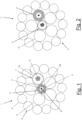
- Figure 1 schematically shows an overhead cable 1 according to a first embodiment of the present invention.
- the overhead cable 1 comprises, in a substantially central position, a first optical unit 2 comprising a first tube 2a housing at least one tight buffered optical fiber 3 suitable for sensing strain along the overhead cable.
- the position of the first optical unit 2 is in-axis, wherein the expression "in-axis" indicates that the longitudinal axis of the first optical unit 2 substantially coincides with the longitudinal axis of the overhead cable 1.
- the longitudinal axis of the overhead cable 1 is the axis along the lengthwise direction of the cable passing through its center. It is indicated in Figure 1 with letter "A".
- the first tube 2a is made of a metal, for example stainless steel (SST).
- the first tube 2a may be a longitudinally welded hermetically sealed SST tube.
- the first tube 2a may be made of longitudinally welded copper or aluminum.
- the first tube 2a may have an inner diameter comprised between 0.9 mm and 2.0 mm and an outer diameter comprised between 1.2 mm and 2.4 mm.
- the first tube 2a may have a thickness between 0.1 mm and 0.3 mm.
- the inner diameter may be equal to 1.5 mm and the outer diameter may be equal to 1.8 mm and hence the thickness may be equal to 0.15 mm.
- the first tube 2a may be made of two different metals.
- it can be made by a layer of SST rolled up and welded forming an internal metal tube, surrounded by a layer of a second metal, for example a layer of aluminum rolled up and welded forming an external metal tube.
- the first tube 2a may contain one, two or three tight buffered optical fibers.
- the tight buffered fiber(s) contained in the first tube 2a may have an outer diameter equal to 600 ⁇ m or 900 ⁇ m.
- Each optical fiber 3 inside the first tube 2a may be a single mode optical fiber compliant with ITU-T Recommendation G.652 (11/2016), G.654 (03/2020); G.655 (11/2009) or G.657 (11/2017), or a multimode optical fiber compliant with ITU-T Recommendation G.651.1 (11/2018).
- the at least one tight buffered optical fiber 3 is fixed to the inner surface of the first tube 2a.
- the at least one tight buffered optical fiber 3 is fixed to the inner surface of the first tube 2a along its whole length. In this way, the at least one tight buffered optical fiber 3 is mechanically congruent with the first tube 2a and then with the whole structure of the overhead cable 1. As already mentioned above, this leads to improving the sensing accuracy of the tight buffered fiber(s).
- Fixing is preferably performed by means of an adhesive compound or glue, for example a silicone adhesive or a two-components epoxy resin, which is applied longitudinally along the whole length of the first tube 2a and substantially fills the interstices between the tight buffered fiber(s) 3 and the inner surface of the first tube 2a.
- an adhesive compound or glue for example a silicone adhesive or a two-components epoxy resin, which is applied longitudinally along the whole length of the first tube 2a and substantially fills the interstices between the tight buffered fiber(s) 3 and the inner surface of the first tube 2a.
- the first optical unit 2 is surrounded by a layer 4 of a semi-conductive or conductive material.
- the layer 4 is a sheath radially outer the first tube 2a.
- the inner surface of the sheath 4 is in direct contact with the outer surface of the first tube 2a substantially along the whole length of the first tube 2a.
- the sheath 4 is made of aluminum and it is extruded over the first tube 2a.
- the sheath 4 may be an aluminum tube which is longitudinally welded and hermetically sealed.
- the thickness of the sheath 4 may be comprised between 0.1 mm and 2 mm.
- the sheath 4 is made of a semi-conductive material, for instance a semi-conductive polyethylene (PE) (for instance, linear low-density polyethylene, LLDPE, or low-density polyethylene, LDPE, or medium-density polyethylene, MDPE, or high-density polyethylene, HDPE) or semi-conductive cross-linked polyethylene (XLPE).
- PE semi-conductive polyethylene
- LLDPE linear low-density polyethylene
- LDPE low-density polyethylene
- LDPE low-density polyethylene
- LDPE low-density polyethylene
- MDPE low-density polyethylene
- HDPE high-density polyethylene
- XLPE semi-conductive cross-linked polyethylene
- the first optical unit 2 is surrounded by a third tube radially outer the first tube 2a and substantially concentric with the first tube 2a.
- the third tube may be of stainless steel.
- the third tube may be a longitudinally welded hermetically sealed SST tube.
- the third tube may have an inner diameter comprised between 1.2 mm and 5.4 mm and an outer diameter comprised between 1.8 mm and 6.0 mm.
- the thickness of the third tube is preferably comprised between 0.2 mm and 0.3 mm.
- the third tube may be welded on the first tube 2a.
- a conductive glue may be used between the first tube 2a and the third tube to guarantee the electrical contact between the first tube 2a and the third tube.
- the overhead cable 1 comprises an armor 5 which is provided around the sheath 4.
- the armor 5 comprises a plurality of round wires 6.
- the wires 6 are metal wires.
- the wires 6 are aluminum clad steel (ACS) wires.
- ACS aluminum clad steel
- they may be aluminum wires, aluminum alloy wires or galvanized steel wires.
- the armor may comprise a mix of these four types of wires.
- the diameter of each wire is comprised, for example, between 1.8 mm and 4.0 mm.
- the wires 6 of the armor 5 are circumferentially arranged around the first optical unit 2.
- the wires 6 of the armor electrically contact the outer surface of the sheath 4 surrounding the first optical unit 2.
- the wires 6 form a first layer of wires 6 radially outer the first optical unit 2 and a second layer of wires 6 radially outer the first layer of wires.
- the two layers of wires are circumferential layers that are substantially concentric with each other and with the first optical unit 2.
- the armor may comprise a single layer of wires around the first optical unit or three or more layers of wires around the first optical unit.
- the wires 6 are preferably helically stranded around the outer surface of the sheath 4.
- the wires 6 of the first layer may be laid in right direction around the first optical unit (right hand or Z lay) and the wires 6 of the second layer may then be stranded with a reverse lay direction.
- its wires may be stranded again in right direction, and so on.
- an anti-corrosion grease may be provided to fill the interstices between the first optical unit 2 and the armor wires 6 and among the armor wires 6, to avoid galvanic corrosion that may appear between dissimilar materials (aluminum and stainless-steel).
- the overhead cable 1 comprises a second optical unit 7 housing one or more optical fibers suitable for sensing the temperature.
- the second optical unit 7 comprises a second tube 7a comprising optical fibers 8 loosely arranged therein.
- the second tube 7a may be filled with a gel to provide protection against longitudinal water propagation and to protect the optical fiber(s) against hydrogen generation.
- the second optical unit 7 is located within the armor 5 in place of one metal wire.
- the second optical unit 7 is arranged within one of the layers of the armor 5.
- the second optical unit 7 is arranged within the first layer of wires 6 of the armor 5.
- the second tube 7a of the second optical unit 7 is made of a metal, for example stainless steel (SST).
- the second tube 7a may be a longitudinally welded hermetically sealed SST tube.
- the tube 7a may be made of longitudinally welded copper or aluminum.
- the second tube 7a may be made of two different metals.
- the second tube 7a may have an inner diameter comprised between 1.4 mm and 3.6 mm and an outer diameter comprised between 1.8 mm and 4.0 mm.
- the second tube 7a may be formed from an internal layer made of SST, for example a welded SST tube having an inner diameter comprised between 1.4 mm and 3.6 mm and an outer diameter comprised between 1.8 and 3.5 mm, and an external layer made of aluminum, for example a welded aluminum tube having a thickness comprised between 0.1 and 0.5 mm.
- SST an internal layer made of SST
- a welded SST tube having an inner diameter comprised between 1.4 mm and 3.6 mm and an outer diameter comprised between 1.8 and 3.5 mm
- an external layer made of aluminum for example a welded aluminum tube having a thickness comprised between 0.1 and 0.5 mm.
- the optical fibers 8 inside the second tube 7a may be single mode optical fibers compliant with ITU-T Recommendation G.652 (11/2016), G.654 (03/2020); G.655 (11/2009) or G.657 (11/2016), or multimode optical fibers compliant with ITU-T Recommendation G.651.1 (11/2018).
- the second tube 7a may contain a number of optical fibers comprised between 2 and 96, for instance equal to 24.
- the optical fibers 8 may have an extra length (EFL) lower than 0.5%.
- the presence of a layer of conductive or semi-conductive material around the first tube 2a allows adding at least one layer of semi-conductive or conductive material around the first optical unit 2 and increasing the diameter of the resulting unit to a value which is similar to the value of the diameter of the wires 6 of the armor (and the second optical unit).
- the first optical unit 2 may be assembled together with the metal wires 6 within the overhead cable 1.
- the first optical unit 2 is unable to move among the other elements of the overhead cable and is hence mechanically congruent with them. Any strain imparted on the cable similarly affects the first optical unit. This leads to improving the sensing accuracy.
- the material of the layer around the first optical unit 2 (in particular, between the first optical unit 2 and the armor 5) is conductive or semi-conductive, so as to guarantee the electrical contact between the first optical unit 2 and the armor 5 and avoid the presence of an electrical current which may be induced in the first optical unit 2.
- FIG. 2 schematically shows an overhead cable 1' according to a second embodiment of the present invention.
- the overhead cable 1' comprises a first optical unit 2' comprising a first tube with the at least one tight buffered optical fiber arranged therein and surrounded by a layer of a semiconductive or conductive material, and a second optical unit 7' comprising a second tube with one or more loose optical fiber.
- the overhead cable 1' also comprises an armor 5'.
- the structures of the first optical unit and the second optical unit are the same as already described above.
- the first optical unit 2' is off-axis, wherein the expression "off-axis" indicates that the longitudinal axis of the first optical unit 2' does not coincide with the longitudinal axis of the overhead cable 1'.
- the second optical unit 7' is located in-axis at the center of the cable and the first optical unit 2' is located within the armor (in particular, within a first layer of wires 6' radially outer the second tube).
- the first optical unit 2' is stranded with the same pitch as the wires 6' of the first layer of the armor.
- the first optical unit and the second optical unit may be both located off-axis.
- each of the first optical unit and the second optical unit may be located within any one of the layers of wires of the armor and a metal wire may be located at the center of the cable.
- the first optical unit when the first optical unit is provided off-axis, an extra length is required for the first optical unit, as in this case the first optical unit is stranded around the central unit (for instance, in the embodiment shown in Figure 2 the central unit is the second optical unit).
- the extra length which is required may be between 1% and 4%. It is worth to point out here, that, if the first optical unit is located off-axis with an additional extra-length, the length of the cable will not match the length of the first optical unit, so that, for strain measurement, suitable calculations will be required to match the two lengths.
- Figure 3 schematically shows an overhead cable 10 according to a third embodiment of the present invention.
- the overhead cable 10 comprises, in a central position, a first optical unit 11 and a second optical unit 12.
- the first optical unit 11 and the second optical unit 12 are laid substantially parallel to the longitudinal axis of the overhead cable 10 and located substantially at the center of the cable 10.
- the first optical unit 11 and the second optical unit 12 are stranded together.
- the first optical unit 11 comprises a first tube 11a comprising at least one tight buffered optical fiber 13
- the second optical unit 12 comprises a second tube 12a and one or more loose optical fibers 14, as already described above.
- the overhead cable 10 preferably comprises also a semi-conductive material collectively surrounding the first optical unit 11 and the second optical unit 12.
- the overhead cable 10 comprises a cover 15 embedding the first optical unit 11 and the second optical unit 12.
- the material of the cover 15 substantially fills the space between the first optical unit 11 and the second optical unit 12 and surrounds both of them.
- the cover 15 is made of a semi-conductive material, for instance a semi-conductive polyethylene (PE) (for instance, linear low-density polyethylene, LLDPE, or low-density polyethylene, LDPE, or medium-density polyethylene, MDPE, or high-density polyethylene, HDPE) or semi-conductive cross-linked polyethylene (XLPE).
- PE semi-conductive polyethylene
- the outer diameter of the cover 15 is comprised between 3 mm and 10 mm.
- the overhead cable 10 preferably comprises a third tube 16 radially outer the cover 15.
- the third tube 16 is a metal tube, such as, for instance, a tube made of aluminum.
- the third tube 16 may be extruded over the cover 15 or it may be a longitudinally welded hermetically sealed aluminum tube whose inner surface is in electrical contact with the outer surface of the cover 15.
- the third tube 16 may have an outer diameter comprised between 6 mm and 14 mm.
- the overhead cable 10 also comprises an armor 17 which is provided around the third tube 16, the armor 17 comprising a plurality of wires 18 as already described above.
- the armor 17 shown in Figure 3 comprises a plurality of wires 18 arranged in a single circumferential layer which is substantially concentric with the third tube 16, the wires being preferably helically wound around the outer surface of the third tube 16 in electrical contact with it.
- the armor 17 may comprise a plurality of circumferential layers of wires around the third tube 16.
- Figure 4 schematically shows an overhead cable 20 according to a fourth embodiment of the present invention.
- the overhead cable 20 comprises, in a central position, a first optical unit 21 and a second optical unit 22.
- the first optical unit 21 and the second optical unit 22 are laid substantially parallel to the longitudinal axis of the overhead cable 20 and located substantially at the center of the cable 20.
- the first optical unit 21 comprises a first tube 21a comprising at least one tight buffered optical fiber 23 as already described above.
- the second optical unit 22 preferably comprises a second tube 22a and one or more loose optical fibers 24 as already described above.
- the overhead cable 20 preferably comprises a third tube 25 collectively surrounding both the first optical unit 21 and the second optical unit 22.
- the third tube 25 is a metal tube, for example, a tube made of stainless steel.
- the third tube 25 may also be made of copper.
- the third tube 25 may be a laser welded hermetically sealed SST tube.
- the third tube 25 may have an outer diameter comprised between 3 mm and 6 mm and a thickness between 0.2 mm and 0.3 mm.
- the overhead cable 20 preferably comprises a semi-conductive material interposed between the first optical unit 21, the second optical unit 22 and the third tube 25, in particular between the outer surface of both the first tube 21a and the second tube 22a and the inner surface of the third tube 25 to assure electrical contact between the different metal tubes.
- the overhead cable 20 comprises a semi-conductive adhesive compound 26 such as, for instance, a semi-conductive glue, filling at least partially the interstices between the first optical unit 21 and the second optical unit 22 and between each of the first optical unit 21 and the second optical unit 22 and the inner surface of the third tube 25 to assure electrical contact between the optical units and each optical unit and the third tube.
- the adhesive compound 26 allows fixing the first optical unit 21 to the inner surface of the third tube 25. In this way, the first optical unit 21 is mechanically congruent with the overhead cable 20.
- the overhead cable 20 comprises a fourth tube 27 surrounding the third tube 25 and electrically contacting the outer surface thereof.
- the fourth tube 27 is a metal tube, preferably a tube made of aluminum, which is extruded over the third tube 25.
- the fourth tube is a longitudinally welded aluminum tube whose inner surface electrically contacts the outer surface of the third tube 25.
- the fourth tube 27 may have an outer diameter comprised between 6 mm and 14 mm and a thickness between 1 and 3mm.
- the overhead cable 20 comprises an armor 28 which is provided around the fourth tube 27, the armor 28 comprising a plurality of wires 29 as already described above.
- the armor 28 shown in Figure 4 comprises a plurality of wires 29 arranged in a single circumferential layer which is substantially concentric with the fourth tube 27, the wires being preferably helically wound around the outer surface of the fourth tube 27 in electrical contact with it.
- the armor may comprise a plurality of circumferential layers of wires around the fourth tube 27.
- Figure 5 schematically shows an overhead cable 30 according to a fifth embodiment of the present invention.
- the overhead cable 30 comprises, in a central position, a first optical unit 31 and a second optical unit 32.
- the first optical unit 31 and the second optical unit 32 are laid substantially parallel to the longitudinal axis of the overhead cable 30 and located substantially at the center of the cable 30.
- the first optical unit 31 and the second optical unit 32 are stranded together.
- the first optical unit 31 comprises a first tube 31a comprising at least one tight buffered optical fiber 33
- the second optical unit 32 comprises a second tube 32a and one or more loose optical fibers 34, as already described above.
- the overhead cable 30 preferably comprises also a semi-conductive material collectively surrounding the first optical unit 31 and the second optical unit 32.
- the overhead cable 30 comprises a cover 35 of a semi-conductive material embedding the first optical unit 31 and the second optical unit 32 as already described above with reference to the third embodiment of the present invention.
- the overhead cable 30 comprises an armor 36 which is provided around the cover 35, the armor 36 comprising a plurality of wires 37 as already described above.
- the armor 36 shown in Figure 5 comprises a plurality of wires 37 arranged in two circumferential layers, the wires 37 being preferably helically wound around the outer surface of the cover 35 in electrical contact with it.
- the armor may comprise one or more circumferential layers of wires.
- Figure 6 schematically shows an overhead cable 40 according to a sixth embodiment of the present invention.
- the overhead cable 40 comprises, in a central position, a first optical unit 41 and a second optical unit 42.
- the first optical unit 41 and the second optical unit 42 are laid substantially parallel to the longitudinal axis of the overhead cable 40 and located substantially at the center of the cable 40.
- the first optical unit 41 and the second optical unit 42 are stranded together.
- the first optical unit 41 comprises a first tube 41a comprising at least one tight buffered optical fiber 43 as already described above.
- the second optical unit 42 comprises a second tube 42a and one or more loose optical fibers 44 as already described above.
- the overhead cable 40 preferably comprises a third tube 45 collectively surrounding both the first optical unit 41 and the second optical unit 42, as already described above with reference to the fourth embodiment of the present invention.
- the overhead cable 40 also comprises a semi-conductive material interposed between the first optical unit 41, the second optical unit 42 and the third tube 45.
- the semi-conductive material is interposed the outer surface of both the first tube 41a and the second tube 42a and the inner surface of the third tube 45 to assure electrical contact between the different metal tubes.
- the overhead cable 40 comprises a semi-conductive adhesive compound 46 which fills at least partially the interstices between the first optical unit 41 and the second optical unit 42 and between each of the first optical unit and the second optical unit and the inner surface of the third tube 45 to assure electrical contact between the optical units and each optical unit and the third tube.
- the adhesive compound 46 allows fixing the first optical unit 41 to the inner surface of the third tube 45. In this way, the first optical unit 41 is mechanically congruent with the overhead cable 40.
- the overhead cable 40 comprises an armor 47 which is provided around the third tube 45, the armor 47 comprising a plurality of wires 48 as already described above.
- the armor 47 shown in Figure 6 comprises a plurality of wires 48 arranged in two circumferential layers, the wires being preferably helically wound around the outer surface of the third tube 45 in electrically contact with it.
- Figure 7 schematically shows a measurement system 70 for measuring strain along an overhead power transmission line by means of the distributed fiber optic sensing system of the optical cable described herein above.
- the measurement system comprises a measuring unit 71 connected to an overhead cable 72 according to an embodiment of the present invention.
- the measuring unit 71 comprises a light emitter (e.g., a laser operating at 1550 nm) for sending signals into the at least one thigh buffered optical fiber of the first optical unit and the one or more loose optical fibers of the second optical unit.
- the measuring unit 71 also comprises a light receiver (e.g., a photodetector) for detecting signals coming from said at least one thigh buffered optical fiber of the first optical unit and said one or more loose optical fibers of the second optical unit and measuring strain and temperature along the cable.
- the operation of the measurement system 70 may be based, as known, on the Stimulated Brillouin Backscattering (SBS).
- the measuring unit 71 may be a known Brillouin Optical Time Domain Analyzer or BOTDA such as, for instance, the VISION Interrogator manufactured by Omnisens SA, Switzerland.
Landscapes
- Physics & Mathematics (AREA)
- General Physics & Mathematics (AREA)
- Communication Cables (AREA)
Abstract
It is disclosed a cable for an overhead power transmission line, the cable comprising: a first optical unit comprising a first metal tube housing at least one an optical fiber suitable for sensing strain, the at least one optical fiber in the first metal tube being a tight buffered optical fiber fixed to an inner surface of the first metal tube; a second optical unit comprising a second metal tube comprising one or more loose optical fibers suitable for sensing temperature; and an armor comprising one or more layers of metal wires. The first optical unit is surrounded by at least one layer of semi-conductive or conductive material electrically contacting the outer surface of the first metal tube.
Description
- The present invention relates to the field of medium and high voltage overhead power transmission lines. In particular, the present invention relates to a cable for an overhead power transmission line including a distributed fiber optic sensing system.
- In an overhead power transmission line both phase conductors and ground conductors may include optical elements for data transmission. In particular, an OPPC (Optical Phase Conductor) is a cable including an optical unit (including one or more optical fibers) for data transmission and a metallic armor made of stranded wires for electrical power transmission and mechanical support. An OPGW (Optical Ground Wire) is a cable including an optical unit for data transmission and a metallic armor commonly set at ground potential, and it is typically suspended above the phase conductors. The optical unit is typically a metal tube where one or more optical fibers are encapsulated.
- An exemplary OPGW is disclosed in
EP 1210633 B1 . - In particular,
EP 1210633 B1 discloses an electric conductor incorporating at least one optical fiber and having a central axial element with at least one layer of elements helically stranded about it. At least one of the elements, preferably the central axial one, includes at least one optical fiber which is enclosed in a longitudinally extending welded metal tube (typically stainless steel). A second metal tube of greater thickness and higher conductivity than the welded metal tube and having an unwelded longitudinal seam surrounds the welded tube. The second tube is typically of aluminum and serves to increase the diameter of the element so that a greater range of useful conductor sizes can be formed by using it in conjunction with appropriately chosen wire diameters. - As known, optical fibers may be used also for sensing purposes along a cable. Indeed, Distributed Fiber Optic Sensing (DFOS) systems transform an optical fiber contained in a cable into a continuous sensor capable of monitor physical parameters such as the temperature or strain. In particular, temperature can be measured by means of a so-called DTS (Distributed Temperature Sensing) system, which is based, for example, on Raman or Brillouin scattering, while strain may be measured by means of a so-called DSS (Distributed Strain Sensing) system, which is commonly based on Brillouin scattering.
-
EP 4024106 A1 discloses an optical cable for distributed sensing suitable for underground, underwater and/or submarine applications. The optical cable comprises a first metal tube with at least two optical fibers loosely arranged therein and a second metal tube with at least two tight buffered optical fibers tightly arranged within an inner surface of the second metal tube. A third metal tube having an inner surface collectively surrounds and operatively contacts the first metal tube and said second metal tube. At least one of the first metal tube and the second metal tube is fixed by means of an adhesive compound to the inner surface of the third metal tube. - In a cable of an overhead power transmission line, strain measurements provide important indications about usage of the cable. In OPGW cables, strain measurements may be used for determining the effect on the ground conductor of external stresses due to, for instance, weather conditions (e.g., ice, strong winds, etc.). In phase conductors, strain and temperature measurements may be used to evaluate mechanical stresses and determine more precisely the maximum current rating that is applicable to the transmission line.
-
CN 111609807A discloses a power transmission line dynamic deformation reconstruction method based on OPGW multi-core stress sensing. The method comprises the steps of selecting a plurality of optical fibers in an OPGW optical cable as optical fibers in a static state; respectively measuring the stress of each selected optical fiber in a natural suspension state by using a distributed optical fiber stress sensing system; calculating the coupling coefficient of each selected optical fiber to the same external disturbance according to the stress of each selected optical fiber in the natural suspension state; determining the correction stress of each selected optical fiber according to the measurement result of the stress dynamic distribution condition of each selected optical fiber and the coupling coefficient of the corresponding selected optical fiber; and constructing a three-dimensional form of the OPGW optical cable according to the shape restoration formula and the correction stress of each selected optical fiber so as to realize reconstruction of the dynamic deformation of the corresponding power transmission line and improve the accuracy of the dynamic deformation of the power transmission line obtained by reconstruction. - The Applicant perceived the need to provide a cable for an overhead power transmission line (in particular, but not exclusively, an OPGW or OPPC cable) which provides an accurate and reliable strain distributed measurement all along the cable length.
- In this respect,
CN 111609807A provides for measuring the stress of a number of optical fibers in an OPGW cable to reconstruct a dynamic deformation of the cable. However, the inventors noticed that the position of the optical cores used inCN 111609807 A may vary inside the tubes in which the optical fibers are arranged (seeFigure 3 ofCN 111609807 A ). This may lead to a loss of sensing accuracy and reliability in the strain measurement. - Moreover, it is to be noticed that, as known, the Brillouin frequency shift in an optical fiber depends on strain and temperature. Therefore, any strain measurement based on the Brillouin scattering need to be adjusted to compensate the effect of the temperature dependency of the Brillouin frequency shift.
- In view of the above, the Applicant has tackled the problem of providing a cable for an overhead power transmission line (in particular, but not exclusively, an OPGW or OPPC cable) which allows improving the accuracy and reliability of the strain measurement. In particular, the Applicant has tackled the problem of providing a cable for an overhead power transmission line (in particular, but not exclusively, an OPGW or OPPC cable) provided with a distributed fiber optic sensing system wherein the one or more optical fibers used to measure the strain are mechanically congruent with the whole structure of the cable so as to achieve a higher sensing accuracy, and wherein other optical fibers, substantially not affected by strain, are provided for sensing the temperature so as to compensate the influence of temperature in the strain sensing.
- The inventors found that the problem above may be solved by providing a multisensing cable for an overhead power transmission line, which comprises a distributed fiber optic sensing system allowing to measure strain and temperature along the cable. In particular, the distributed fiber optic sensing system of the multisensing cable comprises:
- a first optical unit comprising a first metal tube housing at least one optical fiber suitable for sensing strain, the optical fiber in the first metal tube being a tight buffered optical fiber fixed to an inner surface of the first metal tube;
- a second optical unit comprising a second metal tube comprising one or more loose optical fibers suitable for sensing temperature; and
- an armor of metal wires,
- As a matter of fact, the multisensing cable of the present invention is provided with a first optical unit with at least one optical fiber tightly buffered inside a metal tube and fixed to the inner surface of the tube, the first optical unit being in turn tightly accommodated in the cable so that the tight buffered fiber is mechanically congruent with the whole structure of the cable and guarantees a high sensing accuracy for the strain measurement. The tight accommodation of the first optical unit in the cable can be accomplished by adding at least one layer of a semi-conductive or conductive material around the first optical unit and thus increasing the diameter of the resulting unit to a value which is similar to the value of the diameter of the metal wires of the cable. In this way, the first optical unit may be assembled in the cable with the metal wires in such a way that it is substantially unable to move. Moreover, the presence of the semi-conductive or conductive material around the first optical unit (and, in particular, between the first optical unit and the cable metal wires) allows avoiding the occurrence of induced currents in the first optical unit.
- The higher sensing accuracy is also achieved by providing the cable with a second optical unit with loose optical fibers suitable to measure the temperature, so as to compensate the effect of the temperature dependency of the Brillouin frequency shift.
- In the following description and in the claims, the expression "overhead cable" will be used to refer to a cable for an overhead power transmission line according to the present invention.
- The expression "optical fiber" is meant to indicate an optical glass core surrounded by a glass cladding and a coating system comprising one or two layers of cured resins, for example acrylate resins, optionally provided with a coloured ink layer. The optical fibers may be single mode or multimode optical fibers with a nominal diameter between about 180 µm and 250 µm. Moreover, the expression "tight buffered optical fiber" will indicate an optical fiber comprising an additional buffer layer of a polymer material around the coating. A tight buffered optical fiber may have an outer diameter between 400 and 1200um. Typical values for the outer diameter are from 600 µm to 900 µm.
- Moreover, the expression "loose optical fibers" will indicate optical fibers that are loosely contained inside a tube. In this case the tube is also referred to "loose tube".
- In the following description and in the claims, the adjective "conductive" will be used to indicate "electrically conductive".
- The adjective "conductive" or "semi-conductive" referred to objects or materials should be read according to the well-known technical meaning. A material is commonly considered conductive if its electrical resistivity is lower than 10-4 Ω*m at 20 °C. A material is commonly considered semi-conductive if its electrical resistivity is comprised between than 10-4 Ω*m and 107 Ω*m at 20 °C. Most common semi-conductive material employed in medium and high voltage overhead power transmission lines has an electrical resistivity comprised between than 10-4 Ω*m and 102 Ω*m at 20 °C.
- The expression "being in electrical contact" referred to two or more conductive or semi-conductive objects will indicate that said two or more conductive or semi-conductive objects are in direct contact with each other or in indirect contact with each other through one or more conductive or semi-conductive elements interposed therebetween, which comprise one or more elements in direct contact with said objects, wherein said elements provide a continuity of conductive or semi-conductive material(s) between said objects. From this, it follows that, in operating overhead power transmission lines, two or more conductive or semi-conductive objects which are in electrical contact will be substantially at the same voltage.
- In one aspect, the present invention relates to a cable for an overhead power transmission line, the cable comprising:
- a first optical unit comprising a first metal tube housing at least one optical fiber suitable for sensing strain, said at least one optical fiber in the first metal tube being a tight buffered optical fiber fixed to an inner surface of the first metal;
- a second optical unit comprising a second metal comprising one or more loose optical fibers suitable for sensing temperature; and
- an armor comprising one or more layers of metal wires,
- Preferably, the first metal tube of the first optical unit is in electrical contact with the armor.
- Preferably, the first metal tube and the second metal tube are made of stainless steel.
- Preferably, the tight buffered optical fiber is fixed to the inner surface of the first metal tube by means of an adhesive compound.
- According to an embodiment of the present invention, the first optical unit is individually surrounded by an aluminum tube.
- According to another embodiment of the present invention, the first optical unit is individually surrounded by a sheath made of semi-conductive polyethylene or semi-conductive cross-linked polyethylene.
- According to embodiments of the present invention, the first optical unit is located substantially at the center of the cable.
- According to other embodiments of the present invention, the first optical unit is located within the armor in place of a metal wire.
- Preferably, the cable further comprises an anti-corrosion grease.
- According to embodiments of the present invention, the first optical unit and said second optical unit are collectively surrounded by a semi-conductive cover embedding the first optical unit and the second optical unit. Preferably, the cover is made of semi-conductive polyethylene or semi-conductive cross-linked polyethylene. Preferably, the cable further comprises a third tube surrounding the cover, the third metal tube being an aluminum tube.
- According to embodiments of the present invention, said first optical unit and said second optical unit are collectively surrounded by a third metal tube and wherein a semi-conductive material is interposed between said first optical unit, said second optical unit and said third metal tube, said semi-conductive material contacting the outer surface of both the first tube and the second tube and the inner surface of the third tube. Preferably, the semi-conductive material is a semi-conductive adhesive compound. Preferably, the cable further comprises a fourth metal tube surrounding the third metal tube, the fourth metal tube being an aluminum tube.
- In another aspect, the present invention relates to a measurement system for measuring strain along an overhead power transmission line, the measurement system comprising a measuring unit and a cable as set forth above.
- Further characteristics and advantages will become more apparent by reading the following detailed description of embodiments given as examples with reference to the accompanying drawings (which are not on scale), wherein:
-
Figure 1 schematically shows a cross section of an overhead cable according to a first embodiment of the present invention; -
Figure 2 schematically shows a cross section of an overhead cable according to a second embodiment of the present invention; -
Figure 3 schematically shows a cross section of an overhead cable according to a third embodiment of the present invention; -
Figure 4 schematically shows a cross section of an overhead cable according to a fourth embodiment of the present invention; and -
Figure 5 schematically shows a cross section of an overhead cable according to a fifth embodiment of the present invention; and -
Figure 6 schematically shows a cross section of an overhead cable according to a sixth embodiment of the present invention; and -
Figure 7 schematically shows a measurement system according to the present invention. - In the present description and claims, unless otherwise specified, all the numbers and values should be intended as preceded by the term "about". Also, all ranges include any combination of the maximum and minimum points disclosed and include any intermediate ranges therein, which may or may not be specifically enumerated herein.
- It is to be noticed that any embodiment described herein below relates to a cable suitable to be installed in an overhead power transmission line. In particular, any overhead cable according to the embodiments of the present invention may be an OPGW (Optical Ground Wire), MASS (Metallic Aereal Self Supported) or OPPC (Optical Phase Conductor) cable. Indeed, each overhead cable presented herein after comprises a central unit possibly comprising optical fibers and an armor radially outer the central unit and helically stranded around it, the armor comprising one or more layers of metal wires configured to withstand the passage of electrical current. In case of an OPCC, the armor is configured to sustain electrical current for power transmission, while in an OPGW the armor is configured to shield the conductors of the overhead power transmission line, creating a zero potential on top of the overhead power transmission line, and/or to permit the passage of electrical current in specific cases, such as lightning strikes, arc discharges, or short-circuits.
-
Figure 1 schematically shows anoverhead cable 1 according to a first embodiment of the present invention. - The
overhead cable 1 comprises, in a substantially central position, a firstoptical unit 2 comprising afirst tube 2a housing at least one tight bufferedoptical fiber 3 suitable for sensing strain along the overhead cable. According to this first embodiment, the position of the firstoptical unit 2 is in-axis, wherein the expression "in-axis" indicates that the longitudinal axis of the firstoptical unit 2 substantially coincides with the longitudinal axis of theoverhead cable 1. The longitudinal axis of theoverhead cable 1 is the axis along the lengthwise direction of the cable passing through its center. It is indicated inFigure 1 with letter "A". - The
first tube 2a is made of a metal, for example stainless steel (SST). In particular, thefirst tube 2a may be a longitudinally welded hermetically sealed SST tube. In other embodiments, thefirst tube 2a may be made of longitudinally welded copper or aluminum. Thefirst tube 2a may have an inner diameter comprised between 0.9 mm and 2.0 mm and an outer diameter comprised between 1.2 mm and 2.4 mm. Thefirst tube 2a may have a thickness between 0.1 mm and 0.3 mm. For example, the inner diameter may be equal to 1.5 mm and the outer diameter may be equal to 1.8 mm and hence the thickness may be equal to 0.15 mm. - In some embodiments, the
first tube 2a may be made of two different metals. For example, it can be made by a layer of SST rolled up and welded forming an internal metal tube, surrounded by a layer of a second metal, for example a layer of aluminum rolled up and welded forming an external metal tube. - According to embodiments of the present invention, the
first tube 2a may contain one, two or three tight buffered optical fibers. The tight buffered fiber(s) contained in thefirst tube 2a may have an outer diameter equal to 600 µm or 900 µm. Eachoptical fiber 3 inside thefirst tube 2a may be a single mode optical fiber compliant with ITU-T Recommendation G.652 (11/2016), G.654 (03/2020); G.655 (11/2009) or G.657 (11/2016), or a multimode optical fiber compliant with ITU-T Recommendation G.651.1 (11/2018). - The at least one tight buffered
optical fiber 3 is fixed to the inner surface of thefirst tube 2a. For example, the at least one tight bufferedoptical fiber 3 is fixed to the inner surface of thefirst tube 2a along its whole length. In this way, the at least one tight bufferedoptical fiber 3 is mechanically congruent with thefirst tube 2a and then with the whole structure of theoverhead cable 1. As already mentioned above, this leads to improving the sensing accuracy of the tight buffered fiber(s). Fixing is preferably performed by means of an adhesive compound or glue, for example a silicone adhesive or a two-components epoxy resin, which is applied longitudinally along the whole length of thefirst tube 2a and substantially fills the interstices between the tight buffered fiber(s) 3 and the inner surface of thefirst tube 2a. - The first
optical unit 2 is surrounded by a layer 4 of a semi-conductive or conductive material. In particular, according to this first embodiment, the layer 4 is a sheath radially outer thefirst tube 2a. The inner surface of the sheath 4 is in direct contact with the outer surface of thefirst tube 2a substantially along the whole length of thefirst tube 2a. According to an embodiment, the sheath 4 is made of aluminum and it is extruded over thefirst tube 2a. Alternatively, the sheath 4 may be an aluminum tube which is longitudinally welded and hermetically sealed. The thickness of the sheath 4 may be comprised between 0.1 mm and 2 mm. - According to alternative embodiments of the present invention, the sheath 4 is made of a semi-conductive material, for instance a semi-conductive polyethylene (PE) (for instance, linear low-density polyethylene, LLDPE, or low-density polyethylene, LDPE, or medium-density polyethylene, MDPE, or high-density polyethylene, HDPE) or semi-conductive cross-linked polyethylene (XLPE). In this case, preferably, the thickness of the sheath 4 may be comprised between 0.4 mm and 3 mm.
- According to even alternative embodiments of the present invention not shown in the drawings, the first
optical unit 2 is surrounded by a third tube radially outer thefirst tube 2a and substantially concentric with thefirst tube 2a. The third tube may be of stainless steel. In particular, the third tube may be a longitudinally welded hermetically sealed SST tube. The third tube may have an inner diameter comprised between 1.2 mm and 5.4 mm and an outer diameter comprised between 1.8 mm and 6.0 mm. The thickness of the third tube is preferably comprised between 0.2 mm and 0.3 mm. According to these embodiments, the third tube may be welded on thefirst tube 2a. Alternatively, a conductive glue may be used between thefirst tube 2a and the third tube to guarantee the electrical contact between thefirst tube 2a and the third tube. - According to the first embodiment of the present invention as shown in
Figure 1 , theoverhead cable 1 comprises anarmor 5 which is provided around the sheath 4. Thearmor 5 comprises a plurality ofround wires 6. Thewires 6 are metal wires. For example, thewires 6 are aluminum clad steel (ACS) wires. Alternatively, they may be aluminum wires, aluminum alloy wires or galvanized steel wires. The armor may comprise a mix of these four types of wires. The diameter of each wire is comprised, for example, between 1.8 mm and 4.0 mm. - According to embodiments of the present invention, the
wires 6 of thearmor 5 are circumferentially arranged around the firstoptical unit 2. In particular, thewires 6 of the armor electrically contact the outer surface of the sheath 4 surrounding the firstoptical unit 2. According to the embodiment shown inFigure 1 , thewires 6 form a first layer ofwires 6 radially outer the firstoptical unit 2 and a second layer ofwires 6 radially outer the first layer of wires. The two layers of wires are circumferential layers that are substantially concentric with each other and with the firstoptical unit 2. According to other embodiments non shown in the Figures, the armor may comprise a single layer of wires around the first optical unit or three or more layers of wires around the first optical unit. Thewires 6 are preferably helically stranded around the outer surface of the sheath 4. In particular, thewires 6 of the first layer may be laid in right direction around the first optical unit (right hand or Z lay) and thewires 6 of the second layer may then be stranded with a reverse lay direction. In case a third layer is present, its wires may be stranded again in right direction, and so on. - Optionally, when required, an anti-corrosion grease may be provided to fill the interstices between the first
optical unit 2 and thearmor wires 6 and among thearmor wires 6, to avoid galvanic corrosion that may appear between dissimilar materials (aluminum and stainless-steel). - According to the present invention, the
overhead cable 1 comprises a secondoptical unit 7 housing one or more optical fibers suitable for sensing the temperature. The secondoptical unit 7 comprises asecond tube 7a comprising optical fibers 8 loosely arranged therein. Thesecond tube 7a may be filled with a gel to provide protection against longitudinal water propagation and to protect the optical fiber(s) against hydrogen generation. According to the first embodiment of the present invention illustrated inFigure 1 , the secondoptical unit 7 is located within thearmor 5 in place of one metal wire. In particular, the secondoptical unit 7 is arranged within one of the layers of thearmor 5. According to the embodiment shown inFigure 1 , the secondoptical unit 7 is arranged within the first layer ofwires 6 of thearmor 5. - The
second tube 7a of the secondoptical unit 7 is made of a metal, for example stainless steel (SST). In particular, thesecond tube 7a may be a longitudinally welded hermetically sealed SST tube. In other embodiments, thetube 7a may be made of longitudinally welded copper or aluminum. In some embodiments, thesecond tube 7a may be made of two different metals. Thesecond tube 7a may have an inner diameter comprised between 1.4 mm and 3.6 mm and an outer diameter comprised between 1.8 mm and 4.0 mm. As one alternative, thesecond tube 7a may be formed from an internal layer made of SST, for example a welded SST tube having an inner diameter comprised between 1.4 mm and 3.6 mm and an outer diameter comprised between 1.8 and 3.5 mm, and an external layer made of aluminum, for example a welded aluminum tube having a thickness comprised between 0.1 and 0.5 mm. - The optical fibers 8 inside the
second tube 7a may be single mode optical fibers compliant with ITU-T Recommendation G.652 (11/2016), G.654 (03/2020); G.655 (11/2009) or G.657 (11/2016), or multimode optical fibers compliant with ITU-T Recommendation G.651.1 (11/2018). According to embodiments of the present invention, thesecond tube 7a may contain a number of optical fibers comprised between 2 and 96, for instance equal to 24. The optical fibers 8 may have an extra length (EFL) lower than 0.5%. - The skilled person will appreciate that the presence of a layer of conductive or semi-conductive material around the
first tube 2a allows adding at least one layer of semi-conductive or conductive material around the firstoptical unit 2 and increasing the diameter of the resulting unit to a value which is similar to the value of the diameter of thewires 6 of the armor (and the second optical unit). In this way, the firstoptical unit 2 may be assembled together with themetal wires 6 within theoverhead cable 1. As a matter of fact, the firstoptical unit 2 is unable to move among the other elements of the overhead cable and is hence mechanically congruent with them. Any strain imparted on the cable similarly affects the first optical unit. This leads to improving the sensing accuracy. - Profitably, the material of the layer around the first optical unit 2 (in particular, between the first
optical unit 2 and the armor 5) is conductive or semi-conductive, so as to guarantee the electrical contact between the firstoptical unit 2 and thearmor 5 and avoid the presence of an electrical current which may be induced in the firstoptical unit 2. -
Figure 2 schematically shows an overhead cable 1' according to a second embodiment of the present invention. The overhead cable 1' comprises a first optical unit 2' comprising a first tube with the at least one tight buffered optical fiber arranged therein and surrounded by a layer of a semiconductive or conductive material, and a second optical unit 7' comprising a second tube with one or more loose optical fiber. The overhead cable 1' also comprises an armor 5'. The structures of the first optical unit and the second optical unit are the same as already described above. In the overhead cable 1', the first optical unit 2' is off-axis, wherein the expression "off-axis" indicates that the longitudinal axis of the first optical unit 2' does not coincide with the longitudinal axis of the overhead cable 1'. In particular, the second optical unit 7' is located in-axis at the center of the cable and the first optical unit 2' is located within the armor (in particular, within a first layer of wires 6' radially outer the second tube). The first optical unit 2' is stranded with the same pitch as the wires 6' of the first layer of the armor. - According to other embodiments of the present invention not shown in the Figures, the first optical unit and the second optical unit may be both located off-axis. In these cases, each of the first optical unit and the second optical unit may be located within any one of the layers of wires of the armor and a metal wire may be located at the center of the cable.
- It is to be noticed that when the first optical unit is provided off-axis, an extra length is required for the first optical unit, as in this case the first optical unit is stranded around the central unit (for instance, in the embodiment shown in
Figure 2 the central unit is the second optical unit). The extra length which is required may be between 1% and 4%. It is worth to point out here, that, if the first optical unit is located off-axis with an additional extra-length, the length of the cable will not match the length of the first optical unit, so that, for strain measurement, suitable calculations will be required to match the two lengths. -
Figure 3 schematically shows anoverhead cable 10 according to a third embodiment of the present invention. - The
overhead cable 10 comprises, in a central position, a firstoptical unit 11 and a secondoptical unit 12. In some embodiments, the firstoptical unit 11 and the secondoptical unit 12 are laid substantially parallel to the longitudinal axis of theoverhead cable 10 and located substantially at the center of thecable 10. In other embodiments the firstoptical unit 11 and the secondoptical unit 12 are stranded together. - Preferably, the first
optical unit 11 comprises afirst tube 11a comprising at least one tight bufferedoptical fiber 13, and the secondoptical unit 12 comprises asecond tube 12a and one or more looseoptical fibers 14, as already described above. - The
overhead cable 10 preferably comprises also a semi-conductive material collectively surrounding the firstoptical unit 11 and the secondoptical unit 12. In particular, according to this embodiment, theoverhead cable 10 comprises acover 15 embedding the firstoptical unit 11 and the secondoptical unit 12. The material of thecover 15 substantially fills the space between the firstoptical unit 11 and the secondoptical unit 12 and surrounds both of them. Thecover 15 is made of a semi-conductive material, for instance a semi-conductive polyethylene (PE) (for instance, linear low-density polyethylene, LLDPE, or low-density polyethylene, LDPE, or medium-density polyethylene, MDPE, or high-density polyethylene, HDPE) or semi-conductive cross-linked polyethylene (XLPE). Preferably, the outer diameter of thecover 15 is comprised between 3 mm and 10 mm. - The
overhead cable 10 preferably comprises athird tube 16 radially outer thecover 15. Thethird tube 16 is a metal tube, such as, for instance, a tube made of aluminum. In particular, thethird tube 16 may be extruded over thecover 15 or it may be a longitudinally welded hermetically sealed aluminum tube whose inner surface is in electrical contact with the outer surface of thecover 15. Thethird tube 16 may have an outer diameter comprised between 6 mm and 14 mm. - According to this embodiment of the present invention, the
overhead cable 10 also comprises anarmor 17 which is provided around thethird tube 16, thearmor 17 comprising a plurality ofwires 18 as already described above. Thearmor 17 shown inFigure 3 comprises a plurality ofwires 18 arranged in a single circumferential layer which is substantially concentric with thethird tube 16, the wires being preferably helically wound around the outer surface of thethird tube 16 in electrical contact with it. According to other embodiments, thearmor 17 may comprise a plurality of circumferential layers of wires around thethird tube 16. -
Figure 4 schematically shows anoverhead cable 20 according to a fourth embodiment of the present invention. - The
overhead cable 20 comprises, in a central position, a firstoptical unit 21 and a second optical unit 22. Preferably, the firstoptical unit 21 and the second optical unit 22 are laid substantially parallel to the longitudinal axis of theoverhead cable 20 and located substantially at the center of thecable 20. - Preferably, the first
optical unit 21 comprises afirst tube 21a comprising at least one tight bufferedoptical fiber 23 as already described above. The second optical unit 22 preferably comprises asecond tube 22a and one or more looseoptical fibers 24 as already described above. - The
overhead cable 20 preferably comprises athird tube 25 collectively surrounding both the firstoptical unit 21 and the second optical unit 22. Thethird tube 25 is a metal tube, for example, a tube made of stainless steel. Thethird tube 25 may also be made of copper. In particular, thethird tube 25 may be a laser welded hermetically sealed SST tube. Thethird tube 25 may have an outer diameter comprised between 3 mm and 6 mm and a thickness between 0.2 mm and 0.3 mm. - Moreover, the
overhead cable 20 preferably comprises a semi-conductive material interposed between the firstoptical unit 21, the second optical unit 22 and thethird tube 25, in particular between the outer surface of both thefirst tube 21a and thesecond tube 22a and the inner surface of thethird tube 25 to assure electrical contact between the different metal tubes. In particular, according to this embodiment, theoverhead cable 20 comprises a semi-conductiveadhesive compound 26 such as, for instance, a semi-conductive glue, filling at least partially the interstices between the firstoptical unit 21 and the second optical unit 22 and between each of the firstoptical unit 21 and the second optical unit 22 and the inner surface of thethird tube 25 to assure electrical contact between the optical units and each optical unit and the third tube. Theadhesive compound 26 allows fixing the firstoptical unit 21 to the inner surface of thethird tube 25. In this way, the firstoptical unit 21 is mechanically congruent with theoverhead cable 20. - According to this embodiment of the present invention, the
overhead cable 20 comprises afourth tube 27 surrounding thethird tube 25 and electrically contacting the outer surface thereof. Thefourth tube 27 is a metal tube, preferably a tube made of aluminum, which is extruded over thethird tube 25. Alternatively, the fourth tube is a longitudinally welded aluminum tube whose inner surface electrically contacts the outer surface of thethird tube 25. Thefourth tube 27 may have an outer diameter comprised between 6 mm and 14 mm and a thickness between 1 and 3mm. - Furthermore, the
overhead cable 20 comprises anarmor 28 which is provided around thefourth tube 27, thearmor 28 comprising a plurality ofwires 29 as already described above. Thearmor 28 shown inFigure 4 comprises a plurality ofwires 29 arranged in a single circumferential layer which is substantially concentric with thefourth tube 27, the wires being preferably helically wound around the outer surface of thefourth tube 27 in electrical contact with it. According to other embodiments, the armor may comprise a plurality of circumferential layers of wires around thefourth tube 27. -
Figure 5 schematically shows anoverhead cable 30 according to a fifth embodiment of the present invention. - The
overhead cable 30 comprises, in a central position, a firstoptical unit 31 and a secondoptical unit 32. In the embodiment shown inFigure 5 , the firstoptical unit 31 and the secondoptical unit 32 are laid substantially parallel to the longitudinal axis of theoverhead cable 30 and located substantially at the center of thecable 30. In other embodiments the firstoptical unit 31 and the secondoptical unit 32 are stranded together. - The first
optical unit 31 comprises afirst tube 31a comprising at least one tight bufferedoptical fiber 33, and the secondoptical unit 32 comprises asecond tube 32a and one or more looseoptical fibers 34, as already described above. - The
overhead cable 30 preferably comprises also a semi-conductive material collectively surrounding the firstoptical unit 31 and the secondoptical unit 32. In particular, according to this embodiment, theoverhead cable 30 comprises acover 35 of a semi-conductive material embedding the firstoptical unit 31 and the secondoptical unit 32 as already described above with reference to the third embodiment of the present invention. - According to this embodiment of the present invention, the
overhead cable 30 comprises anarmor 36 which is provided around thecover 35, thearmor 36 comprising a plurality ofwires 37 as already described above. Thearmor 36 shown inFigure 5 comprises a plurality ofwires 37 arranged in two circumferential layers, thewires 37 being preferably helically wound around the outer surface of thecover 35 in electrical contact with it. According to this embodiment, however, the armor may comprise one or more circumferential layers of wires. -
Figure 6 schematically shows anoverhead cable 40 according to a sixth embodiment of the present invention. - The
overhead cable 40 comprises, in a central position, a firstoptical unit 41 and a secondoptical unit 42. In the embodiment ofFigure 6 , the firstoptical unit 41 and the secondoptical unit 42 are laid substantially parallel to the longitudinal axis of theoverhead cable 40 and located substantially at the center of thecable 40. In other embodiments the firstoptical unit 41 and the secondoptical unit 42 are stranded together. - The first
optical unit 41 comprises afirst tube 41a comprising at least one tight bufferedoptical fiber 43 as already described above. The secondoptical unit 42 comprises asecond tube 42a and one or more looseoptical fibers 44 as already described above. - The
overhead cable 40 preferably comprises athird tube 45 collectively surrounding both the firstoptical unit 41 and the secondoptical unit 42, as already described above with reference to the fourth embodiment of the present invention. - The
overhead cable 40 also comprises a semi-conductive material interposed between the firstoptical unit 41, the secondoptical unit 42 and thethird tube 45. In particular, the semi-conductive material is interposed the outer surface of both thefirst tube 41a and thesecond tube 42a and the inner surface of thethird tube 45 to assure electrical contact between the different metal tubes. In particular, according to this embodiment, theoverhead cable 40 comprises a semi-conductiveadhesive compound 46 which fills at least partially the interstices between the firstoptical unit 41 and the secondoptical unit 42 and between each of the first optical unit and the second optical unit and the inner surface of thethird tube 45 to assure electrical contact between the optical units and each optical unit and the third tube. Theadhesive compound 46 allows fixing the firstoptical unit 41 to the inner surface of thethird tube 45. In this way, the firstoptical unit 41 is mechanically congruent with theoverhead cable 40. - Furthermore, the
overhead cable 40 comprises anarmor 47 which is provided around thethird tube 45, thearmor 47 comprising a plurality ofwires 48 as already described above. Thearmor 47 shown inFigure 6 comprises a plurality ofwires 48 arranged in two circumferential layers, the wires being preferably helically wound around the outer surface of thethird tube 45 in electrically contact with it. -
Figure 7 schematically shows ameasurement system 70 for measuring strain along an overhead power transmission line by means of the distributed fiber optic sensing system of the optical cable described herein above. - The measurement system comprises a measuring
unit 71 connected to anoverhead cable 72 according to an embodiment of the present invention. The measuringunit 71 comprises a light emitter (e.g., a laser operating at 1550 nm) for sending signals into the at least one thigh buffered optical fiber of the first optical unit and the one or more loose optical fibers of the second optical unit. The measuringunit 71 also comprises a light receiver (e.g., a photodetector) for detecting signals coming from said at least one thigh buffered optical fiber of the first optical unit and said one or more loose optical fibers of the second optical unit and measuring strain and temperature along the cable. The operation of themeasurement system 70 may be based, as known, on the Stimulated Brillouin Backscattering (SBS). In this case, the measuringunit 71 may be a known Brillouin Optical Time Domain Analyzer or BOTDA such as, for instance, the VISION Interrogator manufactured by Omnisens SA, Switzerland.
Claims (15)
- A cable (1; 1'; 10; 20; 30; 40) for an overhead power transmission line, the cable (1; 1'; 10; 20; 30; 40) comprising:- a first optical unit (2; 2'; 11; 21; 31; 41) comprising a first metal tube (2a; 11a; 21a; 31a; 41a) housing at least one optical fiber (3; 13; 23; 33; 43) suitable for sensing strain, said at least one optical fiber (3; 13; 23; 33; 43) in the first metal tube (2a; 11a; 21a; 31a; 41a) being a tight buffered optical fiber fixed to an inner surface of the first metal tube (2a; 11a; 21a; 31a; 41a);- a second optical unit (7; 7'; 12; 22; 32; 42) comprising a second metal tube (7a; 12a; 22a; 32a; 42a) comprising one or more loose optical fibers (8; 14; 24; 34; 44) suitable for sensing temperature; and- an armor (5; 17; 28; 36; 47) comprising one or more layers of metal wires (6; 18; 29; 37; 48),wherein the first optical unit (2; 2'; 11; 21; 31; 41) is surrounded by at least one layer (4; 15; 25, 26, 27; 35; 45, 46) of semi-conductive or conductive material electrically contacting the outer surface of the first metal tube (2a; 11a; 21a; 31a; 41a).
- The cable (1; 1'; 10; 20; 30; 40) according to claim 1, wherein the first metal tube (2a; 11a; 21a; 31a; 41a) of the first optical unit (2; 2'; 11; 21; 31; 41) is in electrical contact with the armor (5; 17; 28; 36; 47)
- The cable (1; 1'; 10; 20; 30; 40) according to claim 1 or 2, wherein the first metal tube (2a; 11a; 21a; 31a; 41a) and the second metal tube (7a; 12a; 22a; 32a; 42a) are made of stainless steel.
- The cable (1; 1'; 10; 20; 30; 40) according to any of claims 1 to 3, wherein the tight buffered optical fiber (3; 13; 23; 33; 43) is fixed to the inner surface of the first metal tube (2a; 11a; 21a; 31a; 41a) by means of an adhesive compound.
- The cable (1; 1') according to any of the preceding claims, wherein the first optical unit (2; 2') is individually surrounded by an aluminum tube (4).
- The cable (1; 1') according to any of claims 1 to 4, wherein the first optical unit (2; 2') is individually surrounded by a sheath (4) made of semi-conductive polyethylene or semi-conductive cross-linked polyethylene.
- The cable (1; 10; 20; 30, 40) according to any of the preceding claims, wherein the first optical unit (2; 11; 21; 31; 41) is located substantially at the center of the cable (1; 10; 20; 30, 40).
- The cable (1') according to any of claims 1 to 6, wherein said first optical (2') unit is located within the armor (5) in place of a metal wire (6).
- The cable (10; 30) according to any of claims 1 to 4, wherein said first optical unit (11; 31) and said second optical unit (12; 32) are collectively surrounded by a semi-conductive cover (15; 35) embedding the first optical unit (11; 31) and the second optical unit (12; 32).
- The cable (10; 30) according to claim 9, wherein said cover (15; 35) is made of semi-conductive polyethylene or semi-conductive cross-linked polyethylene.
- The cable (10) according to claim 9 or 10, wherein it further comprises a third tube (16) surrounding the cover (15), the third metal tube (16) being an aluminum tube.
- The cable (20; 40) according to any of claims 1 to 4, wherein said first optical unit (21; 41) and said second optical unit (22; 42) are collectively surrounded by a third metal tube (25; 45) and wherein a semi-conductive material is interposed between said first optical unit (21; 41), said second optical unit (22; 42) and said third metal tube (25; 45), said semi-conductive material contacting the outer surface of both the first tube (41a) and the second tube (42a) and the inner surface of the third tube (25; 45).
- The cable (20; 40) according to claim 12, wherein said semi-conductive material is a semi-conductive adhesive compound.
- The cable (20) according to claim 12 or 13, wherein it further comprises a fourth metal tube (27) surrounding the third metal tube (25), the fourth metal tube (27) being an aluminum tube.
- A measurement system (70) for measuring strain along an overhead power transmission line, the measurement system (70) comprising a measuring unit (71) and a cable (72) according to any of the preceding claims.
Priority Applications (2)
| Application Number | Priority Date | Filing Date | Title |
|---|---|---|---|
| EP23382095.0A EP4411324A1 (en) | 2023-02-02 | 2023-02-02 | Multisensing cable for overhead power transmission lines |
| US18/430,486 US20240266090A1 (en) | 2023-02-02 | 2024-02-01 | Multisensing cable for overhead power transmission lines |
Applications Claiming Priority (1)
| Application Number | Priority Date | Filing Date | Title |
|---|---|---|---|
| EP23382095.0A EP4411324A1 (en) | 2023-02-02 | 2023-02-02 | Multisensing cable for overhead power transmission lines |
Publications (1)
| Publication Number | Publication Date |
|---|---|
| EP4411324A1 true EP4411324A1 (en) | 2024-08-07 |
Family
ID=85173984
Family Applications (1)
| Application Number | Title | Priority Date | Filing Date |
|---|---|---|---|
| EP23382095.0A Pending EP4411324A1 (en) | 2023-02-02 | 2023-02-02 | Multisensing cable for overhead power transmission lines |
Country Status (2)
| Country | Link |
|---|---|
| US (1) | US20240266090A1 (en) |
| EP (1) | EP4411324A1 (en) |
Cited By (1)
| Publication number | Priority date | Publication date | Assignee | Title |
|---|---|---|---|---|
| CN119689670A (en) * | 2025-02-26 | 2025-03-25 | 国网四川省电力公司资阳供电公司 | Optical cable structure with positioning function and manufacturing method thereof |
Citations (8)
| Publication number | Priority date | Publication date | Assignee | Title |
|---|---|---|---|---|
| EP1210633B1 (en) | 1999-08-18 | 2007-02-14 | Norddeutsche Seekabelwerke GmbH & Co. KG | Electric conductors incorporating optical fibres |
| CN104166201A (en) * | 2014-08-13 | 2014-11-26 | 江苏通光光缆有限公司 | Strain sensitive type optical fiber distributed sensing power aerial optical cable |
| WO2016058421A1 (en) * | 2014-10-13 | 2016-04-21 | 中天科技海缆有限公司 | Equipotential optical fibre unit for high-voltage photoelectric composite cable and preparation method therefor |
| CN108281233A (en) * | 2018-01-16 | 2018-07-13 | 国网河南省电力公司商丘供电公司 | Optical fiber composite overhead insulating cable and transmission system |
| CN111609807A (en) | 2020-06-22 | 2020-09-01 | 南京大学 | Dynamic deformation reconstruction method of transmission line based on OPGW multi-core stress sensing |
| CN112635121A (en) * | 2020-12-21 | 2021-04-09 | 宝胜科技创新股份有限公司 | Concentric optical fiber composite conductor cable and preparation process thereof |
| CN113640930A (en) * | 2021-08-17 | 2021-11-12 | 中国电力科学研究院有限公司 | A kind of OPGW optical cable sensing optical fiber optical unit and its production method and optical cable |
| EP4024106A1 (en) | 2020-12-31 | 2022-07-06 | Prysmian S.p.A. | Multisensing optical fiber cable |
Family Cites Families (1)
| Publication number | Priority date | Publication date | Assignee | Title |
|---|---|---|---|---|
| ITMI981658A1 (en) * | 1998-07-20 | 2000-01-20 | Pirelli Cavi E Sistemi Spa | ELECTRIC AND OPTICAL HYBRID CABLE FOR AERIAL INSTALLATIONS |
-
2023
- 2023-02-02 EP EP23382095.0A patent/EP4411324A1/en active Pending
-
2024
- 2024-02-01 US US18/430,486 patent/US20240266090A1/en active Pending
Patent Citations (8)
| Publication number | Priority date | Publication date | Assignee | Title |
|---|---|---|---|---|
| EP1210633B1 (en) | 1999-08-18 | 2007-02-14 | Norddeutsche Seekabelwerke GmbH & Co. KG | Electric conductors incorporating optical fibres |
| CN104166201A (en) * | 2014-08-13 | 2014-11-26 | 江苏通光光缆有限公司 | Strain sensitive type optical fiber distributed sensing power aerial optical cable |
| WO2016058421A1 (en) * | 2014-10-13 | 2016-04-21 | 中天科技海缆有限公司 | Equipotential optical fibre unit for high-voltage photoelectric composite cable and preparation method therefor |
| CN108281233A (en) * | 2018-01-16 | 2018-07-13 | 国网河南省电力公司商丘供电公司 | Optical fiber composite overhead insulating cable and transmission system |
| CN111609807A (en) | 2020-06-22 | 2020-09-01 | 南京大学 | Dynamic deformation reconstruction method of transmission line based on OPGW multi-core stress sensing |
| CN112635121A (en) * | 2020-12-21 | 2021-04-09 | 宝胜科技创新股份有限公司 | Concentric optical fiber composite conductor cable and preparation process thereof |
| EP4024106A1 (en) | 2020-12-31 | 2022-07-06 | Prysmian S.p.A. | Multisensing optical fiber cable |
| CN113640930A (en) * | 2021-08-17 | 2021-11-12 | 中国电力科学研究院有限公司 | A kind of OPGW optical cable sensing optical fiber optical unit and its production method and optical cable |
Cited By (1)
| Publication number | Priority date | Publication date | Assignee | Title |
|---|---|---|---|---|
| CN119689670A (en) * | 2025-02-26 | 2025-03-25 | 国网四川省电力公司资阳供电公司 | Optical cable structure with positioning function and manufacturing method thereof |
Also Published As
| Publication number | Publication date |
|---|---|
| US20240266090A1 (en) | 2024-08-08 |
Similar Documents
| Publication | Publication Date | Title |
|---|---|---|
| CN201160014Y (en) | High voltage power cable of composite optical fiber | |
| US7068893B2 (en) | Optical fiber composite electrical power cable | |
| EP2647016B1 (en) | Method for measuring the length of an electric cable that uses an optical fibre element as a sensor | |
| US4623218A (en) | Optical fibre cable and method of and apparatus for determining location of a break therein | |
| US5495546A (en) | Fiber optic groundwire with coated fiber enclosures | |
| US8953915B2 (en) | Electric cable with strain sensor and monitoring system and method for detecting strain in at least one electric cable | |
| EP0371660A1 (en) | Electro-opto-mechanical cable for fiber optic transmission systems | |
| CN101458978B (en) | High voltage electric cable for composite optical fiber | |
| US6635828B2 (en) | Composite electrical insulator including an integrated optical fiber sensor | |
| US20220206238A1 (en) | Multisensing Optical Fiber Cable | |
| JP2022074010A (en) | Submarine power cable having curvature observation capacity | |
| US20240266090A1 (en) | Multisensing cable for overhead power transmission lines | |
| CN104166201A (en) | Strain sensitive type optical fiber distributed sensing power aerial optical cable | |
| US20210035711A1 (en) | Underground Layable Power Cable, In Particular, a Submarine Cable | |
| US20250060231A1 (en) | Power cable monitoring system and method for manufacturing sensor rope | |
| US20260002800A1 (en) | Systems and methods for operating an overhead electrical line | |
| CA3227909A1 (en) | Multisensing cable for overhead power transmission lines | |
| CN103814321B (en) | Connectorized fiber optic cabling | |
| CA2435584A1 (en) | Fiber optic transmission conductor and distributed temperature sensing of fiber optic transmission conductor | |
| EP4484910A1 (en) | A system for monitoring a power cable | |
| US11835598B2 (en) | Magnetic field measurement cable and distributed-type well inside magnetic field measurement system | |
| JP2026021237A (en) | Sensor unit, power cable and measurement system | |
| OA22100A (en) | Systems and methods for operating an overhead electrical line. |
Legal Events
| Date | Code | Title | Description |
|---|---|---|---|
| PUAI | Public reference made under article 153(3) epc to a published international application that has entered the european phase |
Free format text: ORIGINAL CODE: 0009012 |
|
| STAA | Information on the status of an ep patent application or granted ep patent |
Free format text: STATUS: THE APPLICATION HAS BEEN PUBLISHED |
|
| AK | Designated contracting states |
Kind code of ref document: A1 Designated state(s): AL AT BE BG CH CY CZ DE DK EE ES FI FR GB GR HR HU IE IS IT LI LT LU LV MC ME MK MT NL NO PL PT RO RS SE SI SK SM TR |
|
| STAA | Information on the status of an ep patent application or granted ep patent |
Free format text: STATUS: REQUEST FOR EXAMINATION WAS MADE |
|
| 17P | Request for examination filed |
Effective date: 20250131 |