EP4411300A1 - Heat exchanger - Google Patents
Heat exchanger Download PDFInfo
- Publication number
- EP4411300A1 EP4411300A1 EP22876219.1A EP22876219A EP4411300A1 EP 4411300 A1 EP4411300 A1 EP 4411300A1 EP 22876219 A EP22876219 A EP 22876219A EP 4411300 A1 EP4411300 A1 EP 4411300A1
- Authority
- EP
- European Patent Office
- Prior art keywords
- inlet
- refrigerant
- outlet
- heat exchanger
- plates
- Prior art date
- Legal status (The legal status is an assumption and is not a legal conclusion. Google has not performed a legal analysis and makes no representation as to the accuracy of the status listed.)
- Pending
Links
Images





Classifications
-
- F—MECHANICAL ENGINEERING; LIGHTING; HEATING; WEAPONS; BLASTING
- F28—HEAT EXCHANGE IN GENERAL
- F28D—HEAT-EXCHANGE APPARATUS, NOT PROVIDED FOR IN ANOTHER SUBCLASS, IN WHICH THE HEAT-EXCHANGE MEDIA DO NOT COME INTO DIRECT CONTACT
- F28D9/00—Heat-exchange apparatus having stationary plate-like or laminated conduit assemblies for both heat-exchange media, the media being in contact with different sides of a conduit wall
- F28D9/0031—Heat-exchange apparatus having stationary plate-like or laminated conduit assemblies for both heat-exchange media, the media being in contact with different sides of a conduit wall the conduits for one heat-exchange medium being formed by paired plates touching each other
- F28D9/0043—Heat-exchange apparatus having stationary plate-like or laminated conduit assemblies for both heat-exchange media, the media being in contact with different sides of a conduit wall the conduits for one heat-exchange medium being formed by paired plates touching each other the plates having openings therein for circulation of at least one heat-exchange medium from one conduit to another
- F28D9/005—Heat-exchange apparatus having stationary plate-like or laminated conduit assemblies for both heat-exchange media, the media being in contact with different sides of a conduit wall the conduits for one heat-exchange medium being formed by paired plates touching each other the plates having openings therein for circulation of at least one heat-exchange medium from one conduit to another the plates having openings therein for both heat-exchange media
-
- F—MECHANICAL ENGINEERING; LIGHTING; HEATING; WEAPONS; BLASTING
- F28—HEAT EXCHANGE IN GENERAL
- F28D—HEAT-EXCHANGE APPARATUS, NOT PROVIDED FOR IN ANOTHER SUBCLASS, IN WHICH THE HEAT-EXCHANGE MEDIA DO NOT COME INTO DIRECT CONTACT
- F28D9/00—Heat-exchange apparatus having stationary plate-like or laminated conduit assemblies for both heat-exchange media, the media being in contact with different sides of a conduit wall
- F28D9/0031—Heat-exchange apparatus having stationary plate-like or laminated conduit assemblies for both heat-exchange media, the media being in contact with different sides of a conduit wall the conduits for one heat-exchange medium being formed by paired plates touching each other
- F28D9/0043—Heat-exchange apparatus having stationary plate-like or laminated conduit assemblies for both heat-exchange media, the media being in contact with different sides of a conduit wall the conduits for one heat-exchange medium being formed by paired plates touching each other the plates having openings therein for circulation of at least one heat-exchange medium from one conduit to another
- F28D9/0056—Heat-exchange apparatus having stationary plate-like or laminated conduit assemblies for both heat-exchange media, the media being in contact with different sides of a conduit wall the conduits for one heat-exchange medium being formed by paired plates touching each other the plates having openings therein for circulation of at least one heat-exchange medium from one conduit to another with U-flow or serpentine-flow inside conduits; with centrally arranged openings on the plates
-
- F—MECHANICAL ENGINEERING; LIGHTING; HEATING; WEAPONS; BLASTING
- F28—HEAT EXCHANGE IN GENERAL
- F28D—HEAT-EXCHANGE APPARATUS, NOT PROVIDED FOR IN ANOTHER SUBCLASS, IN WHICH THE HEAT-EXCHANGE MEDIA DO NOT COME INTO DIRECT CONTACT
- F28D9/00—Heat-exchange apparatus having stationary plate-like or laminated conduit assemblies for both heat-exchange media, the media being in contact with different sides of a conduit wall
- F28D9/0062—Heat-exchange apparatus having stationary plate-like or laminated conduit assemblies for both heat-exchange media, the media being in contact with different sides of a conduit wall the conduits for one heat-exchange medium being formed by spaced plates with inserted elements
- F28D9/0075—Heat-exchange apparatus having stationary plate-like or laminated conduit assemblies for both heat-exchange media, the media being in contact with different sides of a conduit wall the conduits for one heat-exchange medium being formed by spaced plates with inserted elements the plates having openings therein for circulation of the heat-exchange medium from one conduit to another
-
- F—MECHANICAL ENGINEERING; LIGHTING; HEATING; WEAPONS; BLASTING
- F28—HEAT EXCHANGE IN GENERAL
- F28F—DETAILS OF HEAT-EXCHANGE AND HEAT-TRANSFER APPARATUS, OF GENERAL APPLICATION
- F28F13/00—Arrangements for modifying heat-transfer, e.g. increasing, decreasing
- F28F13/06—Arrangements for modifying heat-transfer, e.g. increasing, decreasing by affecting the pattern of flow of the heat-exchange media
Definitions
- the present disclosure relates to a heat exchanger.
- a plate-type heat exchanger formed by stacking a plurality of plates on top of one another is known.
- An example of such a plate-type heat exchanger is disclosed in Japanese Unexamined Patent Application Publication No. 11-173772 (PTL 1).
- a third opening for guiding water introduced from a water inlet pipe to a water flow path is provided at a lower end of a heat transfer plate, and a fourth opening for guiding the water in the water flow path to a water outlet pipe is provided at an upper end of the heat transfer plate.
- the third opening and the fourth opening are provided at a central portion of the heat transfer plate in a width direction of the heat transfer plate.
- a first opening for guiding a refrigerant introduced from a refrigerant inlet pipe to a refrigerant flow path is provided at the lower end of the heat transfer plate, and a second opening for guiding the refrigerant in the refrigerant flow path to a refrigerant outlet pipe is provided at the upper end of the heat transfer plate.
- the first opening is provided at the center portion of the heat transfer plate in the width direction
- the second opening is provided at an end portion of the heat transfer plate in the width direction. Accordingly, the refrigerant may sometimes concentrate at the end portion where the second opening is provided. In this case, the amount of refrigerant in each refrigerant flow path becomes uneven, and thus, the performance deteriorates.
- a heat exchanger includes a plurality of plates stacked on top of one another.
- the heat exchanger causes a refrigerant and a heat medium to exchange heat with each other.
- a first flow path and a second flow path are formed between the plates.
- the refrigerant in a two phase state flows through the first flow path.
- the heat medium flows through the second flow path.
- the plate has a first inlet and a first outlet.
- the first inlet serves as an inlet for the refrigerant that flows into the first flow path.
- the first outlet serves as an outlet for the refrigerant that flows into the first flow path.
- the first inlet and the first outlet When viewed in a direction in which the plates are stacked on top of one another, the first inlet and the first outlet have line symmetry with respect to a center line in a width direction of the plate.
- the first inlet serving as the inlet for the refrigerant in the two phase state and the first outlet serving as the outlet for the refrigerant are each formed at a position where it has line symmetry with respect to the center line in the width direction of the plate. This can reduce the difference in flow path resistance due to the positional relationship between the first inlet and the first outlet.
- the amount of the refrigerant flowing through the first flow path can be made more uniform. Therefore, uneven flow of the refrigerant can be suppressed, so that the performance of the heat exchange can be improved.
- a heat exchanger according to a second aspect is the heat exchanger of the first aspect, and one of the plates has a single or a plurality of through holes serving as the first inlet.
- the plurality of plates in which a single or a plurality of through holes are formed as the first inlets can be used.
- a heat exchanger is the heat exchanger of the first aspect or the second aspect, and a first inlet header and a first outlet header are formed between the plates.
- the first inlet header is formed between the first inlet and the first flow path.
- the first outlet header is formed between the first outlet and the first flow path.
- the refrigerant can be collected in the first inlet header from the first inlet and caused to flow into the first flow path in a split manner from the first inlet header.
- the refrigerant can be collected from the first flow path into the first outlet header.
- a heat exchanger is the heat exchanger of the third aspect, and the first flow path includes a plurality of flow paths extending in a longitudinal direction of the plate. The plurality of flow paths are spaced apart from each other.
- uneven flow of the refrigerant is more likely to occur in the plurality of flow paths, which serve as the first flow path, which extend in the longitudinal direction, and which are spaced apart from each other.
- the first inlet serving as the inlet for the refrigerant in the two phase state and the first outlet serving as the outlet for the refrigerant are each formed at a position where it has line symmetry with respect to the center line in the width direction of the plate.
- a heat exchanger is the heat exchanger according to any one of the first aspect to the fourth aspect, and the plate further has a second inlet and a second outlet.
- the second inlet serves as an inlet for the heat medium that flows into the second flow path.
- the second outlet serves as an outlet for the heat medium that flows into the second flow path.
- An angle formed by a line connecting the first inlet and the first outlet to each other and a line connecting the second inlet and the second outlet to each other is less than 25 degrees.
- a heat exchanger is the heat exchanger according to any one of the first aspect to the fifth aspect, and the plate further has a second inlet and a second outlet.
- the second inlet serves as an inlet for the heat medium that flows into the second flow path.
- the second outlet serves as an outlet for the heat medium that flows into the second flow path.
- the second inlet and the second outlet have line symmetry with respect to a center line in a width direction of the plates.
- the difference in flow path resistance due to the positional relationship between the second inlet and the second outlet can be reduced.
- the amount of the heat medium flowing through the second flow path can be made more uniform. Therefore, uneven flow of the heat medium can be further suppressed, so that the performance of the heat exchange can be further improved.
- a heat exchanger according to a seventh aspect is the heat exchanger according to any one of the first aspect to the sixth aspect, and the plate further has a second inlet and a second outlet.
- the second inlet serves as an inlet for the heat medium that flows into the second flow path.
- the second outlet serves as an outlet for the heat medium that flows into the second flow path.
- the first inlet and the first outlet are positioned between the second inlet and the second outlet.
- the first inlet and the first outlet of the first flow path, in which uneven flow is likely to occur are positioned closer to the center than the second inlet and the second outlet of the second flow path, in which uneven flow is less likely to occur.
- the influence of the second inlet and the second outlet on the refrigerant flowing through the first flow path can be reduced.
- a heat exchanger is the heat exchanger according to any one of the first aspect to the seventh aspect, and the plate further has a second inlet and a second outlet.
- the second inlet serves as an inlet for the heat medium that flows into the second flow path.
- the second outlet serves as an outlet for the heat medium that flows into the second flow path.
- a low-pressure-side inlet and a low-pressure-side outlet for the refrigerant and the heat medium are located between a high-pressure-side inlet and a high-pressure-side outlet for the refrigerant and the heat medium.
- the flow path through which a medium on the low-pressure side, the medium being the refrigerant or the heat medium, flows is susceptible to the influence of pressure loss.
- the inlet and the outlet for the medium on the low-pressure side that are more affected by pressure loss are positioned closer to the center than the inlet and the outlet for the medium on the high-pressure side with lower pressure loss. This can shorten the flow path of the medium on the low-pressure side, so that the influence of pressure loss can be reduced.
- a heat exchanger according to a ninth aspect is the heat exchanger according to any one of the first aspect to the eighth aspect, and the first inlet is formed below the first outlet.
- the plate in which the first inlet and the first outlet are formed such that the refrigerant flows from bottom to top can also be used.
- FIG. 1 illustrates a refrigerant cycle system 1 that includes a heat exchanger 100 of the present embodiment.
- the refrigerant cycle system 1 is an apparatus used for cooling and heating an interior of a building or the like by performing a vapor compression refrigeration cycle operation.
- the refrigerant cycle system 1 includes one first unit 10, one cascade unit 30, and one second unit 50.
- the first unit 10 and the cascade unit 30 are connected by two first communication pipes 61.
- the cascade unit 30 and the second unit 50 are connected by two second communication pipes 62.
- a vapor-compression primary-side cycle 20 is configured by connecting the first unit 10 and the cascade unit 30 to each other.
- the primary-side cycle 20 is a circuit for circulating a refrigerant.
- the refrigerant includes, for example, at least one of an HFC-based refrigerant, such as R32 or R410A, and an HFO-based refrigerant.
- R32 is used as the refrigerant that flows through the primary-side cycle 20.
- a vapor compression secondary-side cycle 40 is configured by connecting the cascade unit 30 and the second unit 50 to each other.
- the secondary-side cycle 40 is a circuit for circulating a heat medium.
- the heat medium is water or the like, and alternatively, the heat medium may be a refrigerant.
- a carbon dioxide refrigerant is used as the heat medium that flows through the secondary-side cycle 40.
- the first unit 10 is a heat source unit.
- the first unit 10 includes a first compressor 11, a first four-way switching valve 12, a first heat exchanger 13, a first expansion valve 14, a first liquid shut-off valve 18, and a first gas shut-off valve 19.
- the first compressor 11 sucks in a low-pressure gas refrigerant serving as the refrigerant that circulates in the primary-side cycle 20, compresses the low-pressure gas refrigerant, and discharges a high-pressure gas refrigerant.
- the first four-way switching valve 12 performs connection indicated by solid lines in Fig. 1 in a cooling operation and performs connection indicated by dashed lines in Fig. 1 in a heating operation.
- the first heat exchanger 13 exchanges heat between the refrigerant and the outside air.
- the first heat exchanger 13 functions as a condenser in the cooling operation and functions as an evaporator in the heating operation.
- the first expansion valve 14 adjusts the flow rate of the refrigerant.
- the first expansion valve 14 functions as a decompression device that decompresses the refrigerant.
- the first liquid shut-off valve 18 and the first gas shut-off valve 19 shut off a flow path through which the refrigerant circulates in the case of, for example, installation work of the first unit 10.
- the cascade unit 30 is used for exchanging heat between the refrigerant and the heat medium.
- the cascade unit 30 includes a second compressor 31, a second four-way switching valve 32, a cascade heat exchanger 33, a primary-side expansion valve 34, a secondary-side expansion valve 35, a second liquid shut-off valve 38, and a second gas shut-off valve 39.
- the second compressor 31 sucks in a low-pressure gas refrigerant serving as the heat medium that circulates in the secondary-side cycle 40, compresses the low-pressure gas refrigerant, and discharges a high-pressure refrigerant in a supercritical state.
- the second four-way switching valve 32 functions as a switching device. The second four-way switching valve 32 performs connection indicated by solid lines in Fig. 1 in the cooling operation and performs connection indicated by dashed lines in Fig. 1 in heating operation.
- the cascade heat exchanger 33 exchanges heat between the refrigerant and the heat medium.
- the cascade heat exchanger 33 is a plate-type heat exchanger 100.
- the cascade heat exchanger 33 includes first flow paths 111 through which the refrigerant flows and second flow paths 112 through which the heat medium flows.
- the first flow paths 111 allow the refrigerant to pass therethrough.
- the second flow paths 112 allow the heat medium to pass therethrough.
- the cascade heat exchanger 33 functions as an evaporator of the refrigerant and a condenser of the heat medium.
- the cascade heat exchanger 33 functions as an evaporator of the refrigerant and a condenser of the heat medium.
- the primary-side expansion valve 34 adjusts the amount of the refrigerant that circulates in the primary-side cycle 20. In addition, the primary-side expansion valve 34 decompresses the refrigerant.
- the secondary-side expansion valve 35 adjusts the amount of the heat medium that circulates in the secondary-side cycle 40. In addition, the secondary-side expansion valve 35 decompresses the refrigerant.
- the second liquid shut-off valve 38 and the second gas shutoff valve 39 shut off a flow path through which the heat medium circulates in the case of, for example, installation work of the cascade unit 30.
- the second unit 50 is a utilization unit.
- the second unit 50 includes a second heat exchanger 51 and a second expansion valve 52.
- the second heat exchanger 51 exchanges heat between the heat medium and indoor air.
- the second heat exchanger 51 is, for example, a microchannel heat exchanger and includes a flat multi-hole pipe.
- the second expansion valve 52 adjusts the amount of the heat medium that circulates in the secondary-side cycle 40.
- the second expansion valve 52 functions as a decompression device that decompresses the heat medium.
- the first compressor 11 sucks in the low-pressure gas refrigerant and discharges the high-pressure gas refrigerant.
- the high-pressure gas refrigerant reaches the first heat exchanger 13 via the first four-way switching valve 12.
- the first heat exchanger 13 condenses the high-pressure gas refrigerant so as to generate a high-pressure liquid refrigerant. In this case, the refrigerant releases its heat to the outside air.
- the high-pressure liquid refrigerant passes through the first expansion valve 14 that is fully opened, and the high-pressure liquid refrigerant further passes through the first liquid shut-off valve 18 and the first communication pipe 61 and reaches the primary-side expansion valve 34.
- the primary-side expansion valve 34 whose opening degree is appropriately set decompresses the high-pressure liquid refrigerant so as to generate a low-pressure gas-liquid two-phase refrigerant.
- the low-pressure gas-liquid two-phase refrigerant flows into the first flow paths 111 of the cascade heat exchanger 33.
- the cascade heat exchanger 33 evaporates the low-pressure gas-liquid two-phase refrigerant so as to generate a low-pressure gas refrigerant.
- the refrigerant in the primary-side cycle 20 absorbs heat from the heat medium in the secondary-side cycle 40.
- the low-pressure gas refrigerant flows out of the first flow paths 111, passes through the first communication pipe 61 and the first gas shut-off valve 19, and is sucked into the first compressor 11 via the first four-way switching valve 12.
- the second compressor 31 sucks in the low-pressure gas refrigerant, which serves as the heat medium, and discharges the high-pressure refrigerant in the supercritical state.
- the high-pressure refrigerant flows into the second flow paths 112 of the cascade heat exchanger 33 via the second four-way switching valve 32.
- the cascade heat exchanger 33 condenses the high-pressure refrigerant by dissipating the heat of the high-pressure refrigerant so as to generate a high-pressure liquid refrigerant.
- the heat medium in the secondary-side cycle 40 releases its heat to the refrigerant in the primary-side cycle 20.
- the high-pressure liquid refrigerant flows out of the second flow paths 112 and reaches the secondary-side expansion valve 35.
- the secondary-side expansion valve 35 whose opening degree is appropriately set decompresses the high-pressure liquid refrigerant so as to generate a low-pressure gas-liquid two-phase refrigerant.
- the low-pressure gas-liquid two-phase refrigerant passes through the second liquid shut-off valve 38 and the second communication pipe 62 and reaches the second expansion valve 52.
- the second expansion valve 52 whose opening degree is appropriately set further reduces the pressure of the low-pressure gas-liquid two-phase refrigerant.
- the low-pressure gas-liquid two-phase refrigerant reaches the second heat exchanger 51.
- the second heat exchanger 51 evaporates the low-pressure gas-liquid two-phase refrigerant so as to generate a low-pressure gas refrigerant.
- the refrigerant serving as the heat medium absorbs heat from the indoor air.
- the low-pressure gas refrigerant flows out of the second heat exchanger 51, passes through the second communication pipe 62 and the second gas shut-off valve 39, and is sucked into the second compressor 31 via the second four-way switching valve 32.
- the first compressor 11 sucks in the low-pressure gas refrigerant and discharges the high-pressure gas refrigerant.
- the high-pressure gas refrigerant passes through the first gas shut-off valve 19 and the first communication pipe 61 via the first four-way switching valve 12 and flows into the first flow paths 111 of the cascade heat exchanger 33.
- the cascade heat exchanger 33 condenses the high-pressure gas refrigerant so as to generate the high-pressure liquid refrigerant. In this case, the refrigerant in the primary-side cycle 20 releases its heat to the heat medium in the secondary-side cycle 40.
- the high-pressure liquid refrigerant passes through the primary-side expansion valve 34 that is fully opened, and then, the high-pressure liquid refrigerant passes through the first communication pipe 61 and the first liquid shut-off valve 18 and reaches the first expansion valve 14.
- the first expansion valve 14 whose opening degree is appropriately set decompresses the high-pressure liquid refrigerant so as to generate a low-pressure gas-liquid two-phase refrigerant.
- the low-pressure gas-liquid two-phase refrigerant reaches the first heat exchanger 13.
- the first heat exchanger 13 evaporates the low-pressure gas-liquid two-phase refrigerant so as to generate a low-pressure gas refrigerant. In this case, the refrigerant absorbs heat from the outside air.
- the low-pressure gas refrigerant passes through the first four-way switching valve 12 and is sucked into the first compressor 11.
- the second compressor 31 sucks in the low-pressure gas refrigerant, which serves as the heat medium, and discharges the high-pressure refrigerant in the supercritical state.
- the high-pressure refrigerant passes through the second gas shut-off valve 39 and the second communication pipe 62 via the second four-way switching valve 32 and reaches the second heat exchanger 51.
- the second heat exchanger 51 condenses the high-pressure refrigerant by dissipating the heat of the high-pressure refrigerant so as to generate a high-pressure liquid refrigerant.
- the refrigerant serving as the heat medium releases its heat to the indoor air. After that, the high-pressure liquid refrigerant reaches the second expansion valve 52.
- the second expansion valve 52 whose opening degree is appropriately set decompresses the high-pressure liquid refrigerant so as to generate a low-pressure gas-liquid two-phase refrigerant.
- the low-pressure gas-liquid two-phase refrigerant passes through the second communication pipe 62 and the second liquid shut-off valve 38 and reaches the secondary-side expansion valve 35.
- the secondary-side expansion valve 35 whose opening degree is appropriately set further reduces the pressure of the low-pressure gas-liquid two-phase refrigerant.
- the low-pressure gas-liquid two-phase refrigerant flows into the second flow paths 112 of the cascade heat exchanger 33.
- the cascade heat exchanger 33 evaporates the low-pressure gas-liquid two-phase refrigerant so as to generate the low-pressure gas refrigerant.
- the heat medium in the secondary-side cycle 40 absorbs heat from the refrigerant in the primary-side cycle 20.
- the low-pressure gas refrigerant flows out of the second flow paths 112, passes through the second four-way switching valve 32, and is sucked into the second compressor 31.
- Fig. 2 illustrates an exploded state of the heat exchanger 100 and does not illustrate portions of plates 103 and 104.
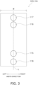
- Fig. 3 illustrates an inlet and an outlet for the refrigerant and an inlet and an outlet for the heat medium in one of the plates 103 and 104 of the heat exchanger 100.
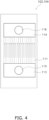
- Fig. 4 illustrates an image of the flow of the refrigerant in one of the plates 103 and 104 of the heat exchanger 100.
- Fig. 5 illustrates an image of the flow of the heat medium in one of the plates 103 and 104 of the heat exchanger 100.
- FIG. 5 schematically illustrate the plates 103 and 104 of the heat exchanger 100 and illustrate the inlets, the outlets, the flow paths, and so forth in an exaggerated manner. Portions that are not used for the description are not illustrated in Fig. 2 to Fig. 5 .
- the heat exchanger 100 causes the refrigerant and the heat medium to exchange heat with each other without becoming mixed together.
- the heat exchanger 100 of the present embodiment is the cascade heat exchanger 33 illustrated in Fig. 1 .
- the refrigerant of the present embodiment includes, for example, at least one of an HFC-based refrigerant and an HFO-based refrigerant
- the heat medium of the present embodiment includes, for example, carbon dioxide.
- the heat exchanger 100 is a plate(-type) heat exchanger that includes a plurality of plates 103 and 104 stacked one on top of the other.
- the number of the plates 103 and 104 is not limited and is appropriately set in accordance with the required performance.
- the heat exchanger 100 includes two frames 102, a plurality of plates 103 and 104, a refrigerant inlet pipe 105, a refrigerant outlet pipe 106, a heat-medium inlet pipe 107, and a heat-medium outlet pipe 108.
- the plurality of plates 103 and 104 are stacked on top of one another between the two frames 102.
- the plurality of plates 103 and 104 includes two types of heat transfer plates, which are the first plates 103 and the second plates 104.
- the first plates 103 and the second plates 104 are alternately stacked on top of one another.
- the frames 102 and the plates 103 and 104 are integrally joined together by brazing.
- the plates 103 and 104 are each formed of a metal flat plate. Peripheral edge portions of the adjacent plates 103 and 104 are in contact with each other, and the first flow paths 111 (see Fig. 4 ), which are the flow paths of the refrigerant, or the second flow paths 112 (see Fig. 5 ), which are the flow paths of the heat medium, are formed between the plates 103 and 104.
- the first flow paths 111 and the second flow paths 112 are alternately provided.
- the refrigerant that flows through the first flow paths 111 and the heat medium that flows through the second flow paths 112 are caused to exchange heat with each other via the plates 103 and 104.
- the refrigerant inlet pipe 105, the refrigerant outlet pipe 106, the heat-medium inlet pipe 107, and the heat-medium outlet pipe 108 are attached to the frame 102. In Fig. 2 , these pipes are arranged in the order of the heat-medium outlet pipe 108, the refrigerant inlet pipe 105, the refrigerant outlet pipe 106, and the heat-medium inlet pipe 107 from bottom to top.
- a first inlet 115, a first outlet 116, a second inlet 117, and a second outlet 118 are formed in each of the plates 103 and 104.
- the first inlets 115 serve as an inlet for the refrigerant that flows into the first flow paths 111.
- the first inlets 115 of the plurality of plates 103 and 104 form a refrigerant inflow space.
- the refrigerant inflow space communicates with the refrigerant inlet pipe 105.
- the refrigerant introduced from the refrigerant inlet pipe 105 flows into the first flow paths 111 through the first inlets 115.
- a gas-liquid two-phase refrigerant passes through the first inlets 115 during the cooling operation.
- the first outlets 116 serve as an outlet for the refrigerant flowing through the first flow paths 111.
- the first outlets 116 of the plurality of plates 103 and 104 form a refrigerant outflow space.
- the refrigerant outflow space communicates with the refrigerant outlet pipe 106.
- the refrigerant flowing through the first flow paths 111 flows into the refrigerant outlet pipe 106 through the first outlets 116.
- the gas-phase refrigerant passes through the first outlets 116 during the cooling operation.
- the second inlets 117 serve as an inlet for the heat medium that flows into the second flow paths 112.
- the second inlets 117 of the plurality of plates 103 and 104 form a heat-medium inflow space.
- the heat-medium inflow space communicates with the heat-medium inlet pipe 107.
- the heat medium introduced from the heat-medium inlet pipe 107 flows into the second flow paths 112 through the second inlets 117.
- the second outlets 118 serve as an outlet for the heat medium flowing through the second flow paths 112.
- the second outlets 118 of the plurality of plates 103 and 104 form a heat-medium outflow space.
- the heat-medium outflow space communicates with the heat-medium outlet pipe 108.
- the heat medium flowing through the second flow paths 112 flows into the heat-medium outlet pipe 108 through the second outlets 118.
- the refrigerant evaporates, and the heat medium condenses in the heat exchanger 100.
- the first inlets 115 serve as an inlet for a medium that evaporates, the medium being the refrigerant or the heat medium
- the first outlets 116 serve as an outlet for the medium that evaporates, the medium being the refrigerant or the heat medium.
- the second inlets 117 serve as an inlet for a medium that condenses, the medium being the refrigerant or the heat medium
- the second outlets 118 serve as an outlet for the medium that evaporates, the medium being the refrigerant or the heat medium.
- the term “condense” includes a change from a gas phase state to a liquid phase state and a change from a supercritical state to a liquid phase state.
- the refrigerant is on a low-pressure side
- the heat medium is on a high-pressure side in the heat exchanger 100.
- the first inlets 115 serve as an inlet for a medium on the low-pressure side, the medium being the refrigerant or the heat medium
- the first outlets 116 serve as an outlet for the medium on the low-pressure side, the medium being the refrigerant or the heat medium.
- the second inlets 117 serve as an inlet for a medium on the high-pressure side, the medium being the refrigerant or the heat medium
- the second outlets 118 serve as an outlet for the medium on the high-pressure side, the medium being the refrigerant or the heat medium.
- One or a plurality of through holes are formed as the first inlet 115 in each of the plates 103 and 104.
- one through hole is formed as the first inlet 115 in each of the plates 103 and 104.
- One or a plurality of through holes are formed as the first outlet 116 in each of the plates 103 and 104.
- one through hole is formed as the first outlet 116 in each of the plates 103 and 104.
- One or a plurality of through holes are formed as the second inlet 117 in each of the plates 103 and 104.
- one through hole is formed as the second inlet 117 in each of the plates 103 and 104.
- One or a plurality of through holes are formed as the second outlet 118 in each of the plates 103 and 104.
- one through hole is formed as the second outlet 118 in each of the plates 103 and 104.
- first inlets 115, the first outlets 116, the second inlets 117, and the second outlets 118 may have the same shape or may have different shapes from one another.
- first inlets 115, the first outlets 116, the second inlets 117, and the second outlets 118 are circular through holes having approximately the same size.
- the first inlets 115 and the first outlets 116 each have line symmetry with respect to a center line L in the width direction of the plates 103 and 104 (the transverse direction in Fig. 3 ).
- the distance between the center line L and the centroid of the first inlet 115 and the distance between the center line L and the centroid of the first outlet 116 when viewed in the stacking direction are each 10% or less of a width dimension W of each of the plates 103 and 104.
- the plurality of plates 103 and 104 each have a rectangular shape when viewed in their stacking direction.
- the corners of the rectangular shape may be defined by straight lines or may be defined by curved lines such as R-shaped lines.
- the longitudinal direction and the lateral direction of the plates 103 and 104 are specified, and their width direction is the same as the lateral direction.
- the center line L is defined by connecting the center in the width direction.
- each of the first inlets 115 has symmetry with respect to the center line L.
- Each of the first outlets 116 has line symmetry with respect to the center line L.
- the center of the first inlet 115 and the center of the first outlet 116 are located on the center line L.
- the centers of the first inlets 115 and the centers of the first outlets 116 of the present disclosure may each be shifted to, for example, the left side or the right side with respect to the center line L within a range of 10% or less of the width dimension W of each of the plates 103 and 104.
- the second inlets 117 and the second outlets 118 each have line symmetry with respect to the center line L in the width direction (the transverse direction in Fig. 3 ) of the plates 103 and 104.
- each of the second inlets 117 has line symmetry with respect to the center line L.
- Each of the second outlet 118 has line symmetry with respect to the center line L.
- the center of the second inlet 117 and the center of the second outlet 118 are located on the center line L.
- the centers of the second inlets 117 and the centers of the second outlets 118 of the present disclosure may each be shifted to, for example, the left side or the right side with respect to the center line L within a range of 10% or less of the width dimension W of each of the plates 103 and 104.
- the first inlet 115 and the first outlet 116 are positioned between the second inlet 117 and the second outlet 118. In other words, the first inlet 115 and the first outlet 116 are closer to the center in the longitudinal direction than the second inlet 117 and the second outlet 118.
- first inlet 115 is closer to the center in the longitudinal direction than the second inlet 117.
- the first outlet 116 is closer to the center in the longitudinal direction than the second outlet 118.
- first inlet 115, the first outlet 116, the second inlet 117, and the second outlet 118 are positioned on a single straight line in the longitudinal direction.
- first inlet 115, the first outlet 116, the second inlet 117, and the second outlet 118 are positioned on the center line L in the width direction of each of the plates 103 and 104.
- the first inlet 115 is formed below the first outlet 116.
- the second inlet 117 is formed above the second outlet 118. In Fig. 3 , they are formed in the order of the second outlet 118, the first inlet 115, the first outlet 116, and the second inlet 117 from bottom to top.
- the angle formed by a line connecting the first inlet 115 and the first outlet 116 to each other and a line connecting the second inlet 117 and the second outlet 118 to each other is less than 25 degrees.
- the line connecting the first inlet 115 and the first outlet 116 to each other is the center line L
- the line connecting the second inlet 117 and the second outlet 118 to each other is the center line L.
- the angle formed by the line connecting the first inlet 115 and the first outlet 116 to each other and the line connecting the second inlet 117 and the second outlet 118 to each other is zero degrees.
- Irregularities having a herringbone shape, a corrugated shape, or the like are formed on the front and rear surfaces of each of the plates 103 and 104.
- the first plates 103 and the second plates 104 are stacked on top of one another such that the front surface of one of the plates faces the rear surface of the other plate.
- the first flow paths 111 through which the refrigerant flows as illustrated in Fig. 4 are formed between the front surface of each of the first plates 103 and the rear side of the corresponding second plate 104.
- the refrigerant in a two phase state flows through the first flow paths 111.
- the refrigerant in a gas-liquid two-phase state flows through the first flow paths 111.
- the refrigerant in the gas-liquid two phase state flows through at least part of the first flow paths 111.
- the refrigerant in the gas-liquid two-phase state flows in the vicinity of the first inlet 115 of the first flow paths 111.
- the gas-phase refrigerant or the liquid-phase refrigerant flows through the rest of the first flow paths 111.
- the gas-phase refrigerant flows in the vicinity of the first outlet of the first flow paths 111.
- the second flow paths 112 through which the heat medium flows as illustrated in Fig. 5 are formed between the rear surface of each of the first plates 103 and the front surface of the corresponding second plate 104.
- the heat medium in a supercritical state flows through the second flow paths 112 during the cooling operation.
- the refrigerant flows from bottom to top, and the heat medium flows from top to bottom. Accordingly, the refrigerant and the heat medium form counterflows.
- a first inlet header 113 and a first outlet header 114 are formed between each of the plates 103 and the corresponding plate 104.
- the first inlet header 113 is formed between the first inlet 115 and the first flow paths 111.
- the first outlet header 114 is formed between the first outlet 116 and the first flow paths 111.
- the first inlet header 113 forms a header space for causing the refrigerant to flow into the first flow paths 111 in a split manner.
- the first inlet header 113 is provided on an upstream side of the first flow paths 111.
- the first outlet header 114 forms a header space for collecting the refrigerant that has flowed through the first flow paths 111.
- the first outlet header 114 is provided on a downstream side of the first flow paths 111.
- the first flow paths 111 are a plurality of flow paths extending in the longitudinal direction of the plates 103 and 104.
- the plurality of flow paths are spaced apart from one another.
- the plurality of flow paths forming the first flow paths 111 are separated from one another and do not join one another from the first inlet header 113 to the first outlet header 114.
- the plurality of flow paths may each have a meandering shape, in the present embodiment, the plurality of flow paths extend linearly so as to be parallel to one another.
- a second inlet header and a second outlet header are formed between each of the plates 103 and the corresponding plate 104.
- the second inlet header is formed between the second inlet 117 and the second flow paths 112.
- the second outlet header is formed between the second outlet 118 and the second flow paths 112.
- the second flow paths 112 are a plurality of flow paths (not illustrated) extending in the longitudinal direction of the plates 103 and 104.
- the plurality of flow paths are spaced apart from one another.
- the plurality of flow paths forming the second flow paths 112 are separated from one another and do not join one another from the second inlet 117 to the second outlet 118.
- the plurality of flow paths extend from the second inlet header to the second outlet header in such a manner as to avoid the first inlet 115 and the first outlet 116.
- a low-pressure refrigerant in a gas-liquid two-phase state introduced from the refrigerant inlet pipe 105 of the heat exchanger 100 passes through the first inlets 115 and flows into the first flow paths 111.
- This refrigerant in the two phase state flows through the first flow paths 111, evaporates by exchanging heat with the heat medium in the adjacent second flow paths 112, and cools the heat medium.
- the evaporated gas-phase refrigerant passes through the first outlets 116 and is discharged from the refrigerant outlet pipe 106.
- a high-pressure heat medium in a supercritical state introduced from the heat-medium inlet pipe 107 of the heat exchanger 100 passes through the second inlets 117 and flows into the second flow paths 112.
- This heat medium flows through the second flow paths 112, condenses by exchanging heat with the refrigerant in the adjacent first flow paths 111, and is cooled.
- the cooled liquid-phase heat medium passes through the second outlet 118 and is discharged from the heat-medium outlet pipe 108.
- a high-pressure gas-phase refrigerant introduced from the refrigerant inlet pipe 105 of the heat exchanger 100 passes through the first inlets 115 and flows into the first flow paths 111.
- This gas-phase refrigerant flows through the first flow paths 111, condenses by exchanging heat with the heat medium in the adjacent second flow paths 11, and heats the heat medium.
- the condensed liquid-phase refrigerant passes through the first outlets 116 and is discharged from the refrigerant outlet pipe 106.
- a low-pressure heat medium in a gas-liquid two-phase state introduced from the heat-medium inlet pipe 107 of the heat exchanger 100 passes through the second inlets 117 and flows into the second flow paths 112.
- This heat medium flows through the second flow paths 112, evaporates by exchanging heat with the refrigerant in the adjacent first flow paths 111, and is heated.
- the heated gas-phase heat medium passes through the second outlets 118 and is discharged from the heat-medium outlet pipe 108.
- the heat exchanger 100 includes the plurality of plates 103 and 104 stacked on top of one another.
- the heat exchanger 100 causes the refrigerant and the heat medium to exchange heat with each other.
- the first flow path 111 and the second flow path 112 are formed between the plates 103 and 104.
- the refrigerant in the two phase state flows through the first flow paths 111.
- the heat medium flows through the second flow paths 112.
- the first inlet 115 and the first outlet 116 are formed in each of the plates 103 and 104.
- the first inlet 115 serves as the inlet for the refrigerant that flows through the first flow path 111.
- the first outlet 116 serves as the outlet for the refrigerant flowing through the first flow path 111.
- the first inlet 115 and the first outlet 116 each have line symmetry with respect to the center line L in the width direction of each of the plates 103 and 104.
- the first inlet 115 serving as the inlet for the refrigerant in the two phase state and the first outlet 116 serving as the outlet for the refrigerant are each formed at a position where it has line symmetry with respect to the center line L in the width direction of each of the plates 103 and 104. This can reduce the difference in flow path resistance due to the positional relationship between the first inlet 115 and the first outlet 116.
- the amount of the refrigerant flowing through the first flow path 111 can be made more uniform. Therefore, uneven flow of the refrigerant can be suppressed, and thus, the heat exchange between the refrigerant and the heat medium can be facilitated, so that the performance of the heat exchanger 100 can be improved.
- the first inlet header 113 and the first outlet header 114 be formed between the plates 103 and 104.
- the first inlet header 113 is formed between the first inlet 115 and the first flow path 111.
- the first outlet header 114 is formed between the first outlet 116 and the first flow path 111.
- the refrigerant can be collected in the first inlet header 113 from the first inlet 115 and caused to flow into the first flow path 111 in a split manner from the first inlet header 113. Then, the refrigerant can be collected from the first flow path 111 into the first outlet header 114.
- the first flow path 111 be a plurality of flow paths extending in the longitudinal direction of each of the plates 103 and 104.
- the plurality of flow paths are spaced apart from one another.
- the first inlet 115 serving as the inlet for the refrigerant in the two phase state and the first outlet 116 serving as the outlet for the refrigerant are each formed at a position where it has line symmetry with respect to the center line L in the width direction of each of the plates 103 and 104.
- each of the plates 103 and 104 further has the second inlet 117 and the second outlet 118 formed therein.
- the second inlet 117 serves as the inlet for the heat medium that flows through the second flow path 112.
- the second outlet 118 serve as the outlet for the heat medium flowing through the second flow path 112.
- the angle formed by the line connecting the first inlet 115 and the first outlet 116 to each other and the line connecting the second inlets 117 and the second outlet 118 to each other is less than 25 degrees.
- the inventor of the present invention has found that, in each of the plates 103 and 104, when the angle formed by the line connecting the first inlet 115 for the refrigerant and the first outlet 116 for the refrigerant to each other and the line connecting the second inlet 117 for the heat medium and the second outlet 118 for the heat medium to each other is 25 degrees or more, a portion where heat exchange is not facilitated occurs locally. Therefore, when the angle formed by the line connecting the first inlet 115 for the refrigerant and the first outlet 116 for the refrigerant to each other and the line connecting the second inlet 117 for the heat medium and the second outlet 118 for the heat medium to each other is less than 25 degrees, uneven flow of the refrigerant can be effectively suppressed.
- the second inlet 117 and the second outlet 118 each have line symmetry with respect to the center line L in the width direction of each of the plates 103 and 104.
- the difference in flow path resistance due to the positional relationship between the second inlets 117 and the second outlets 118 can be reduced.
- the amount of the heat medium flowing through the second flow path 112 can be made more uniform.
- uneven flow of the heat medium can be further suppressed, and thus, the heat exchange between the refrigerant and the heat medium can be further facilitated, so that the performance of the heat exchanger 100 can be further improved.
- the first inlet 115 and the first outlet 116 be located between the second inlet 117 and the second outlet 118 in the longitudinal direction of each of the plates 103 and 104.
- the first inlet 115 and the first outlet 116 of the first flow path 111 are positioned closer to the center than the second inlet 117 and the second outlet 118 of the second flow path 112, in which uneven flow is less likely to occur.
- the influence of the second inlet 117 and the second outlet 118 on the refrigerant flowing through the first flow paths 111 can be reduced. Therefore, uneven flow of the refrigerant flowing through the first flow path 111 can be suppressed.
- the inlet (the first inlet 115 in the present embodiment) and the outlet (the first outlet 116 in the present embodiment) on the low-pressure side for the refrigerant and the heat medium are located between the inlet (the second inlet 117 in the present embodiment) and the outlet (the second outlet 118 in the present embodiment) on the high-pressure side for the refrigerant and the heat medium.
- the flow path (the first flow path 111 in the present embodiment) through which the medium on the low-pressure side, the medium being the refrigerant or the heat medium (the refrigerant in the present embodiment), flows is susceptible to the influence of pressure loss.
- the inlet and the outlet for the medium on the low-pressure side that are more affected by pressure loss are positioned closer to the center than the inlet and the outlet for the medium on the high-pressure side (the heat medium in the present embodiment) with lower pressure loss.
- the first inlet 115 is formed below the first outlet 116.
- the plates 103 and 104 in which the first inlets 115 and the first outlets 116 are formed in this manner such that the refrigerant flows from bottom to top can also be used.
- the second inlets 117 and the second outlets 118 each have line symmetry with respect to the center line L in the width direction of the plates 103 and 104.
- the present disclosure is not limited to this.
- the present modification as illustrated in Fig. 6 , when viewed in the stacking direction of each of the plates 103 and 104, neither the second inlet 117 nor the second outlet 118 has line symmetry with respect to the center line L.
- Fig. 6 illustrates the inlet and the outlet for the refrigerant and the inlet and the outlet for the heat medium in one of the plates 103 and 104 of a heat exchanger according to the present modification.
- the first inlet 115 and the first outlet 116 each have line symmetry with respect to the center line L.
- the position of the first inlet 115 of the present modification is lower than that in the embodiment, and the position of the first outlet 116 of the present modification is higher than that in the embodiment.
- the second inlet 117 is formed on one side (the left side in Fig. 6 ) in the width direction with respect to the center line L.
- the second outlet 118 is formed on the other side (the right side in Fig. 6 ) in the width direction with respect to the center line L.
- the second inlet 117 and the second outlet 118 are point-symmetric with respect to a center O of each of the plates 103 and 104.
- the first inlet 115 and the second outlet 118 are located at the same position in the longitudinal direction (the vertical direction in Fig. 6 ).
- the first outlet 116 and the second inlet 117 are located at the same position in the longitudinal direction.
- An angle ⁇ formed by a line (here, the center line L) connecting the first inlet 115 and the first outlet 116 to each other and a line L1 connecting the second inlet 117 and the second outlet 118 to each other is more than 0 degrees and less than 25 degrees.
- Fig. 7 illustrates an image of the flow of the refrigerant in one of the plates 103 and 104 of the heat exchanger according to the present modification.
- the refrigerant flows from bottom to top as in the embodiment.
- the first flow paths 111 are a plurality of flow paths that extend in the longitudinal direction of the plates 103 and 104 and that are spaced apart from one another.
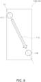
- Fig. 8 illustrates an image of the flow of the heat medium in one of the plates 103 and 104 of the heat exchanger according to the present modification.
- the second flow paths 112 flow from the upper left to the lower right.
- the second flow paths 112 are a plurality of flow paths that extend in a direction crossing the longitudinal direction of the plates 103 and 104 at an angle of less than 25 degrees and that are spaced apart from one another.
- the heat exchanger of the present modification is suitably used for a cascade heat exchanger of a refrigerant cycle system dedicated to cooling.
- a refrigerant in a two phase state flows through the first flow paths 111.
- the first inlets 115 and the first outlets 116 each have line symmetry with respect to the center line L.
- uneven flow of the refrigerant in the two phase state that flows into the first flow paths 111 through the first inlets 115 can be suppressed.
- the heat medium that flows into the second flow paths 112 through the second inlets 117 is in a gas phase state.
- the heat medium does not become a two phase state in the second flow paths 112, so that the heat medium is less likely to flow unevenly compared with the refrigerant.
- the influence of the second inlets 117 and the second outlets 118 each not having line symmetry with respect to the center line L is small.
- the heat exchanger of the present modification can also be used for a cascade heat exchanger that performs a cooling operation and a heating operation.
- a refrigerant in a two phase state flows through the first flow paths 111 that are formed between the first inlets 115 and the first outlets 116 each having line symmetry with respect to the center line L.
- a single through hole is formed as each of the first inlet 115, the first outlet 116, the second inlet 117, and the second outlet 118.
- the present disclosure is not limited this.
- a single through hole is formed as the first inlet 115 and the second inlet, and a plurality of through holes are formed as the first outlet 116 and the second outlet 118. Note that Fig.
- FIG. 9 illustrates the inlet for the refrigerant, the outlet for the refrigerant, the inlet for the heat medium, the outlet for the heat medium, an image of the flow of the refrigerant, and an image of the flow of the heat medium in one of the plates 103 and 104 of the heat exchanger according to the present modification.
- the first inlet 115 is located on the center line L as in the embodiment.
- the first outlet 116 is constituted by two through holes 116a and 116b.
- the two through holes 116a and 116b are arranged so as to be line-symmetrical to each other with respect to the center line L.
- the centroids of the two through holes 116a and 116b are located on the center line L.
- the middle point of a line connecting the centers of the two through holes 116a and 116b is located on the center line L.
- the two through holes 116a and 116b have the same shape and the same size.
- At least one of the two through holes 116a and 116b may be shifted to, for example, the left side or the right side as long as the distance between the centroid of each of the two through holes 116a and 116b and the center line L is 10% or less of the width dimension W of each of the plates 103 and 104, and for example, the two through holes 116a and 116b may have different sizes and different shapes.
- the second inlet 117 is located on the center line L as in the embodiment.
- the second outlet 118 is constituted by two through holes 118a and 118b.
- the two through holes 118a and 118b are arranged so as to be line-symmetrical to each other with respect to the center line L.
- the centroids of the two through holes 118a and 118b are located on the center line L.
- the middle point of a line connecting the centers of the two through holes 118a and 118b is located on the center line L.
- the two through holes 118a and 118b have the same shape and the same size.
- At least one of the two through holes 118a and 118b may be shifted to, for example, the left side or the right side as long as the distance between the centroid of each of the two through holes 118a and 118b and the center line L is 10% or less of the width dimension W of each of the plates 103 and 104, and for example, the two through holes 118a and 118b may have different sizes and different shapes.
- the line connecting the first inlet 115 and the first outlet 116 to each other and the line connecting the second inlet 117 and the second outlet 118 to each other in the embodiment are lines connecting their centroids. More specifically, the line connecting the first inlet 115 and the first outlet 116 is a line connecting the first inlet 115 and the centroids of the two through holes 116a and 116b, and thus, in this case, it coincides with the center line L.
- the line connecting the second inlet 117 and the second outlet 118 is a line connecting the second inlet 117 and the centroids of the two through holes 118a and 118b, and thus, in this case, it coincides with the center line L.
- the angle formed by the line connecting the first inlet 115 and the first outlet 116 to each other and the line connecting the second inlet 117 and the second outlet 118 to each other is zero degrees as in the embodiment.
- the first inlet 115 is located above the second outlet 118.
- the first outlet 116 is located above the second inlet 117.
- the first flow paths 111 are formed such that the refrigerant flows from the first inlet 115 toward the through holes 116a and 116b, which are the two first outlets 116.
- the second flow paths 112 are formed such that the heating media flows from the second inlet 117 toward the through holes 118a and the 118b, which are the two second outlets 118.
- the length of each of the first flow paths 111 is approximately the same as the length of each of the second flow paths 112.
- a plurality of through holes are formed as the first inlets 115.
- the plurality of plates 103 and 104 in each of which a single through hole is formed as the first inlet 115 in this manner can be used.
- the refrigerant inlet pipe 105 which is attached to the frames 102, and the first inlets 115 of the plates 103 and 104 are at the same position in the vertical direction and the transverse direction.
- the refrigerant outlet pipe 106 which is attached to the frames 102, and the first outlets 116 of the plates 103 and 104 are at the same position in the vertical direction and the transverse direction.
- the heat-medium inlet pipe 107 which is attached to the frames 102, and the second inlets 117 of the plates 103 and 104 are at the same position in the vertical direction and the transverse direction.
- the heat-medium outlet pipe 108 which is attached to the frames 102, and the second outlets 118 of the plates 103 and 104 are at the same position in the vertical direction and the transverse direction.
- the present disclosure is not limited to this.
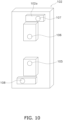
- Fig. 10 illustrates a frame according to the present modification.
- protruding portions 102a are formed on the frame 102.
- the protruding portions 102a are each a protrusion formed on a portion of a surface of the frame 102, the surface being opposite to a surface of the frame 102 facing the plates 103 and 104.
- the protruding portions 102a are formed by, for example, press working.
- the refrigerant inlet pipe 105, the refrigerant outlet pipe 106, the heating-medium inlet pipe 107, and the heating-medium outlet pipe 108 are attached to the protruding portions 102a.
- the refrigerant inlet pipe 105, the refrigerant outlet pipe 106, the heat-medium inlet pipe 107, and the heat medium outlet pipe 108 are not arranged in line with respect to a center line in a width direction of the frame 102.
- the degree of difficulty in a process of connecting the refrigerant inlet pipe 105, the refrigerant outlet pipe 106, the heat-medium inlet pipe 107, and the heat-medium outlet pipe 108 to the frame 102 can be reduced.
- R32 is mentioned as an example of the refrigerant
- carbon dioxide is mentioned as an example of the heat medium.
- the present disclosure is not limited to this.
- an HFO-based refrigerant, a mixed refrigerant of R32 and an HFO-based refrigerant, carbon dioxide, ammonia, propane, or the like can be used.
- the heat medium for example, R32, an HFO-based refrigerant, a mixed refrigerant of R32 and an HFO-based refrigerant, refrigerants such as carbon dioxide, ammonia, and propane, water, an antifreeze liquid, and the like can be used.
- HFO-based refrigerant for example, HFO-1234yf, HFO-1234ze, or the like can be used.
- the same refrigerant is used as the refrigerant, and alternatively, different media may be used.
- the heat medium it is preferable that the heat medium have at least one of a lower global warming potential (GWP), a lower ozone depletion potential (ODP), lower combustibility, and lower toxicity than the refrigerant.
- GWP global warming potential
- ODP ozone depletion potential
- the refrigerant flowing through the first flow paths 111 and the heat medium flowing through the second flow paths 112 form counterflows, they may form parallel flows.
- the heat exchanger 100 is applied to a cascade heat exchanger, the present disclosure is not limited this.
- the heat exchanger of the present disclosure can be applied to all heat exchangers used in refrigerant cycle systems.
Landscapes
- Engineering & Computer Science (AREA)
- Physics & Mathematics (AREA)
- Thermal Sciences (AREA)
- Mechanical Engineering (AREA)
- General Engineering & Computer Science (AREA)
- Heat-Exchange Devices With Radiators And Conduit Assemblies (AREA)
Abstract
Description
- The present disclosure relates to a heat exchanger.
- In the related art, a plate-type heat exchanger formed by stacking a plurality of plates on top of one another is known. An example of such a plate-type heat exchanger is disclosed in
Japanese Unexamined Patent Application Publication No. 11-173772 - In the plate-type heat exchanger disclosed in
PTL 1, a third opening for guiding water introduced from a water inlet pipe to a water flow path is provided at a lower end of a heat transfer plate, and a fourth opening for guiding the water in the water flow path to a water outlet pipe is provided at an upper end of the heat transfer plate. The third opening and the fourth opening are provided at a central portion of the heat transfer plate in a width direction of the heat transfer plate. - In
PTL 1 mentioned above, a first opening for guiding a refrigerant introduced from a refrigerant inlet pipe to a refrigerant flow path is provided at the lower end of the heat transfer plate, and a second opening for guiding the refrigerant in the refrigerant flow path to a refrigerant outlet pipe is provided at the upper end of the heat transfer plate. However, while the first opening is provided at the center portion of the heat transfer plate in the width direction, the second opening is provided at an end portion of the heat transfer plate in the width direction. Accordingly, the refrigerant may sometimes concentrate at the end portion where the second opening is provided. In this case, the amount of refrigerant in each refrigerant flow path becomes uneven, and thus, the performance deteriorates. - A heat exchanger according to a first aspect includes a plurality of plates stacked on top of one another. The heat exchanger causes a refrigerant and a heat medium to exchange heat with each other. A first flow path and a second flow path are formed between the plates. The refrigerant in a two phase state flows through the first flow path. The heat medium flows through the second flow path. The plate has a first inlet and a first outlet. The first inlet serves as an inlet for the refrigerant that flows into the first flow path. The first outlet serves as an outlet for the refrigerant that flows into the first flow path. When viewed in a direction in which the plates are stacked on top of one another, the first inlet and the first outlet have line symmetry with respect to a center line in a width direction of the plate.
- According to the heat exchanger of the first aspect, when viewed in the stacking direction of the plates, the first inlet serving as the inlet for the refrigerant in the two phase state and the first outlet serving as the outlet for the refrigerant are each formed at a position where it has line symmetry with respect to the center line in the width direction of the plate. This can reduce the difference in flow path resistance due to the positional relationship between the first inlet and the first outlet. Thus, when the refrigerant that flows through the first flow path between the first inlet and the first outlet flows into the first flow path through the first inlet while it is in the two phase state, the amount of the refrigerant flowing through the first flow path can be made more uniform. Therefore, uneven flow of the refrigerant can be suppressed, so that the performance of the heat exchange can be improved.
- A heat exchanger according to a second aspect is the heat exchanger of the first aspect, and one of the plates has a single or a plurality of through holes serving as the first inlet.
- As in the heat exchanger of the second aspect, the plurality of plates in which a single or a plurality of through holes are formed as the first inlets can be used.
- A heat exchanger according to a third aspect is the heat exchanger of the first aspect or the second aspect, and a first inlet header and a first outlet header are formed between the plates. The first inlet header is formed between the first inlet and the first flow path. The first outlet header is formed between the first outlet and the first flow path.
- In the heat exchanger according to the third aspect, the refrigerant can be collected in the first inlet header from the first inlet and caused to flow into the first flow path in a split manner from the first inlet header. In addition, the refrigerant can be collected from the first flow path into the first outlet header.
- A heat exchanger according to a fourth aspect is the heat exchanger of the third aspect, and the first flow path includes a plurality of flow paths extending in a longitudinal direction of the plate. The plurality of flow paths are spaced apart from each other.
- As in the heat exchanger according to the fourth aspect, uneven flow of the refrigerant is more likely to occur in the plurality of flow paths, which serve as the first flow path, which extend in the longitudinal direction, and which are spaced apart from each other. Here, when viewed in the stacking direction of the plates, the first inlet serving as the inlet for the refrigerant in the two phase state and the first outlet serving as the outlet for the refrigerant are each formed at a position where it has line symmetry with respect to the center line in the width direction of the plate. Thus, even when the first flow path has a shape in which uneven flow of the refrigerant is likely to occur, the uneven flow can be suppressed.
- A heat exchanger according to a fifth aspect is the heat exchanger according to any one of the first aspect to the fourth aspect, and the plate further has a second inlet and a second outlet. The second inlet serves as an inlet for the heat medium that flows into the second flow path. The second outlet serves as an outlet for the heat medium that flows into the second flow path. An angle formed by a line connecting the first inlet and the first outlet to each other and a line connecting the second inlet and the second outlet to each other is less than 25 degrees.
- As in the heat exchanger according to the fifth aspect, when the angle formed by the line connecting the first inlet for the refrigerant and the first outlet for the refrigerant to each other and the line connecting the second inlet for the heat medium and the second outlet for the heat medium to each other is less than 25 degrees, uneven flow of the refrigerant can be effectively suppressed.
- A heat exchanger according to a sixth aspect is the heat exchanger according to any one of the first aspect to the fifth aspect, and the plate further has a second inlet and a second outlet. The second inlet serves as an inlet for the heat medium that flows into the second flow path. The second outlet serves as an outlet for the heat medium that flows into the second flow path. When viewed in the stacking direction of the plates, the second inlet and the second outlet have line symmetry with respect to a center line in a width direction of the plates.
- According to the heat exchanger of the sixth aspect, the difference in flow path resistance due to the positional relationship between the second inlet and the second outlet can be reduced. Thus, the amount of the heat medium flowing through the second flow path can be made more uniform. Therefore, uneven flow of the heat medium can be further suppressed, so that the performance of the heat exchange can be further improved.
- A heat exchanger according to a seventh aspect is the heat exchanger according to any one of the first aspect to the sixth aspect, and the plate further has a second inlet and a second outlet. The second inlet serves as an inlet for the heat medium that flows into the second flow path. The second outlet serves as an outlet for the heat medium that flows into the second flow path. In the longitudinal direction of the plate, the first inlet and the first outlet are positioned between the second inlet and the second outlet.
- In the first flow path through which the refrigerant in the two phase state flows, uneven flow is more likely to occur than in the second flow path through which the heat medium flows. Accordingly, here, the first inlet and the first outlet of the first flow path, in which uneven flow is likely to occur, are positioned closer to the center than the second inlet and the second outlet of the second flow path, in which uneven flow is less likely to occur. As a result, the influence of the second inlet and the second outlet on the refrigerant flowing through the first flow path can be reduced.
- A heat exchanger according to an eighth aspect is the heat exchanger according to any one of the first aspect to the seventh aspect, and the plate further has a second inlet and a second outlet. The second inlet serves as an inlet for the heat medium that flows into the second flow path. The second outlet serves as an outlet for the heat medium that flows into the second flow path. In the longitudinal direction of the plate, a low-pressure-side inlet and a low-pressure-side outlet for the refrigerant and the heat medium are located between a high-pressure-side inlet and a high-pressure-side outlet for the refrigerant and the heat medium.
- The flow path through which a medium on the low-pressure side, the medium being the refrigerant or the heat medium, flows is susceptible to the influence of pressure loss. Thus, here, the inlet and the outlet for the medium on the low-pressure side that are more affected by pressure loss are positioned closer to the center than the inlet and the outlet for the medium on the high-pressure side with lower pressure loss. This can shorten the flow path of the medium on the low-pressure side, so that the influence of pressure loss can be reduced.
- A heat exchanger according to a ninth aspect is the heat exchanger according to any one of the first aspect to the eighth aspect, and the first inlet is formed below the first outlet.
- As in the heat exchanger according to the ninth aspect, the plate in which the first inlet and the first outlet are formed such that the refrigerant flows from bottom to top can also be used.
-
-
Fig. 1 is a schematic diagram illustrating a configuration of a refrigerant cycle system including a heat exchanger according to an embodiment. -
Fig. 2 is an exploded perspective view illustrating the heat exchanger according to the embodiment. -
Fig. 3 is a schematic diagram illustrating a plate of the heat exchanger according to the embodiment. -
Fig. 4 is a schematic diagram illustrating a flow of a refrigerant in the plate of the heat exchanger according to the embodiment. -
Fig. 5 is a schematic diagram illustrating a flow of a heat medium in the plate of the heat exchanger according to the embodiment. -
Fig. 6 is a perspective view illustrating a plate of a heat exchanger according to a modification. -
Fig. 7 is a schematic diagram illustrating a flow of a refrigerant in the plate of the heat exchanger according to the modification. -
Fig. 8 is a schematic diagram illustrating a flow of a heat medium in the plate of the heat exchanger according to the modification. -
Fig. 9 is a schematic diagram illustrating a plate of a heat exchanger according to another modification. -
Fig. 10 is a perspective view illustrating a frame according to another modification. - A refrigerant cycle system including a heat exchanger according to an embodiment of the present disclosure will be described with reference to
Fig. 1 . Note thatFig. 1 illustrates arefrigerant cycle system 1 that includes aheat exchanger 100 of the present embodiment. As illustrated inFig. 1 , therefrigerant cycle system 1 is an apparatus used for cooling and heating an interior of a building or the like by performing a vapor compression refrigeration cycle operation. - The
refrigerant cycle system 1 includes onefirst unit 10, onecascade unit 30, and onesecond unit 50. Thefirst unit 10 and thecascade unit 30 are connected by twofirst communication pipes 61. Thecascade unit 30 and thesecond unit 50 are connected by twosecond communication pipes 62. - A vapor-compression primary-
side cycle 20 is configured by connecting thefirst unit 10 and thecascade unit 30 to each other. The primary-side cycle 20 is a circuit for circulating a refrigerant. The refrigerant includes, for example, at least one of an HFC-based refrigerant, such as R32 or R410A, and an HFO-based refrigerant. Here, for example, R32 is used as the refrigerant that flows through the primary-side cycle 20. - A vapor compression secondary-
side cycle 40 is configured by connecting thecascade unit 30 and thesecond unit 50 to each other. The secondary-side cycle 40 is a circuit for circulating a heat medium. In some embodiments, the heat medium is water or the like, and alternatively, the heat medium may be a refrigerant. Here, for example, a carbon dioxide refrigerant is used as the heat medium that flows through the secondary-side cycle 40. - The
first unit 10 is a heat source unit. Thefirst unit 10 includes a first compressor 11, a first four-way switching valve 12, afirst heat exchanger 13, afirst expansion valve 14, a first liquid shut-offvalve 18, and a first gas shut-offvalve 19. - The first compressor 11 sucks in a low-pressure gas refrigerant serving as the refrigerant that circulates in the primary-
side cycle 20, compresses the low-pressure gas refrigerant, and discharges a high-pressure gas refrigerant. The first four-way switching valve 12 performs connection indicated by solid lines inFig. 1 in a cooling operation and performs connection indicated by dashed lines inFig. 1 in a heating operation. Thefirst heat exchanger 13 exchanges heat between the refrigerant and the outside air. Thefirst heat exchanger 13 functions as a condenser in the cooling operation and functions as an evaporator in the heating operation. Thefirst expansion valve 14 adjusts the flow rate of the refrigerant. In addition, thefirst expansion valve 14 functions as a decompression device that decompresses the refrigerant. - The first liquid shut-off
valve 18 and the first gas shut-offvalve 19 shut off a flow path through which the refrigerant circulates in the case of, for example, installation work of thefirst unit 10. - The
cascade unit 30 is used for exchanging heat between the refrigerant and the heat medium. Thecascade unit 30 includes asecond compressor 31, a second four-way switching valve 32, a cascade heat exchanger 33, a primary-side expansion valve 34, a secondary-side expansion valve 35, a second liquid shut-offvalve 38, and a second gas shut-offvalve 39. - The
second compressor 31 sucks in a low-pressure gas refrigerant serving as the heat medium that circulates in the secondary-side cycle 40, compresses the low-pressure gas refrigerant, and discharges a high-pressure refrigerant in a supercritical state. The second four-way switching valve 32 functions as a switching device. The second four-way switching valve 32 performs connection indicated by solid lines inFig. 1 in the cooling operation and performs connection indicated by dashed lines inFig. 1 in heating operation. - The cascade heat exchanger 33 exchanges heat between the refrigerant and the heat medium. As illustrated in
Fig. 2 , the cascade heat exchanger 33 is a plate-type heat exchanger 100. The cascade heat exchanger 33 includesfirst flow paths 111 through which the refrigerant flows andsecond flow paths 112 through which the heat medium flows. Thefirst flow paths 111 allow the refrigerant to pass therethrough. Thesecond flow paths 112 allow the heat medium to pass therethrough. In the cooling operation, the cascade heat exchanger 33 functions as an evaporator of the refrigerant and a condenser of the heat medium. In the heating operation, the cascade heat exchanger 33 functions as an evaporator of the refrigerant and a condenser of the heat medium. - The primary-side expansion valve 34 adjusts the amount of the refrigerant that circulates in the primary-
side cycle 20. In addition, the primary-side expansion valve 34 decompresses the refrigerant. - The secondary-
side expansion valve 35 adjusts the amount of the heat medium that circulates in the secondary-side cycle 40. In addition, the secondary-side expansion valve 35 decompresses the refrigerant. - The second liquid shut-off
valve 38 and the secondgas shutoff valve 39 shut off a flow path through which the heat medium circulates in the case of, for example, installation work of thecascade unit 30. - The
second unit 50 is a utilization unit. Thesecond unit 50 includes asecond heat exchanger 51 and asecond expansion valve 52. Thesecond heat exchanger 51 exchanges heat between the heat medium and indoor air. Thesecond heat exchanger 51 is, for example, a microchannel heat exchanger and includes a flat multi-hole pipe. Thesecond expansion valve 52 adjusts the amount of the heat medium that circulates in the secondary-side cycle 40. In addition, thesecond expansion valve 52 functions as a decompression device that decompresses the heat medium. - The first compressor 11 sucks in the low-pressure gas refrigerant and discharges the high-pressure gas refrigerant. The high-pressure gas refrigerant reaches the
first heat exchanger 13 via the first four-way switching valve 12. Thefirst heat exchanger 13 condenses the high-pressure gas refrigerant so as to generate a high-pressure liquid refrigerant. In this case, the refrigerant releases its heat to the outside air. The high-pressure liquid refrigerant passes through thefirst expansion valve 14 that is fully opened, and the high-pressure liquid refrigerant further passes through the first liquid shut-offvalve 18 and thefirst communication pipe 61 and reaches the primary-side expansion valve 34. The primary-side expansion valve 34 whose opening degree is appropriately set decompresses the high-pressure liquid refrigerant so as to generate a low-pressure gas-liquid two-phase refrigerant. The low-pressure gas-liquid two-phase refrigerant flows into thefirst flow paths 111 of the cascade heat exchanger 33. The cascade heat exchanger 33 evaporates the low-pressure gas-liquid two-phase refrigerant so as to generate a low-pressure gas refrigerant. In this case, the refrigerant in the primary-side cycle 20 absorbs heat from the heat medium in the secondary-side cycle 40. The low-pressure gas refrigerant flows out of thefirst flow paths 111, passes through thefirst communication pipe 61 and the first gas shut-offvalve 19, and is sucked into the first compressor 11 via the first four-way switching valve 12. - The
second compressor 31 sucks in the low-pressure gas refrigerant, which serves as the heat medium, and discharges the high-pressure refrigerant in the supercritical state. The high-pressure refrigerant flows into thesecond flow paths 112 of the cascade heat exchanger 33 via the second four-way switching valve 32. The cascade heat exchanger 33 condenses the high-pressure refrigerant by dissipating the heat of the high-pressure refrigerant so as to generate a high-pressure liquid refrigerant. In this case, the heat medium in the secondary-side cycle 40 releases its heat to the refrigerant in the primary-side cycle 20. The high-pressure liquid refrigerant flows out of thesecond flow paths 112 and reaches the secondary-side expansion valve 35. The secondary-side expansion valve 35 whose opening degree is appropriately set decompresses the high-pressure liquid refrigerant so as to generate a low-pressure gas-liquid two-phase refrigerant. The low-pressure gas-liquid two-phase refrigerant passes through the second liquid shut-offvalve 38 and thesecond communication pipe 62 and reaches thesecond expansion valve 52. Thesecond expansion valve 52 whose opening degree is appropriately set further reduces the pressure of the low-pressure gas-liquid two-phase refrigerant. The low-pressure gas-liquid two-phase refrigerant reaches thesecond heat exchanger 51. Thesecond heat exchanger 51 evaporates the low-pressure gas-liquid two-phase refrigerant so as to generate a low-pressure gas refrigerant. In this case, the refrigerant serving as the heat medium absorbs heat from the indoor air. The low-pressure gas refrigerant flows out of thesecond heat exchanger 51, passes through thesecond communication pipe 62 and the second gas shut-offvalve 39, and is sucked into thesecond compressor 31 via the second four-way switching valve 32. - The first compressor 11 sucks in the low-pressure gas refrigerant and discharges the high-pressure gas refrigerant. The high-pressure gas refrigerant passes through the first gas shut-off
valve 19 and thefirst communication pipe 61 via the first four-way switching valve 12 and flows into thefirst flow paths 111 of the cascade heat exchanger 33. The cascade heat exchanger 33 condenses the high-pressure gas refrigerant so as to generate the high-pressure liquid refrigerant. In this case, the refrigerant in the primary-side cycle 20 releases its heat to the heat medium in the secondary-side cycle 40. The high-pressure liquid refrigerant passes through the primary-side expansion valve 34 that is fully opened, and then, the high-pressure liquid refrigerant passes through thefirst communication pipe 61 and the first liquid shut-offvalve 18 and reaches thefirst expansion valve 14. Thefirst expansion valve 14 whose opening degree is appropriately set decompresses the high-pressure liquid refrigerant so as to generate a low-pressure gas-liquid two-phase refrigerant. The low-pressure gas-liquid two-phase refrigerant reaches thefirst heat exchanger 13. Thefirst heat exchanger 13 evaporates the low-pressure gas-liquid two-phase refrigerant so as to generate a low-pressure gas refrigerant. In this case, the refrigerant absorbs heat from the outside air. The low-pressure gas refrigerant passes through the first four-way switching valve 12 and is sucked into the first compressor 11. - The
second compressor 31 sucks in the low-pressure gas refrigerant, which serves as the heat medium, and discharges the high-pressure refrigerant in the supercritical state. The high-pressure refrigerant passes through the second gas shut-offvalve 39 and thesecond communication pipe 62 via the second four-way switching valve 32 and reaches thesecond heat exchanger 51. Thesecond heat exchanger 51 condenses the high-pressure refrigerant by dissipating the heat of the high-pressure refrigerant so as to generate a high-pressure liquid refrigerant. In this case, the refrigerant serving as the heat medium releases its heat to the indoor air. After that, the high-pressure liquid refrigerant reaches thesecond expansion valve 52. Thesecond expansion valve 52 whose opening degree is appropriately set decompresses the high-pressure liquid refrigerant so as to generate a low-pressure gas-liquid two-phase refrigerant. The low-pressure gas-liquid two-phase refrigerant passes through thesecond communication pipe 62 and the second liquid shut-offvalve 38 and reaches the secondary-side expansion valve 35. The secondary-side expansion valve 35 whose opening degree is appropriately set further reduces the pressure of the low-pressure gas-liquid two-phase refrigerant. The low-pressure gas-liquid two-phase refrigerant flows into thesecond flow paths 112 of the cascade heat exchanger 33. The cascade heat exchanger 33 evaporates the low-pressure gas-liquid two-phase refrigerant so as to generate the low-pressure gas refrigerant. In this case, the heat medium in the secondary-side cycle 40 absorbs heat from the refrigerant in the primary-side cycle 20. The low-pressure gas refrigerant flows out of thesecond flow paths 112, passes through the second four-way switching valve 32, and is sucked into thesecond compressor 31. - The
heat exchanger 100 according to an embodiment of the present disclosure will be described with reference toFig. 1 to Fig. 5 . Note thatFig. 2 illustrates an exploded state of theheat exchanger 100 and does not illustrate portions ofplates Fig. 3 illustrates an inlet and an outlet for the refrigerant and an inlet and an outlet for the heat medium in one of theplates heat exchanger 100.Fig. 4 illustrates an image of the flow of the refrigerant in one of theplates heat exchanger 100.Fig. 5 illustrates an image of the flow of the heat medium in one of theplates heat exchanger 100.Fig. 2 to Fig. 5 schematically illustrate theplates heat exchanger 100 and illustrate the inlets, the outlets, the flow paths, and so forth in an exaggerated manner. Portions that are not used for the description are not illustrated inFig. 2 to Fig. 5 . - The
heat exchanger 100 causes the refrigerant and the heat medium to exchange heat with each other without becoming mixed together. Theheat exchanger 100 of the present embodiment is the cascade heat exchanger 33 illustrated inFig. 1 . Thus, the refrigerant of the present embodiment includes, for example, at least one of an HFC-based refrigerant and an HFO-based refrigerant, and the heat medium of the present embodiment includes, for example, carbon dioxide. - In addition, as illustrated in
Fig. 2 , theheat exchanger 100 is a plate(-type) heat exchanger that includes a plurality ofplates plates - The
heat exchanger 100 includes twoframes 102, a plurality ofplates refrigerant inlet pipe 105, arefrigerant outlet pipe 106, a heat-medium inlet pipe 107, and a heat-medium outlet pipe 108. The plurality ofplates frames 102. The plurality ofplates first plates 103 and thesecond plates 104. Thefirst plates 103 and thesecond plates 104 are alternately stacked on top of one another. Theframes 102 and theplates - The
plates adjacent plates Fig. 4 ), which are the flow paths of the refrigerant, or the second flow paths 112 (seeFig. 5 ), which are the flow paths of the heat medium, are formed between theplates first flow paths 111 and thesecond flow paths 112 are alternately provided. The refrigerant that flows through thefirst flow paths 111 and the heat medium that flows through thesecond flow paths 112 are caused to exchange heat with each other via theplates - The
refrigerant inlet pipe 105, therefrigerant outlet pipe 106, the heat-medium inlet pipe 107, and the heat-medium outlet pipe 108 are attached to theframe 102. InFig. 2 , these pipes are arranged in the order of the heat-medium outlet pipe 108, therefrigerant inlet pipe 105, therefrigerant outlet pipe 106, and the heat-medium inlet pipe 107 from bottom to top. - As illustrated in
Fig. 3 , afirst inlet 115, afirst outlet 116, asecond inlet 117, and asecond outlet 118 are formed in each of theplates - The
first inlets 115 serve as an inlet for the refrigerant that flows into thefirst flow paths 111. Thefirst inlets 115 of the plurality ofplates refrigerant inlet pipe 105. Thus, the refrigerant introduced from therefrigerant inlet pipe 105 flows into thefirst flow paths 111 through thefirst inlets 115. A gas-liquid two-phase refrigerant passes through thefirst inlets 115 during the cooling operation. - The
first outlets 116 serve as an outlet for the refrigerant flowing through thefirst flow paths 111. Thefirst outlets 116 of the plurality ofplates refrigerant outlet pipe 106. Thus, the refrigerant flowing through thefirst flow paths 111 flows into therefrigerant outlet pipe 106 through thefirst outlets 116. The gas-phase refrigerant passes through thefirst outlets 116 during the cooling operation. - The
second inlets 117 serve as an inlet for the heat medium that flows into thesecond flow paths 112. Thesecond inlets 117 of the plurality ofplates medium inlet pipe 107. Thus, the heat medium introduced from the heat-medium inlet pipe 107 flows into thesecond flow paths 112 through thesecond inlets 117. - The
second outlets 118 serve as an outlet for the heat medium flowing through thesecond flow paths 112. Thesecond outlets 118 of the plurality ofplates medium outlet pipe 108. Thus, the heat medium flowing through thesecond flow paths 112 flows into the heat-medium outlet pipe 108 through thesecond outlets 118. - During the cooling operation, the refrigerant evaporates, and the heat medium condenses in the
heat exchanger 100. Thus, during the cooling operation, thefirst inlets 115 serve as an inlet for a medium that evaporates, the medium being the refrigerant or the heat medium, and thefirst outlets 116 serve as an outlet for the medium that evaporates, the medium being the refrigerant or the heat medium. Thesecond inlets 117 serve as an inlet for a medium that condenses, the medium being the refrigerant or the heat medium, and thesecond outlets 118 serve as an outlet for the medium that evaporates, the medium being the refrigerant or the heat medium. - Note that, in the present specification, the term "condense" includes a change from a gas phase state to a liquid phase state and a change from a supercritical state to a liquid phase state.
- In addition, during the cooling operation, the refrigerant is on a low-pressure side, and the heat medium is on a high-pressure side in the
heat exchanger 100. Thus, during the cooling operation, thefirst inlets 115 serve as an inlet for a medium on the low-pressure side, the medium being the refrigerant or the heat medium, and thefirst outlets 116 serve as an outlet for the medium on the low-pressure side, the medium being the refrigerant or the heat medium. Thesecond inlets 117 serve as an inlet for a medium on the high-pressure side, the medium being the refrigerant or the heat medium, and thesecond outlets 118 serve as an outlet for the medium on the high-pressure side, the medium being the refrigerant or the heat medium. - One or a plurality of through holes are formed as the
first inlet 115 in each of theplates first inlet 115 in each of theplates - One or a plurality of through holes are formed as the
first outlet 116 in each of theplates first outlet 116 in each of theplates - One or a plurality of through holes are formed as the
second inlet 117 in each of theplates second inlet 117 in each of theplates - One or a plurality of through holes are formed as the
second outlet 118 in each of theplates second outlet 118 in each of theplates - For example, the
first inlets 115, thefirst outlets 116, thesecond inlets 117, and thesecond outlets 118 may have the same shape or may have different shapes from one another. InFig. 3 , thefirst inlets 115, thefirst outlets 116, thesecond inlets 117, and thesecond outlets 118 are circular through holes having approximately the same size. - As illustrated in
Fig. 3 , when viewed in the stacking direction of theplates first inlets 115 and thefirst outlets 116 each have line symmetry with respect to a center line L in the width direction of theplates 103 and 104 (the transverse direction inFig. 3 ). - Here, when the
first inlets 115 and thefirst outlets 116 each have line symmetry with respect to the center line L, the distance between the center line L and the centroid of thefirst inlet 115 and the distance between the center line L and the centroid of thefirst outlet 116 when viewed in the stacking direction are each 10% or less of a width dimension W of each of theplates - More specifically, the plurality of
plates plates plates - Here, each of the
first inlets 115 has symmetry with respect to the center line L. Each of thefirst outlets 116 has line symmetry with respect to the center line L. InFig. 3 , the center of thefirst inlet 115 and the center of thefirst outlet 116 are located on the center line L. Note that the centers of thefirst inlets 115 and the centers of thefirst outlets 116 of the present disclosure may each be shifted to, for example, the left side or the right side with respect to the center line L within a range of 10% or less of the width dimension W of each of theplates - In addition, as illustrated in
Fig. 3 , when viewed in the stacking direction of theplates second inlets 117 and thesecond outlets 118 each have line symmetry with respect to the center line L in the width direction (the transverse direction inFig. 3 ) of theplates - Here, each of the
second inlets 117 has line symmetry with respect to the center line L. Each of thesecond outlet 118 has line symmetry with respect to the center line L. InFig. 3 , the center of thesecond inlet 117 and the center of thesecond outlet 118 are located on the center line L. Note that the centers of thesecond inlets 117 and the centers of thesecond outlets 118 of the present disclosure may each be shifted to, for example, the left side or the right side with respect to the center line L within a range of 10% or less of the width dimension W of each of theplates - In the longitudinal direction of the
plates 103 and 104 (the vertical direction inFig. 3 ), thefirst inlet 115 and thefirst outlet 116 are positioned between thesecond inlet 117 and thesecond outlet 118. In other words, thefirst inlet 115 and thefirst outlet 116 are closer to the center in the longitudinal direction than thesecond inlet 117 and thesecond outlet 118. - More specifically, the
first inlet 115 is closer to the center in the longitudinal direction than thesecond inlet 117. Thefirst outlet 116 is closer to the center in the longitudinal direction than thesecond outlet 118. - In addition, the
first inlet 115, thefirst outlet 116, thesecond inlet 117, and thesecond outlet 118 are positioned on a single straight line in the longitudinal direction. Here, thefirst inlet 115, thefirst outlet 116, thesecond inlet 117, and thesecond outlet 118 are positioned on the center line L in the width direction of each of theplates - The
first inlet 115 is formed below thefirst outlet 116. Thesecond inlet 117 is formed above thesecond outlet 118. InFig. 3 , they are formed in the order of thesecond outlet 118, thefirst inlet 115, thefirst outlet 116, and thesecond inlet 117 from bottom to top. - In addition, the angle formed by a line connecting the
first inlet 115 and thefirst outlet 116 to each other and a line connecting thesecond inlet 117 and thesecond outlet 118 to each other is less than 25 degrees. Here, the line connecting thefirst inlet 115 and thefirst outlet 116 to each other is the center line L, and the line connecting thesecond inlet 117 and thesecond outlet 118 to each other is the center line L. Thus, the angle formed by the line connecting thefirst inlet 115 and thefirst outlet 116 to each other and the line connecting thesecond inlet 117 and thesecond outlet 118 to each other is zero degrees. - Irregularities having a herringbone shape, a corrugated shape, or the like are formed on the front and rear surfaces of each of the
plates first plates 103 and thesecond plates 104 are stacked on top of one another such that the front surface of one of the plates faces the rear surface of the other plate. - The
first flow paths 111 through which the refrigerant flows as illustrated inFig. 4 are formed between the front surface of each of thefirst plates 103 and the rear side of the correspondingsecond plate 104. The refrigerant in a two phase state flows through thefirst flow paths 111. Specifically, during the cooling operation, the refrigerant in a gas-liquid two-phase state flows through thefirst flow paths 111. - Note that the refrigerant in the gas-liquid two phase state flows through at least part of the
first flow paths 111. Here, the refrigerant in the gas-liquid two-phase state flows in the vicinity of thefirst inlet 115 of thefirst flow paths 111. Thus, in some embodiments, the gas-phase refrigerant or the liquid-phase refrigerant flows through the rest of thefirst flow paths 111. In the present embodiment, the gas-phase refrigerant flows in the vicinity of the first outlet of thefirst flow paths 111. - In addition, the
second flow paths 112 through which the heat medium flows as illustrated inFig. 5 are formed between the rear surface of each of thefirst plates 103 and the front surface of the correspondingsecond plate 104. Here, the heat medium in a supercritical state flows through thesecond flow paths 112 during the cooling operation. - In
Fig. 3 , the refrigerant flows from bottom to top, and the heat medium flows from top to bottom. Accordingly, the refrigerant and the heat medium form counterflows. - As illustrated in
Fig. 4 , afirst inlet header 113 and afirst outlet header 114 are formed between each of theplates 103 and thecorresponding plate 104. Thefirst inlet header 113 is formed between thefirst inlet 115 and thefirst flow paths 111. Thefirst outlet header 114 is formed between thefirst outlet 116 and thefirst flow paths 111. - The
first inlet header 113 forms a header space for causing the refrigerant to flow into thefirst flow paths 111 in a split manner. Thefirst inlet header 113 is provided on an upstream side of thefirst flow paths 111. - The
first outlet header 114 forms a header space for collecting the refrigerant that has flowed through thefirst flow paths 111. Thefirst outlet header 114 is provided on a downstream side of thefirst flow paths 111. - The
first flow paths 111 are a plurality of flow paths extending in the longitudinal direction of theplates first flow paths 111 are separated from one another and do not join one another from thefirst inlet header 113 to thefirst outlet header 114. Although the plurality of flow paths may each have a meandering shape, in the present embodiment, the plurality of flow paths extend linearly so as to be parallel to one another. - In addition, in the present embodiment, a second inlet header and a second outlet header, which are not illustrated, are formed between each of the
plates 103 and thecorresponding plate 104. The second inlet header is formed between thesecond inlet 117 and thesecond flow paths 112. The second outlet header is formed between thesecond outlet 118 and thesecond flow paths 112. - The
second flow paths 112 are a plurality of flow paths (not illustrated) extending in the longitudinal direction of theplates second flow paths 112 are separated from one another and do not join one another from thesecond inlet 117 to thesecond outlet 118. The plurality of flow paths extend from the second inlet header to the second outlet header in such a manner as to avoid thefirst inlet 115 and thefirst outlet 116. - A low-pressure refrigerant in a gas-liquid two-phase state introduced from the
refrigerant inlet pipe 105 of theheat exchanger 100 passes through thefirst inlets 115 and flows into thefirst flow paths 111. This refrigerant in the two phase state flows through thefirst flow paths 111, evaporates by exchanging heat with the heat medium in the adjacentsecond flow paths 112, and cools the heat medium. The evaporated gas-phase refrigerant passes through thefirst outlets 116 and is discharged from therefrigerant outlet pipe 106. - In contrast, a high-pressure heat medium in a supercritical state introduced from the heat-
medium inlet pipe 107 of theheat exchanger 100 passes through thesecond inlets 117 and flows into thesecond flow paths 112. This heat medium flows through thesecond flow paths 112, condenses by exchanging heat with the refrigerant in the adjacentfirst flow paths 111, and is cooled. The cooled liquid-phase heat medium passes through thesecond outlet 118 and is discharged from the heat-medium outlet pipe 108. - A high-pressure gas-phase refrigerant introduced from the
refrigerant inlet pipe 105 of theheat exchanger 100 passes through thefirst inlets 115 and flows into thefirst flow paths 111. This gas-phase refrigerant flows through thefirst flow paths 111, condenses by exchanging heat with the heat medium in the adjacent second flow paths 11, and heats the heat medium. The condensed liquid-phase refrigerant passes through thefirst outlets 116 and is discharged from therefrigerant outlet pipe 106. - In contrast, a low-pressure heat medium in a gas-liquid two-phase state introduced from the heat-
medium inlet pipe 107 of theheat exchanger 100 passes through thesecond inlets 117 and flows into thesecond flow paths 112. This heat medium flows through thesecond flow paths 112, evaporates by exchanging heat with the refrigerant in the adjacentfirst flow paths 111, and is heated. The heated gas-phase heat medium passes through thesecond outlets 118 and is discharged from the heat-medium outlet pipe 108. - (3-1)
Theheat exchanger 100 according to the present embodiment includes the plurality ofplates heat exchanger 100 causes the refrigerant and the heat medium to exchange heat with each other. Thefirst flow path 111 and thesecond flow path 112 are formed between theplates first flow paths 111. The heat medium flows through thesecond flow paths 112. Thefirst inlet 115 and thefirst outlet 116 are formed in each of theplates first inlet 115 serves as the inlet for the refrigerant that flows through thefirst flow path 111. Thefirst outlet 116 serves as the outlet for the refrigerant flowing through thefirst flow path 111. When viewed in the stacking direction of theplates first inlet 115 and thefirst outlet 116 each have line symmetry with respect to the center line L in the width direction of each of theplates - When the refrigerant in the two phase state flows into the
first flow path 111 through thefirst inlet 115, the refrigerant is likely to flow unevenly. However, according to the present embodiment, when viewed in the stacking direction of theplates first inlet 115 serving as the inlet for the refrigerant in the two phase state and thefirst outlet 116 serving as the outlet for the refrigerant are each formed at a position where it has line symmetry with respect to the center line L in the width direction of each of theplates first inlet 115 and thefirst outlet 116. Thus, even when the refrigerant that flows through thefirst flow path 111 between thefirst inlet 115 and thefirst outlet 116 flows into thefirst flow path 111 from thefirst inlet 115 while the refrigerant is in the two phase state, the amount of the refrigerant flowing through thefirst flow path 111 can be made more uniform. Therefore, uneven flow of the refrigerant can be suppressed, and thus, the heat exchange between the refrigerant and the heat medium can be facilitated, so that the performance of theheat exchanger 100 can be improved. - (3-2)
In theheat exchanger 100 according to the present embodiment, in each of theplates first inlet 115. The plurality ofplates first inlet 115 in this manner can be used. - (3-3)
In theheat exchanger 100 according to the present embodiment, it is preferable that thefirst inlet header 113 and thefirst outlet header 114 be formed between theplates first inlet header 113 is formed between thefirst inlet 115 and thefirst flow path 111. Thefirst outlet header 114 is formed between thefirst outlet 116 and thefirst flow path 111. - Here, the refrigerant can be collected in the
first inlet header 113 from thefirst inlet 115 and caused to flow into thefirst flow path 111 in a split manner from thefirst inlet header 113. Then, the refrigerant can be collected from thefirst flow path 111 into thefirst outlet header 114. - (3-4)
In theheat exchanger 100 according to the present embodiment, it is preferable that thefirst flow path 111 be a plurality of flow paths extending in the longitudinal direction of each of theplates - In the plurality of flow paths, which serve as the
first flow path 111, which extend in the longitudinal direction, and which are spaced apart from one another, uneven flow of the refrigerant is more likely to occur. Here, when viewed in the stacking direction of theplates first inlet 115 serving as the inlet for the refrigerant in the two phase state and thefirst outlet 116 serving as the outlet for the refrigerant are each formed at a position where it has line symmetry with respect to the center line L in the width direction of each of theplates first flow path 111 has a shape in which uneven flow of the refrigerant is likely to occur, the uneven flow can be effectively suppressed. - (3-5)
In theheat exchanger 100 according to the present embodiment, it is preferable that each of theplates second inlet 117 and thesecond outlet 118 formed therein. Thesecond inlet 117 serves as the inlet for the heat medium that flows through thesecond flow path 112. Thesecond outlet 118 serve as the outlet for the heat medium flowing through thesecond flow path 112. The angle formed by the line connecting thefirst inlet 115 and thefirst outlet 116 to each other and the line connecting thesecond inlets 117 and thesecond outlet 118 to each other is less than 25 degrees. - The inventor of the present invention has found that, in each of the
plates first inlet 115 for the refrigerant and thefirst outlet 116 for the refrigerant to each other and the line connecting thesecond inlet 117 for the heat medium and thesecond outlet 118 for the heat medium to each other is 25 degrees or more, a portion where heat exchange is not facilitated occurs locally. Therefore, when the angle formed by the line connecting thefirst inlet 115 for the refrigerant and thefirst outlet 116 for the refrigerant to each other and the line connecting thesecond inlet 117 for the heat medium and thesecond outlet 118 for the heat medium to each other is less than 25 degrees, uneven flow of the refrigerant can be effectively suppressed. - (3-6)
In theheat exchanger 100 according to the present embodiment, it is preferable that, when viewed in the stacking direction of theplates second inlet 117 and thesecond outlet 118 each have line symmetry with respect to the center line L in the width direction of each of theplates - Here, the difference in flow path resistance due to the positional relationship between the
second inlets 117 and thesecond outlets 118 can be reduced. As a result, the amount of the heat medium flowing through thesecond flow path 112 can be made more uniform. Thus, when the heat medium in the two phase state flows into thesecond flow path 112 from thesecond inlet 117, the amount of the heat medium flowing through thesecond flow path 112 can be made more uniform. Therefore, uneven flow of the heat medium can be further suppressed, and thus, the heat exchange between the refrigerant and the heat medium can be further facilitated, so that the performance of theheat exchanger 100 can be further improved. - (3-7)
In theheat exchanger 100 according to the present embodiment, it is preferable that thefirst inlet 115 and thefirst outlet 116 be located between thesecond inlet 117 and thesecond outlet 118 in the longitudinal direction of each of theplates - In the
first flow path 111 through which the refrigerant in a two phase state flows, uneven flow is more likely to occur than in thesecond flow path 112 through which the heat medium flows. Accordingly, in the present embodiment, thefirst inlet 115 and thefirst outlet 116 of thefirst flow path 111, in which uneven flow is likely to occur, are positioned closer to the center than thesecond inlet 117 and thesecond outlet 118 of thesecond flow path 112, in which uneven flow is less likely to occur. As a result, the influence of thesecond inlet 117 and thesecond outlet 118 on the refrigerant flowing through thefirst flow paths 111 can be reduced. Therefore, uneven flow of the refrigerant flowing through thefirst flow path 111 can be suppressed. - (3-8)
In theheat exchanger 100 according to the present embodiment, it is preferable that, in each of the longitudinal direction of each of theplates first inlet 115 in the present embodiment) and the outlet (thefirst outlet 116 in the present embodiment) on the low-pressure side for the refrigerant and the heat medium are located between the inlet (thesecond inlet 117 in the present embodiment) and the outlet (thesecond outlet 118 in the present embodiment) on the high-pressure side for the refrigerant and the heat medium. - The flow path (the
first flow path 111 in the present embodiment) through which the medium on the low-pressure side, the medium being the refrigerant or the heat medium (the refrigerant in the present embodiment), flows is susceptible to the influence of pressure loss. Thus, in the present embodiment, the inlet and the outlet for the medium on the low-pressure side that are more affected by pressure loss are positioned closer to the center than the inlet and the outlet for the medium on the high-pressure side (the heat medium in the present embodiment) with lower pressure loss. As a result, it is not necessary for the flow paths of the medium on the low-pressure side to avoid the inlet and the outlet for the medium on the high-pressure side, so that the flow paths of the medium on the low-pressure side can be shortened. Therefore, the pressure loss in the flow paths of the medium on the low-pressure side can be reduced. - (3-9)
In theheat exchanger 100 according to the present embodiment, thefirst inlet 115 is formed below thefirst outlet 116. Theplates first inlets 115 and thefirst outlets 116 are formed in this manner such that the refrigerant flows from bottom to top can also be used. - In the above-described embodiment, when viewed in the stacking direction of the
plates second inlets 117 and thesecond outlets 118 each have line symmetry with respect to the center line L in the width direction of theplates Fig. 6 , when viewed in the stacking direction of each of theplates second inlet 117 nor thesecond outlet 118 has line symmetry with respect to the center line L. Note thatFig. 6 illustrates the inlet and the outlet for the refrigerant and the inlet and the outlet for the heat medium in one of theplates - As illustrated in
Fig. 6 , thefirst inlet 115 and thefirst outlet 116 each have line symmetry with respect to the center line L. However, the position of thefirst inlet 115 of the present modification is lower than that in the embodiment, and the position of thefirst outlet 116 of the present modification is higher than that in the embodiment. - The
second inlet 117 is formed on one side (the left side inFig. 6 ) in the width direction with respect to the center line L. Thesecond outlet 118 is formed on the other side (the right side inFig. 6 ) in the width direction with respect to the center line L. Here, thesecond inlet 117 and thesecond outlet 118 are point-symmetric with respect to a center O of each of theplates - The
first inlet 115 and thesecond outlet 118 are located at the same position in the longitudinal direction (the vertical direction inFig. 6 ). Thefirst outlet 116 and thesecond inlet 117 are located at the same position in the longitudinal direction. - An angle θ formed by a line (here, the center line L) connecting the
first inlet 115 and thefirst outlet 116 to each other and a line L1 connecting thesecond inlet 117 and thesecond outlet 118 to each other is more than 0 degrees and less than 25 degrees. -
Fig. 7 illustrates an image of the flow of the refrigerant in one of theplates Fig. 7 , in thefirst flow paths 111, the refrigerant flows from bottom to top as in the embodiment. Thefirst flow paths 111 are a plurality of flow paths that extend in the longitudinal direction of theplates -
Fig. 8 illustrates an image of the flow of the heat medium in one of theplates Fig. 8 , thesecond flow paths 112 flow from the upper left to the lower right. Thesecond flow paths 112 are a plurality of flow paths that extend in a direction crossing the longitudinal direction of theplates - The heat exchanger of the present modification is suitably used for a cascade heat exchanger of a refrigerant cycle system dedicated to cooling. In this case, a refrigerant in a two phase state flows through the
first flow paths 111. However, thefirst inlets 115 and thefirst outlets 116 each have line symmetry with respect to the center line L. Thus, uneven flow of the refrigerant in the two phase state that flows into thefirst flow paths 111 through thefirst inlets 115 can be suppressed. In contrast, the heat medium that flows into thesecond flow paths 112 through thesecond inlets 117 is in a gas phase state. Consequently, the heat medium does not become a two phase state in thesecond flow paths 112, so that the heat medium is less likely to flow unevenly compared with the refrigerant. Thus, the influence of thesecond inlets 117 and thesecond outlets 118 each not having line symmetry with respect to the center line L is small. - Note that, as in the above-described embodiment, the heat exchanger of the present modification can also be used for a cascade heat exchanger that performs a cooling operation and a heating operation. When the cooling operation and the heating operation are performed, during one of the operations (during the cooling operation in the above-described embodiment), a refrigerant in a two phase state flows through the
first flow paths 111 that are formed between thefirst inlets 115 and thefirst outlets 116 each having line symmetry with respect to the center line L. - In the above-described embodiment, in each of the
plates first inlet 115, thefirst outlet 116, thesecond inlet 117, and thesecond outlet 118. However, the present disclosure is not limited this. In the present modification, as illustrated inFig. 9 , a single through hole is formed as thefirst inlet 115 and the second inlet, and a plurality of through holes are formed as thefirst outlet 116 and thesecond outlet 118. Note thatFig. 9 illustrates the inlet for the refrigerant, the outlet for the refrigerant, the inlet for the heat medium, the outlet for the heat medium, an image of the flow of the refrigerant, and an image of the flow of the heat medium in one of theplates - The
first inlet 115 is located on the center line L as in the embodiment. Thefirst outlet 116 is constituted by two throughholes holes holes holes holes - Note that at least one of the two through
holes holes plates holes - The
second inlet 117 is located on the center line L as in the embodiment. Thesecond outlet 118 is constituted by two throughholes holes holes holes holes - Note that at least one of the two through
holes holes plates holes - In the case where a plurality of
first inlets 115, a plurality offirst outlets 116, a plurality ofsecond inlets 117, and a plurality ofsecond outlets 118 are formed, the line connecting thefirst inlet 115 and thefirst outlet 116 to each other and the line connecting thesecond inlet 117 and thesecond outlet 118 to each other in the embodiment are lines connecting their centroids. More specifically, the line connecting thefirst inlet 115 and thefirst outlet 116 is a line connecting thefirst inlet 115 and the centroids of the two throughholes second inlet 117 and thesecond outlet 118 is a line connecting thesecond inlet 117 and the centroids of the two throughholes first inlet 115 and thefirst outlet 116 to each other and the line connecting thesecond inlet 117 and thesecond outlet 118 to each other is zero degrees as in the embodiment. - In the vertical direction of each of the
plates first inlet 115 is located above thesecond outlet 118. In addition, in the vertical direction of each of theplates first outlet 116 is located above thesecond inlet 117. - The
first flow paths 111 are formed such that the refrigerant flows from thefirst inlet 115 toward the throughholes first outlets 116. Thesecond flow paths 112 are formed such that the heating media flows from thesecond inlet 117 toward the throughholes 118a and the 118b, which are the twosecond outlets 118. The length of each of thefirst flow paths 111 is approximately the same as the length of each of thesecond flow paths 112. - As described above, in the heat exchanger according to the present modification, in each of the
plates first inlets 115. The plurality ofplates first inlet 115 in this manner can be used. - In the above embodiment, as illustrated in
Fig. 2 , therefrigerant inlet pipe 105, which is attached to theframes 102, and thefirst inlets 115 of theplates refrigerant outlet pipe 106, which is attached to theframes 102, and thefirst outlets 116 of theplates medium inlet pipe 107, which is attached to theframes 102, and thesecond inlets 117 of theplates medium outlet pipe 108, which is attached to theframes 102, and thesecond outlets 118 of theplates -
Fig. 10 illustrates a frame according to the present modification. In the present modification, as illustrated inFig. 10 , protrudingportions 102a are formed on theframe 102. The protrudingportions 102a are each a protrusion formed on a portion of a surface of theframe 102, the surface being opposite to a surface of theframe 102 facing theplates portions 102a are formed by, for example, press working. - The
refrigerant inlet pipe 105, therefrigerant outlet pipe 106, the heating-medium inlet pipe 107, and the heating-medium outlet pipe 108 are attached to the protrudingportions 102a. Here, therefrigerant inlet pipe 105, therefrigerant outlet pipe 106, the heat-medium inlet pipe 107, and the heatmedium outlet pipe 108 are not arranged in line with respect to a center line in a width direction of theframe 102. Thus, in the present modification, the degree of difficulty in a process of connecting therefrigerant inlet pipe 105, therefrigerant outlet pipe 106, the heat-medium inlet pipe 107, and the heat-medium outlet pipe 108 to theframe 102 can be reduced. - In the above-described embodiment, R32 is mentioned as an example of the refrigerant, and carbon dioxide is mentioned as an example of the heat medium. However, the present disclosure is not limited to this. As the refrigerant, R32, an HFO-based refrigerant, a mixed refrigerant of R32 and an HFO-based refrigerant, carbon dioxide, ammonia, propane, or the like can be used. As the heat medium, for example, R32, an HFO-based refrigerant, a mixed refrigerant of R32 and an HFO-based refrigerant, refrigerants such as carbon dioxide, ammonia, and propane, water, an antifreeze liquid, and the like can be used.
- Note that, as the HFO-based refrigerant, for example, HFO-1234yf, HFO-1234ze, or the like can be used.
- In addition, in some embodiments, the same refrigerant is used as the refrigerant, and alternatively, different media may be used. However, it is preferable that the heat medium have at least one of a lower global warming potential (GWP), a lower ozone depletion potential (ODP), lower combustibility, and lower toxicity than the refrigerant.
- In the above-described embodiment, although the refrigerant flowing through the
first flow paths 111 and the heat medium flowing through thesecond flow paths 112 form counterflows, they may form parallel flows. - In the above-described embodiment, although the
heat exchanger 100 is applied to a cascade heat exchanger, the present disclosure is not limited this. The heat exchanger of the present disclosure can be applied to all heat exchangers used in refrigerant cycle systems. - Although the embodiment of the present disclosure has been described above, it is to be understood that various changes can be made to the forms and the details without departing from the spirit and the scope of the present disclosure described in the claims.
-
- 33, 100
- heat exchanger
- 103, 104
- plate
- 111
- first flow path
- 112
- second flow path
- 113
- first inlet header
- 114
- first outlet header
- 115
- first inlet
- 116
- first outlet
- 116a, 116b, 118a, 118b
- through hole
- 117
- second inlet
- 118
- second outlet
- L
- center line
- θ
- angle
- PTL 1:
Japanese Unexamined Patent Application Publication No. 11-173772
Claims (9)
- A heat exchanger (100) comprising a plurality of plates (103) stacked on top of one another, and the heat exchanger being configured to cause a refrigerant and a heat medium to exchange heat with each other,wherein, between the plates,a first flow path (111) through which the refrigerant in a two phase state flows anda second flow path (112) through which the heat medium flows are formed,wherein the plate hasa first inlet (115) serving as an inlet for the refrigerant that flows into the first flow path anda first outlet (116) serving as an outlet for the refrigerant that flows into the first flow path, andwherein, when viewed in a direction in which the plates are stacked on top of one another, the first inlet and the first outlet have line symmetry with respect to a center line (L) in a width direction of the plate.
- The heat exchanger according to claim 1,
wherein one of the plates has a single or a plurality of through holes serving as the first inlet. - The heat exchanger according to claim 1 or 2,wherein, between the plates,a first inlet header (113) formed between the first inlet and the first flow path anda first outlet header (114) formed between the first outlet and the first flow path are formed.
- The heat exchanger according to claim 3,wherein the first flow path includes a plurality of flow paths extending in a longitudinal direction of the plate, andwherein the plurality of flow paths are spaced apart from each other.
- The heat exchanger according to any one of claims 1 to 4,wherein the plate further hasa second inlet (117) serving as an inlet for the heat medium that flows into the second flow path anda second outlet (118) serving as an outlet for the heat medium that flows into the second flow path, andwherein an angle (θ) formed by a line connecting the first inlet and the first outlet to each other and a line connecting the second inlet and the second outlet to each other is less than 25 degrees.
- The heat exchanger according to any one of claims 1 to 5,wherein the plate further hasa second inlet (117) serving as an inlet for the heat medium that flows into the second flow path anda second outlet (118) serving as an outlet for the heat medium that flows into the second flow path, andwherein, when viewed in the direction in which the plates are stacked on top of one another, the second inlet and the second outlet have line symmetry with respect to the center line in the width direction of the plate.
- The heat exchanger according to any one of claims 1 to 6,wherein the plate further hasa second inlet (117) serving as an inlet for the heat medium that flows into the second flow path anda second outlet (118) serving as an outlet for the heat medium that flows into the second flow path, andwherein, in a longitudinal direction of the plate, the first inlet and the first outlet are located between the second inlet and the second outlet.
- The heat exchanger according to any one of claims 1 to 7,wherein the plate further hasa second inlet (117) serving as an inlet for the heat medium that flows into the second flow path anda second outlet (118) serving as an outlet for the heat medium that flows into the second flow path, andwherein, in a longitudinal direction of the plate, a low-pressure-side inlet and a low-pressure-side outlet for the refrigerant and the heat medium are located between a high-pressure-side inlet and a high-pressure-side outlet for the refrigerant and the heat medium.
- The heat exchanger according to any one of claims 1 to 8,
wherein the first inlet is formed below the first outlet.
Applications Claiming Priority (2)
| Application Number | Priority Date | Filing Date | Title |
|---|---|---|---|
| JP2021161800A JP2023051241A (en) | 2021-09-30 | 2021-09-30 | Heat exchanger |
| PCT/JP2022/035927 WO2023054353A1 (en) | 2021-09-30 | 2022-09-27 | Heat exchanger |
Publications (2)
| Publication Number | Publication Date |
|---|---|
| EP4411300A1 true EP4411300A1 (en) | 2024-08-07 |
| EP4411300A4 EP4411300A4 (en) | 2025-01-22 |
Family
ID=85782762
Family Applications (1)
| Application Number | Title | Priority Date | Filing Date |
|---|---|---|---|
| EP22876219.1A Pending EP4411300A4 (en) | 2021-09-30 | 2022-09-27 | HEAT EXCHANGER |
Country Status (5)
| Country | Link |
|---|---|
| US (1) | US20240247875A1 (en) |
| EP (1) | EP4411300A4 (en) |
| JP (2) | JP2023051241A (en) |
| CN (1) | CN118043621A (en) |
| WO (1) | WO2023054353A1 (en) |
Families Citing this family (3)
| Publication number | Priority date | Publication date | Assignee | Title |
|---|---|---|---|---|
| JP2025063376A (en) * | 2023-10-04 | 2025-04-16 | ヴァレオ システム テルミク | Refrigerant/heat medium heat exchanger and vehicle air conditioning system using the same |
| WO2025192346A1 (en) * | 2024-03-12 | 2025-09-18 | 株式会社Welcon | Plate-type heat exchanger |
| JP7810916B1 (en) * | 2024-09-26 | 2026-02-04 | ダイキン工業株式会社 | Heat exchanger, refrigeration equipment |
Family Cites Families (12)
| Publication number | Priority date | Publication date | Assignee | Title |
|---|---|---|---|---|
| JPH09292193A (en) * | 1996-04-26 | 1997-11-11 | Showa Alum Corp | Heat exchanger |
| DE29616354U1 (en) * | 1996-09-19 | 1997-01-09 | Laengerer & Reich Gmbh & Co | Exhaust gas heat exchanger |
| JPH10339590A (en) * | 1997-06-10 | 1998-12-22 | Daikin Ind Ltd | Plate type heat exchanger |
| JP3097638B2 (en) | 1997-12-10 | 2000-10-10 | ダイキン工業株式会社 | Plate heat exchanger |
| JP5085723B2 (en) * | 2010-12-13 | 2012-11-28 | 株式会社日阪製作所 | Plate heat exchanger |
| JP5100860B2 (en) * | 2011-04-27 | 2012-12-19 | 株式会社日阪製作所 | Plate heat exchanger |
| JP5993884B2 (en) * | 2014-02-14 | 2016-09-14 | 株式会社日阪製作所 | Plate heat exchanger |
| JP6268045B2 (en) * | 2014-06-12 | 2018-01-24 | 株式会社日阪製作所 | Plate heat exchanger |
| JP2018054264A (en) * | 2016-09-30 | 2018-04-05 | 株式会社マーレ フィルターシステムズ | Heat exchanger |
| JP7045195B2 (en) * | 2017-04-28 | 2022-03-31 | 株式会社前川製作所 | Heat exchanger |
| JP6919552B2 (en) * | 2017-12-22 | 2021-08-18 | 株式会社デンソー | Cooling circuit and oil cooler |
| JP6783836B2 (en) * | 2018-09-19 | 2020-11-11 | 株式会社前川製作所 | Plate polymer and heat exchanger |
-
2021
- 2021-09-30 JP JP2021161800A patent/JP2023051241A/en active Pending
-
2022
- 2022-09-27 CN CN202280065446.5A patent/CN118043621A/en active Pending
- 2022-09-27 EP EP22876219.1A patent/EP4411300A4/en active Pending
- 2022-09-27 WO PCT/JP2022/035927 patent/WO2023054353A1/en not_active Ceased
-
2024
- 2024-02-21 JP JP2024024478A patent/JP2024046694A/en active Pending
- 2024-03-29 US US18/622,274 patent/US20240247875A1/en active Pending
Also Published As
| Publication number | Publication date |
|---|---|
| US20240247875A1 (en) | 2024-07-25 |
| JP2024046694A (en) | 2024-04-03 |
| WO2023054353A1 (en) | 2023-04-06 |
| CN118043621A (en) | 2024-05-14 |
| JP2023051241A (en) | 2023-04-11 |
| EP4411300A4 (en) | 2025-01-22 |
Similar Documents
| Publication | Publication Date | Title |
|---|---|---|
| US20240247875A1 (en) | Heat exchanger | |
| KR101770643B1 (en) | Outdoor heat exchanger and Air conditioner comprising the same | |
| CN109564067B (en) | Heat exchanger and refrigeration system using the same | |
| JP6778851B2 (en) | Heat exchanger and refrigeration system using it | |
| US20160223231A1 (en) | Heat exchanger and air conditioner | |
| CN107003085A (en) | Cascade type collector, heat exchanger and air-conditioning device | |
| JP6767620B2 (en) | Heat exchanger and freezing system using it | |
| US12130057B2 (en) | Heat exchanger, outdoor unit, and refrigeration cycle device | |
| CN109328291B (en) | Heat exchangers and refrigeration units using them | |
| JP5975971B2 (en) | Heat exchanger and refrigeration cycle apparatus | |
| EP2918958B1 (en) | Plate heat exchanger and refrigeration cycle device provided with plate heat exchanger | |
| WO2015132963A1 (en) | Heat exchanger and air conditioner | |
| WO2018074344A1 (en) | Heat exchanger and refrigeration device using same | |
| CN119654533A (en) | Heat exchangers, refrigerant circulation devices, hot water suppliers | |
| CN110285603B (en) | Heat exchanger and refrigeration system using same | |
| JP6169199B2 (en) | Heat exchanger and refrigeration cycle apparatus | |
| CN109564075B (en) | Heat exchangers and refrigeration systems using them | |
| CN109312993B (en) | Heat exchangers and refrigeration units using them | |
| WO2020250953A1 (en) | Air conditioner | |
| JP6827179B2 (en) | Heat exchanger and refrigeration system using it | |
| JP2023000451A (en) | Plate fin lamination-type heat exchanger and refrigeration system using the same | |
| JP2020173055A (en) | Plate fin laminated heat exchanger and refrigeration system using it | |
| JP2019066132A (en) | Multi-path type heat exchanger and refrigeration system using the same |
Legal Events
| Date | Code | Title | Description |
|---|---|---|---|
| STAA | Information on the status of an ep patent application or granted ep patent |
Free format text: STATUS: THE INTERNATIONAL PUBLICATION HAS BEEN MADE |
|
| PUAI | Public reference made under article 153(3) epc to a published international application that has entered the european phase |
Free format text: ORIGINAL CODE: 0009012 |
|
| STAA | Information on the status of an ep patent application or granted ep patent |
Free format text: STATUS: REQUEST FOR EXAMINATION WAS MADE |
|
| 17P | Request for examination filed |
Effective date: 20240423 |
|
| AK | Designated contracting states |
Kind code of ref document: A1 Designated state(s): AL AT BE BG CH CY CZ DE DK EE ES FI FR GB GR HR HU IE IS IT LI LT LU LV MC MK MT NL NO PL PT RO RS SE SI SK SM TR |
|
| DAV | Request for validation of the european patent (deleted) | ||
| DAX | Request for extension of the european patent (deleted) | ||
| A4 | Supplementary search report drawn up and despatched |
Effective date: 20250102 |
|
| RIC1 | Information provided on ipc code assigned before grant |
Ipc: F28F 13/06 20060101ALI20241218BHEP Ipc: F28F 3/08 20060101ALI20241218BHEP Ipc: F28D 9/00 20060101AFI20241218BHEP |
|
| P01 | Opt-out of the competence of the unified patent court (upc) registered |
Free format text: CASE NUMBER: APP_1097/2025 Effective date: 20250108 |
|
| GRAP | Despatch of communication of intention to grant a patent |
Free format text: ORIGINAL CODE: EPIDOSNIGR1 |
|
| STAA | Information on the status of an ep patent application or granted ep patent |
Free format text: STATUS: GRANT OF PATENT IS INTENDED |
|
| INTG | Intention to grant announced |
Effective date: 20260302 |
|
| RAP3 | Party data changed (applicant data changed or rights of an application transferred) |
Owner name: DAIKIN INDUSTRIES, LTD. |