EP4411295A1 - Refrigerator appliance with two half shelves supported by a cantilever arm - Google Patents
Refrigerator appliance with two half shelves supported by a cantilever arm Download PDFInfo
- Publication number
- EP4411295A1 EP4411295A1 EP24154388.3A EP24154388A EP4411295A1 EP 4411295 A1 EP4411295 A1 EP 4411295A1 EP 24154388 A EP24154388 A EP 24154388A EP 4411295 A1 EP4411295 A1 EP 4411295A1
- Authority
- EP
- European Patent Office
- Prior art keywords
- arm
- pane
- sidewall
- ladder
- refrigerator appliance
- Prior art date
- Legal status (The legal status is an assumption and is not a legal conclusion. Google has not performed a legal analysis and makes no representation as to the accuracy of the status listed.)
- Pending
Links
- 239000011521 glass Substances 0.000 claims description 4
- 239000000463 material Substances 0.000 claims 4
- 238000006073 displacement reaction Methods 0.000 claims 1
- 239000003507 refrigerant Substances 0.000 description 5
- 238000000034 method Methods 0.000 description 4
- 238000001704 evaporation Methods 0.000 description 3
- 230000000712 assembly Effects 0.000 description 2
- 238000000429 assembly Methods 0.000 description 2
- 230000008020 evaporation Effects 0.000 description 2
- 239000007788 liquid Substances 0.000 description 2
- 241000894006 Bacteria Species 0.000 description 1
- 238000001816 cooling Methods 0.000 description 1
Images


Classifications
-
- F—MECHANICAL ENGINEERING; LIGHTING; HEATING; WEAPONS; BLASTING
- F25—REFRIGERATION OR COOLING; COMBINED HEATING AND REFRIGERATION SYSTEMS; HEAT PUMP SYSTEMS; MANUFACTURE OR STORAGE OF ICE; LIQUEFACTION SOLIDIFICATION OF GASES
- F25D—REFRIGERATORS; COLD ROOMS; ICE-BOXES; COOLING OR FREEZING APPARATUS NOT OTHERWISE PROVIDED FOR
- F25D25/00—Charging, supporting, and discharging the articles to be cooled
- F25D25/02—Charging, supporting, and discharging the articles to be cooled by shelves
-
- A—HUMAN NECESSITIES
- A47—FURNITURE; DOMESTIC ARTICLES OR APPLIANCES; COFFEE MILLS; SPICE MILLS; SUCTION CLEANERS IN GENERAL
- A47B—TABLES; DESKS; OFFICE FURNITURE; CABINETS; DRAWERS; GENERAL DETAILS OF FURNITURE
- A47B96/00—Details of cabinets, racks or shelf units not covered by a single one of groups A47B43/00 - A47B95/00; General details of furniture
- A47B96/02—Shelves
- A47B96/027—Cantilever shelves
-
- A—HUMAN NECESSITIES
- A47—FURNITURE; DOMESTIC ARTICLES OR APPLIANCES; COFFEE MILLS; SPICE MILLS; SUCTION CLEANERS IN GENERAL
- A47B—TABLES; DESKS; OFFICE FURNITURE; CABINETS; DRAWERS; GENERAL DETAILS OF FURNITURE
- A47B2210/00—General construction of drawers, guides and guide devices
- A47B2210/17—Drawers used in connection with household appliances
- A47B2210/175—Refrigerators or freezers
-
- F—MECHANICAL ENGINEERING; LIGHTING; HEATING; WEAPONS; BLASTING
- F25—REFRIGERATION OR COOLING; COMBINED HEATING AND REFRIGERATION SYSTEMS; HEAT PUMP SYSTEMS; MANUFACTURE OR STORAGE OF ICE; LIQUEFACTION SOLIDIFICATION OF GASES
- F25D—REFRIGERATORS; COLD ROOMS; ICE-BOXES; COOLING OR FREEZING APPARATUS NOT OTHERWISE PROVIDED FOR
- F25D2325/00—Charging, supporting or discharging the articles to be cooled, not provided for in other groups of this subclass
- F25D2325/022—Shelves made of glass or ceramic
Definitions
- This disclosure relates to refrigerator appliances and more particularly to shelving systems.
- Refrigerators In order to keep food fresh, a low temperature must be maintained within a refrigerator to reduce the reproduction rate of bacteria.
- Refrigerators circulate refrigerant and change the refrigerant from a liquid state to a gas state by an evaporation process in order cool the air within the refrigerator. During the evaporation process, heat is transferred to the refrigerant. After evaporating, a compressor increases the pressure, and in turn, the temperature of the refrigerant. The gas refrigerant is then condensed into a liquid and the excess heat is rejected to the ambient surroundings. The process then repeats.
- a refrigerator appliance includes a liner defining a cavity having a back wall and opposing first and second sidewalls.
- An elongate shelf-support ladder is arranged vertically on the back wall and positioned centrally.
- a central arm has a rear portion attached to the ladder such that the arm is cantilevered from the ladder.
- a shelf assembly is supported by the central arm and includes a first shelf surface located between the first sidewall and the arm and a second shelf surface located between the second sidewall and the arm.
- a first distance between the first sidewall and the ladder is substantially equal to a second distance between the second sidewall and the ladder.
- the refrigerator appliance may only have one shelf-support ladder.
- a cover is disposed on the back wall and defines a central slot extending vertically, wherein the ladder is disposed in the central slot.
- the ladder may be received in a slot that is formed in a back cover associated with the air-circulation system.
- the shelf assembly may further include a first pane defining the first shelf surface and a second pane defining the second shelf surface.
- the first and second panes may be glass.
- the shelf assembly may further include a rear support connecting at least the first pane to the arm.
- the shelf assembly includes first and second rear supports each associated with a corresponding one of the panes.
- only a single rear support is used to support both panes.
- one or more rear supports may be arranged orthogonal to the arm.
- the one or more rear supports may each define a channel, and a rear edge of the associated pane is received in the channel.
- the first pane may define a groove and the channel of the first rear support may have a projection received in the groove to secure the first pane to the first rear support.
- the second pane may define a groove and the channel of the second rear support may have a projection received in the groove to secure the second pane to the second rear support.
- the shelf assembly may further include a first rear bracket connected to the arm and extending toward the first wall and a second rear bracket connected to the arm and extending toward the second wall, wherein the first rear bracket supports the first pane to the arm and the second rear bracket supports the second pane to the arm.
- the first rear bracket may define a channel that receives a rear edge of the first pane
- the second rear bracket may define a channel that receives a rear edge of the second pane
- the arm may have first and second opposing sidewalls, wherein the first rear bracket includes a connector received on a top edge of the first sidewall, and the second rear bracket includes a connector received on a top edge of the second sidewall.
- each connector may include an anti-rotation tab configured to engage with a corresponding one of the first and second sidewalls of the arm.
- the shelf assembly may further include a first front bracket connected to the arm and extending toward the first wall and a second front bracket connected to the arm and extending toward the second wall, wherein the first front bracket supports the first pane to the arm and the second front bracket supports the second pane to the arm.
- a refrigerator appliance includes a liner defining a cavity having a back wall and opposing first and second sidewalls.
- An elongate shelf-support ladder is arranged vertically on the back wall and positioned centrally.
- a central arm has a rear portion attached to ladder such that the arm is cantilevered from the ladder.
- a first shelf includes a first planar body and a first rear support member received on a rear portion of the first planar body. The first rear support member is connected to the arm and extends therefrom towards the first sidewall.
- the second shelf includes a second planar body and a second rear support member received on a rear portion of the second planar body. The second rear support member is connected to the arm and extends therefrom towards the second sidewall.
- the first sidewall of the liner defines a support rail
- the first rear support member has a connector rotatably connected to the support rail such that the first shelf is pivotal relative to the support rail.
- the connector may include a planar portion configured to rest on top of the support rail and a hooked portion configured to partially extend around the support rail.
- the first shelf may further include a first front support member received on a front portion of the first planar body.
- the first front support member may be connected to the arm and extend therefrom towards the first sidewall.
- a shelving system of a refrigerator appliance includes an elongate shelf-support ladder configured to be arranged vertically on a back wall of a fresh-food compartment.
- a central arm has a rear portion attached to the ladder such that the arm is cantilevered from the ladder.
- a first shelf includes a first planar body and a first rear support member received on a rear portion of the first planar body. The first rear support member is connected to the arm.
- a second shelf includes a second planar body and a second rear support member received on a rear portion of the second planar body. The second rear support member is connected to the arm.
- a refrigerator appliance 20 includes an outer housing or cabinet (not shown) that forms the exterior of the appliance 20. Within the cabinet are one or more compartments or cavities such as a fresh-food compartment 24 and a freezer compartment.
- the refrigerator appliance 20 may include one or more liners that define the compartments.
- a liner 22 defines the fresh-food compartment 24.
- the liner 22 includes a back wall 26, a top wall 28 a bottom wall 30, and opposing first and second sidewalls 32 and 34 that cooperate to define the compartment or cavity 24.
- a second liner may be used to form the freezer compartment.
- the freezer compartment may be disposed above or below the fresh-food compartment 24.
- the refrigerator appliance 20 is a so-called "French-style refrigerator" having the fresh-food compartment 24 on top and the freezer compartment below.
- One or more doors are attached to the cabinet to seal the one or more compartments.
- the refrigerator 20 includes an air circulation system for cooling the compartment 24.
- the air circulation system may include a cover 36 disposed against the back wall 26 of the liner 22.
- An air gap may be provided between the back wall 26 and the cover 36.
- the cover 36 may define a vertical slot 38 centered on the back wall 26 such that a first distance between the first sidewall and the ladder is substantially equal to a second distance between the second sidewall and the ladder.
- substantially equal means within 5 percent.
- Additional openings may be provided in the cover 36 in addition to the vertical slot.
- other types of air circulation systems are contemplated, and this disclosure is not limited to systems that include the cover 36.
- the refrigerator appliance 20 has a shelving system 40 configured to support food items stored within the fresh-food compartment 24.
- the shelving system 40 includes an elongate shelf-support ladder 42 arranged vertically on the back wall 24 and positioned centrally.
- the support ladder 42 may be received in the slot 38 and secured to the liner 22 by fasteners or other joining techniques.
- the ladder 42 forms the backbone of the shelving system 40 and is a main structural component.
- One or more shelf assemblies 46 of the system 40 are supported by the ladder 42.
- each shelf assembly 46 may include a central arm 44 attached to the support ladder 42.
- the central arm 44 has a rear portion 48 configured to connect with the ladder 42.
- the rear portion 48 may include connection features 50, e.g., hooks, configured to engage with connection features 52, e.g., slots or openings, of the ladder 42.
- the arm is 44 designed to only attach at the rear portion 48 and cantilever from the ladder 42.
- the ladder 42 has a plurality of connection features 52 allowing the arm 44 to be placed at various heights.
- the arm 44 extends forwardly from the rear portion 48 located at a back of fresh-food compartment 24 to a front portion 54 located at the front of the fresh-food compartment 24.
- the arm 44 includes a planar top surface 56 that generally extends between the rear portion 48 and the front portion 54.
- each shelf assembly 46 further includes a pair of half shelves 58 and 60 supported by a common central arm 44.
- the half shelf 58 may include a pane 62, e.g. , glass, a rear support member or brace 64 and a front support member or brace 66.
- the pane 62 includes an upper surface 63 configured to support food items and a lower surface 65.
- the rear support member 64 is received on a rear edge 68 of the pane 62.
- the front support member 66 is received on a front edge 70 of the pane 62.
- the half shelf 60 may include a pane 72, e.g. , glass, a rear support member or brace 74 and a front support member or brace 76.
- the pane 72 includes an upper surface 73 configured to support food items and a lower surface 75.
- the rear support member 74 is received on a rear edge 78 of the pane 62.
- the front support member 66 is received on a front edge 80 of the pane 72.
- the rear support 64 may be an elongate member having an inside end 82 and an outside end 86.
- a channel 84 may extend between the inside end 82 and the outside end 86 and has an upper planar portion 88 and a lower planar portion 90.
- the channel 84 is configured to receive the rear edge 68 of the pane 62 therein with the upper planar portion 88 disposed on the upper surface 63 and the lower planar portion 90 disposed against the lower surface 65.
- the length of the channel 84 may be substantially the same as the length of the rear edge 68.
- the rear support 74 may be an elongate member having an inside end 92 and outside end 94.
- a channel 96 may extend between the inside end 92 and the outside end 94 and has an upper planar portion 98 and a lower planar portion 100.
- the channel 96 is configured to receive the rear edge 78 of the pane 72 therein with the upper planar portion 98 disposed on the upper surface 73 and the lower planar portion 100 disposed against the lower surface 75.
- the length of the channel 96 may be substantially the same as the length of the rear edge 78.
- the rear support 64 and the pane 62 may include connection features for securing the rear support 64 to the pane 62.
- the pane 62 defines a groove 102 recessed into the bottom surface 65 and extending in the width direction of the pane 62.
- the groove 102 is located near the rear edge 68 so that it is received within the channel 84.
- the groove 102 may or may not extend across the entire width of the pane 62.
- the groove 102 may be a plurality of discontinuous grooves that are linearly arranged in the width direction.
- the rear support 64 may include a projection 104 that is located within the channel 84 and configured to be received within the groove 102.
- the projection 104 may extend in the width direction, i.e., between the inner and outer ends 82/86. In the illustrated embodiment, the projection 104 extends upwardly from the lower planar portion 90.
- the projection 104 may be a plurality of discontinuous projections that are linearly arranged in the width direction to match the discontinuous grooves of the pane 62.
- groove 102 and the projection 104 are illustrate as being on the bottom, they can be flipped in other embodiments and be provided on the top.
- the projection may be of the pane 62 and the groove may be formed in the rear support 64.
- the rear support 74 may be attached to the pane 72 in the same or similar way as described above with regards to pane 62 and rear support 64. For brevity, this connection will not be described again.
- the pair of rear supports may instead be a single rear support for both panes.
- each half shelf is supported centrally by the arm 44 and on the outside by a support member of the liner 22.
- the sidewall 32 of the liner 22 defines a support rail 110 configured to engage with the rear support 64.
- the support rail 110 may be an integrally formed feature of the liner 22 or maybe a standalone component that is attached to the liner 22.
- the support rail 110 projects outwardly from the sidewall 32 and includes a top 112 and a bottom 114.
- the top 112 may include a planar surface 116 configured to engage with the bottom side 65 of the pane 62.
- a second support rail 118 may be placed in front of the support rail 110 and is also configured to engage with the bottom side 65 of the pane 62.
- the front support rail 118 may be smaller than the rear support rail 110.
- the rear support member 64 may have a connector 120 that is rotatably connected to the support rail 110 such that the first shelf 58 is pivotal relative to the support rail 110.
- the connector 120 may include a planar portion 122 configured to rest on the top 112 of the support rail 110 and a hooked portion 124 configured to partially extend around the rail 110.
- the planar portion 122 may include a plurality of ribs 126.
- the arm 44 may have first and second opposing sidewalls 130 and 132 that are spaced apart from each other such that the interior of the arm 44 is generally hollow.
- Each of the sidewalls 130, 132 may extend from the rear portion 48 to the tip 54 of the arm 44.
- the rear support 64 may be supported by the first sidewall 130 and the rear support 74 is supported by the second sidewall 132.
- the central arm 44 may define a rear cut out 134 in the top surface 56 allowing the rear supports 64, 74 to engage with the sidewalls 130, 132.
- the rear support 64 includes a connector 136 configured to connect the rear support 64 to the central arm 44.
- the connector 136 may be received on a top edge 138 of the first sidewall 130.
- the connector 136 may include an inner member 140 depending downwardly into the arm 44 and configured to be received against the inner surface 141 of the sidewall 130.
- the connector 136 may also include an anti-rotation tab 142 disposed on the outside of the arm 44 and configured to engage with the outer surface 144 of the sidewall 130. The anti-rotation tab 142 inhibits excessive rotation of the shelf 58 in the downward direction.
- the front supports 66 and 76 may also attached to the central arm 44.
- the front support 66 may include a connector 146 that is received within a slot or opening 150 of the central arm 44.
- the connector 146 may also be received on the first sidewall 130.
- the connector 146 may include first and second portions 152 and 154 that cooperate to define a vertical slot 156 received on the sidewall 130.
- the shelf 58 may be installed by positioning the shelf 58 at an angle and aligning the pane 62 onto the front and rear support rails 118 and 110 with the connector 120 of the rear bracket 64 received around the rear support rail 110. The shelf 58 is then pivoted downwardly until the connector 34 of the rear support 64 and the connector 154 of the front support engage with the central arm 44. The lower side 65 of the pane 62 is supported by the upper surface 56 of the arm 44.
Landscapes
- Engineering & Computer Science (AREA)
- Chemical & Material Sciences (AREA)
- Combustion & Propulsion (AREA)
- Physics & Mathematics (AREA)
- Mechanical Engineering (AREA)
- Thermal Sciences (AREA)
- General Engineering & Computer Science (AREA)
- Refrigerator Housings (AREA)
Abstract
Description
- This disclosure relates to refrigerator appliances and more particularly to shelving systems.
- In order to keep food fresh, a low temperature must be maintained within a refrigerator to reduce the reproduction rate of bacteria. Refrigerators circulate refrigerant and change the refrigerant from a liquid state to a gas state by an evaporation process in order cool the air within the refrigerator. During the evaporation process, heat is transferred to the refrigerant. After evaporating, a compressor increases the pressure, and in turn, the temperature of the refrigerant. The gas refrigerant is then condensed into a liquid and the excess heat is rejected to the ambient surroundings. The process then repeats.
- According to one embodiment, a refrigerator appliance includes a liner defining a cavity having a back wall and opposing first and second sidewalls. An elongate shelf-support ladder is arranged vertically on the back wall and positioned centrally. A central arm has a rear portion attached to the ladder such that the arm is cantilevered from the ladder. A shelf assembly is supported by the central arm and includes a first shelf surface located between the first sidewall and the arm and a second shelf surface located between the second sidewall and the arm.
- In some embodiments, a first distance between the first sidewall and the ladder is substantially equal to a second distance between the second sidewall and the ladder.
- According to at least one embodiment, the refrigerator appliance may only have one shelf-support ladder.
- In some embodiments, a cover is disposed on the back wall and defines a central slot extending vertically, wherein the ladder is disposed in the central slot.
- In at least one embodiment, the ladder may be received in a slot that is formed in a back cover associated with the air-circulation system.
- According to some embodiments, the shelf assembly may further include a first pane defining the first shelf surface and a second pane defining the second shelf surface.
- In one or more embodiments, the first and second panes may be glass.
- According to some embodiments, the shelf assembly may further include a rear support connecting at least the first pane to the arm.
- In some embodiments, the shelf assembly includes first and second rear supports each associated with a corresponding one of the panes.
- In other embodiments, only a single rear support is used to support both panes.
- According to some embodiments, one or more rear supports may be arranged orthogonal to the arm.
- In one or more embodiments, the one or more rear supports may each define a channel, and a rear edge of the associated pane is received in the channel.
- In other embodiments, the first pane may define a groove and the channel of the first rear support may have a projection received in the groove to secure the first pane to the first rear support.
- According to some embodiments where two rear supports are used, the second pane may define a groove and the channel of the second rear support may have a projection received in the groove to secure the second pane to the second rear support.
- In further embodiments, the shelf assembly may further include a first rear bracket connected to the arm and extending toward the first wall and a second rear bracket connected to the arm and extending toward the second wall, wherein the first rear bracket supports the first pane to the arm and the second rear bracket supports the second pane to the arm.
- In at least one embodiment, the first rear bracket may define a channel that receives a rear edge of the first pane, and the second rear bracket may define a channel that receives a rear edge of the second pane.
- According to some embodiments, the arm may have first and second opposing sidewalls, wherein the first rear bracket includes a connector received on a top edge of the first sidewall, and the second rear bracket includes a connector received on a top edge of the second sidewall.
- In at least one embodiment, each connector may include an anti-rotation tab configured to engage with a corresponding one of the first and second sidewalls of the arm.
- In one or more embodiments, the shelf assembly may further include a first front bracket connected to the arm and extending toward the first wall and a second front bracket connected to the arm and extending toward the second wall, wherein the first front bracket supports the first pane to the arm and the second front bracket supports the second pane to the arm.
- According to another embodiment, a refrigerator appliance includes a liner defining a cavity having a back wall and opposing first and second sidewalls. An elongate shelf-support ladder is arranged vertically on the back wall and positioned centrally. A central arm has a rear portion attached to ladder such that the arm is cantilevered from the ladder. A first shelf includes a first planar body and a first rear support member received on a rear portion of the first planar body. The first rear support member is connected to the arm and extends therefrom towards the first sidewall. The second shelf includes a second planar body and a second rear support member received on a rear portion of the second planar body. The second rear support member is connected to the arm and extends therefrom towards the second sidewall.
- In some embodiments, the first sidewall of the liner defines a support rail, and the first rear support member has a connector rotatably connected to the support rail such that the first shelf is pivotal relative to the support rail.
- According to at least one embodiment, the connector may include a planar portion configured to rest on top of the support rail and a hooked portion configured to partially extend around the support rail.
- In further embodiments, the first shelf may further include a first front support member received on a front portion of the first planar body. The first front support member may be connected to the arm and extend therefrom towards the first sidewall.
- According to yet another embodiment, a shelving system of a refrigerator appliance includes an elongate shelf-support ladder configured to be arranged vertically on a back wall of a fresh-food compartment. A central arm has a rear portion attached to the ladder such that the arm is cantilevered from the ladder. A first shelf includes a first planar body and a first rear support member received on a rear portion of the first planar body. The first rear support member is connected to the arm. A second shelf includes a second planar body and a second rear support member received on a rear portion of the second planar body. The second rear support member is connected to the arm.
-
-
Figure 1 is an exploded perspective view of a refrigerator appliance. -
Figure 2 is a partial front perspective view of the refrigerator appliance. -
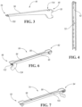
Figure 3 is a perspective view of a central support arm of a shelving system. -
Figure 4 is a perspective view of a support ladder of the shelving system. -
Figure 5 is a cross-sectional view of a rear portion of a shelf of the shelving system. -
Figure 6 is a perspective view of a rear support member of the shelving system. -
Figure 7 is a perspective view of another rear support member of the shelving system. -
Figure 8 is a partial perspective view of the shelving system installed within the refrigerator appliance. -
Figure 9 is a perspective view of a connector of the rear support member ofFigure 6 . -
Figure 10 is a perspective view, in cross section, of another connector of the rear support member ofFigure 6 . -
Figure 11 is a perspective view, in cross section, of a connector of a front support member of the shelving system. - As required, detailed embodiments of the present invention are disclosed herein; however, it is to be understood that the disclosed embodiments are merely exemplary of the invention that may be embodied in various and alternative forms. The figures are not necessarily to scale; some features may be exaggerated or minimized to show details of particular components. Therefore, specific structural and functional details disclosed herein are not to be interpreted as limiting, but merely as a representative basis for teaching one skilled in the art to variously employ the present invention.
- Referring to
Figures 1 and2 , arefrigerator appliance 20 includes an outer housing or cabinet (not shown) that forms the exterior of theappliance 20. Within the cabinet are one or more compartments or cavities such as a fresh-food compartment 24 and a freezer compartment. Therefrigerator appliance 20 may include one or more liners that define the compartments. For example, aliner 22 defines the fresh-food compartment 24. Theliner 22 includes aback wall 26, a top wall 28 abottom wall 30, and opposing first andsecond sidewalls cavity 24. While not shown, a second liner may be used to form the freezer compartment. The freezer compartment may be disposed above or below the fresh-food compartment 24. In one embodiment, therefrigerator appliance 20 is a so-called "French-style refrigerator" having the fresh-food compartment 24 on top and the freezer compartment below. One or more doors (not shown) are attached to the cabinet to seal the one or more compartments. - The
refrigerator 20 includes an air circulation system for cooling thecompartment 24. The air circulation system may include acover 36 disposed against theback wall 26 of theliner 22. An air gap may be provided between theback wall 26 and thecover 36. Thecover 36 may define avertical slot 38 centered on theback wall 26 such that a first distance between the first sidewall and the ladder is substantially equal to a second distance between the second sidewall and the ladder. Herein, substantially equal means within 5 percent. Additional openings may be provided in thecover 36 in addition to the vertical slot. Of course, other types of air circulation systems are contemplated, and this disclosure is not limited to systems that include thecover 36. - The
refrigerator appliance 20 has ashelving system 40 configured to support food items stored within the fresh-food compartment 24. Theshelving system 40 includes an elongate shelf-support ladder 42 arranged vertically on theback wall 24 and positioned centrally. Thesupport ladder 42 may be received in theslot 38 and secured to theliner 22 by fasteners or other joining techniques. Theladder 42 forms the backbone of theshelving system 40 and is a main structural component. One ormore shelf assemblies 46 of thesystem 40 are supported by theladder 42. - Referring to
Figures 3 and 4 , eachshelf assembly 46 may include acentral arm 44 attached to thesupport ladder 42. Thecentral arm 44 has arear portion 48 configured to connect with theladder 42. Therear portion 48 may include connection features 50, e.g., hooks, configured to engage with connection features 52, e.g., slots or openings, of theladder 42. The arm is 44 designed to only attach at therear portion 48 and cantilever from theladder 42. Theladder 42 has a plurality of connection features 52 allowing thearm 44 to be placed at various heights. Thearm 44 extends forwardly from therear portion 48 located at a back of fresh-food compartment 24 to afront portion 54 located at the front of the fresh-food compartment 24. Thearm 44 includes a planartop surface 56 that generally extends between therear portion 48 and thefront portion 54. - Referring back to
Figures 1 and2 , eachshelf assembly 46 further includes a pair ofhalf shelves central arm 44. Thehalf shelf 58 may include apane 62, e.g., glass, a rear support member orbrace 64 and a front support member orbrace 66. Thepane 62 includes anupper surface 63 configured to support food items and alower surface 65. Therear support member 64 is received on arear edge 68 of thepane 62. Thefront support member 66 is received on afront edge 70 of thepane 62. Thehalf shelf 60 may include apane 72, e.g., glass, a rear support member orbrace 74 and a front support member orbrace 76. Thepane 72 includes anupper surface 73 configured to support food items and alower surface 75. Therear support member 74 is received on arear edge 78 of thepane 62. Thefront support member 66 is received on afront edge 80 of thepane 72. - Referring to
Figure 6 , therear support 64 may be an elongate member having aninside end 82 and anoutside end 86. Achannel 84 may extend between theinside end 82 and theoutside end 86 and has an upperplanar portion 88 and a lowerplanar portion 90. Thechannel 84 is configured to receive therear edge 68 of thepane 62 therein with the upperplanar portion 88 disposed on theupper surface 63 and the lowerplanar portion 90 disposed against thelower surface 65. The length of thechannel 84 may be substantially the same as the length of therear edge 68. - Referring to
Figure 7 , therear support 74 may be an elongate member having aninside end 92 andoutside end 94. Achannel 96 may extend between theinside end 92 and theoutside end 94 and has an upperplanar portion 98 and a lowerplanar portion 100. Thechannel 96 is configured to receive therear edge 78 of thepane 72 therein with the upperplanar portion 98 disposed on theupper surface 73 and the lowerplanar portion 100 disposed against thelower surface 75. The length of thechannel 96 may be substantially the same as the length of therear edge 78. - Referring to
Figure 5 , therear support 64 and thepane 62 may include connection features for securing therear support 64 to thepane 62. In one embodiment, thepane 62 defines agroove 102 recessed into thebottom surface 65 and extending in the width direction of thepane 62. Thegroove 102 is located near therear edge 68 so that it is received within thechannel 84. Thegroove 102 may or may not extend across the entire width of thepane 62. In some embodiments, thegroove 102 may be a plurality of discontinuous grooves that are linearly arranged in the width direction. - The
rear support 64 may include aprojection 104 that is located within thechannel 84 and configured to be received within thegroove 102. Theprojection 104 may extend in the width direction, i.e., between the inner and outer ends 82/86. In the illustrated embodiment, theprojection 104 extends upwardly from the lowerplanar portion 90. In some embodiments, theprojection 104 may be a plurality of discontinuous projections that are linearly arranged in the width direction to match the discontinuous grooves of thepane 62. - While the
groove 102 and theprojection 104 are illustrate as being on the bottom, they can be flipped in other embodiments and be provided on the top. In other embodiments, the projection may be of thepane 62 and the groove may be formed in therear support 64. - The
rear support 74 may be attached to thepane 72 in the same or similar way as described above with regards topane 62 andrear support 64. For brevity, this connection will not be described again. In some embodiments, the pair of rear supports may instead be a single rear support for both panes. - Referring to
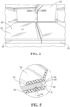
Figures 8 and 9 , in one or more embodiments, each half shelf is supported centrally by thearm 44 and on the outside by a support member of theliner 22. For example, thesidewall 32 of theliner 22 defines asupport rail 110 configured to engage with therear support 64. Thesupport rail 110 may be an integrally formed feature of theliner 22 or maybe a standalone component that is attached to theliner 22. Thesupport rail 110 projects outwardly from thesidewall 32 and includes a top 112 and a bottom 114. The top 112 may include aplanar surface 116 configured to engage with thebottom side 65 of thepane 62. Asecond support rail 118 may be placed in front of thesupport rail 110 and is also configured to engage with thebottom side 65 of thepane 62. Thefront support rail 118 may be smaller than therear support rail 110. - The
rear support member 64 may have aconnector 120 that is rotatably connected to thesupport rail 110 such that thefirst shelf 58 is pivotal relative to thesupport rail 110. Theconnector 120 may include aplanar portion 122 configured to rest on the top 112 of thesupport rail 110 and ahooked portion 124 configured to partially extend around therail 110. Theplanar portion 122 may include a plurality ofribs 126. - Referring to
Figures 8 and 10 , thearm 44 may have first and second opposingsidewalls arm 44 is generally hollow. Each of thesidewalls rear portion 48 to thetip 54 of thearm 44. Therear support 64 may be supported by thefirst sidewall 130 and therear support 74 is supported by thesecond sidewall 132. Thecentral arm 44 may define a rear cut out 134 in thetop surface 56 allowing the rear supports 64, 74 to engage with thesidewalls - In one example embodiment, the
rear support 64 includes aconnector 136 configured to connect therear support 64 to thecentral arm 44. Theconnector 136 may be received on atop edge 138 of thefirst sidewall 130. Theconnector 136 may include aninner member 140 depending downwardly into thearm 44 and configured to be received against the inner surface 141 of thesidewall 130. Theconnector 136 may also include ananti-rotation tab 142 disposed on the outside of thearm 44 and configured to engage with theouter surface 144 of thesidewall 130. Theanti-rotation tab 142 inhibits excessive rotation of theshelf 58 in the downward direction. - Referring to
Figures 8 and 11 , the front supports 66 and 76 may also attached to thecentral arm 44. For example, thefront support 66 may include aconnector 146 that is received within a slot or opening 150 of thecentral arm 44. Theconnector 146 may also be received on thefirst sidewall 130. Theconnector 146 may include first andsecond portions vertical slot 156 received on thesidewall 130. - The
shelf 58 may be installed by positioning theshelf 58 at an angle and aligning thepane 62 onto the front and rear support rails 118 and 110 with theconnector 120 of therear bracket 64 received around therear support rail 110. Theshelf 58 is then pivoted downwardly until theconnector 34 of therear support 64 and theconnector 154 of the front support engage with thecentral arm 44. Thelower side 65 of thepane 62 is supported by theupper surface 56 of thearm 44. - For brevity, only the connections for the
shelf 58 are described. However, it is to be understood that the other shelves may be supported within therefrigerator appliance 20 in a similar or same manner. Only one shelve assembly is shown, it is to be understood that theladder 42 can support a plurality of shelve assemblies that are arranged vertically relative to each other.
Claims (15)
- A refrigerator appliance (20) comprising:a liner (22) defining at least one cavity (24), the cavity (24) being in particular configured to act as a fresh-food storage compartment, the liner (22) having a back wall (26) and opposing first and second sidewalls (32, 34);a ladder (42) configured to act as a shelf-support ladder (42) and positioned centrally on the back wall (26);an arm (44) having a rear portion (48) attached to the ladder (42) such that the arm (44) is cantilevered from the ladder (42); anda shelf assembly (46) supported by the arm (44) and including a first shelf surface (63) located between the first sidewall (32) and the arm (44) and a second shelf surface (73) located between the second sidewall (34) and the arm (44).
- The refrigerator appliance (20) of claim 1, wherein the ladder (42) is formed by an elongated body arranged vertically such that a first distance between the first sidewall (32) and the ladder (42) is substantially equal to a second distance between the second sidewall (34) and the ladder (42) and/or wherein the refrigerator appliance (20) includes only one ladder (42) in the cavity (24) and/or wherein the ladder (42) is fixed to the liner (22), in particular screwed to the liner (22).
- The refrigerator appliance (20) of claim 1 or claim 2, wherein the shelf assembly (46) includes at least a first pane (62) defining at least the first shelf surface (63), optionally wherein the shelf assembly (46) includes a first pane (62) defining the first shelf surface (63) and a second pane (72) defining the second shelf surface (73), the first pane (62) and/or the second pane (72) being in particular made of glass.
- The refrigerator appliance (20) of claim 3, wherein the shelf assembly (46) further includes a rear support, in particular a plastic rear support, connecting at least the first pane (62) to the arm (44), optionally wherein the rear support is arranged orthogonal to the arm (44).
- The refrigerator appliance (20) of claim 4, wherein the rear support defines a channel (84) and a rear edge (68) of the first pane (62) is received in the channel (84), optionally wherein one between the first pane (62) and the rear support defines a groove (102) and the other between the first pane (62) and the rear support has a projection (104), the projection being received in the groove (102) to secure the first pane (62) to the rear support (64), optionally wherein the first pane (62) defines the groove (102) and the rear support has the projection (104) adjacent to the channel (84).
- The refrigerator appliance (20) of claim 3, wherein the shelf assembly (46) further includes a first rear bracket (64) connected to the arm (44) and extending toward the first sidewall (32), the first rear bracket (64) supporting in particular the first pane (62) to the arm (44), and a second rear bracket (74) connected to the arm (44) and extending toward the second sidewall (34), the second rear bracket (74) supporting in particular the second pane (72) to the arm (44), optionally wherein the first rear bracket (64) defines a channel (84) that receives a rear edge (68) of the first pane (62) and the second rear bracket (74) defines a channel (96) that receives a rear edge (78) of the second pane (72).
- The refrigerator appliance (20) of claim 6, the first sidewall (32) of the liner (22) defining a first support rail (110) configured to engage with the first rear bracket (64) and the second sidewall (34) of the liner (22) defining a second support rail configured to engage with the second rear bracket (74), wherein the first rear bracket (64) and the second rear bracket (74) comprise a connector (120) rotatably and/or slidably connected to respective support rail, optionally wherein he connector (120) includes a planar portion (122) configured to rest on a top (112) of the respective support rail and a hooked portion (124) configured to partially extend around the respective support rail.
- The refrigerator appliance (20) of any one of the previous claims, wherein the arm (44) is a metallic bent component having a top surface (56) and first and second opposing sidewalls (130, 132), wherein the first and second opposing sidewalls (130, 132) are spaced apart from each other such that a hollow interior of the arm (44) is defined.
- The refrigerator appliance (20) of claim 8, wherein the first rear bracket (64) includes a top connector (136) received on a top edge (138) of the first sidewall (130) and the second rear bracket (74) includes a top connector (136) received on a top edge (138) of the second sidewall (132), in particular wherein each top connector (136) includes an anti-rotation tab (142) configured to engage with a corresponding one of the first and second sidewalls (130, 132) of the arm (44), and/or wherein the first rear bracket (64) includes a side connector (146) received on the first sidewall (130) and the second rear bracket (74) includes a side connector received on the second sidewall (132), in particular wherein the side connector (146) includes first and second portions (152, 154) cooperating to define a vertical slot (156) received on a corresponding one of the first and second sidewalls (130, 132).
- The refrigerator appliance (20) of claim 8 or claim 9, further comprising a cover arm, in particular a plastic cover arm, wherein the cover arm is connected to the arm (44) such that the interior of the arm (44) is made inaccessible, optionally wherein the cover arm is connected to the arm (44) through a snap-fit system.
- The refrigerator appliance (20) of any one of claims 3 to 10, wherein the arm (44) or the cover arm comprises a rib, in particular a frontal rib, extending above the top surface (56) of the arm (44), wherein the rib is configured to avoid side displacements between the first pane (62) and the second pane (72).
- The refrigerator appliance (20) of any one of claims 3 to 11, wherein the shelf assembly (46) further includes a first front bracket (66) connected to the arm (44) and extending toward the first sidewall (32) and a second front bracket (76) connected to the arm (44) and extending toward the second sidewall (34), optionally wherein the first front bracket (66) supports the first pane (62) to the arm (44) and the second front bracket (76) supports the second pane (72) to the arm (44).
- The refrigerator appliance (20) of any one of claims 1 to 12, further comprising a cover (36), in particular a plastic cover (36), disposed on the back wall (26) and defining a slot (38), wherein the ladder (42) is disposed in the slot (38), optionally wherein the cover (36) is fixed to the liner (22) by means of screws and/or snap-fit connectors and/or wherein the cover (36) includes a plurality of openings at different heights, such that the cover (36) acts, in combination with the liner (22), as a multiflow channel.
- The refrigerator appliance (20) of any one of claims 1 to 13, wherein the ladder (42) comprises a main wall, a plurality of connection features (52), in particular a plurality of slots or openings, configured to engage with a plurality of connection features (50), in particular a plurality of hooks, of the arm (44), is obtained in the main wall such that the arm (44) may be accommodated in the cavity (24) at different heights, optionally wherein the ladder (42) further comprises a pair of lateral walls extending from opposite edges of the main wall, the lateral walls and the main wall defining in combination a receptacle, the rear portion (48) of the arm (44) being at least partly accommodated in the receptacle.
- The refrigerator appliance (20) of any one of claims 1 to 14, wherein the arm (44) is made of a dishwasher safe material and/or wherein the cover arm is made of a dishwasher safe material and/or wherein at least one component of the shelf assembly (46) is made of a dishwasher safe material, in particular the first pane (62) and/or the second pane (72) and/or the first rear bracket (64) and/or the second rear bracket (74) and/or the first front bracket (66) and/or the second front bracket (76) being made of a dishwasher safe material.
Applications Claiming Priority (1)
| Application Number | Priority Date | Filing Date | Title |
|---|---|---|---|
| US18/162,863 US12253302B2 (en) | 2023-02-01 | 2023-02-01 | Refrigerator appliance with two half shelves supported by a cantilever arm |
Publications (1)
| Publication Number | Publication Date |
|---|---|
| EP4411295A1 true EP4411295A1 (en) | 2024-08-07 |
Family
ID=89767405
Family Applications (1)
| Application Number | Title | Priority Date | Filing Date |
|---|---|---|---|
| EP24154388.3A Pending EP4411295A1 (en) | 2023-02-01 | 2024-01-29 | Refrigerator appliance with two half shelves supported by a cantilever arm |
Country Status (2)
| Country | Link |
|---|---|
| US (1) | US12253302B2 (en) |
| EP (1) | EP4411295A1 (en) |
Cited By (1)
| Publication number | Priority date | Publication date | Assignee | Title |
|---|---|---|---|---|
| US12253302B2 (en) | 2023-02-01 | 2025-03-18 | Whirlpool Corporation | Refrigerator appliance with two half shelves supported by a cantilever arm |
Families Citing this family (1)
| Publication number | Priority date | Publication date | Assignee | Title |
|---|---|---|---|---|
| USD1058357S1 (en) * | 2024-06-18 | 2025-01-21 | Changzhou Joshua Home Furnishing Co., Ltd. | Plastic guide rail |
Citations (8)
| Publication number | Priority date | Publication date | Assignee | Title |
|---|---|---|---|---|
| US5340209A (en) * | 1992-12-28 | 1994-08-23 | General Electric Company | Slide-out shelf assembly for refrigerators |
| US5893620A (en) * | 1993-07-26 | 1999-04-13 | Whirlpool Corporation | Multiple shelf support system in common refrigerator liner |
| US6347530B1 (en) * | 1999-05-10 | 2002-02-19 | Lg Electronics Inc. | Cooling air supplying structure for a refrigerator having cantilever shelves |
| US20160278519A1 (en) * | 2015-03-23 | 2016-09-29 | Whirlpool Corporation | Concealed vertical adjustment mechanism for kitchen appliance storage members |
| US20180087828A1 (en) * | 2016-09-23 | 2018-03-29 | Samsung Electronics Co., Ltd. | Refrigerator |
| US20190360744A1 (en) * | 2017-12-08 | 2019-11-28 | Electrolux Home Products, Inc. | Dual asymmetrical and symmetrical architecture cantilever positioning |
| US20210102750A1 (en) * | 2018-03-02 | 2021-04-08 | Electrolux Do Brasil S.A. | Storage structure for refrigerator appliance |
| US20210222945A1 (en) * | 2020-01-16 | 2021-07-22 | Electrolux Home Products, Inc. | Cantilever shelf and shelf support assembly |
Family Cites Families (9)
| Publication number | Priority date | Publication date | Assignee | Title |
|---|---|---|---|---|
| DE102009027886A1 (en) | 2009-07-21 | 2011-01-27 | BSH Bosch und Siemens Hausgeräte GmbH | Domestic refrigerating appliance with intermediate bottom and method for producing the intermediate bottom |
| US8282178B2 (en) | 2010-02-16 | 2012-10-09 | Whirlpool Corporation | Non-encapsulated refrigerator shelf |
| CN205641793U (en) * | 2016-05-21 | 2016-10-12 | 滁州克莱帝玻璃科技有限公司 | Modular refrigerator is fixing clip for glass shelf |
| KR102519048B1 (en) | 2016-07-14 | 2023-04-07 | 삼성전자주식회사 | Refrigerator |
| US10634420B2 (en) * | 2018-05-25 | 2020-04-28 | Haier Us Appliance Solutions, Inc. | Liner supported shelf assembly for a refrigerator appliance |
| KR102559744B1 (en) * | 2018-06-20 | 2023-07-28 | 삼성전자주식회사 | Refrigerator |
| US10670327B1 (en) | 2018-12-07 | 2020-06-02 | Bsh Hausgeraete Gmbh | Household cooling appliance comprising a shelf device |
| TR201912527A2 (en) | 2019-08-21 | 2021-03-22 | Bsh Ev Aletleri San Ve Tic As | Storage rack with central bar specific for separate plate portions |
| US12253302B2 (en) | 2023-02-01 | 2025-03-18 | Whirlpool Corporation | Refrigerator appliance with two half shelves supported by a cantilever arm |
-
2023
- 2023-02-01 US US18/162,863 patent/US12253302B2/en active Active
-
2024
- 2024-01-29 EP EP24154388.3A patent/EP4411295A1/en active Pending
Patent Citations (8)
| Publication number | Priority date | Publication date | Assignee | Title |
|---|---|---|---|---|
| US5340209A (en) * | 1992-12-28 | 1994-08-23 | General Electric Company | Slide-out shelf assembly for refrigerators |
| US5893620A (en) * | 1993-07-26 | 1999-04-13 | Whirlpool Corporation | Multiple shelf support system in common refrigerator liner |
| US6347530B1 (en) * | 1999-05-10 | 2002-02-19 | Lg Electronics Inc. | Cooling air supplying structure for a refrigerator having cantilever shelves |
| US20160278519A1 (en) * | 2015-03-23 | 2016-09-29 | Whirlpool Corporation | Concealed vertical adjustment mechanism for kitchen appliance storage members |
| US20180087828A1 (en) * | 2016-09-23 | 2018-03-29 | Samsung Electronics Co., Ltd. | Refrigerator |
| US20190360744A1 (en) * | 2017-12-08 | 2019-11-28 | Electrolux Home Products, Inc. | Dual asymmetrical and symmetrical architecture cantilever positioning |
| US20210102750A1 (en) * | 2018-03-02 | 2021-04-08 | Electrolux Do Brasil S.A. | Storage structure for refrigerator appliance |
| US20210222945A1 (en) * | 2020-01-16 | 2021-07-22 | Electrolux Home Products, Inc. | Cantilever shelf and shelf support assembly |
Cited By (1)
| Publication number | Priority date | Publication date | Assignee | Title |
|---|---|---|---|---|
| US12253302B2 (en) | 2023-02-01 | 2025-03-18 | Whirlpool Corporation | Refrigerator appliance with two half shelves supported by a cantilever arm |
Also Published As
| Publication number | Publication date |
|---|---|
| US12253302B2 (en) | 2025-03-18 |
| US20240255214A1 (en) | 2024-08-01 |
Similar Documents
| Publication | Publication Date | Title |
|---|---|---|
| US5004302A (en) | Shelf support system for split cantilever shelves | |
| US9448007B2 (en) | Shelving assembly for refrigerator compartment | |
| US9759479B2 (en) | Appliance modular system for incorporating a pantry compartment within an appliance | |
| US5893620A (en) | Multiple shelf support system in common refrigerator liner | |
| US12253302B2 (en) | Refrigerator appliance with two half shelves supported by a cantilever arm | |
| US8282178B2 (en) | Non-encapsulated refrigerator shelf | |
| US20030011291A1 (en) | Storage bin mounting system for a refrigerator door | |
| US10006693B2 (en) | Appliance modular system for incorporating a pantry compartment within an appliance | |
| US8721014B2 (en) | Refrigerator | |
| JP2001104117A (en) | Open showcase | |
| EP3725186A1 (en) | Trim assembly for an appliance shelf | |
| MXPA96006125A (en) | Pararefrigerated freezer compartment structure | |
| US12345465B2 (en) | Refrigerator appliance shelving system | |
| US11067331B1 (en) | Cantilever shelf and shelf support assembly | |
| US11221175B1 (en) | Liner hanger | |
| CN104541116B (en) | Soft freezing region | |
| CN221630098U (en) | Refrigerating appliance | |
| CN210227583U (en) | Horizontal freezing showcase | |
| US12460858B2 (en) | Snap fit attachment feature for a mullion assembly of a refrigerator appliance | |
| US11969092B2 (en) | Adjustable shelf support | |
| US20250024966A1 (en) | Refrigerator appliance | |
| KR200141807Y1 (en) | Tray of a refrigerator | |
| CN210663506U (en) | Wall-hung refrigerator | |
| KR20230116579A (en) | Refrigerator | |
| EP4018882A1 (en) | Refrigeration device |
Legal Events
| Date | Code | Title | Description |
|---|---|---|---|
| PUAI | Public reference made under article 153(3) epc to a published international application that has entered the european phase |
Free format text: ORIGINAL CODE: 0009012 |
|
| STAA | Information on the status of an ep patent application or granted ep patent |
Free format text: STATUS: THE APPLICATION HAS BEEN PUBLISHED |
|
| AK | Designated contracting states |
Kind code of ref document: A1 Designated state(s): AL AT BE BG CH CY CZ DE DK EE ES FI FR GB GR HR HU IE IS IT LI LT LU LV MC ME MK MT NL NO PL PT RO RS SE SI SK SM TR |
|
| RAP1 | Party data changed (applicant data changed or rights of an application transferred) |
Owner name: BEKO EUROPE MANAGEMENT S.R.L. |
|
| P01 | Opt-out of the competence of the unified patent court (upc) registered |
Free format text: CASE NUMBER: APP_59209/2024 Effective date: 20241030 |
|
| STAA | Information on the status of an ep patent application or granted ep patent |
Free format text: STATUS: REQUEST FOR EXAMINATION WAS MADE |
|
| 17P | Request for examination filed |
Effective date: 20250122 |