EP4411290A1 - Refrigeration cycle device - Google Patents
Refrigeration cycle device Download PDFInfo
- Publication number
- EP4411290A1 EP4411290A1 EP22876056.7A EP22876056A EP4411290A1 EP 4411290 A1 EP4411290 A1 EP 4411290A1 EP 22876056 A EP22876056 A EP 22876056A EP 4411290 A1 EP4411290 A1 EP 4411290A1
- Authority
- EP
- European Patent Office
- Prior art keywords
- refrigerant
- connecting portion
- primary
- pipe
- utilization
- Prior art date
- Legal status (The legal status is an assumption and is not a legal conclusion. Google has not performed a legal analysis and makes no representation as to the accuracy of the status listed.)
- Granted
Links
Images




Classifications
-
- F—MECHANICAL ENGINEERING; LIGHTING; HEATING; WEAPONS; BLASTING
- F25—REFRIGERATION OR COOLING; COMBINED HEATING AND REFRIGERATION SYSTEMS; HEAT PUMP SYSTEMS; MANUFACTURE OR STORAGE OF ICE; LIQUEFACTION SOLIDIFICATION OF GASES
- F25B—REFRIGERATION MACHINES, PLANTS OR SYSTEMS; COMBINED HEATING AND REFRIGERATION SYSTEMS; HEAT PUMP SYSTEMS
- F25B49/00—Arrangement or mounting of control or safety devices
- F25B49/02—Arrangement or mounting of control or safety devices for compression type machines, plants or systems
-
- F—MECHANICAL ENGINEERING; LIGHTING; HEATING; WEAPONS; BLASTING
- F25—REFRIGERATION OR COOLING; COMBINED HEATING AND REFRIGERATION SYSTEMS; HEAT PUMP SYSTEMS; MANUFACTURE OR STORAGE OF ICE; LIQUEFACTION SOLIDIFICATION OF GASES
- F25B—REFRIGERATION MACHINES, PLANTS OR SYSTEMS; COMBINED HEATING AND REFRIGERATION SYSTEMS; HEAT PUMP SYSTEMS
- F25B1/00—Compression machines, plants or systems with non-reversible cycle
-
- F—MECHANICAL ENGINEERING; LIGHTING; HEATING; WEAPONS; BLASTING
- F25—REFRIGERATION OR COOLING; COMBINED HEATING AND REFRIGERATION SYSTEMS; HEAT PUMP SYSTEMS; MANUFACTURE OR STORAGE OF ICE; LIQUEFACTION SOLIDIFICATION OF GASES
- F25B—REFRIGERATION MACHINES, PLANTS OR SYSTEMS; COMBINED HEATING AND REFRIGERATION SYSTEMS; HEAT PUMP SYSTEMS
- F25B13/00—Compression machines, plants or systems, with reversible cycle
-
- F—MECHANICAL ENGINEERING; LIGHTING; HEATING; WEAPONS; BLASTING
- F25—REFRIGERATION OR COOLING; COMBINED HEATING AND REFRIGERATION SYSTEMS; HEAT PUMP SYSTEMS; MANUFACTURE OR STORAGE OF ICE; LIQUEFACTION SOLIDIFICATION OF GASES
- F25B—REFRIGERATION MACHINES, PLANTS OR SYSTEMS; COMBINED HEATING AND REFRIGERATION SYSTEMS; HEAT PUMP SYSTEMS
- F25B41/00—Fluid-circulation arrangements
- F25B41/20—Disposition of valves, e.g. of on-off valves or flow control valves
-
- F—MECHANICAL ENGINEERING; LIGHTING; HEATING; WEAPONS; BLASTING
- F25—REFRIGERATION OR COOLING; COMBINED HEATING AND REFRIGERATION SYSTEMS; HEAT PUMP SYSTEMS; MANUFACTURE OR STORAGE OF ICE; LIQUEFACTION SOLIDIFICATION OF GASES
- F25B—REFRIGERATION MACHINES, PLANTS OR SYSTEMS; COMBINED HEATING AND REFRIGERATION SYSTEMS; HEAT PUMP SYSTEMS
- F25B41/00—Fluid-circulation arrangements
- F25B41/20—Disposition of valves, e.g. of on-off valves or flow control valves
- F25B41/26—Disposition of valves, e.g. of on-off valves or flow control valves of fluid flow reversing valves
-
- F—MECHANICAL ENGINEERING; LIGHTING; HEATING; WEAPONS; BLASTING
- F25—REFRIGERATION OR COOLING; COMBINED HEATING AND REFRIGERATION SYSTEMS; HEAT PUMP SYSTEMS; MANUFACTURE OR STORAGE OF ICE; LIQUEFACTION SOLIDIFICATION OF GASES
- F25B—REFRIGERATION MACHINES, PLANTS OR SYSTEMS; COMBINED HEATING AND REFRIGERATION SYSTEMS; HEAT PUMP SYSTEMS
- F25B41/00—Fluid-circulation arrangements
- F25B41/40—Fluid line arrangements
-
- F—MECHANICAL ENGINEERING; LIGHTING; HEATING; WEAPONS; BLASTING
- F25—REFRIGERATION OR COOLING; COMBINED HEATING AND REFRIGERATION SYSTEMS; HEAT PUMP SYSTEMS; MANUFACTURE OR STORAGE OF ICE; LIQUEFACTION SOLIDIFICATION OF GASES
- F25B—REFRIGERATION MACHINES, PLANTS OR SYSTEMS; COMBINED HEATING AND REFRIGERATION SYSTEMS; HEAT PUMP SYSTEMS
- F25B43/00—Arrangements for separating or purifying gases or liquids; Arrangements for vaporising the residuum of liquid refrigerant, e.g. by heat
-
- F—MECHANICAL ENGINEERING; LIGHTING; HEATING; WEAPONS; BLASTING
- F25—REFRIGERATION OR COOLING; COMBINED HEATING AND REFRIGERATION SYSTEMS; HEAT PUMP SYSTEMS; MANUFACTURE OR STORAGE OF ICE; LIQUEFACTION SOLIDIFICATION OF GASES
- F25B—REFRIGERATION MACHINES, PLANTS OR SYSTEMS; COMBINED HEATING AND REFRIGERATION SYSTEMS; HEAT PUMP SYSTEMS
- F25B45/00—Arrangements for charging or discharging refrigerant
-
- F—MECHANICAL ENGINEERING; LIGHTING; HEATING; WEAPONS; BLASTING
- F25—REFRIGERATION OR COOLING; COMBINED HEATING AND REFRIGERATION SYSTEMS; HEAT PUMP SYSTEMS; MANUFACTURE OR STORAGE OF ICE; LIQUEFACTION SOLIDIFICATION OF GASES
- F25B—REFRIGERATION MACHINES, PLANTS OR SYSTEMS; COMBINED HEATING AND REFRIGERATION SYSTEMS; HEAT PUMP SYSTEMS
- F25B49/00—Arrangement or mounting of control or safety devices
- F25B49/005—Arrangement or mounting of control or safety devices of safety devices
-
- F—MECHANICAL ENGINEERING; LIGHTING; HEATING; WEAPONS; BLASTING
- F25—REFRIGERATION OR COOLING; COMBINED HEATING AND REFRIGERATION SYSTEMS; HEAT PUMP SYSTEMS; MANUFACTURE OR STORAGE OF ICE; LIQUEFACTION SOLIDIFICATION OF GASES
- F25B—REFRIGERATION MACHINES, PLANTS OR SYSTEMS; COMBINED HEATING AND REFRIGERATION SYSTEMS; HEAT PUMP SYSTEMS
- F25B9/00—Compression machines, plants or systems, in which the refrigerant is air or other gas of low boiling point
- F25B9/002—Compression machines, plants or systems, in which the refrigerant is air or other gas of low boiling point characterised by the refrigerant
- F25B9/008—Compression machines, plants or systems, in which the refrigerant is air or other gas of low boiling point characterised by the refrigerant the refrigerant being carbon dioxide
-
- F—MECHANICAL ENGINEERING; LIGHTING; HEATING; WEAPONS; BLASTING
- F25—REFRIGERATION OR COOLING; COMBINED HEATING AND REFRIGERATION SYSTEMS; HEAT PUMP SYSTEMS; MANUFACTURE OR STORAGE OF ICE; LIQUEFACTION SOLIDIFICATION OF GASES
- F25B—REFRIGERATION MACHINES, PLANTS OR SYSTEMS; COMBINED HEATING AND REFRIGERATION SYSTEMS; HEAT PUMP SYSTEMS
- F25B2400/00—Component parts or details not otherwise provided for in this subclass
- F25B2400/16—Receivers
-
- F—MECHANICAL ENGINEERING; LIGHTING; HEATING; WEAPONS; BLASTING
- F25—REFRIGERATION OR COOLING; COMBINED HEATING AND REFRIGERATION SYSTEMS; HEAT PUMP SYSTEMS; MANUFACTURE OR STORAGE OF ICE; LIQUEFACTION SOLIDIFICATION OF GASES
- F25B—REFRIGERATION MACHINES, PLANTS OR SYSTEMS; COMBINED HEATING AND REFRIGERATION SYSTEMS; HEAT PUMP SYSTEMS
- F25B2500/00—Problems to be solved
- F25B2500/07—Exceeding a certain pressure value in a refrigeration component or cycle
-
- F—MECHANICAL ENGINEERING; LIGHTING; HEATING; WEAPONS; BLASTING
- F25—REFRIGERATION OR COOLING; COMBINED HEATING AND REFRIGERATION SYSTEMS; HEAT PUMP SYSTEMS; MANUFACTURE OR STORAGE OF ICE; LIQUEFACTION SOLIDIFICATION OF GASES
- F25B—REFRIGERATION MACHINES, PLANTS OR SYSTEMS; COMBINED HEATING AND REFRIGERATION SYSTEMS; HEAT PUMP SYSTEMS
- F25B2600/00—Control issues
- F25B2600/25—Control of valves
- F25B2600/2525—Pressure relief valves
Definitions
- the present disclosure relates to a refrigeration cycle apparatus.
- a receiver for reserving a refrigerant has been used in a refrigerant circuit included in a refrigeration cycle apparatus.
- Patent Literature 1 JP H07-324828 A
- a high-pressure receiver, an intermediate-pressure receiver, and the like are used in a refrigerant circuit.
- a safety valve is connected in a pressure vessel such as a receiver to secure reliability of the apparatus.
- the safety valve connected to a refrigerant vessel may be inspected for safety in a predetermined period such as one year because there is a possibility that defects such as aging can occur. During this inspection, the safety valve to be inspected is detached from the refrigerant vessel. Then, the safety valve inspected to have no problem is connected to the refrigerant vessel again.
- a refrigeration cycle apparatus includes a refrigerant circuit, a flow path switching portion, and a safety valve.
- the refrigerant circuit includes a refrigerant vessel that reserves a refrigerant.
- the flow path switching portion includes a first connecting portion, a second connecting portion, and a third connecting portion.
- the third connecting portion is connected to the refrigerant vessel.
- the flow path switching portion switches between a first state in which the third connecting portion communicates with the first connecting portion and a second state in which the third connecting portion communicates with the second connecting portion.
- the safety valve releases the refrigerant to outside when a refrigerant pressure in the refrigerant vessel satisfies a predetermined condition.
- the safety valve includes a fourth connecting portion.
- the fourth connecting portion is connected to the first connecting portion or the second connecting portion. At least the fourth connecting portion of the safety valve is made of stainless steel. A potential difference between the first connecting portion and the fourth connecting portion is 0.35 V or less. A potential difference between the second connecting portion and the fourth connecting portion is 0.35 V or less. An allowable tensile stress of the fourth connecting portion with respect to an allowable tensile stress of the first connecting portion (the allowable tensile stress of the fourth connecting portion/the allowable tensile stress of the first connecting portion) is 3.0 times or less.
- An allowable tensile stress of the fourth connecting portion with respect to the allowable tensile stress of the second connecting portion is 3.0 times or less.
- the potential difference between the first connecting portion and the fourth connecting portion is preferably 0.3 V or less, the potential difference between the second connecting portion and the fourth connecting portion is preferably 0.3 V or less, the potential difference between the first connecting portion and the fourth connecting portion is more preferably 0.2 V or less, and the potential difference between the second connecting portion and the fourth connecting portion is more preferably 0.2 V or less.
- the potential difference may be a value measured under the condition of 10°C to 27°C at a flow rate of 24 m/s to 40 m/s in seawater.
- the allowable tensile stress of the fourth connecting portion with respect to the allowable tensile stress of the first connecting portion is preferably 2.5 times or less
- the allowable tensile stress of the fourth connecting portion with respect to the allowable tensile stress of the second connecting portion is preferably 2.5 times or less
- the allowable tensile stress of the fourth connecting portion with respect to the allowable tensile stress of the first connecting portion is more preferably 2.0 times or less
- the allowable tensile stress of the fourth connecting portion with respect to the allowable tensile stress of the second connecting portion is more preferably 2.0 times or less.
- the safety valve having the fourth connecting portion preferably has a first safety valve in which the fourth connecting portion is connected to the first connecting portion, and a second safety valve in which the fourth connecting portion is connected to the second connecting portion.
- the fourth connecting portion of the safety valve is made of stainless steel, a strength of the connecting portion of the safety valve is secured.
- the potential difference between the first connecting portion and the fourth connecting portion and the potential difference between the second connecting portion and the fourth connecting portion are 0.35 V or less, metal corrosion when the safety valve is connected is suppressed.
- the allowable tensile stress of the fourth connecting portion with respect to the allowable tensile stress of the first connecting portion and the allowable tensile stress of the fourth connecting portion with respect to the allowable tensile stress of the second connecting portion are 3.0 times or less, damage generated in the first connecting portion or the second connecting portion by attachment and detachment of the safety valve is suppressed.
- a refrigeration cycle apparatus is the refrigeration cycle apparatus according to the first aspect, in which the flow path switching portion includes a flow path switching valve having the third connecting portion, a first connecting pipe having the first connecting portion and connected to the flow path switching valve, and a second connecting pipe having the second connecting portion and connected to the flow path switching valve.
- the safety valve can be connected to the first connecting pipe and the second connecting pipe.
- a refrigeration cycle apparatus is the refrigeration cycle apparatus according to the first or second aspect, in which the first connecting portion is made of copper, a copper alloy, or stainless steel.
- the second connecting portion is made of copper, a copper alloy, or stainless steel.
- the refrigeration cycle apparatus can increase a strength of a portion to be connected to the safety valve.
- a refrigeration cycle apparatus is the refrigeration cycle apparatus according to any one of the first to third aspects, in which the first connecting portion and the second connecting portion is made of stainless steel.
- stainless steel examples of the stainless steel is made of SUS such as SUS304, SUS316, SUS303, SUS410, and SUS430.
- This refrigeration cycle apparatus can sufficiently increase the strength of the portion to be connected to the safety valve.
- a refrigeration cycle apparatus is the refrigeration cycle apparatus according to any one of the first to fourth aspects, in which the safety valve is a screw-type safety valve in which the fourth connecting portion has a screw thread.
- the safety valve is a screw-type safety valve in which the fourth connecting portion has a screw thread.
- Each of the first connecting portion and the second connecting portion of the flow path switching portion has a screw thread corresponding to the fourth connecting portion.
- the refrigeration cycle apparatus prevents the screw thread of the safety valve from crushing a screw groove of the first connecting portion or a screw groove of the second connecting portion.
- a refrigeration cycle apparatus is the refrigeration cycle apparatus according to any one of the first to fifth aspects, in which the refrigerant is a refrigerant containing a carbon dioxide refrigerant.
- the refrigeration cycle apparatus can still enhance reliability of the safety valve when a carbon dioxide refrigerant is used.
- a refrigeration cycle apparatus is the refrigeration cycle apparatus according to any one of the first to sixth aspects, in which the refrigerant vessel is provided at a portion of the refrigerant circuit in which a high-pressure refrigerant flows.
- the refrigeration cycle apparatus can enhance the reliability of the safety valve at a portion where the high-pressure refrigerant is reserved in a refrigeration cycle.
- FIG. 1 is a schematic configuration diagram of a refrigeration cycle apparatus 1.
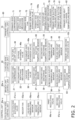
- FIG. 2 is a schematic functional block configuration diagram of the refrigeration cycle apparatus 1.
- the refrigeration cycle apparatus 1 is an apparatus used for cooling and heating of an indoor space in a building or the like by performing vapor compression refrigeration cycle operation.
- the refrigeration cycle apparatus 1 includes a binary refrigerant circuit including a vapor compression primary-side refrigerant circuit 5a (corresponding to a first circuit) and a vapor compression secondary-side refrigerant circuit 10 (corresponding to a refrigerant circuit), and performs a binary refrigeration cycle.
- a binary refrigerant circuit including a vapor compression primary-side refrigerant circuit 5a (corresponding to a first circuit) and a vapor compression secondary-side refrigerant circuit 10 (corresponding to a refrigerant circuit), and performs a binary refrigeration cycle.
- R32 or R410A is sealed as a refrigerant in the primary-side refrigerant circuit 5a.
- carbon dioxide is sealed as a refrigerant.
- the primary-side refrigerant circuit 5a and the secondary-side refrigerant circuit 10 are thermally connected via a cascade heat exchanger 35 described later.
- the refrigeration cycle apparatus 1 is configured by connecting a primary-side unit 5, a cascade unit 2, a plurality of branch units 6a, 6b, and 6c, and a plurality of utilization units 3a, 3b, and 3c to each other via pipes.
- the primary-side unit 5 and the cascade unit 2 are connected via a primary-side first connection pipe 111 and a primary-side second connection pipe 112.
- the cascade unit 2 and the plurality of branch units 6a, 6b, and 6c are connected via three refrigerant connection pipes, namely, a secondary-side second connection pipe 9, a secondary-side first connection pipe 8, and a secondary-side third connection pipe 7.
- the plurality of branch units 6a, 6b, and 6c and the plurality of utilization units 3a, 3b, and 3c are connected via first connecting tubes 15a, 15b, and 15c and second connecting tubes 16a, 16b, and 16c.
- the present embodiment provides the single primary-side unit 5.
- the present embodiment provides the single cascade unit 2.
- the plurality of utilization units 3a, 3b, and 3c according to the present embodiment includes three utilization units, namely, the first utilization unit 3a, the second utilization unit 3b, and the third utilization unit 3c.
- the plurality of branch units 6a, 6b, and 6c is three branch units, namely, the first branch unit 6a, the second branch unit 6b, and the third branch unit 6c.
- the utilization units 3a, 3b, and 3c can individually perform cooling operation or heating operation, and heat can be recovered between the utilization units by sending a refrigerant from the utilization unit performing the heating operation to the utilization unit performing the cooling operation. Specifically, heat is recovered in the present embodiment by performing cooling main operation or heating main operation of simultaneously performing cooling operation and heating operation.
- the refrigeration cycle apparatus 1 is configured to balance heat loads of the cascade unit 2 in accordance with entire heat loads of the plurality of utilization units 3a, 3b, and 3c also in consideration of the heat recovery (the cooling main operation or the heating main operation).
- the primary-side refrigerant circuit 5a includes a primary-side compressor 71, a primary-side switching mechanism 72, a primary-side heat exchanger 74, a primary-side first expansion valve 76, a primary-side subcooling heat exchanger 103, a primary-side subcooling circuit 104, a primary-side subcooling expansion valve 104a, a first liquid shutoff valve 108, the primary-side first connection pipe 111, a second liquid shutoff valve 106, the second refrigerant pipe 114, a primary-side second expansion valve 102, the cascade heat exchanger 35 shared with the secondary-side refrigerant circuit 10, a first refrigerant pipe 113, a second gas shutoff valve 107, the primary-side second connection pipe 112, a first gas shutoff valve 109, and a primary-side accumulator 105.
- This primary-side refrigerant circuit 5a specifically includes a primary-side flow path 35b of the cascade heat exchanger 35.
- the primary-side compressor 71 is a device for compressing a primary-side refrigerant, and includes, for example, a scroll type or other positive-displacement compressor whose operating capacity can be varied by controlling an inverter for a compressor motor 71a.
- the primary-side accumulator 105 is provided at a halfway portion of the suction flow path connecting the primary-side switching mechanism 72 and a suction side of the primary-side compressor 71.
- the primary-side switching mechanism 72 When the cascade heat exchanger 35 functions as an evaporator for the primary-side refrigerant, the primary-side switching mechanism 72 enters a fifth connection state of connecting the suction side of the primary-side compressor 71 and a gas side of a primary-side flow path 35b of the cascade heat exchanger 35 (see solid lines in the primary-side switching mechanism 72 in FIG. 1 ). When the cascade heat exchanger 35 functions as a radiator for the primary-side refrigerant, the primary-side switching mechanism 72 enters a sixth connection state of connecting a discharge side of the primary-side compressor 71 and the gas side of the primary-side flow path 35b of the cascade heat exchanger 35 (see broken lines in the primary-side switching mechanism 72 in FIG. 1 ).
- the primary-side switching mechanism 72 is a device that can switch the flow path of the refrigerant in the primary-side refrigerant circuit 5a, and includes, for example, a four-way switching valve. Then, by changing a switching state of the primary-side switching mechanism 72, the cascade heat exchanger 35 can function as the evaporator or the radiator for the primary-side refrigerant.
- the cascade heat exchanger 35 is a device for causing heat exchange between a refrigerant such as R32 which is a primary-side refrigerant and a refrigerant such as carbon dioxide which is a secondary-side refrigerant without mixing the refrigerants with each other.
- the cascade heat exchanger 35 is, for example, a plate-type heat exchanger.
- the cascade heat exchanger 35 includes a secondary-side flow path 35a belonging to the secondary-side refrigerant circuit 10 and the primary-side flow path 35b belonging to the primary-side refrigerant circuit 5a.
- the secondary-side flow path 35a has a gas side connected to a secondary-side switching mechanism 22 via a third pipe 25, and a liquid side connected to a cascade expansion valve 36 via a fourth pipe 26.
- the primary-side flow path 35b has a gas side connected to the primary-side compressor 71 via the first refrigerant pipe 113, the second gas shutoff valve 107, the primary-side second connection pipe 112, the first gas shutoff valve 109, and the primary-side switching mechanism 72, and has a liquid side connected to the second refrigerant pipe 114 provided with the primary-side second expansion valve 102.
- the primary-side heat exchanger 74 is a device for exchanging heat between the primary-side refrigerant and outdoor air.
- the primary-side heat exchanger 74 has a gas side connected to a pipe extending from the primary-side switching mechanism 72.
- Examples of the primary-side heat exchanger 74 include a fin-and-tube heat exchanger including a large number of heat transfer tubes and fins.
- the primary-side first expansion valve 76 is provided on a liquid pipe extending from a liquid side of the primary-side heat exchanger 74 to the primary-side subcooling heat exchanger 103.
- the primary-side first expansion valve 76 is an electrically powered expansion valve that has an adjustable opening degree for adjusting a flow rate of the primary-side refrigerant flowing in a portion on a liquid side of the primary-side refrigerant circuit 5a.
- the primary-side subcooling circuit 104 branches from a portion between the primary-side first expansion valve 76 and the primary-side subcooling heat exchanger 103, and is connected to a portion between the primary-side switching mechanism 72 and the primary-side accumulator 105 on the suction flow path.
- the primary-side subcooling expansion valve 104a is an electrically powered expansion valve that is provided upstream of the primary-side subcooling heat exchanger 103 in the primary-side subcooling circuit 104 and has an adjustable opening degree for adjusting the flow rate of the primary-side refrigerant.
- the primary-side subcooling heat exchanger 103 causes heat exchange between a refrigerant flowing from the primary-side first expansion valve 76 toward the first liquid shutoff valve 108 and a refrigerant decompressed at the primary-side subcooling expansion valve 104a in the primary-side subcooling circuit 104.
- the primary-side first connection pipe 111 is a pipe connecting the first liquid shutoff valve 108 and the second liquid shutoff valve 106, and connects the primary-side unit 5 and the cascade unit 2.
- the primary-side second connection pipe 112 is a pipe connecting the first gas shutoff valve 109 and the second gas shutoff valve 107, and connects the primary-side unit 5 and the cascade unit 2.
- the second refrigerant pipe 114 is a pipe extending from a liquid side of the primary-side flow path 35b of the cascade heat exchanger 35 to the second liquid shutoff valve 106.
- the primary-side second expansion valve 102 is provided on the second refrigerant pipe 114.
- the primary-side second expansion valve 102 is an electrically powered expansion valve that has an adjustable opening degree for adjusting a flow rate of the primary-side refrigerant flowing in the primary-side flow path 35b of the cascade heat exchanger 35.
- the first refrigerant pipe 113 is a pipe extending from the gas side of the primary-side flow path 35b of the cascade heat exchanger 35 to the second gas shutoff valve 107.
- the first gas shutoff valve 109 is provided between the primary-side second connection pipe 112 and the primary-side switching mechanism 72.
- the secondary-side refrigerant circuit 10 includes the plurality of utilization units 3a, 3b, and 3c, the plurality of branch units 6a, 6b, and 6c, and the cascade unit 2, which are connected to each other.
- Each of the utilization units 3a, 3b, and 3c is connected to a corresponding one of the branch units 6a, 6b, and 6c one by one.
- the utilization unit 3a and the branch unit 6a are connected via the first connecting tube 15a and the second connecting tube 16a
- the utilization unit 3b and the branch unit 6b are connected via the first connecting tube 15b and the second connecting tube 16b
- the utilization unit 3c and the branch unit 6c are connected via the first connecting tube 15c and the second connecting tube 16c.
- Each of the branch units 6a, 6b, and 6c are connected to the cascade unit 2 via three connection pipes, namely, the secondary-side third connection pipe 7, the secondary-side first connection pipe 8, and the secondary-side second connection pipe 9.
- the secondary-side third connection pipe 7, the secondary-side first connection pipe 8, and the secondary-side second connection pipe 9 extending from the cascade unit 2 are each branched into a plurality of pipes connected to the branch units 6a, 6b, and 6c.
- either the refrigerant in a gas-liquid two-phase state or the refrigerant in a gas state flows in the secondary-side first connection pipe 8.
- the refrigerant in a supercritical state flows in the secondary-side first connection pipe 8.
- either the refrigerant in the gas-liquid two-phase state or the refrigerant in the gas state flows in the secondary-side second connection pipe 9.
- either the refrigerant in the gas-liquid two-phase state or the refrigerant in a liquid state flows in the secondary-side third connection pipe 7.
- the refrigerant in a supercritical state flows in the secondary-side third connection pipe 7.
- the secondary-side refrigerant circuit 10 includes a cascade circuit 12, branch circuits 14a, 14b, and 14c, and utilization circuits 13a, 13b, and 13c, which are connected to each other.
- the cascade circuit 12 mainly includes a secondary-side compressor 21, the secondary-side switching mechanism 22, a first pipe 28, a second pipe 29, a suction flow path 23, a discharge flow path 24, the third pipe 25, the fourth pipe 26, a fifth pipe 27, the cascade heat exchanger 35, the cascade expansion valve 36, a third shutoff valve 31, a first shutoff valve 32, a second shutoff valve 33, a secondary-side accumulator 30, an oil separator 34, an oil return circuit 40, a secondary-side receiver 45 (corresponding to a refrigerant vessel), a flow path switching portion 96, a first safety valve 91, a second safety valve 92, a bypass circuit 46, a bypass expansion valve 46a, a secondary-side subcooling heat exchanger 47, a secondary-side subcooling circuit 48, and a secondary-side subcooling expansion valve 48a.
- the cascade circuit 12 of the secondary-side refrigerant circuit 10 specifically includes the secondary-side flow path 35a of the cascade heat exchanger 35.
- first safety valve 91 and the second safety valve 92 are connected to the secondary-side receiver 45 via the flow path switching portion 96, will be described in detail later.
- the secondary-side compressor 21 is a device for compressing the secondary-side refrigerant, and is constituted, for example, by a scroll type or other positive-displacement compressor whose operating capacity can be varied by controlling an inverter for a compressor motor 21a.
- the secondary-side compressor 21 is controlled in accordance with an operating load so as to have larger operating capacity as the load increases.
- the secondary-side switching mechanism 22 is a mechanism that can switch a connection state of the secondary-side refrigerant circuit 10, specifically, the flow path of the refrigerant in the cascade circuit 12.
- the secondary-side switching mechanism 22 includes a discharge-side connection portion 22x, a suction-side connection portion 22y, a first switching valve 22a, and a second switching valve 22b.
- An end of the discharge flow path 24 on a side opposite to the secondary-side compressor 21 is connected to the discharge-side connection portion 22x.
- An end of the suction flow path 23 on a side opposite to the secondary-side compressor 21 is connected to the suction-side connection portion 22y.
- the first switching valve 22a and the second switching valve 22b are provided in parallel to each other between the discharge flow path 24 and the suction flow path 23 of the secondary-side compressor 21.
- the first switching valve 22a is connected to one end of the discharge-side connection portion 22x and one end of the suction-side connection portion 22y.
- the second switching valve 22b is connected to the other end of the discharge-side connection portion 22x and the other end of the suction-side connection portion 22y.
- each of the first switching valve 22a and the second switching valve 22b includes a four-way switching valve.
- Each of the first switching valve 22a and the second switching valve 22b has four connection ports, namely, a first connection port, a second connection port, a third connection port, and a fourth connection port.
- each of the fourth ports is a closed connection port not connected to the flow path of the secondary-side refrigerant circuit 10.
- the first connection port is connected to the one end of the discharge-side connection portion 22x
- the second connection port is connected to the third pipe 25 extending from the secondary-side flow path 35a of the cascade heat exchanger 35
- the third connection port is connected to the one end of the suction-side connection portion 22y.
- the first switching valve 22a switches between a switching state in which the first connection port and the second connection port are connected and the third connection port and the fourth connection port are connected and a switching state in which the third connection port and the second connection port are connected and the first connection port and the fourth connection port are connected.
- the second switching valve 22b has the first connection port connected to the other end of the discharge-side connection portion 22x, the second connection port connected to the first pipe 28, and the third connection port connected to the other end of the suction-side connection portion 22y.
- the second switching valve 22b switches between a switching state in which the first connection port and the second connection port are connected and the third connection port and the fourth connection port are connected and a switching state in which the third connection port and the second connection port are connected and the first connection port and the fourth connection port are connected.
- the secondary-side switching mechanism 22 When the secondary-side refrigerant discharged from the secondary-side compressor 21 is prevented from being sent to the secondary-side first connection pipe 8 while the cascade heat exchanger 35 functions as a radiator for the secondary-side refrigerant, the secondary-side switching mechanism 22 is switched to a first connection state in which the discharge flow path 24 and the third pipe 25 are connected by the first switching valve 22a and the first pipe 28 and the suction flow path 23 are connected by the second switching valve 22b.
- the first connection state of the secondary-side switching mechanism 22 is a connection state adopted during the cooling operation described later.
- the secondary-side switching mechanism 22 When the cascade heat exchanger 35 functions as an evaporator for the secondary-side refrigerant, the secondary-side switching mechanism 22 is switched to a second connection state in which the discharge flow path 24 and the first pipe 28 are connected by the second switching valve 22b and the third pipe 25 and the suction flow path 23 are connected by the first switching valve 22a.
- the second connection state of the secondary-side switching mechanism 22 is a connection state adopted during the heating operation and during the heating main operation described later.
- the secondary-side switching mechanism 22 When the secondary-side refrigerant discharged from the secondary-side compressor 21 is sent to the secondary-side first connection pipe 8 while the cascade heat exchanger 35 functions as a radiator for the secondary-side refrigerant, the secondary-side switching mechanism 22 is switched to a third connection state in which the discharge flow path 24 and the third pipe 25 are connected by the first switching valve 22a and the discharge flow path 24 and the first pipe 28 are connected by the second switching valve 22b.
- the third connection state of the secondary-side switching mechanism 22 is a connection state adopted during the cooling main operation described later.
- the cascade heat exchanger 35 is a device for causing heat exchange between the refrigerant such as R32 which is the primary-side refrigerant and the refrigerant such as carbon dioxide which is the secondary-side refrigerant without mixing the refrigerants with each other.
- the cascade heat exchanger 35 includes the secondary-side flow path 35a in which the secondary-side refrigerant in the secondary-side refrigerant circuit 10 flows and the primary-side flow path 35b in which the primary-side refrigerant in the primary-side refrigerant circuit 5a flows, so as to be shared between the primary-side unit 5 and the cascade unit 2.
- the cascade heat exchanger 35 is disposed inside a cascade casing (not illustrated) of the cascade unit 2.
- the gas side of the primary-side flow path 35b of the cascade heat exchanger 35 extends to the primary-side second connection pipe 112 outside the cascade casing via the first refrigerant pipe 113 and the second gas shutoff valve 107.
- the liquid side of the primary-side flow path 35b of the cascade heat exchanger 35 extends to the primary-side first connection pipe 111 outside the cascade casing via the second refrigerant pipe 114 provided with the primary-side second expansion valve 102 and the second liquid shutoff valve 106.
- the cascade expansion valve 36 is an expansion valve for adjusting a flow rate of the secondary-side refrigerant flowing in the cascade heat exchanger 35.
- the cascade expansion valve 36 is an electrically powered expansion valve that is connected to a liquid side of the cascade heat exchanger 35 and has an adjustable opening degree.
- the cascade expansion valve 36 is provided on the fourth pipe 26.
- Each of the third shutoff valve 31, the first shutoff valve 32, and the second shutoff valve 33 is provided at a connecting port with an external device or pipe (specifically, the connection pipe 7, 8, or 9).
- the third shutoff valve 31 is connected to the secondary-side third connection pipe 7 led out of the cascade unit 2.
- the first shutoff valve 32 is connected to the secondary-side first connection pipe 8 led out of the cascade unit 2.
- the second shutoff valve 33 is connected to the secondary-side second connection pipe 9 led out of the cascade unit 2.
- the first pipe 28 is a refrigerant pipe connecting the first shutoff valve 32 and the secondary-side switching mechanism 22. Specifically, the first pipe 28 connects the first shutoff valve 32 and the second connection port of the second switching valve 22b of the secondary-side switching mechanism 22.
- the suction flow path 23 connects the secondary-side switching mechanism 22 and a suction side of the secondary-side compressor 21. Specifically, the suction flow path 23 connects the suction-side connection portion 22y of the secondary-side switching mechanism 22 and the suction side of the secondary-side compressor 21.
- the secondary-side accumulator 30 is provided at a halfway portion of the suction flow path 23.
- the second pipe 29 is a refrigerant pipe that connects the second shutoff valve 33 to a halfway portion of the suction flow path 23.
- the second pipe 29 is connected to the suction flow path 23 at a connection point of the suction flow path 23 between the suction-side connection portion 22y of the secondary-side switching mechanism 22 and the secondary-side accumulator 30.
- the discharge flow path 24 is a refrigerant pipe connecting a discharge side of the secondary-side compressor 21 and the secondary-side switching mechanism 22. Specifically, the discharge flow path 24 connects the discharge side of the secondary-side compressor 21 and the discharge-side connection portion 22x of the secondary-side switching mechanism 22.
- the third pipe 25 is a refrigerant pipe connecting the secondary-side switching mechanism 22 and a gas side of the cascade heat exchanger 35. Specifically, the third pipe 25 connects the second connection port of the first switching valve 22a of the secondary-side switching mechanism 22 and a gas-side end of the secondary-side flow path 35a in the cascade heat exchanger 35.
- the fourth pipe 26 is a refrigerant pipe connecting the liquid side (opposite to the gas side, and opposite to the side provided with the secondary-side switching mechanism 22) of the cascade heat exchanger 35 and the secondary-side receiver 45. Specifically, the fourth pipe 26 connects a liquid side end (opposite to the gas side) of the secondary-side flow path 35a in the cascade heat exchanger 35 and the secondary-side receiver 45.
- the secondary-side receiver 45 is a refrigerant vessel that reserves a residue refrigerant in the secondary-side refrigerant circuit 10.
- the fourth pipe 26, the fifth pipe 27, and the bypass circuit 46 are extended from the secondary-side receiver 45.
- the bypass circuit 46 is a refrigerant pipe connecting a gas phase region which is an upper region in the secondary-side receiver 45 and the suction flow path 23. Specifically, the bypass circuit 46 is connected between the secondary-side switching mechanism 22 and the secondary-side accumulator 30 on the suction flow path 23. The bypass circuit 46 is provided with the bypass expansion valve 46a.
- the bypass expansion valve 46a is an electrically powered expansion valve that can adjust a quantity of the refrigerant guided from inside the secondary-side receiver 45 to the suction side of the secondary-side compressor 21 by adjusting an opening degree.
- the fifth pipe 27 is a refrigerant pipe connecting the secondary-side receiver 45 and the third shutoff valve 31.
- the secondary-side subcooling circuit 48 is a refrigerant pipe connecting a part of the fifth pipe 27 and the suction flow path 23. Specifically, the secondary-side subcooling circuit 48 is connected between the secondary-side switching mechanism 22 and the secondary-side accumulator 30 on the suction flow path 23. In the present embodiment, the secondary-side subcooling circuit 48 extends to branch from a portion between the secondary-side receiver 45 and the secondary-side subcooling heat exchanger 47.
- the secondary-side subcooling heat exchanger 47 is a heat exchanger that causes heat exchange between the refrigerant flowing in a flow path belonging to the fifth pipe 27 and the refrigerant flowing in a flow path belonging to the secondary-side subcooling circuit 48.
- the secondary-side subcooling heat exchanger 47 is provided between a portion from where the secondary-side subcooling circuit 48 branches and the third shutoff valve 31 on the fifth pipe 27.
- the secondary-side subcooling expansion valve 48a is provided between a portion branching from the fifth pipe 27 and the secondary-side subcooling heat exchanger 47 on the secondary-side subcooling circuit 48.
- the secondary-side subcooling expansion valve 48a is an electrically powered expansion valve that has an adjustable opening degree and supplies the secondary-side subcooling heat exchanger 47 with a decompressed refrigerant.
- the secondary-side accumulator 30 is a vessel that can reserve the secondary-side refrigerant, and is provided on the suction side of the secondary-side compressor 21.
- the oil separator 34 is provided at a halfway portion of the discharge flow path 24.
- the oil separator 34 is a device for separating refrigerating machine oil discharged from the secondary-side compressor 21 along with the secondary-side refrigerant from the secondary-side refrigerant and return the refrigerating machine oil to the secondary-side compressor 21.
- the oil return circuit 40 is provided to connect the oil separator 34 and the suction flow path 23.
- the oil return circuit 40 includes an oil return flow path 41 which is a flow path extending from the oil separator 34 and extending to join a portion between the secondary-side accumulator 30 and the suction side of the secondary-side compressor 21 on the suction flow path 23.
- An oil return capillary tube 42 and an oil return on-off valve 44 are provided at a halfway portion of the oil return flow path 41.
- the oil return on-off valve 44 when the secondary-side compressor 21 is in an operating state on the secondary-side refrigerant circuit 10, the oil return on-off valve 44 is kept in the opened state for predetermined time and is kept in a closed state for predetermined time repetitively, to control a returned quantity of the refrigerating machine oil through the oil return circuit 40.
- the oil return on-off valve 44 is an electromagnetic valve controlled to be opened and closed.
- the oil return on-off valve 44 may be an electrically powered expansion valve having an adjustable opening degree and not provided with the oil return capillary tube 42.
- the utilization circuits 13a, 13b, and 13c will be described. Since the utilization circuits 13b and 13c are configured similarly to the utilization circuit 13a, elements of the utilization circuits 13b and 13c will not be described repeatedly, assuming that a subscript "b" or "c" will replace a subscript "a" in reference signs denoting elements of the utilization circuit 13a.
- the utilization circuit 13a principally includes a utilization-side heat exchanger 52a, a first utilization pipe 57a, a second utilization pipe 56a, and a utilization-side expansion valve 51a.
- the utilization-side heat exchanger 52a is a device for causing heat exchange between a refrigerant and indoor air, and includes, for example, a fin-and-tube heat exchanger including a large number of heat transfer tubes and fins.
- the plurality of utilization-side heat exchangers 52a, 52b, and 52c are connected in parallel to the secondary-side switching mechanism 22, the suction flow path 23, and the cascade heat exchanger 35.
- the second utilization pipe 56a has one end connected to a liquid side (opposite to a gas side) of the utilization-side heat exchanger 52a in the first utilization unit 3a.
- the other end of the second utilization pipe 56a is connected to the second connecting tube 16a.
- the utilization-side expansion valve 51a described above is provided at a halfway portion of the second utilization pipe 56a.
- the utilization-side expansion valve 51a is an electrically powered expansion valve that has an adjustable opening degree for adjusting a flow rate of the refrigerant flowing in the utilization-side heat exchanger 52a.
- the utilization-side expansion valve 51a is provided on the second utilization pipe 56a.
- the first utilization pipe 57a has one end connected to the gas side of the utilization-side heat exchanger 52a in the first utilization unit 3a.
- the first utilization pipe 57a is connected to a portion opposite to the utilization-side expansion valve 51a of the utilization-side heat exchanger 52a.
- the first utilization pipe 57a has the other end connected to the first connecting tube 15a.
- branch circuits 14a, 14b, and 14c will be described. Since the branch circuits 14b and 14c are configured similarly to the branch circuit 14a, elements of the branch circuits 14b and 14c will not be described repeatedly, assuming that a subscript "b" or "c" will replace a subscript "a" in reference signs denoting elements of the branch circuit 14a.
- the branch circuit 14a mainly includes a junction pipe 62a, a first branch pipe 63a, a second branch pipe 64a, a first regulating valve 66a, a second regulating valve 67a, a bypass pipe 69a, a check valve 68a, and a third branch pipe 61a.
- the junction pipe 62a has one end connected to the first connecting tube 15a.
- the junction pipe 62a has the other end branched to be connected with the first branch pipe 63a and the second branch pipe 64a.
- the first branch pipe 63a has a portion opposite to the junction pipe 62 and connected to the secondary-side first connection pipe 8.
- the first branch pipe 63a is provided with the openable and closable first regulating valve 66a.
- the second branch pipe 64a has a portion opposite to the junction pipe 62 and connected to the secondary-side second connection pipe 9.
- the second branch pipe 64a is provided with the openable and closable second regulating valve 67a.
- the bypass pipe 69a is a refrigerant pipe that connects a portion of the first branch pipe 63a closer to the secondary-side first connection pipe 8 than the first regulating valve 66a and a portion of the second branch pipe 64a closer to the secondary-side second connection pipe 9 than the second regulating valve 67a.
- the check valve 68a is provided at a halfway portion of the bypass pipe 69a. The check valve 68a allows only a refrigerant flow from the second branch pipe 64a toward the first branch pipe 63a, and does not allow a refrigerant flow from the first branch pipe 63a toward the second branch pipe 64a.
- the third branch pipe 61a has one end connected to the second connecting tube 16a.
- the other end of the third branch pipe 61a is connected to the secondary-side third connection pipe 7.
- the first branch unit 6a can function as follows by closing the first regulating valve 66a and opening the second regulating valve 67a when the cooling operation described later is performed.
- the first branch unit 6a sends a refrigerant flowing into the third branch pipe 61a through the secondary-side third connection pipe 7 to the second connecting tube 16a.
- the refrigerant flowing in the second utilization pipe 56a in the first utilization unit 3a through the second connecting tube 16a is sent to the utilization-side heat exchanger 52a in the first utilization unit 3a through the utilization-side expansion valve 51a.
- the refrigerant sent to the utilization-side heat exchanger 52a is evaporated by heat exchange with indoor air, and then flows in the first connecting tube 15a via the first utilization pipe 57a.
- the refrigerant having flowed through the first connecting tube 15a is sent to the junction pipe 62a of the first branch unit 6a.
- the refrigerant having flowed through the junction pipe 62a does not flow toward the first branch pipe 63a but flows toward the second branch pipe 64a.
- the refrigerant flowing in the second branch pipe 64a passes through the second regulating valve 67a.
- a part of the refrigerant that has passed through the second regulating valve 67a is sent to the secondary-side second connection pipe 9.
- the remaining part of the refrigerant that has passed through the second regulating valve 67a flows so as to branch into the bypass pipe 69a provided with the check valve 68a, passes through a part of the first branch pipe 63a, and then is sent to the secondary-side first connection pipe 8.
- the secondary-side refrigerant in a gas state evaporated in the utilization-side heat exchanger 52a is sent to the secondary-side compressor 21, so that a pressure loss can be reduced.
- the first branch unit 6a can function as follows by closing the first regulating valve 66a and opening the second regulating valve 67a.
- the first branch unit 6a sends a refrigerant flowing into the third branch pipe 61a through the secondary-side third connection pipe 7 to the second connecting tube 16a.
- the refrigerant flowing in the second utilization pipe 56a in the first utilization unit 3a through the second connecting tube 16a is sent to the utilization-side heat exchanger 52a in the first utilization unit 3a through the utilization-side expansion valve 51a.
- the refrigerant sent to the utilization-side heat exchanger 52a is evaporated by heat exchange with indoor air, and then flows in the first connecting tube 15a via the first utilization pipe 57a.
- the refrigerant having flowed through the first connecting tube 15a is sent to the junction pipe 62a of the first branch unit 6a.
- the refrigerant having flowed through the junction pipe 62a flows to the second branch pipe 64a, passes through the second regulating valve 67a, and then is sent to the secondary-side second connection pipe 9.
- the first branch unit 6a can function as follows by closing the second regulating valve 67a and opening the first regulating valve 66a when the heating operation described later is performed.
- the refrigerant flowing into the first branch pipe 63a through the secondary-side first connection pipe 8 passes through the first regulating valve 66a and is sent to the junction pipe 62a.
- the refrigerant having flowed through the junction pipe 62a flows in the first utilization pipe 57a in the utilization unit 3a via the first connecting tube 15a and is sent to the utilization-side heat exchanger 52a.
- the refrigerant sent to the utilization-side heat exchanger 52a radiates heat through heat exchange with indoor air, and then passes through the utilization-side expansion valve 51a provided on the second utilization pipe 56a.
- the refrigerant having passed through the second utilization pipe 56a flows through the third branch pipe 61a of the first branch unit 6a via the second connecting tube 16a, and then is sent to the secondary-side third connection pipe 7.
- the first branch unit 6a can function as follows by closing the second regulating valve 67a and opening the first regulating valve 66a.
- the refrigerant flowing into the first branch pipe 63a through the secondary-side first connection pipe 8 passes through the first regulating valve 66a and is sent to the junction pipe 62a.
- the refrigerant having flowed through the junction pipe 62a flows in the first utilization pipe 57a in the utilization unit 3a via the first connecting tube 15a and is sent to the utilization-side heat exchanger 52a.
- the refrigerant sent to the utilization-side heat exchanger 52a radiates heat through heat exchange with indoor air, and then passes through the utilization-side expansion valve 51a provided on the second utilization pipe 56a.
- the refrigerant having passed through the second utilization pipe 56a flows through the third branch pipe 61a of the first branch unit 6a via the second connecting tube 16a, and then is sent to the secondary-side third connection pipe 7.
- the first branch unit 6a as well as the second branch unit 6b and the third branch unit 6c, similarly have such a function. Accordingly, the first branch unit 6a, the second branch unit 6b, and the third branch unit 6c can individually switchably cause the utilization-side heat exchangers 52a, 52b, and 52c to function as a refrigerant evaporator or a refrigerant radiator.
- the primary-side unit 5 is disposed in a space different from a space provided with the utilization units 3a, 3b, and 3c and the branch units 6a, 6b, and 6c, on a roof, or the like.
- the primary-side unit 5 includes a part of the primary-side refrigerant circuit 5a described above, a primary-side fan 75, various sensors, and a primary-side control unit 70, and a primary-side casing (not illustrated).
- the primary-side unit 5 includes, as a part of the primary-side refrigerant circuit 5a, the primary-side compressor 71, the primary-side switching mechanism 72, the primary-side heat exchanger 74, the primary-side first expansion valve 76, the primary-side subcooling heat exchanger 103, the primary-side subcooling circuit 104, the primary-side subcooling expansion valve 104a, the first liquid shutoff valve 108, the first gas shutoff valve 109, and the primary-side accumulator 105 in the primary-side casing.
- the primary-side fan 75 is provided in the primary-side unit 5, and generates an air flow of guiding outdoor air into the primary-side heat exchanger 74, and exhausting, to outdoors, air obtained after heat exchange with the primary-side refrigerant flowing in the primary-side heat exchanger 74.
- the primary-side fan 75 is driven by a primary-side fan motor 75a.
- the primary-side unit 5 is provided with the various sensors. Specifically, there are provided an outdoor air temperature sensor 77 that detects a temperature of outdoor air before passing through the primary-side heat exchanger 74, a primary-side discharge pressure sensor 78 that detects a pressure of the primary-side refrigerant discharged from the primary-side compressor 71, a primary-side suction pressure sensor 79 that detects a pressure of the primary-side refrigerant sucked into the primary-side compressor 71, a primary-side suction temperature sensor 81 that detects a temperature of the primary-side refrigerant sucked into the primary-side compressor 71, and a primary-side heat exchange temperature sensor 82 that detects a temperature of the refrigerant flowing in the primary-side heat exchanger 74.
- an outdoor air temperature sensor 77 that detects a temperature of outdoor air before passing through the primary-side heat exchanger 74
- a primary-side discharge pressure sensor 78 that detects a pressure of the primary-side refrigerant discharge
- the primary-side control unit 70 controls motion of the elements 71 (71a), 72, 75 (75a), 76, and 104a provided in the primary-side unit 5.
- the primary-side control unit 70 includes a processor such as a CPU or a microcomputer provided to control the primary-side unit 5 and a memory, so as to transmit and receive control signals and the like to and from a remote controller (not illustrated), and to transmit and receive control signals and the like between a cascade-side control unit 20 in a cascade unit 2, branch unit control units 60a, 60b, and 60c, and utilization-side control units 50a, 50b, and 50c.
- the cascade unit 2 is disposed in a space different from a space provided with the utilization units 3a, 3b, and 3c and the branch units 6a, 6b, and 6c, on a roof, or the like.
- the cascade unit 2 is connected to the branch units 6a, 6b, and 6c via the connection pipes 7, 8, and 9, to constitute a part of the secondary-side refrigerant circuit 10.
- the cascade unit 2 is connected to the primary-side unit 5 via the primary-side first connection pipe 111 and the primary-side second connection pipe 112, to constitute a part of the primary-side refrigerant circuit 5a.
- the cascade unit 2 mainly includes the cascade circuit 12 described above, various sensors, the cascade-side control unit 20, and the second liquid shutoff valve 106, the second refrigerant pipe 114, the primary-side second expansion valve 102, the first refrigerant pipe 113, and the second gas shutoff valve 107 that constitute a part of the primary-side refrigerant circuit 5a, the cascade casing (not illustrated), and the like.
- the cascade unit 2 is provided with a secondary-side suction pressure sensor 37 that detects a pressure of the secondary-side refrigerant on the suction side of the secondary-side compressor 21, a secondary-side discharge pressure sensor 38 that detects a pressure of the secondary-side refrigerant on the discharge side of the secondary-side compressor 21, a secondary-side discharge temperature sensor 39 that detects a temperature of the secondary-side refrigerant on the discharge side of the secondary-side compressor 21, a secondary-side suction temperature sensor 88 that detects a temperature of the secondary-side refrigerant on the suction side of the secondary-side compressor 21, a secondary-side cascade temperature sensor 83 that detects a temperature of the secondary-side refrigerant flowing between the secondary-side flow path 35a of the cascade heat exchanger 35 and the cascade expansion valve 36, a receiver outlet temperature sensor 84 that detects a temperature of the secondary-side refrigerant flowing between the secondary-side receiver 45 and the secondary-side subcooling heat exchanger 47, a bypass circuit temperature
- the cascade-side control unit 20 controls motion of the elements 21 (21a), 22, 36, 44, 46a, 48a, and 102 provided in the cascade casing of the cascade unit 2.
- the cascade-side control unit 20 includes a processor such as a CPU or a microcomputer provided to control the cascade unit 2 and a memory, so as to transmit and receive control signals and the like between the primary-side control unit 70 in the primary-side unit 5, the utilization-side control units 50a, 50b, and 50c in the utilization units 3a, 3b, and 3c, and the branch unit control units 60a, 60b, and 60c.
- the cascade-side control unit 20 can control not only the elements constituting the cascade circuit 12 of the secondary-side refrigerant circuit 10 but also the primary-side second expansion valve 102 constituting a part of the primary-side refrigerant circuit 5a. Therefore, the cascade-side control unit 20 controls a valve opening degree of the primary-side second expansion valve 102 on the basis of a condition of the cascade circuit 12 controlled by the cascade-side control unit 20, so as to bring the condition of the cascade circuit 12 closer to a desired condition.
- the utilization units 3a, 3b, and 3c are installed by being embedded in or being suspended from a ceiling on an indoor space of a building or the like, or by being hung on a wall surface in the indoor space, or the like.
- the utilization units 3a, 3b, and 3c are connected to the cascade unit 2 via the connection pipes 7, 8, and 9.
- the utilization units 3a, 3b, and 3c respectively include the utilization circuits 13a, 13b, and 13c constituting a part of the secondary-side refrigerant circuit 10.
- the utilization units 3a, 3b, and 3c will be described in terms of their configurations.
- the second utilization unit 3b and the third utilization unit 3c are configured similarly to the first utilization unit 3a.
- the configuration of only the first utilization unit 3a will thus be described here.
- elements will be denoted by reference signs obtained by replacing a subscript "a" in reference signs of elements of the first utilization unit 3a with a subscript "b" or "c", and these elements will not be described repeatedly.
- the first utilization unit 3a mainly includes the utilization circuit 13a described above, an indoor fan 53a, the utilization-side control unit 50a, and various sensors.
- the indoor fan 53a includes an indoor fan motor 54a.
- the indoor fan 53a generates an air flow by sucking indoor air into the unit and supplying the indoor space with supply air obtained after heat exchange with the refrigerant flowing in the utilization-side heat exchanger 52a.
- the indoor fan 53a is driven by the indoor fan motor 54a.
- the utilization unit 3a is provided with a liquid-side temperature sensor 58a that detects a temperature of a refrigerant on the liquid side of the utilization-side heat exchanger 52a.
- the utilization unit 3a is further provided with an indoor temperature sensor 55a that detects an indoor temperature as temperature of air introduced from the indoor space before passing through the utilization-side heat exchanger 52a.
- the utilization-side control unit 50a controls motion of the elements 51a and 53a (54a) constituting the utilization unit 3a.
- the utilization-side control unit 50a includes a processor such as a CPU or a microcomputer provided to control the utilization unit 3a and a memory, so as to transmit and receive control signals and the like to and from the remote controller (not illustrated), and to transmit and receive control signals and the like between the cascade-side control unit 20 in the cascade unit 2, the branch unit control units 60a, 60b, and 60c, and the primary-side control unit 70 in the primary-side unit 5.
- a processor such as a CPU or a microcomputer provided to control the utilization unit 3a and a memory, so as to transmit and receive control signals and the like to and from the remote controller (not illustrated), and to transmit and receive control signals and the like between the cascade-side control unit 20 in the cascade unit 2, the branch unit control units 60a, 60b, and 60c, and the primary-side control unit 70 in the primary-side unit 5.
- the second utilization unit 3b includes the utilization circuit 13b, an indoor fan 53b, the utilization-side control unit 50b, and an indoor fan motor 54b.
- the third utilization unit 3c includes the utilization circuit 13c, an indoor fan 53c, the utilization-side control unit 50c, and an indoor fan motor 54c.
- the branch units 6a, 6b, and 6c are installed in a space above a ceiling of an indoor space of a building or the like.
- Each of the branch units 6a, 6b, and 6c is connected to a corresponding one of the utilization units 3a, 3b, and 3c one by one.
- the branch units 6a, 6b, and 6c are connected to the cascade unit 2 via the connection pipes 7, 8, and 9.
- branch units 6a, 6b, and 6c will be described next in terms of their configurations.
- the second branch unit 6b and the third branch unit 6c are configured similarly to the first branch unit 6a.
- the configuration of only the first branch unit 6a will thus be described here.
- elements will be denoted by reference signs obtained by replacing a subscript "a" in reference signs of elements of the first branch unit 6a with a subscript "b" or "c", and these elements will not be described repeatedly.
- the first branch unit 6a mainly includes the branch circuit 14a described above and the branch unit control unit 60a.
- the branch unit control unit 60a controls motion of the elements 66a and 67a constituting the branch unit 6a.
- the branch unit control unit 60a includes a processor such as a CPU or a microcomputer provided to control the branch unit 6a and a memory, so as to transmit and receive control signals and the like to and from the remote controller (not depicted), and to transmit and receive control signals and the like between the cascade-side control unit 20 in the cascade unit 2, the utilization units 3a, 3b, and 3c, and the primary-side control unit 70 in the primary-side unit 5.
- the second branch unit 6b includes the branch circuit 14b and the branch unit control unit 60b.
- the third branch unit 6c includes the branch circuit 14c and the branch unit control unit 60c.
- the cascade-side control unit 20 the utilization-side control units 50a, 50b, and 50c, the branch unit control units 60a, 60b, and 60c, and the primary-side control unit 70 described above are communicably connected to each other in a wired or wireless manner to constitute a control unit 80.
- control unit 80 controls motion of the elements 21(21a), 22, 36, 44, 46a, 48a, 51a, 51b, 51c, 53a, 53b, 53c (54a, 54b, 54c), 66a, 66b, 66c, 67a, 67b, 67c, 71 (71a), 72, 75 (75a), 76, 104a on the basis of detection information of various sensors 37, 38, 39, 83, 84, 85, 86, 87, 88, 77, 78, 79, 81, 82, 58a, 58b, 58c, and the like, and instruction information received from a remote controller (not illustrated) and the like.
- the refrigeration cycle operation of the refrigeration cycle apparatus 1 can be mainly divided into cooling operation, heating operation, cooling main operation, and heating main operation.
- the cooling operation is refrigeration cycle operation in which only the utilization unit in which the utilization-side heat exchanger functions as a refrigerant evaporator exists, and the cascade heat exchanger 35 functions as a radiator for the secondary-side refrigerant with respect to an evaporation load of the entire utilization unit.
- the heating operation is refrigeration cycle operation in which only the utilization unit in which the utilization-side heat exchanger functions as a refrigerant radiator exists, and the cascade heat exchanger 35 functions as an evaporator for the secondary-side refrigerant with respect to a radiation load of the entire utilization unit.
- the cooling main operation is operation in which the utilization unit in which the utilization-side heat exchanger functions as a refrigerant evaporator and the utilization unit in which the utilization-side heat exchanger functions as a refrigerant radiator are mixed.
- the cooling main operation is refrigeration cycle operation in which, when an evaporation load is a main heat load of the entire utilization unit, the cascade heat exchanger 35 functions as a radiator for the secondary-side refrigerant in order to process the evaporation load of the entire utilization unit.
- the heating main operation is operation in which the utilization unit in which the utilization-side heat exchanger functions as a refrigerant evaporator and the utilization unit in which the utilization-side heat exchanger functions as a refrigerant radiator are mixed.
- the heating main operation is refrigeration cycle operation in which, when a radiation load is a main heat load of the entire utilization unit, the cascade heat exchanger 35 functions as an evaporator for the secondary-side refrigerant in order to process the radiation load of the entire utilization unit.
- each of the utilization-side heat exchangers 52a, 52b, and 52c in the utilization units 3a, 3b, and 3c functions as a refrigerant evaporator
- the cascade heat exchanger 35 functions as a radiator for the secondary-side refrigerant.
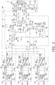
- the primary-side refrigerant circuit 5a and the secondary-side refrigerant circuit 10 of the refrigeration cycle apparatus 1 are configured as illustrated in FIG. 3 .
- arrows attached to the primary-side refrigerant circuit 5a and arrows attached to the secondary-side refrigerant circuit 10 in FIG. 3 indicate flows of the refrigerant during the cooling operation.
- the primary-side switching mechanism 72 is switched to the fifth connection state to cause the cascade heat exchanger 35 to function as an evaporator for the primary-side refrigerant.
- the fifth connection state of the primary-side switching mechanism 72 is depicted by solid lines in the primary-side switching mechanism 72 in FIG. 3 . Accordingly, in the primary-side unit 5, the primary-side refrigerant discharged from the primary-side compressor 71 passes through the primary-side switching mechanism 72 and exchanges heat with outdoor air supplied from the primary-side fan 75 in the primary-side heat exchanger 74 to be condensed.
- the primary-side refrigerant condensed in the primary-side heat exchanger 74 passes through the primary-side first expansion valve 76 controlled into a fully opened state, and a part of the refrigerant flows toward the first liquid shutoff valve 108 through the primary-side subcooling heat exchanger 103, and another part of the refrigerant branches into the primary-side subcooling circuit 104.
- the refrigerant flowing in the primary-side subcooling circuit 104 is decompressed when passing through the primary-side subcooling expansion valve 104a.
- the refrigerant flowing from the primary-side first expansion valve 76 toward the first liquid shutoff valve 108 exchanges heat with the refrigerant decompressed by the primary-side subcooling expansion valve 104a and flowing in the primary-side subcooling circuit 104 in the primary-side subcooling heat exchanger 103, and is cooled until reaching a subcooled state.
- the refrigerant in the subcooled state flows through the primary-side first connection pipe 111, the second liquid shutoff valve 106, and the second refrigerant pipe 114 in that order, and is decompressed when passing through the primary-side second expansion valve 102.
- a valve opening degree of the primary-side second expansion valve 102 is controlled such that a degree of superheating of the primary-side refrigerant sucked into the primary-side compressor 71 satisfies a predetermined condition.
- the primary-side refrigerant decompressed by the primary-side second expansion valve 102 evaporates by exchanging heat with the secondary-side refrigerant flowing through the secondary-side flow path 35a, and flows toward the second gas shutoff valve 107 through the first refrigerant pipe 113.
- the refrigerant having passed through the second gas shutoff valve 107 passes through the primary-side second connection pipe 112 and the first gas shutoff valve 109, and then reaches the primary-side switching mechanism 72.
- the refrigerant having passed through the primary-side switching mechanism 72 joins the refrigerant having flowed through the primary-side subcooling circuit 104, and is then sucked into the primary-side compressor 71 via the primary-side accumulator 105.
- the cascade heat exchanger 35 functions as a radiator for the secondary-side refrigerant.
- the discharge flow path 24 and the third pipe 25 are connected by the first switching valve 22a
- the first pipe 28 and the suction flow path 23 are connected by the second switching valve 22b.
- the second regulating valves 67a, 67b, 67c are controlled to the opened state. Accordingly, all of the utilization-side heat exchangers 52a, 52b, and 52c in the utilization units 3a, 3b, and 3c function as refrigerant evaporators.
- All of the utilization-side heat exchangers 52a, 52b, and 52c of the utilization units 3a, 3b, and 3c and the suction side of the secondary-side compressor 21 of the cascade unit 2 are connected via the first utilization pipes 57a, 57b, and 57c, the first connecting tubes 15a, 15b, and 15c, the junction pipes 62a, 62b, and 62c, the second branch pipes 64a, 64b, and 64c, the bypass pipes 69a, 69b, and 69c, a part of the first branch pipes 63a, 63b, and 63c, the secondary-side first connection pipe 8, and the secondary-side second connection pipe 9.
- an opening degree of the secondary-side subcooling expansion valve 48a is controlled such that a degree of subcooling of the secondary-side refrigerant flowing through the outlet of the secondary-side subcooling heat exchanger 47 toward the secondary-side third connection pipe 7 satisfies a predetermined condition.
- the bypass expansion valve 46a is controlled to the closed state.
- the opening degrees of the utilization-side expansion valves 51a, 51b, and 51c are adjusted.
- the secondary-side refrigerant circuit 10 controls capacity, for example, by controlling a frequency of the secondary-side compressor 21 so that evaporation temperature of the secondary-side refrigerant in the utilization-side heat exchangers 52a, 52b, and 52c becomes a predetermined secondary-side evaporation target temperature.
- the opening degree of the cascade expansion valve 36 is adjusted such that the secondary-side refrigerant flowing in the cascade heat exchanger 35 has a critical pressure or less.
- the primary-side refrigerant circuit 5a controls capacity, for example, by controlling a frequency of the primary-side compressor 71 such that evaporation temperature of the primary-side refrigerant in the primary-side flow path 35b of the cascade heat exchanger 35 becomes a predetermined primary-side evaporation target temperature.
- a frequency of the primary-side compressor 71 such that evaporation temperature of the primary-side refrigerant in the primary-side flow path 35b of the cascade heat exchanger 35 becomes a predetermined primary-side evaporation target temperature.
- a secondary-side high-pressure refrigerant compressed and discharged by the secondary-side compressor 21 is sent to the secondary-side flow path 35a of the cascade heat exchanger 35 through the first switching valve 22a of the secondary-side switching mechanism 22.
- the secondary-side high-pressure refrigerant flowing in the secondary-side flow path 35a of the cascade heat exchanger 35 radiates heat, and the primary-side refrigerant flowing in the primary-side flow path 35b of the cascade heat exchanger 35 is evaporated.
- the secondary-side refrigerant having radiated heat in the cascade heat exchanger 35 passes through the cascade expansion valve 36 whose opening degree is adjusted, and then flows into the secondary-side receiver 45.
- a part of the refrigerant flowing out of the secondary-side receiver 45 branches and flows into the secondary-side subcooling circuit 48, is decompressed in the secondary-side subcooling expansion valve 48a, and then joins the suction flow path 23.
- the secondary-side subcooling heat exchanger 47 another part of the refrigerant having flowed out of the secondary-side receiver 45 is cooled by the refrigerant flowing in the secondary-side subcooling circuit 48, and is then sent to the secondary-side third connection pipe 7 through the third shutoff valve 31.
- the refrigerant sent to the secondary-side third connection pipe 7 is branched into three portions to pass through the third branch pipes 61a, 61b, and 61c of the first to third branch units 6a, 6b, and 6c. Thereafter, the refrigerant having flowed through the second connecting tubes 16a, 16b, and 16c is sent to the second utilization pipes 56a, 56b, and 56c of the first to third utilization units 3a, 3b, and 3c.
- the refrigerant sent to the second utilization pipes 56a, 56b, and 56c is sent to the utilization-side expansion valves 51a, 51b, and 51c in the utilization units 3a, 3b, and 3c.
- the refrigerant having passed through the utilization-side expansion valves 51a, 51b, and 51c whose opening degrees are adjusted exchanges heat with indoor air supplied by the indoor fans 53a, 53b, and 53c in the utilization-side heat exchangers 52a, 52b, and 52c.
- the refrigerant flowing in the utilization-side heat exchangers 52a, 52b, and 52c is thus evaporated into a low-pressure gas refrigerant.
- the indoor air is cooled and is supplied into the indoor space. The indoor space is thus cooled.
- the low-pressure gas refrigerant sent to the junction pipes 62a, 62b, and 62c flows to the second branch pipes 64a, 64b, and 64c.
- a part of the refrigerant that has passed through the second regulating valves 67a, 67b, and 67c in the second branch pipes 64a, 64b, and 64c is sent to the secondary-side second connection pipe 9.
- the remaining part of the refrigerant that has passed through the second regulating valves 67a, 67b, and 67c passes through the bypass pipes 69a, 69b, and 69c, flows through a part of the first branch pipes 63a, 63b, and 63c, and then is sent to the secondary-side first connection pipe 8.
- the low-pressure gas refrigerant sent to the secondary-side first connection pipe 8 and the secondary-side second connection pipe 9 is returned to the suction side of the secondary-side compressor 21 through the first shutoff valve 32, the second shutoff valve 33, the first pipe 28, the second pipe 29, the second switching valve 22b of the secondary-side switching mechanism 22, the suction flow path 23, and the secondary-side accumulator 30.
- Motion during the cooling operation is performed in such a manner.
- each of the utilization-side heat exchangers 52a, 52b, and 52c in the utilization units 3a, 3b, and 3c functions as a refrigerant radiator.
- the cascade heat exchanger 35 operates to function as an evaporator for the secondary-side refrigerant.
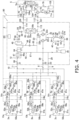
- the primary-side refrigerant circuit 5a and the secondary-side refrigerant circuit 10 of the refrigeration cycle apparatus 1 are configured as illustrated in FIG. 4 .
- Arrows attached to the primary-side refrigerant circuit 5a and arrows attached to the secondary-side refrigerant circuit 10 in FIG. 4 indicate flows of the refrigerant during the heating operation.
- the primary-side switching mechanism 72 is switched to a sixth operating state to cause the cascade heat exchanger 35 to function as a radiator for the primary-side refrigerant.
- the sixth operating state of the primary-side switching mechanism 72 is a connection state depicted by broken lines in the primary-side switching mechanism 72 in FIG. 4 . Accordingly, in the primary-side unit 5, the primary-side refrigerant discharged from the primary-side compressor 71, having passed through the primary-side switching mechanism 72 and the first gas shutoff valve 109 passes through the primary-side second connection pipe 112 and the second gas shutoff valve 107 and is sent to the primary-side flow path 35b of the cascade heat exchanger 35.
- the refrigerant flowing in the primary-side flow path 35b of the cascade heat exchanger 35 is condensed by exchanging heat with the secondary-side refrigerant flowing in the secondary-side flow path 35a.
- the primary-side refrigerant condensed in the cascade heat exchanger 35 passes through the primary-side second expansion valve 102 controlled to the fully opened state.
- the refrigerant that has passed through the primary-side second expansion valve 102 flows through the second liquid shutoff valve 106, the primary-side first connection pipe 111, the first liquid shutoff valve 108, and the primary-side subcooling heat exchanger 103 in that order, and is decompressed by the primary-side first expansion valve 76.
- the primary-side subcooling expansion valve 104a is controlled to the closed state. Accordingly, the refrigerant does not flow to the primary-side subcooling circuit 104 and does not exchange heat in the primary-side subcooling heat exchanger 103.
- the valve opening degree of the primary-side first expansion valve 76 is controlled such that, for example, the degree of superheating of the refrigerant sucked into the primary-side compressor 71 satisfies a predetermined condition.
- the refrigerant decompressed by the primary-side first expansion valve 76 evaporates by exchanging heat with outdoor air supplied from the primary-side fan 75 in the primary-side heat exchanger 74, passes through the primary-side switching mechanism 72 and the primary-side accumulator 105, and is sucked into the primary-side compressor 71.
- the secondary-side switching mechanism 22 is switched to the second connection state.
- the cascade heat exchanger 35 thus functions as an evaporator for the secondary-side refrigerant.
- the discharge flow path 24 and the first pipe 28 are connected by the second switching valve 22b, and the third pipe 25 and the suction flow path 23 are connected by the first switching valve 22a.
- the opening degree of the cascade expansion valve 36 is adjusted.
- the first regulating valves 66a, 66b, and 66c are controlled to the opened state
- the second regulating valves 67a, 67b, and 67c are controlled to the closed state.
- all of the utilization-side heat exchangers 52a, 52b, and 52c in the utilization units 3a, 3b, and 3c function as refrigerant radiators.
- the utilization-side heat exchangers 52a, 52b, and 52c in the utilization units 3a, 3b, and 3c and the discharge side of the secondary-side compressor 21 in the cascade unit 2 are connected via the discharge flow path 24, the first pipe 28, the secondary-side first connection pipe 8, the first branch pipes 63a, 63b, and 63c, the junction pipes 62a, 62b, and 62c, the first connecting tubes 15a, 15b, and 15c, and the first utilization pipes 57a, 57b, and 57c.
- the secondary-side subcooling expansion valve 48a and the bypass expansion valve 46a are controlled to the closed state.
- the opening degrees of the utilization-side expansion valves 51a, 51b, and 51c are adjusted.
- the secondary-side refrigerant circuit 10 controls capacity on the secondary-side compressor 21 so as to achieve a frequency at which the loads in the utilization-side heat exchangers 52a, 52b, and 52c can be processed.
- the secondary-side refrigerant discharged from the secondary-side compressor 21 is controlled to be in a critical state exceeding the critical pressure.
- the primary-side refrigerant circuit 5a controls capacity, for example, by controlling the frequency of the primary-side compressor 71 such that condensation temperature of the primary-side refrigerant in the primary-side flow path 35b of the cascade heat exchanger 35 becomes a predetermined primary-side condensation target temperature.
- the high-pressure refrigerant compressed and discharged by the secondary-side compressor 21 is sent to the first pipe 28 through the second switching valve 22b of the secondary-side switching mechanism 22.
- the refrigerant sent to the first pipe 28 is sent to the secondary-side first connection pipe 8 through the first shutoff valve 32.
- the high-pressure refrigerant sent to the secondary-side first connection pipe 8 is branched into three portions to be sent to the first branch pipes 63a, 63b, and 63c in the utilization units 3a, 3b, and 3c which are utilization units in operation.
- the high-pressure refrigerant sent to the first branch pipes 63a, 63b, and 63c passes through the first regulating valves 66a, 66b, and 66c, and flows in the junction pipes 62a, 62b, and 62c.
- the refrigerant having flowed in the first connecting tubes 15a, 15b, and 15c and the first utilization pipes 57a, 57b, and 57c is sent to the utilization-side heat exchangers 52a, 52b, and 52c.
- the high-pressure refrigerant sent to the utilization-side heat exchangers 52a, 52b, and 52c exchanges heat with indoor air supplied by the indoor fans 53a, 53b, and 53c in the utilization-side heat exchangers 52a, 52b, and 52c.
- the refrigerant flowing in the utilization-side heat exchangers 52a, 52b, and 52c thus radiates heat.
- the indoor air is heated and supplied into the indoor space.
- the indoor space is thus heated.
- the refrigerant having radiated heat in the utilization-side heat exchangers 52a, 52b, and 52c flows in the second utilization pipes 56a, 56b, and 56c and passes through the utilization-side expansion valves 51a, 51b, and 51c whose opening degrees are adjusted.
- the secondary-side refrigerant that has passed through the utilization-side expansion valves 51a, 51b, and 51c has the critical pressure or less. Thereafter, the refrigerant having flowed through the second connecting tubes 16a, 16b, and 16c flows in the third branch pipes 61a, 61b, and 61c of the branch units 6a, 6b, and 6c.
- the refrigerant sent to the third branch pipes 61a, 61b, and 61c is sent to the secondary-side third connection pipe 7 to join.
- the refrigerant sent to the secondary-side third connection pipe 7 passes through the third shutoff valve 31 and then is sent to the cascade expansion valve 36.
- the flow rate of the refrigerant sent to the cascade expansion valve 36 is adjusted at the cascade expansion valve 36, and then, the refrigerant is sent to the cascade heat exchanger 35.
- the secondary-side refrigerant flowing in the secondary-side flow path 35a is evaporated into a low-pressure gas refrigerant and is sent to the secondary-side switching mechanism 22, and the primary-side refrigerant flowing in the primary-side flow path 35b of the cascade heat exchanger 35 is condensed.
- the secondary-side low-pressure gas refrigerant sent to the first switching valve 22a of the secondary-side switching mechanism 22 is returned to the suction side of the secondary-side compressor 21 through the suction flow path 23 and the secondary-side accumulator 30.
- Motion during the heating operation is performed in such a manner.
- the utilization-side heat exchangers 52a and 52b in the utilization units 3a and 3b function as refrigerant evaporators, and the utilization-side heat exchanger 52c in the utilization unit 3c functions as a refrigerant radiator.
- the cascade heat exchanger 35 functions as a radiator for the secondary-side refrigerant.
- the primary-side refrigerant circuit 5a and the secondary-side refrigerant circuit 10 of the refrigeration cycle apparatus 1 are configured as illustrated in FIG. 5 . Arrows attached to the primary-side refrigerant circuit 5a and arrows attached to the secondary-side refrigerant circuit 10 in FIG. 5 indicate flows of the refrigerant during the cooling main operation.
- the primary-side switching mechanism 72 is switched to the fifth connection state (the state depicted by solid lines in the primary-side switching mechanism 72 in FIG. 5 ) to cause the cascade heat exchanger 35 to function as an evaporator for the primary-side refrigerant. Accordingly, in the primary-side unit 5, the primary-side refrigerant discharged from the primary-side compressor 71 passes through the primary-side switching mechanism 72 and exchanges heat with outdoor air supplied from the primary-side fan 75 in the primary-side heat exchanger 74 to be condensed.
- the primary-side refrigerant condensed in the primary-side heat exchanger 74 passes through the primary-side first expansion valve 76 controlled into a fully opened state, and a part of the refrigerant flows toward the first liquid shutoff valve 108 through the primary-side subcooling heat exchanger 103, and another part of the refrigerant branches into the primary-side subcooling circuit 104.
- the refrigerant flowing in the primary-side subcooling circuit 104 is decompressed when passing through the primary-side subcooling expansion valve 104a.
- the refrigerant flowing from the primary-side first expansion valve 76 toward the first liquid shutoff valve 108 exchanges heat with the refrigerant decompressed by the primary-side subcooling expansion valve 104a and flowing in the primary-side subcooling circuit 104 in the primary-side subcooling heat exchanger 103, and is cooled until reaching a subcooled state.
- the refrigerant in the subcooled state flows through the primary-side first connection pipe 111, the second liquid shutoff valve 106, and the second refrigerant pipe 114 in that order, and is decompressed by the primary-side second expansion valve 102.
- a valve opening degree of the primary-side second expansion valve 102 is controlled such that the degree of superheating of the refrigerant sucked into the primary-side compressor 71 satisfies a predetermined condition.
- the primary-side refrigerant decompressed by the primary-side second expansion valve 102 evaporates by exchanging heat with the secondary-side refrigerant flowing through the secondary-side flow path 35a, and flows toward the second gas shutoff valve 107 through the first refrigerant pipe 113.
- the refrigerant having passed through the second gas shutoff valve 107 passes through the primary-side second connection pipe 112 and the first gas shutoff valve 109, and then reaches the primary-side switching mechanism 72.
- the refrigerant having passed through the primary-side switching mechanism 72 joins the refrigerant having flowed through the primary-side subcooling circuit 104, and is then sucked into the primary-side compressor 71 via the primary-side accumulator 105.
- the secondary-side switching mechanism 22 is switched to the third connection state in which the discharge flow path 24 and the third pipe 25 are connected by the first switching valve 22a and the discharge flow path 24 and the first pipe 28 are connected by the second switching valve 22b to cause the cascade heat exchanger 35 to function as a radiator for the secondary-side refrigerant.
- the opening degree of the cascade expansion valve 36 is adjusted.
- the first regulating valve 66c and the second regulating valves 67a and 67b are controlled to the opened state
- the first regulating valves 66a and 66b and the second regulating valve 67c are controlled to the closed state.
- the utilization-side heat exchangers 52a and 52b in the utilization units 3a and 3b function as refrigerant evaporators
- the utilization-side heat exchanger 52c in the utilization unit 3c functions as a refrigerant radiator.
- the utilization-side heat exchangers 52a and 52b in the utilization units 3a and 3b and the suction side of the secondary-side compressor 21 in the cascade unit 2 are connected via the secondary-side second connection pipe 9, and the utilization-side heat exchanger 52c in the utilization unit 3c and the discharge side of the secondary-side compressor 21 in the cascade unit 2 are connected via the secondary-side first connection pipe 8.
- an opening degree of the secondary-side subcooling expansion valve 48a is controlled such that a degree of subcooling of the secondary-side refrigerant flowing through the outlet of the secondary-side subcooling heat exchanger 47 toward the secondary-side third connection pipe 7 satisfies a predetermined condition.
- the bypass expansion valve 46a is controlled to the closed state.
- the opening degrees of the utilization-side expansion valves 51a, 51b, and 51c are adjusted.
- the secondary-side refrigerant circuit 10 controls capacity, for example, by controlling the frequency of the secondary-side compressor 21 such that evaporation temperature in a heat exchanger functioning as an evaporator for the secondary-side refrigerant among the utilization-side heat exchanger 52a, 52b, and 52c becomes a predetermined secondary-side evaporation target temperature.
- the opening degree of the cascade expansion valve 36 is adjusted such that the secondary-side refrigerant flowing in the cascade heat exchanger 35 has a critical pressure or less.
- the primary-side refrigerant circuit 5a controls capacity, for example, by controlling a frequency of the primary-side compressor 71 such that evaporation temperature of the primary-side refrigerant in the primary-side flow path 35b of the cascade heat exchanger 35 becomes a predetermined primary-side evaporation target temperature.
- a frequency of the primary-side compressor 71 such that evaporation temperature of the primary-side refrigerant in the primary-side flow path 35b of the cascade heat exchanger 35 becomes a predetermined primary-side evaporation target temperature.
- a part of the secondary-side high-pressure refrigerant compressed and discharged by the secondary-side compressor 21 is sent to the secondary-side first connection pipe 8 through the second switching valve 22b of the secondary-side switching mechanism 22, the first pipe 28, and the first shutoff valve 32, and the rest is sent to the secondary-side flow path 35a of the cascade heat exchanger 35 through the first switching valve 22a of the secondary-side switching mechanism 22 and the third pipe 25.
- the high-pressure refrigerant sent to the secondary-side first connection pipe 8 is sent to the first branch pipe 63c.
- the high-pressure refrigerant sent to the first branch pipe 63c is sent to the utilization-side heat exchanger 52c in the utilization unit 3c through the first regulating valve 66c and the junction pipe 62c.
- the high-pressure refrigerant sent to the utilization-side heat exchanger 52c exchanges heat with indoor air supplied by the indoor fan 53c in the utilization-side heat exchanger 52c.
- the refrigerant flowing in the utilization-side heat exchanger 52c thus radiates heat.
- the indoor air is heated and is supplied into the indoor space, and the utilization unit 3c performs the heating operation.
- the refrigerant having radiated heat in the utilization-side heat exchanger 52c flows in the second utilization pipe 56c, and the flow rate of the refrigerant is adjusted at the utilization-side expansion valve 51c.
- the refrigerant having flowed through the second connecting tube 16c is sent to the third branch pipe 61c in the branch unit 6c.
- the high-pressure refrigerant sent to the secondary-side flow path 35a of the cascade heat exchanger 35 exchanges heat with the primary-side refrigerant flowing in the primary-side flow path 35b in the cascade heat exchanger 35 to radiate heat.
- the flow rate of the secondary-side refrigerant having radiated heat in the cascade heat exchanger 35 is adjusted at the cascade expansion valve 36, and then the secondary-side refrigerant flows into the secondary-side receiver 45.
- a part of the refrigerant having flowed out of the secondary-side receiver 45 branches into the secondary-side subcooling circuit 48, is decompressed at the secondary-side subcooling expansion valve 48a, and then joins into the suction flow path 23.
- the secondary-side subcooling heat exchanger 47 another part of the refrigerant having flowed out of the secondary-side receiver 45 is cooled by the refrigerant flowing in the secondary-side subcooling circuit 48, is then sent to the secondary-side third connection pipe 7 through the third shutoff valve 31, and joins the refrigerant having radiated heat in the utilization-side heat exchanger 52c.
- the refrigerant having joined in the secondary-side third connection pipe 7 is branched into two portions to be sent to the third branch pipes 61a and 61b of the branch units 6a and 6b. Thereafter, the refrigerant having flowed in the second connecting tubes 16a and 16b is sent to the second utilization pipes 56a and 56b of the first and second utilization units 3a and 3b.
- the refrigerant flowing in the second utilization pipes 56a and 56b passes through the utilization-side expansion valves 51a and 51b in the utilization units 3a and 3b.
- the refrigerant flowing in the utilization-side heat exchangers 52a and 52b is thus evaporated into a low-pressure gas refrigerant.
- the indoor air is cooled and is supplied into the indoor space.
- the indoor space is thus cooled.
- the low-pressure gas refrigerant evaporated in the utilization-side heat exchangers 52a and 52b is sent to the junction pipes 62a and 62b of the first and second branch units 6a and 6b.
- the low-pressure gas refrigerant sent to the junction pipes 62a and 62b is sent to the secondary-side second connection pipe 9 via the second regulating valves 67a and 67b and the second branch pipes 64a and 64b, to join.
- the low-pressure gas refrigerant sent to the secondary-side second connection pipe 9 is returned to the suction side of the secondary-side compressor 21 via the second shutoff valve 33, the second pipe 29, the suction flow path 23, and the secondary-side accumulator 30.
- Motion during the cooling main operation is performed in such a manner.
- the utilization-side heat exchangers 52a and 52b in the utilization units 3a and 3b function as refrigerant radiators, and the utilization-side heat exchanger 52c functions as a refrigerant evaporator.
- the cascade heat exchanger 35 functions as an evaporator for the secondary-side refrigerant.
- the primary-side refrigerant circuit 5a and the secondary-side refrigerant circuit 10 of the refrigeration cycle apparatus 1 are configured as illustrated in FIG. 6 . Arrows attached to the primary-side refrigerant circuit 5a and arrows attached to the secondary-side refrigerant circuit 10 in FIG. 6 indicate flows of the refrigerant during the heating main operation.
- the primary-side switching mechanism 72 is switched to a sixth operating state to cause the cascade heat exchanger 35 to function as a radiator for the primary-side refrigerant.
- the sixth operating state of the primary-side switching mechanism 72 corresponds to a connection state depicted by broken lines in the primary-side switching mechanism 72 in FIG. 6 . Accordingly, in the primary-side unit 5, the primary-side refrigerant discharged from the primary-side compressor 71, having passed through the primary-side switching mechanism 72 and the first gas shutoff valve 109 passes through the primary-side second connection pipe 112 and the second gas shutoff valve 107 and is sent to the primary-side flow path 35b of the cascade heat exchanger 35.
- the refrigerant flowing in the primary-side flow path 35b of the cascade heat exchanger 35 is condensed by exchanging heat with the secondary-side refrigerant flowing in the secondary-side flow path 35a.
- the primary-side refrigerant condensed in the cascade heat exchanger 35 passes through the primary-side second expansion valve 102 controlled to the fully opened state. Then, the primary-side refrigerant flows through the second liquid shutoff valve 106, the primary-side first connection pipe 111, the first liquid shutoff valve 108, and the primary-side subcooling heat exchanger 103 in that order, and is decompressed by the primary-side first expansion valve 76.
- the primary-side subcooling expansion valve 104a is controlled to the closed state. Accordingly, the refrigerant does not flow into the primary-side subcooling circuit 104 and does not exchange heat in the primary-side subcooling heat exchanger 103.
- the valve opening degree of the primary-side first expansion valve 76 is controlled such that, for example, the degree of superheating of the refrigerant sucked into the primary-side compressor 71 satisfies a predetermined condition.
- the refrigerant decompressed by the primary-side first expansion valve 76 evaporates by exchanging heat with outdoor air supplied from the primary-side fan 75 in the primary-side heat exchanger 74, passes through the primary-side switching mechanism 72 and the primary-side accumulator 105, and is sucked into the primary-side compressor 71.
- the secondary-side switching mechanism 22 is switched to the second connection state.
- the discharge flow path 24 and the first pipe 28 are connected by the second switching valve 22b
- the third pipe 25 and the suction flow path 23 are connected by the first switching valve 22a.
- the cascade heat exchanger 35 thus functions as an evaporator for the secondary-side refrigerant.
- the opening degree of the cascade expansion valve 36 is adjusted.
- the first regulating valves 66a and 66b and the second regulating valve 67c are controlled to the opened state
- the first regulating valve 66c and the second regulating valves 67a and 67b are controlled to the closed state.
- the utilization-side heat exchangers 52a and 52b in the utilization units 3a and 3b function as refrigerant radiators
- the utilization-side heat exchanger 52c in the utilization unit 3c functions as a refrigerant evaporator.
- the utilization-side heat exchanger 52c in the utilization unit 3c and the suction side of the secondary-side compressor 21 in the cascade unit 2 are connected via the first utilization pipe 57c, the first connecting tube 15c, the junction pipe 62c, the second branch pipe 64c, and the secondary-side second connection pipe 9.
- the utilization-side heat exchangers 52a and 52b in the utilization units 3a and 3b and the discharge side of the secondary-side compressor 21 in the cascade unit 2 are connected via the discharge flow path 24, the first pipe 28, the secondary-side first connection pipe 8, the first branch pipes 63a and 63b, the junction pipes 62a and 62b, the first connecting tubes 15a and 15b, and the first utilization pipes 57a and 57b.
- the secondary-side subcooling expansion valve 48a and the bypass expansion valve 46a are controlled to the closed state.
- the opening degrees of the utilization-side expansion valves 51a, 51b, and 51c are adjusted.
- the secondary-side refrigerant circuit 10 controls capacity, for example, by controlling the frequency of the secondary-side compressor 21 so as to process a load in a heat exchanger functioning as a radiator for the secondary-side refrigerant among the utilization-side heat exchangers 52a, 52b, and 52c.
- the secondary-side refrigerant discharged from the secondary-side compressor 21 is controlled to be in the critical state exceeding the critical pressure.
- the primary-side refrigerant circuit 5a controls capacity, for example, by controlling the frequency of the primary-side compressor 71 such that condensation temperature of the primary-side refrigerant in the primary-side flow path 35b of the cascade heat exchanger 35 becomes a predetermined primary-side condensation target temperature.
- the secondary-side high-pressure refrigerant compressed and discharged by the secondary-side compressor 21 is sent to the secondary-side first connection pipe 8 through the second switching valve 22b of the secondary-side switching mechanism 22, the first pipe 28, and the first shutoff valve 32.
- the high-pressure refrigerant sent to the secondary-side first connection pipe 8 is branched into two portions to be sent to the first branch pipes 63a and 63b of the first branch unit 6a and the second branch unit 6b respectively connected to the first utilization unit 3a and the second utilization unit 3b which are utilization units in operation.
- the high-pressure refrigerant sent to the first branch pipes 63a and 63b is sent to the utilization-side heat exchangers 52a and 52b in the first utilization unit 3a and the second utilization unit 3b via the first regulating valves 66a and 66b, the junction pipes 62a and 62b, and the first connecting tubes 15a and 15b.
- the high-pressure refrigerant sent to the utilization-side heat exchangers 52a and 52b exchanges heat with indoor air supplied by the indoor fans 53a and 53b in the utilization-side heat exchangers 52a and 52b.
- the refrigerant flowing in the utilization-side heat exchangers 52a and 52b thus radiates heat.
- the indoor air is heated and supplied into the indoor space.
- the indoor space is thus heated.
- the refrigerant having radiated heat in the utilization-side heat exchangers 52a and 52b flows in the second utilization pipes 56a and 56b, and passes through the utilization-side expansion valves 51a and 51b whose opening degree is adjusted.
- the secondary-side refrigerant that has passed through the utilization-side expansion valves 51a and 51b has the critical pressure or less. Thereafter, the refrigerant having flowed through the second connecting tubes 16a and 16b is sent to the secondary-side third connection pipe 7 via the third branch pipes 61a and 61b of the branch units 6a and 6b.
- a part of the refrigerant sent to the secondary-side third connection pipe 7 is sent to the third branch pipe 61c of the branch unit 6c, and the rest flows toward the third shutoff valve 31.
- the refrigerant sent to the third branch pipe 61c flows in the second utilization pipe 56c of the utilization unit 3c via the second connecting tube 16c, and is sent to the utilization-side expansion valve 51c.
- the refrigerant having passed through the utilization-side expansion valve 51c whose opening degree is adjusted exchanges heat with indoor air supplied by the indoor fan 53c in the utilization-side heat exchanger 52c.
- the refrigerant flowing in the utilization-side heat exchanger 52c is thus evaporated into a low-pressure gas refrigerant.
- the indoor air is cooled and is supplied into the indoor space.
- the indoor space is thus cooled.
- the low-pressure gas refrigerant evaporated in the utilization-side heat exchanger 52c passes through the first utilization pipe 57c and the first connecting tube 15c to be sent to the junction pipe 62c.
- the low-pressure gas refrigerant sent to the junction pipe 62c is sent to the secondary-side second connection pipe 9 through the second regulating valve 67c and the second branch pipe 64c.
- the low-pressure gas refrigerant sent to the secondary-side second connection pipe 9 is returned to the suction side of the secondary-side compressor 21 via the second shutoff valve 33, the second pipe 29, the suction flow path 23, and the secondary-side accumulator 30.
- the refrigerant flowing toward the third shutoff valve 31 is sent to the cascade expansion valve 36.
- the refrigerant sent to the cascade expansion valve 36 passes through the cascade expansion valve 36 whose opening degree is adjusted, and then exchanges heat with the primary-side refrigerant flowing in the primary-side flow path 35b in the secondary-side flow path 35a of the cascade heat exchanger 35.
- the refrigerant flowing in the secondary-side flow path 35a of the cascade heat exchanger 35 evaporates to become a low-pressure gas refrigerant, and is sent to the first switching valve 22a of the secondary-side switching mechanism 22.
- the low-pressure gas refrigerant sent to the first switching valve 22a of the secondary-side switching mechanism 22 joins the low-pressure gas refrigerant evaporated in the utilization-side heat exchanger 52c in the suction flow path 23.
- the refrigerant thus joined is returned to the suction side of the secondary-side compressor 21 via the secondary-side accumulator 30.
- Motion during the heating main operation is performed in such a manner.
- FIG. 7 is a schematic configuration diagram of the secondary-side receiver 45, the flow path switching portion 96, the first safety valve 91, and the second safety valve 92.
- FIG. 8 is a schematic explanatory diagram illustrating a state where the first safety valve 91 is detached.
- the secondary-side receiver 45 includes iron or an iron alloy such as carbon steel.
- the content of carbon is 0.04 wt% or more and 2 wt% or less.
- the secondary-side receiver 45 includes a vessel body 45x, a first connection portion 45a, a second connection portion 45b, a third connection portion 45c, and a fourth connection portion 45d.
- the vessel body 45x is a substantially cylindrical vessel having an internal volume corresponding to the amount of refrigerant filled in the secondary-side refrigerant circuit 10, and temporarily reserves the refrigerant flowing in the secondary-side refrigerant circuit 10.
- the first connection portion 45a is a pipe extending laterally from a part of a peripheral surface of the vessel body 45x, and is connected to a third connecting portion 99a of the flow path switching portion 96.
- the second connection portion 45b is a pipe extending laterally from a part of a peripheral surface of the vessel body 45x, and constitutes a part of the fourth pipe 26 in the secondary-side refrigerant circuit 10.
- the third connection portion 45c is a pipe extending laterally from a part of a peripheral surface of the vessel body 45x, and constitutes a part of the bypass circuit 46 in the secondary-side refrigerant circuit 10.
- the fourth connection portion 45d is a pipe extending downward from a bottom of the vessel body 45x, and constitutes a part of the fifth pipe 27 in the secondary-side refrigerant circuit 10.
- An end of the third connection portion 45c in the vessel body 45x is positioned above an end of the second connection portion 45b in the vessel body 45x and an end of the fourth connection portion 45d in the vessel body 45x.
- connection point and a direction of the connection of the first connection portion 45a, the second connection portion 45b, the third connection portion 45c, and the fourth connection portion 45d to the vessel body 45x are not limitation on a connection point and a direction of the connection of the first connection portion 45a, the second connection portion 45b, the third connection portion 45c, and the fourth connection portion 45d to the vessel body 45x.
- the flow path switching portion 96 is made of stainless steel.
- Stainless steel is an alloy containing iron as a main component, a chromium content of 10.5 wt% or more, and a carbon content of 1.2 wt% or less (the same applies hereinafter).
- Examples of the stainless steel include SUS304, SUS316, SUS303, SUS410, and SUS430, and among the above, any one of SUS304TP, SUS304HTP, SUS304LTP, or SUS316LTP is preferable.
- the flow path switching portion 96 includes a flow path switching valve 99, the third connecting portion 99a, a first connecting pipe 97, and a second connecting pipe 98.
- the first connecting pipe 97 extends from one of the connection ports of the flow path switching valve 99, and has a first connecting portion 97a at an end of the first connecting pipe 97.
- the first safety valve connecting portion 91a of the first safety valve 91 is connected to the first connecting portion 97a of the first connecting pipe 97.
- the first connecting portion 97a is provided with a screw groove 97x corresponding to a screw thread 91x of the first safety valve connecting portion 91a of the first safety valve 91 described later. Accordingly, the first safety valve 91 is screwed and connected to the first connecting portion 97a.
- the second connecting pipe 98 extends from one of the connection ports of the flow path switching valve 99, and has a second connecting portion 98a at an end of the second connecting pipe 98.
- the second safety valve connecting portion 92a of the second safety valve 92 is connected to the second connecting portion 98a of the second connecting pipe 98.
- the second connecting portion 98a is provided with a screw groove corresponding to a screw thread (not illustrated) of the second safety valve connecting portion 92a of the second safety valve 92 described later. Accordingly, the second safety valve 92 is screwed and connected to the second connecting portion 98a.
- the third connecting portion 99a connects one of the connection ports of the flow path switching valve 99 and the first connection portion 45a of the secondary-side receiver 45. Note that the flow path switching valve 99, the third connecting portion 99a, and the first connection portion 45a are connected to each other by welding, for example.
- the flow path switching valve 99 includes a plurality of connection ports, and is a switching valve that switches between a state in which the third connecting portion 99a and the first connecting portion 97a are connected and a state in which the third connecting portion 99a and the second connecting portion 98a are connected.
- the flow path switching valve 99 is, for example, a manual valve.
- the flow path switching valve 99 may include, for example, a three-way valve, or may include three connection ports of a four-way valve.
- Each of the first safety valve 91 and the second safety valve 92 functions in a state of communicating with the secondary-side receiver 45, and can automatically release the secondary-side refrigerant to the outside when the pressure of the secondary-side refrigerant in the secondary-side receiver 45 becomes a predetermined value or more.
- a safety valve is also referred to as a pressure relief valve, and includes, for example, a pressure relief valve. As a result, an abnormal increase in the pressure of the secondary-side refrigerant in the secondary-side receiver 45 is suppressed.
- a safety valve for example, any of a weight safety valve, a lever safety valve, a spring safety valve, or the like can be used.
- the safety valve is detached at a predetermined frequency such as once a year to confirm that the safety valve functions appropriately. As this confirmation work, for example, when the safety valve is a spring safety valve, whether the spring functions appropriately is confirmed.
- the first safety valve 91 is made of stainless steel.
- the first safety valve 91 and the flow path switching portion 96 may include different types of stainless steel, but preferably include the same type of stainless steel from the viewpoint of suppressing corrosion due to a potential difference.
- the first safety valve 91 has the first safety valve connecting portion 91a for connecting to the first connecting portion 97a of the first connecting pipe 97.
- the first safety valve connecting portion 91a has the screw thread 91x corresponding to the screw groove 97x provided in the first connecting portion 97a.
- the second safety valve 92 is made of stainless steel.
- the second safety valve 92 and the flow path switching portion 96 may include different types of stainless steel, but preferably include the same type of stainless steel from the viewpoint of suppressing corrosion due to a potential difference.
- the second safety valve 92 has the second safety valve connecting portion 92a for connecting to the second connecting portion 98a of the second connecting pipe 98.
- the second safety valve connecting portion 92a has a screw thread (not illustrated) corresponding to the screw groove provided in the second connecting portion 98a.
- the flow path switching portion 96, the first safety valve 91, and the second safety valve 92 described above satisfy the following material relationship.
- the potential difference between the first connecting portion 97a of the flow path switching portion 96 and the first safety valve connecting portion 91a of the first safety valve 91 is 0.35 V or less, preferably 0.3 V or less, and more preferably 0.2 V or less.
- the potential difference between the second connecting portion 98a of the flow path switching portion 96 and the second safety valve connecting portion 92a of the second safety valve 92 is 0.35 V or less, preferably 0.3 V or less, and more preferably 0.2 V or less. Since the potential difference between connecting parts is less than 0.35 V, metal corrosion at the connection point is suppressed.
- the potential difference may be a value measured under the condition of 10°C to 27°C at the flow rate of 24 m/s to 40 m/s in seawater.
- An allowable tensile stress of the first safety valve connecting portion 91a of the first safety valve 91 with respect to an allowable tensile stress of the first connecting portion 97a of the flow path switching portion 96 (the allowable tensile stress of the first safety valve connecting portion 91a of the first safety valve 91/the allowable tensile stress of the first connecting portion 97a of the flow path switching portion 96) is 3.0 times or less, preferably 2.5 times or less, and more preferably 2.0 times or less.
- An allowable tensile stress of the second safety valve connecting portion 92a of second safety valve 92 with respect to an allowable tensile stress of the second connecting portion 98a of the flow path switching portion 96 (the allowable tensile stress of the second safety valve connecting portion 92a of the second safety valve 92/the allowable tensile stress of the second connecting portion 98a of the flow path switching portion 96) is 3.0 times or less, preferably 2.5 times or less, and more preferably 2.0 times or less.
- the allowable tensile stress of the first connecting portion 97a of the flow path switching portion 96 is not excessively smaller than the allowable tensile stress of the first safety valve connecting portion 91a of the first safety valve 91. Therefore, the screw groove 97x of the first connecting portion 97a of the flow path switching portion 96 is prevented from being crushed by repetition of attachment and detachment of the first safety valve 91.
- the value of the ratio of the allowable tensile stresses of the connecting parts is 3.0 times or less, and the allowable tensile stress of the second connecting portion 98a of the flow path switching portion 96 is not excessively smaller than the allowable tensile stress of the second safety valve connecting portion 92a of the second safety valve 92. Therefore, the screw groove of the second connecting portion 98a of the flow path switching portion 96 is prevented from being crushed by repeated attachment and detachment of the second safety valve 92.
- the allowable tensile stress may be a value at normal temperature, which is an environment where the safety valve is detached.
- the lower limit of the allowable tensile stress of the first safety valve connecting portion 91a of the first safety valve 91 with respect to the allowable tensile stress of the first connecting portion 97a of the flow path switching portion 96 is not limited, but may be, for example, 0.3 or more, preferably 0.5 or more, and may be 1.0 or more.
- the lower limit of the allowable tensile stress of the second safety valve connecting portion 92a of the second safety valve 92 with respect to the allowable tensile stress of the second connecting portion 98a of the flow path switching portion 96 is not limited, but may be, for example, 0.3 or more, preferably 0.5 or more, and may be 1.0 or more.
- the flow paths of the first safety valve 91 and the second safety valve 92 described above are switched by the flow path switching valve 99 of the flow path switching portion 96, so that the first safety valve 91 or the second safety valve 92 that communicates with the secondary-side receiver 45 functions as a safety valve.
- the operation of the refrigeration cycle apparatus 1 is stopped after being used for a predetermined period in a state where the first safety valve 91 and the secondary-side receiver 45 communicate with each other, and a state where the first safety valve 91 and the secondary-side receiver 45 communicate with each other is switched to a state where the second safety valve 92 and the secondary-side receiver 45 communicate with each other in a state where both the first safety valve 91 and the second safety valve 92 are screwed and connected to the flow path switching portion 96.
- the first safety valve 91 is detached from the flow path switching portion 96, and the first safety valve 91 can be inspected.
- the value of the ratio of the allowable tensile stress of the first safety valve connecting portion 91a of the first safety valve 91 to the allowable tensile stress of the first connecting portion 97a of the flow path switching portion 96 (the allowable tensile stress of the first safety valve connecting portion 91a/the allowable tensile stress of the first connecting portion 97a) is small. Accordingly, the screw groove 97x of the first connecting portion 97a of the flow path switching portion 96 is prevented from being crushed by repeated attachment and detachment of the first safety valve 91.
- the value of the ratio of the allowable tensile stress of the second safety valve connecting portion 92a of the second safety valve 92 to the allowable tensile stress of the second connecting portion 98a of the flow path switching portion 96 (the allowable tensile stress of the second safety valve connecting portion 92a/the allowable tensile stress of the second connecting portion 98a) is small. Accordingly, the screw groove of the second connecting portion 98a of the flow path switching portion 96 is prevented from being crushed by repeated attachment and detachment of the second safety valve 92.
- the strength is sufficiently secured, and even if the attachment and detachment of the first safety valve 91 and the second safety valve 92 are repeated, the state of each connecting portion of the first safety valve 91, the second safety valve 92, and the flow path switching portion 96 is favorably maintained.
- the carbon dioxide refrigerant is filled in the secondary-side refrigerant circuit 10.
- the carbon dioxide refrigerant is in the supercritical state, there is a possibility that the behavior of the refrigerant temperature becomes unstable.
- a safety valve that functions in accordance with the pressure of the carbon dioxide refrigerant rather than the temperature of the carbon dioxide refrigerant is used. Accordingly, the reliability of the refrigeration cycle apparatus 1 can be enhanced.
- the flow path switching portion 96 includes the first connecting pipe 97 having the first connecting portion 97a and the second connecting pipe 98 having the second connecting portion 98a.
- the flow path switching portion 96 according to another embodiment A is not required to include the first connecting pipe 97 and the second connecting pipe 98 according to the above embodiment.
- the flow path switching portion 96 according to another embodiment A may include a first connecting portion 99b instead of the first connecting portion 97a according to the above embodiment, and may include a second connecting portion 99c instead of the second connecting portion 98a.
- the first connecting portion 99b connects one of the connection ports of the flow path switching valve 99 and the first safety valve connecting portion 91a of the first safety valve 91.
- the first connecting portion 99b is provided with a screw groove corresponding to the screw thread 91x of the first safety valve connecting portion 91a of the first safety valve 91.
- the second connecting portion 99c connects one of the connection ports of the flow path switching valve 99 and the second safety valve connecting portion 92a of the second safety valve 92.
- the second connecting portion 99c is provided with a screw groove corresponding to a screw of the second safety valve connecting portion 92a of the second safety valve 92.
- the screw groove is prevented from being crushed while metal corrosion in the connecting portion is suppressed.
- the first safety valve 91 has the screw thread 91x
- the second safety valve 92 has the screw thread
- the first connecting portion 97a of the first connecting pipe 97 has the screw groove 97x
- the second connecting portion 98a of the second connecting pipe 98 has the screw groove.
- the relationship between the screw thread and the screw groove is not limited to the above.
- the first safety valve 91 and the second safety valve 92 may have a screw groove
- the first connecting portion 97a of the first connecting pipe 97 and the second connecting portion 98a of the second connecting pipe 98 may have a screw thread.
- the relationship between these materials is not limited to the above, and for example, the first safety valve 91 and the second safety valve 92 may be made of stainless steel, the flow path switching portion 96 may include brass, a copper alloy of copper and zinc with 20 wt% or more of zinc.
- Examples of such brass include C3601BD, C3602BE, C3602BD, C3603BD, C3604BE, C3604BD, C3712BE, C3712BD, C3771BE, and C3771BD specified in JIS.
- stainless steel and brass achieve dissimilar metal connections, the potential difference is as low as about 0.2 V, and thus, metal corrosion is unlikely to occur.
- the ratio of the allowable tensile stress (stainless steel/brass) between stainless steel and brass is from about 1.4 to about 1.6, damage to the connecting parts due to repeated attachment and detachment of the safety valve can also be suppressed to be little.
- the first safety valve 91 and the second safety valve 92 may be made of stainless steel, and the flow path switching portion 96 may be made of copper or a copper alloy.
- copper or copper alloy examples include C1220T and C1220TS specified in JIS.
- stainless steel and copper or copper alloy achieve dissimilar metal connections, the potential difference is as low as about 0.2 V, and thus, metal corrosion is unlikely to occur.
- the ratio of the allowable tensile stress (stainless steel/brass) between stainless steel and copper or copper alloy is from about 1.1 to about 2.1, damage to the connecting parts due to repeated attachment and detachment of the safety valve can also be suppressed to be little.
- the entire flow path switching portion 96 includes the same material such as stainless steel.
- the flow path switching valve 99, the first connecting pipe 97, and the second connecting pipe 98 may include different metals.
- the first connecting pipe 97 and the second connecting pipe 98 having the connecting portion with the first safety valve 91 or the second safety valve 92 preferably include a material having a higher allowable tensile stress than the flow path switching valve 99 in order to suppress damage to the connecting portion at a time of attachment and detachment.
- the first connecting pipe 97 and the second connecting pipe 98 may be made of stainless steel, and the flow path switching valve 99 may include brass or another copper alloy.
- the first connecting pipe 97 and the second connecting pipe 98 may include brass, and the flow path switching valve 99 may include another copper alloy.
- the first connection portion 45a extending from the vessel body 45x of the secondary-side receiver 45 is may not required to be provided, and the flow path switching portion 96 may be connected to the vessel body 45x of the secondary-side receiver 45.
- the third connecting portion 99a of the flow path switching portion 96 may be connected to an opening provided in the vessel body 45x of the secondary-side receiver 45.
- the refrigeration cycle apparatus 1 may include a first secondary-side refrigerant circuit 10a including a first cascade circuit 12a, a second secondary-side refrigerant circuit 10b including a second cascade circuit 12b, and a third secondary-side refrigerant circuit 10c including a third cascade circuit 12c.
- a first secondary-side refrigerant circuit 10a including a first cascade circuit 12a
- a second secondary-side refrigerant circuit 10b including a second cascade circuit 12b
- a third secondary-side refrigerant circuit 10c including a third cascade circuit 12c.
- each of the first cascade unit 2a, the second cascade unit 2b, and the third cascade unit 2c is connected to the plurality of branch units 6a, 6b, and 6c and the plurality of utilization units 3a, 3b, and 3c as in the above embodiment.
- the first cascade unit 2a is connected to a plurality of branch units and utilization units via a secondary-side third connection pipe 7a, a secondary-side first connection pipe 8a, and a secondary-side second connection pipe 9a.
- the second cascade unit 2b is connected, via a secondary-side third connection pipe 7b, a secondary-side first connection pipe 8b, and a secondary-side second connection pipe 9b, to a plurality of branch units and utilization units different from those connected to the first cascade unit 2a.
- the third cascade unit 2c is connected, via a secondary-side third connection pipe 7c, a secondary-side first connection pipe 8c, and a secondary-side second connection pipe 9c, to another plurality of branch units and utilization units different from those connected to the first cascade unit 2a and different from those connected to the second cascade unit 2b.
- the primary-side unit 5 and the first cascade unit 2a are connected via a primary-side first connection pipe 111a and a primary-side second connection pipe 112a.
- the primary-side unit 5 and the second cascade unit 2b are connected via a primary-side first connection pipe 111b branched from the primary-side first connection pipe 111a and a primary-side second connection pipe 112b branched from the primary-side second connection pipe 112a.
- the primary-side unit 5 and the third cascade unit 2c are connected via a primary-side first connection pipe 111c branched from the primary-side first connection pipe 111a and a primary-side second connection pipe 112c branched from the primary-side second connection pipe 112a.
- each of the first cascade unit 2a, the second cascade unit 2b, and the third cascade unit 2c includes a primary-side second expansion valve 102 whose opening degree is controlled by the first cascade unit 2a, the second cascade unit 2b, and the third cascade unit 2c. Furthermore, a first cascade-side control unit 20a included in the first cascade unit 2a, a second cascade-side control unit 20b included in the second cascade unit 2b, and a third cascade-side control unit 20c included in the third cascade unit 2c control the opening degree of the corresponding primary-side second expansion valve 102.
- each of the first cascade-side control unit 20a, the second cascade-side control unit 20b, and the third cascade-side control unit 20c controls the valve opening degree of the corresponding primary-side second expansion valve 102 on the basis of conditions of the first cascade circuit 12a, the second cascade circuit 12b, and the third cascade circuit 12c controlled by the first cascade-side control unit 20a, the second cascade-side control unit 20b, and the third cascade-side control unit 20c.
- the primary-side refrigerant flowing through the primary-side refrigerant circuit 5a is controlled to have a flow rate of the primary-side refrigerant in the primary-side first connection pipe 111a and the primary-side second connection pipe 112a, a flow rate of the primary-side refrigerant in the primary-side first connection pipe 111b and the primary-side second connection pipe 112b, and a flow rate of the primary-side refrigerant in the primary-side first connection pipe 111c and the primary-side second connection pipe 112c so as to correspond to a difference in loads in the first secondary-side refrigerant circuit 10a, the second secondary-side refrigerant circuit 10b, and the third secondary-side refrigerant circuit 10c.
- R32 or R410A is exemplified as the refrigerant used in the primary-side refrigerant circuit 5a
- carbon dioxide is exemplified as the refrigerant used in the secondary-side refrigerant circuit 10.
- the refrigerant used in the primary-side refrigerant circuit 5a may not be limited, and examples of the refrigerant include HFC-32, an HFO refrigerant, a refrigerant obtained by mixing HFC-32 and the HFO refrigerant, carbon dioxide, ammonia, and propane.
- a heat medium circuit in which a heat medium such as water or brine flows may be used.
- the heat medium circuit may include a heat source that functions as a heat source or a cold source, and a pump for circulating the heat medium.
- the flow rate can be adjusted by the pump, and the amount of heat can be controlled by the heat source or the cold source.
- the refrigerant used in the secondary-side refrigerant circuit 10 may not be limited, and examples of the refrigerant include HFC-32, an HFO refrigerant, a refrigerant obtained by mixing HFC-32 and the HFO refrigerant, carbon dioxide, ammonia, and propane.
- HFO refrigerant examples include HFO-1234yf and HFO-1234ze.
- the same refrigerant or different refrigerants may be used in the primary-side refrigerant circuit 5a and the secondary-side refrigerant circuit 10.
- the refrigerant used in the secondary-side refrigerant circuit 10 has at least one of lower global warming potential (GWP), lower ozone depletion potential (ODP), lower flammability, or lower toxicity than the refrigerant used in the primary-side refrigerant circuit 5a.
- GWP global warming potential
- ODP ozone depletion potential
- the flammability can be compared in accordance with classifications related to ASHRAE 34 flammability, for example.
- the toxicity can be compared, for example, in accordance with classifications related to ASHRAE 34 safety grade.
- an overall content volume of the secondary-side refrigerant circuit 10 is larger than an overall content volume of the primary-side refrigerant circuit 5a
- GWP global warming potential
- ODP ozone depletion potential
- flammability the flammability
- toxicity in the secondary-side refrigerant circuit 10 adverse effects when a leak occurs can be reduced.
- Patent Literature 1 JP H07-324828 A
Landscapes
- Engineering & Computer Science (AREA)
- Physics & Mathematics (AREA)
- Mechanical Engineering (AREA)
- Thermal Sciences (AREA)
- General Engineering & Computer Science (AREA)
- Fluid Mechanics (AREA)
- Chemical & Material Sciences (AREA)
- Chemical Kinetics & Catalysis (AREA)
- Analytical Chemistry (AREA)
- Power Engineering (AREA)
- Compression-Type Refrigeration Machines With Reversible Cycles (AREA)
Abstract
Description
- The present disclosure relates to a refrigeration cycle apparatus.
- Conventionally, a receiver for reserving a refrigerant has been used in a refrigerant circuit included in a refrigeration cycle apparatus.
- For example, in a refrigeration cycle apparatus described in Patent Literature 1 (
JP H07-324828 A - Here, conventionally, a safety valve is connected in a pressure vessel such as a receiver to secure reliability of the apparatus. The safety valve connected to a refrigerant vessel may be inspected for safety in a predetermined period such as one year because there is a possibility that defects such as aging can occur. During this inspection, the safety valve to be inspected is detached from the refrigerant vessel. Then, the safety valve inspected to have no problem is connected to the refrigerant vessel again.
- When the safety valve is repeatedly detached and reconnected, there is a concern that a connection point of the safety valve is damaged.
- A refrigeration cycle apparatus according to a first aspect includes a refrigerant circuit, a flow path switching portion, and a safety valve. The refrigerant circuit includes a refrigerant vessel that reserves a refrigerant. The flow path switching portion includes a first connecting portion, a second connecting portion, and a third connecting portion. The third connecting portion is connected to the refrigerant vessel. The flow path switching portion switches between a first state in which the third connecting portion communicates with the first connecting portion and a second state in which the third connecting portion communicates with the second connecting portion. The safety valve releases the refrigerant to outside when a refrigerant pressure in the refrigerant vessel satisfies a predetermined condition. The safety valve includes a fourth connecting portion. The fourth connecting portion is connected to the first connecting portion or the second connecting portion. At least the fourth connecting portion of the safety valve is made of stainless steel. A potential difference between the first connecting portion and the fourth connecting portion is 0.35 V or less. A potential difference between the second connecting portion and the fourth connecting portion is 0.35 V or less. An allowable tensile stress of the fourth connecting portion with respect to an allowable tensile stress of the first connecting portion (the allowable tensile stress of the fourth connecting portion/the allowable tensile stress of the first connecting portion) is 3.0 times or less. An allowable tensile stress of the fourth connecting portion with respect to the allowable tensile stress of the second connecting portion (the allowable tensile stress of the fourth connecting portion/the allowable tensile stress of the second connecting portion) is 3.0 times or less.
- The potential difference between the first connecting portion and the fourth connecting portion is preferably 0.3 V or less, the potential difference between the second connecting portion and the fourth connecting portion is preferably 0.3 V or less, the potential difference between the first connecting portion and the fourth connecting portion is more preferably 0.2 V or less, and the potential difference between the second connecting portion and the fourth connecting portion is more preferably 0.2 V or less.
- The potential difference may be a value measured under the condition of 10°C to 27°C at a flow rate of 24 m/s to 40 m/s in seawater.
- The allowable tensile stress of the fourth connecting portion with respect to the allowable tensile stress of the first connecting portion is preferably 2.5 times or less, the allowable tensile stress of the fourth connecting portion with respect to the allowable tensile stress of the second connecting portion is preferably 2.5 times or less, the allowable tensile stress of the fourth connecting portion with respect to the allowable tensile stress of the first connecting portion is more preferably 2.0 times or less, and the allowable tensile stress of the fourth connecting portion with respect to the allowable tensile stress of the second connecting portion is more preferably 2.0 times or less.
- The safety valve having the fourth connecting portion preferably has a first safety valve in which the fourth connecting portion is connected to the first connecting portion, and a second safety valve in which the fourth connecting portion is connected to the second connecting portion.
- In this refrigeration cycle apparatus, since the fourth connecting portion of the safety valve is made of stainless steel, a strength of the connecting portion of the safety valve is secured. In addition, since the potential difference between the first connecting portion and the fourth connecting portion and the potential difference between the second connecting portion and the fourth connecting portion are 0.35 V or less, metal corrosion when the safety valve is connected is suppressed. Since the allowable tensile stress of the fourth connecting portion with respect to the allowable tensile stress of the first connecting portion and the allowable tensile stress of the fourth connecting portion with respect to the allowable tensile stress of the second connecting portion are 3.0 times or less, damage generated in the first connecting portion or the second connecting portion by attachment and detachment of the safety valve is suppressed.
- A refrigeration cycle apparatus according to a second aspect is the refrigeration cycle apparatus according to the first aspect, in which the flow path switching portion includes a flow path switching valve having the third connecting portion, a first connecting pipe having the first connecting portion and connected to the flow path switching valve, and a second connecting pipe having the second connecting portion and connected to the flow path switching valve.
- In this refrigeration cycle apparatus, the safety valve can be connected to the first connecting pipe and the second connecting pipe.
- A refrigeration cycle apparatus according to a third aspect is the refrigeration cycle apparatus according to the first or second aspect, in which the first connecting portion is made of copper, a copper alloy, or stainless steel. The second connecting portion is made of copper, a copper alloy, or stainless steel.
- The refrigeration cycle apparatus can increase a strength of a portion to be connected to the safety valve.
- A refrigeration cycle apparatus according to a fourth aspect is the refrigeration cycle apparatus according to any one of the first to third aspects, in which the first connecting portion and the second connecting portion is made of stainless steel.
- Examples of the stainless steel is made of SUS such as SUS304, SUS316, SUS303, SUS410, and SUS430.
- This refrigeration cycle apparatus can sufficiently increase the strength of the portion to be connected to the safety valve.
- A refrigeration cycle apparatus according to a fifth aspect is the refrigeration cycle apparatus according to any one of the first to fourth aspects, in which the safety valve is a screw-type safety valve in which the fourth connecting portion has a screw thread. Each of the first connecting portion and the second connecting portion of the flow path switching portion has a screw thread corresponding to the fourth connecting portion.
- The refrigeration cycle apparatus prevents the screw thread of the safety valve from crushing a screw groove of the first connecting portion or a screw groove of the second connecting portion.
- A refrigeration cycle apparatus according to a sixth aspect is the refrigeration cycle apparatus according to any one of the first to fifth aspects, in which the refrigerant is a refrigerant containing a carbon dioxide refrigerant.
- The refrigeration cycle apparatus can still enhance reliability of the safety valve when a carbon dioxide refrigerant is used.
- A refrigeration cycle apparatus according to a seventh aspect is the refrigeration cycle apparatus according to any one of the first to sixth aspects, in which the refrigerant vessel is provided at a portion of the refrigerant circuit in which a high-pressure refrigerant flows.
- The refrigeration cycle apparatus can enhance the reliability of the safety valve at a portion where the high-pressure refrigerant is reserved in a refrigeration cycle.
-
-
FIG. 1 is a schematic configuration diagram of a refrigeration cycle apparatus. -
FIG. 2 is a schematic functional block configuration diagram of the refrigeration cycle apparatus. -
FIG. 3 is a diagram illustrating motion (a flow of a refrigerant) in cooling operation of the refrigeration cycle apparatus. -
FIG. 4 is a diagram illustrating motion (a flow of a refrigerant) in heating operation of the refrigeration cycle apparatus. -
FIG. 5 is a diagram illustrating motion (a flow of a refrigerant) in simultaneous cooling and heating operation (cooling main operation) of the refrigeration cycle apparatus. -
FIG. 6 is a diagram illustrating motion (a flow of a refrigerant) in simultaneous cooling and heating operation (heating main operation) of the refrigeration cycle apparatus. -
FIG. 7 is a schematic configuration diagram of a secondary-side receiver, a flow path switching portion, a first safety valve, and a second safety valve. -
FIG. 8 is an explanatory configuration diagram in a state where the first safety valve is detached. -
FIG. 9 is a schematic configuration diagram of a secondary-side receiver, a flow path switching portion, a first safety valve, and a second safety valve according to another embodiment A. -
FIG. 10 is a schematic configuration diagram of a secondary-side receiver, a flow path switching portion, a first safety valve, and a second safety valve according to another embodiment E. -
FIG. 11 is a schematic configuration diagram of a refrigeration cycle apparatus according to another embodiment F. -
FIG. 1 is a schematic configuration diagram of a refrigeration cycle apparatus 1.FIG. 2 is a schematic functional block configuration diagram of the refrigeration cycle apparatus 1. - The refrigeration cycle apparatus 1 is an apparatus used for cooling and heating of an indoor space in a building or the like by performing vapor compression refrigeration cycle operation.
- The refrigeration cycle apparatus 1 includes a binary refrigerant circuit including a vapor compression primary-
side refrigerant circuit 5a (corresponding to a first circuit) and a vapor compression secondary-side refrigerant circuit 10 (corresponding to a refrigerant circuit), and performs a binary refrigeration cycle. In the present embodiment, for example, R32 or R410A is sealed as a refrigerant in the primary-side refrigerant circuit 5a. In the secondary-side refrigerant circuit 10, for example, carbon dioxide is sealed as a refrigerant. The primary-siderefrigerant circuit 5a and the secondary-side refrigerant circuit 10 are thermally connected via acascade heat exchanger 35 described later. - The refrigeration cycle apparatus 1 is configured by connecting a primary-
side unit 5, acascade unit 2, a plurality ofbranch units utilization units side unit 5 and thecascade unit 2 are connected via a primary-side first connection pipe 111 and a primary-sidesecond connection pipe 112. Thecascade unit 2 and the plurality ofbranch units first connection pipe 8, and a secondary-side third connection pipe 7. The plurality ofbranch units utilization units tubes tubes side unit 5. The present embodiment provides thesingle cascade unit 2. The plurality ofutilization units first utilization unit 3a, thesecond utilization unit 3b, and thethird utilization unit 3c. In the present embodiment, the plurality ofbranch units first branch unit 6a, thesecond branch unit 6b, and thethird branch unit 6c. - In the refrigeration cycle apparatus 1, the
utilization units cascade unit 2 in accordance with entire heat loads of the plurality ofutilization units - The primary-side
refrigerant circuit 5a includes a primary-side compressor 71, a primary-side switching mechanism 72, a primary-side heat exchanger 74, a primary-sidefirst expansion valve 76, a primary-sidesubcooling heat exchanger 103, a primary-side subcooling circuit 104, a primary-sidesubcooling expansion valve 104a, a firstliquid shutoff valve 108, the primary-side first connection pipe 111, a secondliquid shutoff valve 106, the secondrefrigerant pipe 114, a primary-sidesecond expansion valve 102, thecascade heat exchanger 35 shared with the secondary-side refrigerant circuit 10, a firstrefrigerant pipe 113, a secondgas shutoff valve 107, the primary-sidesecond connection pipe 112, a first gas shutoff valve 109, and a primary-side accumulator 105. This primary-siderefrigerant circuit 5a specifically includes a primary-side flow path 35b of thecascade heat exchanger 35. - The primary-
side compressor 71 is a device for compressing a primary-side refrigerant, and includes, for example, a scroll type or other positive-displacement compressor whose operating capacity can be varied by controlling an inverter for acompressor motor 71a. - The primary-
side accumulator 105 is provided at a halfway portion of the suction flow path connecting the primary-side switching mechanism 72 and a suction side of the primary-side compressor 71. - When the
cascade heat exchanger 35 functions as an evaporator for the primary-side refrigerant, the primary-side switching mechanism 72 enters a fifth connection state of connecting the suction side of the primary-side compressor 71 and a gas side of a primary-side flow path 35b of the cascade heat exchanger 35 (see solid lines in the primary-side switching mechanism 72 inFIG. 1 ). When thecascade heat exchanger 35 functions as a radiator for the primary-side refrigerant, the primary-side switching mechanism 72 enters a sixth connection state of connecting a discharge side of the primary-side compressor 71 and the gas side of the primary-side flow path 35b of the cascade heat exchanger 35 (see broken lines in the primary-side switching mechanism 72 inFIG. 1 ). In such a manner, the primary-side switching mechanism 72 is a device that can switch the flow path of the refrigerant in the primary-siderefrigerant circuit 5a, and includes, for example, a four-way switching valve. Then, by changing a switching state of the primary-side switching mechanism 72, thecascade heat exchanger 35 can function as the evaporator or the radiator for the primary-side refrigerant. - The
cascade heat exchanger 35 is a device for causing heat exchange between a refrigerant such as R32 which is a primary-side refrigerant and a refrigerant such as carbon dioxide which is a secondary-side refrigerant without mixing the refrigerants with each other. Thecascade heat exchanger 35 is, for example, a plate-type heat exchanger. Thecascade heat exchanger 35 includes a secondary-side flow path 35a belonging to the secondary-side refrigerant circuit 10 and the primary-side flow path 35b belonging to the primary-siderefrigerant circuit 5a. The secondary-side flow path 35a has a gas side connected to a secondary-side switching mechanism 22 via athird pipe 25, and a liquid side connected to acascade expansion valve 36 via afourth pipe 26. The primary-side flow path 35b has a gas side connected to the primary-side compressor 71 via the firstrefrigerant pipe 113, the secondgas shutoff valve 107, the primary-sidesecond connection pipe 112, the first gas shutoff valve 109, and the primary-side switching mechanism 72, and has a liquid side connected to the secondrefrigerant pipe 114 provided with the primary-sidesecond expansion valve 102. - The primary-
side heat exchanger 74 is a device for exchanging heat between the primary-side refrigerant and outdoor air. The primary-side heat exchanger 74 has a gas side connected to a pipe extending from the primary-side switching mechanism 72. Examples of the primary-side heat exchanger 74 include a fin-and-tube heat exchanger including a large number of heat transfer tubes and fins. - The primary-side
first expansion valve 76 is provided on a liquid pipe extending from a liquid side of the primary-side heat exchanger 74 to the primary-sidesubcooling heat exchanger 103. The primary-sidefirst expansion valve 76 is an electrically powered expansion valve that has an adjustable opening degree for adjusting a flow rate of the primary-side refrigerant flowing in a portion on a liquid side of the primary-siderefrigerant circuit 5a. - The primary-
side subcooling circuit 104 branches from a portion between the primary-sidefirst expansion valve 76 and the primary-sidesubcooling heat exchanger 103, and is connected to a portion between the primary-side switching mechanism 72 and the primary-side accumulator 105 on the suction flow path. The primary-sidesubcooling expansion valve 104a is an electrically powered expansion valve that is provided upstream of the primary-sidesubcooling heat exchanger 103 in the primary-side subcooling circuit 104 and has an adjustable opening degree for adjusting the flow rate of the primary-side refrigerant. - The primary-side
subcooling heat exchanger 103 causes heat exchange between a refrigerant flowing from the primary-sidefirst expansion valve 76 toward the firstliquid shutoff valve 108 and a refrigerant decompressed at the primary-sidesubcooling expansion valve 104a in the primary-side subcooling circuit 104. - The primary-side first connection pipe 111 is a pipe connecting the first
liquid shutoff valve 108 and the secondliquid shutoff valve 106, and connects the primary-side unit 5 and thecascade unit 2. - The primary-side
second connection pipe 112 is a pipe connecting the first gas shutoff valve 109 and the secondgas shutoff valve 107, and connects the primary-side unit 5 and thecascade unit 2. - The second
refrigerant pipe 114 is a pipe extending from a liquid side of the primary-side flow path 35b of thecascade heat exchanger 35 to the secondliquid shutoff valve 106. - The primary-side
second expansion valve 102 is provided on the secondrefrigerant pipe 114. The primary-sidesecond expansion valve 102 is an electrically powered expansion valve that has an adjustable opening degree for adjusting a flow rate of the primary-side refrigerant flowing in the primary-side flow path 35b of thecascade heat exchanger 35. - The first
refrigerant pipe 113 is a pipe extending from the gas side of the primary-side flow path 35b of thecascade heat exchanger 35 to the secondgas shutoff valve 107. - The first gas shutoff valve 109 is provided between the primary-side
second connection pipe 112 and the primary-side switching mechanism 72. - The secondary-
side refrigerant circuit 10 includes the plurality ofutilization units branch units cascade unit 2, which are connected to each other. Each of theutilization units branch units utilization unit 3a and thebranch unit 6a are connected via the first connecting tube 15a and the second connectingtube 16a, theutilization unit 3b and thebranch unit 6b are connected via the first connectingtube 15b and the second connecting tube 16b, and theutilization unit 3c and thebranch unit 6c are connected via the first connectingtube 15c and the second connectingtube 16c. Each of thebranch units cascade unit 2 via three connection pipes, namely, the secondary-side third connection pipe 7, the secondary-sidefirst connection pipe 8, and the secondary-side second connection pipe 9. Specifically, the secondary-side third connection pipe 7, the secondary-sidefirst connection pipe 8, and the secondary-side second connection pipe 9 extending from thecascade unit 2 are each branched into a plurality of pipes connected to thebranch units - In accordance with an operating state, either the refrigerant in a gas-liquid two-phase state or the refrigerant in a gas state flows in the secondary-side
first connection pipe 8. Note that, in accordance with the operating state, the refrigerant in a supercritical state flows in the secondary-sidefirst connection pipe 8. In accordance with the operating state, either the refrigerant in the gas-liquid two-phase state or the refrigerant in the gas state flows in the secondary-side second connection pipe 9. In accordance with the operating state, either the refrigerant in the gas-liquid two-phase state or the refrigerant in a liquid state flows in the secondary-side third connection pipe 7. Note that, in accordance with the operating state, the refrigerant in a supercritical state flows in the secondary-side third connection pipe 7. - The secondary-
side refrigerant circuit 10 includes acascade circuit 12,branch circuits utilization circuits - The
cascade circuit 12 mainly includes a secondary-side compressor 21, the secondary-side switching mechanism 22, afirst pipe 28, asecond pipe 29, asuction flow path 23, adischarge flow path 24, thethird pipe 25, thefourth pipe 26, afifth pipe 27, thecascade heat exchanger 35, thecascade expansion valve 36, athird shutoff valve 31, afirst shutoff valve 32, a second shutoff valve 33, a secondary-side accumulator 30, anoil separator 34, anoil return circuit 40, a secondary-side receiver 45 (corresponding to a refrigerant vessel), a flowpath switching portion 96, afirst safety valve 91, asecond safety valve 92, abypass circuit 46, abypass expansion valve 46a, a secondary-sidesubcooling heat exchanger 47, a secondary-side subcooling circuit 48, and a secondary-sidesubcooling expansion valve 48a. Thecascade circuit 12 of the secondary-side refrigerant circuit 10 specifically includes the secondary-side flow path 35a of thecascade heat exchanger 35. - Note that the
first safety valve 91 and thesecond safety valve 92 are connected to the secondary-side receiver 45 via the flowpath switching portion 96, will be described in detail later. - The secondary-
side compressor 21 is a device for compressing the secondary-side refrigerant, and is constituted, for example, by a scroll type or other positive-displacement compressor whose operating capacity can be varied by controlling an inverter for acompressor motor 21a. The secondary-side compressor 21 is controlled in accordance with an operating load so as to have larger operating capacity as the load increases. - The secondary-
side switching mechanism 22 is a mechanism that can switch a connection state of the secondary-side refrigerant circuit 10, specifically, the flow path of the refrigerant in thecascade circuit 12. In the present embodiment, the secondary-side switching mechanism 22 includes a discharge-side connection portion 22x, a suction-side connection portion 22y, afirst switching valve 22a, and asecond switching valve 22b. An end of thedischarge flow path 24 on a side opposite to the secondary-side compressor 21 is connected to the discharge-side connection portion 22x. An end of thesuction flow path 23 on a side opposite to the secondary-side compressor 21 is connected to the suction-side connection portion 22y. Thefirst switching valve 22a and thesecond switching valve 22b are provided in parallel to each other between thedischarge flow path 24 and thesuction flow path 23 of the secondary-side compressor 21. Thefirst switching valve 22a is connected to one end of the discharge-side connection portion 22x and one end of the suction-side connection portion 22y. Thesecond switching valve 22b is connected to the other end of the discharge-side connection portion 22x and the other end of the suction-side connection portion 22y. In the present embodiment, each of thefirst switching valve 22a and thesecond switching valve 22b includes a four-way switching valve. Each of thefirst switching valve 22a and thesecond switching valve 22b has four connection ports, namely, a first connection port, a second connection port, a third connection port, and a fourth connection port. In thefirst switching valve 22a and thesecond switching valve 22b according to the present embodiment, each of the fourth ports is a closed connection port not connected to the flow path of the secondary-side refrigerant circuit 10. In thefirst switching valve 22a, the first connection port is connected to the one end of the discharge-side connection portion 22x, the second connection port is connected to thethird pipe 25 extending from the secondary-side flow path 35a of thecascade heat exchanger 35, and the third connection port is connected to the one end of the suction-side connection portion 22y. Thefirst switching valve 22a switches between a switching state in which the first connection port and the second connection port are connected and the third connection port and the fourth connection port are connected and a switching state in which the third connection port and the second connection port are connected and the first connection port and the fourth connection port are connected. Thesecond switching valve 22b has the first connection port connected to the other end of the discharge-side connection portion 22x, the second connection port connected to thefirst pipe 28, and the third connection port connected to the other end of the suction-side connection portion 22y. Thesecond switching valve 22b switches between a switching state in which the first connection port and the second connection port are connected and the third connection port and the fourth connection port are connected and a switching state in which the third connection port and the second connection port are connected and the first connection port and the fourth connection port are connected. - When the secondary-side refrigerant discharged from the secondary-
side compressor 21 is prevented from being sent to the secondary-sidefirst connection pipe 8 while thecascade heat exchanger 35 functions as a radiator for the secondary-side refrigerant, the secondary-side switching mechanism 22 is switched to a first connection state in which thedischarge flow path 24 and thethird pipe 25 are connected by thefirst switching valve 22a and thefirst pipe 28 and thesuction flow path 23 are connected by thesecond switching valve 22b. The first connection state of the secondary-side switching mechanism 22 is a connection state adopted during the cooling operation described later. When thecascade heat exchanger 35 functions as an evaporator for the secondary-side refrigerant, the secondary-side switching mechanism 22 is switched to a second connection state in which thedischarge flow path 24 and thefirst pipe 28 are connected by thesecond switching valve 22b and thethird pipe 25 and thesuction flow path 23 are connected by thefirst switching valve 22a. The second connection state of the secondary-side switching mechanism 22 is a connection state adopted during the heating operation and during the heating main operation described later. When the secondary-side refrigerant discharged from the secondary-side compressor 21 is sent to the secondary-sidefirst connection pipe 8 while thecascade heat exchanger 35 functions as a radiator for the secondary-side refrigerant, the secondary-side switching mechanism 22 is switched to a third connection state in which thedischarge flow path 24 and thethird pipe 25 are connected by thefirst switching valve 22a and thedischarge flow path 24 and thefirst pipe 28 are connected by thesecond switching valve 22b. The third connection state of the secondary-side switching mechanism 22 is a connection state adopted during the cooling main operation described later. - As described above, the
cascade heat exchanger 35 is a device for causing heat exchange between the refrigerant such as R32 which is the primary-side refrigerant and the refrigerant such as carbon dioxide which is the secondary-side refrigerant without mixing the refrigerants with each other. Thecascade heat exchanger 35 includes the secondary-side flow path 35a in which the secondary-side refrigerant in the secondary-side refrigerant circuit 10 flows and the primary-side flow path 35b in which the primary-side refrigerant in the primary-siderefrigerant circuit 5a flows, so as to be shared between the primary-side unit 5 and thecascade unit 2. Note that, in the present embodiment, thecascade heat exchanger 35 is disposed inside a cascade casing (not illustrated) of thecascade unit 2. The gas side of the primary-side flow path 35b of thecascade heat exchanger 35 extends to the primary-sidesecond connection pipe 112 outside the cascade casing via the firstrefrigerant pipe 113 and the secondgas shutoff valve 107. The liquid side of the primary-side flow path 35b of thecascade heat exchanger 35 extends to the primary-side first connection pipe 111 outside the cascade casing via the secondrefrigerant pipe 114 provided with the primary-sidesecond expansion valve 102 and the secondliquid shutoff valve 106. - The
cascade expansion valve 36 is an expansion valve for adjusting a flow rate of the secondary-side refrigerant flowing in thecascade heat exchanger 35. Thecascade expansion valve 36 is an electrically powered expansion valve that is connected to a liquid side of thecascade heat exchanger 35 and has an adjustable opening degree. Thecascade expansion valve 36 is provided on thefourth pipe 26. - Each of the
third shutoff valve 31, thefirst shutoff valve 32, and the second shutoff valve 33 is provided at a connecting port with an external device or pipe (specifically, theconnection pipe 7, 8, or 9). Specifically, thethird shutoff valve 31 is connected to the secondary-side third connection pipe 7 led out of thecascade unit 2. Thefirst shutoff valve 32 is connected to the secondary-sidefirst connection pipe 8 led out of thecascade unit 2. The second shutoff valve 33 is connected to the secondary-side second connection pipe 9 led out of thecascade unit 2. - The
first pipe 28 is a refrigerant pipe connecting thefirst shutoff valve 32 and the secondary-side switching mechanism 22. Specifically, thefirst pipe 28 connects thefirst shutoff valve 32 and the second connection port of thesecond switching valve 22b of the secondary-side switching mechanism 22. - The
suction flow path 23 connects the secondary-side switching mechanism 22 and a suction side of the secondary-side compressor 21. Specifically, thesuction flow path 23 connects the suction-side connection portion 22y of the secondary-side switching mechanism 22 and the suction side of the secondary-side compressor 21. The secondary-side accumulator 30 is provided at a halfway portion of thesuction flow path 23. - The
second pipe 29 is a refrigerant pipe that connects the second shutoff valve 33 to a halfway portion of thesuction flow path 23. In the present embodiment, thesecond pipe 29 is connected to thesuction flow path 23 at a connection point of thesuction flow path 23 between the suction-side connection portion 22y of the secondary-side switching mechanism 22 and the secondary-side accumulator 30. - The
discharge flow path 24 is a refrigerant pipe connecting a discharge side of the secondary-side compressor 21 and the secondary-side switching mechanism 22. Specifically, thedischarge flow path 24 connects the discharge side of the secondary-side compressor 21 and the discharge-side connection portion 22x of the secondary-side switching mechanism 22. - The
third pipe 25 is a refrigerant pipe connecting the secondary-side switching mechanism 22 and a gas side of thecascade heat exchanger 35. Specifically, thethird pipe 25 connects the second connection port of thefirst switching valve 22a of the secondary-side switching mechanism 22 and a gas-side end of the secondary-side flow path 35a in thecascade heat exchanger 35. - The
fourth pipe 26 is a refrigerant pipe connecting the liquid side (opposite to the gas side, and opposite to the side provided with the secondary-side switching mechanism 22) of thecascade heat exchanger 35 and the secondary-side receiver 45. Specifically, thefourth pipe 26 connects a liquid side end (opposite to the gas side) of the secondary-side flow path 35a in thecascade heat exchanger 35 and the secondary-side receiver 45. - The secondary-
side receiver 45 is a refrigerant vessel that reserves a residue refrigerant in the secondary-side refrigerant circuit 10. Thefourth pipe 26, thefifth pipe 27, and thebypass circuit 46 are extended from the secondary-side receiver 45. - The
bypass circuit 46 is a refrigerant pipe connecting a gas phase region which is an upper region in the secondary-side receiver 45 and thesuction flow path 23. Specifically, thebypass circuit 46 is connected between the secondary-side switching mechanism 22 and the secondary-side accumulator 30 on thesuction flow path 23. Thebypass circuit 46 is provided with thebypass expansion valve 46a. Thebypass expansion valve 46a is an electrically powered expansion valve that can adjust a quantity of the refrigerant guided from inside the secondary-side receiver 45 to the suction side of the secondary-side compressor 21 by adjusting an opening degree. - The
fifth pipe 27 is a refrigerant pipe connecting the secondary-side receiver 45 and thethird shutoff valve 31. - The secondary-
side subcooling circuit 48 is a refrigerant pipe connecting a part of thefifth pipe 27 and thesuction flow path 23. Specifically, the secondary-side subcooling circuit 48 is connected between the secondary-side switching mechanism 22 and the secondary-side accumulator 30 on thesuction flow path 23. In the present embodiment, the secondary-side subcooling circuit 48 extends to branch from a portion between the secondary-side receiver 45 and the secondary-sidesubcooling heat exchanger 47. - The secondary-side
subcooling heat exchanger 47 is a heat exchanger that causes heat exchange between the refrigerant flowing in a flow path belonging to thefifth pipe 27 and the refrigerant flowing in a flow path belonging to the secondary-side subcooling circuit 48. In the present embodiment, the secondary-sidesubcooling heat exchanger 47 is provided between a portion from where the secondary-side subcooling circuit 48 branches and thethird shutoff valve 31 on thefifth pipe 27. The secondary-sidesubcooling expansion valve 48a is provided between a portion branching from thefifth pipe 27 and the secondary-sidesubcooling heat exchanger 47 on the secondary-side subcooling circuit 48. The secondary-sidesubcooling expansion valve 48a is an electrically powered expansion valve that has an adjustable opening degree and supplies the secondary-sidesubcooling heat exchanger 47 with a decompressed refrigerant. - The secondary-
side accumulator 30 is a vessel that can reserve the secondary-side refrigerant, and is provided on the suction side of the secondary-side compressor 21. - The
oil separator 34 is provided at a halfway portion of thedischarge flow path 24. Theoil separator 34 is a device for separating refrigerating machine oil discharged from the secondary-side compressor 21 along with the secondary-side refrigerant from the secondary-side refrigerant and return the refrigerating machine oil to the secondary-side compressor 21. - The
oil return circuit 40 is provided to connect theoil separator 34 and thesuction flow path 23. Theoil return circuit 40 includes an oilreturn flow path 41 which is a flow path extending from theoil separator 34 and extending to join a portion between the secondary-side accumulator 30 and the suction side of the secondary-side compressor 21 on thesuction flow path 23. An oil returncapillary tube 42 and an oil return on-offvalve 44 are provided at a halfway portion of the oilreturn flow path 41. When the oil return on-offvalve 44 is controlled into an opened state, the refrigerating machine oil separated in theoil separator 34 passes through the oilreturn capillary tube 42 on the oilreturn flow path 41 and is returned to the suction side of the secondary-side compressor 21. In the present embodiment, when the secondary-side compressor 21 is in an operating state on the secondary-side refrigerant circuit 10, the oil return on-offvalve 44 is kept in the opened state for predetermined time and is kept in a closed state for predetermined time repetitively, to control a returned quantity of the refrigerating machine oil through theoil return circuit 40. In the present embodiment, the oil return on-offvalve 44 is an electromagnetic valve controlled to be opened and closed. Alternatively, the oil return on-offvalve 44 may be an electrically powered expansion valve having an adjustable opening degree and not provided with the oilreturn capillary tube 42. - Hereinafter, the
utilization circuits utilization circuits utilization circuit 13a, elements of theutilization circuits utilization circuit 13a. - The
utilization circuit 13a principally includes a utilization-side heat exchanger 52a, afirst utilization pipe 57a, asecond utilization pipe 56a, and a utilization-side expansion valve 51a. - The utilization-
side heat exchanger 52a is a device for causing heat exchange between a refrigerant and indoor air, and includes, for example, a fin-and-tube heat exchanger including a large number of heat transfer tubes and fins. The plurality of utilization-side heat exchangers side switching mechanism 22, thesuction flow path 23, and thecascade heat exchanger 35. - The
second utilization pipe 56a has one end connected to a liquid side (opposite to a gas side) of the utilization-side heat exchanger 52a in thefirst utilization unit 3a. The other end of thesecond utilization pipe 56a is connected to the second connectingtube 16a. The utilization-side expansion valve 51a described above is provided at a halfway portion of thesecond utilization pipe 56a. - The utilization-
side expansion valve 51a is an electrically powered expansion valve that has an adjustable opening degree for adjusting a flow rate of the refrigerant flowing in the utilization-side heat exchanger 52a. The utilization-side expansion valve 51a is provided on thesecond utilization pipe 56a. - The
first utilization pipe 57a has one end connected to the gas side of the utilization-side heat exchanger 52a in thefirst utilization unit 3a. In the present embodiment, thefirst utilization pipe 57a is connected to a portion opposite to the utilization-side expansion valve 51a of the utilization-side heat exchanger 52a. Thefirst utilization pipe 57a has the other end connected to the first connecting tube 15a. - Hereinafter, the
branch circuits branch circuits branch circuit 14a, elements of thebranch circuits branch circuit 14a. - The
branch circuit 14a mainly includes ajunction pipe 62a, afirst branch pipe 63a, asecond branch pipe 64a, afirst regulating valve 66a, asecond regulating valve 67a, abypass pipe 69a, acheck valve 68a, and athird branch pipe 61a. - The
junction pipe 62a has one end connected to the first connecting tube 15a. Thejunction pipe 62a has the other end branched to be connected with thefirst branch pipe 63a and thesecond branch pipe 64a. - The
first branch pipe 63a has a portion opposite to the junction pipe 62 and connected to the secondary-sidefirst connection pipe 8. Thefirst branch pipe 63a is provided with the openable and closablefirst regulating valve 66a. - The
second branch pipe 64a has a portion opposite to the junction pipe 62 and connected to the secondary-side second connection pipe 9. Thesecond branch pipe 64a is provided with the openable and closablesecond regulating valve 67a. - The
bypass pipe 69a is a refrigerant pipe that connects a portion of thefirst branch pipe 63a closer to the secondary-sidefirst connection pipe 8 than thefirst regulating valve 66a and a portion of thesecond branch pipe 64a closer to the secondary-side second connection pipe 9 than thesecond regulating valve 67a. Thecheck valve 68a is provided at a halfway portion of thebypass pipe 69a. Thecheck valve 68a allows only a refrigerant flow from thesecond branch pipe 64a toward thefirst branch pipe 63a, and does not allow a refrigerant flow from thefirst branch pipe 63a toward thesecond branch pipe 64a. - The
third branch pipe 61a has one end connected to the second connectingtube 16a. The other end of thethird branch pipe 61a is connected to the secondary-side third connection pipe 7. - The
first branch unit 6a can function as follows by closing thefirst regulating valve 66a and opening thesecond regulating valve 67a when the cooling operation described later is performed. Thefirst branch unit 6a sends a refrigerant flowing into thethird branch pipe 61a through the secondary-side third connection pipe 7 to the second connectingtube 16a. The refrigerant flowing in thesecond utilization pipe 56a in thefirst utilization unit 3a through the second connectingtube 16a is sent to the utilization-side heat exchanger 52a in thefirst utilization unit 3a through the utilization-side expansion valve 51a. The refrigerant sent to the utilization-side heat exchanger 52a is evaporated by heat exchange with indoor air, and then flows in the first connecting tube 15a via thefirst utilization pipe 57a. The refrigerant having flowed through the first connecting tube 15a is sent to thejunction pipe 62a of thefirst branch unit 6a. The refrigerant having flowed through thejunction pipe 62a does not flow toward thefirst branch pipe 63a but flows toward thesecond branch pipe 64a. The refrigerant flowing in thesecond branch pipe 64a passes through thesecond regulating valve 67a. A part of the refrigerant that has passed through thesecond regulating valve 67a is sent to the secondary-side second connection pipe 9. The remaining part of the refrigerant that has passed through thesecond regulating valve 67a flows so as to branch into thebypass pipe 69a provided with thecheck valve 68a, passes through a part of thefirst branch pipe 63a, and then is sent to the secondary-sidefirst connection pipe 8. As a result, it is possible to increase a total flow path sectional area when the secondary-side refrigerant in a gas state evaporated in the utilization-side heat exchanger 52a is sent to the secondary-side compressor 21, so that a pressure loss can be reduced. - When the
first utilization unit 3a cools an indoor space at the time of performing the cooling main operation and the heating main operation described later, thefirst branch unit 6a can function as follows by closing thefirst regulating valve 66a and opening thesecond regulating valve 67a. Thefirst branch unit 6a sends a refrigerant flowing into thethird branch pipe 61a through the secondary-side third connection pipe 7 to the second connectingtube 16a. The refrigerant flowing in thesecond utilization pipe 56a in thefirst utilization unit 3a through the second connectingtube 16a is sent to the utilization-side heat exchanger 52a in thefirst utilization unit 3a through the utilization-side expansion valve 51a. The refrigerant sent to the utilization-side heat exchanger 52a is evaporated by heat exchange with indoor air, and then flows in the first connecting tube 15a via thefirst utilization pipe 57a. The refrigerant having flowed through the first connecting tube 15a is sent to thejunction pipe 62a of thefirst branch unit 6a. The refrigerant having flowed through thejunction pipe 62a flows to thesecond branch pipe 64a, passes through thesecond regulating valve 67a, and then is sent to the secondary-side second connection pipe 9. - The
first branch unit 6a can function as follows by closing thesecond regulating valve 67a and opening thefirst regulating valve 66a when the heating operation described later is performed. In thefirst branch unit 6a, the refrigerant flowing into thefirst branch pipe 63a through the secondary-sidefirst connection pipe 8 passes through thefirst regulating valve 66a and is sent to thejunction pipe 62a. The refrigerant having flowed through thejunction pipe 62a flows in thefirst utilization pipe 57a in theutilization unit 3a via the first connecting tube 15a and is sent to the utilization-side heat exchanger 52a. The refrigerant sent to the utilization-side heat exchanger 52a radiates heat through heat exchange with indoor air, and then passes through the utilization-side expansion valve 51a provided on thesecond utilization pipe 56a. The refrigerant having passed through thesecond utilization pipe 56a flows through thethird branch pipe 61a of thefirst branch unit 6a via the second connectingtube 16a, and then is sent to the secondary-side third connection pipe 7. - When the
first utilization unit 3a heats an indoor space at the time of performing the cooling main operation and the heating main operation described later, thefirst branch unit 6a can function as follows by closing thesecond regulating valve 67a and opening thefirst regulating valve 66a. In thefirst branch unit 6a, the refrigerant flowing into thefirst branch pipe 63a through the secondary-sidefirst connection pipe 8 passes through thefirst regulating valve 66a and is sent to thejunction pipe 62a. The refrigerant having flowed through thejunction pipe 62a flows in thefirst utilization pipe 57a in theutilization unit 3a via the first connecting tube 15a and is sent to the utilization-side heat exchanger 52a. The refrigerant sent to the utilization-side heat exchanger 52a radiates heat through heat exchange with indoor air, and then passes through the utilization-side expansion valve 51a provided on thesecond utilization pipe 56a. The refrigerant having passed through thesecond utilization pipe 56a flows through thethird branch pipe 61a of thefirst branch unit 6a via the second connectingtube 16a, and then is sent to the secondary-side third connection pipe 7. - The
first branch unit 6a, as well as thesecond branch unit 6b and thethird branch unit 6c, similarly have such a function. Accordingly, thefirst branch unit 6a, thesecond branch unit 6b, and thethird branch unit 6c can individually switchably cause the utilization-side heat exchangers - The primary-
side unit 5 is disposed in a space different from a space provided with theutilization units branch units - The primary-
side unit 5 includes a part of the primary-siderefrigerant circuit 5a described above, a primary-side fan 75, various sensors, and a primary-side control unit 70, and a primary-side casing (not illustrated). - The primary-
side unit 5 includes, as a part of the primary-siderefrigerant circuit 5a, the primary-side compressor 71, the primary-side switching mechanism 72, the primary-side heat exchanger 74, the primary-sidefirst expansion valve 76, the primary-sidesubcooling heat exchanger 103, the primary-side subcooling circuit 104, the primary-sidesubcooling expansion valve 104a, the firstliquid shutoff valve 108, the first gas shutoff valve 109, and the primary-side accumulator 105 in the primary-side casing. - The primary-
side fan 75 is provided in the primary-side unit 5, and generates an air flow of guiding outdoor air into the primary-side heat exchanger 74, and exhausting, to outdoors, air obtained after heat exchange with the primary-side refrigerant flowing in the primary-side heat exchanger 74. The primary-side fan 75 is driven by a primary-side fan motor 75a. - The primary-
side unit 5 is provided with the various sensors. Specifically, there are provided an outdoorair temperature sensor 77 that detects a temperature of outdoor air before passing through the primary-side heat exchanger 74, a primary-sidedischarge pressure sensor 78 that detects a pressure of the primary-side refrigerant discharged from the primary-side compressor 71, a primary-sidesuction pressure sensor 79 that detects a pressure of the primary-side refrigerant sucked into the primary-side compressor 71, a primary-sidesuction temperature sensor 81 that detects a temperature of the primary-side refrigerant sucked into the primary-side compressor 71, and a primary-side heatexchange temperature sensor 82 that detects a temperature of the refrigerant flowing in the primary-side heat exchanger 74. - The primary-
side control unit 70 controls motion of the elements 71 (71a), 72, 75 (75a), 76, and 104a provided in the primary-side unit 5. The primary-side control unit 70 includes a processor such as a CPU or a microcomputer provided to control the primary-side unit 5 and a memory, so as to transmit and receive control signals and the like to and from a remote controller (not illustrated), and to transmit and receive control signals and the like between a cascade-side control unit 20 in acascade unit 2, branchunit control units side control units - The
cascade unit 2 is disposed in a space different from a space provided with theutilization units branch units - The
cascade unit 2 is connected to thebranch units connection pipes 7, 8, and 9, to constitute a part of the secondary-side refrigerant circuit 10. Thecascade unit 2 is connected to the primary-side unit 5 via the primary-side first connection pipe 111 and the primary-sidesecond connection pipe 112, to constitute a part of the primary-siderefrigerant circuit 5a. - The
cascade unit 2 mainly includes thecascade circuit 12 described above, various sensors, the cascade-side control unit 20, and the secondliquid shutoff valve 106, the secondrefrigerant pipe 114, the primary-sidesecond expansion valve 102, the firstrefrigerant pipe 113, and the secondgas shutoff valve 107 that constitute a part of the primary-siderefrigerant circuit 5a, the cascade casing (not illustrated), and the like. - The cascade unit 2 is provided with a secondary-side suction pressure sensor 37 that detects a pressure of the secondary-side refrigerant on the suction side of the secondary-side compressor 21, a secondary-side discharge pressure sensor 38 that detects a pressure of the secondary-side refrigerant on the discharge side of the secondary-side compressor 21, a secondary-side discharge temperature sensor 39 that detects a temperature of the secondary-side refrigerant on the discharge side of the secondary-side compressor 21, a secondary-side suction temperature sensor 88 that detects a temperature of the secondary-side refrigerant on the suction side of the secondary-side compressor 21, a secondary-side cascade temperature sensor 83 that detects a temperature of the secondary-side refrigerant flowing between the secondary-side flow path 35a of the cascade heat exchanger 35 and the cascade expansion valve 36, a receiver outlet temperature sensor 84 that detects a temperature of the secondary-side refrigerant flowing between the secondary-side receiver 45 and the secondary-side subcooling heat exchanger 47, a bypass circuit temperature sensor 85 that detects a temperature of the secondary-side refrigerant flowing downstream of the bypass expansion valve 46a in the bypass circuit 46, a subcooling outlet temperature sensor 86 that detects a temperature of the secondary-side refrigerant flowing between the secondary-side subcooling heat exchanger 47 and the third shutoff valve 31, and a subcooling circuit temperature sensor 87 that detects a temperature of the secondary-side refrigerant flowing at an outlet of the secondary-side subcooling heat exchanger 47 in the secondary-side subcooling circuit 48.
- The cascade-
side control unit 20 controls motion of the elements 21 (21a), 22, 36, 44, 46a, 48a, and 102 provided in the cascade casing of thecascade unit 2. The cascade-side control unit 20 includes a processor such as a CPU or a microcomputer provided to control thecascade unit 2 and a memory, so as to transmit and receive control signals and the like between the primary-side control unit 70 in the primary-side unit 5, the utilization-side control units utilization units unit control units - In such a manner, the cascade-
side control unit 20 can control not only the elements constituting thecascade circuit 12 of the secondary-side refrigerant circuit 10 but also the primary-sidesecond expansion valve 102 constituting a part of the primary-siderefrigerant circuit 5a. Therefore, the cascade-side control unit 20 controls a valve opening degree of the primary-sidesecond expansion valve 102 on the basis of a condition of thecascade circuit 12 controlled by the cascade-side control unit 20, so as to bring the condition of thecascade circuit 12 closer to a desired condition. Specifically, it is possible to control an amount of heat received by the secondary-side refrigerant flowing in the secondary-side flow path 35a of thecascade heat exchanger 35 in thecascade circuit 12 from the primary-side refrigerant flowing in the primary-side flow path 35b of thecascade heat exchanger 35 or an amount of heat given by the secondary-side refrigerant to the primary-side refrigerant. - The
utilization units - The
utilization units cascade unit 2 via theconnection pipes 7, 8, and 9. - The
utilization units utilization circuits side refrigerant circuit 10. - Hereinafter, the
utilization units second utilization unit 3b and thethird utilization unit 3c are configured similarly to thefirst utilization unit 3a. The configuration of only thefirst utilization unit 3a will thus be described here. As for the configuration of each of thesecond utilization unit 3b and thethird utilization unit 3c, elements will be denoted by reference signs obtained by replacing a subscript "a" in reference signs of elements of thefirst utilization unit 3a with a subscript "b" or "c", and these elements will not be described repeatedly. - The
first utilization unit 3a mainly includes theutilization circuit 13a described above, anindoor fan 53a, the utilization-side control unit 50a, and various sensors. Note that theindoor fan 53a includes anindoor fan motor 54a. - The
indoor fan 53a generates an air flow by sucking indoor air into the unit and supplying the indoor space with supply air obtained after heat exchange with the refrigerant flowing in the utilization-side heat exchanger 52a. Theindoor fan 53a is driven by theindoor fan motor 54a. - The
utilization unit 3a is provided with a liquid-side temperature sensor 58a that detects a temperature of a refrigerant on the liquid side of the utilization-side heat exchanger 52a. Theutilization unit 3a is further provided with anindoor temperature sensor 55a that detects an indoor temperature as temperature of air introduced from the indoor space before passing through the utilization-side heat exchanger 52a. - The utilization-
side control unit 50a controls motion of theelements utilization unit 3a. The utilization-side control unit 50a includes a processor such as a CPU or a microcomputer provided to control theutilization unit 3a and a memory, so as to transmit and receive control signals and the like to and from the remote controller (not illustrated), and to transmit and receive control signals and the like between the cascade-side control unit 20 in thecascade unit 2, the branchunit control units side control unit 70 in the primary-side unit 5. - Note that the
second utilization unit 3b includes theutilization circuit 13b, anindoor fan 53b, the utilization-side control unit 50b, and anindoor fan motor 54b. Thethird utilization unit 3c includes theutilization circuit 13c, anindoor fan 53c, the utilization-side control unit 50c, and anindoor fan motor 54c. - The
branch units - Each of the
branch units utilization units branch units cascade unit 2 via theconnection pipes 7, 8, and 9. - Next, the
branch units second branch unit 6b and thethird branch unit 6c are configured similarly to thefirst branch unit 6a. The configuration of only thefirst branch unit 6a will thus be described here. As for the configuration of each of thesecond branch unit 6b and thethird branch unit 6c, elements will be denoted by reference signs obtained by replacing a subscript "a" in reference signs of elements of thefirst branch unit 6a with a subscript "b" or "c", and these elements will not be described repeatedly. - The
first branch unit 6a mainly includes thebranch circuit 14a described above and the branchunit control unit 60a. - The branch
unit control unit 60a controls motion of theelements branch unit 6a. The branchunit control unit 60a includes a processor such as a CPU or a microcomputer provided to control thebranch unit 6a and a memory, so as to transmit and receive control signals and the like to and from the remote controller (not depicted), and to transmit and receive control signals and the like between the cascade-side control unit 20 in thecascade unit 2, theutilization units side control unit 70 in the primary-side unit 5. - Note that the
second branch unit 6b includes thebranch circuit 14b and the branchunit control unit 60b. Thethird branch unit 6c includes thebranch circuit 14c and the branchunit control unit 60c. - In the refrigeration cycle apparatus 1, the cascade-
side control unit 20, the utilization-side control units unit control units side control unit 70 described above are communicably connected to each other in a wired or wireless manner to constitute acontrol unit 80. Therefore, thecontrol unit 80 controls motion of the elements 21(21a), 22, 36, 44, 46a, 48a, 51a, 51b, 51c, 53a, 53b, 53c (54a, 54b, 54c), 66a, 66b, 66c, 67a, 67b, 67c, 71 (71a), 72, 75 (75a), 76, 104a on the basis of detection information ofvarious sensors - Next, motion of the refrigeration cycle apparatus 1 will be described with reference to
FIGS. 3 to 6 . - The refrigeration cycle operation of the refrigeration cycle apparatus 1 can be mainly divided into cooling operation, heating operation, cooling main operation, and heating main operation.
- Here, the cooling operation is refrigeration cycle operation in which only the utilization unit in which the utilization-side heat exchanger functions as a refrigerant evaporator exists, and the
cascade heat exchanger 35 functions as a radiator for the secondary-side refrigerant with respect to an evaporation load of the entire utilization unit. - Here, the heating operation is refrigeration cycle operation in which only the utilization unit in which the utilization-side heat exchanger functions as a refrigerant radiator exists, and the
cascade heat exchanger 35 functions as an evaporator for the secondary-side refrigerant with respect to a radiation load of the entire utilization unit. - The cooling main operation is operation in which the utilization unit in which the utilization-side heat exchanger functions as a refrigerant evaporator and the utilization unit in which the utilization-side heat exchanger functions as a refrigerant radiator are mixed. The cooling main operation is refrigeration cycle operation in which, when an evaporation load is a main heat load of the entire utilization unit, the
cascade heat exchanger 35 functions as a radiator for the secondary-side refrigerant in order to process the evaporation load of the entire utilization unit. - The heating main operation is operation in which the utilization unit in which the utilization-side heat exchanger functions as a refrigerant evaporator and the utilization unit in which the utilization-side heat exchanger functions as a refrigerant radiator are mixed. The heating main operation is refrigeration cycle operation in which, when a radiation load is a main heat load of the entire utilization unit, the
cascade heat exchanger 35 functions as an evaporator for the secondary-side refrigerant in order to process the radiation load of the entire utilization unit. - Note that the motion of the refrigeration cycle apparatus 1 including the refrigeration cycle operation is performed by the
control unit 80 described above. - During the cooling operation, for example, each of the utilization-
side heat exchangers utilization units cascade heat exchanger 35 functions as a radiator for the secondary-side refrigerant. In the cooling operation, the primary-siderefrigerant circuit 5a and the secondary-side refrigerant circuit 10 of the refrigeration cycle apparatus 1 are configured as illustrated inFIG. 3 . Note that arrows attached to the primary-siderefrigerant circuit 5a and arrows attached to the secondary-side refrigerant circuit 10 inFIG. 3 indicate flows of the refrigerant during the cooling operation. - Specifically, in the primary-
side unit 5, the primary-side switching mechanism 72 is switched to the fifth connection state to cause thecascade heat exchanger 35 to function as an evaporator for the primary-side refrigerant. The fifth connection state of the primary-side switching mechanism 72 is depicted by solid lines in the primary-side switching mechanism 72 inFIG. 3 . Accordingly, in the primary-side unit 5, the primary-side refrigerant discharged from the primary-side compressor 71 passes through the primary-side switching mechanism 72 and exchanges heat with outdoor air supplied from the primary-side fan 75 in the primary-side heat exchanger 74 to be condensed. The primary-side refrigerant condensed in the primary-side heat exchanger 74 passes through the primary-sidefirst expansion valve 76 controlled into a fully opened state, and a part of the refrigerant flows toward the firstliquid shutoff valve 108 through the primary-sidesubcooling heat exchanger 103, and another part of the refrigerant branches into the primary-side subcooling circuit 104. The refrigerant flowing in the primary-side subcooling circuit 104 is decompressed when passing through the primary-sidesubcooling expansion valve 104a. The refrigerant flowing from the primary-sidefirst expansion valve 76 toward the firstliquid shutoff valve 108 exchanges heat with the refrigerant decompressed by the primary-sidesubcooling expansion valve 104a and flowing in the primary-side subcooling circuit 104 in the primary-sidesubcooling heat exchanger 103, and is cooled until reaching a subcooled state. The refrigerant in the subcooled state flows through the primary-side first connection pipe 111, the secondliquid shutoff valve 106, and the secondrefrigerant pipe 114 in that order, and is decompressed when passing through the primary-sidesecond expansion valve 102. Here, a valve opening degree of the primary-sidesecond expansion valve 102 is controlled such that a degree of superheating of the primary-side refrigerant sucked into the primary-side compressor 71 satisfies a predetermined condition. When flowing in the primary-side flow path 35b of thecascade heat exchanger 35, the primary-side refrigerant decompressed by the primary-sidesecond expansion valve 102 evaporates by exchanging heat with the secondary-side refrigerant flowing through the secondary-side flow path 35a, and flows toward the secondgas shutoff valve 107 through the firstrefrigerant pipe 113. The refrigerant having passed through the secondgas shutoff valve 107 passes through the primary-sidesecond connection pipe 112 and the first gas shutoff valve 109, and then reaches the primary-side switching mechanism 72. The refrigerant having passed through the primary-side switching mechanism 72 joins the refrigerant having flowed through the primary-side subcooling circuit 104, and is then sucked into the primary-side compressor 71 via the primary-side accumulator 105. - In the
cascade unit 2, by switching the secondary-side switching mechanism 22 to the first connection state, thecascade heat exchanger 35 functions as a radiator for the secondary-side refrigerant. In the first connection state of the secondary-side switching mechanism 22, thedischarge flow path 24 and thethird pipe 25 are connected by thefirst switching valve 22a, and thefirst pipe 28 and thesuction flow path 23 are connected by thesecond switching valve 22b. In the first tothird utilization units second regulating valves side heat exchangers utilization units side heat exchangers utilization units side compressor 21 of thecascade unit 2 are connected via thefirst utilization pipes 57a, 57b, and 57c, the first connectingtubes junction pipes second branch pipes bypass pipes first branch pipes first connection pipe 8, and the secondary-side second connection pipe 9. In addition, an opening degree of the secondary-sidesubcooling expansion valve 48a is controlled such that a degree of subcooling of the secondary-side refrigerant flowing through the outlet of the secondary-sidesubcooling heat exchanger 47 toward the secondary-side third connection pipe 7 satisfies a predetermined condition. Thebypass expansion valve 46a is controlled to the closed state. In theutilization units side expansion valves - In the cooling operation, the secondary-
side refrigerant circuit 10 controls capacity, for example, by controlling a frequency of the secondary-side compressor 21 so that evaporation temperature of the secondary-side refrigerant in the utilization-side heat exchangers cascade expansion valve 36 is adjusted such that the secondary-side refrigerant flowing in thecascade heat exchanger 35 has a critical pressure or less. The primary-siderefrigerant circuit 5a controls capacity, for example, by controlling a frequency of the primary-side compressor 71 such that evaporation temperature of the primary-side refrigerant in the primary-side flow path 35b of thecascade heat exchanger 35 becomes a predetermined primary-side evaporation target temperature. In such a manner, in the cooling operation, either or both of the control for increasing the valve opening degree of thecascade expansion valve 36 and the control for increasing the frequency of the primary-side compressor 71 in the primary-siderefrigerant circuit 5a are executed, and thus, the carbon dioxide refrigerant flowing in thecascade heat exchanger 35 is controlled so as not to exceed a critical point. - In such a secondary-
side refrigerant circuit 10, a secondary-side high-pressure refrigerant compressed and discharged by the secondary-side compressor 21 is sent to the secondary-side flow path 35a of thecascade heat exchanger 35 through thefirst switching valve 22a of the secondary-side switching mechanism 22. The secondary-side high-pressure refrigerant flowing in the secondary-side flow path 35a of thecascade heat exchanger 35 radiates heat, and the primary-side refrigerant flowing in the primary-side flow path 35b of thecascade heat exchanger 35 is evaporated. The secondary-side refrigerant having radiated heat in thecascade heat exchanger 35 passes through thecascade expansion valve 36 whose opening degree is adjusted, and then flows into the secondary-side receiver 45. A part of the refrigerant flowing out of the secondary-side receiver 45 branches and flows into the secondary-side subcooling circuit 48, is decompressed in the secondary-sidesubcooling expansion valve 48a, and then joins thesuction flow path 23. In the secondary-sidesubcooling heat exchanger 47, another part of the refrigerant having flowed out of the secondary-side receiver 45 is cooled by the refrigerant flowing in the secondary-side subcooling circuit 48, and is then sent to the secondary-side third connection pipe 7 through thethird shutoff valve 31. - Then, the refrigerant sent to the secondary-side third connection pipe 7 is branched into three portions to pass through the
third branch pipes third branch units tubes second utilization pipes third utilization units second utilization pipes side expansion valves utilization units - Then, the refrigerant having passed through the utilization-
side expansion valves indoor fans side heat exchangers side heat exchangers side heat exchangers first utilization pipes 57a, 57b, and 57c, flows through the first connectingtubes junction pipes third branch units - Then, the low-pressure gas refrigerant sent to the
junction pipes second branch pipes second regulating valves second branch pipes second regulating valves bypass pipes first branch pipes first connection pipe 8. - Then, the low-pressure gas refrigerant sent to the secondary-side
first connection pipe 8 and the secondary-side second connection pipe 9 is returned to the suction side of the secondary-side compressor 21 through thefirst shutoff valve 32, the second shutoff valve 33, thefirst pipe 28, thesecond pipe 29, thesecond switching valve 22b of the secondary-side switching mechanism 22, thesuction flow path 23, and the secondary-side accumulator 30. - Motion during the cooling operation is performed in such a manner.
- During the heating operation, for example, each of the utilization-
side heat exchangers utilization units cascade heat exchanger 35 operates to function as an evaporator for the secondary-side refrigerant. In the heating operation, the primary-siderefrigerant circuit 5a and the secondary-side refrigerant circuit 10 of the refrigeration cycle apparatus 1 are configured as illustrated inFIG. 4 . Arrows attached to the primary-siderefrigerant circuit 5a and arrows attached to the secondary-side refrigerant circuit 10 inFIG. 4 indicate flows of the refrigerant during the heating operation. - Specifically, in the primary-
side unit 5, the primary-side switching mechanism 72 is switched to a sixth operating state to cause thecascade heat exchanger 35 to function as a radiator for the primary-side refrigerant. The sixth operating state of the primary-side switching mechanism 72 is a connection state depicted by broken lines in the primary-side switching mechanism 72 inFIG. 4 . Accordingly, in the primary-side unit 5, the primary-side refrigerant discharged from the primary-side compressor 71, having passed through the primary-side switching mechanism 72 and the first gas shutoff valve 109 passes through the primary-sidesecond connection pipe 112 and the secondgas shutoff valve 107 and is sent to the primary-side flow path 35b of thecascade heat exchanger 35. The refrigerant flowing in the primary-side flow path 35b of thecascade heat exchanger 35 is condensed by exchanging heat with the secondary-side refrigerant flowing in the secondary-side flow path 35a. When flowing in the secondrefrigerant pipe 114, the primary-side refrigerant condensed in thecascade heat exchanger 35 passes through the primary-sidesecond expansion valve 102 controlled to the fully opened state. The refrigerant that has passed through the primary-sidesecond expansion valve 102 flows through the secondliquid shutoff valve 106, the primary-side first connection pipe 111, the firstliquid shutoff valve 108, and the primary-sidesubcooling heat exchanger 103 in that order, and is decompressed by the primary-sidefirst expansion valve 76. During heating operation, the primary-sidesubcooling expansion valve 104a is controlled to the closed state. Accordingly, the refrigerant does not flow to the primary-side subcooling circuit 104 and does not exchange heat in the primary-sidesubcooling heat exchanger 103. The valve opening degree of the primary-sidefirst expansion valve 76 is controlled such that, for example, the degree of superheating of the refrigerant sucked into the primary-side compressor 71 satisfies a predetermined condition. The refrigerant decompressed by the primary-sidefirst expansion valve 76 evaporates by exchanging heat with outdoor air supplied from the primary-side fan 75 in the primary-side heat exchanger 74, passes through the primary-side switching mechanism 72 and the primary-side accumulator 105, and is sucked into the primary-side compressor 71. - In the
cascade unit 2, the secondary-side switching mechanism 22 is switched to the second connection state. Thecascade heat exchanger 35 thus functions as an evaporator for the secondary-side refrigerant. In the second connection state of the secondary-side switching mechanism 22, thedischarge flow path 24 and thefirst pipe 28 are connected by thesecond switching valve 22b, and thethird pipe 25 and thesuction flow path 23 are connected by thefirst switching valve 22a. The opening degree of thecascade expansion valve 36 is adjusted. In the first tothird branch units first regulating valves second regulating valves side heat exchangers utilization units side heat exchangers utilization units side compressor 21 in thecascade unit 2 are connected via thedischarge flow path 24, thefirst pipe 28, the secondary-sidefirst connection pipe 8, thefirst branch pipes junction pipes tubes first utilization pipes 57a, 57b, and 57c. The secondary-sidesubcooling expansion valve 48a and thebypass expansion valve 46a are controlled to the closed state. In theutilization units side expansion valves - During the heating operation, the secondary-
side refrigerant circuit 10 controls capacity on the secondary-side compressor 21 so as to achieve a frequency at which the loads in the utilization-side heat exchangers side compressor 21 is controlled to be in a critical state exceeding the critical pressure. The primary-siderefrigerant circuit 5a controls capacity, for example, by controlling the frequency of the primary-side compressor 71 such that condensation temperature of the primary-side refrigerant in the primary-side flow path 35b of thecascade heat exchanger 35 becomes a predetermined primary-side condensation target temperature. - In such a secondary-
side refrigerant circuit 10, the high-pressure refrigerant compressed and discharged by the secondary-side compressor 21 is sent to thefirst pipe 28 through thesecond switching valve 22b of the secondary-side switching mechanism 22. The refrigerant sent to thefirst pipe 28 is sent to the secondary-sidefirst connection pipe 8 through thefirst shutoff valve 32. - Then, the high-pressure refrigerant sent to the secondary-side
first connection pipe 8 is branched into three portions to be sent to thefirst branch pipes utilization units first branch pipes first regulating valves junction pipes tubes first utilization pipes 57a, 57b, and 57c is sent to the utilization-side heat exchangers - Then, the high-pressure refrigerant sent to the utilization-
side heat exchangers indoor fans side heat exchangers side heat exchangers side heat exchangers second utilization pipes side expansion valves side expansion valves tubes third branch pipes branch units - The refrigerant sent to the
third branch pipes - The refrigerant sent to the secondary-side third connection pipe 7 passes through the
third shutoff valve 31 and then is sent to thecascade expansion valve 36. The flow rate of the refrigerant sent to thecascade expansion valve 36 is adjusted at thecascade expansion valve 36, and then, the refrigerant is sent to thecascade heat exchanger 35. In thecascade heat exchanger 35, the secondary-side refrigerant flowing in the secondary-side flow path 35a is evaporated into a low-pressure gas refrigerant and is sent to the secondary-side switching mechanism 22, and the primary-side refrigerant flowing in the primary-side flow path 35b of thecascade heat exchanger 35 is condensed. Then, the secondary-side low-pressure gas refrigerant sent to thefirst switching valve 22a of the secondary-side switching mechanism 22 is returned to the suction side of the secondary-side compressor 21 through thesuction flow path 23 and the secondary-side accumulator 30. - Motion during the heating operation is performed in such a manner.
- During the cooling main operation, for example, the utilization-
side heat exchangers utilization units side heat exchanger 52c in theutilization unit 3c functions as a refrigerant radiator. In the cooling main operation, thecascade heat exchanger 35 functions as a radiator for the secondary-side refrigerant. In the cooling main operation, the primary-siderefrigerant circuit 5a and the secondary-side refrigerant circuit 10 of the refrigeration cycle apparatus 1 are configured as illustrated inFIG. 5 . Arrows attached to the primary-siderefrigerant circuit 5a and arrows attached to the secondary-side refrigerant circuit 10 inFIG. 5 indicate flows of the refrigerant during the cooling main operation. - Specifically, in the primary-
side unit 5, the primary-side switching mechanism 72 is switched to the fifth connection state (the state depicted by solid lines in the primary-side switching mechanism 72 inFIG. 5 ) to cause thecascade heat exchanger 35 to function as an evaporator for the primary-side refrigerant. Accordingly, in the primary-side unit 5, the primary-side refrigerant discharged from the primary-side compressor 71 passes through the primary-side switching mechanism 72 and exchanges heat with outdoor air supplied from the primary-side fan 75 in the primary-side heat exchanger 74 to be condensed. The primary-side refrigerant condensed in the primary-side heat exchanger 74 passes through the primary-sidefirst expansion valve 76 controlled into a fully opened state, and a part of the refrigerant flows toward the firstliquid shutoff valve 108 through the primary-sidesubcooling heat exchanger 103, and another part of the refrigerant branches into the primary-side subcooling circuit 104. The refrigerant flowing in the primary-side subcooling circuit 104 is decompressed when passing through the primary-sidesubcooling expansion valve 104a. The refrigerant flowing from the primary-sidefirst expansion valve 76 toward the firstliquid shutoff valve 108 exchanges heat with the refrigerant decompressed by the primary-sidesubcooling expansion valve 104a and flowing in the primary-side subcooling circuit 104 in the primary-sidesubcooling heat exchanger 103, and is cooled until reaching a subcooled state. The refrigerant in the subcooled state flows through the primary-side first connection pipe 111, the secondliquid shutoff valve 106, and the secondrefrigerant pipe 114 in that order, and is decompressed by the primary-sidesecond expansion valve 102. At this time, for example, a valve opening degree of the primary-sidesecond expansion valve 102 is controlled such that the degree of superheating of the refrigerant sucked into the primary-side compressor 71 satisfies a predetermined condition. When flowing in the primary-side flow path 35b of thecascade heat exchanger 35, the primary-side refrigerant decompressed by the primary-sidesecond expansion valve 102 evaporates by exchanging heat with the secondary-side refrigerant flowing through the secondary-side flow path 35a, and flows toward the secondgas shutoff valve 107 through the firstrefrigerant pipe 113. The refrigerant having passed through the secondgas shutoff valve 107 passes through the primary-sidesecond connection pipe 112 and the first gas shutoff valve 109, and then reaches the primary-side switching mechanism 72. The refrigerant having passed through the primary-side switching mechanism 72 joins the refrigerant having flowed through the primary-side subcooling circuit 104, and is then sucked into the primary-side compressor 71 via the primary-side accumulator 105. - In the
cascade unit 2, the secondary-side switching mechanism 22 is switched to the third connection state in which thedischarge flow path 24 and thethird pipe 25 are connected by thefirst switching valve 22a and thedischarge flow path 24 and thefirst pipe 28 are connected by thesecond switching valve 22b to cause thecascade heat exchanger 35 to function as a radiator for the secondary-side refrigerant. The opening degree of thecascade expansion valve 36 is adjusted. In the first tothird branch units first regulating valve 66c and thesecond regulating valves first regulating valves second regulating valve 67c are controlled to the closed state. Accordingly, the utilization-side heat exchangers utilization units side heat exchanger 52c in theutilization unit 3c functions as a refrigerant radiator. The utilization-side heat exchangers utilization units side compressor 21 in thecascade unit 2 are connected via the secondary-side second connection pipe 9, and the utilization-side heat exchanger 52c in theutilization unit 3c and the discharge side of the secondary-side compressor 21 in thecascade unit 2 are connected via the secondary-sidefirst connection pipe 8. In addition, an opening degree of the secondary-sidesubcooling expansion valve 48a is controlled such that a degree of subcooling of the secondary-side refrigerant flowing through the outlet of the secondary-sidesubcooling heat exchanger 47 toward the secondary-side third connection pipe 7 satisfies a predetermined condition. Thebypass expansion valve 46a is controlled to the closed state. In theutilization units side expansion valves - In the cooling main operation, the secondary-
side refrigerant circuit 10 controls capacity, for example, by controlling the frequency of the secondary-side compressor 21 such that evaporation temperature in a heat exchanger functioning as an evaporator for the secondary-side refrigerant among the utilization-side heat exchanger cascade expansion valve 36 is adjusted such that the secondary-side refrigerant flowing in thecascade heat exchanger 35 has a critical pressure or less. The primary-siderefrigerant circuit 5a controls capacity, for example, by controlling a frequency of the primary-side compressor 71 such that evaporation temperature of the primary-side refrigerant in the primary-side flow path 35b of thecascade heat exchanger 35 becomes a predetermined primary-side evaporation target temperature. In such a manner, in the cooling main operation, either or both of the control for increasing the valve opening degree of thecascade expansion valve 36 and the control for increasing the frequency of the primary-side compressor 71 in the primary-siderefrigerant circuit 5a are executed, and thus, the carbon dioxide refrigerant flowing in thecascade heat exchanger 35 is controlled so as not to exceed a critical point. - In such a secondary-
side refrigerant circuit 10, a part of the secondary-side high-pressure refrigerant compressed and discharged by the secondary-side compressor 21 is sent to the secondary-sidefirst connection pipe 8 through thesecond switching valve 22b of the secondary-side switching mechanism 22, thefirst pipe 28, and thefirst shutoff valve 32, and the rest is sent to the secondary-side flow path 35a of thecascade heat exchanger 35 through thefirst switching valve 22a of the secondary-side switching mechanism 22 and thethird pipe 25. - Then, the high-pressure refrigerant sent to the secondary-side
first connection pipe 8 is sent to thefirst branch pipe 63c. The high-pressure refrigerant sent to thefirst branch pipe 63c is sent to the utilization-side heat exchanger 52c in theutilization unit 3c through thefirst regulating valve 66c and thejunction pipe 62c. - Then, the high-pressure refrigerant sent to the utilization-
side heat exchanger 52c exchanges heat with indoor air supplied by theindoor fan 53c in the utilization-side heat exchanger 52c. The refrigerant flowing in the utilization-side heat exchanger 52c thus radiates heat. The indoor air is heated and is supplied into the indoor space, and theutilization unit 3c performs the heating operation. The refrigerant having radiated heat in the utilization-side heat exchanger 52c flows in thesecond utilization pipe 56c, and the flow rate of the refrigerant is adjusted at the utilization-side expansion valve 51c. The refrigerant having flowed through the second connectingtube 16c is sent to thethird branch pipe 61c in thebranch unit 6c. - Then, the refrigerant sent to the
third branch pipe 61c is sent to the secondary-side third connection pipe 7. - The high-pressure refrigerant sent to the secondary-
side flow path 35a of thecascade heat exchanger 35 exchanges heat with the primary-side refrigerant flowing in the primary-side flow path 35b in thecascade heat exchanger 35 to radiate heat. The flow rate of the secondary-side refrigerant having radiated heat in thecascade heat exchanger 35 is adjusted at thecascade expansion valve 36, and then the secondary-side refrigerant flows into the secondary-side receiver 45. A part of the refrigerant having flowed out of the secondary-side receiver 45 branches into the secondary-side subcooling circuit 48, is decompressed at the secondary-sidesubcooling expansion valve 48a, and then joins into thesuction flow path 23. In the secondary-sidesubcooling heat exchanger 47, another part of the refrigerant having flowed out of the secondary-side receiver 45 is cooled by the refrigerant flowing in the secondary-side subcooling circuit 48, is then sent to the secondary-side third connection pipe 7 through thethird shutoff valve 31, and joins the refrigerant having radiated heat in the utilization-side heat exchanger 52c. - Then, the refrigerant having joined in the secondary-side third connection pipe 7 is branched into two portions to be sent to the
third branch pipes branch units tubes 16a and 16b is sent to thesecond utilization pipes second utilization units second utilization pipes side expansion valves utilization units - The refrigerant having passed through the utilization-
side expansion valves indoor fans side heat exchangers side heat exchangers side heat exchangers junction pipes second branch units - The low-pressure gas refrigerant sent to the
junction pipes second regulating valves second branch pipes - The low-pressure gas refrigerant sent to the secondary-side second connection pipe 9 is returned to the suction side of the secondary-
side compressor 21 via the second shutoff valve 33, thesecond pipe 29, thesuction flow path 23, and the secondary-side accumulator 30. - Motion during the cooling main operation is performed in such a manner.
- During the heating main operation, for example, the utilization-
side heat exchangers utilization units side heat exchanger 52c functions as a refrigerant evaporator. In the heating main operation, thecascade heat exchanger 35 functions as an evaporator for the secondary-side refrigerant. In the heating main operation, the primary-siderefrigerant circuit 5a and the secondary-side refrigerant circuit 10 of the refrigeration cycle apparatus 1 are configured as illustrated inFIG. 6 . Arrows attached to the primary-siderefrigerant circuit 5a and arrows attached to the secondary-side refrigerant circuit 10 inFIG. 6 indicate flows of the refrigerant during the heating main operation. - Specifically, in the primary-
side unit 5, the primary-side switching mechanism 72 is switched to a sixth operating state to cause thecascade heat exchanger 35 to function as a radiator for the primary-side refrigerant. The sixth operating state of the primary-side switching mechanism 72 corresponds to a connection state depicted by broken lines in the primary-side switching mechanism 72 inFIG. 6 . Accordingly, in the primary-side unit 5, the primary-side refrigerant discharged from the primary-side compressor 71, having passed through the primary-side switching mechanism 72 and the first gas shutoff valve 109 passes through the primary-sidesecond connection pipe 112 and the secondgas shutoff valve 107 and is sent to the primary-side flow path 35b of thecascade heat exchanger 35. The refrigerant flowing in the primary-side flow path 35b of thecascade heat exchanger 35 is condensed by exchanging heat with the secondary-side refrigerant flowing in the secondary-side flow path 35a. When flowing in the secondrefrigerant pipe 114, the primary-side refrigerant condensed in thecascade heat exchanger 35 passes through the primary-sidesecond expansion valve 102 controlled to the fully opened state. Then, the primary-side refrigerant flows through the secondliquid shutoff valve 106, the primary-side first connection pipe 111, the firstliquid shutoff valve 108, and the primary-sidesubcooling heat exchanger 103 in that order, and is decompressed by the primary-sidefirst expansion valve 76. During the heating main operation, the primary-sidesubcooling expansion valve 104a is controlled to the closed state. Accordingly, the refrigerant does not flow into the primary-side subcooling circuit 104 and does not exchange heat in the primary-sidesubcooling heat exchanger 103. The valve opening degree of the primary-sidefirst expansion valve 76 is controlled such that, for example, the degree of superheating of the refrigerant sucked into the primary-side compressor 71 satisfies a predetermined condition. The refrigerant decompressed by the primary-sidefirst expansion valve 76 evaporates by exchanging heat with outdoor air supplied from the primary-side fan 75 in the primary-side heat exchanger 74, passes through the primary-side switching mechanism 72 and the primary-side accumulator 105, and is sucked into the primary-side compressor 71. - In the
cascade unit 2, the secondary-side switching mechanism 22 is switched to the second connection state. In the second connection state of the secondary-side switching mechanism 22, thedischarge flow path 24 and thefirst pipe 28 are connected by thesecond switching valve 22b, and thethird pipe 25 and thesuction flow path 23 are connected by thefirst switching valve 22a. Thecascade heat exchanger 35 thus functions as an evaporator for the secondary-side refrigerant. The opening degree of thecascade expansion valve 36 is adjusted. In the first tothird branch units first regulating valves second regulating valve 67c are controlled to the opened state, and thefirst regulating valve 66c and thesecond regulating valves side heat exchangers utilization units side heat exchanger 52c in theutilization unit 3c functions as a refrigerant evaporator. The utilization-side heat exchanger 52c in theutilization unit 3c and the suction side of the secondary-side compressor 21 in thecascade unit 2 are connected via the first utilization pipe 57c, the first connectingtube 15c, thejunction pipe 62c, thesecond branch pipe 64c, and the secondary-side second connection pipe 9. The utilization-side heat exchangers utilization units side compressor 21 in thecascade unit 2 are connected via thedischarge flow path 24, thefirst pipe 28, the secondary-sidefirst connection pipe 8, thefirst branch pipes junction pipes tubes 15a and 15b, and thefirst utilization pipes 57a and 57b. The secondary-sidesubcooling expansion valve 48a and thebypass expansion valve 46a are controlled to the closed state. In theutilization units side expansion valves - In the heating main operation, the secondary-
side refrigerant circuit 10 controls capacity, for example, by controlling the frequency of the secondary-side compressor 21 so as to process a load in a heat exchanger functioning as a radiator for the secondary-side refrigerant among the utilization-side heat exchangers side compressor 21 is controlled to be in the critical state exceeding the critical pressure. The primary-siderefrigerant circuit 5a controls capacity, for example, by controlling the frequency of the primary-side compressor 71 such that condensation temperature of the primary-side refrigerant in the primary-side flow path 35b of thecascade heat exchanger 35 becomes a predetermined primary-side condensation target temperature. - In such a secondary-
side refrigerant circuit 10, the secondary-side high-pressure refrigerant compressed and discharged by the secondary-side compressor 21 is sent to the secondary-sidefirst connection pipe 8 through thesecond switching valve 22b of the secondary-side switching mechanism 22, thefirst pipe 28, and thefirst shutoff valve 32. - The high-pressure refrigerant sent to the secondary-side
first connection pipe 8 is branched into two portions to be sent to thefirst branch pipes first branch unit 6a and thesecond branch unit 6b respectively connected to thefirst utilization unit 3a and thesecond utilization unit 3b which are utilization units in operation. The high-pressure refrigerant sent to thefirst branch pipes side heat exchangers first utilization unit 3a and thesecond utilization unit 3b via thefirst regulating valves junction pipes tubes 15a and 15b. - The high-pressure refrigerant sent to the utilization-
side heat exchangers indoor fans side heat exchangers side heat exchangers side heat exchangers second utilization pipes side expansion valves side expansion valves tubes 16a and 16b is sent to the secondary-side third connection pipe 7 via thethird branch pipes branch units - A part of the refrigerant sent to the secondary-side third connection pipe 7 is sent to the
third branch pipe 61c of thebranch unit 6c, and the rest flows toward thethird shutoff valve 31. - Then, the refrigerant sent to the
third branch pipe 61c flows in thesecond utilization pipe 56c of theutilization unit 3c via the second connectingtube 16c, and is sent to the utilization-side expansion valve 51c. - The refrigerant having passed through the utilization-
side expansion valve 51c whose opening degree is adjusted exchanges heat with indoor air supplied by theindoor fan 53c in the utilization-side heat exchanger 52c. The refrigerant flowing in the utilization-side heat exchanger 52c is thus evaporated into a low-pressure gas refrigerant. The indoor air is cooled and is supplied into the indoor space. The indoor space is thus cooled. The low-pressure gas refrigerant evaporated in the utilization-side heat exchanger 52c passes through the first utilization pipe 57c and the first connectingtube 15c to be sent to thejunction pipe 62c. - The low-pressure gas refrigerant sent to the
junction pipe 62c is sent to the secondary-side second connection pipe 9 through thesecond regulating valve 67c and thesecond branch pipe 64c. - The low-pressure gas refrigerant sent to the secondary-side second connection pipe 9 is returned to the suction side of the secondary-
side compressor 21 via the second shutoff valve 33, thesecond pipe 29, thesuction flow path 23, and the secondary-side accumulator 30. - The refrigerant flowing toward the
third shutoff valve 31 is sent to thecascade expansion valve 36. The refrigerant sent to thecascade expansion valve 36 passes through thecascade expansion valve 36 whose opening degree is adjusted, and then exchanges heat with the primary-side refrigerant flowing in the primary-side flow path 35b in the secondary-side flow path 35a of thecascade heat exchanger 35. As a result, the refrigerant flowing in the secondary-side flow path 35a of thecascade heat exchanger 35 evaporates to become a low-pressure gas refrigerant, and is sent to thefirst switching valve 22a of the secondary-side switching mechanism 22. The low-pressure gas refrigerant sent to thefirst switching valve 22a of the secondary-side switching mechanism 22 joins the low-pressure gas refrigerant evaporated in the utilization-side heat exchanger 52c in thesuction flow path 23. The refrigerant thus joined is returned to the suction side of the secondary-side compressor 21 via the secondary-side accumulator 30. - Motion during the heating main operation is performed in such a manner.
-
FIG. 7 is a schematic configuration diagram of the secondary-side receiver 45, the flowpath switching portion 96, thefirst safety valve 91, and thesecond safety valve 92.FIG. 8 is a schematic explanatory diagram illustrating a state where thefirst safety valve 91 is detached. - In the present embodiment, the secondary-
side receiver 45 includes iron or an iron alloy such as carbon steel. When the secondary-side receiver 45 is made of carbon steel, the content of carbon is 0.04 wt% or more and 2 wt% or less. The secondary-side receiver 45 includes avessel body 45x, afirst connection portion 45a, asecond connection portion 45b, athird connection portion 45c, and afourth connection portion 45d. Thevessel body 45x is a substantially cylindrical vessel having an internal volume corresponding to the amount of refrigerant filled in the secondary-side refrigerant circuit 10, and temporarily reserves the refrigerant flowing in the secondary-side refrigerant circuit 10. Thefirst connection portion 45a is a pipe extending laterally from a part of a peripheral surface of thevessel body 45x, and is connected to a third connectingportion 99a of the flowpath switching portion 96. Thesecond connection portion 45b is a pipe extending laterally from a part of a peripheral surface of thevessel body 45x, and constitutes a part of thefourth pipe 26 in the secondary-side refrigerant circuit 10. Thethird connection portion 45c is a pipe extending laterally from a part of a peripheral surface of thevessel body 45x, and constitutes a part of thebypass circuit 46 in the secondary-side refrigerant circuit 10. Thefourth connection portion 45d is a pipe extending downward from a bottom of thevessel body 45x, and constitutes a part of thefifth pipe 27 in the secondary-side refrigerant circuit 10. An end of thethird connection portion 45c in thevessel body 45x is positioned above an end of thesecond connection portion 45b in thevessel body 45x and an end of thefourth connection portion 45d in thevessel body 45x. - There is no limitation on a connection point and a direction of the connection of the
first connection portion 45a, thesecond connection portion 45b, thethird connection portion 45c, and thefourth connection portion 45d to thevessel body 45x. - In the present embodiment, the flow
path switching portion 96 is made of stainless steel. Stainless steel is an alloy containing iron as a main component, a chromium content of 10.5 wt% or more, and a carbon content of 1.2 wt% or less (the same applies hereinafter). Examples of the stainless steel include SUS304, SUS316, SUS303, SUS410, and SUS430, and among the above, any one of SUS304TP, SUS304HTP, SUS304LTP, or SUS316LTP is preferable. The flowpath switching portion 96 includes a flowpath switching valve 99, the third connectingportion 99a, a first connectingpipe 97, and a second connectingpipe 98. - The first connecting
pipe 97 extends from one of the connection ports of the flowpath switching valve 99, and has a first connectingportion 97a at an end of the first connectingpipe 97. The first safetyvalve connecting portion 91a of thefirst safety valve 91 is connected to the first connectingportion 97a of the first connectingpipe 97. Note that the first connectingpipe 97 and the flowpath switching valve 99 are connected to each other by welding, for example. The first connectingportion 97a is provided with ascrew groove 97x corresponding to ascrew thread 91x of the first safetyvalve connecting portion 91a of thefirst safety valve 91 described later. Accordingly, thefirst safety valve 91 is screwed and connected to the first connectingportion 97a. - The second connecting
pipe 98 extends from one of the connection ports of the flowpath switching valve 99, and has a second connectingportion 98a at an end of the second connectingpipe 98. The second safetyvalve connecting portion 92a of thesecond safety valve 92 is connected to the second connectingportion 98a of the second connectingpipe 98. Note that the second connectingpipe 98 and the flowpath switching valve 99 are connected to each other by welding, for example. The second connectingportion 98a is provided with a screw groove corresponding to a screw thread (not illustrated) of the second safetyvalve connecting portion 92a of thesecond safety valve 92 described later. Accordingly, thesecond safety valve 92 is screwed and connected to the second connectingportion 98a. - The third connecting
portion 99a connects one of the connection ports of the flowpath switching valve 99 and thefirst connection portion 45a of the secondary-side receiver 45. Note that the flowpath switching valve 99, the third connectingportion 99a, and thefirst connection portion 45a are connected to each other by welding, for example. - The flow
path switching valve 99 includes a plurality of connection ports, and is a switching valve that switches between a state in which the third connectingportion 99a and the first connectingportion 97a are connected and a state in which the third connectingportion 99a and the second connectingportion 98a are connected. In the present embodiment, the flowpath switching valve 99 is, for example, a manual valve. The flowpath switching valve 99 may include, for example, a three-way valve, or may include three connection ports of a four-way valve. - Each of the
first safety valve 91 and thesecond safety valve 92 functions in a state of communicating with the secondary-side receiver 45, and can automatically release the secondary-side refrigerant to the outside when the pressure of the secondary-side refrigerant in the secondary-side receiver 45 becomes a predetermined value or more. Such a safety valve is also referred to as a pressure relief valve, and includes, for example, a pressure relief valve. As a result, an abnormal increase in the pressure of the secondary-side refrigerant in the secondary-side receiver 45 is suppressed. As such a safety valve, for example, any of a weight safety valve, a lever safety valve, a spring safety valve, or the like can be used. Note that the safety valve is detached at a predetermined frequency such as once a year to confirm that the safety valve functions appropriately. As this confirmation work, for example, when the safety valve is a spring safety valve, whether the spring functions appropriately is confirmed. - In the present embodiment, the
first safety valve 91 is made of stainless steel. Thefirst safety valve 91 and the flowpath switching portion 96 may include different types of stainless steel, but preferably include the same type of stainless steel from the viewpoint of suppressing corrosion due to a potential difference. Thefirst safety valve 91 has the first safetyvalve connecting portion 91a for connecting to the first connectingportion 97a of the first connectingpipe 97. The first safetyvalve connecting portion 91a has thescrew thread 91x corresponding to thescrew groove 97x provided in the first connectingportion 97a. - In the present embodiment, the
second safety valve 92 is made of stainless steel. Thesecond safety valve 92 and the flowpath switching portion 96 may include different types of stainless steel, but preferably include the same type of stainless steel from the viewpoint of suppressing corrosion due to a potential difference. Thesecond safety valve 92 has the second safetyvalve connecting portion 92a for connecting to the second connectingportion 98a of the second connectingpipe 98. The second safetyvalve connecting portion 92a has a screw thread (not illustrated) corresponding to the screw groove provided in the second connectingportion 98a. - The flow
path switching portion 96, thefirst safety valve 91, and thesecond safety valve 92 described above satisfy the following material relationship. - The potential difference between the first connecting
portion 97a of the flowpath switching portion 96 and the first safetyvalve connecting portion 91a of thefirst safety valve 91 is 0.35 V or less, preferably 0.3 V or less, and more preferably 0.2 V or less. The potential difference between the second connectingportion 98a of the flowpath switching portion 96 and the second safetyvalve connecting portion 92a of thesecond safety valve 92 is 0.35 V or less, preferably 0.3 V or less, and more preferably 0.2 V or less. Since the potential difference between connecting parts is less than 0.35 V, metal corrosion at the connection point is suppressed. The potential difference may be a value measured under the condition of 10°C to 27°C at the flow rate of 24 m/s to 40 m/s in seawater. - An allowable tensile stress of the first safety
valve connecting portion 91a of thefirst safety valve 91 with respect to an allowable tensile stress of the first connectingportion 97a of the flow path switching portion 96 (the allowable tensile stress of the first safetyvalve connecting portion 91a of thefirst safety valve 91/the allowable tensile stress of the first connectingportion 97a of the flow path switching portion 96) is 3.0 times or less, preferably 2.5 times or less, and more preferably 2.0 times or less. An allowable tensile stress of the second safetyvalve connecting portion 92a ofsecond safety valve 92 with respect to an allowable tensile stress of the second connectingportion 98a of the flow path switching portion 96 (the allowable tensile stress of the second safetyvalve connecting portion 92a of thesecond safety valve 92/the allowable tensile stress of the second connectingportion 98a of the flow path switching portion 96) is 3.0 times or less, preferably 2.5 times or less, and more preferably 2.0 times or less. Since the value of the ratio of the allowable tensile stresses of the connecting parts is 3.0 times or less, the allowable tensile stress of the first connectingportion 97a of the flowpath switching portion 96 is not excessively smaller than the allowable tensile stress of the first safetyvalve connecting portion 91a of thefirst safety valve 91. Therefore, thescrew groove 97x of the first connectingportion 97a of the flowpath switching portion 96 is prevented from being crushed by repetition of attachment and detachment of thefirst safety valve 91. In addition, the value of the ratio of the allowable tensile stresses of the connecting parts is 3.0 times or less, and the allowable tensile stress of the second connectingportion 98a of the flowpath switching portion 96 is not excessively smaller than the allowable tensile stress of the second safetyvalve connecting portion 92a of thesecond safety valve 92. Therefore, the screw groove of the second connectingportion 98a of the flowpath switching portion 96 is prevented from being crushed by repeated attachment and detachment of thesecond safety valve 92. Note that the allowable tensile stress may be a value at normal temperature, which is an environment where the safety valve is detached. - The lower limit of the allowable tensile stress of the first safety
valve connecting portion 91a of thefirst safety valve 91 with respect to the allowable tensile stress of the first connectingportion 97a of the flowpath switching portion 96 is not limited, but may be, for example, 0.3 or more, preferably 0.5 or more, and may be 1.0 or more. The lower limit of the allowable tensile stress of the second safetyvalve connecting portion 92a of thesecond safety valve 92 with respect to the allowable tensile stress of the second connectingportion 98a of the flowpath switching portion 96 is not limited, but may be, for example, 0.3 or more, preferably 0.5 or more, and may be 1.0 or more. As a result, the first safetyvalve connecting portion 91a of thefirst safety valve 91 and the second safetyvalve connecting portion 92a of thesecond safety valve 92 are prevented from being damaged by repeated attachment and detachment. - The flow paths of the
first safety valve 91 and thesecond safety valve 92 described above are switched by the flowpath switching valve 99 of the flowpath switching portion 96, so that thefirst safety valve 91 or thesecond safety valve 92 that communicates with the secondary-side receiver 45 functions as a safety valve. For example, the operation of the refrigeration cycle apparatus 1 is stopped after being used for a predetermined period in a state where thefirst safety valve 91 and the secondary-side receiver 45 communicate with each other, and a state where thefirst safety valve 91 and the secondary-side receiver 45 communicate with each other is switched to a state where thesecond safety valve 92 and the secondary-side receiver 45 communicate with each other in a state where both thefirst safety valve 91 and thesecond safety valve 92 are screwed and connected to the flowpath switching portion 96. In this state, thefirst safety valve 91 is detached from the flowpath switching portion 96, and thefirst safety valve 91 can be inspected. In a state where thefirst safety valve 91 is detached from the flowpath switching portion 96, a state where thesecond safety valve 92 is connected to the secondary-side receiver 45 which is a refrigerant vessel of the secondary-side refrigerant circuit 10 is still maintained. Therefore, when thefirst safety valve 91 is detached and inspected, an abnormal increase in the pressure of the secondary-side refrigerant in the secondary-side receiver 45 is also suppressed, and the reliability of the secondary-side refrigerant circuit 10 is secured. By using the two safety valves, namely, thefirst safety valve 91 and thesecond safety valve 92, it is not necessary to perform work such as recovery of the refrigerant in the secondary-side refrigerant circuit 10 every time the safety valve is inspected. - In the refrigeration cycle apparatus 1 according to the present embodiment, since the potential difference between the first connecting
portion 97a of the flowpath switching portion 96 and the first safetyvalve connecting portion 91a of thefirst safety valve 91 and the potential difference between the second connectingportion 98a of the flowpath switching portion 96 and the second safetyvalve connecting portion 92a of thesecond safety valve 92 are small, metal corrosion at the connection point is suppressed. - The value of the ratio of the allowable tensile stress of the first safety
valve connecting portion 91a of thefirst safety valve 91 to the allowable tensile stress of the first connectingportion 97a of the flow path switching portion 96 (the allowable tensile stress of the first safetyvalve connecting portion 91a/the allowable tensile stress of the first connectingportion 97a) is small. Accordingly, thescrew groove 97x of the first connectingportion 97a of the flowpath switching portion 96 is prevented from being crushed by repeated attachment and detachment of thefirst safety valve 91. The value of the ratio of the allowable tensile stress of the second safetyvalve connecting portion 92a of thesecond safety valve 92 to the allowable tensile stress of the second connectingportion 98a of the flow path switching portion 96 (the allowable tensile stress of the second safetyvalve connecting portion 92a/the allowable tensile stress of the second connectingportion 98a) is small. Accordingly, the screw groove of the second connectingportion 98a of the flowpath switching portion 96 is prevented from being crushed by repeated attachment and detachment of thesecond safety valve 92. - In particular, in the present embodiment, since all of the flow
path switching portion 96, thefirst safety valve 91, and thesecond safety valve 92 are made of stainless steel, the strength is sufficiently secured, and even if the attachment and detachment of thefirst safety valve 91 and thesecond safety valve 92 are repeated, the state of each connecting portion of thefirst safety valve 91, thesecond safety valve 92, and the flowpath switching portion 96 is favorably maintained. - In the refrigeration cycle apparatus 1 according to the present embodiment, the carbon dioxide refrigerant is filled in the secondary-
side refrigerant circuit 10. When the carbon dioxide refrigerant is in the supercritical state, there is a possibility that the behavior of the refrigerant temperature becomes unstable. However, in the present embodiment, a safety valve that functions in accordance with the pressure of the carbon dioxide refrigerant rather than the temperature of the carbon dioxide refrigerant is used. Accordingly, the reliability of the refrigeration cycle apparatus 1 can be enhanced. - In the above embodiment, as an example, a case has been described where the flow
path switching portion 96 includes the first connectingpipe 97 having the first connectingportion 97a and the second connectingpipe 98 having the second connectingportion 98a. - Alternatively, for example, as illustrated in
FIG. 9 , the flowpath switching portion 96 according to another embodiment A is not required to include the first connectingpipe 97 and the second connectingpipe 98 according to the above embodiment. The flowpath switching portion 96 according to another embodiment A may include a first connectingportion 99b instead of the first connectingportion 97a according to the above embodiment, and may include a second connectingportion 99c instead of the second connectingportion 98a. - The first connecting
portion 99b connects one of the connection ports of the flowpath switching valve 99 and the first safetyvalve connecting portion 91a of thefirst safety valve 91. The first connectingportion 99b is provided with a screw groove corresponding to thescrew thread 91x of the first safetyvalve connecting portion 91a of thefirst safety valve 91. The second connectingportion 99c connects one of the connection ports of the flowpath switching valve 99 and the second safetyvalve connecting portion 92a of thesecond safety valve 92. The second connectingportion 99c is provided with a screw groove corresponding to a screw of the second safetyvalve connecting portion 92a of thesecond safety valve 92. - In the above configuration, as in the above embodiment, the screw groove is prevented from being crushed while metal corrosion in the connecting portion is suppressed.
- In the above embodiment, as an example, a case has been described where the
first safety valve 91 has thescrew thread 91x, thesecond safety valve 92 has the screw thread, the first connectingportion 97a of the first connectingpipe 97 has thescrew groove 97x, and the second connectingportion 98a of the second connectingpipe 98 has the screw groove. - Alternatively, the relationship between the screw thread and the screw groove is not limited to the above. For example, contrary to the above embodiment, the
first safety valve 91 and thesecond safety valve 92 may have a screw groove, and the first connectingportion 97a of the first connectingpipe 97 and the second connectingportion 98a of the second connectingpipe 98 may have a screw thread. - In the above embodiment, as an example, a case has been described where all of the flow
path switching portion 96, thefirst safety valve 91, and thesecond safety valve 92 are made of stainless steel. - Alternatively, for example, the relationship between these materials is not limited to the above, and for example, the
first safety valve 91 and thesecond safety valve 92 may be made of stainless steel, the flowpath switching portion 96 may include brass, a copper alloy of copper and zinc with 20 wt% or more of zinc. Examples of such brass include C3601BD, C3602BE, C3602BD, C3603BD, C3604BE, C3604BD, C3712BE, C3712BD, C3771BE, and C3771BD specified in JIS. Although stainless steel and brass achieve dissimilar metal connections, the potential difference is as low as about 0.2 V, and thus, metal corrosion is unlikely to occur. In addition, since the ratio of the allowable tensile stress (stainless steel/brass) between stainless steel and brass is from about 1.4 to about 1.6, damage to the connecting parts due to repeated attachment and detachment of the safety valve can also be suppressed to be little. - Furthermore, in addition to the above, for example, the
first safety valve 91 and thesecond safety valve 92 may be made of stainless steel, and the flowpath switching portion 96 may be made of copper or a copper alloy. Examples of such copper or copper alloy include C1220T and C1220TS specified in JIS. Although stainless steel and copper or copper alloy achieve dissimilar metal connections, the potential difference is as low as about 0.2 V, and thus, metal corrosion is unlikely to occur. In addition, since the ratio of the allowable tensile stress (stainless steel/brass) between stainless steel and copper or copper alloy is from about 1.1 to about 2.1, damage to the connecting parts due to repeated attachment and detachment of the safety valve can also be suppressed to be little. - In the above embodiment, as an example, a case has been described where the entire flow
path switching portion 96 includes the same material such as stainless steel. - Alternatively, in the flow
path switching portion 96, the flowpath switching valve 99, the first connectingpipe 97, and the second connectingpipe 98 may include different metals. In this case, the first connectingpipe 97 and the second connectingpipe 98 having the connecting portion with thefirst safety valve 91 or thesecond safety valve 92 preferably include a material having a higher allowable tensile stress than the flowpath switching valve 99 in order to suppress damage to the connecting portion at a time of attachment and detachment. - Specifically, for example, the first connecting
pipe 97 and the second connectingpipe 98 may be made of stainless steel, and the flowpath switching valve 99 may include brass or another copper alloy. For example, the first connectingpipe 97 and the second connectingpipe 98 may include brass, and the flowpath switching valve 99 may include another copper alloy. - In the above embodiment, as an example, a case has been described where the flow
path switching portion 96 is connected to thefirst connection portion 45a extending from thevessel body 45x of the secondary-side receiver 45. - Alternatively, for example, as illustrated in
FIG. 10 , thefirst connection portion 45a extending from thevessel body 45x of the secondary-side receiver 45 is may not required to be provided, and the flowpath switching portion 96 may be connected to thevessel body 45x of the secondary-side receiver 45. Specifically, the third connectingportion 99a of the flowpath switching portion 96 may be connected to an opening provided in thevessel body 45x of the secondary-side receiver 45. - In the above embodiment, description has been made by exemplifying the refrigeration cycle apparatus 1 in which one
cascade unit 2 is connected to one primary-side unit 5. - Alternatively, as illustrated in
FIG. 11 , for example, by connecting a plurality of cascade units, namely, afirst cascade unit 2a, asecond cascade unit 2b, and athird cascade unit 2c, in parallel to each other to one primary-side unit 5, the refrigeration cycle apparatus 1 may include a first secondary-siderefrigerant circuit 10a including afirst cascade circuit 12a, a second secondary-siderefrigerant circuit 10b including asecond cascade circuit 12b, and a third secondary-side refrigerant circuit 10c including athird cascade circuit 12c. Note that, inFIG. 11 , an internal structure of each of thefirst cascade unit 2a, thesecond cascade unit 2b, and thethird cascade unit 2c is similar to that of thecascade unit 2 according to the above embodiment, and thus only a part of each cascade unit is illustrated. - Although not illustrated, each of the
first cascade unit 2a, thesecond cascade unit 2b, and thethird cascade unit 2c is connected to the plurality ofbranch units utilization units first cascade unit 2a is connected to a plurality of branch units and utilization units via a secondary-sidethird connection pipe 7a, a secondary-sidefirst connection pipe 8a, and a secondary-sidesecond connection pipe 9a. Thesecond cascade unit 2b is connected, via a secondary-sidethird connection pipe 7b, a secondary-sidefirst connection pipe 8b, and a secondary-sidesecond connection pipe 9b, to a plurality of branch units and utilization units different from those connected to thefirst cascade unit 2a. Thethird cascade unit 2c is connected, via a secondary-sidethird connection pipe 7c, a secondary-sidefirst connection pipe 8c, and a secondary-sidesecond connection pipe 9c, to another plurality of branch units and utilization units different from those connected to thefirst cascade unit 2a and different from those connected to thesecond cascade unit 2b. - Here, the primary-
side unit 5 and thefirst cascade unit 2a are connected via a primary-sidefirst connection pipe 111a and a primary-sidesecond connection pipe 112a. The primary-side unit 5 and thesecond cascade unit 2b are connected via a primary-side first connection pipe 111b branched from the primary-sidefirst connection pipe 111a and a primary-sidesecond connection pipe 112b branched from the primary-sidesecond connection pipe 112a. The primary-side unit 5 and thethird cascade unit 2c are connected via a primary-sidefirst connection pipe 111c branched from the primary-sidefirst connection pipe 111a and a primary-sidesecond connection pipe 112c branched from the primary-sidesecond connection pipe 112a. - Here, each of the
first cascade unit 2a, thesecond cascade unit 2b, and thethird cascade unit 2c includes a primary-sidesecond expansion valve 102 whose opening degree is controlled by thefirst cascade unit 2a, thesecond cascade unit 2b, and thethird cascade unit 2c. Furthermore, a first cascade-side control unit 20a included in thefirst cascade unit 2a, a second cascade-side control unit 20b included in thesecond cascade unit 2b, and a third cascade-side control unit 20c included in thethird cascade unit 2c control the opening degree of the corresponding primary-sidesecond expansion valve 102. Similarly to the above embodiment, each of the first cascade-side control unit 20a, the second cascade-side control unit 20b, and the third cascade-side control unit 20c controls the valve opening degree of the corresponding primary-sidesecond expansion valve 102 on the basis of conditions of thefirst cascade circuit 12a, thesecond cascade circuit 12b, and thethird cascade circuit 12c controlled by the first cascade-side control unit 20a, the second cascade-side control unit 20b, and the third cascade-side control unit 20c. As a result, the primary-side refrigerant flowing through the primary-siderefrigerant circuit 5a is controlled to have a flow rate of the primary-side refrigerant in the primary-sidefirst connection pipe 111a and the primary-sidesecond connection pipe 112a, a flow rate of the primary-side refrigerant in the primary-side first connection pipe 111b and the primary-sidesecond connection pipe 112b, and a flow rate of the primary-side refrigerant in the primary-sidefirst connection pipe 111c and the primary-sidesecond connection pipe 112c so as to correspond to a difference in loads in the first secondary-siderefrigerant circuit 10a, the second secondary-siderefrigerant circuit 10b, and the third secondary-side refrigerant circuit 10c. - In the above embodiment, R32 or R410A is exemplified as the refrigerant used in the primary-side
refrigerant circuit 5a, and carbon dioxide is exemplified as the refrigerant used in the secondary-side refrigerant circuit 10. - Alternatively, the refrigerant used in the primary-side
refrigerant circuit 5a may not be limited, and examples of the refrigerant include HFC-32, an HFO refrigerant, a refrigerant obtained by mixing HFC-32 and the HFO refrigerant, carbon dioxide, ammonia, and propane. - Furthermore, instead of the primary-side
refrigerant circuit 5a in which the refrigerant flows, a heat medium circuit in which a heat medium such as water or brine flows may be used. In this case, the heat medium circuit may include a heat source that functions as a heat source or a cold source, and a pump for circulating the heat medium. In this case, the flow rate can be adjusted by the pump, and the amount of heat can be controlled by the heat source or the cold source. - The refrigerant used in the secondary-
side refrigerant circuit 10 may not be limited, and examples of the refrigerant include HFC-32, an HFO refrigerant, a refrigerant obtained by mixing HFC-32 and the HFO refrigerant, carbon dioxide, ammonia, and propane. - Note that examples of the HFO refrigerant include HFO-1234yf and HFO-1234ze.
- The same refrigerant or different refrigerants may be used in the primary-side
refrigerant circuit 5a and the secondary-side refrigerant circuit 10. Preferably, the refrigerant used in the secondary-side refrigerant circuit 10 has at least one of lower global warming potential (GWP), lower ozone depletion potential (ODP), lower flammability, or lower toxicity than the refrigerant used in the primary-siderefrigerant circuit 5a. Here, the flammability can be compared in accordance with classifications related toASHRAE 34 flammability, for example. Note that the toxicity can be compared, for example, in accordance with classifications related toASHRAE 34 safety grade. In particular, when an overall content volume of the secondary-side refrigerant circuit 10 is larger than an overall content volume of the primary-siderefrigerant circuit 5a, by using the refrigerant lower than the refrigerant in the primary-siderefrigerant circuit 5a in at least one of the global warming potential (GWP), the ozone depletion potential (ODP), the flammability, or the toxicity in the secondary-side refrigerant circuit 10, adverse effects when a leak occurs can be reduced. - Although the embodiments of the present disclosure have been described above, it will be understood that various changes in form and details can be made without departing from the gist and scope of the present disclosure described in the claims.
-
- 1: refrigeration cycle apparatus
- 2: cascade unit
- 2x: cascade casing
- 3a: first utilization unit
- 3b: second utilization unit
- 3c: third utilization unit
- 5: primary-side unit
- 5a: primary-side refrigerant circuit
- 10: secondary-side refrigerant circuit (refrigerant circuit)
- 12: cascade circuit
- 13a, 13b, 13c: utilization circuit
- 20: cascade-side control unit
- 21: secondary-side compressor
- 21a: compressor motor
- 22: secondary-side switching mechanism
- 22a: first switching valve
- 22b: second switching valve
- 22x: discharge-side connection portion
- 22y: suction-side connection portion
- 23: suction flow path
- 24: discharge flow path
- 25: third pipe
- 26: fourth pipe
- 27: fifth pipe
- 28: first pipe
- 29: second pipe
- 30: secondary-side accumulator
- 34: oil separator
- 35: cascade heat exchanger
- 35a: secondary-side flow path
- 35b: primary-side flow path
- 36: cascade expansion valve
- 45: secondary-side receiver (refrigerant vessel)
- 45a: first connection portion
- 45b: second connection portion
- 45c: third connection portion
- 45d: fourth connection portion
- 46: bypass circuit
- 46a: bypass expansion valve
- 47: secondary-side subcooling heat exchanger
- 48: secondary-side subcooling circuit
- 48a: secondary-side subcooling expansion valve
- 50a-c: utilization-side control unit
- 51a-c: utilization-side expansion valve
- 52a-c: utilization-side heat exchanger
- 53a-c: indoor fan
- 58a, 58b, 58c: liquid-side temperature sensor
- 60a, 60b, 60c: branch unit control unit
- 66a, 66b, 66c: first regulating valve
- 67a, 67b, 67c: second regulating valve
- 68a, 68b, 68c: check valve
- 69a, 69b, 69c: bypass pipe
- 70: primary-side control unit
- 71: primary-side compressor
- 72: primary-side switching mechanism
- 74: primary-side heat exchanger
- 76: primary-side first expansion valve
- 80: control unit
- 91: first safety valve (safety valve)
- 91a: first safety valve connecting portion (fourth connecting portion)
- 91x: screw thread
- 92: second safety valve (safety valve)
- 92a: second safety valve connecting portion (fourth connecting portion)
- 96: flow path switching portion
- 97: first connecting pipe
- 97a: first connecting portion
- 97x: screw groove
- 98: second connecting pipe
- 98a: second connecting portion
- 99: flow path switching valve
- 99a: third connecting portion
- 102: primary-side second expansion valve
- 103: primary-side subcooling heat exchanger
- 104: primary-side subcooling circuit
- 104a: primary-side subcooling expansion valve
- 105: primary-side accumulator
- 111: primary-side first connection pipe
- 112: primary-side second connection pipe
- 113: first refrigerant pipe
- 114: second refrigerant pipe
- Patent Literature 1:
JP H07-324828 A
Claims (7)
- A refrigeration cycle apparatus (1) comprising:a refrigerant circuit (10) including a refrigerant vessel (45) that reserves a refrigerant;a flow path switching portion (96) that includes a first connecting portion (97a), a second connecting portion (98a), and a third connecting portion (99a) connected to the refrigerant vessel, and switches between a first state in which the third connecting portion communicates with the first connecting portion and a second state in which the third connecting portion communicates with the second connecting portion; anda safety valve (91, 92) that includes a fourth connecting portion (91a, 92a) connected to the first connecting portion or the second connecting portion and releases the refrigerant to outside when a refrigerant pressure in the refrigerant vessel satisfies a predetermined condition,wherein at least the fourth connecting portion of the safety valve is made of stainless steel, andin the flow path switching portion,a potential difference between the first connecting portion and the fourth connecting portion is 0.35 V or less,a potential difference between the second connecting portion and the fourth connecting portion is 0.35 V or less,an allowable tensile stress of the fourth connecting portion with respect to an allowable tensile stress of the first connecting portion (the allowable tensile stress of the fourth connecting portion/the allowable tensile stress of the first connecting portion) is 3.0 times or less, andthe allowable tensile stress of the fourth connecting portion with respect to an allowable tensile stress of the second connecting portion (the allowable tensile stress of the fourth connecting portion/the allowable tensile stress of the second connecting portion) is 3.0 times or less.
- The refrigeration cycle apparatus according to claim 1, wherein the flow path switching portion includes a flow path switching valve (99) having the third connecting portion, a first connecting pipe (97) having the first connecting portion and connected to the flow path switching valve, and a second connecting pipe (98) having the second connecting portion and connected to the flow path switching valve.
- The refrigeration cycle apparatus according to claim 1 or 2, wherein
the first connecting portion is made of copper, a copper alloy, or stainless steel, and the second connecting portion is made of copper, a copper alloy, or stainless steel. - The refrigeration cycle apparatus according to any one of claims 1 to 3, wherein the first connecting portion and the second connecting portion are made of stainless steel.
- The refrigeration cycle apparatus according to any one of claims 1 to 4, whereinthe safety valve is a screw-type safety valve in which the fourth connecting portion has a screw thread (91x), andeach of the first connecting portion and the second connecting portion of the flow path switching portion has a screw groove corresponding to the fourth connecting portion.
- The refrigeration cycle apparatus according to any one of claims 1 to 5, wherein the refrigerant is a refrigerant containing a carbon dioxide refrigerant.
- The refrigeration cycle apparatus according to any one of claims 1 to 6, wherein the refrigerant vessel (45) is provided at a portion of the refrigerant circuit in which a high-pressure refrigerant flows.
Applications Claiming Priority (2)
| Application Number | Priority Date | Filing Date | Title |
|---|---|---|---|
| JP2021161998A JP7197815B1 (en) | 2021-09-30 | 2021-09-30 | refrigeration cycle equipment |
| PCT/JP2022/035462 WO2023054189A1 (en) | 2021-09-30 | 2022-09-22 | Refrigeration cycle device |
Publications (4)
| Publication Number | Publication Date |
|---|---|
| EP4411290A1 true EP4411290A1 (en) | 2024-08-07 |
| EP4411290A4 EP4411290A4 (en) | 2025-01-15 |
| EP4411290C0 EP4411290C0 (en) | 2026-02-11 |
| EP4411290B1 EP4411290B1 (en) | 2026-02-11 |
Family
ID=84688939
Family Applications (1)
| Application Number | Title | Priority Date | Filing Date |
|---|---|---|---|
| EP22876056.7A Active EP4411290B1 (en) | 2021-09-30 | 2022-09-22 | Refrigeration cycle device |
Country Status (6)
| Country | Link |
|---|---|
| US (1) | US12253288B2 (en) |
| EP (1) | EP4411290B1 (en) |
| JP (1) | JP7197815B1 (en) |
| CN (1) | CN118159793A (en) |
| ES (1) | ES3065330T3 (en) |
| WO (1) | WO2023054189A1 (en) |
Families Citing this family (1)
| Publication number | Priority date | Publication date | Assignee | Title |
|---|---|---|---|---|
| WO2025262937A1 (en) * | 2024-06-21 | 2025-12-26 | 三菱電機株式会社 | Refrigeration cycle device |
Family Cites Families (14)
| Publication number | Priority date | Publication date | Assignee | Title |
|---|---|---|---|---|
| JP3140908B2 (en) | 1994-05-30 | 2001-03-05 | 三菱電機株式会社 | Refrigerant circulation system |
| US5586443A (en) | 1995-09-20 | 1996-12-24 | Conair Corporation | Refrigerant conservation system and method |
| US5802860A (en) * | 1997-04-25 | 1998-09-08 | Tyler Refrigeration Corporation | Refrigeration system |
| EP2234197A4 (en) * | 2007-12-12 | 2012-10-24 | Nec Corp | Electrolytic corrosion prevention structure and waveguide connection structure |
| US9182164B1 (en) * | 2009-08-13 | 2015-11-10 | Charles E. Henderson, Jr. | Portable air conditioning system |
| CN203615654U (en) * | 2013-11-11 | 2014-05-28 | 江苏春兰动力制造有限公司 | Mounting structure for safety valves and pressure container in air conditioner refrigeration system |
| CN203550264U (en) * | 2013-11-22 | 2014-04-16 | 山东航宇科技有限公司 | Liquid refrigerating device |
| EP3023713A1 (en) * | 2014-11-19 | 2016-05-25 | Danfoss A/S | A method for controlling a vapour compression system with an ejector |
| DE102017106742B3 (en) * | 2017-03-29 | 2018-03-08 | Auto-Kabel Management Gmbh | Connection of a connection part with a stranded wire |
| CN207688454U (en) | 2017-11-28 | 2018-08-03 | 北京交通大学 | Adsorption refrigeration device towards Permafrost Area subgrade engineering |
| CN207501503U (en) | 2017-12-05 | 2018-06-15 | 广东美的暖通设备有限公司 | Fluid reservoir and air-conditioner set |
| CN208332770U (en) | 2018-06-12 | 2019-01-04 | 济南大森制冷设备有限公司 | A kind of comprehensive pressure maintenance system of carbon dioxide cascade refrigeration |
| JP2020153557A (en) | 2019-03-19 | 2020-09-24 | サンデンホールディングス株式会社 | Air conditioner |
| CN212902112U (en) * | 2020-08-25 | 2021-04-06 | 苏州凯蒂欧机电科技有限公司 | A liquid storage tank with graphene components added in a refrigeration system |
-
2021
- 2021-09-30 JP JP2021161998A patent/JP7197815B1/en active Active
-
2022
- 2022-09-22 ES ES22876056T patent/ES3065330T3/en active Active
- 2022-09-22 EP EP22876056.7A patent/EP4411290B1/en active Active
- 2022-09-22 WO PCT/JP2022/035462 patent/WO2023054189A1/en not_active Ceased
- 2022-09-22 CN CN202280066266.9A patent/CN118159793A/en active Pending
-
2024
- 2024-03-29 US US18/621,723 patent/US12253288B2/en active Active
Also Published As
| Publication number | Publication date |
|---|---|
| EP4411290A4 (en) | 2025-01-15 |
| JP2023051378A (en) | 2023-04-11 |
| JP7197815B1 (en) | 2022-12-28 |
| EP4411290C0 (en) | 2026-02-11 |
| US20240240841A1 (en) | 2024-07-18 |
| EP4411290B1 (en) | 2026-02-11 |
| US12253288B2 (en) | 2025-03-18 |
| CN118159793A (en) | 2024-06-07 |
| ES3065330T3 (en) | 2026-05-05 |
| WO2023054189A1 (en) | 2023-04-06 |
Similar Documents
| Publication | Publication Date | Title |
|---|---|---|
| EP2835602B1 (en) | Air conditioning device | |
| EP3040642B1 (en) | Air conditioner | |
| US8794020B2 (en) | Air-conditioning apparatus | |
| US9797610B2 (en) | Air-conditioning apparatus with regulation of injection flow rate | |
| US9068766B2 (en) | Air-conditioning and hot water supply combination system | |
| EP4411287A1 (en) | Refrigerant container and refrigeration cycle device | |
| EP2472199A1 (en) | Air conditioning device | |
| US9726409B2 (en) | Air-conditioning apparatus | |
| EP4130610A1 (en) | Refrigeration cycle device | |
| EP4257892A1 (en) | Refrigeration cycle system | |
| EP2762805B1 (en) | Air-conditioning device | |
| EP4411281A1 (en) | Cascade unit and refrigeration cycle device | |
| EP3109566B1 (en) | Air conditioning device | |
| JP7436933B2 (en) | Refrigeration cycle system | |
| EP4411290B1 (en) | Refrigeration cycle device | |
| EP4596999A1 (en) | Refrigeration cycle device | |
| EP4597000A1 (en) | Refrigeration cycle device | |
| CN116601443B (en) | Refrigeration cycle system | |
| EP4257894A1 (en) | Refrigeration cycle system | |
| EP2495513B1 (en) | Air conditioning device | |
| EP4411280A1 (en) | Cascade unit and refrigeration cycle device | |
| EP4148344B1 (en) | Refrigeration cycle system |
Legal Events
| Date | Code | Title | Description |
|---|---|---|---|
| STAA | Information on the status of an ep patent application or granted ep patent |
Free format text: STATUS: THE INTERNATIONAL PUBLICATION HAS BEEN MADE |
|
| PUAI | Public reference made under article 153(3) epc to a published international application that has entered the european phase |
Free format text: ORIGINAL CODE: 0009012 |
|
| STAA | Information on the status of an ep patent application or granted ep patent |
Free format text: STATUS: REQUEST FOR EXAMINATION WAS MADE |
|
| 17P | Request for examination filed |
Effective date: 20240423 |
|
| AK | Designated contracting states |
Kind code of ref document: A1 Designated state(s): AL AT BE BG CH CY CZ DE DK EE ES FI FR GB GR HR HU IE IS IT LI LT LU LV MC MK MT NL NO PL PT RO RS SE SI SK SM TR |
|
| DAV | Request for validation of the european patent (deleted) | ||
| DAX | Request for extension of the european patent (deleted) | ||
| A4 | Supplementary search report drawn up and despatched |
Effective date: 20241216 |
|
| RIC1 | Information provided on ipc code assigned before grant |
Ipc: F25B 49/00 20060101ALI20241210BHEP Ipc: F25B 45/00 20060101ALI20241210BHEP Ipc: F25B 41/40 20210101ALI20241210BHEP Ipc: F25B 41/26 20210101ALI20241210BHEP Ipc: F25B 13/00 20060101ALI20241210BHEP Ipc: F25B 9/00 20060101ALI20241210BHEP Ipc: F25B 43/00 20060101ALI20241210BHEP Ipc: F25B 41/20 20210101ALI20241210BHEP Ipc: F25B 1/00 20060101ALI20241210BHEP Ipc: F25B 49/02 20060101AFI20241210BHEP |
|
| P01 | Opt-out of the competence of the unified patent court (upc) registered |
Free format text: CASE NUMBER: APP_1094/2025 Effective date: 20250108 |
|
| GRAP | Despatch of communication of intention to grant a patent |
Free format text: ORIGINAL CODE: EPIDOSNIGR1 |
|
| STAA | Information on the status of an ep patent application or granted ep patent |
Free format text: STATUS: GRANT OF PATENT IS INTENDED |
|
| RIC1 | Information provided on ipc code assigned before grant |
Ipc: F25B 49/02 20060101AFI20250825BHEP Ipc: F25B 1/00 20060101ALI20250825BHEP Ipc: F25B 41/20 20210101ALI20250825BHEP Ipc: F25B 43/00 20060101ALI20250825BHEP Ipc: F25B 9/00 20060101ALI20250825BHEP Ipc: F25B 13/00 20060101ALI20250825BHEP Ipc: F25B 41/26 20210101ALI20250825BHEP Ipc: F25B 41/40 20210101ALI20250825BHEP Ipc: F25B 45/00 20060101ALI20250825BHEP Ipc: F25B 49/00 20060101ALI20250825BHEP |
|
| INTG | Intention to grant announced |
Effective date: 20250922 |
|
| GRAS | Grant fee paid |
Free format text: ORIGINAL CODE: EPIDOSNIGR3 |
|
| GRAA | (expected) grant |
Free format text: ORIGINAL CODE: 0009210 |
|
| STAA | Information on the status of an ep patent application or granted ep patent |
Free format text: STATUS: THE PATENT HAS BEEN GRANTED |
|
| AK | Designated contracting states |
Kind code of ref document: B1 Designated state(s): AL AT BE BG CH CY CZ DE DK EE ES FI FR GB GR HR HU IE IS IT LI LT LU LV MC MK MT NL NO PL PT RO RS SE SI SK SM TR |
|
| REG | Reference to a national code |
Ref country code: CH Ref legal event code: F10 Free format text: ST27 STATUS EVENT CODE: U-0-0-F10-F00 (AS PROVIDED BY THE NATIONAL OFFICE) Effective date: 20260211 Ref country code: GB Ref legal event code: FG4D |
|
| REG | Reference to a national code |
Ref country code: DE Ref legal event code: R096 Ref document number: 602022030341 Country of ref document: DE |
|
| REG | Reference to a national code |
Ref country code: IE Ref legal event code: FG4D |
|
| U01 | Request for unitary effect filed |
Effective date: 20260225 |
|
| U07 | Unitary effect registered |
Designated state(s): AT BE BG DE DK EE FI FR IT LT LU LV MT NL PT RO SE SI Effective date: 20260227 |
|
| P04 | Withdrawal of opt-out of the competence of the unified patent court (upc) registered |
Free format text: CASE NUMBER: APP_1094_1/2025 Effective date: 20260227 |
|
| REG | Reference to a national code |
Ref country code: ES Ref legal event code: FG2A Ref document number: 3065330 Country of ref document: ES Kind code of ref document: T3 Effective date: 20260505 |
|
| PG25 | Lapsed in a contracting state [announced via postgrant information from national office to epo] |
Ref country code: RS Free format text: LAPSE BECAUSE OF FAILURE TO SUBMIT A TRANSLATION OF THE DESCRIPTION OR TO PAY THE FEE WITHIN THE PRESCRIBED TIME-LIMIT Effective date: 20260511 |
|
| PG25 | Lapsed in a contracting state [announced via postgrant information from national office to epo] |
Ref country code: PL Free format text: LAPSE BECAUSE OF FAILURE TO SUBMIT A TRANSLATION OF THE DESCRIPTION OR TO PAY THE FEE WITHIN THE PRESCRIBED TIME-LIMIT Effective date: 20260211 |
|
| PG25 | Lapsed in a contracting state [announced via postgrant information from national office to epo] |
Ref country code: GR Free format text: LAPSE BECAUSE OF FAILURE TO SUBMIT A TRANSLATION OF THE DESCRIPTION OR TO PAY THE FEE WITHIN THE PRESCRIBED TIME-LIMIT Effective date: 20260512 |
|
| PG25 | Lapsed in a contracting state [announced via postgrant information from national office to epo] |
Ref country code: NO Free format text: LAPSE BECAUSE OF FAILURE TO SUBMIT A TRANSLATION OF THE DESCRIPTION OR TO PAY THE FEE WITHIN THE PRESCRIBED TIME-LIMIT Effective date: 20260511 |
|
| PG25 | Lapsed in a contracting state [announced via postgrant information from national office to epo] |
Ref country code: HR Free format text: LAPSE BECAUSE OF FAILURE TO SUBMIT A TRANSLATION OF THE DESCRIPTION OR TO PAY THE FEE WITHIN THE PRESCRIBED TIME-LIMIT Effective date: 20260211 |
|
| PG25 | Lapsed in a contracting state [announced via postgrant information from national office to epo] |
Ref country code: IS Free format text: LAPSE BECAUSE OF FAILURE TO SUBMIT A TRANSLATION OF THE DESCRIPTION OR TO PAY THE FEE WITHIN THE PRESCRIBED TIME-LIMIT Effective date: 20260611 |