EP4411286A1 - Economizer and refrigerating system comprising same - Google Patents
Economizer and refrigerating system comprising same Download PDFInfo
- Publication number
- EP4411286A1 EP4411286A1 EP22874566.7A EP22874566A EP4411286A1 EP 4411286 A1 EP4411286 A1 EP 4411286A1 EP 22874566 A EP22874566 A EP 22874566A EP 4411286 A1 EP4411286 A1 EP 4411286A1
- Authority
- EP
- European Patent Office
- Prior art keywords
- gas
- liquid separation
- cavity
- heat exchange
- liquid
- Prior art date
- Legal status (The legal status is an assumption and is not a legal conclusion. Google has not performed a legal analysis and makes no representation as to the accuracy of the status listed.)
- Pending
Links
Images




Classifications
-
- F—MECHANICAL ENGINEERING; LIGHTING; HEATING; WEAPONS; BLASTING
- F25—REFRIGERATION OR COOLING; COMBINED HEATING AND REFRIGERATION SYSTEMS; HEAT PUMP SYSTEMS; MANUFACTURE OR STORAGE OF ICE; LIQUEFACTION SOLIDIFICATION OF GASES
- F25B—REFRIGERATION MACHINES, PLANTS OR SYSTEMS; COMBINED HEATING AND REFRIGERATION SYSTEMS; HEAT PUMP SYSTEMS
- F25B43/00—Arrangements for separating or purifying gases or liquids; Arrangements for vaporising the residuum of liquid refrigerant, e.g. by heat
-
- F—MECHANICAL ENGINEERING; LIGHTING; HEATING; WEAPONS; BLASTING
- F25—REFRIGERATION OR COOLING; COMBINED HEATING AND REFRIGERATION SYSTEMS; HEAT PUMP SYSTEMS; MANUFACTURE OR STORAGE OF ICE; LIQUEFACTION SOLIDIFICATION OF GASES
- F25B—REFRIGERATION MACHINES, PLANTS OR SYSTEMS; COMBINED HEATING AND REFRIGERATION SYSTEMS; HEAT PUMP SYSTEMS
- F25B43/00—Arrangements for separating or purifying gases or liquids; Arrangements for vaporising the residuum of liquid refrigerant, e.g. by heat
- F25B43/003—Filters
-
- F—MECHANICAL ENGINEERING; LIGHTING; HEATING; WEAPONS; BLASTING
- F25—REFRIGERATION OR COOLING; COMBINED HEATING AND REFRIGERATION SYSTEMS; HEAT PUMP SYSTEMS; MANUFACTURE OR STORAGE OF ICE; LIQUEFACTION SOLIDIFICATION OF GASES
- F25B—REFRIGERATION MACHINES, PLANTS OR SYSTEMS; COMBINED HEATING AND REFRIGERATION SYSTEMS; HEAT PUMP SYSTEMS
- F25B41/00—Fluid-circulation arrangements
- F25B41/40—Fluid line arrangements
-
- F—MECHANICAL ENGINEERING; LIGHTING; HEATING; WEAPONS; BLASTING
- F25—REFRIGERATION OR COOLING; COMBINED HEATING AND REFRIGERATION SYSTEMS; HEAT PUMP SYSTEMS; MANUFACTURE OR STORAGE OF ICE; LIQUEFACTION SOLIDIFICATION OF GASES
- F25B—REFRIGERATION MACHINES, PLANTS OR SYSTEMS; COMBINED HEATING AND REFRIGERATION SYSTEMS; HEAT PUMP SYSTEMS
- F25B41/00—Fluid-circulation arrangements
- F25B41/30—Expansion means; Dispositions thereof
-
- F—MECHANICAL ENGINEERING; LIGHTING; HEATING; WEAPONS; BLASTING
- F25—REFRIGERATION OR COOLING; COMBINED HEATING AND REFRIGERATION SYSTEMS; HEAT PUMP SYSTEMS; MANUFACTURE OR STORAGE OF ICE; LIQUEFACTION SOLIDIFICATION OF GASES
- F25B—REFRIGERATION MACHINES, PLANTS OR SYSTEMS; COMBINED HEATING AND REFRIGERATION SYSTEMS; HEAT PUMP SYSTEMS
- F25B43/00—Arrangements for separating or purifying gases or liquids; Arrangements for vaporising the residuum of liquid refrigerant, e.g. by heat
- F25B43/006—Accumulators
-
- F—MECHANICAL ENGINEERING; LIGHTING; HEATING; WEAPONS; BLASTING
- F25—REFRIGERATION OR COOLING; COMBINED HEATING AND REFRIGERATION SYSTEMS; HEAT PUMP SYSTEMS; MANUFACTURE OR STORAGE OF ICE; LIQUEFACTION SOLIDIFICATION OF GASES
- F25B—REFRIGERATION MACHINES, PLANTS OR SYSTEMS; COMBINED HEATING AND REFRIGERATION SYSTEMS; HEAT PUMP SYSTEMS
- F25B2339/00—Details of evaporators; Details of condensers
- F25B2339/04—Details of condensers
- F25B2339/047—Water-cooled condensers
-
- F—MECHANICAL ENGINEERING; LIGHTING; HEATING; WEAPONS; BLASTING
- F25—REFRIGERATION OR COOLING; COMBINED HEATING AND REFRIGERATION SYSTEMS; HEAT PUMP SYSTEMS; MANUFACTURE OR STORAGE OF ICE; LIQUEFACTION SOLIDIFICATION OF GASES
- F25B—REFRIGERATION MACHINES, PLANTS OR SYSTEMS; COMBINED HEATING AND REFRIGERATION SYSTEMS; HEAT PUMP SYSTEMS
- F25B2400/00—Component parts or details not otherwise provided for in this subclass
- F25B2400/13—Economisers
-
- F—MECHANICAL ENGINEERING; LIGHTING; HEATING; WEAPONS; BLASTING
- F25—REFRIGERATION OR COOLING; COMBINED HEATING AND REFRIGERATION SYSTEMS; HEAT PUMP SYSTEMS; MANUFACTURE OR STORAGE OF ICE; LIQUEFACTION SOLIDIFICATION OF GASES
- F25B—REFRIGERATION MACHINES, PLANTS OR SYSTEMS; COMBINED HEATING AND REFRIGERATION SYSTEMS; HEAT PUMP SYSTEMS
- F25B2400/00—Component parts or details not otherwise provided for in this subclass
- F25B2400/23—Separators
-
- F—MECHANICAL ENGINEERING; LIGHTING; HEATING; WEAPONS; BLASTING
- F25—REFRIGERATION OR COOLING; COMBINED HEATING AND REFRIGERATION SYSTEMS; HEAT PUMP SYSTEMS; MANUFACTURE OR STORAGE OF ICE; LIQUEFACTION SOLIDIFICATION OF GASES
- F25B—REFRIGERATION MACHINES, PLANTS OR SYSTEMS; COMBINED HEATING AND REFRIGERATION SYSTEMS; HEAT PUMP SYSTEMS
- F25B40/00—Subcoolers, desuperheaters or superheaters
- F25B40/02—Subcoolers
Definitions
- the present application relates to an economizer and a refrigeration system including same, and is particularly suitable for two-stage compression refrigeration systems.
- a refrigeration system generally comprises a compressor, a condenser, a throttling device, and an evaporator, which are connected in turn to form a refrigerant circulation system to heat or cool the outside.
- Some refrigeration systems further comprise a subcooler and an economizer. The subcooler is provided inside the condenser to further cool condensed refrigerants to increase the refrigeration efficiency and the cooling capacity of the refrigeration systems.
- the economizer is used to carry out gas-liquid separation on the gas-liquid two-phase refrigerants after passing through a first-stage throttling device, wherein gas refrigerants return to an air supplementing port of the compressor, and liquid refrigerants enter the evaporator for evaporation after passing through a second-stage throttling device.
- At least one object of the first aspect of the present application is to provide an economizer that can perform not only a function of gas-liquid separation but also a function of heat exchange.
- the economizer comprises: an outer shell that internally comprises a heat exchange cavity and a gas-liquid separation cavity and has a length direction; a heat exchange tube bundle provided in the heat exchange cavity and extending along the length direction; an inlet of the heat exchange cavity and an outlet of the heat exchange cavity, which are in fluid communication with the heat exchange cavity; and an inlet of the gas-liquid separation cavity, a gas outlet of the gas-liquid separation cavity, and a liquid outlet of the gas-liquid separation cavity, which are provided on the outer shell and are in fluid communication with the gas-liquid separation cavity, wherein the inlet of the gas-liquid separation cavity is in fluid communication with the outlet of the heat exchange cavity through a first-stage throttling device, and the inlet of the gas-liquid separation cavity and the gas outlet of the gas-liquid separation cavity are provided to be spaced by a certain distance in the length
- the economizer further comprises an inner shell, wherein the inner shell and the outer shell are cylindrical, the outer shell is provided surrounding the inner shell, an axial direction of the inner shell and the outer shell is the length direction, an inside of the inner shell forms the heat exchange cavity, and the gas-liquid separation cavity is formed between the inner shell and the outer shell; and wherein the inlet of the heat exchange cavity and the outlet of the heat exchange cavity are provided on the inner shell.
- the economizer further comprises a gas-liquid separation cavity inlet tube, wherein the gas-liquid separation cavity inlet tube is connected to the inlet of the gas-liquid separation cavity, and the gas-liquid separation cavity inlet tube extends along a tangential direction of the outer shell, so that the refrigerants flow spirally along the length direction around the inner shell in the gas-liquid separation cavity, thereby achieving gas-liquid separation under the action of centrifugal force.
- the inner shell and the outer shell are coaxially provided.
- the inlet of the gas-liquid separation cavity is provided on one side of the outer shell close to a bottom; and in a width direction and/or a height direction of the inner shell and the outer shell, an axis of the inner shell is arranged offset from an axis of the outer shell, and the inner shell is arranged away from the inlet of the gas-liquid separation cavity.
- the economizer comprises a partition plate, wherein the partition plate divides an inside of the outer shell into the heat exchange cavity and the gas-liquid separation cavity, and the inlet of the heat exchange cavity and the outlet of the heat exchange cavity are provided on the outer shell; and the inlet of the gas-liquid separation cavity is configured to guide the refrigerants into the gas-liquid separation cavity along one end of the gas-liquid separation cavity in a length direction, such that the refrigerants flow along the length direction in the gas-liquid separation cavity, thereby achieving gas-liquid separation under the action of gravity.
- the economizer further comprises at least one filter screen, and the at least one filter screen is provided on a flow path of the refrigerants in the gas-liquid separation cavity.
- the liquid outlet of the gas-liquid separation cavity is connected to a liquid collection tube and a plurality of outlet branch tubes, and the plurality of outlet branch tubes are each in fluid communication with the liquid collection tube along a length direction of the liquid collection tube.
- the refrigerants from the condenser are subjected to heat exchange in the heat exchange cavity through outer walls of heat exchange tubes in the heat exchange tube bundle.
- the gas refrigerants flow out of the gas outlet of the gas-liquid separation cavity and are provided to an air supplementing port of a compressor, and the liquid refrigerants flow out of the liquid outlet of the gas-liquid separation cavity and are provided to a second-stage throttling device.
- the economizer further comprises a liquid storage tank and a liquid level sensor, wherein the liquid storage tank is in fluid communication with the liquid outlet of the gas-liquid separation cavity to receive the liquid refrigerants, and the liquid level sensor is in communication connection with the second-stage throttling device; and wherein the liquid level sensor is configured to detect a liquid level height in the liquid storage tank, and to control an opening degree of the second-stage throttling device based on a detection result.
- the inlet of the gas-liquid separation cavity and the gas outlet of the gas-liquid separation cavity are provided close to two ends of the outer shell in the length direction.
- At least one object of the second aspect of the present application is to provide a refrigeration system, comprising: a compressor, a condenser, an economizer, a second-stage throttling device, and an evaporator, which are provided in a refrigerant circuit; wherein the economizer comprises: an outer shell that internally comprises a heat exchange cavity and a gas-liquid separation cavity and has a length direction; a heat exchange tube bundle provided in the heat exchange cavity and extending along the length direction; an inlet of the heat exchange cavity and an outlet of the heat exchange cavity, which are in fluid communication with the heat exchange cavity, the inlet of the heat exchange cavity being in fluid communication with an outlet of the condenser; and an inlet of the gas-liquid separation cavity, a gas outlet of the gas-liquid separation cavity, and a liquid outlet of the gas-liquid separation cavity, which are provided on the outer shell and are in fluid communication with the gas-liquid separation cavity, wherein the inlet of the gas-liquid separation cavity is in fluid communication with the outlet of the heat
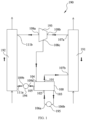
- FIG. 1 is a structural block diagram of an embodiment of a refrigeration system 190 of the present application that is used to show a connection relationship of various components in a two-stage compression refrigeration system.
- the refrigeration system 190 comprises a compressor 193, a condenser 191, an economizer 100, a second-stage throttling device 194, and an evaporator 192, which are connected in turn through a pipe to form a refrigerant circulation loop.
- the economizer 100 internally comprises a heat exchange cavity 218 and a gas-liquid separation cavity 217 (see FIG. 2A ).
- the compressor 193 has an air suction port 108a, an exhaust port 108b, and an air supplementing port 108c.
- the condenser 191 has an inlet 107a and an outlet 107b.
- the second-stage throttling device 194 has an inlet 109a and an outlet 109b.
- the evaporator 192 has an inlet 111a and an outlet 111b.
- the economizer 100 has an inlet 101 of the heat exchange cavity, a gas outlet 104 of the gas-liquid separation cavity, and a liquid outlet 105 of the gas-liquid separation cavity.
- the refrigeration system 190 further comprises a first-stage throttling device 195.
- the first-stage throttling device 195 has an inlet 106a and an outlet 106b.
- the economizer 100 also has an outlet 102 of the heat exchange cavity and an inlet 103 of the gas-liquid separation cavity.
- the exhaust port 108b of the compressor 193 is in fluid communication with the inlet 107a of the condenser 191, the outlet 107b of the condenser 191 is in fluid communication with the inlet 101 of the heat exchange cavity of the economizer 100, and the inlet 101 of the heat exchange cavity is provided below the outlet 107b of the condenser 191, the outlet 102 of the heat exchange cavity of the economizer 100 is in fluid communication with the inlet 106a of the first-stage throttling device 195, the outlet 106b of the first-stage throttling device 195 is in fluid communication with the inlet 103 of the gas-liquid separation cavity of the economizer 100, the gas outlet 104 of the gas-liquid separation cavity of the economizer 100 is in fluid communication with the air supplementing port 108c of the compressor 193, the liquid outlet 105 of the gas-liquid separation cavity of the economizer 100 is in fluid communication with the inlet 109a of the second-stage throttling device 194, the outlet
- the refrigeration system 190 is filled with refrigerants.
- the operation process of the refrigeration system 190 is briefly described below:
- a low-temperature and low-pressure gas refrigerant is compressed into a high-temperature and high-pressure gas refrigerant. Then, the high-temperature and high-pressure gas refrigerant flows into the condenser 191, and releases heat and is condensed into a high-pressure liquid refrigerant in the condenser 191.
- the high-pressure liquid refrigerant enters the economizer 100 through the inlet 101 of the heat exchange cavity. In the economizer 100, the high-pressure liquid refrigerant first passes through the heat exchange cavity 218 (see FIGs.
- a medium-pressure liquid refrigerant and gas refrigerant mixture (hereinafter referred to as a gas-liquid mixture) is obtained, and then enters the gas-liquid separation cavity 217 (see FIGs.
- the throttled low-pressure refrigerant enters the evaporator 192 to absorb heat and evaporate into a gas refrigerant, and finally returns to the compressor 193 from the air suction port 108a to be recompressed into a high-temperature and high-pressure gas refrigerant. In this way, a continuous refrigeration cycle is completed.
- FIGs. 2A and 2B show a specific structure of a first embodiment of the economizer 100 in FIG. 1 ; wherein FIG. 2A is a schematic radial cross-sectional view of the economizer 100 that is used to show the general structure of the economizer 100 in the width direction and the height direction, and FIG. 2B is a schematic axial cross-sectional view of the economizer 100 that is used to show the general structure of the economizer 100 in the length direction and the height direction.
- the economizer 100 comprises an outer shell 210, and an inside of the outer shell 210 forms a heat exchange cavity 218 and a gas-liquid separation cavity 217.
- the outer shell 210 has a length direction L, a width direction W, and a height direction H, and the heat exchange cavity 218 and the gas-liquid separation cavity 217 extend along the common length direction L.
- the economizer 100 further comprises an inner shell 212, wherein the outer shell 210 and the inner shell 212 are generally cylindrical, and their axial direction is the length direction L.
- the outer shell 210 and the inner shell 212 are coaxially provided.
- the outer shell 210 is provided surrounding the inner shell 212, an inside of the inner shell 212 forms a generally cylindrical heat exchange cavity 218, and a generally annular cylindrical gas-liquid separation cavity 217 is formed between the inner shell 212 and the outer shell 210.
- the economizer 100 further comprises a heat exchange tube bundle 220.
- the heat exchange tube bundle 220 is provided in the heat exchange cavity 218, and each heat exchange tube in the heat exchange tube bundle 220 extends along the length direction L.
- the outer shell 210 further comprises a front tube plate 228 and a rear tube plate 229, which are provided at two ends of the outer shell 210 in the length direction L, and are used to close the heat exchange cavity 218 and the gas-liquid separation cavity 217.
- each heat exchange tube in the heat exchange tube bundle 220 is respectively supported on the front tube plate 228 and the rear tube plate 229, and the inside of the heat exchange tube is in fluid communication with a front water tank 226 and a rear water tank 227 through the front tube plate 228 and the rear tube plate 229, respectively.
- the front end of the heat exchange tube is in fluid communication with a water inlet 224 through the front tube plate 228 and the front water tank 226, and the rear end of the heat exchange tube is in fluid communication with a water outlet 225 through the rear tube plate 229 and the rear water tank 227.
- the water inlet 224 and the water outlet 225 can be in fluid communication with a cooling medium, and in fluid communication with the inside of each heat exchange tube in the heat exchange tube bundle 220, for providing the cooling medium for heat exchange, such as cold water, to the inside of the heat exchange tube.
- the cooling medium flows from left to right along the length direction L inside each heat exchange tube of the heat exchange tube bundle.
- the inlet 101 of the heat exchange cavity and the outlet 102 of the heat exchange cavity are provided on the inner shell 212 and are in fluid communication with the heat exchange cavity 218.
- the inlet 101 of the heat exchange cavity and the outlet 102 of the heat exchange cavity are provided at the top and bottom in the height direction H of the inner shell 212, respectively, such that a refrigerant flowing into the heat exchange cavity 218 from the inlet 101 of the heat exchange cavity flows generally from top to bottom.
- the inlet 101 of the heat exchange cavity and the outlet 102 of the heat exchange cavity are provided generally in the middle in the length direction L of the inner shell 212.
- a pass partition plate 221 is also provided in the heat exchange cavity 218.
- the pass partition plate 221 is provided laterally on a refrigerant flow path between the inlet 101 of the heat exchange cavity and the outlet 102 of the heat exchange cavity, such that after entering the heat exchange cavity 218 from the inlet 101 of the heat exchange cavity, the refrigerant flows to the left and right sides in the length direction L because of being blocked by the pass partition plate 221 to be subjected to full heat exchange with the cooling medium through an outer wall of the heat exchange tube, and meanwhile flows downward to be discharged from the outlet 102 of the heat exchange cavity under the action of gravity.
- the cooling medium flowing in the heat exchange tubes of the heat exchange tube bundle 220 is cold water to further cool the refrigerant flowing in from the inlet 101 of the heat exchange cavity, such that the refrigerant reaches a subcooled liquid state.
- the first-stage throttling device 195 is connected between the outlet 102 of the heat exchange cavity and the inlet 103 of the gas-liquid separation cavity, such that the subcooled liquid refrigerant flowing out from the outlet 102 of the heat exchange cavity can be throttled by the first-stage throttling device 195, and then the gas-liquid mixture obtained by throttling is transported from the inlet 103 of the gas-liquid separation cavity to the gas-liquid separation cavity 217 for gas-liquid separation.
- the inlet 103 of the gas-liquid separation cavity, the gas outlet 104 of the gas-liquid separation cavity, and the liquid outlet 105 of the gas-liquid separation cavity are provided on the outer shell 210 and are in fluid communication with the gas-liquid separation cavity 217.
- the inlet 103 of the gas-liquid separation cavity and the gas outlet 104 of the gas-liquid separation cavity are provided to be spaced by a certain distance in the length direction L of the outer shell 210, such that a gas flow formed by the refrigerant can have a certain flow stoke.
- a gas-liquid separation cavity inlet tube 219 is connected to the inlet 103 of the gas-liquid separation cavity.
- the gas-liquid separation cavity inlet tube 219 communicates with an outlet of the first-stage throttling device 195, and the gas-liquid separation cavity inlet tube 219 extends along a tangential direction of the outer shell 210 to guide the gas-liquid mixture discharged from the first-stage throttling device 195 into the gas-liquid separation cavity 217 along a tangential direction of the gas-liquid separation cavity 217.
- a gas flow shown by the arrow and flowing rotationally in a spiral shape along the length direction L is formed in the gas-liquid separation cavity 217.
- the gas refrigerants and the liquid refrigerants have different densities, when they flow rotationally in a spiral shape together, a centrifugal force experienced by the liquid refrigerants is greater than that experienced by the gas refrigerants, so that the gas-liquid mixture can realize gas-liquid separation under the action of the centrifugal force; wherein the gas refrigerants with lower density continue to flow forward in a spiral shape until they are discharged from the gas outlet 104 of the gas-liquid separation cavity, and wherein the liquid refrigerants with higher density adhere to the outer surface of the inner shell 212 and are collected to the bottom of the gas-liquid separation cavity 217 to form a liquid level of a certain height until they flow out from the liquid outlet 105 of the gas-liquid separation cavity.
- the gas-liquid separation cavity inlet tube 219 extends upward generally along the tangential direction of the outer shell 210, such that the inlet 103 of the gas-liquid separation cavity is generally close to the right side of the bottom of the outer shell 210.
- the economizer 100 further comprises a filter screen 222 and a liquid baffle 223.
- the filter screen 222 is longitudinally provided in the gas-liquid separation cavity 217 and is provided on a flow path of the gas flow formed by the gas-liquid mixture to absorb the liquid refrigerants in the gas flow.
- multiple filter screens 222 may also be provided at intervals in the length direction L.
- the liquid baffle 223 is provided at the gas outlet 104 of the gas-liquid separation cavity to further prevent liquid droplets from being entrained in the gas flow discharged from the gas outlet 104 of the gas-liquid separation cavity.
- the heat exchange cavity 218 and the gas-liquid separation cavity 217 are provided in the outer shell 210 of the economizer 100.
- the refrigerant is first subjected to heat exchange in the heat exchange cavity 218 to be subcooled, and is then throttled by the first-stage throttling device 195 into a gas-liquid mixture, and then the gas-liquid mixture is subjected to gas-liquid separation in the gas-liquid separation cavity 217 through the principle of centrifugal separation. Therefore, the economizer 100 can realize both the heat exchange function and the gas-liquid separation function.
- the inner shell 212 is provided inside the outer shell 210, which not only has a compact structure and saves space, but also has a good gas-liquid separation effect by using a centrifugal force.
- a shell of the condenser can be smaller in size.
- the size of the shell of the condenser is the same, the number of the heat exchange tubes in the condenser is increased.
- the outer shell 210 and the inner shell 212 are coaxially cylindrical. In some other embodiments, the outer shell 210 and the inner shell 212 may also be provided non-axially.
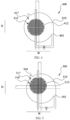
- FIG. 3 is a schematic radial cross-sectional view of a second embodiment of the economizer in FIG. 1 , showing another embodiment of the economizer.
- the economizer 300 similar to the economizer 100, the economizer 300 further comprises a cylindrical outer shell 310 and a cylindrical inner shell 312.
- the inner shell 312 is provided inside the outer shell 310, such that an inside of the inner shell 312 forms a heat exchange cavity 318, and a gas-liquid separation cavity 317 is formed between the inner shell 312 and the outer shell 310.
- the axial directions of the outer shell 310 and the inner shell 312 form a length direction L.
- the outer shell 310 and the inner shell 312 are no longer coaxially provided.
- the axes of the outer shell 310 and the inner shell 312 are at the same position in the width direction W, but are staggered in the height direction H.
- the axis of the inner shell 312 is offset from the axis of the outer shell 310 along the height direction H in a direction away from an inlet 303 of the gas-liquid separation cavity.
- FIG. 4 is a schematic radial cross-sectional view of a third embodiment of the economizer in FIG. 1 , showing yet another embodiment of the economizer.
- the economizer 400 similar to the economizer 100, the economizer 400 further comprises a cylindrical outer shell 410 and a cylindrical inner shell 412.
- the inner shell 412 is provided inside the outer shell 410, such that an inside of the inner shell 412 forms a heat exchange cavity 418, and a gas-liquid separation cavity 417 is formed between the inner shell 412 and the outer shell 410.
- the axial directions of the outer shell 410 and the inner shell 412 form a length direction L.
- the outer shell 410 and the inner shell 412 are not coaxially provided either.
- the axes of the outer shell 410 and the inner shell 412 are at the same position in the height direction H, but are staggered in the width direction W.
- the axis of the inner shell 412 is offset from the axis of the outer shell 410 along the width direction W in a direction away from an inlet 403 of the gas-liquid separation cavity.
- FIG. 5 is a schematic radial cross-sectional view of a fourth embodiment of the economizer in FIG. 1 , showing yet another embodiment of the economizer.
- the economizer 500 further comprises a cylindrical outer shell 510 and a cylindrical inner shell 512.
- the inner shell 512 is provided inside the outer shell 510, such that an inside of the inner shell 512 forms a heat exchange cavity 518, and a gas-liquid separation cavity 517 is formed between the inner shell 512 and the outer shell 510.
- the axial directions of the outer shell 510 and the inner shell 512 form a length direction L.
- the outer shell 510 and the inner shell 512 are not coaxially provided. However, what is different from the economizer 300 is that the axes of the outer shell 510 and the inner shell 512 are staggered in both the height direction H and the width direction W. For example, the axis of the inner shell 512 is offset from the axis of the outer shell 510 along both the width direction W and the height direction H in a direction away from an inlet 503 of the gas-liquid separation cavity.
- each outer shell and the corresponding inner shell are not coaxially provided, but the inner shell is provided offset from the axis of the outer shell in a direction away from the inlet of the gas-liquid separation cavity.
- Such an arrangement can increase the space at the inlet of the gas-liquid separation cavity, which is beneficial to reducing the pressure drop of the gas-liquid mixture in the gas-liquid separation cavity.
- the pressure drop between the inlet 103 of the gas-liquid separation cavity and the gas outlet 104 of the gas-liquid separation cavity is generally 5.44 kPa, but in the economizer 500 as shown in FIG. 5 , the pressure drop between the inlet 503 of the gas-liquid separation cavity and the gas outlet 504 of the gas-liquid separation cavity is only 3.89 kPa.
- inlet of the gas-liquid separation cavity is provided close to the side of the bottom of the outer shell, providing the inner shell away from the inlet of the gas-liquid separation cavity can be also beneficial to reducing the disturbance of the gas flow to the liquid level at the bottom of the outer shell, thereby improving the stability of the liquid level formed by the liquid refrigerants.
- FIG. 6 is a schematic axial cross-sectional view of a fifth embodiment of the economizer in FIG. 1 , showing yet another embodiment of the economizer.
- the structure of the economizer 600 is generally the same as that of the economizer 100. The only difference is that multiple liquid outlets 605 of the gas-liquid separation cavity are provided along the length direction L, and the economizer 600 further comprises a plurality of outlet branch tubes 631 and liquid collection tubes 632, which are connected to the liquid outlet 605 of the gas-liquid separation cavity.
- each outlet branch tube 631 is connected to the corresponding liquid outlet 605 of the gas-liquid separation cavity, and the other end of each outlet branch tube 631 is connected to the liquid collection tube 632 along a length direction of the liquid collection tube 632.
- the length direction of the liquid collection tube 632 is generally the same as the length direction L, and each outlet branch tube 631 is arranged along the length direction of the liquid collection tube 632 and is respectively in fluid communication with the liquid collection tube 632. Therefore, the liquid refrigerants separated in the economizer 600 can be discharged through the liquid outlets 605 of the gas-liquid separation cavity and the corresponding outlet branch tubes 631, and then collected through the liquid collection tubes 632 and transported to the second-stage throttling device 194.
- the liquid refrigerants after gas-liquid separation can be discharged in a timelier manner, so as to reduce or prevent the liquid refrigerants from forming a liquid level at the bottom of the gas-liquid separation cavity 217.
- FIG. 7 is a schematic axial cross-sectional view of a sixth embodiment of the economizer in FIG. 1 , showing yet another embodiment of the economizer.
- the structure of the economizer 700 is generally the same as that of the economizer 100. The only difference is that the economizer further comprises a liquid storage tank 735 and a liquid level sensor 736, wherein the liquid storage tank 735 is provided outside an outer shell 710 of the economizer 700, and is in fluid communication with a liquid outlet 705 of the gas-liquid separation cavity to receive the liquid refrigerants discharged from the liquid outlet 705 of the gas-liquid separation cavity and store these liquid refrigerants in the liquid storage tank 735.
- the liquid level sensor 736 is communicatively connected to the liquid storage tank 735 and to the second-stage throttling device 194.
- the liquid level sensor 736 is used to detect a liquid level height of the liquid refrigerants stored in the liquid storage tank 735, and control an opening degree of the second-stage throttling device 194 based on the detection result.
- the number of the liquid outlets 705 of the gas-liquid separation cavity is two, and the two liquid outlets of the gas-liquid separation cavity are provided on two sides of a filter screen 722 in a length direction L, respectively.
- the economizer 700 can provide the liquid refrigerants to the second-stage throttling device 194 more stably, and adjust the opening degree of the second-stage throttling device 194 according to the amount of the liquid refrigerants, so that the operation of the refrigeration system 190 is more stable and reliable.
- FIGs. 6 and 7 the structure of a gas-liquid separation cavity liquid outlet portion of the economizer is improved, so that the liquid level in the gas-liquid separation cavity can be less disturbed by the gas flow, thereby providing the liquid refrigerants to the second-stage throttling device more stably and reliably.
- These structures can be used in combination with any of the embodiments in FIGs. 2A and 2B and FIGs. 3 to 5 to achieve better results.
- FIGs. 8A and 8B are schematic structural diagrams of a seventh embodiment of the economizer in FIG. 1 , wherein FIG. 8A is a schematic radial cross-sectional view of the seventh embodiment of the economizer, and FIG. 8B is a schematic axial cross-sectional view of the seventh embodiment of the economizer.
- the economizer 800 comprises an outer shell 810 and a partition plate 841.
- the outer shell 810 is cylindrical.
- the outer shell 810 also has a length direction L, a width direction W, and a height direction H.
- the partition plate 841 is provided laterally in the outer shell 810 along the width direction W and extends along the length direction L to divide the cylindrical space inside the outer shell 810 into a heat exchange cavity 818 and a gas-liquid separation cavity 817.
- the gas-liquid separation cavity 817 is located above the heat exchange cavity 818.
- the heat exchange cavity 818 and the gas-liquid separation cavity 817 have a common length direction L, but in this embodiment, they are separated by the partition plate 841 and therefore no longer have an axial direction.
- the outer shell 810 comprises a front tube plate 828 and a rear tube plate 829 for closing the heat exchange cavity 818 and the gas-liquid separation cavity 817.
- the heat exchange tube bundle 820 extends along the length direction L to be supported on the front tube plate 828 and the rear tube plate 829, and is in fluid communication with a cooling medium through the front tube plate 828 and the rear tube plate 829.
- the economizer 800 also has an inlet 801 of the heat exchange cavity, an outlet 802 of the heat exchange cavity, an inlet 803 of the gas-liquid separation cavity, a gas outlet 804 of the gas-liquid separation cavity, and a liquid outlet 805 of the gas-liquid separation cavity.
- the inlet 801 of the heat exchange cavity and the outlet 802 of the heat exchange cavity are provided at the bottom of the outer shell 810, and are provided close to two ends in the length direction L.
- the inlet 801 of the heat exchange cavity is provided at the bottom of the outer shell 810 close to the front tube plate 828
- the outlet 802 of the heat exchange cavity is provided at the bottom of the outer shell 810 close to the rear tube plate 829.
- a flow direction of the cooling medium in order to improve the heat exchange effect, can be set to be opposite to a flow direction of the refrigerant.
- a water inlet 824 is provided on the outer side of the rear tube plate 829, and a water outlet 825 is provided on the outer side of the front tube plate 828.
- the heat exchange cavity 818 is also internally provided with a plurality of baffle plates 843, and the plurality of baffle plates 843 are provided along the length direction L on a flow path of the liquid refrigerants in the heat exchange cavity 818.
- the baffle plates 843 are used to change the flow direction of the liquid refrigerants, so that the liquid refrigerants discharged from the condenser 191 can flow along the direction shown by arrow B, thereby extending a flow distance of the liquid refrigerants, so that the liquid refrigerants can be subjected to heat exchange fully with the cooling medium through the heat exchange tube bundle 820.
- these baffle plates 843 are connected to the outer shell 810 and the partition plate 841 in sequence, and are correspondingly spaced by a certain distance from the partition plate 841 and the outer shell 810 for the liquid refrigerants to flow through.
- the first-stage throttling device 195 is also provided between the outlet 802 of the heat exchange cavity and the inlet 803 of the gas-liquid separation cavity for throttling the subcooled liquid refrigerants into two-phase refrigerants, that is, a gas-liquid mixture.
- the inlet 803 of the gas-liquid separation cavity and the gas outlet 804 of the gas-liquid separation cavity are provided at the top of the outer shell 810, and are provided close to two ends in the length direction L.
- the inlet 803 of the gas-liquid separation cavity is provided at the top of the outer shell 810 close to the rear tube plate 829
- the gas outlet 804 of the gas-liquid separation cavity is provided at the top of the outer shell 810 closet to the front tube plate 828, such that the gas-liquid mixture entering the gas-liquid separation cavity 817 from the inlet 803 of the gas-liquid separation cavity can generally form a gas flow flowing along the direction shown by arrow C.
- the gas-liquid mixture can complete gas-liquid separation under the action of gravity, wherein the gas refrigerants flow along the direction shown by arrow C and are then discharged from the gas outlet 804 of the gas-liquid separation cavity, and the liquid refrigerants are collected above the partition plate 841 at the bottom of the gas-liquid separation cavity 817 to form a liquid level of a certain height.
- the gas-liquid separation cavity 817 is also provided with a plurality of filter screens 822 therein. These filter screens 822 are provided along the length direction L on a flow path of the gas flow in the gas-liquid separation cavity 817 to further improve the effect of gas-liquid separation, so that the liquid refrigerants can be more fully separated from the gas flow.
- the liquid outlet 805 of the gas-liquid separation cavity is provided on the outer shell 810 on one side close to the gas outlet 804 of the gas-liquid separation cavity.
- the liquid outlet 805 of the gas-liquid separation cavity is provided at a position, close to the partition plate 841, of the front tube plate 828, so as to discharge the liquid refrigerants collected on the partition plate 841 in a timely manner.
- the economizer of the present embodiment only needs an outer shell and a partition plate, and does not need an inner shell, to form a heat exchange cavity and a gas-liquid separation cavity.
- the structure is simpler, further saving manufacturing costs.
- the heat exchange cavity and the gas-liquid separation cavity are provided in the shell, the gas-liquid separation function of the economizer can be achieved, the heat exchange function of a subcooler can also be achieved, such that the structure of the two-stage compression refrigeration system with the function requirements of the subcooler can be more compact.
- the heat exchange tube bundle used to achieve the subcooling effect in the present application is provided outside the condenser, the refrigerant charge quantity in the refrigeration system can also be reduced, and the size requirements of the condenser can be reduced.
- annular columnar gas-liquid separation cavity can be formed by providing an outer shell and an inner shell with appropriate shapes, so that the centrifugal force of the gas flow when rotating in the gas-liquid separation cavity can be used to achieve the gas-liquid separation function, and thus the gas-liquid separation effect achieved by the economizer can also be improved.
Landscapes
- Engineering & Computer Science (AREA)
- Physics & Mathematics (AREA)
- Mechanical Engineering (AREA)
- Thermal Sciences (AREA)
- General Engineering & Computer Science (AREA)
- Chemical & Material Sciences (AREA)
- Analytical Chemistry (AREA)
- Power Engineering (AREA)
- Heat-Exchange Devices With Radiators And Conduit Assemblies (AREA)
Abstract
Description
- The present application relates to an economizer and a refrigeration system including same, and is particularly suitable for two-stage compression refrigeration systems.
- A refrigeration system generally comprises a compressor, a condenser, a throttling device, and an evaporator, which are connected in turn to form a refrigerant circulation system to heat or cool the outside. Some refrigeration systems further comprise a subcooler and an economizer. The subcooler is provided inside the condenser to further cool condensed refrigerants to increase the refrigeration efficiency and the cooling capacity of the refrigeration systems. The economizer is used to carry out gas-liquid separation on the gas-liquid two-phase refrigerants after passing through a first-stage throttling device, wherein gas refrigerants return to an air supplementing port of the compressor, and liquid refrigerants enter the evaporator for evaporation after passing through a second-stage throttling device.
- At least one object of the first aspect of the present application is to provide an economizer that can perform not only a function of gas-liquid separation but also a function of heat exchange. The economizer comprises: an outer shell that internally comprises a heat exchange cavity and a gas-liquid separation cavity and has a length direction; a heat exchange tube bundle provided in the heat exchange cavity and extending along the length direction; an inlet of the heat exchange cavity and an outlet of the heat exchange cavity, which are in fluid communication with the heat exchange cavity; and an inlet of the gas-liquid separation cavity, a gas outlet of the gas-liquid separation cavity, and a liquid outlet of the gas-liquid separation cavity, which are provided on the outer shell and are in fluid communication with the gas-liquid separation cavity, wherein the inlet of the gas-liquid separation cavity is in fluid communication with the outlet of the heat exchange cavity through a first-stage throttling device, and the inlet of the gas-liquid separation cavity and the gas outlet of the gas-liquid separation cavity are provided to be spaced by a certain distance in the length direction; and wherein the economizer is configured to enable refrigerants from a condenser to be subjected to heat exchange in the heat exchange cavity first, and then to be subjected to gas-liquid separation in the gas-liquid separation cavity after passing through the first-stage throttling device, such that gas refrigerants flow out of the gas outlet of the gas-liquid separation cavity, and liquid refrigerants flow out of the liquid outlet of the gas-liquid separation cavity.
- According to the above first aspect, the economizer further comprises an inner shell, wherein the inner shell and the outer shell are cylindrical, the outer shell is provided surrounding the inner shell, an axial direction of the inner shell and the outer shell is the length direction, an inside of the inner shell forms the heat exchange cavity, and the gas-liquid separation cavity is formed between the inner shell and the outer shell; and wherein the inlet of the heat exchange cavity and the outlet of the heat exchange cavity are provided on the inner shell.
- According to the above first aspect, the economizer further comprises a gas-liquid separation cavity inlet tube, wherein the gas-liquid separation cavity inlet tube is connected to the inlet of the gas-liquid separation cavity, and the gas-liquid separation cavity inlet tube extends along a tangential direction of the outer shell, so that the refrigerants flow spirally along the length direction around the inner shell in the gas-liquid separation cavity, thereby achieving gas-liquid separation under the action of centrifugal force.
- According to the above first aspect, the inner shell and the outer shell are coaxially provided.
- According to the above first aspect, the inlet of the gas-liquid separation cavity is provided on one side of the outer shell close to a bottom; and in a width direction and/or a height direction of the inner shell and the outer shell, an axis of the inner shell is arranged offset from an axis of the outer shell, and the inner shell is arranged away from the inlet of the gas-liquid separation cavity.
- According to the above first aspect, the economizer comprises a partition plate, wherein the partition plate divides an inside of the outer shell into the heat exchange cavity and the gas-liquid separation cavity, and the inlet of the heat exchange cavity and the outlet of the heat exchange cavity are provided on the outer shell; and the inlet of the gas-liquid separation cavity is configured to guide the refrigerants into the gas-liquid separation cavity along one end of the gas-liquid separation cavity in a length direction, such that the refrigerants flow along the length direction in the gas-liquid separation cavity, thereby achieving gas-liquid separation under the action of gravity.
- According to the above first aspect, the economizer further comprises at least one filter screen, and the at least one filter screen is provided on a flow path of the refrigerants in the gas-liquid separation cavity.
- According to the above first aspect, the liquid outlet of the gas-liquid separation cavity is connected to a liquid collection tube and a plurality of outlet branch tubes, and the plurality of outlet branch tubes are each in fluid communication with the liquid collection tube along a length direction of the liquid collection tube.
- According to the above first aspect, the refrigerants from the condenser are subjected to heat exchange in the heat exchange cavity through outer walls of heat exchange tubes in the heat exchange tube bundle.
- According to the above first aspect, the gas refrigerants flow out of the gas outlet of the gas-liquid separation cavity and are provided to an air supplementing port of a compressor, and the liquid refrigerants flow out of the liquid outlet of the gas-liquid separation cavity and are provided to a second-stage throttling device.
- According to the above first aspect, the economizer further comprises a liquid storage tank and a liquid level sensor, wherein the liquid storage tank is in fluid communication with the liquid outlet of the gas-liquid separation cavity to receive the liquid refrigerants, and the liquid level sensor is in communication connection with the second-stage throttling device; and wherein the liquid level sensor is configured to detect a liquid level height in the liquid storage tank, and to control an opening degree of the second-stage throttling device based on a detection result.
- According to the above first aspect, the inlet of the gas-liquid separation cavity and the gas outlet of the gas-liquid separation cavity are provided close to two ends of the outer shell in the length direction.
- At least one object of the second aspect of the present application is to provide a refrigeration system, comprising: a compressor, a condenser, an economizer, a second-stage throttling device, and an evaporator, which are provided in a refrigerant circuit; wherein the economizer comprises: an outer shell that internally comprises a heat exchange cavity and a gas-liquid separation cavity and has a length direction; a heat exchange tube bundle provided in the heat exchange cavity and extending along the length direction; an inlet of the heat exchange cavity and an outlet of the heat exchange cavity, which are in fluid communication with the heat exchange cavity, the inlet of the heat exchange cavity being in fluid communication with an outlet of the condenser; and an inlet of the gas-liquid separation cavity, a gas outlet of the gas-liquid separation cavity, and a liquid outlet of the gas-liquid separation cavity, which are provided on the outer shell and are in fluid communication with the gas-liquid separation cavity, wherein the inlet of the gas-liquid separation cavity is in fluid communication with the outlet of the heat exchange cavity through a first-stage throttling device, the gas outlet of the gas-liquid separation cavity is in fluid communication with an air supplementing port of the compressor, the liquid outlet of the gas-liquid separation cavity is in fluid communication with an inlet of the second-stage throttling device, and the inlet of the gas-liquid separation cavity and the gas outlet of the gas-liquid separation cavity are provided to be spaced by a certain distance in the length direction; and wherein the economizer is configured to enable refrigerants from the condenser to be subjected to heat exchange in the heat exchange cavity first, and then to be subjected to gas-liquid separation in the gas-liquid separation cavity after passing through the first-stage throttling device, such that gas refrigerants flow out of the gas outlet of the gas-liquid separation cavity and are provided to the air supplementing port of the compressor, and liquid refrigerants flow out of the liquid outlet of the gas-liquid separation cavity and are provided to the second-stage throttling device.
-
-
FIG. 1 is a structural block diagram of an embodiment of a refrigeration system of the present application; -
FIG. 2A is a schematic radial cross-sectional view of a first embodiment of the economizer inFIG. 1 ; -
FIG. 2B is a schematic axial cross-sectional view of the economizer inFIG. 2A ; -
FIG. 3 is a schematic radial cross-sectional view of a second embodiment of the economizer inFIG. 1 ; -
FIG. 4 is a schematic radial cross-sectional view of a third embodiment of the economizer inFIG. 1 ; -
FIG. 5 is a schematic radial cross-sectional view of a fourth embodiment of the economizer inFIG. 1 ; -
FIG. 6 is a schematic axial cross-sectional view of a fifth embodiment of the economizer inFIG. 1 ; -
FIG. 7 is a schematic axial cross-sectional view of a sixth embodiment of the economizer inFIG. 1 ; -
FIG. 8A is a schematic radial cross-sectional view of a seventh embodiment of the economizer inFIG. 1 ; and -
FIG. 8B is a schematic axial cross-sectional view of the economizer inFIG. 8A . - Various specific embodiments of the present application will be described below with reference to the accompanying drawings, which constitute a part of the specification. It should be understood that although terms, such as "front," "rear," "upper," "lower," "left," "right," "top," "bottom," etc., that represent directions are used in the present application to describe various example structural parts and elements of the present application, these terms used herein are determined based on example orientations shown in the accompanying drawings for ease of illustration only. Since the embodiments disclosed in the present application may be disposed in different directions, these terms that represent directions are for illustration only and should not be regarded as limiting.
-
FIG. 1 is a structural block diagram of an embodiment of arefrigeration system 190 of the present application that is used to show a connection relationship of various components in a two-stage compression refrigeration system. As shown inFIG. 1 , therefrigeration system 190 comprises acompressor 193, acondenser 191, aneconomizer 100, a second-stage throttling device 194, and anevaporator 192, which are connected in turn through a pipe to form a refrigerant circulation loop. Theeconomizer 100 internally comprises aheat exchange cavity 218 and a gas-liquid separation cavity 217 (seeFIG. 2A ). - Specifically, the
compressor 193 has anair suction port 108a, anexhaust port 108b, and anair supplementing port 108c. Thecondenser 191 has aninlet 107a and anoutlet 107b. The second-stage throttling device 194 has aninlet 109a and anoutlet 109b. Theevaporator 192 has an inlet 111a and an outlet 111b. Theeconomizer 100 has aninlet 101 of the heat exchange cavity, agas outlet 104 of the gas-liquid separation cavity, and aliquid outlet 105 of the gas-liquid separation cavity. Therefrigeration system 190 further comprises a first-stage throttling device 195. The first-stage throttling device 195 has aninlet 106a and anoutlet 106b. Theeconomizer 100 also has anoutlet 102 of the heat exchange cavity and aninlet 103 of the gas-liquid separation cavity. - The
exhaust port 108b of thecompressor 193 is in fluid communication with theinlet 107a of thecondenser 191, theoutlet 107b of thecondenser 191 is in fluid communication with theinlet 101 of the heat exchange cavity of theeconomizer 100, and theinlet 101 of the heat exchange cavity is provided below theoutlet 107b of thecondenser 191, theoutlet 102 of the heat exchange cavity of theeconomizer 100 is in fluid communication with theinlet 106a of the first-stage throttling device 195, theoutlet 106b of the first-stage throttling device 195 is in fluid communication with theinlet 103 of the gas-liquid separation cavity of theeconomizer 100, thegas outlet 104 of the gas-liquid separation cavity of theeconomizer 100 is in fluid communication with theair supplementing port 108c of thecompressor 193, theliquid outlet 105 of the gas-liquid separation cavity of theeconomizer 100 is in fluid communication with theinlet 109a of the second-stage throttling device 194, theoutlet 109b of the second-stage throttling device 194 is in fluid communication with the inlet 111a of theevaporator 192, and the outlet 111b of theevaporator 192 is in fluid communication with theair suction port 108a of thecompressor 193. - The
refrigeration system 190 is filled with refrigerants. The operation process of therefrigeration system 190 is briefly described below: - In the
compressor 193, a low-temperature and low-pressure gas refrigerant is compressed into a high-temperature and high-pressure gas refrigerant. Then, the high-temperature and high-pressure gas refrigerant flows into thecondenser 191, and releases heat and is condensed into a high-pressure liquid refrigerant in thecondenser 191. The high-pressure liquid refrigerant enters theeconomizer 100 through theinlet 101 of the heat exchange cavity. In theeconomizer 100, the high-pressure liquid refrigerant first passes through the heat exchange cavity 218 (seeFIGs. 2A and2B ), and is subjected to heat exchange in theheat exchange cavity 218 to be further cooled into a subcooled liquid refrigerant, and then the subcooled liquid refrigerant flows out from theoutlet 102 of the heat exchange cavity to the first-stage throttling device 195. After the first throttling, a medium-pressure liquid refrigerant and gas refrigerant mixture (hereinafter referred to as a gas-liquid mixture) is obtained, and then enters the gas-liquid separation cavity 217 (seeFIGs. 2A and2B ) through theinlet 103 of the gas-liquid separation cavity for gas-liquid separation, wherein the gas refrigerant flows out from thegas outlet 104 of the gas-liquid separation cavity and returns to thecompressor 193 via theair supplementing port 108c to be recompressed into a high-temperature and high-pressure gas refrigerant; and wherein the liquid refrigerant flows out from theliquid outlet 105 of the gas-liquid separation cavity to the second-stage throttling device 194 for second throttling. The throttled low-pressure refrigerant enters theevaporator 192 to absorb heat and evaporate into a gas refrigerant, and finally returns to thecompressor 193 from theair suction port 108a to be recompressed into a high-temperature and high-pressure gas refrigerant. In this way, a continuous refrigeration cycle is completed. -
FIGs. 2A and2B show a specific structure of a first embodiment of theeconomizer 100 inFIG. 1 ; whereinFIG. 2A is a schematic radial cross-sectional view of theeconomizer 100 that is used to show the general structure of theeconomizer 100 in the width direction and the height direction, andFIG. 2B is a schematic axial cross-sectional view of theeconomizer 100 that is used to show the general structure of theeconomizer 100 in the length direction and the height direction. - As shown in
FIGs. 2A and2B , theeconomizer 100 comprises anouter shell 210, and an inside of theouter shell 210 forms aheat exchange cavity 218 and a gas-liquid separation cavity 217. Theouter shell 210 has a length direction L, a width direction W, and a height direction H, and theheat exchange cavity 218 and the gas-liquid separation cavity 217 extend along the common length direction L. Theeconomizer 100 further comprises aninner shell 212, wherein theouter shell 210 and theinner shell 212 are generally cylindrical, and their axial direction is the length direction L. In the present embodiment, theouter shell 210 and theinner shell 212 are coaxially provided. Theouter shell 210 is provided surrounding theinner shell 212, an inside of theinner shell 212 forms a generally cylindricalheat exchange cavity 218, and a generally annular cylindrical gas-liquid separation cavity 217 is formed between theinner shell 212 and theouter shell 210. - The
economizer 100 further comprises a heatexchange tube bundle 220. The heatexchange tube bundle 220 is provided in theheat exchange cavity 218, and each heat exchange tube in the heatexchange tube bundle 220 extends along the length direction L. Theouter shell 210 further comprises afront tube plate 228 and arear tube plate 229, which are provided at two ends of theouter shell 210 in the length direction L, and are used to close theheat exchange cavity 218 and the gas-liquid separation cavity 217. The two ends of each heat exchange tube in the heatexchange tube bundle 220 are respectively supported on thefront tube plate 228 and therear tube plate 229, and the inside of the heat exchange tube is in fluid communication with afront water tank 226 and arear water tank 227 through thefront tube plate 228 and therear tube plate 229, respectively. The front end of the heat exchange tube is in fluid communication with awater inlet 224 through thefront tube plate 228 and thefront water tank 226, and the rear end of the heat exchange tube is in fluid communication with awater outlet 225 through therear tube plate 229 and therear water tank 227. Thewater inlet 224 and thewater outlet 225 can be in fluid communication with a cooling medium, and in fluid communication with the inside of each heat exchange tube in the heatexchange tube bundle 220, for providing the cooling medium for heat exchange, such as cold water, to the inside of the heat exchange tube. The cooling medium flows from left to right along the length direction L inside each heat exchange tube of the heat exchange tube bundle. - The
inlet 101 of the heat exchange cavity and theoutlet 102 of the heat exchange cavity are provided on theinner shell 212 and are in fluid communication with theheat exchange cavity 218. In the present embodiment, theinlet 101 of the heat exchange cavity and theoutlet 102 of the heat exchange cavity are provided at the top and bottom in the height direction H of theinner shell 212, respectively, such that a refrigerant flowing into theheat exchange cavity 218 from theinlet 101 of the heat exchange cavity flows generally from top to bottom. Theinlet 101 of the heat exchange cavity and theoutlet 102 of the heat exchange cavity are provided generally in the middle in the length direction L of theinner shell 212. In order to allow the refrigerant flowing into theheat exchange cavity 218 from theinlet 101 of the heat exchange cavity to have a certain flow stroke, apass partition plate 221 is also provided in theheat exchange cavity 218. Thepass partition plate 221 is provided laterally on a refrigerant flow path between theinlet 101 of the heat exchange cavity and theoutlet 102 of the heat exchange cavity, such that after entering theheat exchange cavity 218 from theinlet 101 of the heat exchange cavity, the refrigerant flows to the left and right sides in the length direction L because of being blocked by thepass partition plate 221 to be subjected to full heat exchange with the cooling medium through an outer wall of the heat exchange tube, and meanwhile flows downward to be discharged from theoutlet 102 of the heat exchange cavity under the action of gravity. And in the present embodiment, the cooling medium flowing in the heat exchange tubes of the heatexchange tube bundle 220 is cold water to further cool the refrigerant flowing in from theinlet 101 of the heat exchange cavity, such that the refrigerant reaches a subcooled liquid state. - The first-
stage throttling device 195 is connected between theoutlet 102 of the heat exchange cavity and theinlet 103 of the gas-liquid separation cavity, such that the subcooled liquid refrigerant flowing out from theoutlet 102 of the heat exchange cavity can be throttled by the first-stage throttling device 195, and then the gas-liquid mixture obtained by throttling is transported from theinlet 103 of the gas-liquid separation cavity to the gas-liquid separation cavity 217 for gas-liquid separation. - The
inlet 103 of the gas-liquid separation cavity, thegas outlet 104 of the gas-liquid separation cavity, and theliquid outlet 105 of the gas-liquid separation cavity are provided on theouter shell 210 and are in fluid communication with the gas-liquid separation cavity 217. In the present embodiment, theinlet 103 of the gas-liquid separation cavity and thegas outlet 104 of the gas-liquid separation cavity are provided to be spaced by a certain distance in the length direction L of theouter shell 210, such that a gas flow formed by the refrigerant can have a certain flow stoke. In the present embodiment, a gas-liquid separationcavity inlet tube 219 is connected to theinlet 103 of the gas-liquid separation cavity. The gas-liquid separationcavity inlet tube 219 communicates with an outlet of the first-stage throttling device 195, and the gas-liquid separationcavity inlet tube 219 extends along a tangential direction of theouter shell 210 to guide the gas-liquid mixture discharged from the first-stage throttling device 195 into the gas-liquid separation cavity 217 along a tangential direction of the gas-liquid separation cavity 217. A gas flow shown by the arrow and flowing rotationally in a spiral shape along the length direction L is formed in the gas-liquid separation cavity 217. Since the gas refrigerants and the liquid refrigerants have different densities, when they flow rotationally in a spiral shape together, a centrifugal force experienced by the liquid refrigerants is greater than that experienced by the gas refrigerants, so that the gas-liquid mixture can realize gas-liquid separation under the action of the centrifugal force; wherein the gas refrigerants with lower density continue to flow forward in a spiral shape until they are discharged from thegas outlet 104 of the gas-liquid separation cavity, and wherein the liquid refrigerants with higher density adhere to the outer surface of theinner shell 212 and are collected to the bottom of the gas-liquid separation cavity 217 to form a liquid level of a certain height until they flow out from theliquid outlet 105 of the gas-liquid separation cavity. In the present embodiment, the gas-liquid separationcavity inlet tube 219 extends upward generally along the tangential direction of theouter shell 210, such that theinlet 103 of the gas-liquid separation cavity is generally close to the right side of the bottom of theouter shell 210. - The
economizer 100 further comprises afilter screen 222 and aliquid baffle 223. Thefilter screen 222 is longitudinally provided in the gas-liquid separation cavity 217 and is provided on a flow path of the gas flow formed by the gas-liquid mixture to absorb the liquid refrigerants in the gas flow. In order to further reduce the liquid refrigerants in the gas flow,multiple filter screens 222 may also be provided at intervals in the length direction L. Theliquid baffle 223 is provided at thegas outlet 104 of the gas-liquid separation cavity to further prevent liquid droplets from being entrained in the gas flow discharged from thegas outlet 104 of the gas-liquid separation cavity. - In the present embodiment, the
heat exchange cavity 218 and the gas-liquid separation cavity 217 are provided in theouter shell 210 of theeconomizer 100. The refrigerant is first subjected to heat exchange in theheat exchange cavity 218 to be subcooled, and is then throttled by the first-stage throttling device 195 into a gas-liquid mixture, and then the gas-liquid mixture is subjected to gas-liquid separation in the gas-liquid separation cavity 217 through the principle of centrifugal separation. Therefore, theeconomizer 100 can realize both the heat exchange function and the gas-liquid separation function. Theinner shell 212 is provided inside theouter shell 210, which not only has a compact structure and saves space, but also has a good gas-liquid separation effect by using a centrifugal force. - In addition, generally speaking, when a subcooler is provided in the condenser, a certain refrigerant charge quantity is required in the refrigeration system, so that the refrigerant that needs to be subcooled can immerse the heat exchange tube bundle. In the refrigeration system of the present embodiment, there is no need to provide the subcooler in the condenser. It is only necessary to provide the
inlet 101 of the heat exchange cavity below theoutlet 107b of thecondenser 191 to ensure that the heatexchange tube bundle 220 is immersed in the refrigerant. Therefore, a smaller refrigerant charge quantity is required in the condenser to achieve the same degree of subcooling. When the number of the heat exchange tubes in the condenser is the same, a shell of the condenser can be smaller in size. When the size of the shell of the condenser is the same, the number of the heat exchange tubes in the condenser is increased. - In the
economizer 100 of the present embodiment, theouter shell 210 and theinner shell 212 are coaxially cylindrical. In some other embodiments, theouter shell 210 and theinner shell 212 may also be provided non-axially. -
FIG. 3 is a schematic radial cross-sectional view of a second embodiment of the economizer inFIG. 1 , showing another embodiment of the economizer. As shown inFIG. 3 , similar to theeconomizer 100, theeconomizer 300 further comprises a cylindricalouter shell 310 and a cylindricalinner shell 312. Theinner shell 312 is provided inside theouter shell 310, such that an inside of theinner shell 312 forms aheat exchange cavity 318, and a gas-liquid separation cavity 317 is formed between theinner shell 312 and theouter shell 310. And the axial directions of theouter shell 310 and theinner shell 312 form a length direction L. - However, what is different from the
economizer 100 is that in theeconomizer 300, theouter shell 310 and theinner shell 312 are no longer coaxially provided. The axes of theouter shell 310 and theinner shell 312 are at the same position in the width direction W, but are staggered in the height direction H. For example, the axis of theinner shell 312 is offset from the axis of theouter shell 310 along the height direction H in a direction away from aninlet 303 of the gas-liquid separation cavity. -
FIG. 4 is a schematic radial cross-sectional view of a third embodiment of the economizer inFIG. 1 , showing yet another embodiment of the economizer. As shown inFIG. 4 , similar to theeconomizer 100, theeconomizer 400 further comprises a cylindricalouter shell 410 and a cylindricalinner shell 412. Theinner shell 412 is provided inside theouter shell 410, such that an inside of theinner shell 412 forms aheat exchange cavity 418, and a gas-liquid separation cavity 417 is formed between theinner shell 412 and theouter shell 410. And the axial directions of theouter shell 410 and theinner shell 412 form a length direction L. - In the
economizer 400, theouter shell 410 and theinner shell 412 are not coaxially provided either. However, what is different from theeconomizer 300 is that the axes of theouter shell 410 and theinner shell 412 are at the same position in the height direction H, but are staggered in the width direction W. For example, the axis of theinner shell 412 is offset from the axis of theouter shell 410 along the width direction W in a direction away from aninlet 403 of the gas-liquid separation cavity. -
FIG. 5 is a schematic radial cross-sectional view of a fourth embodiment of the economizer inFIG. 1 , showing yet another embodiment of the economizer. As shown inFIG. 5 , similar to theeconomizer 100, theeconomizer 500 further comprises a cylindricalouter shell 510 and a cylindricalinner shell 512. Theinner shell 512 is provided inside theouter shell 510, such that an inside of theinner shell 512 forms aheat exchange cavity 518, and a gas-liquid separation cavity 517 is formed between theinner shell 512 and theouter shell 510. And the axial directions of theouter shell 510 and theinner shell 512 form a length direction L. - In the
economizer 500, theouter shell 510 and theinner shell 512 are not coaxially provided. However, what is different from theeconomizer 300 is that the axes of theouter shell 510 and theinner shell 512 are staggered in both the height direction H and the width direction W. For example, the axis of theinner shell 512 is offset from the axis of theouter shell 510 along both the width direction W and the height direction H in a direction away from aninlet 503 of the gas-liquid separation cavity. - In the
economizer 300, theeconomizer 400, and theeconomizer 500 as shown inFIGs. 3 to 5 , each outer shell and the corresponding inner shell are not coaxially provided, but the inner shell is provided offset from the axis of the outer shell in a direction away from the inlet of the gas-liquid separation cavity. Such an arrangement can increase the space at the inlet of the gas-liquid separation cavity, which is beneficial to reducing the pressure drop of the gas-liquid mixture in the gas-liquid separation cavity. For example, under certain same operating conditions, in theeconomizer 100 as shown inFIGs. 2A and2B , the pressure drop between theinlet 103 of the gas-liquid separation cavity and thegas outlet 104 of the gas-liquid separation cavity is generally 5.44 kPa, but in theeconomizer 500 as shown inFIG. 5 , the pressure drop between theinlet 503 of the gas-liquid separation cavity and thegas outlet 504 of the gas-liquid separation cavity is only 3.89 kPa. - In addition, since the inlet of the gas-liquid separation cavity is provided close to the side of the bottom of the outer shell, providing the inner shell away from the inlet of the gas-liquid separation cavity can be also beneficial to reducing the disturbance of the gas flow to the liquid level at the bottom of the outer shell, thereby improving the stability of the liquid level formed by the liquid refrigerants.
-
FIG. 6 is a schematic axial cross-sectional view of a fifth embodiment of the economizer inFIG. 1 , showing yet another embodiment of the economizer. As shown inFIG. 6 , the structure of theeconomizer 600 is generally the same as that of theeconomizer 100. The only difference is that multipleliquid outlets 605 of the gas-liquid separation cavity are provided along the length direction L, and theeconomizer 600 further comprises a plurality ofoutlet branch tubes 631 andliquid collection tubes 632, which are connected to theliquid outlet 605 of the gas-liquid separation cavity. One end of eachoutlet branch tube 631 is connected to the correspondingliquid outlet 605 of the gas-liquid separation cavity, and the other end of eachoutlet branch tube 631 is connected to theliquid collection tube 632 along a length direction of theliquid collection tube 632. In the present embodiment, the length direction of theliquid collection tube 632 is generally the same as the length direction L, and eachoutlet branch tube 631 is arranged along the length direction of theliquid collection tube 632 and is respectively in fluid communication with theliquid collection tube 632. Therefore, the liquid refrigerants separated in theeconomizer 600 can be discharged through theliquid outlets 605 of the gas-liquid separation cavity and the correspondingoutlet branch tubes 631, and then collected through theliquid collection tubes 632 and transported to the second-stage throttling device 194. - In the present embodiment, due to the provision of the multiple
liquid outlets 605 of the gas-liquid separation cavity andoutlet branch tubes 631, the liquid refrigerants after gas-liquid separation can be discharged in a timelier manner, so as to reduce or prevent the liquid refrigerants from forming a liquid level at the bottom of the gas-liquid separation cavity 217. -
FIG. 7 is a schematic axial cross-sectional view of a sixth embodiment of the economizer inFIG. 1 , showing yet another embodiment of the economizer. As shown inFIG. 7 , the structure of theeconomizer 700 is generally the same as that of theeconomizer 100. The only difference is that the economizer further comprises aliquid storage tank 735 and aliquid level sensor 736, wherein theliquid storage tank 735 is provided outside anouter shell 710 of theeconomizer 700, and is in fluid communication with aliquid outlet 705 of the gas-liquid separation cavity to receive the liquid refrigerants discharged from theliquid outlet 705 of the gas-liquid separation cavity and store these liquid refrigerants in theliquid storage tank 735. Theliquid level sensor 736 is communicatively connected to theliquid storage tank 735 and to the second-stage throttling device 194. Theliquid level sensor 736 is used to detect a liquid level height of the liquid refrigerants stored in theliquid storage tank 735, and control an opening degree of the second-stage throttling device 194 based on the detection result. As a specific example, the number of theliquid outlets 705 of the gas-liquid separation cavity is two, and the two liquid outlets of the gas-liquid separation cavity are provided on two sides of afilter screen 722 in a length direction L, respectively. This is because a gas flow in a gas-liquid separation cavity 717 is relatively easy to disturb a liquid level formed by the liquid refrigerants near thefilter screen 722, so that the liquid refrigerants need to be discharged in a timely manner near thefilter screen 722. - In the present embodiment, by providing the
liquid storage tank 735 and theliquid level sensor 736, theeconomizer 700 can provide the liquid refrigerants to the second-stage throttling device 194 more stably, and adjust the opening degree of the second-stage throttling device 194 according to the amount of the liquid refrigerants, so that the operation of therefrigeration system 190 is more stable and reliable. - Those skilled in the art can understand that in the embodiments of
FIGs. 6 and 7 , the structure of a gas-liquid separation cavity liquid outlet portion of the economizer is improved, so that the liquid level in the gas-liquid separation cavity can be less disturbed by the gas flow, thereby providing the liquid refrigerants to the second-stage throttling device more stably and reliably. These structures can be used in combination with any of the embodiments inFIGs. 2A and2B andFIGs. 3 to 5 to achieve better results. -
FIGs. 8A and 8B are schematic structural diagrams of a seventh embodiment of the economizer inFIG. 1 , whereinFIG. 8A is a schematic radial cross-sectional view of the seventh embodiment of the economizer, andFIG. 8B is a schematic axial cross-sectional view of the seventh embodiment of the economizer. As shown inFIGs. 8A and 8B , theeconomizer 800 comprises anouter shell 810 and apartition plate 841. Theouter shell 810 is cylindrical. Theouter shell 810 also has a length direction L, a width direction W, and a height direction H. Thepartition plate 841 is provided laterally in theouter shell 810 along the width direction W and extends along the length direction L to divide the cylindrical space inside theouter shell 810 into aheat exchange cavity 818 and a gas-liquid separation cavity 817. As an example, the gas-liquid separation cavity 817 is located above theheat exchange cavity 818. Theheat exchange cavity 818 and the gas-liquid separation cavity 817 have a common length direction L, but in this embodiment, they are separated by thepartition plate 841 and therefore no longer have an axial direction. Theouter shell 810 comprises afront tube plate 828 and arear tube plate 829 for closing theheat exchange cavity 818 and the gas-liquid separation cavity 817. The heatexchange tube bundle 820 extends along the length direction L to be supported on thefront tube plate 828 and therear tube plate 829, and is in fluid communication with a cooling medium through thefront tube plate 828 and therear tube plate 829. - The
economizer 800 also has aninlet 801 of the heat exchange cavity, anoutlet 802 of the heat exchange cavity, aninlet 803 of the gas-liquid separation cavity, agas outlet 804 of the gas-liquid separation cavity, and aliquid outlet 805 of the gas-liquid separation cavity. Theinlet 801 of the heat exchange cavity and theoutlet 802 of the heat exchange cavity are provided at the bottom of theouter shell 810, and are provided close to two ends in the length direction L. For example, theinlet 801 of the heat exchange cavity is provided at the bottom of theouter shell 810 close to thefront tube plate 828, and theoutlet 802 of the heat exchange cavity is provided at the bottom of theouter shell 810 close to therear tube plate 829. In the present embodiment, in order to improve the heat exchange effect, a flow direction of the cooling medium can be set to be opposite to a flow direction of the refrigerant. For example, awater inlet 824 is provided on the outer side of therear tube plate 829, and awater outlet 825 is provided on the outer side of thefront tube plate 828. In addition, in order to further improve the heat exchange effect, theheat exchange cavity 818 is also internally provided with a plurality ofbaffle plates 843, and the plurality ofbaffle plates 843 are provided along the length direction L on a flow path of the liquid refrigerants in theheat exchange cavity 818. Thebaffle plates 843 are used to change the flow direction of the liquid refrigerants, so that the liquid refrigerants discharged from thecondenser 191 can flow along the direction shown by arrow B, thereby extending a flow distance of the liquid refrigerants, so that the liquid refrigerants can be subjected to heat exchange fully with the cooling medium through the heatexchange tube bundle 820. As a specific example, thesebaffle plates 843 are connected to theouter shell 810 and thepartition plate 841 in sequence, and are correspondingly spaced by a certain distance from thepartition plate 841 and theouter shell 810 for the liquid refrigerants to flow through. - The first-
stage throttling device 195 is also provided between theoutlet 802 of the heat exchange cavity and theinlet 803 of the gas-liquid separation cavity for throttling the subcooled liquid refrigerants into two-phase refrigerants, that is, a gas-liquid mixture. - The
inlet 803 of the gas-liquid separation cavity and thegas outlet 804 of the gas-liquid separation cavity are provided at the top of theouter shell 810, and are provided close to two ends in the length direction L. For example, theinlet 803 of the gas-liquid separation cavity is provided at the top of theouter shell 810 close to therear tube plate 829, and thegas outlet 804 of the gas-liquid separation cavity is provided at the top of theouter shell 810 closet to thefront tube plate 828, such that the gas-liquid mixture entering the gas-liquid separation cavity 817 from theinlet 803 of the gas-liquid separation cavity can generally form a gas flow flowing along the direction shown by arrow C. Since the density of the liquid refrigerants is greater than the density of the gas refrigerants, the gas-liquid mixture can complete gas-liquid separation under the action of gravity, wherein the gas refrigerants flow along the direction shown by arrow C and are then discharged from thegas outlet 804 of the gas-liquid separation cavity, and the liquid refrigerants are collected above thepartition plate 841 at the bottom of the gas-liquid separation cavity 817 to form a liquid level of a certain height. In the present embodiment, the gas-liquid separation cavity 817 is also provided with a plurality offilter screens 822 therein. These filter screens 822 are provided along the length direction L on a flow path of the gas flow in the gas-liquid separation cavity 817 to further improve the effect of gas-liquid separation, so that the liquid refrigerants can be more fully separated from the gas flow. - The
liquid outlet 805 of the gas-liquid separation cavity is provided on theouter shell 810 on one side close to thegas outlet 804 of the gas-liquid separation cavity. In the present embodiment, theliquid outlet 805 of the gas-liquid separation cavity is provided at a position, close to thepartition plate 841, of thefront tube plate 828, so as to discharge the liquid refrigerants collected on thepartition plate 841 in a timely manner. - Therefore, the economizer of the present embodiment only needs an outer shell and a partition plate, and does not need an inner shell, to form a heat exchange cavity and a gas-liquid separation cavity. The structure is simpler, further saving manufacturing costs.
- According to the economizer of the present application, the heat exchange cavity and the gas-liquid separation cavity are provided in the shell, the gas-liquid separation function of the economizer can be achieved, the heat exchange function of a subcooler can also be achieved, such that the structure of the two-stage compression refrigeration system with the function requirements of the subcooler can be more compact. Moreover, since the heat exchange tube bundle used to achieve the subcooling effect in the present application is provided outside the condenser, the refrigerant charge quantity in the refrigeration system can also be reduced, and the size requirements of the condenser can be reduced. In addition, in some embodiments of the present application, an annular columnar gas-liquid separation cavity can be formed by providing an outer shell and an inner shell with appropriate shapes, so that the centrifugal force of the gas flow when rotating in the gas-liquid separation cavity can be used to achieve the gas-liquid separation function, and thus the gas-liquid separation effect achieved by the economizer can also be improved.
- Although the present application will be described with reference to specific embodiments shown in the drawings, it should be understood that the economizer and the refrigeration system of the present application may have many variations without departing from the spirit, scope, and context of the teachings of the present application. One of ordinary skill in the art will also appreciate that there are various ways to modify the structural details of the embodiments disclosed in the present application, all of which fall within the spirit and scope of the present application and claims.
Claims (13)
- An economizer, comprising:an outer shell that internally comprises a heat exchange cavity and a gas-liquid separation cavity and has a length direction;a heat exchange tube bundle provided in the heat exchange cavity and extending along the length direction;an inlet of the heat exchange cavity and an outlet of the heat exchange cavity, which are in fluid communication with the heat exchange cavity; andan inlet of the gas-liquid separation cavity, a gas outlet of the gas-liquid separation cavity, and a liquid outlet of the gas-liquid separation cavity, which are provided on the outer shell and are in fluid communication with the gas-liquid separation cavity, wherein the inlet of the gas-liquid separation cavity is in fluid communication with the outlet of the heat exchange cavity through a first-stage throttling device, and the inlet of the gas-liquid separation cavity and the gas outlet of the gas-liquid separation cavity are provided to be spaced by a certain distance in the length direction; andwherein the economizer is configured to enable refrigerants from a condenser to be subjected to heat exchange in the heat exchange cavity first, and then to be subjected to gas-liquid separation in the gas-liquid separation cavity after passing through the first-stage throttling device, such that gas refrigerants flow out of the gas outlet of the gas-liquid separation cavity, and liquid refrigerants flow out of the liquid outlet of the gas-liquid separation cavity.
- The economizer according to Claim 1, wherein:the economizer further comprises an inner shell, wherein the inner shell and the outer shell are cylindrical, the outer shell is provided surrounding the inner shell, an axial direction of the inner shell and the outer shell is the length direction, an inside of the inner shell forms the heat exchange cavity, and the gas-liquid separation cavity is formed between the inner shell and the outer shell; andwherein the inlet of the heat exchange cavity and the outlet of the heat exchange cavity are provided on the inner shell.
- The economizer according to Claim 2, wherein:
the economizer further comprises a gas-liquid separation cavity inlet tube, wherein the gas-liquid separation cavity inlet tube is connected to the inlet of the gas-liquid separation cavity, and the gas-liquid separation cavity inlet tube extends along a tangential direction of the outer shell, such that the refrigerants flow spirally along the length direction around the inner shell in the gas-liquid separation cavity, thereby achieving gas-liquid separation under the action of centrifugal force. - The economizer according to Claim 3, wherein:
the inner shell and the outer shell are coaxially provided. - The economizer according to Claim 4, wherein:the inlet of the gas-liquid separation cavity is provided on one side of the outer shell close to a bottom; andin a width direction and/or a height direction of the inner shell and the outer shell, an axis of the inner shell is arranged offset from an axis of the outer shell, and the inner shell is arranged away from the inlet of the gas-liquid separation cavity.
- The economizer according to Claim 1, wherein:the economizer comprises a partition plate, wherein the partition plate divides an inside of the outer shell into the heat exchange cavity and the gas-liquid separation cavity, and the inlet of the heat exchange cavity and the outlet of the heat exchange cavity are provided on the outer shell; andthe inlet of the gas-liquid separation cavity is configured to guide the refrigerants into the gas-liquid separation cavity along one end of the gas-liquid separation cavity in a length direction, such that the refrigerants flow along the length direction in the gas-liquid separation cavity, thereby achieving gas-liquid separation under the action of gravity.
- The economizer according to Claim 1, wherein:
the economizer further comprises at least one filter screen, and the at least one filter screen is provided on a flow path of the refrigerants in the gas-liquid separation cavity. - The economizer according to Claim 1, wherein:
the liquid outlet of the gas-liquid separation cavity is connected to a liquid collection tube and a plurality of outlet branch tubes, and the plurality of outlet branch tubes are each in fluid communication with the liquid collection tube along a length direction of the liquid collection tube. - The economizer according to Claim 1, wherein:
the refrigerants from the condenser are subjected to heat exchange in the heat exchange cavity through outer walls of heat exchange tubes in the heat exchange tube bundle. - The economizer according to Claim 1, wherein:
the gas refrigerants flow out of the gas outlet of the gas-liquid separation cavity and are provided to an air supplementing port of a compressor, and the liquid refrigerants flow out of the liquid outlet of the gas-liquid separation cavity and are provided to a second-stage throttling device. - The economizer according to Claim 1, wherein:the economizer further comprises a liquid storage tank and a liquid level sensor, wherein the liquid storage tank is in fluid communication with the liquid outlet of the gas-liquid separation cavity to receive the liquid refrigerants, and the liquid level sensor is in communication connection with a second-stage throttling device;wherein the liquid level sensor is configured to detect a liquid level height in the liquid storage tank, and to control an opening degree of the second-stage throttling device based on a detection result.
- The economizer according to Claim 1, wherein:
the inlet of the gas-liquid separation cavity and the gas outlet of the gas-liquid separation cavity are provided close to two ends of the outer shell in the length direction. - A refrigeration system, comprising:a compressor, a condenser, an economizer, a second-stage throttling device, and an evaporator, which are provided in a refrigerant circuit;wherein the economizer comprises:an outer shell that internally comprises a heat exchange cavity and a gas-liquid separation cavity and has a length direction;a heat exchange tube bundle provided in the heat exchange cavity and extending along the length direction;an inlet of the heat exchange cavity and an outlet of the heat exchange cavity, which are in fluid communication with the heat exchange cavity, wherein the inlet of the heat exchange cavity is in fluid communication with an outlet of the condenser; andan inlet of the gas-liquid separation cavity, a gas outlet of the gas-liquid separation cavity, and a liquid outlet of the gas-liquid separation cavity, which are provided on the outer shell and are in fluid communication with the gas-liquid separation cavity, wherein the inlet of the gas-liquid separation cavity is in fluid communication with the outlet of the heat exchange cavity through a first-stage throttling device, the gas outlet of the gas-liquid separation cavity is in fluid communication with an air supplementing port of the compressor, the liquid outlet of the gas-liquid separation cavity is in fluid communication with an inlet of the second-stage throttling device, and the inlet of the gas-liquid separation cavity and the gas outlet of the gas-liquid separation cavity are provided to be spaced by a certain distance in the length direction; andwherein the economizer is configured to enable refrigerants from the condenser to be subjected to heat exchange in the heat exchange cavity first, and then to be subjected to gas-liquid separation in the gas-liquid separation cavity after passing through the first-stage throttling device, such that gas refrigerants flow out of the gas outlet of the gas-liquid separation cavity and are provided to the air supplementing port of the compressor, and liquid refrigerants flow out of the liquid outlet of the gas-liquid separation cavity and are provided to the second-stage throttling device.
Applications Claiming Priority (2)
| Application Number | Priority Date | Filing Date | Title |
|---|---|---|---|
| CN202111139701.XA CN113819684B (en) | 2021-09-28 | 2021-09-28 | Economizer and refrigerating system comprising same |
| PCT/CN2022/116990 WO2023051175A1 (en) | 2021-09-28 | 2022-09-05 | Economizer and refrigerating system comprising same |
Publications (2)
| Publication Number | Publication Date |
|---|---|
| EP4411286A1 true EP4411286A1 (en) | 2024-08-07 |
| EP4411286A4 EP4411286A4 (en) | 2025-09-10 |
Family
ID=78921337
Family Applications (1)
| Application Number | Title | Priority Date | Filing Date |
|---|---|---|---|
| EP22874566.7A Pending EP4411286A4 (en) | 2021-09-28 | 2022-09-05 | PREHEATER AND COOLING SYSTEM WITH IT |
Country Status (6)
| Country | Link |
|---|---|
| US (1) | US20240393023A1 (en) |
| EP (1) | EP4411286A4 (en) |
| KR (1) | KR20240093518A (en) |
| CN (1) | CN113819684B (en) |
| TW (1) | TW202338274A (en) |
| WO (1) | WO2023051175A1 (en) |
Families Citing this family (7)
| Publication number | Priority date | Publication date | Assignee | Title |
|---|---|---|---|---|
| CN113819684B (en) * | 2021-09-28 | 2022-12-02 | 约克(无锡)空调冷冻设备有限公司 | Economizer and refrigerating system comprising same |
| CN115342544B (en) * | 2022-08-11 | 2024-10-18 | 青岛海尔空调电子有限公司 | Economizer and air conditioner refrigerating system |
| CN116625141A (en) * | 2023-06-07 | 2023-08-22 | 广州市粤联水产制冷工程有限公司 | a heat exchange device |
| CN117091322B (en) * | 2023-08-02 | 2026-04-17 | 约克(无锡)空调冷冻设备有限公司 | Falling film evaporator and refrigeration system thereof |
| CN117419481B (en) * | 2023-10-24 | 2026-06-26 | 华南理工大学 | A thermodynamic refrigeration system and method based on hybrid structure and multiple regeneration |
| CN118980201B (en) * | 2024-09-13 | 2025-09-19 | 珠海格力节能环保制冷技术研究中心有限公司 | Knockout subassembly, rotor compressor and air conditioner |
| CN119617678A (en) * | 2024-12-27 | 2025-03-14 | 深圳市英维克科技股份有限公司 | Refrigerating device |
Family Cites Families (22)
| Publication number | Priority date | Publication date | Assignee | Title |
|---|---|---|---|---|
| JPH04203851A (en) * | 1990-11-30 | 1992-07-24 | Hitachi Ltd | turbo refrigeration equipment |
| JP3716061B2 (en) * | 1996-10-25 | 2005-11-16 | 三菱重工業株式会社 | Turbo refrigerator |
| JP2001066022A (en) * | 1999-08-25 | 2001-03-16 | Showa Alum Corp | Heat exchanger |
| CN2573983Y (en) * | 2002-08-06 | 2003-09-17 | 湖南安淳高新技术有限公司 | Ammonioa synthetic gas cooling and condensing separator |
| US6941769B1 (en) * | 2004-04-08 | 2005-09-13 | York International Corporation | Flash tank economizer refrigeration systems |
| JP4688223B2 (en) * | 2007-11-22 | 2011-05-25 | 東京エレクトロン株式会社 | Gas-liquid separator |
| CN101903714B (en) * | 2008-01-11 | 2012-08-15 | 江森自控科技公司 | Vapor compression system |
| JP5478983B2 (en) * | 2009-08-17 | 2014-04-23 | 荏原冷熱システム株式会社 | Compressive refrigerator and operation method thereof |
| JP5977952B2 (en) * | 2012-02-03 | 2016-08-24 | ジョンソンコントロールズ ヒタチ エア コンディショニング テクノロジー(ホンコン)リミテッド | Economizer and refrigerator |
| US9890977B2 (en) * | 2013-10-03 | 2018-02-13 | Carrier Corporation | Flash tank economizer for two stage centrifugal water chillers |
| CN105004106A (en) * | 2014-04-25 | 2015-10-28 | 重庆美的通用制冷设备有限公司 | Shell and tube heat exchanger and cold water unit with same |
| KR102201746B1 (en) * | 2014-05-20 | 2021-01-12 | 엘지전자 주식회사 | Economizer comprising condenser and turbo chiller comprising the same |
| CN106352608B (en) * | 2015-07-13 | 2021-06-15 | 开利公司 | Economizer component and refrigerating system with same |
| CN117366922A (en) * | 2015-12-10 | 2024-01-09 | 开利公司 | Economizer and refrigeration system having the same |
| CN105402953B (en) * | 2015-12-14 | 2018-02-06 | 重庆美的通用制冷设备有限公司 | Shell and tube exchanger and there is its refrigeration system |
| CN205332616U (en) * | 2016-01-26 | 2016-06-22 | 特灵空调系统(中国)有限公司 | Refrigeration part of integrated condenser and economic ware |
| JP6767196B2 (en) * | 2016-08-02 | 2020-10-14 | 荏原冷熱システム株式会社 | Economizer |
| ES2968456T3 (en) * | 2018-04-06 | 2024-05-09 | Carrier Corp | Integrated separator and distributor |
| CN111637667B (en) * | 2019-03-01 | 2022-02-11 | 浙江盾安机电科技有限公司 | Economizer and heat transfer system |
| CN214250208U (en) * | 2020-12-02 | 2021-09-21 | 青岛海尔空调器有限总公司 | Heat exchanger and air conditioner having the same |
| CN112762641B (en) * | 2020-12-31 | 2022-10-25 | 青岛海尔空调电子有限公司 | Heat regenerator and refrigerating system with same |
| CN113819684B (en) * | 2021-09-28 | 2022-12-02 | 约克(无锡)空调冷冻设备有限公司 | Economizer and refrigerating system comprising same |
-
2021
- 2021-09-28 CN CN202111139701.XA patent/CN113819684B/en active Active
-
2022
- 2022-09-05 EP EP22874566.7A patent/EP4411286A4/en active Pending
- 2022-09-05 WO PCT/CN2022/116990 patent/WO2023051175A1/en not_active Ceased
- 2022-09-05 US US18/696,926 patent/US20240393023A1/en active Pending
- 2022-09-05 KR KR1020247014167A patent/KR20240093518A/en active Pending
- 2022-09-08 TW TW111134141A patent/TW202338274A/en unknown
Also Published As
| Publication number | Publication date |
|---|---|
| EP4411286A4 (en) | 2025-09-10 |
| TW202338274A (en) | 2023-10-01 |
| US20240393023A1 (en) | 2024-11-28 |
| CN113819684B (en) | 2022-12-02 |
| WO2023051175A1 (en) | 2023-04-06 |
| KR20240093518A (en) | 2024-06-24 |
| CN113819684A (en) | 2021-12-21 |
Similar Documents
| Publication | Publication Date | Title |
|---|---|---|
| US20240393023A1 (en) | Economizer and refrigeration system comprising same | |
| CN101932890B (en) | Economizer | |
| US11543162B2 (en) | Circulation system of air conditioner, air conditioner, and air conditioner control method | |
| CN101443615A (en) | Refrigerating system with economizing cycle | |
| JP2827404B2 (en) | Refrigerant condenser | |
| CN109489294B (en) | Multifunctional oil content device with system enthalpy increasing function and heat pump system thereof | |
| CN105937820B (en) | A gas-liquid separation device and its vapor compression cycle system | |
| CN112178966A (en) | Self-adaptive variable flow control multistage self-cascade refrigeration system | |
| CN111928530A (en) | Heat exchanger and air-cooled heat pump unit with same | |
| KR200460674Y1 (en) | Oil Returner Of Refrigerating System | |
| CN112833589A (en) | Condenser and air conditioner including the same | |
| CN220852670U (en) | Condenser and refrigeration system | |
| CN110701806B (en) | Dual-flow microchannel evaporator refrigeration system with liquid level control and bypass air duct | |
| CN116907128B (en) | Condenser and refrigeration system | |
| CN109140835B (en) | Falling film evaporator | |
| CN112393451A (en) | Vertical modular water chilling unit | |
| CN103175323A (en) | Refrigeration device using ternary pipe-type heat exchanger | |
| CN213335033U (en) | Self-adaptive variable flow control multistage self-cascade refrigeration system | |
| CN212390663U (en) | Multifunctional sleeve structure for ice maker | |
| CN210861761U (en) | Dual-flow micro-channel evaporator refrigeration system with liquid level control and bypass air conduit | |
| KR102403129B1 (en) | Gas-liquid separator | |
| CN206399023U (en) | A kind of water chiller with gas-liquid separator | |
| JP2002090007A (en) | Receiver dryer for refrigeration cycle | |
| KR20230045273A (en) | Accumulator | |
| CN210165602U (en) | A two-stage compression adjustable dryness refrigeration system with ejector |
Legal Events
| Date | Code | Title | Description |
|---|---|---|---|
| STAA | Information on the status of an ep patent application or granted ep patent |
Free format text: STATUS: THE INTERNATIONAL PUBLICATION HAS BEEN MADE |
|
| PUAI | Public reference made under article 153(3) epc to a published international application that has entered the european phase |
Free format text: ORIGINAL CODE: 0009012 |
|
| STAA | Information on the status of an ep patent application or granted ep patent |
Free format text: STATUS: REQUEST FOR EXAMINATION WAS MADE |
|
| 17P | Request for examination filed |
Effective date: 20240426 |
|
| AK | Designated contracting states |
Kind code of ref document: A1 Designated state(s): AL AT BE BG CH CY CZ DE DK EE ES FI FR GB GR HR HU IE IS IT LI LT LU LV MC MK MT NL NO PL PT RO RS SE SI SK SM TR |
|
| DAV | Request for validation of the european patent (deleted) | ||
| DAX | Request for extension of the european patent (deleted) | ||
| A4 | Supplementary search report drawn up and despatched |
Effective date: 20250811 |
|
| RIC1 | Information provided on ipc code assigned before grant |
Ipc: F25B 41/40 20210101AFI20250805BHEP Ipc: F25B 41/30 20210101ALI20250805BHEP Ipc: F25B 43/00 20060101ALI20250805BHEP |