EP4411279A1 - An energy system comprising a mechanical vapor recompression (mvr) unit for using thermal energy generated by the mvr-unit, and a method in relation thereto - Google Patents
An energy system comprising a mechanical vapor recompression (mvr) unit for using thermal energy generated by the mvr-unit, and a method in relation thereto Download PDFInfo
- Publication number
- EP4411279A1 EP4411279A1 EP23154203.6A EP23154203A EP4411279A1 EP 4411279 A1 EP4411279 A1 EP 4411279A1 EP 23154203 A EP23154203 A EP 23154203A EP 4411279 A1 EP4411279 A1 EP 4411279A1
- Authority
- EP
- European Patent Office
- Prior art keywords
- mvr
- heat exchanger
- energy system
- unit
- primary heat
- Prior art date
- Legal status (The legal status is an assumption and is not a legal conclusion. Google has not performed a legal analysis and makes no representation as to the accuracy of the status listed.)
- Granted
Links
Images



Classifications
-
- F—MECHANICAL ENGINEERING; LIGHTING; HEATING; WEAPONS; BLASTING
- F25—REFRIGERATION OR COOLING; COMBINED HEATING AND REFRIGERATION SYSTEMS; HEAT PUMP SYSTEMS; MANUFACTURE OR STORAGE OF ICE; LIQUEFACTION SOLIDIFICATION OF GASES
- F25B—REFRIGERATION MACHINES, PLANTS OR SYSTEMS; COMBINED HEATING AND REFRIGERATION SYSTEMS; HEAT PUMP SYSTEMS
- F25B1/00—Compression machines, plants or systems with non-reversible cycle
-
- B—PERFORMING OPERATIONS; TRANSPORTING
- B01—PHYSICAL OR CHEMICAL PROCESSES OR APPARATUS IN GENERAL
- B01D—SEPARATION
- B01D1/00—Evaporating
- B01D1/16—Evaporating by spraying
-
- B—PERFORMING OPERATIONS; TRANSPORTING
- B01—PHYSICAL OR CHEMICAL PROCESSES OR APPARATUS IN GENERAL
- B01D—SEPARATION
- B01D1/00—Evaporating
- B01D1/28—Evaporating with vapour compression
- B01D1/284—Special features relating to the compressed vapour
- B01D1/2856—The compressed vapour is used for heating a reboiler or a heat exchanger outside an evaporator
-
- F—MECHANICAL ENGINEERING; LIGHTING; HEATING; WEAPONS; BLASTING
- F25—REFRIGERATION OR COOLING; COMBINED HEATING AND REFRIGERATION SYSTEMS; HEAT PUMP SYSTEMS; MANUFACTURE OR STORAGE OF ICE; LIQUEFACTION SOLIDIFICATION OF GASES
- F25B—REFRIGERATION MACHINES, PLANTS OR SYSTEMS; COMBINED HEATING AND REFRIGERATION SYSTEMS; HEAT PUMP SYSTEMS
- F25B30/00—Heat pumps
-
- F—MECHANICAL ENGINEERING; LIGHTING; HEATING; WEAPONS; BLASTING
- F25—REFRIGERATION OR COOLING; COMBINED HEATING AND REFRIGERATION SYSTEMS; HEAT PUMP SYSTEMS; MANUFACTURE OR STORAGE OF ICE; LIQUEFACTION SOLIDIFICATION OF GASES
- F25B—REFRIGERATION MACHINES, PLANTS OR SYSTEMS; COMBINED HEATING AND REFRIGERATION SYSTEMS; HEAT PUMP SYSTEMS
- F25B39/00—Evaporators; Condensers
-
- F—MECHANICAL ENGINEERING; LIGHTING; HEATING; WEAPONS; BLASTING
- F25—REFRIGERATION OR COOLING; COMBINED HEATING AND REFRIGERATION SYSTEMS; HEAT PUMP SYSTEMS; MANUFACTURE OR STORAGE OF ICE; LIQUEFACTION SOLIDIFICATION OF GASES
- F25B—REFRIGERATION MACHINES, PLANTS OR SYSTEMS; COMBINED HEATING AND REFRIGERATION SYSTEMS; HEAT PUMP SYSTEMS
- F25B2339/00—Details of evaporators; Details of condensers
- F25B2339/04—Details of condensers
- F25B2339/041—Details of condensers of evaporative condensers
-
- F—MECHANICAL ENGINEERING; LIGHTING; HEATING; WEAPONS; BLASTING
- F25—REFRIGERATION OR COOLING; COMBINED HEATING AND REFRIGERATION SYSTEMS; HEAT PUMP SYSTEMS; MANUFACTURE OR STORAGE OF ICE; LIQUEFACTION SOLIDIFICATION OF GASES
- F25B—REFRIGERATION MACHINES, PLANTS OR SYSTEMS; COMBINED HEATING AND REFRIGERATION SYSTEMS; HEAT PUMP SYSTEMS
- F25B2400/00—Component parts or details not otherwise provided for in this subclass
- F25B2400/05—Compression system with heat exchange between particular parts of the system
-
- F—MECHANICAL ENGINEERING; LIGHTING; HEATING; WEAPONS; BLASTING
- F25—REFRIGERATION OR COOLING; COMBINED HEATING AND REFRIGERATION SYSTEMS; HEAT PUMP SYSTEMS; MANUFACTURE OR STORAGE OF ICE; LIQUEFACTION SOLIDIFICATION OF GASES
- F25B—REFRIGERATION MACHINES, PLANTS OR SYSTEMS; COMBINED HEATING AND REFRIGERATION SYSTEMS; HEAT PUMP SYSTEMS
- F25B2400/00—Component parts or details not otherwise provided for in this subclass
- F25B2400/05—Compression system with heat exchange between particular parts of the system
- F25B2400/054—Compression system with heat exchange between particular parts of the system between the suction tube of the compressor and another part of the cycle
Definitions
- the present disclosure relates to an energy system comprising a mechanical vapor recompression (MVR) unit and to a method for using thermal energy generated by the MVR-unit. More particularly, the energy system and the method are arranged to utilize thermal energy generated by the MVR-unit for use externally of the energy system, e.g. for processes and objects outside of the energy system.
- MVR mechanical vapor recompression
- MVR Mechanical vapor recompression
- MVC mechanical vapor compression
- An MVR-unit usually comprises an evaporator, where the evaporation of a working medium takes place, a condenser, where the condensation takes place, a compressor that compresses the steam from the evaporator to a superheated state, a heating unit for initiating the evaporation process in the evaporator, and a control system that monitors and controls the process.
- WO2022/089827 describes a process water distillation plant comprising a control device arranged to control the supply of energy from an energy source into the process water distillation plant depending on the progress of the distillation process in the process water distillation plant.
- WO2022/243287 describes a robust mechanical vapor recompression arrangement comprising a compound turbine system.
- the object of the present invention is to use the heat generating capabilities that the processes Mechanical Vapor Recompression (MVR) and Mechanical Vapor Compression (MVC) utilize and possess.
- MVR Mechanical Vapor Recompression
- MVC Mechanical Vapor Compression
- the applications of the said processes are most often desalination or purification of contaminated water. Since the process involves boiling, evaporation and condensation, the condensate is both pure and desalinated. Besides, it is also hot (around 100 °C if the process takes place in atmospheric pressure). To date, the relatively high temperature of the condensate has not been utilized as a primary result of the process. Rather, the high temperature of the condensate has historically always been used to pre-heat the working liquid, to become treated in the MVR process, in an effort to increase the internal efficiency of the MVR/MVC processes.
- the inventors have realized a further and a very beneficial application of the MVR-technology.
- the core of the present invention is that no-one has previously used the hot temperature working liquid, in particular the condensate of the working liquid, (typically 100 °C), for heating purposes of external objects or spaces, such as buildings, or in heat consuming industrial processes such as absorption chilling.
- the uniqueness of the energy system and method according to the present invention is to utilize the MVR/MVC process as a way to generate hot working liquid which is used to heat external objects or spaces (such as buildings or industrial processes), and not, as in the above discussed known applications of the MVR-technology, to increase the internal efficiency of the MVR/MVC process.
- An essential aspect of the present invention is the focus on utilization of heat and not the pure condensate as such. Although it is technically possible, it is not a primarily interest to tap off the condensed water. Therefore, it is advantageous for the process to run in a "closed loop", whereby the working liquid, after exchanging parts (or the entirety) of its heat energy to an external object such as a building, via a heat exchanger or directly, goes back into the MVR process.
- parts of the working liquid is tapped off for particular reasons, and utilized as hot, desalinated water, although this, unlike the closed loop process, requires new water (or any other liquid used in the process) to be added to the process. For most purposes of heating of industrial processes or buildings, e.g. district heating, and heating of individual houses, this is neither desired, nor practical, so therefore, the solution defined by the appended claims primarily utilizes a closed loop.
- the object of the present invention and the primary goal for the claimed energy system and method is to produce a working liquid (preferably hot water) with high efficiency, for external use.
- the working fluid resulting from the MVR/MVC process is particularly suitable for heating purposes since it consists of distilled and desalinated water with low corrosivity - a necessary prerequisite for heating systems since radiators, heat exchangers and transportation pipelines are usually ferrous.
- the solution provides thus a new use of the MVR-technology, as a way to generate e.g. hot water of suitable quality, for the purpose that generated hot water releases part of its energy to external processes and objects, e.g. buildings, e.g. for heating purposes.
- the object is achieved by an energy system according to claim 1.
- the invention relates to an energy system arranged to generate and to use thermal energy, where the energy system comprises a mechanical vapor recompression (MVR) unit, wherein thermal energy of a working liquid obtained during an MVR process performed by the MVR unit is utilized externally of the energy system, preferably for heating processes or objects.
- MVR mechanical vapor recompression
- thermal energy may be obtained from the working liquid throughout the entire MVR process, e.g. from the working liquid in a boiling or heated state.
- the energy system comprises at least one liquid line where the working liquid flows.
- This, at least one, liquid line is arranged in a configuration outside the energy system, preferably in a closed loop configuration, and provides energy to consumers for applicable use.
- no heat exchanger (neither arranged inside nor outside of the energy system) is required instead the working liquid, flowing in the at least one liquid line, carries the thermal energy generated by the MVR-unit, to the energy consumers, by itself, and, preferably, returns to the energy system in a closed loop configuration.
- a closed loop configuration is often preferred, however, there are applications where parts of the working liquid may be tapped off from the liquid line and used, e.g. if hot water is needed. In that case a pipe is provided to replace the tapped off volume of the working liquid.
- the energy system comprises at least one secondary heat exchanger arranged for heat exchange between the condensed working liquid flowing in an at least one liquid line and an external working fluid (i.e. a gas or a liquid) flowing in an at least one external fluid line to use thermal energy generated by the MVR-unit.
- an external working fluid i.e. a gas or a liquid
- the condensed working liquid flows in a separate closed loop configuration. This is advantageous as it provides a highly efficient and flexible MVR-process.
- the energy system comprises a mechanical vapor recompression MVR unit comprising:
- the MVR-unit comprises at least one liquid line arranged in connection to the condenser and via an external thermal energy consumer to the primary heat exchanger for transport of the working liquid back to the primary heat exchanger for re-evaporation in the primary heat exchanger. Because the at least one liquid line is arranged in connection to the condenser and to the primary heat exchanger for transport of the condensed working liquid back to the primary heat exchanger for re-evaporation in the primary heat exchanger, the working liquid is arranged to circulate in a closed loop. The condensed working liquid, having transferred some of its energy to the external heat consumer, is transported back to the primary heat exchanger in a closed loop, substantially with no mass losses. This enables a new way of efficient energy recuperation since less energy is needed to evaporate the working liquid circulating in a closed loop comparing to the known systems.
- the working liquid circulating in a closed loop is an advantageous design of an MVR-unit because historically, in one application, the MVR technology has been used to produce desalinated and distilled water for e.g. drinking purposes or industrial purposes, where the condensed working liquid (that can be water) has been used as a product from MVR.
- the closed loop arrangement of the working liquid enables use of the MVR-unit as a high-efficient producer of thermal energy to be used outside the MVR-unit.
- the condensed working liquid is not sent out as it is done according to previous solutions, e.g. to produce drinking water or purified water for industrial applications, but is essentially reused in the primary heat exchanger.
- the energy system comprises at least one secondary heat exchanger arranged for heat exchange between the condensed working liquid flowing in the at least one liquid line and the external working fluid flowing in the at least one external fluid line
- the thermal energy generated by the MVR-unit according to the present invention is used in an efficient way. Firstly, by transferring the thermal energy to the external working fluid, and secondly, by using the external working fluid directly in an external system, such as an energy system or industrial system, and/or by heat exchanging and/or mixing the external working fluid with an additional working fluid from an external system.
- thermal energy generated by the MVR-unit can be connected to the MVR-unit.
- thermal energy generated by the MVR-unit can be used in district heating, for heating of buildings, as energy storage, for industrial processes or similar, but also in airborne heating systems via an liquid to air heat exchanger.
- a further advantage of the system according to present invention is that the energy system with the MVR-unit may be located at the desired location for utilization of thermal energy generated by the MVR-unit.
- the energy system with the MVR-unit may be arranged as a mobile system.
- the MVR-unit comprises a common pressure-tight enclosure and wherein at least the primary heat exchanger and the condenser are arranged within the common pressure-tight enclosure.
- a compact-design MVR-unit is provided enabling arranging at least the primary heat exchanger and the condenser within the common pressure-tight enclosure. Mobility of the MVR-unit and of the energy system is thereby improved. Further, risk for leakage between the primary heat exchanger and the condenser is reduced.
- the object is achieved by a method according to the independent method claim.
- the object is achieved by a method of an energy system for using thermal energy generated by a mechanical vapor recompression (MVR) unit.
- the method comprises utilizing externally said energy system, thermal energy of a working liquid obtained during an MVR process performed by the MVR-unit, preferably for heating processes or objects.
- the energy system comprises at least one liquid line where the working liquid flows
- the method comprises arranging the at least one liquid line in a configuration outside the energy system, preferably in a closed loop configuration, and providing it to energy consumers for any applicable use.
- the method comprises heat exchanging the condensed working liquid with an external working fluid to use thermal energy generated by the MVR-unit. Because, according to this embodiment, the working liquid is transported back to the primary heat exchanger for re-evaporation in the primary heat exchanger, the working liquid is arranged to circulate in a closed loop. The condensed working liquid, deprived by external energy consumer of some of its energy, is transported back to the primary heat exchanger in a closed loop, substantially with no mass losses. This enables a new way of efficient energy recuperation since less energy is needed to evaporate the working liquid circulating in a closed loop comparing to the known systems.
- an advantageous design of an MVR-unit is achieved, because historically, as discussed above, the MVR technology has been used to produce drinking water, or purified water for industrial purposes, where the condensed working liquid has been used as a product from MVR, i.e. fresh drinking water.
- This newly introduced closed loop arrangement, of the working liquid now also enables the use of the MVR-unit as a high-efficient producer of thermal energy to become utilised outside the MVR-unit explicitly for external thermal energy transfer processes.
- the working liquid is not sent out as it is done according to previous solutions, e.g. to produce drinking water, but is completely reused in the primary heat exchanger.
- the method preferably comprises the step of heat exchanging the working liquid with the external working fluid to use thermal energy generated by the MVR-unit
- the thermal energy generated by the MVR-unit according to the present invention is used in an efficient way. Firstly, by transferring the thermal energy to the external working fluid, and secondly by using the external working fluid directly in an external system, such as an energy system or industrial system, and/or by heat exchanging the external working fluid with an additional working fluid of an external system.
- thermal energy generated by the MVR-unit can be any systems where thermal energy from a liquid or gas carrier is of interest.
- thermal energy generated by the MVR-unit can be used in district heating, for heating of buildings, as energy storage, for industrial and other technical processes or similar, and liquid to liquid heat exchanging or liquid to air heat exchanging.
- the working liquid is water
- the external working fluid is a liquid and/or a gas.
- oil, water or air can be used as the external working fluid.
- working liquid should be interpreted as a working liquid used and obtained during the MVR process, and may then be a condensate of the working liquid, or the working liquid in a boiling or heated state.
- an energy system 1, 1', 1" is provided, arranged to generate and to use thermal energy.
- the energy system comprises a mechanical vapor recompression (MVR) unit 3, wherein thermal energy of a working liquid obtained during an MVR process performed by the MVR-unit is utilized externally the energy system, preferably for heating processes, spaces or objects.
- MVR mechanical vapor recompression
- the energy system 1" comprises at least one liquid line 15" where the working liquid flows.
- the at least one liquid line is arranged in a configuration outside the energy system, preferably in a closed loop configuration, which is illustrated in figure 1 , and provided to energy consumers for any applicable use.
- the thermal energy provided to the outside energy consumers is schematically indicated by arrows.
- parts of the working liquid are tapped off from the liquid line and used for external purposes, e.g. if hot water is needed. In that case a pipe 2 is provided to replace the tapped off volume of the working liquid.
- the energy system 1, 1' comprises at least one secondary heat exchanger 17 arranged for heat exchange between the working liquid flowing in an at least one liquid line 15, 15' and an external working fluid (liquid or gas) flowing in at least one external fluid line 19 to use thermal energy generated by the MVR-unit 3.
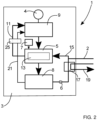
- an energy system 1, 1', 1" according to embodiments of the present invention is schematically illustrated in block diagrams.
- the energy system is arranged to generate and to use thermal energy.
- the energy system 1 comprises a mechanical vapor recompression (MVR) unit 3.
- the MVR-unit 3 comprises a primary heat exchanger 5 arranged to evaporate a working liquid provided to the primary heat exchanger 5.
- the working liquid may be water provided to the primary heat exchanger 5 via a pipe 2 connected to an outer source of working liquid (not shown).
- the MVR-unit comprises a heating unit 7 arranged to heat the working liquid in the primary heat exchanger 5 to initiate the evaporation of the working liquid.
- the heating unit 7 is activated to heat the working liquid in the primary heat exchanger 5.
- the heating unit 7 may be an electric heating unit. In the case of water as the working liquid, water is heated to approximately 85-95 °C by means of the heating unit 7 which is then turned off.
- the MVR-unit comprises a compressor 9 arranged to compress vapor produced in the primary heat exchanger 5 and arranged to deliver the compressed vapor to the primary heat exchanger 5 to evaporate the working liquid in the primary heat exchanger 5.
- the compressor 9 is driven by a motor 4 which is started after the heating unit 7 has initially heated the working liquid in the primary heat exchanger 5.
- the MVR-unit 3 also comprises a primary vapor line 11 arranged in connection to the primary heat exchanger 5 and to the compressor 9 for transport of vapor produced in the primary heat exchanger 5 to the compressor 9. Further, the MVR-unit 3 comprises a condenser 13 arranged to condense the compressed vapor to a condensed working liquid. According to the illustrated embodiments, the condenser 13 is included in the primary heat exchanger 5. Thus, one side or section of the primary heat exchanger 5 will then work as the condenser 13, and another side or section of the primary heat exchanger 5 will work as an evaporator to evaporate the working liquid in the primary heat exchanger 5.
- the primary heat exchanger 5 may comprise a plurality of heat exchanging elements, such as lateral or longitudinal pipes, and the inside of the pipes may then work as the condenser 13, and the outsides of the pipes may work as the evaporator, or opposite around; the outsides of the pipes may then work as the condenser 13, and the inside of the pipes may work as the evaporator.
- This embodiment will be described in details in relation to figure 4 .
- the heating unit 7 is disengaged, and the compressor 9 is engaged.
- the compressor 9 As the compressor 9 starts, it lowers the pressure in the inlet manifold to the compressor 9 to slightly under ambient pressure, which propagates to the primary heat exchanger 5 connected to the compressor 9 via the primary vapor line 11, slightly lowering its pressure to slightly under ambient pressure.
- This pressure decrease enables the boiling of water (and subsequently production of steam) below 100 °C.
- steam forms readily below 95 °C, it gets compressed by the compressor 9 and elevated, by the inserted pressure/volume work, to a temperature of approximately 120 °C with comparably little effort, in this described exemplary situation.
- the superheated steam is then lead to the primary heat exchanger 5 for evaporation of water in the primary heat exchanger.
- the MVR-unit 3 comprises at least one liquid line 15, 15', 15" arranged in connection to the condenser 13 of the primary heat exchanger 5 for transport of the condensed working liquid, and for delivery of the thermal energy of the working liquid to external consumers, and back to the primary heat exchanger 5, specifically back to the evaporator side or section of the primary heat exchanger 5, for re-evaporation in the primary heat exchanger 5.
- the MVR-unit 3 comprises a pump 6 arranged on the liquid line 15, 15', 15" to pump the working liquid via external thermal energy consumers to the primary heat exchanger 5.
- the MVR-unit 3 comprises one liquid line.
- the MVR-unit comprises a collection compartment 8 arranged in connection to the condenser 13 for collecting the condensed working liquid and vapors that have not been condensed.
- the collection compartment 8 arranged in connection to the condenser 13 for collecting the condensed working liquid and vapors that have not been condensed.
- liquid line 15, 15', 15" is connected to the collection compartment 8.
- the liquid line may be directly connected to the condenser 13 of the primary heat exchanger 5.
- the working liquid is arranged, according to the illustrated embodiments, to circulate in a closed loop. This enables a very efficient energy recuperation of the energy system 1, which is beneficial for the external thermal energy outtake from the at least one liquid line.
- the pipe 2 may be connected to the liquid line 15, 15', 15". However, the pipe 2 may be directly connected to the primary heat exchanger 5.
- the energy system 1 also comprises at least one secondary heat exchanger 17 arranged for heat exchange between the working liquid flowing in the liquid line 15 and an external working fluid flowing in at least one external fluid line 19 to use thermal energy generated by the MVR-unit 3.
- one secondary heat exchanger 17 and one external fluid line 19 is used.
- the external working fluid may be a liquid and/or a gas.
- water and/or air can be used as the external working fluid.
- the energy system 1 comprises the secondary heat exchanger 17 arranged for heat exchange between the working liquid flowing in the liquid line 15 and an external working fluid flowing in an external fluid line 19 the thermal energy generated by the MVR-unit 3 will be used in an efficient way. Firstly, be transferring the thermal energy from the working liquid to the external working fluid, and secondly by using the external working fluid directly in an external system (not shown), such as an energy system or industrial system, and/or by heat exchanging the external working fluid with an additional working fluid of an external system.
- an external system not shown
- the liquid line 15 and the secondary heat exchanger 17 of the energy system 1 are comprised by the MVR-unit 3.
- the MVR-unit 3 may be provided to the intended location of use and then connected to an external system by the external liquid line 19 connected to the secondary heat exchanger 17.
- the energy system 1 may comprise at least one secondary vapor line 21.
- the MVR-unit 3 comprises one secondary vapor line 21 arranged in connection to the condenser 13 and to the compressor 9 for transport of the compressed vapor from the condenser 13 to the compressor 9.
- the MVR-unit 3 may be provided with a collection compartment 8 arranged in connection to the condenser 13 for collecting the condensed working liquid and vapors that have not been condensed.
- the secondary vapor line 21 is then connected to the collection compartment 8.
- an energy system 1 is provided where the uncondensed compressed vapor can be used.
- the compressed vapor are then, which is advantageous, transported to a higher compression stage of the compressor 9 than the vapor transported through the primary vapor line 11.
- the MVR-unit 3 may comprise a separator 25 arranged in connection to the compressor 9 and arranged to separate droplets in the vapor transported to the compressor 9.
- the separator 25 is arranged on the primary vapor line 11 and on the secondary vapor line 21.
- the energy system 1 comprises a control system (not shown) arranged to monitor and to control the process of the MVR-unit and of the entire energy system regarding the pressure, temperature, flow ratio, compressor and pump performances together with other influential parameters of the system.
- an energy system 1' is schematically illustrated in a block diagram.
- the energy system 1' is arranged to generate and to use thermal energy generated by a MVR-unit 3 in a similar way as the energy system 1 described in relation to figure 2 .
- the energy system 1' has the same technical features and advantages as the corresponding features of the energy system 1 described above. Consequently, these technical features and advantages are not repeated or explained anew in order to avoid unnecessary repetition.
- the secondary heat exchanger 17 of the energy system 1' is arranged outside the MVR-unit 3.
- the MVR-unit 3 may be provided to the intended location of use, where the secondary heat exchanger 17 and the external liquid line 19 have been prepared, and then may be connected to an external system by connection of the liquid line 15' of the MVR-unit 3 to the secondary heat exchanger 17.
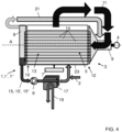
- FIG 4 is a schematic illustration of the energy system 1, 1', 1" illustrated in figures 1-3 according to some more specific embodiments.
- the MVR-unit 3 comprises a common pressure-tight enclosure 23 having a substantially circular cylindrical elongated shape along a longitudinal axis A.
- Many other shapes of the pressure-tight enclosure is naturally possible, e.g. enclosures having rectangular, elliptical, triangular, hexagonal, and other more complex cross-sectional shapes.
- FIG 4 a compact design of the MVR-unit 3 is illustrated.
- the compact design of the MVR-unit 3 is achieved, inter alia because the primary heat exchanger 5, the compressor 9, and the condenser 13, which is a part of the primary heat exchanger 5, are arranged within the common pressure-tight enclosure 23.
- the common pressure-tight enclosure 23 is provided with a first end 10, and with a second end 12, and wherein the secondary vapor line 21 is arranged at the first end 10 of the common pressure-tight enclosure 23 and the compressor 9 is arranged at the second end 12 of the common pressure-tight enclosure 23.
- the first end 10 and the second end 12 are opposite ends of the common pressure-tight enclosure 23 along the longitudinal axis A.
- the primary heat exchanger 5 comprises a plurality of longitudinal pipes 14. As illustrated in figure 4 , the longitudinal pipes 14 are arranged horizontally along the longitudinal axis A.
- the compressed vapor from the compressor 9 are provided into the inside of each pipe of the plurality of longitudinal pipes 14 to evaporate the working liquid provided to the outside of each pipe of the plurality of longitudinal pipes 14.
- the superheated steam from the compressor 9 is provided through the inside of the horizontal set of pipes consisting of the plurality of the pipes 14, e.g. longitudinal pipes, that are submerged in an operating medium, i.e. in the working liquid.
- the pipes 14 are submerged in a denser medium of lower temperature than the steam from the compressor 9.
- the insides of the pipes 14 of the primary heat exchanger 5 work as the condenser 13 and the outsides of the pipes14 work as evaporator, and as disclosed above, the opposite, i.e. that the outsides of the pipes may then work as the condenser 13, and the inside of the pipes may work as the evaporator.
- the longitudinal pipes are not submerged into the working liquid. Instead, the working liquid is dispersed evenly onto the pipes e.g. sprayed onto via spraying nozzles. This is advantageous regarding the steam production flow rate.
- a secondary heat exchanger 17 is provided at the liquid line 15, for heat exchanging thermal energy from the working liquid flowing in the liquid line to an external fluid line 19.
- the secondary heat exchanger 17, and the external fluid line 19 are not included and the liquid line 15 is instead directly arranged to provide thermal energy from the working liquid to any outside consumer.
- the present invention also relates to a method for using thermal energy generated by a mechanical vapor recompression (MVR) unit 3 of an energy system 1, 1', 1".
- MVR mechanical vapor recompression
- a method of an energy system where the energy system 1, 1', 1" comprises a mechanical vapor recompression (MVR) unit 3.
- the method comprises utilizing externally said energy system, thermal energy of a working liquid obtained during an MVR process performed by said MVR unit, preferably for heating processes, spaces or objects.
- the energy system 1, 1', 1" comprises at least one liquid line 15" where the working liquid flows
- the method comprises arranging the at least one liquid line in a configuration outside the energy system, preferably in a closed loop configuration, and providing it to energy consumers for any applicable use.
- the method comprises heat exchanging the working liquid with an external working fluid to use thermal energy generated by the MVR-unit 3.
Landscapes
- Engineering & Computer Science (AREA)
- Physics & Mathematics (AREA)
- Mechanical Engineering (AREA)
- Thermal Sciences (AREA)
- General Engineering & Computer Science (AREA)
- Chemical & Material Sciences (AREA)
- Chemical Kinetics & Catalysis (AREA)
- Vaporization, Distillation, Condensation, Sublimation, And Cold Traps (AREA)
Abstract
Description
- The present disclosure relates to an energy system comprising a mechanical vapor recompression (MVR) unit and to a method for using thermal energy generated by the MVR-unit. More particularly, the energy system and the method are arranged to utilize thermal energy generated by the MVR-unit for use externally of the energy system, e.g. for processes and objects outside of the energy system.
- Mechanical vapor recompression (MVR) or mechanical vapor compression (MVC) are two similar methods applying pressure/volume work to water vapor, in order to increase its enthalpy thereby superheating the steam. The rationale behind is that heating already formed vapor costs comparatively little energy comparing to generating new pristine vapor. In order to successfully enable the recuperation of the evaporation heat, which constitutes the majority of the heat into the system, a positive and significant temperature difference between the superheated steam and the recipient medium, driving the re-flux of energy in the reverse direction, is needed to become established. This is the main reason for steam (re)compression.
- An MVR-unit usually comprises an evaporator, where the evaporation of a working medium takes place, a condenser, where the condensation takes place, a compressor that compresses the steam from the evaporator to a superheated state, a heating unit for initiating the evaporation process in the evaporator, and a control system that monitors and controls the process.
- Below some patent documents within the technical field of MVR will be briefly discussed.
- In the
EP2716341 a system and a method is described for liquid treatment by mechanical vapor recompression comprising a fixed fluid-tight evaporator housing with improved characteristics regarding the heat exchange between heated vapor-containing volume and recompressed heating vapor-containing volume. -
WO2022/089827 describes a process water distillation plant comprising a control device arranged to control the supply of energy from an energy source into the process water distillation plant depending on the progress of the distillation process in the process water distillation plant. - In the
EP3689449 a system for energy recycling using mechanical vapor recompression in combined chemical process is described. -
WO2022/243287 describes a robust mechanical vapor recompression arrangement comprising a compound turbine system. - The above mentioned documents describe systems and methods where mechanical vapor recompression are used. However, by applying their detailed knowledge of MVR, the inventors have identified and realized further applications and utilizations of the MVR-technology, not presently known.
- The object of the present invention is to use the heat generating capabilities that the processes Mechanical Vapor Recompression (MVR) and Mechanical Vapor Compression (MVC) utilize and possess. These said, already known, processes utilize the fact that compression of water vapor (steam) leads to an increase of temperature of the compressed steam. In energy terminology; the increase of thermal energy, of the steam, exceeds the energy needed to induce the necessary pressure/volume work of the said steam. In other words; the coefficient of performance (COP) or ratio between heat generation to energy insertion, of the steam/compression work, exceeds unity. As discussed above, this has already been used today as a way to treat water in a evaporation-vapor compression-condensation loop, e.g. in desalination, whereby the heated steam leads water to boil and evaporate.
- However, the applications of the said processes are most often desalination or purification of contaminated water. Since the process involves boiling, evaporation and condensation, the condensate is both pure and desalinated. Besides, it is also hot (around 100 °C if the process takes place in atmospheric pressure). To date, the relatively high temperature of the condensate has not been utilized as a primary result of the process. Rather, the high temperature of the condensate has historically always been used to pre-heat the working liquid, to become treated in the MVR process, in an effort to increase the internal efficiency of the MVR/MVC processes.
- The inventors have realized a further and a very beneficial application of the MVR-technology. The core of the present invention is that no-one has previously used the hot temperature working liquid, in particular the condensate of the working liquid, (typically 100 °C), for heating purposes of external objects or spaces, such as buildings, or in heat consuming industrial processes such as absorption chilling. In other words, the uniqueness of the energy system and method according to the present invention, is to utilize the MVR/MVC process as a way to generate hot working liquid which is used to heat external objects or spaces (such as buildings or industrial processes), and not, as in the above discussed known applications of the MVR-technology, to increase the internal efficiency of the MVR/MVC process.
- An essential aspect of the present invention, as defined by the independent claims, is the focus on utilization of heat and not the pure condensate as such. Although it is technically possible, it is not a primarily interest to tap off the condensed water. Therefore, it is advantageous for the process to run in a "closed loop", whereby the working liquid, after exchanging parts (or the entirety) of its heat energy to an external object such as a building, via a heat exchanger or directly, goes back into the MVR process. However, as mentioned above, one could also imagine where parts of the working liquid is tapped off for particular reasons, and utilized as hot, desalinated water, although this, unlike the closed loop process, requires new water (or any other liquid used in the process) to be added to the process. For most purposes of heating of industrial processes or buildings, e.g. district heating, and heating of individual houses, this is neither desired, nor practical, so therefore, the solution defined by the appended claims primarily utilizes a closed loop.
- Thus, it is worth emphasizing that the object of the present invention and the primary goal for the claimed energy system and method is to produce a working liquid (preferably hot water) with high efficiency, for external use.
- The working fluid resulting from the MVR/MVC process is particularly suitable for heating purposes since it consists of distilled and desalinated water with low corrosivity - a necessary prerequisite for heating systems since radiators, heat exchangers and transportation pipelines are usually ferrous. The solution provides thus a new use of the MVR-technology, as a way to generate e.g. hot water of suitable quality, for the purpose that generated hot water releases part of its energy to external processes and objects, e.g. buildings, e.g. for heating purposes.
- The above object is achieved by the energy system and the method according to the independent claims.
- Preferred embodiments are set forward by the dependent claims.
- According to a first aspect of the invention, the object is achieved by an energy system according to
claim 1. Thus, the invention relates to an energy system arranged to generate and to use thermal energy, where the energy system comprises a mechanical vapor recompression (MVR) unit, wherein thermal energy of a working liquid obtained during an MVR process performed by the MVR unit is utilized externally of the energy system, preferably for heating processes or objects. - Although specific examples are disclosed herein regarding obtaining energy, in particular from condensate of the working liquid, it should be noted that thermal energy may be obtained from the working liquid throughout the entire MVR process, e.g. from the working liquid in a boiling or heated state.
- In one embodiment, the energy system comprises at least one liquid line where the working liquid flows. This, at least one, liquid line is arranged in a configuration outside the energy system, preferably in a closed loop configuration, and provides energy to consumers for applicable use. In this embodiment no heat exchanger (neither arranged inside nor outside of the energy system) is required instead the working liquid, flowing in the at least one liquid line, carries the thermal energy generated by the MVR-unit, to the energy consumers, by itself, and, preferably, returns to the energy system in a closed loop configuration. This is advantageous as it probably provides the highest energy transfer efficiency a MVR-process can produce. A closed loop configuration is often preferred, however, there are applications where parts of the working liquid may be tapped off from the liquid line and used, e.g. if hot water is needed. In that case a pipe is provided to replace the tapped off volume of the working liquid.
- In another embodiment, the energy system comprises at least one secondary heat exchanger arranged for heat exchange between the condensed working liquid flowing in an at least one liquid line and an external working fluid (i.e. a gas or a liquid) flowing in an at least one external fluid line to use thermal energy generated by the MVR-unit. In this embodiment, the condensed working liquid flows in a separate closed loop configuration. This is advantageous as it provides a highly efficient and flexible MVR-process.
- According to an embodiment, the energy system comprises a mechanical vapor recompression MVR unit comprising:
- a primary heat exchanger, arranged to evaporate a working liquid provided to the primary heat exchanger;
- a compressor arranged to compress vapor produced in the primary heat exchanger and arranged to deliver the compressed vapor to the primary heat exchanger to evaporate the working liquid in the primary heat exchanger;
- at least one primary vapor line arranged in connection to the primary heat exchanger and to the compressor for transport of vapor produced in the primary heat exchanger to the compressor, and
- a condenser arranged to condense the compressed vapor to a condensed working liquid.
- In a further embodiment, the MVR-unit comprises at least one liquid line arranged in connection to the condenser and via an external thermal energy consumer to the primary heat exchanger for transport of the working liquid back to the primary heat exchanger for re-evaporation in the primary heat exchanger. Because the at least one liquid line is arranged in connection to the condenser and to the primary heat exchanger for transport of the condensed working liquid back to the primary heat exchanger for re-evaporation in the primary heat exchanger, the working liquid is arranged to circulate in a closed loop. The condensed working liquid, having transferred some of its energy to the external heat consumer, is transported back to the primary heat exchanger in a closed loop, substantially with no mass losses. This enables a new way of efficient energy recuperation since less energy is needed to evaporate the working liquid circulating in a closed loop comparing to the known systems.
- The working liquid circulating in a closed loop is an advantageous design of an MVR-unit because historically, in one application, the MVR technology has been used to produce desalinated and distilled water for e.g. drinking purposes or industrial purposes, where the condensed working liquid (that can be water) has been used as a product from MVR. The closed loop arrangement of the working liquid enables use of the MVR-unit as a high-efficient producer of thermal energy to be used outside the MVR-unit. According to one embodiment, the condensed working liquid is not sent out as it is done according to previous solutions, e.g. to produce drinking water or purified water for industrial applications, but is essentially reused in the primary heat exchanger.
- In one embodiment, the energy system comprises at least one secondary heat exchanger arranged for heat exchange between the condensed working liquid flowing in the at least one liquid line and the external working fluid flowing in the at least one external fluid line Thus, the thermal energy generated by the MVR-unit according to the present invention is used in an efficient way. Firstly, by transferring the thermal energy to the external working fluid, and secondly, by using the external working fluid directly in an external system, such as an energy system or industrial system, and/or by heat exchanging and/or mixing the external working fluid with an additional working fluid from an external system.
- There are no limitations regarding the external system that can utilize thermal energy generated by the MVR-unit. Any systems where thermal energy from a liquid or gas carrier is of interest, can be connected to the MVR-unit. For example, thermal energy generated by the MVR-unit can be used in district heating, for heating of buildings, as energy storage, for industrial processes or similar, but also in airborne heating systems via an liquid to air heat exchanger.
- A further advantage of the system according to present invention is that the energy system with the MVR-unit may be located at the desired location for utilization of thermal energy generated by the MVR-unit. The energy system with the MVR-unit may be arranged as a mobile system.
- In one further embodiment, the MVR-unit comprises a common pressure-tight enclosure and wherein at least the primary heat exchanger and the condenser are arranged within the common pressure-tight enclosure. Thus, a compact-design MVR-unit is provided enabling arranging at least the primary heat exchanger and the condenser within the common pressure-tight enclosure. Mobility of the MVR-unit and of the energy system is thereby improved. Further, risk for leakage between the primary heat exchanger and the condenser is reduced.
- According to a second aspect of the invention the object is achieved by a method according to the independent method claim.
- Thus, the object is achieved by a method of an energy system for using thermal energy generated by a mechanical vapor recompression (MVR) unit. The method comprises utilizing externally said energy system, thermal energy of a working liquid obtained during an MVR process performed by the MVR-unit, preferably for heating processes or objects.
- In one embodiment, the energy system comprises at least one liquid line where the working liquid flows, and the method comprises arranging the at least one liquid line in a configuration outside the energy system, preferably in a closed loop configuration, and providing it to energy consumers for any applicable use.
- This is advantageous as it probably provides the highest energy transfer efficiency a MVR-process can produce, as no external heat exchanging is required, and thus, the thermal energy of the working liquid may be efficiently obtained.
- In another embodiment, the method comprises heat exchanging the condensed working liquid with an external working fluid to use thermal energy generated by the MVR-unit. Because, according to this embodiment, the working liquid is transported back to the primary heat exchanger for re-evaporation in the primary heat exchanger, the working liquid is arranged to circulate in a closed loop. The condensed working liquid, deprived by external energy consumer of some of its energy, is transported back to the primary heat exchanger in a closed loop, substantially with no mass losses. This enables a new way of efficient energy recuperation since less energy is needed to evaporate the working liquid circulating in a closed loop comparing to the known systems.
- By circulating the working liquid in a closed loop, according to an embodiment of the present invention, an advantageous design of an MVR-unit is achieved, because historically, as discussed above, the MVR technology has been used to produce drinking water, or purified water for industrial purposes, where the condensed working liquid has been used as a product from MVR, i.e. fresh drinking water. This newly introduced closed loop arrangement, of the working liquid, now also enables the use of the MVR-unit as a high-efficient producer of thermal energy to become utilised outside the MVR-unit explicitly for external thermal energy transfer processes. According to the one embodiment of the present invention the working liquid is not sent out as it is done according to previous solutions, e.g. to produce drinking water, but is completely reused in the primary heat exchanger.
- Further, because the method preferably comprises the step of heat exchanging the working liquid with the external working fluid to use thermal energy generated by the MVR-unit, the thermal energy generated by the MVR-unit according to the present invention is used in an efficient way. Firstly, by transferring the thermal energy to the external working fluid, and secondly by using the external working fluid directly in an external system, such as an energy system or industrial system, and/or by heat exchanging the external working fluid with an additional working fluid of an external system.
- There are no limitation regarding the external system that can utilize thermal energy generated by the MVR-unit. Any systems where thermal energy from a liquid or gas carrier is of interest, can be connected to the MVR-unit. For example, thermal energy generated by the MVR-unit can be used in district heating, for heating of buildings, as energy storage, for industrial and other technical processes or similar, and liquid to liquid heat exchanging or liquid to air heat exchanging.
- Preferably, the working liquid is water, and the external working fluid is a liquid and/or a gas. Thus, for example oil, water or air can be used as the external working fluid.
- Accordingly, a method for using thermal energy generated by a mechanical vapor recompression (MVR) unit is provided and thereby the above-mentioned object is achieved.
-
-
Fig. 1 is a block diagram schematically illustrating an energy system comprising an MVR-unit according to an embodiment of the invention. -
Fig. 2 is a block diagram schematically illustrating an energy system comprising an MVR-unit according to another embodiment of the invention. -
Fig. 3 is a block diagram schematically illustrating an energy system comprising an MVR-unit according to a further embodiment of the invention. -
Fig. 4 is a schematic illustration of the energy system illustrated inFig. 1 andFig. 2 according to some embodiments. -
Fig. 5 is a flow diagram illustrating a method according to the invention. - The energy system will now be described in detail with references to the appended figures. Throughout the figures the same, or similar, items have the same reference signs.
- Moreover, the items and the figures are not necessarily to scale, emphasis instead being placed upon illustrating the principles of the invention.
- In the figures, the arrows illustrate the flow direction in the respective line.
- Within the application the expression working liquid should be interpreted as a working liquid used and obtained during the MVR process, and may then be a condensate of the working liquid, or the working liquid in a boiling or heated state.
- According to the invention, an
energy system unit 3, wherein thermal energy of a working liquid obtained during an MVR process performed by the MVR-unit is utilized externally the energy system, preferably for heating processes, spaces or objects. - According to one embodiment, illustrated by
figure 1 , theenergy system 1" comprises at least oneliquid line 15" where the working liquid flows. The at least one liquid line is arranged in a configuration outside the energy system, preferably in a closed loop configuration, which is illustrated infigure 1 , and provided to energy consumers for any applicable use. The thermal energy provided to the outside energy consumers is schematically indicated by arrows. In a variation of this embodiment, parts of the working liquid are tapped off from the liquid line and used for external purposes, e.g. if hot water is needed. In that case apipe 2 is provided to replace the tapped off volume of the working liquid. - According to embodiments illustrated by
figures 2-4 , theenergy system 1, 1' comprises at least onesecondary heat exchanger 17 arranged for heat exchange between the working liquid flowing in an at least oneliquid line 15, 15' and an external working fluid (liquid or gas) flowing in at least oneexternal fluid line 19 to use thermal energy generated by the MVR-unit 3. - With reference to
figures 1-4 , anenergy system energy system 1 comprises a mechanical vapor recompression (MVR)unit 3. The MVR-unit 3 comprises aprimary heat exchanger 5 arranged to evaporate a working liquid provided to theprimary heat exchanger 5. The working liquid may be water provided to theprimary heat exchanger 5 via apipe 2 connected to an outer source of working liquid (not shown). - Preferably, the MVR-unit comprises a
heating unit 7 arranged to heat the working liquid in theprimary heat exchanger 5 to initiate the evaporation of the working liquid. After the working liquid has been provided to theprimary heat exchanger 5, theheating unit 7 is activated to heat the working liquid in theprimary heat exchanger 5. Theheating unit 7 may be an electric heating unit. In the case of water as the working liquid, water is heated to approximately 85-95 °C by means of theheating unit 7 which is then turned off. - The MVR-unit comprises a
compressor 9 arranged to compress vapor produced in theprimary heat exchanger 5 and arranged to deliver the compressed vapor to theprimary heat exchanger 5 to evaporate the working liquid in theprimary heat exchanger 5. Preferably, thecompressor 9 is driven by amotor 4 which is started after theheating unit 7 has initially heated the working liquid in theprimary heat exchanger 5. - The MVR-
unit 3 also comprises aprimary vapor line 11 arranged in connection to theprimary heat exchanger 5 and to thecompressor 9 for transport of vapor produced in theprimary heat exchanger 5 to thecompressor 9. Further, the MVR-unit 3 comprises acondenser 13 arranged to condense the compressed vapor to a condensed working liquid. According to the illustrated embodiments, thecondenser 13 is included in theprimary heat exchanger 5. Thus, one side or section of theprimary heat exchanger 5 will then work as thecondenser 13, and another side or section of theprimary heat exchanger 5 will work as an evaporator to evaporate the working liquid in theprimary heat exchanger 5. For example, theprimary heat exchanger 5 may comprise a plurality of heat exchanging elements, such as lateral or longitudinal pipes, and the inside of the pipes may then work as thecondenser 13, and the outsides of the pipes may work as the evaporator, or opposite around; the outsides of the pipes may then work as thecondenser 13, and the inside of the pipes may work as the evaporator. This embodiment will be described in details in relation tofigure 4 . - Thus, when the desired temperature is reached (for water, approximately 85-95 °C), the
heating unit 7 is disengaged, and thecompressor 9 is engaged. As thecompressor 9 starts, it lowers the pressure in the inlet manifold to thecompressor 9 to slightly under ambient pressure, which propagates to theprimary heat exchanger 5 connected to thecompressor 9 via theprimary vapor line 11, slightly lowering its pressure to slightly under ambient pressure. This pressure decrease enables the boiling of water (and subsequently production of steam) below 100 °C. As steam forms readily below 95 °C, it gets compressed by thecompressor 9 and elevated, by the inserted pressure/volume work, to a temperature of approximately 120 °C with comparably little effort, in this described exemplary situation. The superheated steam is then lead to theprimary heat exchanger 5 for evaporation of water in the primary heat exchanger. - An essential aspect of the embodiments of the energy system as defined by the appended claims, is that the MVR-
unit 3 comprises at least oneliquid line condenser 13 of theprimary heat exchanger 5 for transport of the condensed working liquid, and for delivery of the thermal energy of the working liquid to external consumers, and back to theprimary heat exchanger 5, specifically back to the evaporator side or section of theprimary heat exchanger 5, for re-evaporation in theprimary heat exchanger 5. Preferably, the MVR-unit 3 comprises apump 6 arranged on theliquid line primary heat exchanger 5. According to the embodiments illustrated in the figures, the MVR-unit 3 comprises one liquid line. - According to the embodiments illustrated in the figures the MVR-unit comprises a
collection compartment 8 arranged in connection to thecondenser 13 for collecting the condensed working liquid and vapors that have not been condensed. Thus, collecting of the condensed working liquid and vapor that has not been condensed is facilitated by thecollection compartment 8. - Further, according to the illustrated embodiments the
liquid line collection compartment 8. However, as an alternative variation, the liquid line may be directly connected to thecondenser 13 of theprimary heat exchanger 5. - Because the
liquid line 15 in the embodiments illustrated infigures 1-4 is arranged in connection to thecollection compartment 8 or possibly directly to thecondenser 13 and to theprimary heat exchanger 5 for transport of the condensed working liquid back to theprimary heat exchanger 5 for re-evaporation in theprimary heat exchanger 5, the working liquid is arranged, according to the illustrated embodiments, to circulate in a closed loop. This enables a very efficient energy recuperation of theenergy system 1, which is beneficial for the external thermal energy outtake from the at least one liquid line. - As illustrated in
figures 1-4 , thepipe 2 may be connected to theliquid line pipe 2 may be directly connected to theprimary heat exchanger 5. - According to one embodiment, the
energy system 1 also comprises at least onesecondary heat exchanger 17 arranged for heat exchange between the working liquid flowing in theliquid line 15 and an external working fluid flowing in at least oneexternal fluid line 19 to use thermal energy generated by the MVR-unit 3. According to the embodiments illustrated infigure 2 , onesecondary heat exchanger 17 and oneexternal fluid line 19 is used. The external working fluid may be a liquid and/or a gas. Thus, for example, water and/or air can be used as the external working fluid. - Because the
energy system 1, according to the embodiments illustrated infigures 2-4 , comprises thesecondary heat exchanger 17 arranged for heat exchange between the working liquid flowing in theliquid line 15 and an external working fluid flowing in anexternal fluid line 19 the thermal energy generated by the MVR-unit 3 will be used in an efficient way. Firstly, be transferring the thermal energy from the working liquid to the external working fluid, and secondly by using the external working fluid directly in an external system (not shown), such as an energy system or industrial system, and/or by heat exchanging the external working fluid with an additional working fluid of an external system. - According to the embodiment of the
energy system 1 illustrated infigure 2 , theliquid line 15 and thesecondary heat exchanger 17 of theenergy system 1 are comprised by the MVR-unit 3. Thus, the MVR-unit 3 may be provided to the intended location of use and then connected to an external system by theexternal liquid line 19 connected to thesecondary heat exchanger 17. - The
energy system 1 may comprise at least onesecondary vapor line 21. According to the embodiments illustrated infigures 1-4 , the MVR-unit 3 comprises onesecondary vapor line 21 arranged in connection to thecondenser 13 and to thecompressor 9 for transport of the compressed vapor from thecondenser 13 to thecompressor 9. As discussed above, the MVR-unit 3 may be provided with acollection compartment 8 arranged in connection to thecondenser 13 for collecting the condensed working liquid and vapors that have not been condensed. Thesecondary vapor line 21 is then connected to thecollection compartment 8. Thus, anenergy system 1 is provided where the uncondensed compressed vapor can be used. The compressed vapor are then, which is advantageous, transported to a higher compression stage of thecompressor 9 than the vapor transported through theprimary vapor line 11. - The MVR-
unit 3 may comprise aseparator 25 arranged in connection to thecompressor 9 and arranged to separate droplets in the vapor transported to thecompressor 9. Preferably, theseparator 25 is arranged on theprimary vapor line 11 and on thesecondary vapor line 21. - The
energy system 1 comprises a control system (not shown) arranged to monitor and to control the process of the MVR-unit and of the entire energy system regarding the pressure, temperature, flow ratio, compressor and pump performances together with other influential parameters of the system. - With reference to
figure 3 , an energy system 1' according to another embodiment, is schematically illustrated in a block diagram. The energy system 1' is arranged to generate and to use thermal energy generated by a MVR-unit 3 in a similar way as theenergy system 1 described in relation tofigure 2 . The energy system 1' has the same technical features and advantages as the corresponding features of theenergy system 1 described above. Consequently, these technical features and advantages are not repeated or explained anew in order to avoid unnecessary repetition. - According to the embodiments illustrated in
figure 3 , thesecondary heat exchanger 17 of the energy system 1' is arranged outside the MVR-unit 3. Thus, the MVR-unit 3 may be provided to the intended location of use, where thesecondary heat exchanger 17 and theexternal liquid line 19 have been prepared, and then may be connected to an external system by connection of the liquid line 15' of the MVR-unit 3 to thesecondary heat exchanger 17. -
Figure 4 is a schematic illustration of theenergy system figures 1-3 according to some more specific embodiments. The MVR-unit 3 comprises a common pressure-tight enclosure 23 having a substantially circular cylindrical elongated shape along a longitudinal axis A. Many other shapes of the pressure-tight enclosure is naturally possible, e.g. enclosures having rectangular, elliptical, triangular, hexagonal, and other more complex cross-sectional shapes. - In
figure 4 , a compact design of the MVR-unit 3 is illustrated. The compact design of the MVR-unit 3 is achieved, inter alia because theprimary heat exchanger 5, thecompressor 9, and thecondenser 13, which is a part of theprimary heat exchanger 5, are arranged within the common pressure-tight enclosure 23. - The common pressure-
tight enclosure 23 is provided with afirst end 10, and with asecond end 12, and wherein thesecondary vapor line 21 is arranged at thefirst end 10 of the common pressure-tight enclosure 23 and thecompressor 9 is arranged at thesecond end 12 of the common pressure-tight enclosure 23. Preferably, thefirst end 10 and thesecond end 12 are opposite ends of the common pressure-tight enclosure 23 along the longitudinal axis A. - The
primary heat exchanger 5 comprises a plurality oflongitudinal pipes 14. As illustrated infigure 4 , thelongitudinal pipes 14 are arranged horizontally along the longitudinal axis A. - The compressed vapor from the
compressor 9 are provided into the inside of each pipe of the plurality oflongitudinal pipes 14 to evaporate the working liquid provided to the outside of each pipe of the plurality oflongitudinal pipes 14. - Thus, the superheated steam from the
compressor 9 is provided through the inside of the horizontal set of pipes consisting of the plurality of thepipes 14, e.g. longitudinal pipes, that are submerged in an operating medium, i.e. in the working liquid. Thepipes 14 are submerged in a denser medium of lower temperature than the steam from thecompressor 9. The insides of thepipes 14 of theprimary heat exchanger 5 work as thecondenser 13 and the outsides of the pipes14 work as evaporator, and as disclosed above, the opposite, i.e. that the outsides of the pipes may then work as thecondenser 13, and the inside of the pipes may work as the evaporator. - In a further variation, the longitudinal pipes are not submerged into the working liquid. Instead, the working liquid is dispersed evenly onto the pipes e.g. sprayed onto via spraying nozzles. This is advantageous regarding the steam production flow rate.
- In the embodiment illustrated in
figure 4 , asecondary heat exchanger 17 is provided at theliquid line 15, for heat exchanging thermal energy from the working liquid flowing in the liquid line to anexternal fluid line 19. However, in another embodiment, similar to the embodiment illustrated infigure 1 , thesecondary heat exchanger 17, and theexternal fluid line 19, are not included and theliquid line 15 is instead directly arranged to provide thermal energy from the working liquid to any outside consumer. - The present invention also relates to a method for using thermal energy generated by a mechanical vapor recompression (MVR)
unit 3 of anenergy system figure 5 . - Thus, a method of an energy system is provided, where the
energy system unit 3. The method comprises utilizing externally said energy system, thermal energy of a working liquid obtained during an MVR process performed by said MVR unit, preferably for heating processes, spaces or objects. - In the following, some embodiments of the method are listed. These have the same technical features and advantages as for the corresponding features of the
energy systems - According to one embodiment, the
energy system liquid line 15" where the working liquid flows, and the method comprises arranging the at least one liquid line in a configuration outside the energy system, preferably in a closed loop configuration, and providing it to energy consumers for any applicable use. - According to another embodiment, the method comprises heat exchanging the working liquid with an external working fluid to use thermal energy generated by the MVR-
unit 3. - The present invention is not limited to the above-described preferred embodiments. Various alternatives, and modifications may be used. Therefore, the above embodiments should not be taken as limiting the scope of the invention, which is defined by the appending claims.
Claims (15)
- An energy system (1, 1', 1") arranged to generate and to use thermal energy, characterized in that the energy system (1, 1', 1") comprises a mechanical vapor recompression (MVR) unit (3), wherein thermal energy of a working liquid obtained during an MVR process performed by said MVR unit (3) is utilized externally said energy system (1, 1', 1"), preferably for heating processes, spaces or objects.
- The energy system (1") according to claim 1, wherein the energy system (1") comprises at least one liquid line (15") where the working liquid flows, and wherein the at least one liquid line (15") is arranged in a configuration outside the energy system, preferably in a closed loop configuration, and provided to energy consumers for any applicable use.
- The energy system (1, 1') according to claim 1 or 2, wherein the energy system (1, 1') comprises at least one secondary heat exchanger (17) arranged for heat exchange between the working liquid flowing in at least one liquid line (15, 15') and an external working fluid flowing in at least one external fluid line (19) to use thermal energy generated by the MVR-unit (3).
- The energy system (1, 1', 1") according to claim 2 or 3, wherein the MVR unit (3) comprises:- a primary heat exchanger (5) arranged to receive:- a working liquid and- compressed vapor,wherein the primary heat exchanger (5) is arranged to produce vapor by evaporation of the working liquid by heat exchanging the working liquid with the compressed vapor in the primary heat exchanger (5);- a compressor (9) arranged to compress vapor produced in the primary heat exchanger (5) and arranged to deliver the compressed vapor to the primary heat exchanger (5) to evaporate the working liquid in the primary heat exchanger (5);- at least one primary vapor line (11) arranged in connection to the primary heat exchanger (5) and to the compressor (9) for transport of vapor produced in the primary heat exchanger (5) to the compressor (9), andwherein said at least one liquid line (15, 15', 15") is arranged in connection to the condenser (13) of the primary heat exchanger 5 for transport of the condensed working liquid, and for delivery of the thermal energy of the working liquid to external consumers, and back to the primary heat exchanger (5), specifically back to an evaporator side or section of the primary heat exchanger (5), for re-evaporation in the primary heat exchanger (5).
- The energy system (1, 1', 1") according to claim 4, wherein the MVR-unit (3) comprises at least one secondary vapor line (21) arranged in connection to the primary heat exchanger (5) and to the compressor (9) for transport of compressed vapor, that has not been condensed in the primary heat exchanger (5) back to the compressor (9).
- The energy system (1, 1', 1") according to any of claims 4 or 5, wherein the MVR-unit (3) comprises a compartment (8) connected to the primary heat exchanger (5) and arranged to collect the condensed compressed vapor from the primary heat exchanger (5) and to collect the compressed vapor, that has not been condensed in the primary heat exchanger (5), wherein the at least one liquid line (15, 15', 15") and/or the at least one secondary vapor line (21) is arranged in connection to the compartment (8).
- The energy system (1, 1', 1") according to any claims 4-6, wherein the MVR-unit (3) comprises a common pressure-tight enclosure (23) and wherein at least the primary heat exchanger (5) is arranged within the common pressure-tight enclosure (23).
- The energy system (1, 1', 1") according to claim 7, wherein the common pressure-tight enclosure (23) is provided with a first end (10) and with a second end (12) and wherein the at least one secondary vapor line (21) is arranged at the first end (10) of the common pressure-tight enclosure (23) and the compressor (9) is arranged at the second end (12) of the common pressure-tight enclosure (23).
- The energy system (1, 1', 1") according to claim 7 or 8, wherein the common pressure-tight enclosure (23) has a substantially cylindrical elongated shape, preferably a circular cylindrical elongated shape, along a longitudinal axis (A).
- The energy system (1, 1', 1") according to any of claims 4-9, wherein the primary heat exchanger (5) comprises a plurality of longitudinal pipes (14).
- The energy system (1, 1', 1") according to claim 10, wherein the compressed vapor from the compressor (9) is provided into the inside of each pipe of the plurality of longitudinal pipes (14) to evaporate the working liquid provided to the outside of each pipe of the plurality of longitudinal pipes (14), or wherein the outsides of the longitudinal pipes work as condenser (13), and the insides of the longitudinal pipes work as evaporator.
- The energy system (1, 1', 1") according to any of the preceding claims, wherein the working liquid is water.
- A method of an energy system (1, 1', 1"), characterized in that the energy system (1, 1') comprises a mechanical vapor recompression (MVR) unit (3), wherein the method comprises utilizing externally said energy system (1, 1'), thermal energy of a working liquid obtained during an MVR process performed by said MVR-unit (3), preferably for heating processes or objects.
- The method according to claim 13, wherein the energy system (1") comprises at least one liquid line (15") where the working liquid flows, and the method comprises arranging the at least one liquid line in a configuration outside the energy system, preferably in a closed loop configuration, and providing it to energy consumers for any applicable use.
- The method according to claim 13 or 14, wherein the method comprises heat exchanging the working liquid with an external working fluid to use thermal energy generated by the MVR-unit (3).
Priority Applications (5)
| Application Number | Priority Date | Filing Date | Title |
|---|---|---|---|
| EP23154203.6A EP4411279B1 (en) | 2023-01-31 | 2023-01-31 | An energy system comprising a mechanical vapor recompression (mvr) unit for using thermal energy generated by the mvr-unit, and a method in relation thereto |
| ES23154203T ES3002282T3 (en) | 2023-01-31 | 2023-01-31 | An energy system comprising a mechanical vapor recompression (mvr) unit for using thermal energy generated by the mvr-unit, and a method in relation thereto |
| HUE23154203A HUE069911T2 (en) | 2023-01-31 | 2023-01-31 | An energy system comprising a mechanical vapor recompression (mvr) unit for using thermal energy generated by the mvr-unit, and a method in relation thereto |
| CN202380091212.2A CN120569599A (en) | 2023-01-31 | 2023-11-14 | Energy systems including Mechanical Vapor Recompression (MVR) units for using thermal energy generated by MVR units and related methods |
| PCT/EP2023/081670 WO2024160401A1 (en) | 2023-01-31 | 2023-11-14 | An energy system comprising a mechanical vapor recompression (mvr) unit for using thermal energy generated by the mvr-unit, and a method in relation thereto |
Applications Claiming Priority (1)
| Application Number | Priority Date | Filing Date | Title |
|---|---|---|---|
| EP23154203.6A EP4411279B1 (en) | 2023-01-31 | 2023-01-31 | An energy system comprising a mechanical vapor recompression (mvr) unit for using thermal energy generated by the mvr-unit, and a method in relation thereto |
Publications (3)
| Publication Number | Publication Date |
|---|---|
| EP4411279A1 true EP4411279A1 (en) | 2024-08-07 |
| EP4411279B1 EP4411279B1 (en) | 2024-10-23 |
| EP4411279C0 EP4411279C0 (en) | 2024-10-23 |
Family
ID=85150759
Family Applications (1)
| Application Number | Title | Priority Date | Filing Date |
|---|---|---|---|
| EP23154203.6A Active EP4411279B1 (en) | 2023-01-31 | 2023-01-31 | An energy system comprising a mechanical vapor recompression (mvr) unit for using thermal energy generated by the mvr-unit, and a method in relation thereto |
Country Status (5)
| Country | Link |
|---|---|
| EP (1) | EP4411279B1 (en) |
| CN (1) | CN120569599A (en) |
| ES (1) | ES3002282T3 (en) |
| HU (1) | HUE069911T2 (en) |
| WO (1) | WO2024160401A1 (en) |
Cited By (1)
| Publication number | Priority date | Publication date | Assignee | Title |
|---|---|---|---|---|
| EP4733686A1 (en) | 2024-10-25 | 2026-04-29 | Aquafair AB | Mechanical vapour recompression (mvr) heating system |
Citations (6)
| Publication number | Priority date | Publication date | Assignee | Title |
|---|---|---|---|---|
| WO1997040327A1 (en) * | 1996-04-25 | 1997-10-30 | The Chugoku Electric Power Co., Inc. | Compression absorption heat pump |
| EP2716341A1 (en) | 2012-10-05 | 2014-04-09 | VITO NV (Vlaamse Instelling voor Technologisch Onderzoek NV) | Device and method for liquid treatment by mechanical vapor recompression |
| CN105363227A (en) * | 2015-12-02 | 2016-03-02 | 中国科学院理化技术研究所 | Mechanical vapor recompression system and mechanical vapor recompression method based on same |
| EP3689449A1 (en) | 2017-09-29 | 2020-08-05 | Sunteco Limited | System for energy regeneration using mechanical vapor recompression in combined chemical process |
| WO2022089827A1 (en) | 2020-11-02 | 2022-05-05 | KMU LOFT Cleanwater GmbH | Process water distillation plant and method for operating a process water distillation plant |
| WO2022243287A1 (en) | 2021-05-19 | 2022-11-24 | Aquafair Ab | Mechanical vapor recompression arrangement |
-
2023
- 2023-01-31 HU HUE23154203A patent/HUE069911T2/en unknown
- 2023-01-31 ES ES23154203T patent/ES3002282T3/en active Active
- 2023-01-31 EP EP23154203.6A patent/EP4411279B1/en active Active
- 2023-11-14 CN CN202380091212.2A patent/CN120569599A/en active Pending
- 2023-11-14 WO PCT/EP2023/081670 patent/WO2024160401A1/en not_active Ceased
Patent Citations (6)
| Publication number | Priority date | Publication date | Assignee | Title |
|---|---|---|---|---|
| WO1997040327A1 (en) * | 1996-04-25 | 1997-10-30 | The Chugoku Electric Power Co., Inc. | Compression absorption heat pump |
| EP2716341A1 (en) | 2012-10-05 | 2014-04-09 | VITO NV (Vlaamse Instelling voor Technologisch Onderzoek NV) | Device and method for liquid treatment by mechanical vapor recompression |
| CN105363227A (en) * | 2015-12-02 | 2016-03-02 | 中国科学院理化技术研究所 | Mechanical vapor recompression system and mechanical vapor recompression method based on same |
| EP3689449A1 (en) | 2017-09-29 | 2020-08-05 | Sunteco Limited | System for energy regeneration using mechanical vapor recompression in combined chemical process |
| WO2022089827A1 (en) | 2020-11-02 | 2022-05-05 | KMU LOFT Cleanwater GmbH | Process water distillation plant and method for operating a process water distillation plant |
| WO2022243287A1 (en) | 2021-05-19 | 2022-11-24 | Aquafair Ab | Mechanical vapor recompression arrangement |
Non-Patent Citations (1)
| Title |
|---|
| HE W F ET AL: "Performance analysis of the mechanical vapor compression desalination system driven by an organic Rankine cycle", ENERGY, ELSEVIER, AMSTERDAM, NL, vol. 141, 5 October 2017 (2017-10-05), pages 1177 - 1186, XP085312089, ISSN: 0360-5442, DOI: 10.1016/J.ENERGY.2017.10.014 * |
Cited By (1)
| Publication number | Priority date | Publication date | Assignee | Title |
|---|---|---|---|---|
| EP4733686A1 (en) | 2024-10-25 | 2026-04-29 | Aquafair AB | Mechanical vapour recompression (mvr) heating system |
Also Published As
| Publication number | Publication date |
|---|---|
| WO2024160401A1 (en) | 2024-08-08 |
| EP4411279B1 (en) | 2024-10-23 |
| CN120569599A (en) | 2025-08-29 |
| EP4411279C0 (en) | 2024-10-23 |
| ES3002282T3 (en) | 2025-03-06 |
| HUE069911T2 (en) | 2025-04-28 |
Similar Documents
| Publication | Publication Date | Title |
|---|---|---|
| Al-Juwayhel et al. | Analysis of single-effect evaporator desalination systems combined with vapor compression heat pumps | |
| US3243359A (en) | Closed-circuit thermal power plant with waste-heat utilization in a distillation plant | |
| CA1140888A (en) | Energy conversion method and system | |
| US4420373A (en) | Energy conversion method and system | |
| KR860001490B1 (en) | A system and method for distilling brine to obtain fresh water | |
| US20210283525A1 (en) | Low energy ejector desalination system | |
| US20060130487A1 (en) | System for augmented electric power generation with distilled water output | |
| CN103806964A (en) | Method and system for comprehensively utilizing steam turbine dead steam latent heat | |
| US4224796A (en) | Method for converting heat energy to mechanical energy with 1,2-dichloro-1,1-difluoroethane | |
| AU2019406286B2 (en) | Heat pump apparatus and district heating network comprising a heat pump apparatus | |
| EP4411279A1 (en) | An energy system comprising a mechanical vapor recompression (mvr) unit for using thermal energy generated by the mvr-unit, and a method in relation thereto | |
| US20260126220A1 (en) | An energy system comprising a mechanical vapor recompression (mvr) unit for using thermal energy generated by the mvr-unit, and a method in relation thereto | |
| CN118270872B (en) | Multi-effect desalination system | |
| WO2019083416A1 (en) | Water desalination system | |
| CN104603554A (en) | Heat exchanger facility | |
| Wu et al. | Analysis of an evaporator-condenser-separated mechanical vapor compression system | |
| DE102006008600A1 (en) | Method for operating of heat-powered unit by means of fluid medium conveyed in pressurised unit | |
| CN118005123A (en) | A multi-effect heat exchange vacuum evaporator | |
| US3883400A (en) | System for thermal desalting of water | |
| CN205351847U (en) | Utilize device of low level heat energy production refrigerated water | |
| JPH0952083A (en) | Seawater desalination equipment | |
| CN106335952A (en) | Device and method for utilizing organic steam to drive multi-effect evaporator to treat salt-containing sewage | |
| JPH05332633A (en) | Composite freezer device | |
| CN117342638B (en) | Vacuum distillation wastewater treatment system | |
| EP4141222A1 (en) | An energy system comprising a mechanical vapor compression (mvc/mvr) subsystem and a method for converting of energy |
Legal Events
| Date | Code | Title | Description |
|---|---|---|---|
| PUAI | Public reference made under article 153(3) epc to a published international application that has entered the european phase |
Free format text: ORIGINAL CODE: 0009012 |
|
| STAA | Information on the status of an ep patent application or granted ep patent |
Free format text: STATUS: REQUEST FOR EXAMINATION WAS MADE |
|
| 17P | Request for examination filed |
Effective date: 20231012 |
|
| AK | Designated contracting states |
Kind code of ref document: A1 Designated state(s): AL AT BE BG CH CY CZ DE DK EE ES FI FR GB GR HR HU IE IS IT LI LT LU LV MC ME MK MT NL NO PL PT RO RS SE SI SK SM TR |
|
| GRAP | Despatch of communication of intention to grant a patent |
Free format text: ORIGINAL CODE: EPIDOSNIGR1 |
|
| STAA | Information on the status of an ep patent application or granted ep patent |
Free format text: STATUS: GRANT OF PATENT IS INTENDED |
|
| RIC1 | Information provided on ipc code assigned before grant |
Ipc: B01D 1/16 20060101ALI20240801BHEP Ipc: F25B 39/00 20060101ALI20240801BHEP Ipc: F25B 30/00 20060101ALI20240801BHEP Ipc: F24D 3/18 20060101ALI20240801BHEP Ipc: B01D 1/28 20060101ALI20240801BHEP Ipc: F25B 1/00 20060101AFI20240801BHEP |
|
| GRAS | Grant fee paid |
Free format text: ORIGINAL CODE: EPIDOSNIGR3 |
|
| INTG | Intention to grant announced |
Effective date: 20240819 |
|
| GRAA | (expected) grant |
Free format text: ORIGINAL CODE: 0009210 |
|
| STAA | Information on the status of an ep patent application or granted ep patent |
Free format text: STATUS: THE PATENT HAS BEEN GRANTED |
|
| AK | Designated contracting states |
Kind code of ref document: B1 Designated state(s): AL AT BE BG CH CY CZ DE DK EE ES FI FR GB GR HR HU IE IS IT LI LT LU LV MC ME MK MT NL NO PL PT RO RS SE SI SK SM TR |
|
| RAP3 | Party data changed (applicant data changed or rights of an application transferred) |
Owner name: AQUAFAIR AB |
|
| REG | Reference to a national code |
Ref country code: GB Ref legal event code: FG4D |
|
| REG | Reference to a national code |
Ref country code: CH Ref legal event code: EP |
|
| REG | Reference to a national code |
Ref country code: DE Ref legal event code: R096 Ref document number: 602023000777 Country of ref document: DE |
|
| REG | Reference to a national code |
Ref country code: IE Ref legal event code: FG4D |
|
| U01 | Request for unitary effect filed |
Effective date: 20241028 |
|
| P04 | Withdrawal of opt-out of the competence of the unified patent court (upc) registered |
Free format text: CASE NUMBER: APP_59925/2024 Effective date: 20241105 |
|
| U07 | Unitary effect registered |
Designated state(s): AT BE BG DE DK EE FI FR IT LT LU LV MT NL PT RO SE SI Effective date: 20241108 |
|
| U20 | Renewal fee for the european patent with unitary effect paid |
Year of fee payment: 3 Effective date: 20250115 |
|
| REG | Reference to a national code |
Ref country code: SK Ref legal event code: T3 Ref document number: E 45690 Country of ref document: SK |
|
| PGFP | Annual fee paid to national office [announced via postgrant information from national office to epo] |
Ref country code: HU Payment date: 20250131 Year of fee payment: 3 |
|
| REG | Reference to a national code |
Ref country code: ES Ref legal event code: FG2A Ref document number: 3002282 Country of ref document: ES Kind code of ref document: T3 Effective date: 20250306 |
|
| PG25 | Lapsed in a contracting state [announced via postgrant information from national office to epo] |
Ref country code: IS Free format text: LAPSE BECAUSE OF FAILURE TO SUBMIT A TRANSLATION OF THE DESCRIPTION OR TO PAY THE FEE WITHIN THE PRESCRIBED TIME-LIMIT Effective date: 20250223 Ref country code: HR Free format text: LAPSE BECAUSE OF FAILURE TO SUBMIT A TRANSLATION OF THE DESCRIPTION OR TO PAY THE FEE WITHIN THE PRESCRIBED TIME-LIMIT Effective date: 20241023 |
|
| PGFP | Annual fee paid to national office [announced via postgrant information from national office to epo] |
Ref country code: ES Payment date: 20250203 Year of fee payment: 3 |
|
| PGFP | Annual fee paid to national office [announced via postgrant information from national office to epo] |
Ref country code: IE Payment date: 20250116 Year of fee payment: 3 |
|
| PGFP | Annual fee paid to national office [announced via postgrant information from national office to epo] |
Ref country code: NO Payment date: 20250127 Year of fee payment: 3 |
|
| PG25 | Lapsed in a contracting state [announced via postgrant information from national office to epo] |
Ref country code: GR Free format text: LAPSE BECAUSE OF FAILURE TO SUBMIT A TRANSLATION OF THE DESCRIPTION OR TO PAY THE FEE WITHIN THE PRESCRIBED TIME-LIMIT Effective date: 20250124 |
|
| PGFP | Annual fee paid to national office [announced via postgrant information from national office to epo] |
Ref country code: PL Payment date: 20250103 Year of fee payment: 3 Ref country code: CZ Payment date: 20250103 Year of fee payment: 3 |
|
| PGFP | Annual fee paid to national office [announced via postgrant information from national office to epo] |
Ref country code: SK Payment date: 20250107 Year of fee payment: 3 |
|
| REG | Reference to a national code |
Ref country code: HU Ref legal event code: AG4A Ref document number: E069911 Country of ref document: HU |
|
| PG25 | Lapsed in a contracting state [announced via postgrant information from national office to epo] |
Ref country code: RS Free format text: LAPSE BECAUSE OF FAILURE TO SUBMIT A TRANSLATION OF THE DESCRIPTION OR TO PAY THE FEE WITHIN THE PRESCRIBED TIME-LIMIT Effective date: 20250123 |
|
| PGFP | Annual fee paid to national office [announced via postgrant information from national office to epo] |
Ref country code: TR Payment date: 20250115 Year of fee payment: 3 |
|
| PG25 | Lapsed in a contracting state [announced via postgrant information from national office to epo] |
Ref country code: SM Free format text: LAPSE BECAUSE OF FAILURE TO SUBMIT A TRANSLATION OF THE DESCRIPTION OR TO PAY THE FEE WITHIN THE PRESCRIBED TIME-LIMIT Effective date: 20241023 |
|
| PLBE | No opposition filed within time limit |
Free format text: ORIGINAL CODE: 0009261 |
|
| STAA | Information on the status of an ep patent application or granted ep patent |
Free format text: STATUS: NO OPPOSITION FILED WITHIN TIME LIMIT |
|
| PG25 | Lapsed in a contracting state [announced via postgrant information from national office to epo] |
Ref country code: MC Free format text: LAPSE BECAUSE OF FAILURE TO SUBMIT A TRANSLATION OF THE DESCRIPTION OR TO PAY THE FEE WITHIN THE PRESCRIBED TIME-LIMIT Effective date: 20241023 |
|
| 26N | No opposition filed |
Effective date: 20250724 |