EP4411268A1 - Ventilation device - Google Patents
Ventilation device Download PDFInfo
- Publication number
- EP4411268A1 EP4411268A1 EP22875588.0A EP22875588A EP4411268A1 EP 4411268 A1 EP4411268 A1 EP 4411268A1 EP 22875588 A EP22875588 A EP 22875588A EP 4411268 A1 EP4411268 A1 EP 4411268A1
- Authority
- EP
- European Patent Office
- Prior art keywords
- ventilator
- air
- heat exchanger
- air supply
- exhaust
- Prior art date
- Legal status (The legal status is an assumption and is not a legal conclusion. Google has not performed a legal analysis and makes no representation as to the accuracy of the status listed.)
- Pending
Links
Images






Classifications
-
- F—MECHANICAL ENGINEERING; LIGHTING; HEATING; WEAPONS; BLASTING
- F24—HEATING; RANGES; VENTILATING
- F24F—AIR-CONDITIONING; AIR-HUMIDIFICATION; VENTILATION; USE OF AIR CURRENTS FOR SCREENING
- F24F12/00—Use of energy recovery systems in air conditioning, ventilation or screening
- F24F12/001—Use of energy recovery systems in air conditioning, ventilation or screening with heat-exchange between supplied and exhausted air
- F24F12/002—Use of energy recovery systems in air conditioning, ventilation or screening with heat-exchange between supplied and exhausted air using an intermediate heat-transfer fluid
-
- F—MECHANICAL ENGINEERING; LIGHTING; HEATING; WEAPONS; BLASTING
- F24—HEATING; RANGES; VENTILATING
- F24F—AIR-CONDITIONING; AIR-HUMIDIFICATION; VENTILATION; USE OF AIR CURRENTS FOR SCREENING
- F24F12/00—Use of energy recovery systems in air conditioning, ventilation or screening
- F24F12/001—Use of energy recovery systems in air conditioning, ventilation or screening with heat-exchange between supplied and exhausted air
- F24F12/006—Use of energy recovery systems in air conditioning, ventilation or screening with heat-exchange between supplied and exhausted air using an air-to-air heat exchanger
-
- F—MECHANICAL ENGINEERING; LIGHTING; HEATING; WEAPONS; BLASTING
- F24—HEATING; RANGES; VENTILATING
- F24F—AIR-CONDITIONING; AIR-HUMIDIFICATION; VENTILATION; USE OF AIR CURRENTS FOR SCREENING
- F24F13/00—Details common to, or for air-conditioning, air-humidification, ventilation or use of air currents for screening
- F24F13/20—Casings or covers
-
- F—MECHANICAL ENGINEERING; LIGHTING; HEATING; WEAPONS; BLASTING
- F24—HEATING; RANGES; VENTILATING
- F24F—AIR-CONDITIONING; AIR-HUMIDIFICATION; VENTILATION; USE OF AIR CURRENTS FOR SCREENING
- F24F5/00—Air-conditioning systems or apparatus not covered by F24F1/00 or F24F3/00, e.g. using solar heat or combined with household units such as an oven or water heater
- F24F5/0007—Air-conditioning systems or apparatus not covered by F24F1/00 or F24F3/00, e.g. using solar heat or combined with household units such as an oven or water heater cooling apparatus specially adapted for use in air-conditioning
- F24F5/001—Compression cycle type
-
- F—MECHANICAL ENGINEERING; LIGHTING; HEATING; WEAPONS; BLASTING
- F24—HEATING; RANGES; VENTILATING
- F24F—AIR-CONDITIONING; AIR-HUMIDIFICATION; VENTILATION; USE OF AIR CURRENTS FOR SCREENING
- F24F7/00—Ventilation
- F24F7/04—Ventilation with ducting systems, e.g. by double walls; with natural circulation
- F24F7/06—Ventilation with ducting systems, e.g. by double walls; with natural circulation with forced air circulation, e.g. by fan positioning of a ventilator in or against a conduit
- F24F7/08—Ventilation with ducting systems, e.g. by double walls; with natural circulation with forced air circulation, e.g. by fan positioning of a ventilator in or against a conduit with separate ducts for supplied and exhausted air with provisions for reversal of the input and output systems
-
- F—MECHANICAL ENGINEERING; LIGHTING; HEATING; WEAPONS; BLASTING
- F24—HEATING; RANGES; VENTILATING
- F24F—AIR-CONDITIONING; AIR-HUMIDIFICATION; VENTILATION; USE OF AIR CURRENTS FOR SCREENING
- F24F13/00—Details common to, or for air-conditioning, air-humidification, ventilation or use of air currents for screening
- F24F13/30—Arrangement or mounting of heat-exchangers
-
- Y—GENERAL TAGGING OF NEW TECHNOLOGICAL DEVELOPMENTS; GENERAL TAGGING OF CROSS-SECTIONAL TECHNOLOGIES SPANNING OVER SEVERAL SECTIONS OF THE IPC; TECHNICAL SUBJECTS COVERED BY FORMER USPC CROSS-REFERENCE ART COLLECTIONS [XRACs] AND DIGESTS
- Y02—TECHNOLOGIES OR APPLICATIONS FOR MITIGATION OR ADAPTATION AGAINST CLIMATE CHANGE
- Y02B—CLIMATE CHANGE MITIGATION TECHNOLOGIES RELATED TO BUILDINGS, e.g. HOUSING, HOUSE APPLIANCES OR RELATED END-USER APPLICATIONS
- Y02B30/00—Energy efficient heating, ventilation or air conditioning [HVAC]
- Y02B30/56—Heat recovery units
Definitions
- the present disclosure relates to a ventilator.
- a ventilator that includes a heat exchanger, an air supply path and an air exhaust path that allow an inside and an outside of a target space to communicate with each other via the heat exchanger, an air supply fan that supplies air outside the target space into the target space via the air supply path, and an air exhaust fan that exhausts air in the target space to the outside of the target space via the air exhaust path, and is capable of performing a class 1 ventilation (balanced ventilation) (see Patent Literature 1).
- the ventilator described in Patent Literature 1 uses a total heat exchanger as a heat exchanger, and performs heat exchange (heat recovery) by the total heat exchanger between the air flowing through the air supply path and the air flowing through the air exhaust path.
- PATENT LITERATURE 1 Japanese Laid-Open Patent Publication No. 2020-186822
- the ventilator since the heat is recovered by using the total heat exchanger, it is necessary to arrange the air supply path, the air exhaust path, and the total heat exchanger together in one place in an indoor space. Therefore, in the ventilator, the air supply fan, the exhaust fan, and the total heat exchanger are accommodated in one casing. When such a ventilator is installed in the indoor space, fan noise of the air supply fan and the exhaust fan increases noise in the indoor space as compared with when the ventilator is not installed.
- An object of the present disclosure is to provide a ventilator capable of suppressing noise in an indoor space.
- the number of the exhaust fans can be reduced.
- FIG. 1 is a schematic configuration diagram of a ventilator of the present disclosure.
- a ventilator 10 (see FIG. 2 , FIG. 3 , and FIG. 5 ) according to a first embodiment will be referred to as a first ventilator 11, a ventilator 10 (see FIG. 6 ) according to a second embodiment will be referred to as a second ventilator 12, a ventilator 10 (see FIG. 7 ) according to a third embodiment will be referred to as a third ventilator 13, a ventilator 10 (see FIG. 8 ) according to a fourth embodiment will be referred to as a fourth ventilator 14, and a ventilator 10 (see FIG. 9 ) according to a fifth embodiment will be referred to as a fifth ventilator 15.
- a configuration common to the first to fifth ventilators 11 to 15 will be described when the ventilators are simply referred to as "ventilator 10".
- the ventilator 10 shown in FIG. 1 is an embodiment of the ventilator of the present disclosure, and is installed in a building such as an office building or a factory to implement ventilation of a target space.
- the ventilator 10 includes an air supply unit 20, an exhaust unit 30, a compressor unit 40, and a refrigerant circuit 50.
- the air supply unit 20 includes an air supply-side casing 21, an air supply fan 22, and a first heat exchanger 23.
- the air supply-side casing 21 according to the present embodiment is a cubic box constituted with a panel member having a heat insulating property, and has side surfaces provided with a suction port 24 and a blow-out port 25.
- the air supply fan 22 and the first heat exchanger 23 are disposed in the air supply-side casing 21.
- the air supply unit 20 can take air (outside air OA) in an outdoor space S2 into the air supply-side casing 21, exchange the taken air with a refrigerant in the first heat exchanger 23, and then release the air as a supply air SA from the blow-out port 25 toward an indoor space S1.
- the first heat exchanger 23 constitutes the refrigerant circuit 50 described later.
- the first heat exchanger 23 is a cross-fin tube type or microchannel type heat exchanger, and is used to exchange heat between the refrigerant flowing in the first heat exchanger 23 and the air (outside air OA) in the outdoor space S2.
- the air supply unit 20 further includes a supply air temperature sensor 26 and an outside air temperature sensor 27.
- the supply air temperature sensor 26 is disposed in an airflow after passing through the first heat exchanger 23 in the air supply-side casing 21, and can detect a temperature of the supply air SA.
- the outside air temperature sensor 27 is disposed in an airflow before passing through the first heat exchanger 23 in the air supply-side casing 21, and can detect a temperature of the outside air OA.
- the exhaust unit 30 includes an exhaust-side casing 31, an exhaust fan 32, and a second heat exchanger 33.
- the exhaust-side casing 31 according to the present embodiment is a cubic box constituted with a panel member having a heat insulating property, and has side surfaces provided with a suction port 34 and a blow-out port 35.
- the exhaust fan 32 and the second heat exchanger 33 are disposed in the exhaust-side casing 31.
- the exhaust unit 30 can take air in the indoor space S1 (return air RA) into the exhaust-side casing 31, cause the taken air and the refrigerant in the second heat exchanger 33 to exchange heat with each other, and then discharge the air as exhaust air EA from the blow-out port 35 toward the outdoor space S2.
- the second heat exchanger 33 constitutes the refrigerant circuit 50 described later.
- the second heat exchanger 33 is a cross-fin tube type or microchannel type heat exchanger, and is used to exchange heat between the refrigerant flowing in the second heat exchanger 33 and the air in the indoor space S1.
- the exhaust unit 30 further includes a return air temperature sensor 36.
- the return air temperature sensor 36 is disposed in an airflow before passing through the second heat exchanger 33 in the exhaust-side casing 31, and can detect a temperature of the return air RA.
- the compressor unit 40 includes a casing 41, a compressor 42, a four-way switching valve 43, and an expansion valve 44.
- the compressor 42 sucks a low-pressure gaseous refrigerant and discharges a high-pressure gaseous refrigerant.
- the compressor 42 includes a motor having the number of operating revolutions adjustable in accordance with inverter control.
- the compressor 42 is of a variable capacity type (performance variable type) having capacity (performance) variable in accordance with inverter control of the motor.
- the compressor 42 may be of a constant capacity type.
- the compressor 42 used in the ventilator 10 of the present disclosure may be configured by connecting two or more compressors in parallel.
- the four-way switching valve 43 reverses a refrigerant flow in a refrigerant pipe, and switchingly supplies one of the first heat exchanger 23 or the second heat exchanger 33 with the refrigerant discharged from the compressor 42. Accordingly, the ventilator 10 can switch between a cooling operation for cooling the outside air OA and a heating operation for heating the outside air OA.
- the expansion valve 44 is constituted by an electric valve capable of adjusting a flow rate and a pressure of a refrigerant. In the ventilator 10, an opening degree of the expansion valve 44 is controlled to adjust the pressure of the refrigerant to be supplied to the first heat exchanger 23.
- the refrigerant circuit 50 includes the compressor 42, the four-way switching valve 43, the expansion valve 44, the first heat exchanger 23, the second heat exchanger 33, and a refrigerant pipe 51 (a liquid pipe 51L and a gas pipe 51G) connecting the above components.
- the refrigerant circuit 50 circulates the refrigerant between the first heat exchanger 23 and the second heat exchanger 33.
- the four-way switching valve 43 is held in a state indicated by a solid line in FIG. 1 .
- the high-temperature and high-pressure gaseous refrigerant discharged from the compressor 42 flows into the second heat exchanger 33 of the exhaust unit 30 through the four-way switching valve 43.
- the second heat exchanger 33 functions as a condenser, and causes heat exchange with the return air RA by an activation of the exhaust fan 32 to condense and liquefy the refrigerant.
- the liquefied refrigerant is decompressed by the expansion valve 44 and flows into the first heat exchanger 23.
- the first heat exchanger 23 functions as an evaporator, and in the first heat exchanger 23, the refrigerant exchanges heat with the outside air OA and evaporates.
- the outside air OA cooled by the evaporation of the refrigerant is supplied to the indoor space S1 as the supply air SA by the air supply fan 22.
- the refrigerant evaporated in the first heat exchanger 23 returns to the compressor unit 40 through the refrigerant pipe 51 (gas pipe 51G), and is sucked into the compressor 42 through the four-way switching valve 43.
- the four-way switching valve 43 is held in a state indicated by a broken line in FIG. 1 .
- the high-temperature and high-pressure gaseous refrigerant discharged from the compressor 42 passes through the four-way switching valve 43 and flows into the first heat exchanger 23 of the air supply unit 20.
- the first heat exchanger 23 functions as a condenser, and the refrigerant exchanges heat with the outside air OA and to be condensed and liquefied in the first heat exchanger 23.
- the outside air OA heated by the condensation of the refrigerant is supplied to the indoor space S 1 by the air supply fan 22.
- the refrigerant liquefied in the first heat exchanger 23 reaches the compressor unit 40 through the refrigerant pipe 51 (liquid pipe 51L), is decompressed to a predetermined low pressure by the expansion valve 44, and further flows into the second heat exchanger 33.
- the second heat exchanger 33 functions as an evaporator, and the refrigerant exchanges heat with the return air RA and evaporates in the second heat exchanger 33.
- the refrigerant evaporated and vaporized in the second heat exchanger 33 is sucked into the compressor 42 through the four-way switching valve 43.
- FIG. 3 is a control block diagram of the ventilator.
- the ventilator 10 includes a control unit 16 shown in FIG. 3 .
- the control unit 16 is configured to control operation of the ventilator 10, and is constituted by, for example, a microcomputer including a processor such as a CPU and a memory such as a RAM or a ROM.
- the control unit 16 may alternatively be embodied as hardware with use of an LSI, an ASIC, an FPGA, or the like.
- the control unit 16 exerts a predetermined function when the processor executes a program installed in the memory.
- the control unit 16 is connected to the air supply fan 22, the exhaust fan 32, the compressor 42, the four-way switching valve 43, and the expansion valve 44.
- the supply air temperature sensor 26, the outside air temperature sensor 27, and the return air temperature sensor 36 are connected to the control unit 16.
- the control unit 16 controls operations of the air supply fan 22, the exhaust fan 32, the compressor 42, the four-way switching valve 43, the expansion valve 44, and the like on the basis of detection values of the temperature sensors.
- a remote controller (not shown) for a user to activate or stop the ventilator 10, change settings, and the like may be connected to the control unit 16.
- the air supply unit 20, the exhaust unit 30, and the compressor unit 40 are integrally configured.
- the first ventilator 11 can be disposed in the outdoor space S2.
- the blow-out port 25 of the air supply unit 20 and the suction port 34 of the exhaust unit 30 are disposed directly on an outer wall surface of a building B.
- a duct may be connected to the blow-out port 25 and the suction port 34 to adjust a position where the supply air SA is discharged to the indoor space S1 and a position where the return air RA is sucked from the indoor space S1.
- the first ventilator 11 is disposed in the outdoor space S2.
- the air supply-side casing 21 and the air supply fan 22, and the exhaust-side casing 31 and the exhaust fan 32 are disposed in the outdoor space S2.
- the first ventilator 11 can increase a distance between the air supply fan 22 and the exhaust fan 32 and the indoor space S1 as compared with a conventional ventilator in which the exhaust fan and the air supply fan are disposed the indoor space. Therefore, in the first ventilator 11, it is possible to increase a distance attenuation amount during transmission of noise generated by the air supply fan 22 and the exhaust fan 32 to the indoor space S1 as compared with the conventional ventilator. Accordingly, in the first ventilator 11, noise in the indoor space S1 can be suppressed.
- the second ventilator 12 is different from the first ventilator 11 in that the exhaust-side casing 31 includes a first casing 31A and a second casing 31B, and the exhaust unit 30 is divided into a fan unit 30A accommodating the exhaust fan 32 in the first casing 31A and a coil unit 30B accommodating the second heat exchanger 33 in the second casing 31B.
- the air supply unit 20, the fan unit 30A, and the compressor unit 40 are integrally configured, and the coil unit 30B is a separate body.
- the fan unit 30A and the coil unit 30B are connected by a duct 30C, and the return air RA sucked from the indoor space S1 is exhausted to the outdoor space S2 through the coil unit 30B, the duct 30C, and the fan unit 30A.
- second ventilator 12 a portion other than coil unit 30B is disposed in the outdoor space S2, and coil unit 30B is disposed in the indoor space S1.
- the air supply unit 20 and the fan unit 30A (the first casing 31A and the exhaust fan 32) are disposed in the outdoor space S2. Therefore, in the second ventilator 12, it is possible to increase the distance attenuation amount during transmission of noise generated by the air supply fan 22 and the exhaust fan 32 to the indoor space S1 as compared with the conventional ventilator. Accordingly, in the second ventilator 12, noise in the indoor space S1 can be suppressed.
- the exhaust unit 30 is divided into the fan unit 30A and the coil unit 30B, but the air supply unit 20 may also be divided into separate units of the air supply fan 22 and the first heat exchanger 23. In this case, only a unit including the first heat exchanger 23 is preferably disposed in the indoor space S1.
- the third ventilator 13 is different from the first ventilator 11 in that the air supply unit 20 is separated from the exhaust unit 30 and the compressor unit 40.
- the exhaust unit 30 and the compressor unit 40 are integrally configured, and the air supply unit 20 is a separate body.
- the third ventilator 13 a portion other than the air supply unit 20 is disposed in the outdoor space S2, and the air supply unit 20 is disposed in the indoor space S1.
- the exhaust-side casing 31 and the exhaust fan 32 are disposed in the outdoor space S2. Therefore, in the third ventilator 13, it is possible to increase the distance attenuation amount during transmission of noise generated by the exhaust fan 32 to the indoor space S1 as compared with the conventional ventilator. Accordingly, in the third ventilator 13, noise in the indoor space S1 can be suppressed.
- the air supply unit 20 is a separate body, a degree of freedom in arrangement of the air supply unit 20 is improved.
- the air supply unit 20 is disposed on the outer wall of the building B. However, when a duct is connected to the suction port 24, the air supply unit 20 can be disposed near the ventilation target space away from the outer wall.
- the fourth ventilator 14 is different from the third ventilator 13 in that the fourth ventilator 14 includes a plurality of air supply units 20.
- the fourth ventilator 14 according to the present embodiment includes three air supply units 20, the number of the air supply units 20 in the fourth ventilator 14 is not limited to three, and may be two or more.
- the fourth ventilator 14 a portion other than the plurality of air supply units 20 is disposed in the outdoor space S2, and the plurality of air supply unit 20 is disposed in the indoor space S1.
- the exhaust-side casing 31 and the exhaust fan 32 are disposed in the outdoor space S2. Therefore, in the fourth ventilator 14, it is possible to increase the distance attenuation amount during transmission of noise generated by the exhaust fan 32 to the indoor space S1 as compared with the conventional ventilator. Accordingly, in the fourth ventilator 14, noise in the indoor space S1 can be suppressed.
- the supply air SA is supplied to the indoor space S1 by the plurality of air supply units 20, and the return air RA balanced with a total air volume of the supply air SA by the plurality of air supply units 20 is discharged as the exhaust air EA to the outdoor space S2 by one exhaust unit 30.
- the number of the exhaust units 30 is smaller than the number of the air supply units 20. This configuration facilitates installation of the fourth ventilator 14.
- the fourth ventilator 14 including one exhaust unit 30 is exemplified, but the number of the exhaust units 30 in the fourth ventilator 14 is not limited to one, and may be divided into two or more.
- the fourth ventilator 14 by arranging the exhaust fan 32 in the outdoor space S2, noise in the indoor space S1 can be suppressed even when a large fan that processes a return air amount corresponding to a total air supply amount of the plurality of air supply units 20 is used as the exhaust fan 32.
- the second heat exchanger 33 by arranging the second heat exchanger 33 in the outdoor space S2, it is possible to use a large heat exchanger that processes an amount of heat for the return air amount corresponding to the total air supply amount of the plurality of air supply units 20.
- the second heat exchanger 33 may be provided in the indoor space S1. When the second heat exchanger 33 is provided in the indoor space S1, a plurality of heat exchangers may be provided in parallel.
- the fifth ventilator 15 is different from the fourth ventilator 14 in that a return air duct 37 connected to the exhaust unit 30 and a plurality of suction ports 38 provided in the return air duct 37 are provided.
- the fifth ventilator 15 can be applied to the building B in which the indoor space S1 is partitioned into a plurality of rooms R1 to R3.
- one air supply unit 20 and one suction port 38 are disposed in each of the rooms R1 to R3.
- the number of the air supply units 20 and the number of the suction ports 38 disposed in one room are the same.
- the air supply amount of the air supply unit 20 and the return air amount sucked from the suction port 38 are only required to be balanced in each of the rooms R1 to R3, and the number of the air supply units 20 and the number of the suction ports 38 are not required to be the same.
- the outside air OA taken in from an outside air inlet 28 provided in the outer wall of the building B is distributed to each air supply unit 20 by an air supply duct 29.
- the first heat exchanger 23 is disposed in each of the rooms R1 to R3, and each of the air supply units 20 is provided with the expansion valve 44. Therefore, in the fifth ventilator 15, the air supply units 20 in the rooms R1 to R3 can individually adjust a supply air temperature.
- the air supply fan 22 individually supplies the supply air SA to each of the rooms R1 to R3, and the exhaust fan 32 sucks the return air RA having an amount balanced with an amount of the supply air SA from the suction port 38.
- the return air RA sucked from the suction port 38 of each of the rooms R1 to R3 by the exhaust fan 32 is collected by the return air duct 37 and discharged as the exhaust air EA to the outdoor space S2.
- the suction port 38 provided in each of the rooms R1 to R3 includes an air volume adjustment mechanism (not shown), which can individually adjust an intake amount of the suction port 38 (an air volume of the return air RA in each of the rooms R1 to R3).
- the air volume adjustment mechanism may be provided separately from the suction port 38, and the air volume adjustment mechanism in this case may be a damper, a fan unit having an air volume adjustment function, or the like.
- the fifth ventilator 15 a portion other than the plurality of air supply units 20 is disposed in the outdoor space S2, and the plurality of air supply unit 20 is disposed in the indoor space S1.
- the exhaust-side casing 31 and the exhaust fan 32 are disposed in the outdoor space S2. Therefore, in the fifth ventilator 15, it is possible to increase the distance attenuation amount during transmission of noise generated by the exhaust fan 32 to the indoor space S1 as compared with the conventional ventilator. Accordingly, in the fifth ventilator 15, noise in the indoor space S1 can be suppressed.
- the first heat exchanger 23 is provided in each of the rooms R1 to R3 in order to individually adjust the temperature of the supply air SA.
- the second heat exchanger 33 does not need to be provided separately in each of the rooms R1 to R3. Therefore, in the fifth ventilator 15, the return air RAin each of the rooms R1 to R3 is collected and processed by one exhaust unit 30.
- an installation space of the exhaust units 30 in the outdoor space S2 can be easily secured, and man-hours required for installation can also be reduced.
- the exhaust fan 32 in the outdoor space S2
- noise in each of the rooms R1 to R3 can be suppressed even when a large fan that processes a return air amount corresponding to a total air supply amount of the plurality of air supply units 20 is used as the exhaust fan 32.
- the second heat exchanger 33 in the outdoor space S2
- the second heat exchanger 33 may be provided in the indoor space S1.
- a plurality of heat exchangers may be provided integrally with or separately from the suction ports 38 of the rooms R1 to R3.
- the number of the exhaust fans 32 can be reduced.
Landscapes
- Engineering & Computer Science (AREA)
- Chemical & Material Sciences (AREA)
- Combustion & Propulsion (AREA)
- Mechanical Engineering (AREA)
- General Engineering & Computer Science (AREA)
- Life Sciences & Earth Sciences (AREA)
- Sustainable Development (AREA)
- Ventilation (AREA)
- Other Air-Conditioning Systems (AREA)
- Central Air Conditioning (AREA)
Abstract
Description
- The present disclosure relates to a ventilator.
- Conventionally, there has been known a ventilator that includes a heat exchanger, an air supply path and an air exhaust path that allow an inside and an outside of a target space to communicate with each other via the heat exchanger, an air supply fan that supplies air outside the target space into the target space via the air supply path, and an air exhaust fan that exhausts air in the target space to the outside of the target space via the air exhaust path, and is capable of performing a
class 1 ventilation (balanced ventilation) (see Patent Literature 1). The ventilator described inPatent Literature 1 uses a total heat exchanger as a heat exchanger, and performs heat exchange (heat recovery) by the total heat exchanger between the air flowing through the air supply path and the air flowing through the air exhaust path. - PATENT LITERATURE 1:
Japanese Laid-Open Patent Publication No. 2020-186822 - In the conventional ventilator, since the heat is recovered by using the total heat exchanger, it is necessary to arrange the air supply path, the air exhaust path, and the total heat exchanger together in one place in an indoor space. Therefore, in the ventilator, the air supply fan, the exhaust fan, and the total heat exchanger are accommodated in one casing. When such a ventilator is installed in the indoor space, fan noise of the air supply fan and the exhaust fan increases noise in the indoor space as compared with when the ventilator is not installed.
- An object of the present disclosure is to provide a ventilator capable of suppressing noise in an indoor space.
-
- (1) A ventilator of the present disclosure includes a refrigerant circuit through which a refrigerant flows, the refrigerant circuit including a compressor, a first heat exchanger, and a second heat exchanger that are connected by a refrigerant pipe, an air supply fan that supplies air in an outdoor space to an indoor space through the first heat exchanger, an exhaust fan that exhausts air in the indoor space to the outdoor space through the second heat exchanger, and an exhaust-side casing that accommodates the exhaust fan, in which the exhaust fan and the exhaust-side casing are disposed in the outdoor space.
Noise in the indoor space can be suppressed by installing the exhaust fan in the outdoor space. By accommodating the exhaust fan in the exhaust-side casing, noise of the exhaust fan is less likely to be transmitted to the indoor space. - (2) In the ventilator of the present disclosure, the second heat exchanger is preferably accommodated in the exhaust-side casing.
In this case, the exhaust fan and the second heat exchanger are unitized to facilitate construction around the exhaust fan and the second heat exchanger. - (3) The ventilator of the present disclosure preferably further includes an air supply-side casing, and a plurality of air supply units that accommodates the first heat exchanger and the air supply fan in the air supply-side casing, in which the plurality of air supply units individually supplies the air in the outdoor space to the indoor space.
In this case, when the indoor space is divided into a plurality of rooms, the air supply unit can individually supply air to each of the rooms. - (4) In the ventilator of the present disclosure, the exhaust fan preferably exhausts the air in the indoor space to the outdoor space through the plurality of suction ports that is disposed in the indoor space and sucks the air in the indoor space.
- In this case, the number of the exhaust fans can be reduced.
-
-
FIG. 1 is a schematic configuration diagram of a ventilator of the present disclosure. -
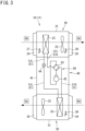
FIG. 2 is a schematic perspective view of a ventilator according to a first embodiment of the present disclosure. -
FIG. 3 is a schematic configuration diagram of the ventilator according to the first embodiment of the present disclosure. -
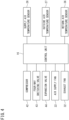
FIG. 4 is a control block diagram of the ventilator of the present disclosure. -
FIG. 5 is a schematic view showing a schematic arrangement of the ventilator according to the first embodiment of the present disclosure. -
FIG. 6 is a schematic view showing a schematic arrangement of a ventilator according to a second embodiment of the present disclosure. -
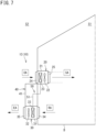
FIG. 7 is a schematic view showing a schematic arrangement of a ventilator according to a third embodiment of the present disclosure. -
FIG. 8 is a schematic view showing a schematic arrangement of a ventilator according to a fourth embodiment of the present disclosure. -
FIG. 9 is a schematic view showing a schematic arrangement of a ventilator according to a fifth embodiment of the present disclosure. -
FIG. 1 is a schematic configuration diagram of a ventilator of the present disclosure. In the following description, a ventilator 10 (seeFIG. 2 ,FIG. 3 , andFIG. 5 ) according to a first embodiment will be referred to as afirst ventilator 11, a ventilator 10 (seeFIG. 6 ) according to a second embodiment will be referred to as asecond ventilator 12, a ventilator 10 (seeFIG. 7 ) according to a third embodiment will be referred to as athird ventilator 13, a ventilator 10 (seeFIG. 8 ) according to a fourth embodiment will be referred to as afourth ventilator 14, and a ventilator 10 (seeFIG. 9 ) according to a fifth embodiment will be referred to as afifth ventilator 15. In the following description, a configuration common to the first tofifth ventilators 11 to 15 will be described when the ventilators are simply referred to as "ventilator 10". - The
ventilator 10 shown inFIG. 1 is an embodiment of the ventilator of the present disclosure, and is installed in a building such as an office building or a factory to implement ventilation of a target space. Theventilator 10 includes anair supply unit 20, anexhaust unit 30, acompressor unit 40, and arefrigerant circuit 50. - The
air supply unit 20 includes an air supply-side casing 21, anair supply fan 22, and afirst heat exchanger 23. The air supply-side casing 21 according to the present embodiment is a cubic box constituted with a panel member having a heat insulating property, and has side surfaces provided with asuction port 24 and a blow-outport 25. Theair supply fan 22 and thefirst heat exchanger 23 are disposed in the air supply-side casing 21. When theair supply fan 22 is driven, theair supply unit 20 can take air (outside air OA) in an outdoor space S2 into the air supply-side casing 21, exchange the taken air with a refrigerant in thefirst heat exchanger 23, and then release the air as a supply air SA from the blow-outport 25 toward an indoor space S1. - The
first heat exchanger 23 constitutes therefrigerant circuit 50 described later. Thefirst heat exchanger 23 is a cross-fin tube type or microchannel type heat exchanger, and is used to exchange heat between the refrigerant flowing in thefirst heat exchanger 23 and the air (outside air OA) in the outdoor space S2. - The
air supply unit 20 further includes a supplyair temperature sensor 26 and an outsideair temperature sensor 27. The supplyair temperature sensor 26 is disposed in an airflow after passing through thefirst heat exchanger 23 in the air supply-side casing 21, and can detect a temperature of the supply air SA. The outsideair temperature sensor 27 is disposed in an airflow before passing through thefirst heat exchanger 23 in the air supply-side casing 21, and can detect a temperature of the outside air OA. - The
exhaust unit 30 includes an exhaust-side casing 31, anexhaust fan 32, and asecond heat exchanger 33. The exhaust-side casing 31 according to the present embodiment is a cubic box constituted with a panel member having a heat insulating property, and has side surfaces provided with asuction port 34 and a blow-outport 35. Theexhaust fan 32 and thesecond heat exchanger 33 are disposed in the exhaust-side casing 31. When theexhaust fan 32 is driven, theexhaust unit 30 can take air in the indoor space S1 (return air RA) into the exhaust-side casing 31, cause the taken air and the refrigerant in thesecond heat exchanger 33 to exchange heat with each other, and then discharge the air as exhaust air EA from the blow-outport 35 toward the outdoor space S2. - The
second heat exchanger 33 constitutes therefrigerant circuit 50 described later. Thesecond heat exchanger 33 is a cross-fin tube type or microchannel type heat exchanger, and is used to exchange heat between the refrigerant flowing in thesecond heat exchanger 33 and the air in the indoor space S1. - The
exhaust unit 30 further includes a returnair temperature sensor 36. The returnair temperature sensor 36 is disposed in an airflow before passing through thesecond heat exchanger 33 in the exhaust-side casing 31, and can detect a temperature of the return air RA. - The
compressor unit 40 includes acasing 41, acompressor 42, a four-way switching valve 43, and anexpansion valve 44. - The
compressor 42 sucks a low-pressure gaseous refrigerant and discharges a high-pressure gaseous refrigerant. Thecompressor 42 includes a motor having the number of operating revolutions adjustable in accordance with inverter control. Thecompressor 42 is of a variable capacity type (performance variable type) having capacity (performance) variable in accordance with inverter control of the motor. Alternatively, thecompressor 42 may be of a constant capacity type. Thecompressor 42 used in theventilator 10 of the present disclosure may be configured by connecting two or more compressors in parallel. - The four-
way switching valve 43 reverses a refrigerant flow in a refrigerant pipe, and switchingly supplies one of thefirst heat exchanger 23 or thesecond heat exchanger 33 with the refrigerant discharged from thecompressor 42. Accordingly, theventilator 10 can switch between a cooling operation for cooling the outside air OA and a heating operation for heating the outside air OA. Theexpansion valve 44 is constituted by an electric valve capable of adjusting a flow rate and a pressure of a refrigerant. In theventilator 10, an opening degree of theexpansion valve 44 is controlled to adjust the pressure of the refrigerant to be supplied to thefirst heat exchanger 23. - The
refrigerant circuit 50 includes thecompressor 42, the four-way switching valve 43, theexpansion valve 44, thefirst heat exchanger 23, thesecond heat exchanger 33, and a refrigerant pipe 51 (aliquid pipe 51L and agas pipe 51G) connecting the above components. Therefrigerant circuit 50 circulates the refrigerant between thefirst heat exchanger 23 and thesecond heat exchanger 33. - In the
ventilator 10 having the above configuration, when the outside air OA is cooled and supplied by theair supply unit 20, the four-way switching valve 43 is held in a state indicated by a solid line inFIG. 1 . The high-temperature and high-pressure gaseous refrigerant discharged from thecompressor 42 flows into thesecond heat exchanger 33 of theexhaust unit 30 through the four-way switching valve 43. At this time, thesecond heat exchanger 33 functions as a condenser, and causes heat exchange with the return air RA by an activation of theexhaust fan 32 to condense and liquefy the refrigerant. The liquefied refrigerant is decompressed by theexpansion valve 44 and flows into thefirst heat exchanger 23. At this time, thefirst heat exchanger 23 functions as an evaporator, and in thefirst heat exchanger 23, the refrigerant exchanges heat with the outside air OA and evaporates. The outside air OA cooled by the evaporation of the refrigerant is supplied to the indoor space S1 as the supply air SA by theair supply fan 22. The refrigerant evaporated in thefirst heat exchanger 23 returns to thecompressor unit 40 through the refrigerant pipe 51 (gas pipe 51G), and is sucked into thecompressor 42 through the four-way switching valve 43. - In the
ventilator 10 having the above configuration, when the outside air OA is heated and supplied by theair supply unit 20, the four-way switching valve 43 is held in a state indicated by a broken line inFIG. 1 . The high-temperature and high-pressure gaseous refrigerant discharged from thecompressor 42 passes through the four-way switching valve 43 and flows into thefirst heat exchanger 23 of theair supply unit 20. At this time, thefirst heat exchanger 23 functions as a condenser, and the refrigerant exchanges heat with the outside air OA and to be condensed and liquefied in thefirst heat exchanger 23. The outside air OA heated by the condensation of the refrigerant is supplied to theindoor space S 1 by theair supply fan 22. The refrigerant liquefied in thefirst heat exchanger 23 reaches thecompressor unit 40 through the refrigerant pipe 51 (liquid pipe 51L), is decompressed to a predetermined low pressure by theexpansion valve 44, and further flows into thesecond heat exchanger 33. At this time, thesecond heat exchanger 33 functions as an evaporator, and the refrigerant exchanges heat with the return air RA and evaporates in thesecond heat exchanger 33. The refrigerant evaporated and vaporized in thesecond heat exchanger 33 is sucked into thecompressor 42 through the four-way switching valve 43. -
FIG. 3 is a control block diagram of the ventilator. Theventilator 10 includes acontrol unit 16 shown inFIG. 3 . Thecontrol unit 16 is configured to control operation of theventilator 10, and is constituted by, for example, a microcomputer including a processor such as a CPU and a memory such as a RAM or a ROM. Thecontrol unit 16 may alternatively be embodied as hardware with use of an LSI, an ASIC, an FPGA, or the like. Thecontrol unit 16 exerts a predetermined function when the processor executes a program installed in the memory. - The
control unit 16 is connected to theair supply fan 22, theexhaust fan 32, thecompressor 42, the four-way switching valve 43, and theexpansion valve 44. The supplyair temperature sensor 26, the outsideair temperature sensor 27, and the returnair temperature sensor 36 are connected to thecontrol unit 16. Thecontrol unit 16 controls operations of theair supply fan 22, theexhaust fan 32, thecompressor 42, the four-way switching valve 43, theexpansion valve 44, and the like on the basis of detection values of the temperature sensors. Furthermore, a remote controller (not shown) for a user to activate or stop theventilator 10, change settings, and the like may be connected to thecontrol unit 16. - As shown in
FIG. 2 ,FIG. 3 , andFIG. 5 , in thefirst ventilator 11, theair supply unit 20, theexhaust unit 30, and thecompressor unit 40 are integrally configured. As shown inFIG. 5 , thefirst ventilator 11 can be disposed in the outdoor space S2. In the present embodiment, the blow-outport 25 of theair supply unit 20 and thesuction port 34 of theexhaust unit 30 are disposed directly on an outer wall surface of a building B. In this case, a duct may be connected to the blow-outport 25 and thesuction port 34 to adjust a position where the supply air SA is discharged to the indoor space S1 and a position where the return air RA is sucked from the indoor space S1. - As shown in
FIG. 5 , thefirst ventilator 11 is disposed in the outdoor space S2. In this case, the air supply-side casing 21 and theair supply fan 22, and the exhaust-side casing 31 and theexhaust fan 32 are disposed in the outdoor space S2. Thefirst ventilator 11 can increase a distance between theair supply fan 22 and theexhaust fan 32 and the indoor space S1 as compared with a conventional ventilator in which the exhaust fan and the air supply fan are disposed the indoor space. Therefore, in thefirst ventilator 11, it is possible to increase a distance attenuation amount during transmission of noise generated by theair supply fan 22 and theexhaust fan 32 to the indoor space S1 as compared with the conventional ventilator. Accordingly, in thefirst ventilator 11, noise in the indoor space S1 can be suppressed. - As shown in
FIG. 6 , thesecond ventilator 12 is different from thefirst ventilator 11 in that the exhaust-side casing 31 includes afirst casing 31A and asecond casing 31B, and theexhaust unit 30 is divided into afan unit 30A accommodating theexhaust fan 32 in thefirst casing 31A and acoil unit 30B accommodating thesecond heat exchanger 33 in thesecond casing 31B. In thesecond ventilator 12, theair supply unit 20, thefan unit 30A, and thecompressor unit 40 are integrally configured, and thecoil unit 30B is a separate body. In thesecond ventilator 12, thefan unit 30A and thecoil unit 30B are connected by aduct 30C, and the return air RA sucked from the indoor space S1 is exhausted to the outdoor space S2 through thecoil unit 30B, theduct 30C, and thefan unit 30A. - As shown in
FIG. 6 , insecond ventilator 12, a portion other thancoil unit 30B is disposed in the outdoor space S2, andcoil unit 30B is disposed in the indoor space S1. In this case, theair supply unit 20 and thefan unit 30A (thefirst casing 31A and the exhaust fan 32) are disposed in the outdoor space S2. Therefore, in thesecond ventilator 12, it is possible to increase the distance attenuation amount during transmission of noise generated by theair supply fan 22 and theexhaust fan 32 to the indoor space S1 as compared with the conventional ventilator. Accordingly, in thesecond ventilator 12, noise in the indoor space S1 can be suppressed. In thesecond ventilator 12, since thecoil unit 30B is separated from thefan unit 30A, even when the outdoor space S2 and a ventilation target space are separated from each other, a heat recovery loss can be suppressed by arranging thesecond heat exchanger 33 near the ventilation target space while the noise caused by theexhaust fan 32 is suppressed. In thesecond ventilator 12 according to the present embodiment, theexhaust unit 30 is divided into thefan unit 30A and thecoil unit 30B, but theair supply unit 20 may also be divided into separate units of theair supply fan 22 and thefirst heat exchanger 23. In this case, only a unit including thefirst heat exchanger 23 is preferably disposed in the indoor space S1. - As shown in
FIG. 7 , thethird ventilator 13 is different from thefirst ventilator 11 in that theair supply unit 20 is separated from theexhaust unit 30 and thecompressor unit 40. In thethird ventilator 13, theexhaust unit 30 and thecompressor unit 40 are integrally configured, and theair supply unit 20 is a separate body. - As shown in
FIG. 7 , in thethird ventilator 13, a portion other than theair supply unit 20 is disposed in the outdoor space S2, and theair supply unit 20 is disposed in the indoor space S1. In this case, the exhaust-side casing 31 and theexhaust fan 32 are disposed in the outdoor space S2. Therefore, in thethird ventilator 13, it is possible to increase the distance attenuation amount during transmission of noise generated by theexhaust fan 32 to the indoor space S1 as compared with the conventional ventilator. Accordingly, in thethird ventilator 13, noise in the indoor space S1 can be suppressed. In thethird ventilator 13, since theair supply unit 20 is a separate body, a degree of freedom in arrangement of theair supply unit 20 is improved. In the embodiment shown inFIG. 7 , theair supply unit 20 is disposed on the outer wall of the building B. However, when a duct is connected to thesuction port 24, theair supply unit 20 can be disposed near the ventilation target space away from the outer wall. - As shown in
FIG. 8 , thefourth ventilator 14 is different from thethird ventilator 13 in that thefourth ventilator 14 includes a plurality ofair supply units 20. Although thefourth ventilator 14 according to the present embodiment includes threeair supply units 20, the number of theair supply units 20 in thefourth ventilator 14 is not limited to three, and may be two or more. - As shown in
FIG. 8 , in thefourth ventilator 14, a portion other than the plurality ofair supply units 20 is disposed in the outdoor space S2, and the plurality ofair supply unit 20 is disposed in the indoor space S1. In this case, the exhaust-side casing 31 and theexhaust fan 32 are disposed in the outdoor space S2. Therefore, in thefourth ventilator 14, it is possible to increase the distance attenuation amount during transmission of noise generated by theexhaust fan 32 to the indoor space S1 as compared with the conventional ventilator. Accordingly, in thefourth ventilator 14, noise in the indoor space S1 can be suppressed. - In the
fourth ventilator 14, the supply air SA is supplied to the indoor space S1 by the plurality ofair supply units 20, and the return air RA balanced with a total air volume of the supply air SA by the plurality ofair supply units 20 is discharged as the exhaust air EA to the outdoor space S2 by oneexhaust unit 30. In thefourth ventilator 14, the number of theexhaust units 30 is smaller than the number of theair supply units 20. This configuration facilitates installation of thefourth ventilator 14. In the present embodiment, thefourth ventilator 14 including oneexhaust unit 30 is exemplified, but the number of theexhaust units 30 in thefourth ventilator 14 is not limited to one, and may be divided into two or more. In thefourth ventilator 14, by arranging theexhaust fan 32 in the outdoor space S2, noise in the indoor space S1 can be suppressed even when a large fan that processes a return air amount corresponding to a total air supply amount of the plurality ofair supply units 20 is used as theexhaust fan 32. Similarly, by arranging thesecond heat exchanger 33 in the outdoor space S2, it is possible to use a large heat exchanger that processes an amount of heat for the return air amount corresponding to the total air supply amount of the plurality ofair supply units 20. Similarly to thesecond ventilator 12, thesecond heat exchanger 33 may be provided in the indoor space S1. When thesecond heat exchanger 33 is provided in the indoor space S1, a plurality of heat exchangers may be provided in parallel. - As shown in
FIG. 9 , thefifth ventilator 15 is different from thefourth ventilator 14 in that areturn air duct 37 connected to theexhaust unit 30 and a plurality ofsuction ports 38 provided in thereturn air duct 37 are provided. Thefifth ventilator 15 can be applied to the building B in which the indoor space S1 is partitioned into a plurality of rooms R1 to R3. - In the
fifth ventilator 15, oneair supply unit 20 and onesuction port 38 are disposed in each of the rooms R1 to R3. In the present embodiment, the number of theair supply units 20 and the number of thesuction ports 38 disposed in one room are the same. However, the air supply amount of theair supply unit 20 and the return air amount sucked from thesuction port 38 are only required to be balanced in each of the rooms R1 to R3, and the number of theair supply units 20 and the number of thesuction ports 38 are not required to be the same. - In the
fifth ventilator 15, the outside air OA taken in from anoutside air inlet 28 provided in the outer wall of the building B is distributed to eachair supply unit 20 by anair supply duct 29. In thefifth ventilator 15, thefirst heat exchanger 23 is disposed in each of the rooms R1 to R3, and each of theair supply units 20 is provided with theexpansion valve 44. Therefore, in thefifth ventilator 15, theair supply units 20 in the rooms R1 to R3 can individually adjust a supply air temperature. In the fifth ventilator, theair supply fan 22 individually supplies the supply air SA to each of the rooms R1 to R3, and theexhaust fan 32 sucks the return air RA having an amount balanced with an amount of the supply air SA from thesuction port 38. In the fifth ventilator, the return air RA sucked from thesuction port 38 of each of the rooms R1 to R3 by theexhaust fan 32 is collected by thereturn air duct 37 and discharged as the exhaust air EA to the outdoor space S2. Thesuction port 38 provided in each of the rooms R1 to R3 includes an air volume adjustment mechanism (not shown), which can individually adjust an intake amount of the suction port 38 (an air volume of the return air RA in each of the rooms R1 to R3). The air volume adjustment mechanism may be provided separately from thesuction port 38, and the air volume adjustment mechanism in this case may be a damper, a fan unit having an air volume adjustment function, or the like. - As shown in
FIG. 9 , in thefifth ventilator 15, a portion other than the plurality ofair supply units 20 is disposed in the outdoor space S2, and the plurality ofair supply unit 20 is disposed in the indoor space S1. In this case, the exhaust-side casing 31 and theexhaust fan 32 are disposed in the outdoor space S2. Therefore, in thefifth ventilator 15, it is possible to increase the distance attenuation amount during transmission of noise generated by theexhaust fan 32 to the indoor space S1 as compared with the conventional ventilator. Accordingly, in thefifth ventilator 15, noise in the indoor space S1 can be suppressed. - In the
fifth ventilator 15, thefirst heat exchanger 23 is provided in each of the rooms R1 to R3 in order to individually adjust the temperature of the supply air SA. However, since a temperature of the exhaust air EA does not need to be adjusted (in other words, the temperature of the exhaust air EA may be natural), thesecond heat exchanger 33 does not need to be provided separately in each of the rooms R1 to R3. Therefore, in thefifth ventilator 15, the return air RAin each of the rooms R1 to R3 is collected and processed by oneexhaust unit 30. In thefifth ventilator 15, by reducing the number of theexhaust units 30, an installation space of theexhaust units 30 in the outdoor space S2 can be easily secured, and man-hours required for installation can also be reduced. In thefifth ventilator 15, by arranging theexhaust fan 32 in the outdoor space S2, noise in each of the rooms R1 to R3 can be suppressed even when a large fan that processes a return air amount corresponding to a total air supply amount of the plurality ofair supply units 20 is used as theexhaust fan 32. Similarly, by arranging thesecond heat exchanger 33 in the outdoor space S2, it is possible to use a large heat exchanger that processes an amount of heat for the return air amount corresponding to the total air supply amount of the plurality ofair supply units 20. Similarly to thesecond ventilator 12, thesecond heat exchanger 33 may be provided in the indoor space S1. When thesecond heat exchanger 33 is provided in the indoor space S1, a plurality of heat exchangers may be provided integrally with or separately from thesuction ports 38 of the rooms R1 to R3. -
- (1) The
ventilator 10 of the present disclosure includes therefrigerant circuit 50 through which the refrigerant flows, therefrigerant circuit 50 including thecompressor 42, thefirst heat exchanger 23, and thesecond heat exchanger 33 that are connected by therefrigerant pipe 51, theair supply fan 22 that supplies air in an outdoor space S2 to the indoor space S1 through thefirst heat exchanger 23, theexhaust fan 32 that exhausts air in the indoor space S1 to the outdoor space S2 through thesecond heat exchanger 33, and the exhaust-side casing 31 that accommodates theexhaust fan 32, in which theexhaust fan 32 and the exhaust-side casing 31 are disposed in the outdoor space S2.
In theventilator 10 having such a configuration, noise in the indoor space S1 can be suppressed by installing theexhaust fan 32 in the outdoor space S2. In theventilator 10 having such a configuration, since theexhaust fan 32 disposed in the outdoor space S2 is accommodated in the exhaust-side casing 31, the noise of theexhaust fan 32 is less likely to be transmitted to the indoor space S1. - (2) In the
ventilator 10 of the present disclosure, thesecond heat exchanger 33 is accommodated in the exhaust-side casing 31.
In theventilator 10 having such a configuration, since theexhaust fan 32 and thesecond heat exchanger 33 are accommodated in the exhaust-side casing 31 to be unitized, construction of ducts and refrigerant pipes around theexhaust fan 32 and thesecond heat exchanger 33 in a construction site is facilitated. - (3) The
fifth ventilator 15 of the present disclosure further includes the air supply-side casing 21, and the plurality ofair supply units 20 that accommodates thefirst heat exchanger 23 and theair supply fan 22 in the air supply-side casing 21, in which the plurality ofair supply units 20 individually supplies the air in the outdoor space S2 to the indoor space S1.
In thefifth ventilator 15 having such a configuration, when the indoor space S1 is divided into the plurality of rooms R1 to R3, theair supply unit 20 can individually supply the supply air SA to each of the rooms R1 to R3. - (4) In the
fifth ventilator 15 of the present disclosure, theexhaust fan 32 exhausts the air in the indoor space S1 to the outdoor space S2 through the plurality ofsuction ports 38 that is disposed in the indoor space S1 and sucks the air in the indoor space S1. - In the
fifth ventilator 15 having such a configuration, the number of theexhaust fans 32 can be reduced. - The present disclosure should not be limited to the above exemplification, but is intended to include any modification recited in the claims within meanings and a scope equivalent to those of the claims.
-
- 10
- ventilator
- 11
- first ventilator
- 12
- second ventilator
- 13
- third ventilator
- 14
- fourth ventilator
- 15
- fifth ventilator
- 20
- air supply unit
- 21
- air supply-side casing
- 22
- air supply fan
- 23
- first heat exchanger
- 30
- exhaust unit
- 31
- exhaust-side casing
- 32
- exhaust fan
- 33
- second heat exchanger
- 38
- suction port
- 42
- compressor
- 50
- refrigerant circuit
- 51
- refrigerant pipe
- S1
- indoor space
- S2
- outdoor space
Claims (4)
- A ventilator (10) comprising:a refrigerant circuit (50) through which a refrigerant flows, the refrigerant circuit (50) including a compressor (42), a first heat exchanger (23), and a second heat exchanger (33) that are connected by a refrigerant pipe (51);an air supply fan (22) that supplies air in an outdoor space (S2) to an indoor space (S1) through the first heat exchanger (23);an exhaust fan (32) that exhausts air in the indoor space (S1) to the outdoor space (S2) through the second heat exchanger (33); andan exhaust-side casing (31) that accommodates the exhaust fan (32);wherein the exhaust fan (32) and the exhaust-side casing (31) are disposed in the outdoor space.
- The ventilator (10) according to claim 1, wherein the second heat exchanger (33) is accommodated in the exhaust-side casing (31).
- The ventilator (10) of claim 1 or 2, further comprising:an air supply-side casing (21); anda plurality of air supply units (20) that accommodates the first heat exchanger (23) and the air supply fan (22) in the air supply-side casing (21),wherein the plurality of air supply units (20) individually supplies the air in the outdoor space (S2) to the indoor space (S1).
- The ventilator (10) according to any one of claims 1 to 3, wherein the exhaust fan (32) exhausts the air in the indoor space (S1) to the outdoor space (S2) through a plurality of suction ports (38) that is disposed in the indoor space (S1) and sucks the air in the indoor space (S1).
Applications Claiming Priority (2)
| Application Number | Priority Date | Filing Date | Title |
|---|---|---|---|
| JP2021160922A JP7332928B2 (en) | 2021-09-30 | 2021-09-30 | ventilator |
| PCT/JP2022/029587 WO2023053711A1 (en) | 2021-09-30 | 2022-08-02 | Ventilation device |
Publications (2)
| Publication Number | Publication Date |
|---|---|
| EP4411268A1 true EP4411268A1 (en) | 2024-08-07 |
| EP4411268A4 EP4411268A4 (en) | 2025-01-15 |
Family
ID=85782269
Family Applications (1)
| Application Number | Title | Priority Date | Filing Date |
|---|---|---|---|
| EP22875588.0A Pending EP4411268A4 (en) | 2021-09-30 | 2022-08-02 | VENTILATION DEVICE |
Country Status (6)
| Country | Link |
|---|---|
| US (1) | US12584640B2 (en) |
| EP (1) | EP4411268A4 (en) |
| JP (1) | JP7332928B2 (en) |
| CN (1) | CN118119798A (en) |
| AU (1) | AU2022354365B2 (en) |
| WO (1) | WO2023053711A1 (en) |
Family Cites Families (44)
| Publication number | Priority date | Publication date | Assignee | Title |
|---|---|---|---|---|
| US2817217A (en) | 1954-07-01 | 1957-12-24 | Stewart Warner Corp | Air conditioning means |
| GB828979A (en) | 1957-06-15 | 1960-02-24 | Pellizzetti Italo | Air conditioner |
| JPS5163261U (en) | 1974-11-13 | 1976-05-18 | ||
| JPS52115548A (en) * | 1976-03-24 | 1977-09-28 | Matsushita Electric Ind Co Ltd | Heat pump type air conditioning system |
| JPS6136641A (en) * | 1984-07-26 | 1986-02-21 | Matsushita Electric Ind Co Ltd | Air conditioning and air ventilation device |
| JPS62237231A (en) | 1986-04-04 | 1987-10-17 | Kankyo Eng:Kk | Air conditioner |
| JPH0733057Y2 (en) * | 1987-11-12 | 1995-07-31 | 直樹 佐竹 | air conditioner |
| US5372182A (en) | 1993-05-24 | 1994-12-13 | Gore; Thomas L. | Modular regenerator pre-conditioner air system |
| US6038879A (en) | 1995-08-08 | 2000-03-21 | Yvon Turcotte | Combined air exchange and air conditioning unit |
| JPH09229500A (en) | 1995-12-27 | 1997-09-05 | Mando Mach Co Ltd | Multi room air conditioner |
| US6347527B1 (en) * | 1997-12-02 | 2002-02-19 | Louis J. Bailey | Integrated system for heating, cooling and heat recovery ventilation |
| JP2001116321A (en) * | 1999-10-18 | 2001-04-27 | Takashi Mita | Heat exchange air conditioning system |
| JP2002276999A (en) | 2001-03-16 | 2002-09-25 | Matsushita Electric Ind Co Ltd | Air ventilation purification device |
| CN1139762C (en) * | 2001-12-12 | 2004-02-25 | 邓金荣 | Energy-saving air conditioner supply fresh air |
| JP2005265401A (en) * | 2004-02-18 | 2005-09-29 | Sanyo Electric Co Ltd | Air conditioner |
| DE202004018206U1 (en) | 2004-11-18 | 2005-01-27 | Von Staudach, Karl | Climate control assembly has a ventilator with heating and ventilation components e.g. a heat exchanger, compressor |
| JP4646611B2 (en) * | 2004-12-07 | 2011-03-09 | 三洋電機株式会社 | Air conditioner |
| CA2600526A1 (en) * | 2005-03-10 | 2006-09-21 | Aircuity, Inc. | Dynamic control of dilution ventilation in one-pass, critical environments |
| JP5050687B2 (en) | 2007-06-27 | 2012-10-17 | マックス株式会社 | Ventilation air conditioner |
| JP2010127522A (en) * | 2008-11-27 | 2010-06-10 | Daikin Ind Ltd | Air conditioning system |
| KR101004640B1 (en) * | 2010-05-14 | 2011-01-03 | 주식회사 신성냉동공조 | Electric heat exchanger for indoor ventilation |
| JP5786646B2 (en) | 2011-10-27 | 2015-09-30 | ダイキン工業株式会社 | Humidity control device |
| US20150253018A1 (en) * | 2012-09-04 | 2015-09-10 | Daikin Industries, Ltd. | Humidity control device |
| CN104822998B (en) * | 2012-12-10 | 2017-07-28 | 三菱电机株式会社 | Air Conditioning System |
| US10180257B2 (en) | 2013-07-26 | 2019-01-15 | Whirlpool Corporation | Air conditioning systems for at least two rooms using a single outdoor unit |
| JP6250148B2 (en) * | 2014-05-13 | 2017-12-20 | 三菱電機株式会社 | Air conditioning system |
| CN204153894U (en) | 2014-08-14 | 2015-02-11 | 张馨月 | A kind of Novel separated heat-pump-type heat recovery fresh air unit |
| JP6708369B2 (en) * | 2015-04-30 | 2020-06-10 | ダイキン工業株式会社 | Air conditioning ventilation system |
| ES2638859T3 (en) | 2015-04-17 | 2017-10-24 | Daikin Europe N.V. | Assembly and procedure for mounting a heat source unit of an air conditioner at the site of the air conditioner |
| CN205227615U (en) * | 2015-12-18 | 2016-05-11 | 上海朗绿建筑科技有限公司 | Take new trend dehumidification unit of heat of condensation recovery |
| CN106524317B (en) * | 2016-12-30 | 2022-04-01 | 山东华科规划建筑设计有限公司 | Quality-divided heat recovery refrigerant supercooling reheating air conditioner and air treatment method thereof |
| JP6414354B1 (en) * | 2017-03-31 | 2018-10-31 | ダイキン工業株式会社 | Air conditioning system |
| CN108253540B (en) * | 2018-03-07 | 2024-01-16 | 东莞科尼恩环境有限公司 | Multifunctional air conditioner |
| WO2019194063A1 (en) | 2018-04-02 | 2019-10-10 | 三菱電機株式会社 | Air conditioner ventilation device and air conditioner ventilation method |
| CN208253831U (en) * | 2018-04-19 | 2018-12-18 | 西安工程大学 | In conjunction with the recovery type heat split-type air conditioner of mechanical refrigeration and evaporation cooling technique |
| WO2020053929A1 (en) | 2018-09-10 | 2020-03-19 | 三菱電機株式会社 | Air conditioning device |
| US11187418B1 (en) | 2019-01-04 | 2021-11-30 | Katerra Inc. | HVAC system with modular architecture |
| KR102202972B1 (en) * | 2019-03-20 | 2021-01-13 | 엘지전자 주식회사 | Ventilation System |
| JP7457229B2 (en) | 2019-05-10 | 2024-03-28 | ダイキン工業株式会社 | air conditioning system |
| NL2023182B1 (en) | 2019-05-23 | 2020-12-01 | Heering Group B V | Air conditioning module, modular air conditioning system, transport vehicle and method |
| JP7394560B2 (en) | 2019-08-30 | 2023-12-08 | 三菱電機株式会社 | Air conditioning control device, air conditioning control method, and air conditioning control program |
| JP7519176B2 (en) * | 2019-09-12 | 2024-07-19 | ダイキン工業株式会社 | Air Conditioning System |
| CN111189120B (en) | 2019-12-31 | 2021-09-21 | 阿尔西制冷工程技术(北京)有限公司 | Air conditioning system |
| US11655996B2 (en) | 2021-06-02 | 2023-05-23 | Lubnevskiy Konstantin Kazimirovich | Air to air heat pump with heat recovery function and exhaust air humidity for heating ventilation and air conditioning systems |
-
2021
- 2021-09-30 JP JP2021160922A patent/JP7332928B2/en active Active
-
2022
- 2022-08-02 CN CN202280066260.1A patent/CN118119798A/en active Pending
- 2022-08-02 AU AU2022354365A patent/AU2022354365B2/en active Active
- 2022-08-02 EP EP22875588.0A patent/EP4411268A4/en active Pending
- 2022-08-02 WO PCT/JP2022/029587 patent/WO2023053711A1/en not_active Ceased
-
2024
- 2024-03-12 US US18/602,740 patent/US12584640B2/en active Active
Also Published As
| Publication number | Publication date |
|---|---|
| JP2023050690A (en) | 2023-04-11 |
| AU2022354365B2 (en) | 2024-06-27 |
| US20240210049A1 (en) | 2024-06-27 |
| EP4411268A4 (en) | 2025-01-15 |
| US12584640B2 (en) | 2026-03-24 |
| WO2023053711A1 (en) | 2023-04-06 |
| CN118119798A (en) | 2024-05-31 |
| AU2022354365A1 (en) | 2024-03-21 |
| JP7332928B2 (en) | 2023-08-24 |
Similar Documents
| Publication | Publication Date | Title |
|---|---|---|
| US11073301B2 (en) | Heat pump with integrated energy recovery ventilator (ERV) | |
| US10907641B2 (en) | Multi-fan assembly control | |
| US11162704B2 (en) | Indoor and outdoor units for an HVAC system | |
| US10605469B2 (en) | System and method for capture of waste heat in an HVAC unit | |
| EP3792565B1 (en) | Air conditioning system | |
| WO2023276535A1 (en) | Air conditioning system | |
| JP7260827B2 (en) | Ventilation and air conditioning system | |
| US20240219065A1 (en) | Ventilator and air conditioning system | |
| US10670316B2 (en) | Compressor and fan staging in heating, ventilation, and air conditioning systems | |
| KR20080073602A (en) | Multi air conditioner and its operation method | |
| US12584640B2 (en) | Ventilator | |
| JP2023007074A (en) | air conditioning system | |
| US11067319B2 (en) | Heat exchanger with multiple conduits and valve control system | |
| US12595925B2 (en) | Air conditioning system | |
| US20190376697A1 (en) | Over-bent coil arrangements for climate management systems | |
| JP7590654B2 (en) | Ventilation system | |
| US20240328648A1 (en) | Ventilation system | |
| JP6745895B2 (en) | Air conditioning system | |
| US20180094842A1 (en) | Combined suction header and accumulator unit | |
| KR20190000584A (en) | Air conditioner | |
| CN118043602A (en) | Ventilation and air conditioning systems |
Legal Events
| Date | Code | Title | Description |
|---|---|---|---|
| STAA | Information on the status of an ep patent application or granted ep patent |
Free format text: STATUS: THE INTERNATIONAL PUBLICATION HAS BEEN MADE |
|
| PUAI | Public reference made under article 153(3) epc to a published international application that has entered the european phase |
Free format text: ORIGINAL CODE: 0009012 |
|
| STAA | Information on the status of an ep patent application or granted ep patent |
Free format text: STATUS: REQUEST FOR EXAMINATION WAS MADE |
|
| 17P | Request for examination filed |
Effective date: 20240311 |
|
| AK | Designated contracting states |
Kind code of ref document: A1 Designated state(s): AL AT BE BG CH CY CZ DE DK EE ES FI FR GB GR HR HU IE IS IT LI LT LU LV MC MK MT NL NO PL PT RO RS SE SI SK SM TR |
|
| DAV | Request for validation of the european patent (deleted) | ||
| DAX | Request for extension of the european patent (deleted) | ||
| A4 | Supplementary search report drawn up and despatched |
Effective date: 20241212 |
|
| RIC1 | Information provided on ipc code assigned before grant |
Ipc: F24F 7/08 20060101ALI20241206BHEP Ipc: F24F 1/0038 20190101ALI20241206BHEP Ipc: F24F 13/30 20060101ALI20241206BHEP Ipc: F24F 13/20 20060101AFI20241206BHEP |
|
| P01 | Opt-out of the competence of the unified patent court (upc) registered |
Free format text: CASE NUMBER: APP_1028/2025 Effective date: 20250108 |
|
| STAA | Information on the status of an ep patent application or granted ep patent |
Free format text: STATUS: EXAMINATION IS IN PROGRESS |
|
| 17Q | First examination report despatched |
Effective date: 20250813 |