EP4411215A1 - Light source device and projector - Google Patents
Light source device and projector Download PDFInfo
- Publication number
- EP4411215A1 EP4411215A1 EP24155926.9A EP24155926A EP4411215A1 EP 4411215 A1 EP4411215 A1 EP 4411215A1 EP 24155926 A EP24155926 A EP 24155926A EP 4411215 A1 EP4411215 A1 EP 4411215A1
- Authority
- EP
- European Patent Office
- Prior art keywords
- light
- face
- reflecting
- source device
- pressing
- Prior art date
- Legal status (The legal status is an assumption and is not a legal conclusion. Google has not performed a legal analysis and makes no representation as to the accuracy of the status listed.)
- Granted
Links
Images


Classifications
-
- G—PHYSICS
- G03—PHOTOGRAPHY; CINEMATOGRAPHY; ANALOGOUS TECHNIQUES USING WAVES OTHER THAN OPTICAL WAVES; ELECTROGRAPHY; HOLOGRAPHY
- G03B—APPARATUS OR ARRANGEMENTS FOR TAKING PHOTOGRAPHS OR FOR PROJECTING OR VIEWING THEM; APPARATUS OR ARRANGEMENTS EMPLOYING ANALOGOUS TECHNIQUES USING WAVES OTHER THAN OPTICAL WAVES; ACCESSORIES THEREFOR
- G03B21/00—Projectors or projection-type viewers; Accessories therefor
- G03B21/14—Details
- G03B21/20—Lamp housings
- G03B21/2006—Lamp housings characterised by the light source
- G03B21/2033—LED or laser light sources
- G03B21/204—LED or laser light sources using secondary light emission, e.g. luminescence or fluorescence
-
- G—PHYSICS
- G02—OPTICS
- G02B—OPTICAL ELEMENTS, SYSTEMS OR APPARATUS
- G02B6/00—Light guides; Structural details of arrangements comprising light guides and other optical elements, e.g. couplings
- G02B6/0001—Light guides; Structural details of arrangements comprising light guides and other optical elements, e.g. couplings specially adapted for lighting devices or systems
- G02B6/0003—Light guides; Structural details of arrangements comprising light guides and other optical elements, e.g. couplings specially adapted for lighting devices or systems the light guides being doped with fluorescent agents
-
- G—PHYSICS
- G02—OPTICS
- G02B—OPTICAL ELEMENTS, SYSTEMS OR APPARATUS
- G02B6/00—Light guides; Structural details of arrangements comprising light guides and other optical elements, e.g. couplings
- G02B6/0001—Light guides; Structural details of arrangements comprising light guides and other optical elements, e.g. couplings specially adapted for lighting devices or systems
- G02B6/0011—Light guides; Structural details of arrangements comprising light guides and other optical elements, e.g. couplings specially adapted for lighting devices or systems the light guides being planar or of plate-like form
- G02B6/0033—Means for improving the coupling-out of light from the light guide
- G02B6/005—Means for improving the coupling-out of light from the light guide provided by one optical element, or plurality thereof, placed on the light output side of the light guide
- G02B6/0055—Reflecting element, sheet or layer
-
- G—PHYSICS
- G03—PHOTOGRAPHY; CINEMATOGRAPHY; ANALOGOUS TECHNIQUES USING WAVES OTHER THAN OPTICAL WAVES; ELECTROGRAPHY; HOLOGRAPHY
- G03B—APPARATUS OR ARRANGEMENTS FOR TAKING PHOTOGRAPHS OR FOR PROJECTING OR VIEWING THEM; APPARATUS OR ARRANGEMENTS EMPLOYING ANALOGOUS TECHNIQUES USING WAVES OTHER THAN OPTICAL WAVES; ACCESSORIES THEREFOR
- G03B21/00—Projectors or projection-type viewers; Accessories therefor
- G03B21/14—Details
- G03B21/20—Lamp housings
- G03B21/2006—Lamp housings characterised by the light source
- G03B21/2013—Plural light sources
-
- G—PHYSICS
- G03—PHOTOGRAPHY; CINEMATOGRAPHY; ANALOGOUS TECHNIQUES USING WAVES OTHER THAN OPTICAL WAVES; ELECTROGRAPHY; HOLOGRAPHY
- G03B—APPARATUS OR ARRANGEMENTS FOR TAKING PHOTOGRAPHS OR FOR PROJECTING OR VIEWING THEM; APPARATUS OR ARRANGEMENTS EMPLOYING ANALOGOUS TECHNIQUES USING WAVES OTHER THAN OPTICAL WAVES; ACCESSORIES THEREFOR
- G03B21/00—Projectors or projection-type viewers; Accessories therefor
- G03B21/14—Details
- G03B21/20—Lamp housings
- G03B21/2006—Lamp housings characterised by the light source
- G03B21/2033—LED or laser light sources
-
- G—PHYSICS
- G03—PHOTOGRAPHY; CINEMATOGRAPHY; ANALOGOUS TECHNIQUES USING WAVES OTHER THAN OPTICAL WAVES; ELECTROGRAPHY; HOLOGRAPHY
- G03B—APPARATUS OR ARRANGEMENTS FOR TAKING PHOTOGRAPHS OR FOR PROJECTING OR VIEWING THEM; APPARATUS OR ARRANGEMENTS EMPLOYING ANALOGOUS TECHNIQUES USING WAVES OTHER THAN OPTICAL WAVES; ACCESSORIES THEREFOR
- G03B21/00—Projectors or projection-type viewers; Accessories therefor
- G03B21/14—Details
- G03B21/20—Lamp housings
- G03B21/2066—Reflectors in illumination beam
-
- G—PHYSICS
- G03—PHOTOGRAPHY; CINEMATOGRAPHY; ANALOGOUS TECHNIQUES USING WAVES OTHER THAN OPTICAL WAVES; ELECTROGRAPHY; HOLOGRAPHY
- G03B—APPARATUS OR ARRANGEMENTS FOR TAKING PHOTOGRAPHS OR FOR PROJECTING OR VIEWING THEM; APPARATUS OR ARRANGEMENTS EMPLOYING ANALOGOUS TECHNIQUES USING WAVES OTHER THAN OPTICAL WAVES; ACCESSORIES THEREFOR
- G03B21/00—Projectors or projection-type viewers; Accessories therefor
- G03B21/14—Details
- G03B21/20—Lamp housings
- G03B21/208—Homogenising, shaping of the illumination light
Definitions
- the present disclosure relates to a light source device and a projector.
- a light source device used for a projector, there is proposed a light source device using fluorescence emitted from a phosphor when irradiating the phosphor with excitation light emitted from a light emitting element.
- a light source device provided with a light source for emitting blue excitation light, a phosphor rod for converting the excitation light into fluorescence, and a mirror for returning the fluorescence emitted from a surface at an opposite side to an exit surface of the phosphor rod.
- the mirror is disposed at a position distant from the phosphor rod.
- a proportion of the fluorescence reflected toward a direction deviated from the phosphor rod to the fluorescence emitted from the phosphor rod is high. Therefore, it is difficult to sufficiently return the fluorescence to the phosphor rod, and there is a problem that the loss of the fluorescence increases.
- the description is hereinabove presented citing the light source device accompanied by a wavelength conversion as an example, there is substantially the same problem also in a light source device not accompanied by the wavelength conversion. It is desired to provide the light source device which is low in loss of the output light, and which is capable of emitting the light having a desired intensity.
- the light source device includes a light emitting element configured to emit light, a light guide member configured to guide the light emitted from the light emitting element, a reflecting member having a reflecting surface configured to reflect the light proceeding through the light guide member, and a pressing member configured to press the reflecting member against the light guide member.
- the light guide member includes a first face and a second face located at respective sides opposite to each other in a first direction as a longitudinal direction of the light guide member, and a third face and a fourth face located at respective sides opposite to each other in a second direction in an imaginary plane perpendicular to the first direction.
- the light guided through the light guide member is emitted from the first face.
- the light emitting element is disposed so as to be opposed to the third face.
- the second face and the reflecting surface have contact with each other, and the pressing member is configured to press the reflecting member from a surface at an opposite side to the reflecting surface of the reflecting member toward the second face.
- a projector includes the light source device according to one of the aspects of the present disclosure, a light modulation device configured to modulate the light emitted from the light source device in accordance with image information, and a projection optical device configured to project the light modulated by the light modulation device.
- a projector according to the present embodiment is an example of a projector using liquid crystal panels as light modulation devices.
- constituents are shown with respective dimensional scale ratios different from each other in some cases in order to make the constituents eye-friendly.
- FIG. 1 is a diagram showing a schematic configuration of a projector 1 according to the present embodiment.
- the projector 1 is a projection-type image display device for displaying a color image on a screen (a projection target surface) SCR.
- the projector 1 is provided with three light modulation devices corresponding to respective colored light, namely red light LR, green light LG, and blue light LB.
- the projector 1 is provided with a first illumination device 20, a second illumination device 21, a color separation optical system 3, a light modulation device 4R, a light modulation device 4G, a light modulation device 4B, a light combining element 5, and a projection optical device 6.
- the first illumination device 20 emits fluorescence Y having a yellow color toward the color separation optical system 3.
- the second illumination device 21 emits the blue light LB toward the light modulation device 4B. The detailed configurations of the first illumination device 20 and the second illumination device 21 will be described later.
- a Z axis is an axis along a vertical direction of the projector 1.
- An X axis is an axis parallel to an optical axis AX1 of the first illumination device 20 and an optical axis AX2 of the second illumination device 21, and is an axis along a front-back direction of the projector 1.
- the Y axis is an axis perpendicular to the X axis and the Z axis, and is an axis along a horizontal direction of the projector 1.
- the optical axis AX1 of the first illumination device 20 is a central axis of the fluorescence Y emitted from the first illumination device 20.
- the optical axis AX2 of the second illumination device 21 is a central axis of the blue light LB emitted from the second illumination device 21.
- the color separation optical system 3 separates the fluorescence Y having the yellow color emitted from the first illumination device 20 into the red light LR and the green light LG.
- the color separation optical system 3 is provided with a dichroic mirror 7, a first reflecting mirror 8a, and a second reflecting mirror 8b.
- the dichroic mirror 7 separates the fluorescence Y into the red light LR and the green light LG.
- the dichroic mirror 7 transmits the red light LR, and at the same time, reflects the green light LG.
- the second reflecting mirror 8b is arranged in a light path of the green light LG.
- the second reflecting mirror 8b reflects the green light LG, which has been reflected by the dichroic mirror 7, toward the light modulation device 4G.
- the first reflecting mirror 8a is arranged in a light path of the red light LR.
- the first reflecting mirror 8a reflects the red light LR, which has been transmitted through the dichroic mirror 7, toward the light modulation device 4R.
- the blue light LB emitted from the second illumination device 21 is reflected by a reflecting mirror 9 toward the light modulation device 4B.
- the configuration of the second illumination device 21 will hereinafter be described.
- the second illumination device 21 is provided with a light source unit 81, a condenser lens 82, a diffuser plate 83, a rod lens 86, and a relay lens 87.
- the light source unit 81 is formed of at least one semiconductor laser.
- the light source unit 81 emits the blue light LB consisting of a laser beam. It should be noted that the light source unit 81 can also be formed of an LED for emitting blue light besides the semiconductor laser.
- the condenser lens 82 is formed of a convex lens.
- the condenser lens 82 makes the blue light LB emitted from the light source unit 81 enter the diffuser plate 83 in a state of being substantially converged.
- the diffuser plate 83 diffuses the blue light LB emitted from the condenser lens 82 at a predetermined diffusion angle to generate the blue light LB having a substantially homogenous light distribution similarly to the fluorescence Y emitted from the first illumination device 20.
- the diffuser plate 83 there is used, for example, frosted glass made of optical glass.
- the rod lens 86 has a prismatic shape extending along a direction of the optical axis AX2 of the second illumination device 21.
- the rod lens 86 has a light incidence end plane 86a, and a light exit end surface 86b located at an opposite side to the light incidence end plane 86a.
- the diffuser plate 83 is fixed to the light incidence end plane 86a of the rod lens 86 via an optical adhesive (not shown). It is desirable to make the refractive index of the diffuser plate 83 and the refractive index of the rod lens 86 coincide with each other as precise as possible.
- the blue light LB is emitted from the light exit end surface 86b in the state in which homogeneity of an illuminance distribution is enhanced by propagating through the rod lens 86 while being totally reflected.
- the blue light LB emitted from the rod lens 86 enters the relay lens 87.
- the relay lens 87 makes the blue light LB having been enhanced in homogeneity of the illuminance distribution by the rod lens 86 enter the reflecting mirror 9.
- the shape of the light exit end surface 86b of the rod lens 86 is a rectangular shape substantially similar to a shape of an image formation area of the light modulation device 4B.
- the blue light LB emitted from the rod lens 86 efficiently enters the image formation area of the light modulation device 4B.
- the light modulation device 4R modulates the red light LR in accordance with image information to form image light corresponding to the red light LR.
- the light modulation device 4G modulates the green light LG in accordance with the image information to form image light corresponding to the green light LG.
- the light modulation device 4B modulates the blue light LB in accordance with the image information to form image light corresponding to the blue light LB.
- each of the light modulation devices 4R, 4G, and 4B there is used, for example, a transmissive liquid crystal panel. Further, at the incident side and the exit side of each of the liquid crystal panels, there are respectively arranged polarization plates (not shown). The polarization plates each transmit linearly-polarized light of a specific polarization direction.
- a field lens 10R At the incident side of the light modulation device 4R, there is arranged a field lens 10R. At the incident side of the light modulation device 4G, there is arranged a field lens 10G. At the incident side of the light modulation device 4B, there is arranged a field lens 10B.
- the field lens 10R collimates a principal ray of the red light LR entering the light modulation device 4R.
- the field lens 10G collimates a principal ray of the green light LG entering the light modulation device 4G.
- the field lens 10B collimates a principal ray of the blue light LB entering the light modulation device 4B.
- the light combining element 5 combines the image light corresponding to the red light LR, the image light corresponding to the green light LG, and the image light corresponding to the blue light LB with each other in response to incidence of the image light emitted from the light modulation device 4R, the image light emitted from the light modulation device 4G, and the image light emitted from the light modulation device 4B, and then emits the image light thus combined toward the projection optical device 6.
- the light combining element 5 there is used, for example, a cross dichroic prism.
- the projection optical device 6 is constituted by a plurality of projection lenses.
- the projection optical device 6 projects the image light having been combined by the light combining element 5 toward the screen SCR in an enlarged manner. Thus, an image is displayed on the screen SCR.
- a configuration of the first illumination device 20 will hereinafter be described.
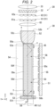
- FIG. 2 is a schematic diagram showing a general configuration of the first illumination device 20.
- the first illumination device 20 is provided with a light source device 30, a collimating optical system 63, an integrator optical system 31, a polarization conversion element 32, and a superimposing optical system 33.
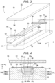
- FIG. 3 is a perspective view of the light source device 30, and shows a state in which some of the members are exploded.
- the light source device 30 is provided with a wavelength conversion member 50, a light source unit 51, a support member 54, a fixation member 65, a reflecting mirror 53, a pressing member 58, and an angle conversion member 52.
- the light source unit 51 is provided with a substrate 55 and light emitting elements 56.
- the reflecting mirror 53 in the present embodiment corresponds to a reflecting member in the appended claims.
- the wavelength conversion member 50 in the present embodiment corresponds to a light guide member in the appended claims.
- the wavelength conversion member 50 has a quadrangular prismatic shape extending in the X-axis direction, and has six faces.
- a side extending in the X-axis direction of the wavelength conversion member 50 is longer than a side extending in the Y-axis direction and a side extending in the Z-axis direction.
- the X-axis direction corresponds to a longitudinal direction of the wavelength conversion member 50.
- the length of the side extending in the Y-axis direction and the length of the side extending in the Z-axis direction are equal to each other.
- a cross-sectional shape of the wavelength conversion member 50 cut by a plane perpendicular to the X-axis direction is a square. It should be noted that the cross-sectional shape of the wavelength conversion member 50 cut by the plane perpendicular to the X-axis direction can be a rectangle.
- the wavelength conversion member 50 has a first face 50a and a second face 50b, a third face 50c and a fourth face50d, and a fifth face 50e and a sixth face 50f.
- the first face 50a and the second face 50b cross the longitudinal direction (the X-axis direction) of the wavelength conversion member 50, and are located at respective sides opposite to each other.
- the third face 50c and the fourth face 50d cross the first face 50a and the second face 50b, and are located at respective sides opposite to each other in the Y-axis direction in an imaginary plane perpendicular to the longitudinal direction.
- the fifth face 50e and the sixth face 50f cross the third face 50c and the fourth face 50d, and are located at respective sides opposite to each other in the Z-axis direction in the imaginary plane perpendicular to the longitudinal direction.
- the third face 50c, the fourth face 50d, the fifth face 50e, and the sixth face 50f are collectively referred to as side surfaces in some cases.
- the X-axis direction in the present embodiment corresponds to a first direction in the appended claims.
- the Y-axis direction in the present embodiment corresponds to a second direction in the appended claims.
- the Z-axis direction in the present embodiment corresponds to a third direction in the appended claims.
- the wavelength conversion member 50 includes a phosphor, and converts excitation light E having a first wavelength band into the fluorescence Y having a second wavelength band different from the first wavelength band.
- the excitation light E enters the wavelength conversion member 50 from the third face 50c.
- the fluorescence Y is guided inside the wavelength conversion member 50, and is then emitted from the first face 50a.
- the excitation light E in the present embodiment corresponds to first light in the appended claims.
- the fluorescence Y in the present embodiment corresponds to second light in the appended claims.
- the wavelength conversion member 50 includes a ceramic phosphor made of a polycrystalline phosphor for wavelength-converting the excitation light E into the fluorescence Y.
- the second wavelength band which the fluorescence Y has is a yellow wavelength band of, for example, 490 through 750 nm.
- the fluorescence Y is yellow fluorescence including a red light component and a green light component.
- the wavelength conversion member 50 can include a single-crystal phosphor instead of the polycrystalline phosphor.
- the wavelength conversion member 50 can also be formed of fluorescent glass.
- the wavelength conversion member 50 can also be formed of a material obtained by dispersing a number of phosphor particles in a binder made of glass or resin. The wavelength conversion member 50 made of such a material converts the excitation light E in the first wavelength band into the fluorescence Y in the second wavelength band.
- the material of the wavelength conversion member 50 includes, for example, an yttrium aluminum garnet (YAG) phosphor.
- YAG:Ce including cerium (Ce) as an activator agent as an example, as the material of the wavelength conversion member 50, there is used a material obtained by mixing raw powder including constituent elements such as Y 2 O 3 , Al 2 O 3 , and CeO 3 to cause the solid-phase reaction, Y-Al-O amorphous particles obtained by a wet process such as a coprecipitation process or a sol-gel process, and YAG particles obtained by a gas-phase process such as a spray drying process, a flame heat decomposition process, or a thermal plasma process.
- the light source unit 51 is provided with the light emitting elements 56 for emitting the excitation light E in the first wavelength band.
- the light emitting elements 56 are each formed of, for example, a light emitting diode (LED).
- the light emitting elements 56 are disposed so as to be opposed to the third face 50c of the wavelength conversion member 50.
- the light emitting elements 56 emit the excitation light E toward the third face 50c.
- the first wavelength band is a wavelength band from a blue color to a violet color of, for example, 400 nm through 480 nm, and has a peak wavelength of, for example, 445 nm.
- the light source unit 51 is disposed so as to be opposed to one of the four side surfaces along the longitudinal direction of the wavelength conversion member 50.
- the substrate 55 supports the light emitting elements 56.
- the light source unit 51 is constituted by the light emitting elements 56 and the substrate 55 in the case of the present embodiment, but can also be provided with other optical members such as a light guide plate, a diffuser plate, or a lens besides the above.
- the plurality of light emitting elements 56 are used in the present embodiment, the number of the light emitting elements 56 is not particularly limited.
- the support member 54 is disposed so as to surround the fourth face 50d, the fifth face 50e, and the sixth face 50f of the wavelength conversion member 50.
- the support member 54 supports the wavelength conversion member 50, and diffuses the heat generated in the wavelength conversion member 50 to release the heat to an outside space. Therefore, it is desirable for the support member 54 to be formed of a material which has predetermined strength and is high in thermal conductivity.
- the material of the support member 54 there is used metal such as aluminum or stainless steel, and in particular, an aluminum alloy such as 6061 aluminum alloy is preferably used.
- FIG. 4 is a cross-sectional view of the light source device 30 along the line IV-IV shown in FIG. 3 .
- the support member 54 has a groove part 54h which extends in the longitudinal direction (the X-axis direction) of the wavelength conversion member 50, and which houses the wavelength conversion member 50.
- the support member 54 has the groove part 54h, and therefore, a cross-sectional surface perpendicular to the X-axis direction of the support member 54 has a U-shape.
- the groove part 54h has a support surface 54s, a first wall surface 54a, and a second wall surface 54b.
- the support surface 54s corresponds to a bottom surface of the groove part 54h, and has contact with the fourth face 50d of the wavelength conversion member 50.
- the first wall surface 54a corresponds to one of side surfaces of the groove part 54h, and is opposed to the fifth face 50e of the wavelength conversion member 50, and is separated from the fifth face 50e.
- the second wall surface 54b corresponds to the other of the side surfaces of the groove part 54h, and is opposed to the sixth face 50f of the wavelength conversion member 50, and is separated from the sixth face 50f.
- a gap is disposed between the first wall surface 54a and the fifth face 50e of the wavelength conversion member 50.
- a gap is disposed between the second wall surface 54b and the sixth face 50f of the wavelength conversion member 50.
- the first wall surface 54a has a first portion 54a1 located at the third face 50c side, and a second portion 54a2 located at the support surface 54s side.
- the first portion 54a1 extends in a direction perpendicular to the support surface 54s, namely in parallel to the X-Y plane.
- the second portion 54a2 is tilted so as to come closer to the fifth face 50e in a direction from the first portion 54a1 toward the support surface 54s.
- a distance between the second portion 54a2 and the fifth face 50e at the support surface 54s side is shorter than a distance between the second portion 54a2 and the fifth face 50e at the first portion 54a1 side.
- the second wall surface 54b has a third portion 54b3 located at the third face 50c side, and a fourth portion 54b4 located at the support surface 54s side.
- the third portion 54b3 extends in a direction perpendicular to the support surface 54s, namely in parallel to the X-Y plane.
- the fourth portion 54b4 is tilted so as to come closer to the sixth face 50f in a direction from the third portion 54b3 toward the support surface 54s. In other words, a distance between the fourth portion 54b4 and the sixth face 50f at the support surface 54s side is shorter than a distance between the fourth portion 54b4 and the sixth face 50f at the third portion 54b3 side.
- Each of the support surface 54s, the first wall surface 54a, and the second wall surface 54b is formed of a surface of metal such as aluminum or stainless steel as the constituent material of the support member 54. More specifically, each of the support surface 54s, the first wall surface 54a, and the second wall surface 54b is formed of a processed surface obtained by performing mirror finish on the metal surface described above. Therefore, each of the support surface 54s, the first wall surface 54a, and the second wall surface 54b has light reflectivity, and reflects the excitation light E having entered the support surface 54s, the first wall surface 54a, or the second wall surface 54b. It should be noted that each of the support surface 54s, the first wall surface 54a, and the second wall surface 54b can be formed of another metal film or another dielectric multilayer film formed on a surface of metal such as aluminum or stainless steel.
- the excitation light E emitted from the light emitting elements 56 enters the wavelength conversion member 50 from the third face 50c. Further, the excitation light E1 which is emitted from the light emitting elements 56, and then enters the gap between the first wall surface 54a and the fifth face 50e, or the gap between the second wall surface 54b and the sixth face 50f is reflected by the first wall surface 54a or the second wall surface 54b, and then enters the wavelength conversion member 50 from the fifth face 50e or the sixth face 50f.
- the second portion 54a2 and the fourth portion 54b4 tilted with respect to the X-Y plane are disposed, it is possible to increase the proportion of the excitation light E1 which enters the fifth face 50e or the sixth face 50f to the excitation light E1 which is reflected by the first wall surface 54a or the second wall surface 54b.
- the fixation member 65 is disposed so as to be opposed to the third face 50c of the wavelength conversion member 50.
- the fixation member 65 is formed of, for example, a plate spring which is elastically deformable.
- the fixation member 65 is arranged so as to extend in a direction (the Z-axis direction) perpendicular to the longitudinal direction of the wavelength conversion member 50, and both ends of the fixation member 65 are fixed to the support member 54 with screws 70.
- the fixation member 65 fixes the wavelength conversion member 50 to the support member 54 in a state of being pressed from the third face 50c toward the support surface 54s of the support member 54.
- the wavelength conversion member 50 surely adheres to the support member 54.
- fixation member 65 it is sufficient for the fixation member 65 to be able to press the wavelength conversion member 50 from the third face 50c toward the support surface 54s of the support member 54, and it is possible to adopt, for example, a protruding part which is provided to the substrate 55 of the light source unit 51, and protrudes toward the wavelength conversion member 50, instead of the configuration of the present embodiment.
- the reflecting mirror 53 is disposed so as to have contact with the second face 50b of the wavelength conversion member 50.
- the reflecting mirror 53 has a reflecting surface 53r for reflecting the fluorescence Y proceeding through the wavelength conversion member 50, and an outer surface 53t at an opposite side to the reflecting surface 53r.
- the reflecting mirror 53 reflects the fluorescence Y which has been guided inside the wavelength conversion member 50, and which has reached the second face 50b, with the reflecting surface 53r.
- the reflecting mirror 53 is constituted by a substrate such as glass, and a reflecting film such as a metal film or a dielectric multilayer film formed on one surface of the substrate.
- the reflecting surface 53r is constituted by a reflecting film formed of the metal film, the dielectric multilayer film, or the like.
- the phosphor included in the wavelength conversion member 50 is excited, and the fluorescence Y is emitted from an arbitrary light emitting point.
- the fluorescence Y proceeds from the arbitrary light emitting point toward all directions, but the fluorescence Y having proceeded toward the four side surfaces 50c, 50d, 50e, and 50f repeats total reflection at a plurality of positions on the side surfaces 50c, 50d, 50e, and 50f to proceed toward the first face 50a or the second face 50b.
- the fluorescence Y proceeding toward the first face 50a enters the angle conversion member 52.
- the fluorescence Y having proceeded toward the second face 50b is reflected by the reflecting mirror 53, and then proceeds toward the first face 50a.
- a part of the excitation light E which has not been used for the excitation of the phosphor out of the excitation light E having entered the wavelength conversion member 50 is reflected by a member on the periphery of the wavelength conversion member 50 including the light emitting elements 56 of the light source unit 51, or the reflecting mirror 53 disposed on the second face 50b. Therefore, the part of the excitation light E is confined inside the wavelength conversion member 50 to be reused.
- the pressing member 58 presses the reflecting mirror 53 from the outer surface 53t side toward the second face 50b of the wavelength conversion member 50.
- the reflecting surface 53r of the reflecting mirror 53 adheres to the second face 50b of the wavelength conversion member 50.
- the detailed configuration of the pressing member 58 will be described later.
- the angle conversion member 52 is disposed at the light exit side of the first face 50a of the wavelength conversion member 50.
- the angle conversion member 52 is formed of, for example, a compound parabolic concentrator (CPC).
- CPC compound parabolic concentrator
- the angle conversion member 52 has a plane of incidence of light 52a which the fluorescence Y emitted from the wavelength conversion member 50 enters, a light exit surface 52b for emitting the fluorescence Y, and a side surface 52c for reflecting the fluorescence Y having entered the side surface 52c, toward the light exit surface 52b.
- the cross-sectional area perpendicular to an optical axis J of the angle conversion member 52 increases in a direction from the plane of incidence of light 52a toward the light exit surface 52b. Therefore, the area of the light exit surface 52b is larger than the area of the plane of incidence of light 52a.
- An axis which passes through the center of the light exit surface 52b and the center of the plane of incidence of light 52a, and which is parallel to the X axis, is defined as the optical axis J of the angle conversion member 52.
- the optical axis J of the angle conversion member 52 coincides with the optical axis AX1 of the first illumination device 20.
- the fluorescence Y having entered the angle conversion member 52 changes the direction so as to approximate to a direction parallel to the optical axis J when the fluorescence Y is totally reflected by the side surface 52c while proceeding inside the angle conversion member 52.
- the angle conversion member 52 converts an exit angle distribution of the fluorescence Y emitted from the first face 50a of the wavelength conversion member 50.
- the angle conversion member 52 makes a maximum exit angle of the fluorescence Y on the light exit surface 52b smaller than a maximum incident angle of the fluorescence Y on the plane of incidence of light 52a.
- the angle conversion member 52 has the configuration in which the area of the light exit surface 52b is made larger than the area of the plane of incidence of light 52a. Therefore, in view of the conservation of the etendue, it is possible for the angle conversion member 52 to make the maximum exit angle of the fluorescence Y on the light exit surface 52b smaller than the maximum incident angle of the fluorescence Y on the plane of incidence of light 52a.
- the angle conversion member 52 is fixed to the wavelength conversion member 50 via an optical adhesive (not shown) so that the plane of incidence of light 52a is opposed to the first face 50a of the wavelength conversion member 50. Specifically, the angle conversion member 52 and the wavelength conversion member 50 have contact with each other via the optical adhesive, and no air gap (no air layer) is disposed between the angle conversion member 52 and the wavelength conversion member 50.
- a taper rod having, for example, a truncated quadrangular pyramid-like shape can be used as the angle conversion member 52 instead of the CPC. Even when using the taper rod as the angle conversion member 52, it is also possible to obtain substantially the same advantages as those obtained when using the CPC. It should be noted that the light source device 30 is not necessarily required to be provided with the angle conversion member 52.
- the collimating optical system 63 formed of a collimator lens and so on is disposed between the light source device 30 and the integrator optical system 31.
- the collimating optical system 63 makes the angle distribution of the fluorescence Y emitted from the angle conversion member 52 smaller, and then makes the fluorescence Y high in parallelism enter the integrator optical system 31. It should be noted that the collimating optical system 63 is not required to be disposed when the parallelism of the fluorescence Y emitted from the angle conversion member 52 is sufficiently high.
- the integrator optical system 31 has a first lens array 61 and a second lens array 62.
- the integrator optical system 31 functions as a homogenous illumination optical system for homogenizing an intensity distribution of the fluorescence Y emitted from the light source device 30 in each of the light modulation devices 4R, 4G as the illumination target areas in cooperation with the superimposing optical system 33.
- the fluorescence Y emitted from the collimating optical system 63 enters the first lens array 61.
- the first lens array 61 constitutes the integrator optical system 31 together with the second lens array 62 disposed in a posterior stage of the light source device 30.
- the first lens array 61 has a plurality of first lenses 61a.
- the plurality of first lenses 61a are arranged in a matrix in a plane parallel to the Y-Z plane perpendicular to the optical axis AX1 of the first illumination device 20.
- the plurality of first lenses 61a divide the fluorescence Y emitted from the angle conversion member 52 into a plurality of partial light beams.
- a shape of each of the first lenses 61a is a rectangular shape substantially similar to a shape of each of the image formation areas of the light modulation devices 4R, 4G.
- the fluorescence Y emitted from the first lens array 61 proceeds toward the second lens array 62.
- the second lens array 62 is arranged so as to be opposed to the first lens array 61.
- the second lens array 62 has a plurality of second lenses 62a corresponding respectively to the plurality of first lenses 61a of the first lens array 61.
- the second lens array 62 forms each of images of the plurality of first lenses 61a of the first lens array 61 in the vicinity of each of the image formation areas of the light modulation devices 4R, 4G in cooperation with the superimposing optical system 33.
- the plurality of second lenses 62a are arranged in a matrix in a plane parallel to the Y-Z plane perpendicular to the optical axis AX1 of the first illumination device 20.
- Each of the first lenses 61a of the first lens array 61 and each of the second lenses 62a of the second lens array 62 have respective sizes the same as each other in the present embodiment, but can have respective sizes different from each other. Further, the first lenses 61a of the first lens array 61 and the second lenses 62a of the second lens array 62 are arranged at positions where respective optical axes coincide with each other in the present embodiment, but can be arranged in a state in which the axes are shifted from each other.
- the polarization conversion element 32 converts the polarization direction of the fluorescence Y emitted from the second lens array 62. Specifically, the polarization conversion element 32 converts each of the partial light beams of the fluorescence Y which are divided by the first lens array 61, and which are emitted from the second lens array 62, into linearly polarized light.
- the polarization conversion element 32 has a polarization splitting layer (not shown) for transmitting one of the linearly polarized components included in the fluorescence Y emitted from the light source device 30 without modification while reflecting the other of the linearly polarized components toward a direction perpendicular to the optical axis AX1, a reflecting layer (not shown) for reflecting the other of the linearly polarized components reflected by the polarization splitting layer, toward a direction parallel to the optical axis AX1, and a phase difference layer (not shown) for converting the other of the linearly polarized components reflected by the reflecting layer into the one of the linearly polarized components.
- a polarization splitting layer for transmitting one of the linearly polarized components included in the fluorescence Y emitted from the light source device 30 without modification while reflecting the other of the linearly polarized components toward a direction perpendicular to the optical axis AX1
- a reflecting layer for reflecting the other of the linearly polarized components reflected by
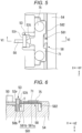
- FIG. 5 is a plan view as an enlarged view of the vicinity of the reflecting mirror 53.
- FIG. 6 is a cross-sectional view of the light source device 30 along the line VI-VI shown in FIG. 5 .
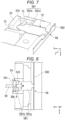
- FIG. 7 is a perspective view as an enlarged view of the vicinity of the pressing member 58.
- FIG. 8 is a plan view as an enlarged view of the vicinity of the pressing member 58. In FIG. 7 and FIG. 8 , in order to make the pressing member 58 eye-friendly, there is shown a state in which a holding member 71 is detached.
- the pressing member 58 has a pressing part 581 and an elastic part 582.
- the pressing member 58 is manufactured using a plate-like metal member having elasticity, and the pressing part 581 and the elastic part 582 are integrally formed. According to this configuration, it is possible to surely press the reflecting mirror 53 with the pressing part 581, and at the same time, it is possible to provide the pressing part 581 with a pressing force with the elastic part 582.
- the pressing part 581 has contact with the outer surface 53t of the reflecting mirror 53 to press the reflecting mirror 53.
- the pressing part 581 is formed of a plate-like member of which the thickness in the Y-axis direction is smaller than the width in the Z-axis direction.
- the pressing part 581 has a pressing part main body 581a, and a contact part 581b which extends from the pressing part main body 581a, and which has contact with the reflecting mirror 53.
- the planar shape of the pressing part main body 581a viewed from the Y-axis direction is a substantially rectangular shape.
- the contact part 581b is flared outward from substantially the center of a short side of the pressing part main body 581a, and the tip thereof has a semicircular shape.
- the contact part 581b has contact with the outer surface 53t of the reflecting mirror 53 with an extremely small area at the center of a semicircular arc. Therefore, the width in the Z-axis direction of the contact part 581b at a contact part P with the reflecting mirror 53 is sufficiently smaller than the width in the Z-axis direction of the pressing part main body 581a. In other words, the contact part 581b makes a substantially point contact with the outer surface 53t of the reflecting mirror 53.
- the shape of the contact part 581b can be, for example, a triangular shape besides the semicircular shape, and is preferably a shape making a substantially point contact with the outer surface 53t of the reflecting mirror 53.
- the elastic part 582 is a portion which is coupled to the pressing part 581, and is made elastically deformable and elastically restorable.
- the elastic part 582 extends long in the Z-axis direction in a state of being folded at substantially right angle from the pressing part 581.
- the elastic part 582 is formed of a plate-like member of which the thickness in the X-axis direction is sufficiently smaller than the width in the Z-axis direction and the height in the Y-axis direction. Therefore, the flexibility of the elastic part 582 in the X-axis direction is sufficiently higher than the flexibility of the elastic part 582 in the Y-axis direction and the Z-axis direction.
- the elastic part 582 is elastically deformable and elastically restorable in the X-axis direction, and functions as a plate spring for moving the pressing part 581 along the X-axis direction.
- both ends of the elastic part 582 are fixed to the support member 54 with fixation devices such as screws.
- the fixation with the screws or the like is not a limitation, and it is sufficient for the both ends of the elastic part 582 to be regulated in displacement toward the -X-axis direction. This is because, as described later in detail, the pressing part 581 is regulated in the Y-axis direction and the Z-axis direction with the holding member 71 and a regulatory groove part 72. Dimensions of parts of the pressing member 58 and an attachment position of the elastic part 582 are set in the state in which the pressing part 581 can always press the reflecting mirror 53.
- the reflecting mirror 53 and the pressing member 58 are formed of respective members separated from each other. According to this configuration, since the angle at which the reflecting mirror 53 and the pressing member 58 have contact with each other can freely change, it is possible to prevent the reflecting mirror 53 from tilting with respect to the wavelength conversion member 50 due to the influence of the tilt of the pressing member 58 even when the orientation of the pressing member 58 is somewhat tilted with respect to the reflecting mirror 53.
- the area of the reflecting surface 53r of the reflecting mirror 53 is larger than the area of the second face 50b of the wavelength conversion member 50. Thus, the circumferential edge part of the reflecting mirror 53 protrudes to the outside of the second face 50b of the wavelength conversion member 50. Thus, even when misalignment between the reflecting mirror 53 and the pressing member 58 occurs, it is possible to surely make the reflecting surface 53r of the reflecting mirror 53 have contact with the second face 50b of the wavelength conversion member 50.
- the contact position P of the contact part 581b with respect to the reflecting mirror 53 is located within a range of the width W in the Z-axis direction of the wavelength conversion member 50.
- the contact position P of the contact part 581b with respect to the reflecting mirror 53 is located within a range of the height T in the Y-axis direction of the wavelength conversion member 50.
- the contact position P of the contact part 581b with respect to the reflecting mirror 53 is located within a range of a region opposed to the second face 50b of the wavelength conversion member 50 out of the outer surface 53t of the reflecting mirror 53.
- the pressing member 58 presses the reflecting mirror 53
- the pressing force reaches the second face 50b of the wavelength conversion member 50 via the reflecting mirror 53, and therefore, the reflecting surface 53r is prevented from tilting with respect to the second face 50b, and the entire area of the reflecting surface 53r has contact with the entire area of the second face 50b.
- the holding member 71 there is disposed the holding member 71 at an opposite side to the support member 54 of the pressing member 58.
- the holding member 71 extends in the Z-axis direction, and at the same time, a central portion thereof has a shape of covering the pressing part main body 581a. Both end portions in the Z-axis direction of the holding member 71 are fixed to the support member 54 with screws 75.
- the holding member 71 regulates the translation of the pressing member 58 in the Y-axis direction.
- the holding member 71 is disposed at a slight distance from the pressing member 58.
- the holding member 71 in the present embodiment corresponds to a first regulatory part in the appended claims.
- the regulatory groove part 72 formed of a groove part extending in the X-axis direction is disposed at a position overlapping the pressing part main body 581a when viewed from the Y-axis direction.
- the width in the Z-axis direction of the regulatory groove part 72 is slightly larger than the width in the Z-axis direction of the pressing part main body 581a, and the depth in the Y-axis direction of the regulatory groove part 72 is larger than the plate thickness in the Y-axis direction of the pressing part main body 581a. Therefore, the pressing part main body 581a is housed inside the regulatory groove part 72.
- the pressing member 58 when the pressing member 58 is urged to move in the Z-axis direction, the pressing member 58 is not allowed to move since the pressing part main body 581a has contact with the side wall of the regulatory groove part 72.
- the regulatory groove part 72 regulates the translation of the pressing member 58 in the Z-axis direction.
- the regulatory groove part 72 in the present embodiment corresponds to a second regulatory part in the appended claims.
- the holding member 71 and the regulatory groove part 72 are disposed, the translation in the Y-axis direction and the translation in the Z-axis direction of the pressing member 58 are both regulated.
- the translation in the imaginary plane perpendicular to the X-axis direction of the pressing member 58 there is kept the state in which the contact position P of the contact part 581b with respect to the reflecting mirror 53 is located within the range of the region opposed to the second face 50b of the wavelength conversion member 50 out of the outer surface 53t of the reflecting mirror 53 without the contact position P being significantly translated.
- regulatory wall parts 73 opposed to end surfaces of the reflecting mirror 53 are disposed at both sides of the reflecting mirror 53 in the Z-axis direction.
- a distance between the two regulatory wall parts 73 is slightly larger than the width in the Z-axis direction of the reflecting mirror 53.
- the translation of the reflecting mirror 53 in the Y-axis direction is regulated by the support member 54 and the substrate 55 of the light source unit 51.
- the position of the reflecting mirror 53 is shifted in a direction perpendicular to the longitudinal direction of the wavelength conversion member 50 to make the reflecting mirror 53 run off the second face 50b of the wavelength conversion member 50.
- the regulatory wall parts 73, the support member 54, and the substrate 55 of the light source unit 51 in the present embodiment correspond to a third regulatory part in the appended claims.
- the pressing force of the pressing member 58 is set so as not to press the reflecting mirror 53 with an unnecessarily strong force.
- the force of the pressing member 58 pressing the reflecting mirror 53 in the X-axis direction is defined as F
- the force of the wavelength conversion member 50 pressing the support member 54 in the Y-axis direction with the fixation member 65 is defined as N
- the friction coefficient between the fourth face 40d of the wavelength conversion member 50 and the support surface 54s of the support member 54 is defined as ⁇ .
- the magnitude of the drag generated when the pressing member 58 presses the reflecting mirror 53 in the X-axis direction is obtained as N ⁇ .
- the pressing force In order to prevent the wavelength conversion member 50 from moving in the X-axis direction when the pressing member 58 presses the reflecting mirror 53, it is sufficient for the pressing force to be weaker than the drag. In other words, it is sufficient to fulfill the relationship of F ⁇ N ⁇ .
- the distance between the angle conversion member 52 and the optical system in the posterior stage varies, and therefore, there is a possibility that there occurs the fluorescence Y which fails to enter the optical system in the posterior stage.
- the wavelength conversion member 50 does not move in the X-axis direction, it is possible to suppress the loss of the fluorescence Y due to the translation in the X-axis direction of the wavelength conversion member 50.
- no mechanical stress is applied to the angle conversion member 52 unlike the configuration in which the translation in the X-axis direction of the wavelength conversion member 50 is regulated by physically fixing the angle conversion member 52, it is possible to extract the fluorescence Y having the desired intensity.
- the light source device 30 is provided with the light emitting elements 56 for emitting the excitation light E, the wavelength conversion member 50 for converting the excitation light E emitted from the light emitting elements 56 into the fluorescence Y and then emitting the fluorescence Y, the reflecting mirror 53 having the reflecting surface 53r for reflecting the fluorescence Y proceeding through the wavelength conversion member 50, and the pressing member 58 for pressing the reflecting mirror 53 toward the wavelength conversion member 50.
- the wavelength conversion member 50 has the first face 50a and the second face 50b located at the respective sides opposed to each other in the X-axis direction, and the third face 50c and the fourth face 50d located at the respective sides opposed to each other in the Y-axis direction.
- the fluorescence Y guided in the wavelength conversion member 50 is emitted from the first face 50a.
- the light emitting elements 56 are disposed so as to be opposed to the third face 50c.
- the second face 50b and the reflecting surface 53r have contact with each other, and the pressing member 58 presses the reflecting mirror 53 from the outer surface 53t of the reflecting mirror 53 toward the second face 50b.
- the reflecting mirror 53 is disposed at a position distance from the wavelength conversion member 50.
- the proportion of the fluorescence Y proceeding in a direction of running off the wavelength conversion member 50 is high, and the loss of the fluorescence Y increases.
- the reflecting mirror 53 is pressed by the pressing member 58 against the second face 50b of the wavelength conversion member 50. Therefore, the fluorescence Y having reached the second face 50b is reflected by the reflecting surface 53r, and then proceeds toward the first face 50a while repeating the total reflection inside the wavelength conversion member 50.
- the loss of the fluorescence Y it is possible to suppress the loss of the fluorescence Y to a sufficiently low level, and thus, it is possible to obtain the fluorescence Y having the desired intensity.
- the reflecting mirror As a method of making the reflecting mirror have contact with the wavelength conversion member, it is conceivable that, for example, the reflecting mirror is fixed at a specific position in the support member to thereby make the reflecting mirror have contact with the wavelength conversion member.
- the wavelength conversion member expands or contracts in the longitudinal direction due to the change in temperature. Therefore, when the reflecting mirror is supposedly fixed at the specific position in the support member, there is a possibility that the wavelength conversion member and the reflecting mirror become separated from each other when the wavelength conversion member contracts due to, for example, the change in temperature.
- the reflecting mirror 53 is always pressed against the wavelength conversion member 50, even when the wavelength conversion member 50 contracts, the reflecting mirror 53 moves following the contraction of the wavelength conversion member 50, and the state of having contact with the wavelength conversion member 50 is kept. On the other hand, even when the wavelength conversion member 50 expands, the pressing member 58 makes the elastic deformation, and therefore, no failure occurs. Thus, it is possible to stably obtain the fluorescence Y having the desired intensity.
- the reflecting mirror As another method of making the reflecting mirror have contact with the wavelength conversion member, it is conceivable to bond the reflecting mirror to the wavelength conversion member using an adhesive.
- an adhesive In this configuration, there is a problem that a part of the fluorescence is absorbed by the adhesive, and thus, the loss of the fluorescence increases. Further, there is a problem that when the temperature of the wavelength conversion member rises, a deflection occurs in the bonded interface due to a difference between the thermal expansion coefficient of the wavelength conversion member and the thermal expansion coefficient of the reflecting mirror.
- the light source device 30 related to the present embodiment since no adhesive intervenes between the reflecting mirror 53 and the wavelength conversion member 50, and the reflecting mirror 53 and the wavelength conversion member 50 can individually expand or contract, it is possible to resolve the problem described above.
- the projector 1 according to the present embodiment is equipped with the light source device 30 according to the present embodiment, and is therefore excellent in display quality.
- the reflecting mirror and the pressing member are formed of the respective members separated from each other, but instead of this configuration, it is possible to adopt a configuration in which the reflecting mirror and the pressing member are formed of an integrated member. According to this configuration, it is possible to reduce the number of components of the light source device, and thus, it is possible to simplify the assembling process of the light source device.
- the pressing member has the plate spring structure in the embodiment described above, but it is sufficient for the pressing member to be a member capable of exerting the elasticity in the X-axis direction, and it is possible for the pressing member to have other spring structures such as a coil spring.
- each of the wall surfaces of the groove part of the support member has a portion perpendicular to the support surface and a portion tilted with respect to the support surface, but the shape of the groove part is not particularly limited, and for example, all of the areas of the wall surfaces of the groove part can be perpendicular to the support surface. Further, the wall surfaces of the groove part can be curved.
- the present disclosure is applied to the light source device provided with the wavelength conversion member, but instead of this configuration, it is possible to apply the present disclosure to a light source device which propagates the incident light without the wavelength conversion, and then emits the incident light controlling, for example, the angular distribution.
- the wavelength conversion member of the embodiment described above is replaced with a light guide member, and the light emitted from the light emitting element is emitted from the angle conversion member as light in an unchanged wavelength band.
- the specific descriptions of the shape, the number, the arrangement, the material, and so on of the constituents of the light source device and the projector are not limited to those in the embodiment described above, and can arbitrarily be modified.
- the example of installing the light source device according to the present disclosure in the projector using the liquid crystal panels the example is not a limitation.
- the light source device according to the present disclosure can also be applied to a projector using digital micromirror devices as the light modulation devices.
- the projector is not required to have a plurality of light modulation devices, and can be provided with just one light modulation device.
- the example is not a limitation.
- the light source device according to the present disclosure can also be applied to lighting equipment, a headlight of a vehicle, and so on.
- a light source device including a light emitting element configured to emit light, a light guide member configured to guide the light emitted from the light emitting element, a reflecting member having a reflecting surface configured to reflect the light proceeding through the light guide member, and a pressing member configured to press the reflecting member against the light guide member
- the light guide member includes a first face and a second face located at respective sides opposite to each other in a first direction as a longitudinal direction of the light guide member, and a third face and a fourth face located at respective sides opposite to each other in a second direction in an imaginary plane perpendicular to the first direction
- the light guided through the light guide member is emitted from the first face
- the light emitting element is disposed so as to be opposed to the third face
- the second face and the reflecting surface have contact with each other
- the pressing member is configured to press the reflecting member from a surface at an opposite side to the reflecting surface of the reflecting member toward the second face.
- the pressing member includes a pressing part configured to press the reflecting member, and an elastic part which is coupled to the pressing part, and which is elastically deformable and elastically restorable, and flexibility of the elastic part in the first direction is higher than flexibility of the elastic part in the second direction and a third direction perpendicular to the second direction in the imaginary plane.
- the pressing part has a pressing part main body, and a contact part which extends from the pressing part main body, and which is configured to have contact with the reflecting member, and a contact position of the contact part with respect to the reflecting member is located within a range of a region opposed to the second face of the light guide member out of a surface at a side opposite to the reflecting surface of the reflecting member.
- the light source device described in Supplementary Note 4 further including a first regulatory part configured to regulate a translation of the pressing member in the second direction.
- the pressing part is formed of a plate-like member of which a thickness in the second direction is smaller than a width in a third direction perpendicular to the second direction in the imaginary plane, and a width in the third direction of the contact part at the contact position is smaller than a width in the third direction of the pressing part main body.
- the light emitting element is configured to emit first light having a first wavelength band
- the light guide member is a wavelength conversion member which includes a phosphor, and which is configured to convert the first light emitted from the light emitting element into second light having a second wavelength band different from the first wavelength band to emit the second light.
- a projector including the light source device described in any one of Supplementary Note 1 through Supplementary Note 13, a light modulation device configured to modulate the light emitted from the light source device in accordance with image information, and a projection optical device configured to project the light modulated by the light modulation device.
Landscapes
- Physics & Mathematics (AREA)
- General Physics & Mathematics (AREA)
- Optics & Photonics (AREA)
- Engineering & Computer Science (AREA)
- Multimedia (AREA)
- Non-Portable Lighting Devices Or Systems Thereof (AREA)
- Projection Apparatus (AREA)
- Planar Illumination Modules (AREA)
- Transforming Electric Information Into Light Information (AREA)
Abstract
Description
- The present application is based on, and claims priority from
JP Application Serial Number 2023-016077, filed February 6, 2023 - The present disclosure relates to a light source device and a projector.
- As a light source device used for a projector, there is proposed a light source device using fluorescence emitted from a phosphor when irradiating the phosphor with excitation light emitted from a light emitting element.
- In International Patent Publication No.
WO 2021/510912 , there is disclosed a light source device provided with a light source for emitting blue excitation light, a phosphor rod for converting the excitation light into fluorescence, and a mirror for returning the fluorescence emitted from a surface at an opposite side to an exit surface of the phosphor rod. - In the light source device in
WO 2021/510912 , the mirror is disposed at a position distant from the phosphor rod. In this configuration, a proportion of the fluorescence reflected toward a direction deviated from the phosphor rod to the fluorescence emitted from the phosphor rod is high. Therefore, it is difficult to sufficiently return the fluorescence to the phosphor rod, and there is a problem that the loss of the fluorescence increases. - Although the description is hereinabove presented citing the light source device accompanied by a wavelength conversion as an example, there is substantially the same problem also in a light source device not accompanied by the wavelength conversion. It is desired to provide the light source device which is low in loss of the output light, and which is capable of emitting the light having a desired intensity.
- In view of the problems described above, the light source device according to an aspect of the present disclosure includes a light emitting element configured to emit light, a light guide member configured to guide the light emitted from the light emitting element, a reflecting member having a reflecting surface configured to reflect the light proceeding through the light guide member, and a pressing member configured to press the reflecting member against the light guide member. The light guide member includes a first face and a second face located at respective sides opposite to each other in a first direction as a longitudinal direction of the light guide member, and a third face and a fourth face located at respective sides opposite to each other in a second direction in an imaginary plane perpendicular to the first direction. The light guided through the light guide member is emitted from the first face. The light emitting element is disposed so as to be opposed to the third face. The second face and the reflecting surface have contact with each other, and the pressing member is configured to press the reflecting member from a surface at an opposite side to the reflecting surface of the reflecting member toward the second face.
- A projector according to an aspect of the present disclosure includes the light source device according to one of the aspects of the present disclosure, a light modulation device configured to modulate the light emitted from the light source device in accordance with image information, and a projection optical device configured to project the light modulated by the light modulation device.
-
-
FIG. 1 is a schematic configuration diagram of a projector according to an embodiment. -
FIG. 2 is a schematic configuration diagram of a first illumination device according to the embodiment. -
FIG. 3 is a perspective view of a light source device according to the embodiment. -
FIG. 4 is a cross-sectional view of the light source device along the line IV-IV shown inFIG. 3 . -
FIG. 5 is a plan view as an enlarged view of the vicinity of a reflecting member. -
FIG. 6 is a cross-sectional view of the light source device along the line VI-VI shown inFIG. 5 . -
FIG. 7 is a perspective view as an enlarged view of the vicinity of a pressing member. -
FIG. 8 is a plan view as an enlarged view of the vicinity of the pressing member. -
FIG. 9 is a diagram showing a problem of a related-art light source device. -
FIG. 10 is a diagram showing another problem of the related-art light source device. -
FIG. 11 is a diagram showing an advantage of the light source device according to the present embodiment. - A first embodiment of the present disclosure will hereinafter be described using the drawings.
- A projector according to the present embodiment is an example of a projector using liquid crystal panels as light modulation devices.
- In the drawings described below, constituents are shown with respective dimensional scale ratios different from each other in some cases in order to make the constituents eye-friendly.
-
FIG. 1 is a diagram showing a schematic configuration of aprojector 1 according to the present embodiment. - As shown in
FIG. 1 , theprojector 1 according to the present embodiment is a projection-type image display device for displaying a color image on a screen (a projection target surface) SCR. Theprojector 1 is provided with three light modulation devices corresponding to respective colored light, namely red light LR, green light LG, and blue light LB. - The
projector 1 is provided with afirst illumination device 20, asecond illumination device 21, a color separation optical system 3, alight modulation device 4R, alight modulation device 4G, alight modulation device 4B, alight combining element 5, and a projectionoptical device 6. - The
first illumination device 20 emits fluorescence Y having a yellow color toward the color separation optical system 3. Thesecond illumination device 21 emits the blue light LB toward thelight modulation device 4B. The detailed configurations of thefirst illumination device 20 and thesecond illumination device 21 will be described later. - Hereinafter, in the drawings, the explanation will be presented using an XYZ orthogonal coordinate system as needed. A Z axis is an axis along a vertical direction of the
projector 1. An X axis is an axis parallel to an optical axis AX1 of thefirst illumination device 20 and an optical axis AX2 of thesecond illumination device 21, and is an axis along a front-back direction of theprojector 1. The Y axis is an axis perpendicular to the X axis and the Z axis, and is an axis along a horizontal direction of theprojector 1. These representations are for explaining a layout relationship of the constituent members of theprojector 1, but are not for limiting the installation posture and the direction of theprojector 1. The optical axis AX1 of thefirst illumination device 20 is a central axis of the fluorescence Y emitted from thefirst illumination device 20. The optical axis AX2 of thesecond illumination device 21 is a central axis of the blue light LB emitted from thesecond illumination device 21. - The color separation optical system 3 separates the fluorescence Y having the yellow color emitted from the
first illumination device 20 into the red light LR and the green light LG. The color separation optical system 3 is provided with adichroic mirror 7, a first reflectingmirror 8a, and a second reflectingmirror 8b. - The
dichroic mirror 7 separates the fluorescence Y into the red light LR and the green light LG. Thedichroic mirror 7 transmits the red light LR, and at the same time, reflects the green light LG. The second reflectingmirror 8b is arranged in a light path of the green light LG. The second reflectingmirror 8b reflects the green light LG, which has been reflected by thedichroic mirror 7, toward thelight modulation device 4G. The first reflectingmirror 8a is arranged in a light path of the red light LR. The first reflectingmirror 8a reflects the red light LR, which has been transmitted through thedichroic mirror 7, toward thelight modulation device 4R. - Meanwhile, the blue light LB emitted from the
second illumination device 21 is reflected by a reflectingmirror 9 toward thelight modulation device 4B. - The configuration of the
second illumination device 21 will hereinafter be described. - The
second illumination device 21 is provided with alight source unit 81, acondenser lens 82, adiffuser plate 83, arod lens 86, and arelay lens 87. Thelight source unit 81 is formed of at least one semiconductor laser. Thelight source unit 81 emits the blue light LB consisting of a laser beam. It should be noted that thelight source unit 81 can also be formed of an LED for emitting blue light besides the semiconductor laser. - The
condenser lens 82 is formed of a convex lens. Thecondenser lens 82 makes the blue light LB emitted from thelight source unit 81 enter thediffuser plate 83 in a state of being substantially converged. Thediffuser plate 83 diffuses the blue light LB emitted from thecondenser lens 82 at a predetermined diffusion angle to generate the blue light LB having a substantially homogenous light distribution similarly to the fluorescence Y emitted from thefirst illumination device 20. As thediffuser plate 83, there is used, for example, frosted glass made of optical glass. - The blue light LB diffused by the
diffuser plate 83 enters therod lens 86. Therod lens 86 has a prismatic shape extending along a direction of the optical axis AX2 of thesecond illumination device 21. Therod lens 86 has a lightincidence end plane 86a, and a lightexit end surface 86b located at an opposite side to the lightincidence end plane 86a. Thediffuser plate 83 is fixed to the lightincidence end plane 86a of therod lens 86 via an optical adhesive (not shown). It is desirable to make the refractive index of thediffuser plate 83 and the refractive index of therod lens 86 coincide with each other as precise as possible. - The blue light LB is emitted from the light
exit end surface 86b in the state in which homogeneity of an illuminance distribution is enhanced by propagating through therod lens 86 while being totally reflected. The blue light LB emitted from therod lens 86 enters therelay lens 87. Therelay lens 87 makes the blue light LB having been enhanced in homogeneity of the illuminance distribution by therod lens 86 enter the reflectingmirror 9. - The shape of the light
exit end surface 86b of therod lens 86 is a rectangular shape substantially similar to a shape of an image formation area of thelight modulation device 4B. Thus, the blue light LB emitted from therod lens 86 efficiently enters the image formation area of thelight modulation device 4B. - The
light modulation device 4R modulates the red light LR in accordance with image information to form image light corresponding to the red light LR. Thelight modulation device 4G modulates the green light LG in accordance with the image information to form image light corresponding to the green light LG. Thelight modulation device 4B modulates the blue light LB in accordance with the image information to form image light corresponding to the blue light LB. - In each of the
light modulation devices - At the incident side of the
light modulation device 4R, there is arranged afield lens 10R. At the incident side of thelight modulation device 4G, there is arranged afield lens 10G. At the incident side of thelight modulation device 4B, there is arranged afield lens 10B. Thefield lens 10R collimates a principal ray of the red light LR entering thelight modulation device 4R. Thefield lens 10G collimates a principal ray of the green light LG entering thelight modulation device 4G. Thefield lens 10B collimates a principal ray of the blue light LB entering thelight modulation device 4B. - The
light combining element 5 combines the image light corresponding to the red light LR, the image light corresponding to the green light LG, and the image light corresponding to the blue light LB with each other in response to incidence of the image light emitted from thelight modulation device 4R, the image light emitted from thelight modulation device 4G, and the image light emitted from thelight modulation device 4B, and then emits the image light thus combined toward the projectionoptical device 6. As thelight combining element 5, there is used, for example, a cross dichroic prism. - The projection
optical device 6 is constituted by a plurality of projection lenses. The projectionoptical device 6 projects the image light having been combined by thelight combining element 5 toward the screen SCR in an enlarged manner. Thus, an image is displayed on the screen SCR. - A configuration of the
first illumination device 20 will hereinafter be described. -
FIG. 2 is a schematic diagram showing a general configuration of thefirst illumination device 20. - As shown in
FIG. 2 , thefirst illumination device 20 is provided with alight source device 30, a collimatingoptical system 63, an integratoroptical system 31, apolarization conversion element 32, and a superimposingoptical system 33. -
FIG. 3 is a perspective view of thelight source device 30, and shows a state in which some of the members are exploded. - As shown in
FIG. 2 andFIG. 3 , thelight source device 30 is provided with awavelength conversion member 50, alight source unit 51, asupport member 54, afixation member 65, a reflectingmirror 53, a pressingmember 58, and anangle conversion member 52. Thelight source unit 51 is provided with asubstrate 55 andlight emitting elements 56. - The reflecting
mirror 53 in the present embodiment corresponds to a reflecting member in the appended claims. Thewavelength conversion member 50 in the present embodiment corresponds to a light guide member in the appended claims. - The
wavelength conversion member 50 has a quadrangular prismatic shape extending in the X-axis direction, and has six faces. A side extending in the X-axis direction of thewavelength conversion member 50 is longer than a side extending in the Y-axis direction and a side extending in the Z-axis direction. In other words, the X-axis direction corresponds to a longitudinal direction of thewavelength conversion member 50. The length of the side extending in the Y-axis direction and the length of the side extending in the Z-axis direction are equal to each other. In other words, a cross-sectional shape of thewavelength conversion member 50 cut by a plane perpendicular to the X-axis direction is a square. It should be noted that the cross-sectional shape of thewavelength conversion member 50 cut by the plane perpendicular to the X-axis direction can be a rectangle. - The
wavelength conversion member 50 has afirst face 50a and asecond face 50b, athird face 50c and a fourth face50d, and afifth face 50e and asixth face 50f. Thefirst face 50a and thesecond face 50b cross the longitudinal direction (the X-axis direction) of thewavelength conversion member 50, and are located at respective sides opposite to each other. Thethird face 50c and thefourth face 50d cross thefirst face 50a and thesecond face 50b, and are located at respective sides opposite to each other in the Y-axis direction in an imaginary plane perpendicular to the longitudinal direction. Thefifth face 50e and thesixth face 50f cross thethird face 50c and thefourth face 50d, and are located at respective sides opposite to each other in the Z-axis direction in the imaginary plane perpendicular to the longitudinal direction. In the following description, thethird face 50c, thefourth face 50d, thefifth face 50e, and thesixth face 50f are collectively referred to as side surfaces in some cases. The X-axis direction in the present embodiment corresponds to a first direction in the appended claims. The Y-axis direction in the present embodiment corresponds to a second direction in the appended claims. The Z-axis direction in the present embodiment corresponds to a third direction in the appended claims. - The
wavelength conversion member 50 includes a phosphor, and converts excitation light E having a first wavelength band into the fluorescence Y having a second wavelength band different from the first wavelength band. The excitation light E enters thewavelength conversion member 50 from thethird face 50c. The fluorescence Y is guided inside thewavelength conversion member 50, and is then emitted from thefirst face 50a. The excitation light E in the present embodiment corresponds to first light in the appended claims. The fluorescence Y in the present embodiment corresponds to second light in the appended claims. - The
wavelength conversion member 50 includes a ceramic phosphor made of a polycrystalline phosphor for wavelength-converting the excitation light E into the fluorescence Y. The second wavelength band which the fluorescence Y has is a yellow wavelength band of, for example, 490 through 750 nm. In other words, the fluorescence Y is yellow fluorescence including a red light component and a green light component. - It is also possible for the
wavelength conversion member 50 to include a single-crystal phosphor instead of the polycrystalline phosphor. Alternatively, thewavelength conversion member 50 can also be formed of fluorescent glass. Alternatively, thewavelength conversion member 50 can also be formed of a material obtained by dispersing a number of phosphor particles in a binder made of glass or resin. Thewavelength conversion member 50 made of such a material converts the excitation light E in the first wavelength band into the fluorescence Y in the second wavelength band. - Specifically, the material of the
wavelength conversion member 50 includes, for example, an yttrium aluminum garnet (YAG) phosphor. Citing YAG:Ce including cerium (Ce) as an activator agent as an example, as the material of thewavelength conversion member 50, there is used a material obtained by mixing raw powder including constituent elements such as Y2O3, Al2O3, and CeO3 to cause the solid-phase reaction, Y-Al-O amorphous particles obtained by a wet process such as a coprecipitation process or a sol-gel process, and YAG particles obtained by a gas-phase process such as a spray drying process, a flame heat decomposition process, or a thermal plasma process. - The
light source unit 51 is provided with thelight emitting elements 56 for emitting the excitation light E in the first wavelength band. Thelight emitting elements 56 are each formed of, for example, a light emitting diode (LED). Thelight emitting elements 56 are disposed so as to be opposed to thethird face 50c of thewavelength conversion member 50. Thelight emitting elements 56 emit the excitation light E toward thethird face 50c. The first wavelength band is a wavelength band from a blue color to a violet color of, for example, 400 nm through 480 nm, and has a peak wavelength of, for example, 445 nm. As described above, thelight source unit 51 is disposed so as to be opposed to one of the four side surfaces along the longitudinal direction of thewavelength conversion member 50. - The
substrate 55 supports thelight emitting elements 56. Thelight source unit 51 is constituted by thelight emitting elements 56 and thesubstrate 55 in the case of the present embodiment, but can also be provided with other optical members such as a light guide plate, a diffuser plate, or a lens besides the above. Although the plurality oflight emitting elements 56 are used in the present embodiment, the number of thelight emitting elements 56 is not particularly limited. - The
support member 54 is disposed so as to surround thefourth face 50d, thefifth face 50e, and thesixth face 50f of thewavelength conversion member 50. Thesupport member 54 supports thewavelength conversion member 50, and diffuses the heat generated in thewavelength conversion member 50 to release the heat to an outside space. Therefore, it is desirable for thesupport member 54 to be formed of a material which has predetermined strength and is high in thermal conductivity. As the material of thesupport member 54, there is used metal such as aluminum or stainless steel, and in particular, an aluminum alloy such as 6061 aluminum alloy is preferably used. -
FIG. 4 is a cross-sectional view of thelight source device 30 along the line IV-IV shown inFIG. 3 . - As shown in
FIG. 3 and FIG. 4 , thesupport member 54 has agroove part 54h which extends in the longitudinal direction (the X-axis direction) of thewavelength conversion member 50, and which houses thewavelength conversion member 50. Thesupport member 54 has thegroove part 54h, and therefore, a cross-sectional surface perpendicular to the X-axis direction of thesupport member 54 has a U-shape. Thegroove part 54h has asupport surface 54s, afirst wall surface 54a, and asecond wall surface 54b. - The
support surface 54s corresponds to a bottom surface of thegroove part 54h, and has contact with thefourth face 50d of thewavelength conversion member 50. Thefirst wall surface 54a corresponds to one of side surfaces of thegroove part 54h, and is opposed to thefifth face 50e of thewavelength conversion member 50, and is separated from thefifth face 50e. Thesecond wall surface 54b corresponds to the other of the side surfaces of thegroove part 54h, and is opposed to thesixth face 50f of thewavelength conversion member 50, and is separated from thesixth face 50f. In other words, a gap is disposed between thefirst wall surface 54a and thefifth face 50e of thewavelength conversion member 50. A gap is disposed between thesecond wall surface 54b and thesixth face 50f of thewavelength conversion member 50. - The
first wall surface 54a has a first portion 54a1 located at thethird face 50c side, and a second portion 54a2 located at thesupport surface 54s side. The first portion 54a1 extends in a direction perpendicular to thesupport surface 54s, namely in parallel to the X-Y plane. The second portion 54a2 is tilted so as to come closer to thefifth face 50e in a direction from the first portion 54a1 toward thesupport surface 54s. In other words, a distance between the second portion 54a2 and thefifth face 50e at thesupport surface 54s side is shorter than a distance between the second portion 54a2 and thefifth face 50e at the first portion 54a1 side. - The
second wall surface 54b has a third portion 54b3 located at thethird face 50c side, and a fourth portion 54b4 located at thesupport surface 54s side. The third portion 54b3 extends in a direction perpendicular to thesupport surface 54s, namely in parallel to the X-Y plane. The fourth portion 54b4 is tilted so as to come closer to thesixth face 50f in a direction from the third portion 54b3 toward thesupport surface 54s. In other words, a distance between the fourth portion 54b4 and thesixth face 50f at thesupport surface 54s side is shorter than a distance between the fourth portion 54b4 and thesixth face 50f at the third portion 54b3 side. - Each of the
support surface 54s, thefirst wall surface 54a, and thesecond wall surface 54b is formed of a surface of metal such as aluminum or stainless steel as the constituent material of thesupport member 54. More specifically, each of thesupport surface 54s, thefirst wall surface 54a, and thesecond wall surface 54b is formed of a processed surface obtained by performing mirror finish on the metal surface described above. Therefore, each of thesupport surface 54s, thefirst wall surface 54a, and thesecond wall surface 54b has light reflectivity, and reflects the excitation light E having entered thesupport surface 54s, thefirst wall surface 54a, or thesecond wall surface 54b. It should be noted that each of thesupport surface 54s, thefirst wall surface 54a, and thesecond wall surface 54b can be formed of another metal film or another dielectric multilayer film formed on a surface of metal such as aluminum or stainless steel. - Most of the excitation light E emitted from the
light emitting elements 56 enters thewavelength conversion member 50 from thethird face 50c. Further, the excitation light E1 which is emitted from thelight emitting elements 56, and then enters the gap between thefirst wall surface 54a and thefifth face 50e, or the gap between thesecond wall surface 54b and thesixth face 50f is reflected by thefirst wall surface 54a or thesecond wall surface 54b, and then enters thewavelength conversion member 50 from thefifth face 50e or thesixth face 50f. In the case of the present embodiment, since the second portion 54a2 and the fourth portion 54b4 tilted with respect to the X-Y plane are disposed, it is possible to increase the proportion of the excitation light E1 which enters thefifth face 50e or thesixth face 50f to the excitation light E1 which is reflected by thefirst wall surface 54a or thesecond wall surface 54b. - As shown in
FIG. 4 , thefixation member 65 is disposed so as to be opposed to thethird face 50c of thewavelength conversion member 50. Thefixation member 65 is formed of, for example, a plate spring which is elastically deformable. As shown inFIG. 3 , thefixation member 65 is arranged so as to extend in a direction (the Z-axis direction) perpendicular to the longitudinal direction of thewavelength conversion member 50, and both ends of thefixation member 65 are fixed to thesupport member 54 withscrews 70. Thefixation member 65 fixes thewavelength conversion member 50 to thesupport member 54 in a state of being pressed from thethird face 50c toward thesupport surface 54s of thesupport member 54. Thus, thewavelength conversion member 50 surely adheres to thesupport member 54. It should be noted that it is sufficient for thefixation member 65 to be able to press thewavelength conversion member 50 from thethird face 50c toward thesupport surface 54s of thesupport member 54, and it is possible to adopt, for example, a protruding part which is provided to thesubstrate 55 of thelight source unit 51, and protrudes toward thewavelength conversion member 50, instead of the configuration of the present embodiment. - As shown in
FIG. 2 , the reflectingmirror 53 is disposed so as to have contact with thesecond face 50b of thewavelength conversion member 50. The reflectingmirror 53 has a reflectingsurface 53r for reflecting the fluorescence Y proceeding through thewavelength conversion member 50, and anouter surface 53t at an opposite side to the reflectingsurface 53r. The reflectingmirror 53 reflects the fluorescence Y which has been guided inside thewavelength conversion member 50, and which has reached thesecond face 50b, with the reflectingsurface 53r. The reflectingmirror 53 is constituted by a substrate such as glass, and a reflecting film such as a metal film or a dielectric multilayer film formed on one surface of the substrate. In other words, the reflectingsurface 53r is constituted by a reflecting film formed of the metal film, the dielectric multilayer film, or the like. - When the excitation light E emitted from the
light emitting elements 56 enters thewavelength conversion member 50, the phosphor included in thewavelength conversion member 50 is excited, and the fluorescence Y is emitted from an arbitrary light emitting point. The fluorescence Y proceeds from the arbitrary light emitting point toward all directions, but the fluorescence Y having proceeded toward the fourside surfaces first face 50a or thesecond face 50b. The fluorescence Y proceeding toward thefirst face 50a enters theangle conversion member 52. The fluorescence Y having proceeded toward thesecond face 50b is reflected by the reflectingmirror 53, and then proceeds toward thefirst face 50a. - A part of the excitation light E which has not been used for the excitation of the phosphor out of the excitation light E having entered the
wavelength conversion member 50 is reflected by a member on the periphery of thewavelength conversion member 50 including thelight emitting elements 56 of thelight source unit 51, or the reflectingmirror 53 disposed on thesecond face 50b. Therefore, the part of the excitation light E is confined inside thewavelength conversion member 50 to be reused. - The pressing
member 58 presses the reflectingmirror 53 from theouter surface 53t side toward thesecond face 50b of thewavelength conversion member 50. Thus, the reflectingsurface 53r of the reflectingmirror 53 adheres to thesecond face 50b of thewavelength conversion member 50. The detailed configuration of the pressingmember 58 will be described later. - The
angle conversion member 52 is disposed at the light exit side of thefirst face 50a of thewavelength conversion member 50. Theangle conversion member 52 is formed of, for example, a compound parabolic concentrator (CPC). Theangle conversion member 52 has a plane of incidence of light 52a which the fluorescence Y emitted from thewavelength conversion member 50 enters, alight exit surface 52b for emitting the fluorescence Y, and aside surface 52c for reflecting the fluorescence Y having entered theside surface 52c, toward thelight exit surface 52b. - The cross-sectional area perpendicular to an optical axis J of the
angle conversion member 52 increases in a direction from the plane of incidence of light 52a toward thelight exit surface 52b. Therefore, the area of thelight exit surface 52b is larger than the area of the plane of incidence of light 52a. An axis which passes through the center of thelight exit surface 52b and the center of the plane of incidence of light 52a, and which is parallel to the X axis, is defined as the optical axis J of theangle conversion member 52. The optical axis J of theangle conversion member 52 coincides with the optical axis AX1 of thefirst illumination device 20. - The fluorescence Y having entered the
angle conversion member 52 changes the direction so as to approximate to a direction parallel to the optical axis J when the fluorescence Y is totally reflected by theside surface 52c while proceeding inside theangle conversion member 52. In such a manner, theangle conversion member 52 converts an exit angle distribution of the fluorescence Y emitted from thefirst face 50a of thewavelength conversion member 50. Specifically, theangle conversion member 52 makes a maximum exit angle of the fluorescence Y on thelight exit surface 52b smaller than a maximum incident angle of the fluorescence Y on the plane of incidence of light 52a. - In general, since an etendue of light defined by a product of the area of a light exit region and a solid angle (the maximum exit angle) of the light is conserved, the etendue of the fluorescence Y is also conserved before and after the transmission through the
angle conversion member 52. As described above, theangle conversion member 52 has the configuration in which the area of thelight exit surface 52b is made larger than the area of the plane of incidence of light 52a. Therefore, in view of the conservation of the etendue, it is possible for theangle conversion member 52 to make the maximum exit angle of the fluorescence Y on thelight exit surface 52b smaller than the maximum incident angle of the fluorescence Y on the plane of incidence of light 52a. - The
angle conversion member 52 is fixed to thewavelength conversion member 50 via an optical adhesive (not shown) so that the plane of incidence of light 52a is opposed to thefirst face 50a of thewavelength conversion member 50. Specifically, theangle conversion member 52 and thewavelength conversion member 50 have contact with each other via the optical adhesive, and no air gap (no air layer) is disposed between theangle conversion member 52 and thewavelength conversion member 50. When an air gap is supposedly disposed between theangle conversion member 52 and thewavelength conversion member 50, the fluorescence Y having entered the plane of incidence of light 52a of theangle conversion member 52 at an angle no smaller than a critical angle out of the fluorescence Y having reached the plane of incidence of light 52a of theangle conversion member 52 is totally reflected by the plane of incidence of light 52a, and fails to enter theangle conversion member 52. In contrast, when such an air gap is not disposed between theangle conversion member 52 and thewavelength conversion member 50 as in the present embodiment, it is possible to reduce the fluorescence Y which cannot enter theangle conversion member 52. From this point of view, it is desirable to make the refractive index of theangle conversion member 52 and the refractive index of thewavelength conversion member 50 coincide with each other as precisely as possible. - A taper rod having, for example, a truncated quadrangular pyramid-like shape can be used as the
angle conversion member 52 instead of the CPC. Even when using the taper rod as theangle conversion member 52, it is also possible to obtain substantially the same advantages as those obtained when using the CPC. It should be noted that thelight source device 30 is not necessarily required to be provided with theangle conversion member 52. - The collimating
optical system 63 formed of a collimator lens and so on is disposed between thelight source device 30 and the integratoroptical system 31. The collimatingoptical system 63 makes the angle distribution of the fluorescence Y emitted from theangle conversion member 52 smaller, and then makes the fluorescence Y high in parallelism enter the integratoroptical system 31. It should be noted that the collimatingoptical system 63 is not required to be disposed when the parallelism of the fluorescence Y emitted from theangle conversion member 52 is sufficiently high. - The integrator
optical system 31 has afirst lens array 61 and asecond lens array 62. The integratoroptical system 31 functions as a homogenous illumination optical system for homogenizing an intensity distribution of the fluorescence Y emitted from thelight source device 30 in each of thelight modulation devices optical system 33. The fluorescence Y emitted from the collimatingoptical system 63 enters thefirst lens array 61. Thefirst lens array 61 constitutes the integratoroptical system 31 together with thesecond lens array 62 disposed in a posterior stage of thelight source device 30. - The
first lens array 61 has a plurality offirst lenses 61a. The plurality offirst lenses 61a are arranged in a matrix in a plane parallel to the Y-Z plane perpendicular to the optical axis AX1 of thefirst illumination device 20. The plurality offirst lenses 61a divide the fluorescence Y emitted from theangle conversion member 52 into a plurality of partial light beams. A shape of each of thefirst lenses 61a is a rectangular shape substantially similar to a shape of each of the image formation areas of thelight modulation devices first lens array 61 efficiently enters each of the image formation areas of thelight modulation devices - The fluorescence Y emitted from the
first lens array 61 proceeds toward thesecond lens array 62. Thesecond lens array 62 is arranged so as to be opposed to thefirst lens array 61. Thesecond lens array 62 has a plurality ofsecond lenses 62a corresponding respectively to the plurality offirst lenses 61a of thefirst lens array 61. Thesecond lens array 62 forms each of images of the plurality offirst lenses 61a of thefirst lens array 61 in the vicinity of each of the image formation areas of thelight modulation devices optical system 33. The plurality ofsecond lenses 62a are arranged in a matrix in a plane parallel to the Y-Z plane perpendicular to the optical axis AX1 of thefirst illumination device 20. - Each of the
first lenses 61a of thefirst lens array 61 and each of thesecond lenses 62a of thesecond lens array 62 have respective sizes the same as each other in the present embodiment, but can have respective sizes different from each other. Further, thefirst lenses 61a of thefirst lens array 61 and thesecond lenses 62a of thesecond lens array 62 are arranged at positions where respective optical axes coincide with each other in the present embodiment, but can be arranged in a state in which the axes are shifted from each other. - The
polarization conversion element 32 converts the polarization direction of the fluorescence Y emitted from thesecond lens array 62. Specifically, thepolarization conversion element 32 converts each of the partial light beams of the fluorescence Y which are divided by thefirst lens array 61, and which are emitted from thesecond lens array 62, into linearly polarized light. - The
polarization conversion element 32 has a polarization splitting layer (not shown) for transmitting one of the linearly polarized components included in the fluorescence Y emitted from thelight source device 30 without modification while reflecting the other of the linearly polarized components toward a direction perpendicular to the optical axis AX1, a reflecting layer (not shown) for reflecting the other of the linearly polarized components reflected by the polarization splitting layer, toward a direction parallel to the optical axis AX1, and a phase difference layer (not shown) for converting the other of the linearly polarized components reflected by the reflecting layer into the one of the linearly polarized components. - Characteristic points of the
light source device 30 according to the present embodiment will hereinafter be described. -
FIG. 5 is a plan view as an enlarged view of the vicinity of the reflectingmirror 53.FIG. 6 is a cross-sectional view of thelight source device 30 along the line VI-VI shown inFIG. 5 .FIG. 7 is a perspective view as an enlarged view of the vicinity of the pressingmember 58.FIG. 8 is a plan view as an enlarged view of the vicinity of the pressingmember 58. InFIG. 7 and FIG. 8 , in order to make the pressingmember 58 eye-friendly, there is shown a state in which a holdingmember 71 is detached. - As shown in
FIG. 7 and FIG. 8 , the pressingmember 58 has apressing part 581 and anelastic part 582. In the case of the present embodiment, the pressingmember 58 is manufactured using a plate-like metal member having elasticity, and thepressing part 581 and theelastic part 582 are integrally formed. According to this configuration, it is possible to surely press the reflectingmirror 53 with thepressing part 581, and at the same time, it is possible to provide thepressing part 581 with a pressing force with theelastic part 582. - The
pressing part 581 has contact with theouter surface 53t of the reflectingmirror 53 to press the reflectingmirror 53. As described above, thepressing part 581 is formed of a plate-like member of which the thickness in the Y-axis direction is smaller than the width in the Z-axis direction. Thepressing part 581 has a pressing partmain body 581a, and acontact part 581b which extends from the pressing partmain body 581a, and which has contact with the reflectingmirror 53. The planar shape of the pressing partmain body 581a viewed from the Y-axis direction is a substantially rectangular shape. Thecontact part 581b is flared outward from substantially the center of a short side of the pressing partmain body 581a, and the tip thereof has a semicircular shape. - Due to the configuration described above, the
contact part 581b has contact with theouter surface 53t of the reflectingmirror 53 with an extremely small area at the center of a semicircular arc. Therefore, the width in the Z-axis direction of thecontact part 581b at a contact part P with the reflectingmirror 53 is sufficiently smaller than the width in the Z-axis direction of the pressing partmain body 581a. In other words, thecontact part 581b makes a substantially point contact with theouter surface 53t of the reflectingmirror 53. It should be noted that the shape of thecontact part 581b can be, for example, a triangular shape besides the semicircular shape, and is preferably a shape making a substantially point contact with theouter surface 53t of the reflectingmirror 53. According to this configuration, even when the orientation of thepressing part 581 is somewhat tilted with respect to the reflectingmirror 53, it is possible for the tip of thecontact part 581b to always press the reflectingmirror 53 at right angle against theouter surface 53t. Thus, it is possible to prevent the reflectingmirror 53 from tilting with respect to thewavelength conversion member 50. - The
elastic part 582 is a portion which is coupled to thepressing part 581, and is made elastically deformable and elastically restorable. Theelastic part 582 extends long in the Z-axis direction in a state of being folded at substantially right angle from thepressing part 581. Specifically, theelastic part 582 is formed of a plate-like member of which the thickness in the X-axis direction is sufficiently smaller than the width in the Z-axis direction and the height in the Y-axis direction. Therefore, the flexibility of theelastic part 582 in the X-axis direction is sufficiently higher than the flexibility of theelastic part 582 in the Y-axis direction and the Z-axis direction. Thus, theelastic part 582 is elastically deformable and elastically restorable in the X-axis direction, and functions as a plate spring for moving thepressing part 581 along the X-axis direction. Although not shown in the drawings, both ends of theelastic part 582 are fixed to thesupport member 54 with fixation devices such as screws. The fixation with the screws or the like is not a limitation, and it is sufficient for the both ends of theelastic part 582 to be regulated in displacement toward the -X-axis direction. This is because, as described later in detail, thepressing part 581 is regulated in the Y-axis direction and the Z-axis direction with the holdingmember 71 and aregulatory groove part 72. Dimensions of parts of the pressingmember 58 and an attachment position of theelastic part 582 are set in the state in which thepressing part 581 can always press the reflectingmirror 53. - The reflecting
mirror 53 and the pressingmember 58 are formed of respective members separated from each other. According to this configuration, since the angle at which the reflectingmirror 53 and the pressingmember 58 have contact with each other can freely change, it is possible to prevent the reflectingmirror 53 from tilting with respect to thewavelength conversion member 50 due to the influence of the tilt of the pressingmember 58 even when the orientation of the pressingmember 58 is somewhat tilted with respect to the reflectingmirror 53. The area of the reflectingsurface 53r of the reflectingmirror 53 is larger than the area of thesecond face 50b of thewavelength conversion member 50. Thus, the circumferential edge part of the reflectingmirror 53 protrudes to the outside of thesecond face 50b of thewavelength conversion member 50. Thus, even when misalignment between the reflectingmirror 53 and the pressingmember 58 occurs, it is possible to surely make the reflectingsurface 53r of the reflectingmirror 53 have contact with thesecond face 50b of thewavelength conversion member 50. - As shown in
FIG. 8 , when viewed from the Y-axis direction, the contact position P of thecontact part 581b with respect to the reflectingmirror 53 is located within a range of the width W in the Z-axis direction of thewavelength conversion member 50. As shown inFIG. 6 , when viewed from the Z-axis direction, the contact position P of thecontact part 581b with respect to the reflectingmirror 53 is located within a range of the height T in the Y-axis direction of thewavelength conversion member 50. In other words, the contact position P of thecontact part 581b with respect to the reflectingmirror 53 is located within a range of a region opposed to thesecond face 50b of thewavelength conversion member 50 out of theouter surface 53t of the reflectingmirror 53. According to this configuration, when the pressingmember 58 presses the reflectingmirror 53, the pressing force reaches thesecond face 50b of thewavelength conversion member 50 via the reflectingmirror 53, and therefore, the reflectingsurface 53r is prevented from tilting with respect to thesecond face 50b, and the entire area of the reflectingsurface 53r has contact with the entire area of thesecond face 50b. - As shown in
FIG. 5 and FIG. 6 , there is disposed the holdingmember 71 at an opposite side to thesupport member 54 of the pressingmember 58. The holdingmember 71 extends in the Z-axis direction, and at the same time, a central portion thereof has a shape of covering the pressing partmain body 581a. Both end portions in the Z-axis direction of the holdingmember 71 are fixed to thesupport member 54 withscrews 75. The holdingmember 71 regulates the translation of the pressingmember 58 in the Y-axis direction. The holdingmember 71 is disposed at a slight distance from the pressingmember 58. In other words, since a minute gap exists between the holdingmember 71 and the pressingmember 58, there is no chance for the holdingmember 71 to hinder the translation of the pressingmember 58 toward the X-axis direction. The holdingmember 71 in the present embodiment corresponds to a first regulatory part in the appended claims. - As shown in
FIG. 7 , in thesupport member 54, theregulatory groove part 72 formed of a groove part extending in the X-axis direction is disposed at a position overlapping the pressing partmain body 581a when viewed from the Y-axis direction. The width in the Z-axis direction of theregulatory groove part 72 is slightly larger than the width in the Z-axis direction of the pressing partmain body 581a, and the depth in the Y-axis direction of theregulatory groove part 72 is larger than the plate thickness in the Y-axis direction of the pressing partmain body 581a. Therefore, the pressing partmain body 581a is housed inside theregulatory groove part 72. According to this configuration, when the pressingmember 58 is urged to move in the Z-axis direction, the pressingmember 58 is not allowed to move since the pressing partmain body 581a has contact with the side wall of theregulatory groove part 72. In such a manner, theregulatory groove part 72 regulates the translation of the pressingmember 58 in the Z-axis direction. Theregulatory groove part 72 in the present embodiment corresponds to a second regulatory part in the appended claims. - Since the holding
member 71 and theregulatory groove part 72 are disposed, the translation in the Y-axis direction and the translation in the Z-axis direction of the pressingmember 58 are both regulated. As described above, by regulating the translation in the imaginary plane perpendicular to the X-axis direction of the pressingmember 58, there is kept the state in which the contact position P of thecontact part 581b with respect to the reflectingmirror 53 is located within the range of the region opposed to thesecond face 50b of thewavelength conversion member 50 out of theouter surface 53t of the reflectingmirror 53 without the contact position P being significantly translated. - As shown in
FIG. 7 , in thesupport member 54,regulatory wall parts 73 opposed to end surfaces of the reflectingmirror 53 are disposed at both sides of the reflectingmirror 53 in the Z-axis direction. A distance between the tworegulatory wall parts 73 is slightly larger than the width in the Z-axis direction of the reflectingmirror 53. According to this configuration, when the reflectingmirror 53 is urged to move in the Z-axis direction, the reflectingmirror 53 is not allowed to move since the reflectingmirror 53 has contact with theregulatory wall part 73. In such a manner, theregulatory wall parts 73 regulate the translation of the reflectingmirror 53 in the Z-axis direction. Further, although not shown in the drawings, the translation of the reflectingmirror 53 in the Y-axis direction is regulated by thesupport member 54 and thesubstrate 55 of thelight source unit 51. Thus, it is prevented that the position of the reflectingmirror 53 is shifted in a direction perpendicular to the longitudinal direction of thewavelength conversion member 50 to make the reflectingmirror 53 run off thesecond face 50b of thewavelength conversion member 50. Theregulatory wall parts 73, thesupport member 54, and thesubstrate 55 of thelight source unit 51 in the present embodiment correspond to a third regulatory part in the appended claims. - The pressing force of the pressing
member 58 is set so as not to press the reflectingmirror 53 with an unnecessarily strong force. Specifically, the force of the pressingmember 58 pressing the reflectingmirror 53 in the X-axis direction is defined as F, the force of thewavelength conversion member 50 pressing thesupport member 54 in the Y-axis direction with thefixation member 65 is defined as N, and the friction coefficient between the fourth face 40d of thewavelength conversion member 50 and thesupport surface 54s of thesupport member 54 is defined as µ. In this case, the magnitude of the drag generated when the pressingmember 58 presses the reflectingmirror 53 in the X-axis direction is obtained as N×µ. In order to prevent thewavelength conversion member 50 from moving in the X-axis direction when the pressingmember 58 presses the reflectingmirror 53, it is sufficient for the pressing force to be weaker than the drag. In other words, it is sufficient to fulfill the relationship of F<N×µ. - When the
wavelength conversion member 50 moves in the X-axis direction, the distance between theangle conversion member 52 and the optical system in the posterior stage varies, and therefore, there is a possibility that there occurs the fluorescence Y which fails to enter the optical system in the posterior stage. In contrast, according to the configuration described above, since thewavelength conversion member 50 does not move in the X-axis direction, it is possible to suppress the loss of the fluorescence Y due to the translation in the X-axis direction of thewavelength conversion member 50. Further, since no mechanical stress is applied to theangle conversion member 52 unlike the configuration in which the translation in the X-axis direction of thewavelength conversion member 50 is regulated by physically fixing theangle conversion member 52, it is possible to extract the fluorescence Y having the desired intensity. - The
light source device 30 according to the present embodiment is provided with thelight emitting elements 56 for emitting the excitation light E, thewavelength conversion member 50 for converting the excitation light E emitted from thelight emitting elements 56 into the fluorescence Y and then emitting the fluorescence Y, the reflectingmirror 53 having the reflectingsurface 53r for reflecting the fluorescence Y proceeding through thewavelength conversion member 50, and the pressingmember 58 for pressing the reflectingmirror 53 toward thewavelength conversion member 50. Thewavelength conversion member 50 has thefirst face 50a and thesecond face 50b located at the respective sides opposed to each other in the X-axis direction, and thethird face 50c and thefourth face 50d located at the respective sides opposed to each other in the Y-axis direction. The fluorescence Y guided in thewavelength conversion member 50 is emitted from thefirst face 50a. Thelight emitting elements 56 are disposed so as to be opposed to thethird face 50c. Thesecond face 50b and the reflectingsurface 53r have contact with each other, and the pressingmember 58 presses the reflectingmirror 53 from theouter surface 53t of the reflectingmirror 53 toward thesecond face 50b. - As shown in
FIG. 9 , in the related-artlight source device 130, the reflectingmirror 53 is disposed at a position distance from thewavelength conversion member 50. In this configuration, even when a part of the fluorescence Y having reached thesecond face 50b of thewavelength conversion member 50 is emitted from thesecond face 50b and is then reflected by the reflectingmirror 53, the proportion of the fluorescence Y proceeding in a direction of running off thewavelength conversion member 50 is high, and the loss of the fluorescence Y increases. - Further, as shown in
FIG. 10 , when the reflectingmirror 53 tilts with respect to thesecond face 50b of thewavelength conversion member 50, the proportion of the fluorescence Y reflected by the reflectingmirror 53 and then proceeding in the direction of running off thewavelength conversion member 50 further rises, and the loss of the fluorescence Y further increases. - To cope with the problem described above, according to the
light source device 30 related to the present embodiment, as shown inFIG. 11 , the reflectingmirror 53 is pressed by the pressingmember 58 against thesecond face 50b of thewavelength conversion member 50. Therefore, the fluorescence Y having reached thesecond face 50b is reflected by the reflectingsurface 53r, and then proceeds toward thefirst face 50a while repeating the total reflection inside thewavelength conversion member 50. Thus, it is possible to suppress the loss of the fluorescence Y to a sufficiently low level, and thus, it is possible to obtain the fluorescence Y having the desired intensity. - As a method of making the reflecting mirror have contact with the wavelength conversion member, it is conceivable that, for example, the reflecting mirror is fixed at a specific position in the support member to thereby make the reflecting mirror have contact with the wavelength conversion member. However, since the heat is generated due to the wavelength conversion of the excitation light into the fluorescence, and the temperature of the wavelength conversion member changes, the wavelength conversion member expands or contracts in the longitudinal direction due to the change in temperature. Therefore, when the reflecting mirror is supposedly fixed at the specific position in the support member, there is a possibility that the wavelength conversion member and the reflecting mirror become separated from each other when the wavelength conversion member contracts due to, for example, the change in temperature. In contrast, according to the
light source device 30 related to the present embodiment, since the reflectingmirror 53 is always pressed against thewavelength conversion member 50, even when thewavelength conversion member 50 contracts, the reflectingmirror 53 moves following the contraction of thewavelength conversion member 50, and the state of having contact with thewavelength conversion member 50 is kept. On the other hand, even when thewavelength conversion member 50 expands, the pressingmember 58 makes the elastic deformation, and therefore, no failure occurs. Thus, it is possible to stably obtain the fluorescence Y having the desired intensity. - As another method of making the reflecting mirror have contact with the wavelength conversion member, it is conceivable to bond the reflecting mirror to the wavelength conversion member using an adhesive. However, in this configuration, there is a problem that a part of the fluorescence is absorbed by the adhesive, and thus, the loss of the fluorescence increases. Further, there is a problem that when the temperature of the wavelength conversion member rises, a deflection occurs in the bonded interface due to a difference between the thermal expansion coefficient of the wavelength conversion member and the thermal expansion coefficient of the reflecting mirror. In contrast, according to the
light source device 30 related to the present embodiment, since no adhesive intervenes between the reflectingmirror 53 and thewavelength conversion member 50, and the reflectingmirror 53 and thewavelength conversion member 50 can individually expand or contract, it is possible to resolve the problem described above. - The
projector 1 according to the present embodiment is equipped with thelight source device 30 according to the present embodiment, and is therefore excellent in display quality. - It should be noted that the scope of the present disclosure is not limited to the embodiment described above, and a variety of modifications can be provided thereto within the scope or the spirit of the present disclosure.
- In the light source device according to the embodiment described above, there is cited the example in which the reflecting mirror and the pressing member are formed of the respective members separated from each other, but instead of this configuration, it is possible to adopt a configuration in which the reflecting mirror and the pressing member are formed of an integrated member. According to this configuration, it is possible to reduce the number of components of the light source device, and thus, it is possible to simplify the assembling process of the light source device.
- In the embodiment described above, there is cited the example in which the second face of the wavelength conversion member and the reflecting surface of the reflecting mirror have direct contact with each other, but it is possible to make a member having a light transmissive property other than the adhesive intervene between the second face of the wavelength conversion member and the reflecting surface of the reflecting mirror. In other words, the second face of the wavelength conversion member and the reflecting surface of the reflecting mirror are not necessarily required to have direct contact with each other. Further, the pressing member has the plate spring structure in the embodiment described above, but it is sufficient for the pressing member to be a member capable of exerting the elasticity in the X-axis direction, and it is possible for the pressing member to have other spring structures such as a coil spring.
- In the embodiment described above, each of the wall surfaces of the groove part of the support member has a portion perpendicular to the support surface and a portion tilted with respect to the support surface, but the shape of the groove part is not particularly limited, and for example, all of the areas of the wall surfaces of the groove part can be perpendicular to the support surface. Further, the wall surfaces of the groove part can be curved.
- In the embodiment described above, there is cited an example in which the present disclosure is applied to the light source device provided with the wavelength conversion member, but instead of this configuration, it is possible to apply the present disclosure to a light source device which propagates the incident light without the wavelength conversion, and then emits the incident light controlling, for example, the angular distribution. In that case, the wavelength conversion member of the embodiment described above is replaced with a light guide member, and the light emitted from the light emitting element is emitted from the angle conversion member as light in an unchanged wavelength band.
- Besides the above, the specific descriptions of the shape, the number, the arrangement, the material, and so on of the constituents of the light source device and the projector are not limited to those in the embodiment described above, and can arbitrarily be modified. Further, although in the embodiment described above, there is described the example of installing the light source device according to the present disclosure in the projector using the liquid crystal panels, the example is not a limitation. The light source device according to the present disclosure can also be applied to a projector using digital micromirror devices as the light modulation devices. Further, the projector is not required to have a plurality of light modulation devices, and can be provided with just one light modulation device.
- Although in the embodiment described above, there is described the example of applying the light source device according to the present disclosure to the projector, the example is not a limitation. The light source device according to the present disclosure can also be applied to lighting equipment, a headlight of a vehicle, and so on.
- Hereinafter, the conclusion of the present disclosure will supplementarily be noted.
- A light source device including a light emitting element configured to emit light, a light guide member configured to guide the light emitted from the light emitting element, a reflecting member having a reflecting surface configured to reflect the light proceeding through the light guide member, and a pressing member configured to press the reflecting member against the light guide member, wherein the light guide member includes a first face and a second face located at respective sides opposite to each other in a first direction as a longitudinal direction of the light guide member, and a third face and a fourth face located at respective sides opposite to each other in a second direction in an imaginary plane perpendicular to the first direction, the light guided through the light guide member is emitted from the first face, the light emitting element is disposed so as to be opposed to the third face, the second face and the reflecting surface have contact with each other, and the pressing member is configured to press the reflecting member from a surface at an opposite side to the reflecting surface of the reflecting member toward the second face.
- According to the configuration of
Supplementary Note 1, since the reflecting member is pressed by the pressing member against the second face of the light guide member, the light having reached the second face is reflected by the reflecting surface of the reflecting member, and then proceeds toward the first face. Thus, it is possible to obtain the light which is low in loss, and has the desired intensity. Further, even when the light guide member contracts due to a factor such as a change in temperature, the state in which the reflecting member has contact with the light guide member while following the contraction of the light guide member is kept. Thus, the loss of the output light is low, and it is possible to stably obtain the light having the desired intensity. - The light source device described in
Supplementary Note 1, wherein the pressing member includes a pressing part configured to press the reflecting member, and an elastic part which is coupled to the pressing part, and which is elastically deformable and elastically restorable, and flexibility of the elastic part in the first direction is higher than flexibility of the elastic part in the second direction and a third direction perpendicular to the second direction in the imaginary plane. - According to the configuration of Supplementary Note 2, it is possible to surely press the reflecting member with the pressing part, and at the same time, it is possible to apply the pressing force along the first direction to the pressing part with the elastic part.
- The light source device described in one of
Supplementary Note 1 and Supplementary Note 2, wherein the reflecting member and the pressing member are formed of respective members separated from each other. - According to the configuration of Supplementary Note 3, even when the orientation of the pressing member is somewhat tilted with respect to the reflecting member, it is possible to prevent the reflecting member from tilting with respect to the light guide member.
- The light source device described in Supplementary Note 3, wherein the pressing part has a pressing part main body, and a contact part which extends from the pressing part main body, and which is configured to have contact with the reflecting member, and a contact position of the contact part with respect to the reflecting member is located within a range of a region opposed to the second face of the light guide member out of a surface at a side opposite to the reflecting surface of the reflecting member.
- According to the configuration of Supplementary Note 4, when the pressing member presses the reflecting member, the reflecting surface of the reflecting member is prevented from tilting with respect to the second face of the wavelength conversion member, and thus, the reflecting surface surely has contact with the second face.
- The light source device described in Supplementary Note 4, further including a first regulatory part configured to regulate a translation of the pressing member in the second direction.
- According to the configuration of
Supplementary Note 5, since the translation of the pressing member in the second direction is regulated by the first regulatory part, the pressing force by the pressing member is surely transmitted to the reflecting member. - The light source device described in one of Supplementary Note 4 and
Supplementary Note 5, further including a second regulatory part configured to regulate a translation of the pressing member in a third direction perpendicular to the second direction in the imaginary plane. - According to the configuration of
Supplementary Note 6, since the translation of the pressing member in the third direction is regulated by the second regulatory part, the pressing force by the pressing member is surely transmitted to the reflecting member. - The light source device described in any one of Supplementary Note 4 through
Supplementary Note 6, wherein the pressing part is formed of a plate-like member of which a thickness in the second direction is smaller than a width in a third direction perpendicular to the second direction in the imaginary plane, and a width in the third direction of the contact part at the contact position is smaller than a width in the third direction of the pressing part main body. - According to the configuration of
Supplementary Note 7, even when the orientation of the pressing member is somewhat tilted with respect to the reflecting member, it is possible for the tip of the contact part to always press the reflecting member at right angle, and therefore, it is possible to prevent the reflecting member from tilting with respect to the light guide member. - The light source device described in any one of Supplementary Note 4 through
Supplementary Note 7, further including a third regulatory part configured to regulate a translation of the reflecting member in the second direction and a third direction perpendicular to the second direction in the imaginary plane. - According to the configuration of Supplementary Note 8, since the translation of the reflecting member in the second direction and the third direction is regulated by the third regulatory part, it is possible to prevent that the position of the reflecting member is shifted in an arbitrary direction in the imaginary plane to make the reflecting member run off the second face of the light guide member.
- The light source device described in one of
Supplementary Note 1 and Supplementary Note 2, wherein the reflecting member and the pressing member are formed of an integrated member. - According to the configuration of
Supplementary Note 9, it is possible to reduce the number of components of the light source device, and thus, it is possible to simplify the assembling process of the light source device. - The light source device described in any one of
Supplementary Note 1 throughSupplementary Note 9, further including a support member having a support surface configured to support the light guide member, and a fixation member which is disposed so as to be opposed to the third face of the light guide member, and which is configured to fix the light guide member to the support member in a pressed state. - According to the configuration of Supplementary Note 10, it is possible to surely fix the light guide member to the support member with the fixation member.
- The light source device described in Supplementary Note 10, wherein when defining a force of the pressing member pressing the reflecting member in the first direction as F, a force of the light guide member pressing the support member in the second direction with the fixation member as N, and a friction coefficient between the fourth face of the light guide member and the support surface of the support member as µ, F<N×µ is fulfilled.
- According to the configuration of Supplementary Note 11, since the drag is made stronger than the pressing force by the pressing member, and the light guide member does not move in the first direction, it is possible to prevent the loss of the light due to the translation in the first direction of the light guide member.
- The light source device described in any one of
Supplementary Note 1 through Supplementary Note 11, wherein an area of the reflecting surface of the reflecting member is larger than an area of the second face of the light guide member. - According to the configuration of Supplementary Note 12, even when a little misalignment occurs between the reflecting member and the pressing member, it is possible to surely make the reflecting surface of the reflecting member have contact with the second face of the wavelength conversion member.
- The light source device described in any one of
Supplementary Note 1 through Supplementary Note 12, wherein the light emitting element is configured to emit first light having a first wavelength band, and the light guide member is a wavelength conversion member which includes a phosphor, and which is configured to convert the first light emitted from the light emitting element into second light having a second wavelength band different from the first wavelength band to emit the second light. - According to the configuration of Supplementary Note 13, it is possible to realize the light source device capable of emitting the second light obtained by performing the wavelength conversion on the first light.
- A projector including the light source device described in any one of
Supplementary Note 1 through Supplementary Note 13, a light modulation device configured to modulate the light emitted from the light source device in accordance with image information, and a projection optical device configured to project the light modulated by the light modulation device. - According to the configuration of Supplementary Note 14, it is possible to realize the projector capable of projecting the image excellent in display quality.
Claims (14)
- A light source device comprising:a light emitting element configured to emit light;a light guide member configured to guide the light emitted from the light emitting element;a reflecting member having a reflecting surface configured to reflect the light proceeding through the light guide member; anda pressing member configured to press the reflecting member against the light guide member, whereinthe light guide member includesa first face and a second face located at respective sides opposite to each other in a first direction as a longitudinal direction of the light guide member, anda third face and a fourth face located at respective sides opposite to each other in a second direction in an imaginary plane perpendicular to the first direction,the light guided through the light guide member is emitted from the first face,the light emitting element is disposed so as to be opposed to the third face,the second face and the reflecting surface have contact with each other, andthe pressing member is configured to press the reflecting member from a surface at an opposite side to the reflecting surface of the reflecting member toward the second face.
- The light source device according to Claim 1, whereinthe pressing member includesa pressing part configured to press the reflecting member, andan elastic part which is coupled to the pressing part, and which is elastically deformable and elastically restorable, andflexibility of the elastic part in the first direction is higher than flexibility of the elastic part in the second direction and a third direction perpendicular to the second direction in the imaginary plane.
- The light source device according to Claim 1, wherein
the reflecting member and the pressing member are formed of respective members separated from each other. - The light source device according to Claim 3, whereinthe pressing part has a pressing part main body, and a contact part which extends from the pressing part main body, and which is configured to have contact with the reflecting member, anda contact position of the contact part with respect to the reflecting member is located within a range of a region opposed to the second face of the light guide member out of a surface at a side opposite to the reflecting surface of the reflecting member.
- The light source device according to Claim 4, further comprising:
a first regulatory part configured to regulate a translation of the pressing member in the second direction. - The light source device according to Claim 4, further comprising:
a second regulatory part configured to regulate a translation of the pressing member in a third direction perpendicular to the second direction in the imaginary plane. - The light source device according to Claim 4, whereinthe pressing part is formed of a plate-like member of which a thickness in the second direction is smaller than a width in a third direction perpendicular to the second direction in the imaginary plane, anda width in the third direction of the contact part at the contact position is smaller than a width in the third direction of the pressing part main body.
- The light source device according to Claim 4, further comprising:
a third regulatory part configured to regulate a translation of the reflecting member in the second direction and a third direction perpendicular to the second direction in the imaginary plane. - The light source device according to Claim 1, wherein
the reflecting member and the pressing member are formed of an integrated member. - The light source device according to Claim 1, further comprising:a support member having a support surface configured to support the light guide member; anda fixation member which is disposed so as to be opposed to the third face of the light guide member, and which is configured to fix the light guide member to the support member in a pressed state.
- The light source device according to Claim 10, wherein
when defining a force of the pressing member pressing the reflecting member in the first direction as F, a force of the light guide member pressing the support member in the second direction with the fixation member as N, and a friction coefficient between the fourth face of the light guide member and the support surface of the support member as µ, F<N×µ is fulfilled. - The light source device according to Claim 1, wherein
an area of the reflecting surface of the reflecting member is larger than an area of the second face of the light guide member. - The light source device according to Claim 1, whereinthe light emitting element is configured to emit first light having a first wavelength band, andthe light guide member is a wavelength conversion member which includes a phosphor, and which is configured to convert the first light emitted from the light emitting element into second light having a second wavelength band different from the first wavelength band to emit the second light.
- A projector comprising:the light source device according to Claim 1;a light modulation device configured to modulate the light emitted from the light source device in accordance with image information; anda projection optical device configured to project the light modulated by the light modulation device.
Applications Claiming Priority (1)
| Application Number | Priority Date | Filing Date | Title |
|---|---|---|---|
| JP2023016077A JP2024111521A (en) | 2023-02-06 | 2023-02-06 | Light source device and projector |
Publications (2)
| Publication Number | Publication Date |
|---|---|
| EP4411215A1 true EP4411215A1 (en) | 2024-08-07 |
| EP4411215B1 EP4411215B1 (en) | 2025-10-08 |
Family
ID=89853313
Family Applications (1)
| Application Number | Title | Priority Date | Filing Date |
|---|---|---|---|
| EP24155926.9A Active EP4411215B1 (en) | 2023-02-06 | 2024-02-06 | Light source device and projector |
Country Status (4)
| Country | Link |
|---|---|
| US (1) | US20240264516A1 (en) |
| EP (1) | EP4411215B1 (en) |
| JP (1) | JP2024111521A (en) |
| CN (1) | CN118444518A (en) |
Citations (4)
| Publication number | Priority date | Publication date | Assignee | Title |
|---|---|---|---|---|
| JP2020122832A (en) * | 2019-01-29 | 2020-08-13 | セイコーエプソン株式会社 | Wavelength conversion element, lighting device and projector |
| WO2020254455A1 (en) * | 2019-06-21 | 2020-12-24 | Signify Holding B.V. | Hld module with improved cooling of a luminescent body |
| JP2022155935A (en) * | 2021-03-31 | 2022-10-14 | パナソニックIpマネジメント株式会社 | Light guide plate, and, lighting apparatus |
| JP2023016077A (en) | 2021-07-21 | 2023-02-02 | 日本信号株式会社 | Platform monitoring system |
-
2023
- 2023-02-06 JP JP2023016077A patent/JP2024111521A/en active Pending
-
2024
- 2024-02-05 CN CN202410163369.8A patent/CN118444518A/en active Pending
- 2024-02-06 EP EP24155926.9A patent/EP4411215B1/en active Active
- 2024-02-06 US US18/433,604 patent/US20240264516A1/en active Pending
Patent Citations (4)
| Publication number | Priority date | Publication date | Assignee | Title |
|---|---|---|---|---|
| JP2020122832A (en) * | 2019-01-29 | 2020-08-13 | セイコーエプソン株式会社 | Wavelength conversion element, lighting device and projector |
| WO2020254455A1 (en) * | 2019-06-21 | 2020-12-24 | Signify Holding B.V. | Hld module with improved cooling of a luminescent body |
| JP2022155935A (en) * | 2021-03-31 | 2022-10-14 | パナソニックIpマネジメント株式会社 | Light guide plate, and, lighting apparatus |
| JP2023016077A (en) | 2021-07-21 | 2023-02-02 | 日本信号株式会社 | Platform monitoring system |
Also Published As
| Publication number | Publication date |
|---|---|
| CN118444518A (en) | 2024-08-06 |
| JP2024111521A (en) | 2024-08-19 |
| US20240264516A1 (en) | 2024-08-08 |
| EP4411215B1 (en) | 2025-10-08 |
Similar Documents
| Publication | Publication Date | Title |
|---|---|---|
| EP3598747A1 (en) | Light source device and projector | |
| US10746931B2 (en) | Light source device and projector | |
| US11953818B2 (en) | Light source apparatus and projector | |
| CN116500847A (en) | Light source device and projector | |
| EP3961090B1 (en) | Light guiding unit, light source apparatus, and projector | |
| US20240126156A1 (en) | Light source device and projector | |
| EP4411215B1 (en) | Light source device and projector | |
| CN116430661A (en) | Light source device and projector | |
| US20240310712A1 (en) | Light source device and projector | |
| US20240160093A1 (en) | Light source device and projector | |
| US10921698B2 (en) | Light source device, projector, and phosphor rod | |
| EP4184243B1 (en) | Light source device and projector | |
| JP2012032691A (en) | Light source device and projector | |
| US12455411B2 (en) | Light source device and projector | |
| US20230163256A1 (en) | Light source device and projector | |
| US20260029700A1 (en) | Light source apparatus and projector | |
| US20260029699A1 (en) | Light source apparatus and projector | |
| JP7491330B2 (en) | Light source device and projector | |
| JP2025043490A (en) | Light source device and projector | |
| JP2025059153A (en) | Light source device and projector | |
| JP2025071454A (en) | Light source device and projector | |
| JP2024110095A (en) | Light source device and projector | |
| JP2025043489A (en) | Light source device and projector | |
| CN119024630A (en) | Light source device and projector |
Legal Events
| Date | Code | Title | Description |
|---|---|---|---|
| PUAI | Public reference made under article 153(3) epc to a published international application that has entered the european phase |
Free format text: ORIGINAL CODE: 0009012 |
|
| STAA | Information on the status of an ep patent application or granted ep patent |
Free format text: STATUS: THE APPLICATION HAS BEEN PUBLISHED |
|
| AK | Designated contracting states |
Kind code of ref document: A1 Designated state(s): AL AT BE BG CH CY CZ DE DK EE ES FI FR GB GR HR HU IE IS IT LI LT LU LV MC ME MK MT NL NO PL PT RO RS SE SI SK SM TR |
|
| STAA | Information on the status of an ep patent application or granted ep patent |
Free format text: STATUS: REQUEST FOR EXAMINATION WAS MADE |
|
| 17P | Request for examination filed |
Effective date: 20241230 |
|
| GRAP | Despatch of communication of intention to grant a patent |
Free format text: ORIGINAL CODE: EPIDOSNIGR1 |
|
| STAA | Information on the status of an ep patent application or granted ep patent |
Free format text: STATUS: GRANT OF PATENT IS INTENDED |
|
| RIC1 | Information provided on ipc code assigned before grant |
Ipc: G03B 21/20 20060101ALI20250418BHEP Ipc: F21V 8/00 20060101AFI20250418BHEP |
|
| INTG | Intention to grant announced |
Effective date: 20250506 |
|
| GRAS | Grant fee paid |
Free format text: ORIGINAL CODE: EPIDOSNIGR3 |
|
| GRAA | (expected) grant |
Free format text: ORIGINAL CODE: 0009210 |
|
| STAA | Information on the status of an ep patent application or granted ep patent |
Free format text: STATUS: THE PATENT HAS BEEN GRANTED |
|
| AK | Designated contracting states |
Kind code of ref document: B1 Designated state(s): AL AT BE BG CH CY CZ DE DK EE ES FI FR GB GR HR HU IE IS IT LI LT LU LV MC ME MK MT NL NO PL PT RO RS SE SI SK SM TR |
|
| REG | Reference to a national code |
Ref country code: GB Ref legal event code: FG4D Ref country code: CH Ref legal event code: F10 Free format text: ST27 STATUS EVENT CODE: U-0-0-F10-F00 (AS PROVIDED BY THE NATIONAL OFFICE) Effective date: 20251008 |
|
| REG | Reference to a national code |
Ref country code: DE Ref legal event code: R096 Ref document number: 602024000816 Country of ref document: DE |
|
| REG | Reference to a national code |
Ref country code: IE Ref legal event code: FG4D |
|
| REG | Reference to a national code |
Ref country code: NL Ref legal event code: MP Effective date: 20251008 |
|
| REG | Reference to a national code |
Ref country code: AT Ref legal event code: MK05 Ref document number: 1845074 Country of ref document: AT Kind code of ref document: T Effective date: 20251008 |
|
| PG25 | Lapsed in a contracting state [announced via postgrant information from national office to epo] |
Ref country code: NL Free format text: LAPSE BECAUSE OF FAILURE TO SUBMIT A TRANSLATION OF THE DESCRIPTION OR TO PAY THE FEE WITHIN THE PRESCRIBED TIME-LIMIT Effective date: 20251008 |
|
| PG25 | Lapsed in a contracting state [announced via postgrant information from national office to epo] |
Ref country code: ES Free format text: LAPSE BECAUSE OF FAILURE TO SUBMIT A TRANSLATION OF THE DESCRIPTION OR TO PAY THE FEE WITHIN THE PRESCRIBED TIME-LIMIT Effective date: 20251008 |
|
| REG | Reference to a national code |
Ref country code: LT Ref legal event code: MG9D |
|
| PG25 | Lapsed in a contracting state [announced via postgrant information from national office to epo] |
Ref country code: NO Free format text: LAPSE BECAUSE OF FAILURE TO SUBMIT A TRANSLATION OF THE DESCRIPTION OR TO PAY THE FEE WITHIN THE PRESCRIBED TIME-LIMIT Effective date: 20260108 |
|
| PGFP | Annual fee paid to national office [announced via postgrant information from national office to epo] |
Ref country code: DE Payment date: 20260220 Year of fee payment: 3 |
|
| PG25 | Lapsed in a contracting state [announced via postgrant information from national office to epo] |
Ref country code: HR Free format text: LAPSE BECAUSE OF FAILURE TO SUBMIT A TRANSLATION OF THE DESCRIPTION OR TO PAY THE FEE WITHIN THE PRESCRIBED TIME-LIMIT Effective date: 20251008 Ref country code: FI Free format text: LAPSE BECAUSE OF FAILURE TO SUBMIT A TRANSLATION OF THE DESCRIPTION OR TO PAY THE FEE WITHIN THE PRESCRIBED TIME-LIMIT Effective date: 20251008 Ref country code: AT Free format text: LAPSE BECAUSE OF FAILURE TO SUBMIT A TRANSLATION OF THE DESCRIPTION OR TO PAY THE FEE WITHIN THE PRESCRIBED TIME-LIMIT Effective date: 20251008 |
|
| PG25 | Lapsed in a contracting state [announced via postgrant information from national office to epo] |
Ref country code: RS Free format text: LAPSE BECAUSE OF FAILURE TO SUBMIT A TRANSLATION OF THE DESCRIPTION OR TO PAY THE FEE WITHIN THE PRESCRIBED TIME-LIMIT Effective date: 20260108 |
|
| PG25 | Lapsed in a contracting state [announced via postgrant information from national office to epo] |
Ref country code: IS Free format text: LAPSE BECAUSE OF FAILURE TO SUBMIT A TRANSLATION OF THE DESCRIPTION OR TO PAY THE FEE WITHIN THE PRESCRIBED TIME-LIMIT Effective date: 20260208 |
|
| PGFP | Annual fee paid to national office [announced via postgrant information from national office to epo] |
Ref country code: FR Payment date: 20260227 Year of fee payment: 3 |
|
| PG25 | Lapsed in a contracting state [announced via postgrant information from national office to epo] |
Ref country code: PT Free format text: LAPSE BECAUSE OF FAILURE TO SUBMIT A TRANSLATION OF THE DESCRIPTION OR TO PAY THE FEE WITHIN THE PRESCRIBED TIME-LIMIT Effective date: 20260209 |
|
| PG25 | Lapsed in a contracting state [announced via postgrant information from national office to epo] |
Ref country code: PL Free format text: LAPSE BECAUSE OF FAILURE TO SUBMIT A TRANSLATION OF THE DESCRIPTION OR TO PAY THE FEE WITHIN THE PRESCRIBED TIME-LIMIT Effective date: 20251008 |
|
| PG25 | Lapsed in a contracting state [announced via postgrant information from national office to epo] |
Ref country code: LV Free format text: LAPSE BECAUSE OF FAILURE TO SUBMIT A TRANSLATION OF THE DESCRIPTION OR TO PAY THE FEE WITHIN THE PRESCRIBED TIME-LIMIT Effective date: 20251008 |
|
| PG25 | Lapsed in a contracting state [announced via postgrant information from national office to epo] |
Ref country code: BG Free format text: LAPSE BECAUSE OF FAILURE TO SUBMIT A TRANSLATION OF THE DESCRIPTION OR TO PAY THE FEE WITHIN THE PRESCRIBED TIME-LIMIT Effective date: 20251008 |