EP4411180A1 - Sealing assemblies for sealing between rotating and nonrotating components - Google Patents
Sealing assemblies for sealing between rotating and nonrotating components Download PDFInfo
- Publication number
- EP4411180A1 EP4411180A1 EP24152409.9A EP24152409A EP4411180A1 EP 4411180 A1 EP4411180 A1 EP 4411180A1 EP 24152409 A EP24152409 A EP 24152409A EP 4411180 A1 EP4411180 A1 EP 4411180A1
- Authority
- EP
- European Patent Office
- Prior art keywords
- rotating
- sealing
- seal assembly
- sealing member
- mating ring
- Prior art date
- Legal status (The legal status is an assumption and is not a legal conclusion. Google has not performed a legal analysis and makes no representation as to the accuracy of the status listed.)
- Pending
Links
- 238000007789 sealing Methods 0.000 title claims abstract description 159
- 230000000712 assembly Effects 0.000 title abstract description 31
- 238000000429 assembly Methods 0.000 title abstract description 31
- 230000013011 mating Effects 0.000 claims abstract description 56
- 239000012530 fluid Substances 0.000 description 30
- 239000003921 oil Substances 0.000 description 7
- 238000001816 cooling Methods 0.000 description 3
- 238000009434 installation Methods 0.000 description 3
- 230000001050 lubricating effect Effects 0.000 description 3
- 238000005259 measurement Methods 0.000 description 3
- 239000000203 mixture Substances 0.000 description 3
- 239000000853 adhesive Substances 0.000 description 2
- 230000001070 adhesive effect Effects 0.000 description 2
- 239000012809 cooling fluid Substances 0.000 description 2
- 238000006073 displacement reaction Methods 0.000 description 2
- 238000005461 lubrication Methods 0.000 description 2
- 238000005086 pumping Methods 0.000 description 2
- 239000000126 substance Substances 0.000 description 2
- 238000003466 welding Methods 0.000 description 2
- 239000003570 air Substances 0.000 description 1
- 230000004075 alteration Effects 0.000 description 1
- 238000009826 distribution Methods 0.000 description 1
- 238000004519 manufacturing process Methods 0.000 description 1
- 239000003607 modifier Substances 0.000 description 1
- 238000006467 substitution reaction Methods 0.000 description 1
Images


Classifications
-
- F—MECHANICAL ENGINEERING; LIGHTING; HEATING; WEAPONS; BLASTING
- F16—ENGINEERING ELEMENTS AND UNITS; GENERAL MEASURES FOR PRODUCING AND MAINTAINING EFFECTIVE FUNCTIONING OF MACHINES OR INSTALLATIONS; THERMAL INSULATION IN GENERAL
- F16J—PISTONS; CYLINDERS; SEALINGS
- F16J15/00—Sealings
- F16J15/002—Sealings comprising at least two sealings in succession
- F16J15/004—Sealings comprising at least two sealings in succession forming of recuperation chamber for the leaking fluid
-
- F—MECHANICAL ENGINEERING; LIGHTING; HEATING; WEAPONS; BLASTING
- F16—ENGINEERING ELEMENTS AND UNITS; GENERAL MEASURES FOR PRODUCING AND MAINTAINING EFFECTIVE FUNCTIONING OF MACHINES OR INSTALLATIONS; THERMAL INSULATION IN GENERAL
- F16J—PISTONS; CYLINDERS; SEALINGS
- F16J15/00—Sealings
- F16J15/16—Sealings between relatively-moving surfaces
- F16J15/34—Sealings between relatively-moving surfaces with slip-ring pressed against a more or less radial face on one member
- F16J15/3464—Mounting of the seal
-
- F—MECHANICAL ENGINEERING; LIGHTING; HEATING; WEAPONS; BLASTING
- F16—ENGINEERING ELEMENTS AND UNITS; GENERAL MEASURES FOR PRODUCING AND MAINTAINING EFFECTIVE FUNCTIONING OF MACHINES OR INSTALLATIONS; THERMAL INSULATION IN GENERAL
- F16J—PISTONS; CYLINDERS; SEALINGS
- F16J15/00—Sealings
- F16J15/16—Sealings between relatively-moving surfaces
- F16J15/34—Sealings between relatively-moving surfaces with slip-ring pressed against a more or less radial face on one member
- F16J15/3404—Sealings between relatively-moving surfaces with slip-ring pressed against a more or less radial face on one member and characterised by parts or details relating to lubrication, cooling or venting of the seal
- F16J15/3408—Sealings between relatively-moving surfaces with slip-ring pressed against a more or less radial face on one member and characterised by parts or details relating to lubrication, cooling or venting of the seal at least one ring having an uneven slipping surface
- F16J15/3412—Sealings between relatively-moving surfaces with slip-ring pressed against a more or less radial face on one member and characterised by parts or details relating to lubrication, cooling or venting of the seal at least one ring having an uneven slipping surface with cavities
- F16J15/3416—Sealings between relatively-moving surfaces with slip-ring pressed against a more or less radial face on one member and characterised by parts or details relating to lubrication, cooling or venting of the seal at least one ring having an uneven slipping surface with cavities with at least one continuous groove
-
- F—MECHANICAL ENGINEERING; LIGHTING; HEATING; WEAPONS; BLASTING
- F16—ENGINEERING ELEMENTS AND UNITS; GENERAL MEASURES FOR PRODUCING AND MAINTAINING EFFECTIVE FUNCTIONING OF MACHINES OR INSTALLATIONS; THERMAL INSULATION IN GENERAL
- F16J—PISTONS; CYLINDERS; SEALINGS
- F16J15/00—Sealings
- F16J15/16—Sealings between relatively-moving surfaces
- F16J15/34—Sealings between relatively-moving surfaces with slip-ring pressed against a more or less radial face on one member
- F16J15/3404—Sealings between relatively-moving surfaces with slip-ring pressed against a more or less radial face on one member and characterised by parts or details relating to lubrication, cooling or venting of the seal
- F16J15/3408—Sealings between relatively-moving surfaces with slip-ring pressed against a more or less radial face on one member and characterised by parts or details relating to lubrication, cooling or venting of the seal at least one ring having an uneven slipping surface
- F16J15/3412—Sealings between relatively-moving surfaces with slip-ring pressed against a more or less radial face on one member and characterised by parts or details relating to lubrication, cooling or venting of the seal at least one ring having an uneven slipping surface with cavities
- F16J15/342—Sealings between relatively-moving surfaces with slip-ring pressed against a more or less radial face on one member and characterised by parts or details relating to lubrication, cooling or venting of the seal at least one ring having an uneven slipping surface with cavities with means for feeding fluid directly to the face
Definitions
- the subject matter disclosed herein generally relates to mechanical sealing assemblies and, more particularly, to rotating sealing assemblies.
- Mechanical seal assemblies are used for various purposes to prevent leakage of fluids from one side of the seal assembly to another side of the seal assembly. Some mechanical seal assemblies are configured to provide sealing between a rotating component (e.g., a rotating shaft) and a stationary component (e.g., a housing that houses the rotating shaft). Mechanical seal assemblies typically include a rotating seal ring and a stationary seal ring defining a sealing gap therebetween. The rotating seal ring communicates with or is attached to a rotating component, such as a rotating shaft, and the stationary seal ring is in communication with or attached to a stationary component, such as a housing or the like.
- a working fluid may be arranged within a housing of the system to provide lubrication and/or cooling to various components of the system.
- the mechanical seal assemblies of such systems may be provided between the rotating components and the stationary components to prevent leakage of the working fluid.
- working fluids may be oils, synthetic fluids, or the like, which can provide both cooling and lubrication. It is desirable to prevent the leakage, and thus improved mechanical seal assemblies may be desirable in addition to providing other benefits and/or features.
- seal assemblies for sealing between a stationary component and a rotating component.
- the seal assemblies include a sealing member having a sealing face comprising an outer diameter sealing face and an inner diameter sealing face, wherein an annular channel is defined in the sealing face between the outer diameter sealing face and an inner diameter sealing face and wherein the sealing member is attached to the stationary component; and a rotating mating ring attached to the rotating component, the rotating mating ring having a rotating sealing face, wherein the rotating mating ring comprises at least one ejection hole extending through the rotating mating ring from the rotating sealing face at an inlet end and a radially outward outlet end.
- further embodiments of the seal assemblies may include that the rotating mating ring comprises a plurality of ejection holes distributed equally about a circumference of the rotating mating ring.
- seal assemblies may include that the sealing member is attached to a housing of the stationary component.
- seal assemblies may include that the sealing member is biased against the housing and into engagement with the rotating mating ring.
- seal assemblies may include at least one ring seal sealingly engaged between a surface of the sealing member and a surface of the housing.
- seal assemblies may include a retaining ring configured to axially secure the sealing member to the housing.
- seal assemblies may include that the sealing member is attached to a support body, the support body being attached to a housing of the stationary component.
- seal assemblies may include that the sealing member is biased against the support body and into engagement with the rotating mating ring.
- seal assemblies may include at least one ring seal sealingly engaged between a surface of the sealing member and a surface of the support body.
- seal assemblies may include a retaining ring configured to axially secure the sealing member to the support body.
- seal assemblies may include that the rotating mating ring is integrally formed with the rotating component.
- seal assemblies may include that the stationary component is a housing of a machine and the rotating component is a rotating shaft of the machine.
- seal assemblies may include that the machine is an electric motor.
- seal assemblies may include that the machine is a pump.
- seal assemblies may include that the machine is a gearbox.
- seal assemblies may include that the machine is a turbine.
- seal assemblies may include that the machine is a compressor.
- seal assemblies may include that the machine is a generator.
- seal assemblies may include that the machine is a constant speed drive.
- seal assemblies may include that the machine is an integrated drive generator.
- machines that include a stationary component, a rotating component arranged to rotate relative to the stationary component, and a seal assembly for sealing between the stationary component and the rotating component.
- the seal assembly includes a sealing member having a sealing face comprising an outer diameter sealing face and an inner diameter sealing face, wherein an annular channel is defined in the sealing face between the outer diameter sealing face and an inner diameter sealing and wherein the sealing member is attached to the stationary component; and a rotating mating ring attached to the rotating component, the rotating mating ring having a rotating sealing face, wherein the rotating mating ring comprises at least one ejection hole extending through the rotating mating ring from the rotating sealing face at an inlet end and a radially outward outlet end.
- further embodiments of the machines may include that the sealing member is attached to a housing of the stationary component.
- the machine 100 may be an illustrative portion of an electric motor, a generator, a constant speed drive, a gear system, a turbine, a compressor, a pump, an integrated drive generator, or other mechanical system that includes a rotating shaft 102 that is arranged relative to and passing into a housing 104.
- the rotating shaft 102 extends from an exterior space 106 into an interior space 108, with the interior space 108 being defined by the housing 104.
- the rotating shaft 102 may have a working end 110 that is configured to receive an input from another system or may be configured to provide an output from the machine 100.
- the working end 110 rotating shaft 102 may be coupled to a drive shaft, an input shaft, or the like for receiving rotational input from the respective drive shaft, an input shaft, etc.
- the rotating shaft 102 in such configurations may be rotor shaft or the like which may rotate magnets or the like, in a configuration of an electric motor or generator.
- the input may be for driving operation to compress, expand, pump or the like.
- the rotating shaft 102 may be driven by components of the machine 100 (e.g., electromagnetic assembly or the like) that drives rotation of the rotating shaft 102 and work may be extracted from the rotating shaft at the working end 110.
- the rotating shaft 102 may be rotatable about a rotation axis A x that is defined through a centerline or axis of rotation of the rotating shaft 102.
- the housing 104 may define the interior space 108 and separate the interior space 108 from the exterior space 106.
- the interior space 108 may be configured to contain a working fluid, such as a lubricating and/or cooling fluid.
- a working fluid such as a lubricating and/or cooling fluid.
- examples of such fluids may be oils, synthetic fluids, air-oil mixture, or the like that provide one or both of lubricating and cooling properties.
- a seal assembly 112 is provided to prevent the working fluid that is contained within the interior space 108 from leaking to the exterior space 106.
- the seal assembly 112 includes a sealing member 114 that is positioned and configured to provide a sealing engagement between the housing 104 and the rotating shaft 102.
- the sealing member 114 is supported on a support body 116 that is fixedly attached to the housing 104 by one or more fasteners 118.
- the support body 116 may be a part of and/or integrally formed with the housing 104 and thus may not be separately attached thereto.
- the rotating shaft 102 includes a rotating mating ring 120 that extends radially outward from an outer surface of the rotating shaft 102.
- a sealing interface 122 is defined between contact surfaces of the rotating mating ring 120 and the sealing member 114.
- the rotating mating ring 120 in this illustrative embodiment and configuration, is a unitary part of the rotating shaft 102. However, in other embodiments, the rotating mating ring 120 may be a separate structure that is attached to the rotating shaft 102, such as by fasteners, adhesives, bonding, welding, or other mechanical and/or chemical connection.
- the sealing member 114 may be biased into contact with the rotating mating ring 120 of the rotating shaft 102 by a biasing member 124.
- the biasing member 124 is arranged between the sealing member 114 and the support body 116.
- the seal assembly 112 includes one or more additional ring seals 126, 128 or gaskets or the like, that provide a seal between components of the seal assembly 112 and/or the housing 104.
- a retaining ring 130 may be provided to secure the sealing member 114 to the support body 116 during installation. Further, in some configurations, the retaining ring 130 may be provided to limit an axial movement or displacement of the sealing member 114 to ensure that the sealing member 114 does not unseat from the support body 116.
- the sealing interface 122 is a face-seal with the sealing member 114 being a stationary component that is spring-loaded into contact with a face of the rotating mating ring 120 of the rotating shaft 102.
- This type of seal may be subject to leakage for a variety of reasons, including but not limited to, geometric or manufacturing imperfections, misalignment during installation and/or operation, or due to wear that is accrued during use and over time. Accordingly, it may be useful to have seal assembly that provides sealing even when the above leakage sources may be present.
- the seal assembly 112 consists of a stationary member (sealing member 114) that has a flat contacting face at the sealing interface 112.
- the rotating mating ring 120 (a portion of the rotating shaft 102) has a flat face that the flat contacting face of the stationary member (sealing member 114) contacts.
- the stationary member (sealing member 114) is spring loaded against the rotating mating ring 120 to provide a seal.
- a working fluid e.g., oil/air mixture
- embodiments of the present disclosure are directed to a seal assembly that is configured with two adjacent face-seal lands (e.g., sealing face of the sealing member 114) that are spring-loaded into contact with a rotating seal face (e.g., a face of the rotating mating ring 120 of the rotating shaft 102).
- a seal assembly that is configured with two adjacent face-seal lands (e.g., sealing face of the sealing member 114) that are spring-loaded into contact with a rotating seal face (e.g., a face of the rotating mating ring 120 of the rotating shaft 102).
- the machine 200 may be an illustrative portion of an electric motor, a generator, a constant speed drive, a gear system, a turbine, a compressor, a pump, an integrated drive generator, or other mechanical system that includes a rotating shaft 202 that is arranged relative to and passing into a housing 204.
- the rotating shaft 202 extends from an exterior space 206 into an interior space 208, with the interior space 208 being defined by the housing 204.
- the rotating shaft 202 may have a working end and be rotatable about a rotation axis as shown and described with respect to FIG. 1 .
- the interior space 208 may be configured to contain a working fluid, such as a lubricating and/or cooling fluid. Because the rotating shaft 202 rotates relative to the stationary housing 204, a seal assembly 210 is provided to prevent the working fluid that is contained within the interior space 208 from leaking to the exterior space 206.
- the seal assembly 210 includes a sealing member 212 that is positioned and configured to provide a sealing engagement between the housing 204 and the rotating shaft 204. In this configuration, the sealing member 212 is supported on the housing 204, although in some embodiments, an intermediate support body may be employed, similar to that shown and described above with respect to FIG. 1 .
- the rotating shaft 204 includes a rotating mating ring 214 that extends radially outward from an outer surface of the rotating shaft 202.
- a sealing interface 216 is defined between contact surfaces of the rotating mating ring 214 and the sealing member 212.
- the rotating mating ring 214 in this illustrative embodiment and configuration, is a unitary part of the rotating shaft 202. However, in other embodiments, the rotating mating ring 214 may be a separate structure that is attached to the rotating shaft 202, such as by fasteners, adhesives, bonding, welding, or other mechanical and/or chemical connection.
- the sealing member 212 may be biased into contact with the rotating mating ring 214 at the sealing interface 216 by a biasing member 218.
- the biasing member 218 is arranged between the sealing member 212 and a surface of the housing 204.
- the seal assembly 210 includes one or more additional ring seals 220 or gaskets or the like, that provide a seal between components of the seal assembly 210 and/or the housing 204.
- a retaining ring 222 may be provided to secure the sealing member 212 to the housing 204 during installation. Further, in some configurations, the retaining ring 222 may be provided to limit an axial movement or displacement of the sealing member 212 to ensure that the sealing member 212 does not unseat from the housing 204.
- the seal assembly 210 in accordance with this embodiment of the present disclosure, is arranged to define at least two contact points between the sealing member 212 and the rotating mating ring 214.
- the sealing member 212 includes an outer diameter sealing face 224 and an inner diameter sealing face 226.
- An annular channel 228 is defined between the outer diameter sealing face 224 and the inner diameter sealing face 226.
- the annular channel 228 is a full circumference channel that is defined between the outer diameter sealing face 224 and the inner diameter sealing face 226.
- the sealing member 212 provides two sealing faces when sealingly engaged to the rotating mating ring 214, with the sealing faces arranged radially outward from and radially inward from the annular channel 228, respectively. It will be appreciated that the outer diameter sealing face 224 and the inner diameter sealing face 226 collectively define a sealing face of the sealing member 212.
- the seal assembly 210 further includes a feature formed on the rotating mating ring 214.
- the rotating mating ring 214 includes one or more ejection holes 230.
- the ejection holes 230 may be holes, channels, passageways, openings, or the like.
- the cross-sectional area of the ejection holes 230 may be substantially uniform, and in other embodiments, the cross-sectional area of the ejection holes 230 may be tapered (either inward or outward), depending on the specific configuration.
- the specific illustrative geometry of the ejection holes 230 is not intended to be limiting.
- the ejection holes 230 are angled channels or open fluid paths that extend at a radially inward position that aligns with the annular channel 228 and formed on a rotating sealing face 229 and then extends radially outward therefrom and axially away from the annular channel 228 through the rotating mating ring 214. As such, the ejection holes 230 extend from a radially inward position on the rotating sealing face 229 at a first axial position and extend axially and radially outward therefrom to a radially outward position. The radially inward position of the ejection holes 230 is open to the annular channel 228 and thus may define an inlet end of the ejection holes 230 formed in the rotating sealing face 229.
- the rotating mating ring 214 may be formed with an equal distribution of ejection holes 230 that are equally distributed about a circumference of the rotating mating ring 214.
- the sealing interface 216 is defined between surfaces of the rotating sealing face 229 and the faces of the outer diameter sealing face 224 and the inner diameter sealing face 226.
- a working fluid 232 may attempt to flow along the sealing interface 216.
- the working fluid 232 may be a high pressure fluid having a higher pressure than a pressure of the exterior space 206. As such, the pressure differential between the interior space 208 having the working fluid 232 may tend cause the working fluid 232 to try to reach the exterior space 206.
- the working fluid 232 successfully passes by the sealing interface 216 between the outer diameter sealing face 224 and the rotating sealing face 229, the working fluid will enter the annular channel 228 which is defined between the outer diameter sealing face 224 and the inner diameter sealing face 226 in a radial direction, and between a recessed surface of the annular channel 228 of the sealing member 212 and a sealing face of the rotating mating ring 214.
- the sealing member 212 is a stationary component that has two lands (e.g., the outer diameter sealing face 224 and the inner diameter sealing face 226).
- the sealing member 212 is spring loaded against the rotating sealing face 229 of the rotating mating ring 214 by the biasing member 218.
- the biasing member 218 may be a coil spring, wave spring, biased-piston assembly, linear spring, or the like.
- Working fluid e.g., oil, air, mixture of oil and air, other fluids, etc.
- Working fluid from the interior space 208 within the housing 204 may leak past the outer diameter sealing face 224 into the small cavity that defines the annular channel 228 between the outer diameter sealing face 224 and the inner diameter sealing face 226.
- a number of the ejection holes 230 are formed in and through the rotating mating ring 214 to provide a path through which the working fluid within the annular channel 228 may be ejected back into the interior space 208. That is, due to the rotation of the rotating mating ring 214, centrifugal force pumping action removes the working fluid from the annular channel 228, thereby preventing leakage of the working fluid past the inner diameter sealing face 226 to the exterior space 206.
- a stationary sealing member is provided with two sealing faces with an annular channel defined between the two sealing faces.
- an annular cavity is defined between the structure and surfaces of the stationary sealing member and the rotating mating ring.
- the rotating mating ring includes one or more ejection holes that extend radially outward from an inlet end that aligns with the annular cavity to an outlet having a position that is radially outboard from the inlet of the ejection hole.
- embodiments of the present disclosure are directed to improved seal assemblies for sealing between a rotating component and a non-rotating component.
- the terms may include a range of ⁇ 8%, or 5%, or 2% of a given value or other percentage change as will be appreciated by those of skill in the art for the particular measurement and/or dimensions referred to herein. It should be appreciated that relative positional terms such as “forward,” “aft,” “upper,” “lower,” “above,” “below,” and the like are with reference to normal operational attitude and should not be considered otherwise limiting.
Landscapes
- Engineering & Computer Science (AREA)
- General Engineering & Computer Science (AREA)
- Mechanical Engineering (AREA)
- Mechanical Sealing (AREA)
Abstract
Seal assemblies for sealing between a stationary component and a rotating component include a sealing member (114) having a sealing face with an outer diameter sealing face (224) and an inner diameter sealing face (226). An annular channel is defined in the sealing face between the outer diameter sealing face (224) and an inner diameter sealing face (226) and the sealing member (114) is attached to the stationary component. A rotating mating ring (214) is attached to the rotating component and includes a rotating sealing face (229) and at least one ejection hole (230) extending through the rotating mating ring (214) from the rotating sealing face (229) at an inlet end and a radially outward outlet end.
Description
- The subject matter disclosed herein generally relates to mechanical sealing assemblies and, more particularly, to rotating sealing assemblies.
- Mechanical seal assemblies are used for various purposes to prevent leakage of fluids from one side of the seal assembly to another side of the seal assembly. Some mechanical seal assemblies are configured to provide sealing between a rotating component (e.g., a rotating shaft) and a stationary component (e.g., a housing that houses the rotating shaft). Mechanical seal assemblies typically include a rotating seal ring and a stationary seal ring defining a sealing gap therebetween. The rotating seal ring communicates with or is attached to a rotating component, such as a rotating shaft, and the stationary seal ring is in communication with or attached to a stationary component, such as a housing or the like.
- In rotating machines, such as drive shafts, rotor shafts, input/output shafts, or the like, which may be part of electric motors, generators, constant speed drives, gear systems, turbines, compressors, pumps, or other mechanical systems, a working fluid may be arranged within a housing of the system to provide lubrication and/or cooling to various components of the system. The mechanical seal assemblies of such systems may be provided between the rotating components and the stationary components to prevent leakage of the working fluid. Such working fluids may be oils, synthetic fluids, or the like, which can provide both cooling and lubrication. It is desirable to prevent the leakage, and thus improved mechanical seal assemblies may be desirable in addition to providing other benefits and/or features.
- According to some embodiments, seal assemblies for sealing between a stationary component and a rotating component are provided. The seal assemblies include a sealing member having a sealing face comprising an outer diameter sealing face and an inner diameter sealing face, wherein an annular channel is defined in the sealing face between the outer diameter sealing face and an inner diameter sealing face and wherein the sealing member is attached to the stationary component; and a rotating mating ring attached to the rotating component, the rotating mating ring having a rotating sealing face, wherein the rotating mating ring comprises at least one ejection hole extending through the rotating mating ring from the rotating sealing face at an inlet end and a radially outward outlet end.
- In addition to one or more of the features described herein, or as an alternative, further embodiments of the seal assemblies may include that the rotating mating ring comprises a plurality of ejection holes distributed equally about a circumference of the rotating mating ring.
- In addition to one or more of the features described herein, or as an alternative, further embodiments of the seal assemblies may include that the sealing member is attached to a housing of the stationary component.
- In addition to one or more of the features described herein, or as an alternative, further embodiments of the seal assemblies may include that the sealing member is biased against the housing and into engagement with the rotating mating ring.
- In addition to one or more of the features described herein, or as an alternative, further embodiments of the seal assemblies may include at least one ring seal sealingly engaged between a surface of the sealing member and a surface of the housing.
- In addition to one or more of the features described herein, or as an alternative, further embodiments of the seal assemblies may include a retaining ring configured to axially secure the sealing member to the housing.
- In addition to one or more of the features described herein, or as an alternative, further embodiments of the seal assemblies may include that the sealing member is attached to a support body, the support body being attached to a housing of the stationary component.
- In addition to one or more of the features described herein, or as an alternative, further embodiments of the seal assemblies may include that the sealing member is biased against the support body and into engagement with the rotating mating ring.
- In addition to one or more of the features described herein, or as an alternative, further embodiments of the seal assemblies may include at least one ring seal sealingly engaged between a surface of the sealing member and a surface of the support body.
- In addition to one or more of the features described herein, or as an alternative, further embodiments of the seal assemblies may include a retaining ring configured to axially secure the sealing member to the support body.
- In addition to one or more of the features described herein, or as an alternative, further embodiments of the seal assemblies may include that the rotating mating ring is integrally formed with the rotating component.
- In addition to one or more of the features described herein, or as an alternative, further embodiments of the seal assemblies may include that the stationary component is a housing of a machine and the rotating component is a rotating shaft of the machine.
- In addition to one or more of the features described herein, or as an alternative, further embodiments of the seal assemblies may include that the machine is an electric motor.
- In addition to one or more of the features described herein, or as an alternative, further embodiments of the seal assemblies may include that the machine is a pump.
- In addition to one or more of the features described herein, or as an alternative, further embodiments of the seal assemblies may include that the machine is a gearbox.
- In addition to one or more of the features described herein, or as an alternative, further embodiments of the seal assemblies may include that the machine is a turbine.
- In addition to one or more of the features described herein, or as an alternative, further embodiments of the seal assemblies may include that the machine is a compressor.
- In addition to one or more of the features described herein, or as an alternative, further embodiments of the seal assemblies may include that the machine is a generator.
- In addition to one or more of the features described herein, or as an alternative, further embodiments of the seal assemblies may include that the machine is a constant speed drive.
- In addition to one or more of the features described herein, or as an alternative, further embodiments of the seal assemblies may include that the machine is an integrated drive generator.
- According to some embodiments, machines are provided that include a stationary component, a rotating component arranged to rotate relative to the stationary component, and a seal assembly for sealing between the stationary component and the rotating component. The seal assembly includes a sealing member having a sealing face comprising an outer diameter sealing face and an inner diameter sealing face, wherein an annular channel is defined in the sealing face between the outer diameter sealing face and an inner diameter sealing and wherein the sealing member is attached to the stationary component; and a rotating mating ring attached to the rotating component, the rotating mating ring having a rotating sealing face, wherein the rotating mating ring comprises at least one ejection hole extending through the rotating mating ring from the rotating sealing face at an inlet end and a radially outward outlet end.
- In addition to one or more of the features described herein, or as an alternative, further embodiments of the machines may include that the sealing member is attached to a housing of the stationary component.
- The foregoing features and elements may be combined in various combinations without exclusivity, unless expressly indicated otherwise. Features which are described in the context of separate aspects and embodiments may be used together and/or be interchangeable. Similarly, features described in the context of a single embodiment may also be provided separately or in any suitable subcombination. These features and elements as well as the operation thereof will become more apparent in light of the following description and the accompanying drawings. It should be understood, however, that the following description and drawings are intended to be illustrative and explanatory in nature and non-limiting.
- The subject matter is particularly pointed out and distinctly claimed at the conclusion of the specification. The foregoing and other features, and advantages of the present disclosure are apparent from the following detailed description taken in conjunction with the accompanying drawings in which:
-
FIG. 1 is a schematic illustration of a conventional sealing assembly for sealing between a rotating component and a non-rotating component; -
FIG. 2A is a schematic illustration of a sealing assembly for sealing between a rotating component and a non-rotating component in accordance with an embodiment of the present disclosure; -
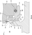
FIG. 2B is a schematic illustration of a portion of a seal member in accordance with an embodiment of the present disclosure; and -
FIG. 2C is a schematic illustration of a portion of a rotating mating ring in accordance with an embodiment of the present disclosure. - Referring to
FIG. 1 , a schematic illustration of amachine 100 having a rotating portion and a stationary portion is shown. Themachine 100 may be an illustrative portion of an electric motor, a generator, a constant speed drive, a gear system, a turbine, a compressor, a pump, an integrated drive generator, or other mechanical system that includes arotating shaft 102 that is arranged relative to and passing into ahousing 104. As shown, the rotatingshaft 102 extends from anexterior space 106 into aninterior space 108, with theinterior space 108 being defined by thehousing 104. The rotatingshaft 102 may have a workingend 110 that is configured to receive an input from another system or may be configured to provide an output from themachine 100. For example, the workingend 110 rotatingshaft 102 may be coupled to a drive shaft, an input shaft, or the like for receiving rotational input from the respective drive shaft, an input shaft, etc. The rotatingshaft 102 in such configurations may be rotor shaft or the like which may rotate magnets or the like, in a configuration of an electric motor or generator. In compressor, pump, turbine, and other similar configurations, the input may be for driving operation to compress, expand, pump or the like. In other configurations, therotating shaft 102 may be driven by components of the machine 100 (e.g., electromagnetic assembly or the like) that drives rotation of the rotatingshaft 102 and work may be extracted from the rotating shaft at the workingend 110. The rotatingshaft 102 may be rotatable about a rotation axis Ax that is defined through a centerline or axis of rotation of the rotatingshaft 102. - As noted, the
housing 104 may define theinterior space 108 and separate theinterior space 108 from theexterior space 106. Theinterior space 108 may be configured to contain a working fluid, such as a lubricating and/or cooling fluid. Examples of such fluids may be oils, synthetic fluids, air-oil mixture, or the like that provide one or both of lubricating and cooling properties. Because the rotatingshaft 102 rotates relative to thestationary housing 104, aseal assembly 112 is provided to prevent the working fluid that is contained within theinterior space 108 from leaking to theexterior space 106. Theseal assembly 112 includes asealing member 114 that is positioned and configured to provide a sealing engagement between thehousing 104 and the rotatingshaft 102. In this configuration, the sealingmember 114 is supported on asupport body 116 that is fixedly attached to thehousing 104 by one ormore fasteners 118. In other configurations, thesupport body 116 may be a part of and/or integrally formed with thehousing 104 and thus may not be separately attached thereto. - The
rotating shaft 102 includes arotating mating ring 120 that extends radially outward from an outer surface of therotating shaft 102. A sealinginterface 122 is defined between contact surfaces of therotating mating ring 120 and the sealingmember 114. Therotating mating ring 120, in this illustrative embodiment and configuration, is a unitary part of therotating shaft 102. However, in other embodiments, therotating mating ring 120 may be a separate structure that is attached to therotating shaft 102, such as by fasteners, adhesives, bonding, welding, or other mechanical and/or chemical connection. - The sealing
member 114 may be biased into contact with therotating mating ring 120 of therotating shaft 102 by a biasingmember 124. In this configuration, the biasingmember 124 is arranged between the sealingmember 114 and thesupport body 116. Theseal assembly 112 includes one or more additional ring seals 126, 128 or gaskets or the like, that provide a seal between components of theseal assembly 112 and/or thehousing 104. As shown, a retainingring 130 may be provided to secure the sealingmember 114 to thesupport body 116 during installation. Further, in some configurations, the retainingring 130 may be provided to limit an axial movement or displacement of the sealingmember 114 to ensure that the sealingmember 114 does not unseat from thesupport body 116. - Even with such a configuration, the working fluid in the
interior space 108 may leak through the sealinginterface 122. The sealinginterface 122 is a face-seal with the sealingmember 114 being a stationary component that is spring-loaded into contact with a face of therotating mating ring 120 of therotating shaft 102. This type of seal may be subject to leakage for a variety of reasons, including but not limited to, geometric or manufacturing imperfections, misalignment during installation and/or operation, or due to wear that is accrued during use and over time. Accordingly, it may be useful to have seal assembly that provides sealing even when the above leakage sources may be present. - That is, in operation, the
seal assembly 112 consists of a stationary member (sealing member 114) that has a flat contacting face at the sealinginterface 112. The rotating mating ring 120 (a portion of the rotating shaft 102) has a flat face that the flat contacting face of the stationary member (sealing member 114) contacts. The stationary member (sealing member 114) is spring loaded against therotating mating ring 120 to provide a seal. However, because there is a higher pressure within the interior space 108 (e.g., generator, gearbox, motor, pump, etc.), such as due to the inclusion of a working fluid (e.g., oil/air mixture) can force oil through the sealinginterface 122 between the sealingmember 114 and therotating mating ring 120. - In view of this and other considerations, embodiments of the present disclosure are directed to a seal assembly that is configured with two adjacent face-seal lands (e.g., sealing face of the sealing member 114) that are spring-loaded into contact with a rotating seal face (e.g., a face of the
rotating mating ring 120 of the rotating shaft 102). - Referring now to
FIGS. 2A-2C , schematic illustrations of amachine 200 having a rotating portion and a stationary portion is shown. Themachine 200 may be an illustrative portion of an electric motor, a generator, a constant speed drive, a gear system, a turbine, a compressor, a pump, an integrated drive generator, or other mechanical system that includes arotating shaft 202 that is arranged relative to and passing into ahousing 204. As shown, therotating shaft 202 extends from anexterior space 206 into aninterior space 208, with theinterior space 208 being defined by thehousing 204. Therotating shaft 202 may have a working end and be rotatable about a rotation axis as shown and described with respect toFIG. 1 . - Similar to that discussed above, the
interior space 208 may be configured to contain a working fluid, such as a lubricating and/or cooling fluid. Because therotating shaft 202 rotates relative to thestationary housing 204, aseal assembly 210 is provided to prevent the working fluid that is contained within theinterior space 208 from leaking to theexterior space 206. Theseal assembly 210 includes a sealingmember 212 that is positioned and configured to provide a sealing engagement between thehousing 204 and therotating shaft 204. In this configuration, the sealingmember 212 is supported on thehousing 204, although in some embodiments, an intermediate support body may be employed, similar to that shown and described above with respect toFIG. 1 . - The
rotating shaft 204 includes arotating mating ring 214 that extends radially outward from an outer surface of therotating shaft 202. A sealinginterface 216 is defined between contact surfaces of therotating mating ring 214 and the sealingmember 212. Therotating mating ring 214, in this illustrative embodiment and configuration, is a unitary part of therotating shaft 202. However, in other embodiments, therotating mating ring 214 may be a separate structure that is attached to therotating shaft 202, such as by fasteners, adhesives, bonding, welding, or other mechanical and/or chemical connection. - The sealing
member 212 may be biased into contact with therotating mating ring 214 at the sealinginterface 216 by a biasingmember 218. In this configuration, the biasingmember 218 is arranged between the sealingmember 212 and a surface of thehousing 204. Theseal assembly 210 includes one or more additional ring seals 220 or gaskets or the like, that provide a seal between components of theseal assembly 210 and/or thehousing 204. As shown, a retainingring 222 may be provided to secure the sealingmember 212 to thehousing 204 during installation. Further, in some configurations, the retainingring 222 may be provided to limit an axial movement or displacement of the sealingmember 212 to ensure that the sealingmember 212 does not unseat from thehousing 204. - In the configuration of
FIGS. 2A-2C , theseal assembly 210, in accordance with this embodiment of the present disclosure, is arranged to define at least two contact points between the sealingmember 212 and therotating mating ring 214. For example, as shown, the sealingmember 212 includes an outerdiameter sealing face 224 and an innerdiameter sealing face 226. Anannular channel 228 is defined between the outerdiameter sealing face 224 and the innerdiameter sealing face 226. As shown inFIG. 2B , theannular channel 228 is a full circumference channel that is defined between the outerdiameter sealing face 224 and the innerdiameter sealing face 226. As such, the sealingmember 212 provides two sealing faces when sealingly engaged to therotating mating ring 214, with the sealing faces arranged radially outward from and radially inward from theannular channel 228, respectively. It will be appreciated that the outerdiameter sealing face 224 and the innerdiameter sealing face 226 collectively define a sealing face of the sealingmember 212. - The
seal assembly 210 further includes a feature formed on therotating mating ring 214. For example, as shown inFIGS. 2A ,2C , therotating mating ring 214 includes one or more ejection holes 230. The ejection holes 230 may be holes, channels, passageways, openings, or the like. In some embodiments, the cross-sectional area of the ejection holes 230 may be substantially uniform, and in other embodiments, the cross-sectional area of the ejection holes 230 may be tapered (either inward or outward), depending on the specific configuration. The specific illustrative geometry of the ejection holes 230 is not intended to be limiting. The ejection holes 230 are angled channels or open fluid paths that extend at a radially inward position that aligns with theannular channel 228 and formed on arotating sealing face 229 and then extends radially outward therefrom and axially away from theannular channel 228 through therotating mating ring 214. As such, the ejection holes 230 extend from a radially inward position on therotating sealing face 229 at a first axial position and extend axially and radially outward therefrom to a radially outward position. The radially inward position of the ejection holes 230 is open to theannular channel 228 and thus may define an inlet end of the ejection holes 230 formed in therotating sealing face 229. and the radially outward end of the ejection holes 230 may be referred to as an outlet end of the ejection holes 230. Therotating mating ring 214 may be formed with an equal distribution of ejection holes 230 that are equally distributed about a circumference of therotating mating ring 214. The sealinginterface 216 is defined between surfaces of therotating sealing face 229 and the faces of the outerdiameter sealing face 224 and the innerdiameter sealing face 226. - As shown in
FIG. 2A , a workingfluid 232 may attempt to flow along the sealinginterface 216. The workingfluid 232 may be a high pressure fluid having a higher pressure than a pressure of theexterior space 206. As such, the pressure differential between theinterior space 208 having the workingfluid 232 may tend cause the workingfluid 232 to try to reach theexterior space 206. However, if the workingfluid 232 successfully passes by the sealinginterface 216 between the outerdiameter sealing face 224 and therotating sealing face 229, the working fluid will enter theannular channel 228 which is defined between the outerdiameter sealing face 224 and the innerdiameter sealing face 226 in a radial direction, and between a recessed surface of theannular channel 228 of the sealingmember 212 and a sealing face of therotating mating ring 214. When the workingfluid 232 enters theannular channel 228, because therotating shaft 202 is rotating, a centrifugal force will operate as a pumping action to remove the working fluid from theannular channel 228 of the sealingmember 212 radially outward along and through the ejection holes 230, and will not pass through the sealinginterface 216 between the innerdiameter sealing face 226 and therotating sealing face 229 of therotating mating ring 214. - In operation, the sealing
member 212 is a stationary component that has two lands (e.g., the outerdiameter sealing face 224 and the inner diameter sealing face 226). The sealingmember 212 is spring loaded against the rotating sealingface 229 of therotating mating ring 214 by the biasingmember 218. The biasingmember 218 may be a coil spring, wave spring, biased-piston assembly, linear spring, or the like. Working fluid (e.g., oil, air, mixture of oil and air, other fluids, etc.) from theinterior space 208 within thehousing 204 may leak past the outerdiameter sealing face 224 into the small cavity that defines theannular channel 228 between the outerdiameter sealing face 224 and the innerdiameter sealing face 226. A number of the ejection holes 230 are formed in and through therotating mating ring 214 to provide a path through which the working fluid within theannular channel 228 may be ejected back into theinterior space 208. That is, due to the rotation of therotating mating ring 214, centrifugal force pumping action removes the working fluid from theannular channel 228, thereby preventing leakage of the working fluid past the innerdiameter sealing face 226 to theexterior space 206. - Advantageously, embodiments described herein provide improved sealing between a rotating component and a stationary component. For example, in accordance with embodiments of the present disclosure, a stationary sealing member is provided with two sealing faces with an annular channel defined between the two sealing faces. When the two sealing faces of the stationary sealing member are arranged in contact with a sealing face of a rotating mating ring, an annular cavity is defined between the structure and surfaces of the stationary sealing member and the rotating mating ring. The rotating mating ring includes one or more ejection holes that extend radially outward from an inlet end that aligns with the annular cavity to an outlet having a position that is radially outboard from the inlet of the ejection hole. This radial change from inlet to outlet of the ejection hole in combination with the rotation of the rotating mating ring results in an centrifugal pump that pumps fluid from within the annular cavity along the ejection holes. Because the outlet end of the ejection holes is oriented and facing an interior space of the machine, the working fluid is reintroduced into the interior space rather than passing through the sealing interface and exiting the interior space and entering the exterior space as leakage. Accordingly, advantageously, embodiments of the present disclosure are directed to improved seal assemblies for sealing between a rotating component and a non-rotating component.
- The use of the terms "a", "an", "the", and similar references in the context of description (especially in the context of the following claims) are to be construed to cover both the singular and the plural, unless otherwise indicated herein or specifically contradicted by context. The modifier "about" used in connection with a quantity is inclusive of the stated value and has the meaning dictated by the context (e.g., it includes the degree of error associated with measurement of the particular quantity). All ranges disclosed herein are inclusive of the endpoints, and the endpoints are independently combinable with each other. As used herein, the terms "about" and "substantially" are intended to include the degree of error associated with measurement of the particular quantity based upon the equipment available at the time of filing the application. For example, the terms may include a range of ± 8%, or 5%, or 2% of a given value or other percentage change as will be appreciated by those of skill in the art for the particular measurement and/or dimensions referred to herein. It should be appreciated that relative positional terms such as "forward," "aft," "upper," "lower," "above," "below," and the like are with reference to normal operational attitude and should not be considered otherwise limiting.
- While the present disclosure has been described in detail in connection with only a limited number of embodiments, it should be readily understood that the present disclosure is not limited to such disclosed embodiments. Rather, the present disclosure can be modified to incorporate any number of variations, alterations, substitutions, combinations, sub-combinations, or equivalent arrangements not heretofore described, but which are commensurate with the scope of the present disclosure. Additionally, while various embodiments of the present disclosure have been described, it is to be understood that aspects of the present disclosure may include only some of the described embodiments.
- Accordingly, the present disclosure is not to be seen as limited by the foregoing description, but is only limited by the scope of the appended claims.
Claims (15)
- A seal assembly for sealing between a stationary component and a rotating component, the seal assembly comprising:a sealing member (114) having a sealing face comprising an outer diameter sealing face (224) and an inner diameter sealing face (226), wherein an annular channel is defined in the sealing face between the outer diameter sealing face (224) and an inner diameter sealing face (226) and wherein the sealing member (114) is attached to the stationary component; anda rotating mating ring (214) attached to the rotating component, the rotating mating ring (214) having a rotating sealing face (229), wherein the rotating mating ring (214) comprises at least one ejection hole (230) extending through the rotating mating ring (214) from the rotating sealing face (229) at an inlet end and a radially outward outlet end.
- The seal assembly of claim 1, wherein the rotating mating ring (214) comprises a plurality of ejection holes (230) distributed equally about a circumference of the rotating mating ring (214).
- The seal assembly of claim 1, wherein the sealing member (114) is attached to a housing (204) of the stationary component.
- The seal assembly of claim 3, wherein the sealing member (114) is biased against the housing (204) and into engagement with the rotating mating ring (214).
- The seal assembly of claim 3, further comprising at least one ring seal (220) sealingly engaged between a surface of the sealing member (114) and a surface of the housing (204).
- The seal assembly of claim 3, further comprising a retaining ring (222) configured to axially secure the sealing member (114) to the housing (204).
- The seal assembly of claim 1, wherein the sealing member (114) is attached to a support body (116), the support body (116) being attached to a housing (204) of the stationary component.
- The seal assembly of claim 7, wherein the sealing member (114) is biased against the support body (116) and into engagement with the rotating mating ring (214).
- The seal assembly of claim 7, further comprising at least one ring seal (220) sealingly engaged between a surface of the sealing member (114) and a surface of the support body (116).
- The seal assembly of claim 7, further comprising a retaining ring (222) configured to axially secure the sealing member (114) to the support body (116).
- The seal assembly of any preceding claim, wherein the rotating mating ring (214) is integrally formed with the rotating component.
- The seal assembly of any preceding claim, wherein the stationary component is a housing (204) of a machine and the rotating component is a rotating shaft of the machine.
- The seal assembly of claim 12, wherein the machine is an electric motor; and/or wherein the machine is a pump; and/or wherein the machine is a gearbox; and/or wherein the machine is a turbine; and/or wherein the machine is a compressor; and/or wherein the machine is one of a generator, a constant speed drive, and an integrated drive generator.
- A machine comprising:a stationary component;a rotating component arranged to rotate relative to the stationary component; anda seal assembly, as claimed in claim 1, for sealing between the stationary component and the rotating component.
- The machine of claim 14, wherein the sealing member (114) is attached to a housing (204) of the stationary component.
Applications Claiming Priority (1)
| Application Number | Priority Date | Filing Date | Title |
|---|---|---|---|
| US18/164,218 US12117083B2 (en) | 2023-02-03 | 2023-02-03 | Sealing assemblies for sealing between rotating and non-rotating components |
Publications (1)
| Publication Number | Publication Date |
|---|---|
| EP4411180A1 true EP4411180A1 (en) | 2024-08-07 |
Family
ID=89620784
Family Applications (1)
| Application Number | Title | Priority Date | Filing Date |
|---|---|---|---|
| EP24152409.9A Pending EP4411180A1 (en) | 2023-02-03 | 2024-01-17 | Sealing assemblies for sealing between rotating and nonrotating components |
Country Status (2)
| Country | Link |
|---|---|
| US (1) | US12117083B2 (en) |
| EP (1) | EP4411180A1 (en) |
Citations (3)
| Publication number | Priority date | Publication date | Assignee | Title |
|---|---|---|---|---|
| US3147013A (en) * | 1961-02-10 | 1964-09-01 | Borg Warner | Dry gas seal |
| US3941394A (en) * | 1974-12-09 | 1976-03-02 | Crane Packing Company | No-leak double rotary mechanical seal |
| EP1079156A1 (en) * | 1999-08-16 | 2001-02-28 | Nippon Pillar Packing Co., Ltd. | Non-contact type mechanical seal |
Family Cites Families (5)
| Publication number | Priority date | Publication date | Assignee | Title |
|---|---|---|---|---|
| US4406459A (en) | 1982-06-18 | 1983-09-27 | United Technologies Corporation | Oil weepage return for carbon seal plates |
| US5174584A (en) | 1991-07-15 | 1992-12-29 | General Electric Company | Fluid bearing face seal for gas turbine engines |
| US6131912A (en) * | 1997-12-17 | 2000-10-17 | A.W. Chesterton Company | Split mechanical face seal |
| US7780399B1 (en) | 2006-01-12 | 2010-08-24 | Stein Seal Company | Reverse pressure double dam face seal |
| DE102020203767B4 (en) * | 2020-03-24 | 2022-05-05 | Eagleburgmann Germany Gmbh & Co. Kg | Self-priming mechanical seal assembly |
-
2023
- 2023-02-03 US US18/164,218 patent/US12117083B2/en active Active
-
2024
- 2024-01-17 EP EP24152409.9A patent/EP4411180A1/en active Pending
Patent Citations (3)
| Publication number | Priority date | Publication date | Assignee | Title |
|---|---|---|---|---|
| US3147013A (en) * | 1961-02-10 | 1964-09-01 | Borg Warner | Dry gas seal |
| US3941394A (en) * | 1974-12-09 | 1976-03-02 | Crane Packing Company | No-leak double rotary mechanical seal |
| EP1079156A1 (en) * | 1999-08-16 | 2001-02-28 | Nippon Pillar Packing Co., Ltd. | Non-contact type mechanical seal |
Also Published As
| Publication number | Publication date |
|---|---|
| US12117083B2 (en) | 2024-10-15 |
| US20240263705A1 (en) | 2024-08-08 |
Similar Documents
| Publication | Publication Date | Title |
|---|---|---|
| CA2809985C (en) | Deoiler seal | |
| EP2520835B1 (en) | Hydrodynamic non-contacting seal | |
| US4406460A (en) | Anti-weepage valve for rotating seals | |
| US7055827B2 (en) | Non-contacting clearance seal for high misalignment applications | |
| US4406459A (en) | Oil weepage return for carbon seal plates | |
| US6679678B2 (en) | Increased wear-life mechanical face seal anti-rotation system | |
| CN119084582A (en) | Non-contact labyrinth seals made with additive manufacturing | |
| EP4449008B1 (en) | Grease inhibitor | |
| CN110056430B (en) | Bearing common-cavity lubricating and shaft-to-shaft sealing device and birotor aero-engine | |
| SE525515C2 (en) | Shaft sealing assembly for dynamic and static axial sealing of rotary shaft has static seal which is arranged in recess of rotor and axially and radially moves from static sealing position to dynamic sealing position upon rotation of shaft | |
| US9303529B2 (en) | Lube spacer bearing with pressure loading channel | |
| KR102636718B1 (en) | Double drive vane pump | |
| CN212690341U (en) | Oil-free screw compressor sealing structure | |
| US12117083B2 (en) | Sealing assemblies for sealing between rotating and non-rotating components | |
| RU2632066C2 (en) | Device to provide seal between coaxial shafts of turbomachine | |
| CN110925079B (en) | Turbocharger and matching ring contained therein | |
| WO2002016740A1 (en) | Labyrinth helical seal | |
| US11692466B2 (en) | Machine having a liquid lubrication system and a shaft | |
| JP5499400B2 (en) | Fuel / lubricating oil supply pump | |
| US5417555A (en) | Rotary vane machine having end seal plates | |
| EP4442965A1 (en) | Rotating seal with oil slinger | |
| JP2021046805A (en) | Scroll type fluid machine | |
| JP7862580B2 (en) | Centrifugal oil pump device for vacuum pumps | |
| CN218564214U (en) | High-speed transmission bearing device | |
| EP1637782A1 (en) | Seal housing for a mechanical seal |
Legal Events
| Date | Code | Title | Description |
|---|---|---|---|
| PUAI | Public reference made under article 153(3) epc to a published international application that has entered the european phase |
Free format text: ORIGINAL CODE: 0009012 |
|
| STAA | Information on the status of an ep patent application or granted ep patent |
Free format text: STATUS: THE APPLICATION HAS BEEN PUBLISHED |
|
| AK | Designated contracting states |
Kind code of ref document: A1 Designated state(s): AL AT BE BG CH CY CZ DE DK EE ES FI FR GB GR HR HU IE IS IT LI LT LU LV MC ME MK MT NL NO PL PT RO RS SE SI SK SM TR |
|
| STAA | Information on the status of an ep patent application or granted ep patent |
Free format text: STATUS: REQUEST FOR EXAMINATION WAS MADE |
|
| 17P | Request for examination filed |
Effective date: 20250205 |