EP4411171A1 - Double clutch architecture transmission for agricultural vehicles - Google Patents
Double clutch architecture transmission for agricultural vehicles Download PDFInfo
- Publication number
- EP4411171A1 EP4411171A1 EP24156112.5A EP24156112A EP4411171A1 EP 4411171 A1 EP4411171 A1 EP 4411171A1 EP 24156112 A EP24156112 A EP 24156112A EP 4411171 A1 EP4411171 A1 EP 4411171A1
- Authority
- EP
- European Patent Office
- Prior art keywords
- gear
- stage
- shaft
- clutch
- range
- Prior art date
- Legal status (The legal status is an assumption and is not a legal conclusion. Google has not performed a legal analysis and makes no representation as to the accuracy of the status listed.)
- Pending
Links
Images


Classifications
-
- F—MECHANICAL ENGINEERING; LIGHTING; HEATING; WEAPONS; BLASTING
- F16—ENGINEERING ELEMENTS AND UNITS; GENERAL MEASURES FOR PRODUCING AND MAINTAINING EFFECTIVE FUNCTIONING OF MACHINES OR INSTALLATIONS; THERMAL INSULATION IN GENERAL
- F16H—GEARING
- F16H3/00—Toothed gearings for conveying rotary motion with variable gear ratio or for reversing rotary motion
- F16H3/02—Toothed gearings for conveying rotary motion with variable gear ratio or for reversing rotary motion without gears having orbital motion
- F16H3/08—Toothed gearings for conveying rotary motion with variable gear ratio or for reversing rotary motion without gears having orbital motion exclusively or essentially with continuously meshing gears, that can be disengaged from their shafts
- F16H3/087—Toothed gearings for conveying rotary motion with variable gear ratio or for reversing rotary motion without gears having orbital motion exclusively or essentially with continuously meshing gears, that can be disengaged from their shafts characterised by the disposition of the gears
- F16H3/093—Toothed gearings for conveying rotary motion with variable gear ratio or for reversing rotary motion without gears having orbital motion exclusively or essentially with continuously meshing gears, that can be disengaged from their shafts characterised by the disposition of the gears with two or more countershafts
-
- F—MECHANICAL ENGINEERING; LIGHTING; HEATING; WEAPONS; BLASTING
- F16—ENGINEERING ELEMENTS AND UNITS; GENERAL MEASURES FOR PRODUCING AND MAINTAINING EFFECTIVE FUNCTIONING OF MACHINES OR INSTALLATIONS; THERMAL INSULATION IN GENERAL
- F16H—GEARING
- F16H37/00—Combinations of mechanical gearings, not provided for in groups F16H1/00 - F16H35/00
- F16H37/02—Combinations of mechanical gearings, not provided for in groups F16H1/00 - F16H35/00 comprising essentially only toothed or friction gearings
- F16H37/04—Combinations of toothed gearings only
- F16H37/042—Combinations of toothed gearings only change gear transmissions in group arrangement
- F16H37/043—Combinations of toothed gearings only change gear transmissions in group arrangement without gears having orbital motion
-
- F—MECHANICAL ENGINEERING; LIGHTING; HEATING; WEAPONS; BLASTING
- F16—ENGINEERING ELEMENTS AND UNITS; GENERAL MEASURES FOR PRODUCING AND MAINTAINING EFFECTIVE FUNCTIONING OF MACHINES OR INSTALLATIONS; THERMAL INSULATION IN GENERAL
- F16H—GEARING
- F16H37/00—Combinations of mechanical gearings, not provided for in groups F16H1/00 - F16H35/00
- F16H37/02—Combinations of mechanical gearings, not provided for in groups F16H1/00 - F16H35/00 comprising essentially only toothed or friction gearings
- F16H37/04—Combinations of toothed gearings only
- F16H37/042—Combinations of toothed gearings only change gear transmissions in group arrangement
- F16H37/043—Combinations of toothed gearings only change gear transmissions in group arrangement without gears having orbital motion
- F16H2037/044—Combinations of toothed gearings only change gear transmissions in group arrangement without gears having orbital motion comprising a separate gearing unit for shifting between forward or reverse
-
- F—MECHANICAL ENGINEERING; LIGHTING; HEATING; WEAPONS; BLASTING
- F16—ENGINEERING ELEMENTS AND UNITS; GENERAL MEASURES FOR PRODUCING AND MAINTAINING EFFECTIVE FUNCTIONING OF MACHINES OR INSTALLATIONS; THERMAL INSULATION IN GENERAL
- F16H—GEARING
- F16H37/00—Combinations of mechanical gearings, not provided for in groups F16H1/00 - F16H35/00
- F16H37/02—Combinations of mechanical gearings, not provided for in groups F16H1/00 - F16H35/00 comprising essentially only toothed or friction gearings
- F16H37/04—Combinations of toothed gearings only
- F16H37/042—Combinations of toothed gearings only change gear transmissions in group arrangement
- F16H37/043—Combinations of toothed gearings only change gear transmissions in group arrangement without gears having orbital motion
- F16H2037/045—Combinations of toothed gearings only change gear transmissions in group arrangement without gears having orbital motion comprising a separate gearing unit for shifting between high and low ratio range
-
- F—MECHANICAL ENGINEERING; LIGHTING; HEATING; WEAPONS; BLASTING
- F16—ENGINEERING ELEMENTS AND UNITS; GENERAL MEASURES FOR PRODUCING AND MAINTAINING EFFECTIVE FUNCTIONING OF MACHINES OR INSTALLATIONS; THERMAL INSULATION IN GENERAL
- F16H—GEARING
- F16H2200/00—Transmissions for multiple ratios
- F16H2200/003—Transmissions for multiple ratios characterised by the number of forward speeds
- F16H2200/0078—Transmissions for multiple ratios characterised by the number of forward speeds the gear ratio comprising twelve or more forward speeds
Definitions
- the present invention relates to a dual clutch transmission architecture, in particular a dual clutch transmission architecture for an off road vehicle such as an agricultural vehicle and to a related method for controlling the gear shifting of such dual clutch transmission.
- Transmissions for off road vehicles such as agricultural vehicles offer different configuration, for instance:
- DCT dual-clutch transmission
- DCT architecture has been applied in the field of the transmissions for agricultural vehicles.
- An example of such DCT architecture is disclosed in patent document WO2019091953 A1 .
- Aim of the present invention is to satisfy the above mentioned needs in a cost-effective and optimized way.
- Figure 1 discloses a dual clutch transmission 1, in the following "transmission”, for an off road vehicle, such as an agricultural vehicle, e.g. a tractor (not illustrated), comprising an engine input shaft 2, operatively connected to a torque source (not shown), such as an internal combustion engine of the work vehicle, and an output shaft 3, which can be coupled to a drive axle of the off road vehicle.
- an off road vehicle such as an agricultural vehicle, e.g. a tractor (not illustrated)
- a torque source such as an internal combustion engine of the work vehicle
- an output shaft 3 which can be coupled to a drive axle of the off road vehicle.
- the transmission 1 essentially comprises, operatively connected in series one to the other between input shaft 2 and output shaft 3, an input stage A, a gear ratio stage B and a range gear ratio stage C.
- the input stage A may be realized in different manner to provide torque to a first main clutch 5, hereinafter “forward clutch”, and torque in reversed direction to a second main clutch 6, hereinafter “rearward clutch”, both carried by the engine input shaft 2.
- input stage A comprises a gearing 4 comprising a first wheel 4a fixedly carried by the engine shaft 2 and configured to mesh with a second wheel 4b rotatably fixed to a support shaft 10 carrying the rearward clutch 6.
- first and the second wheels 4a, 4b may mesh via a counterwheel arrangement 4c, e.g. comprising two idler wheels as shown.
- the forward clutch 5 couples the engine input shaft 2 to the output shaft 3 in order to allow a forward motion of the work vehicle while the rearward clutch 6 couples the engine input shaft 2 to the output shaft 3 in order to allow a rearward motion of the work vehicle.
- such occurrence is given by the peculiar construction of gearing 4 as described above.
- Transmission 1 further comprise a first clutch 7, hereinafter “even clutch”, and a second clutch 8, hereinafter “odd clutch”.
- the even clutch 7 is configured to couple a first auxiliary shaft 11, hereinafter “even shaft”, with the forward clutch 5.
- the odd clutch 8 is configured to couple a second auxiliary shaft 12, hereinafter “odd shaft”, with the rearward clutch 6.
- the forward clutch 5 and the rearward clutch 6 are coupled to the even and odd clutches 7, 8 by a gearing 9.
- the gearing 9 comprises first wheels 9a, 9a' carried free in rotation to engine shaft 2 and the support shaft 10 respectively and a pair of second wheels 9b, 9b' respectively carried fixedly at rotation by even and odd clutch housings.
- first wheel 9a carried by the engine shaft 2 meshes with the second wheel 9b engaged with even clutch 7 and this latter meshes with the first wheel 9a' carried by support shaft 10 that further meshes with the second wheel 9b' engaged with odd clutch 8.
- the even and odd shafts 11, 12 may be coupled to the rearward clutch 6 or the rearward clutch 5 via different gear ratios.
- the even and the odd clutches 8, 9 are axially offset with respect to forward and rearward clutches 5, 6.
- One of this latter is at least partially comprised between the even and the odd clutches 8, 9 along a transversal direction with respect to axial direction of the transmission, i.e. the direction of the axis of engine shaft 2.
- forward and rearward clutches 5, 6 are placed on the same side of even and odd clutches with respect to gearing 9.
- the even shaft 11 and the odd shaft 12 each comprises a plurality of selection elements 17 e.g. synchronizer or dug clutches, fixedly carried by the respective shaft 11, 12 and therefore rotate together with to these latter.
- selection elements 17 may comprise other equivalent connection means such as joint clutches.
- the gear ratio stage B comprises a plurality of gears 14, 15 accommodated on respectively even or odd shafts 11, 12 and having a different size one with respect to the other and that are supported in a rotatable free manner the respective shaft 11, 12, e.g. by means of bearings, so that they are not forced to rotate to the same speed of the respective shaft 11, 12 when the engaging dog clutch 17 is in their neutral position.
- the even shaft 11 may comprise four gears 14, namely a first gear 14 I having the biggest diameter, a fourth gear 14 IV having the smallest diameter and a second and third gears 14 II , 14 III having respective diameters comprised between the ones of first and the fourth gears 14 I , 14 IV .
- the odd shaft 12 may comprise four gears 15, namely a first gear 15 I having the biggest diameter, a fourth gear 15 IV having the smallest diameter and a second and third gears 15 II , 15 III having respective diameters comprised between the ones of first and the fourth gears 15 I , 15 IV .
- gear 14 I has the same diameter of gear 15 I
- gear 14 II has the same diameter of gear 15 II
- gear 14 III has the same diameter of gear 15 III
- gear 14 IV has the same diameter of gear 15 IV .
- the gears of gears sets 14, 15, when selected, represent the different speed ratios of the transmission, namely a first, a second, a third, a fourth, a fifth, a sixth, a seventh and a eight speed ratio according to the specific selection of one of the aforementioned wheels 14, 15.
- gears of the gears sets 14, 15 may be selected by a dog clutch 17 configured to couple the shaft with the chosen gear.
- the even shaft 11 may comprise two dog clutches 17 interposed respectively between the gear 14 I - 14 II and 14 III -14 IV .
- the odd shaft 12 may comprise two dog clutches 17 interposed respectively between the gear 15 I - 15 II and 15 III -15 IV .
- the transmission 1 further comprises an intermediate shaft 20 configured to engage with gear wheels 14, 15 and with gear range stage C.
- the intermediate shaft 20 is configured to carry a number of wheels 21 corresponding to the wheels of the gear ratio stage B.
- wheels are carried in a rigid manner to rotation by intermediate shaft 20.
- intermediate shaft 20 carries a first wheel 21 I , a second wheel 21 II , a third wheel 21 III and a fourth wheel 21 IV .
- the gear range stage C is configured to engage a number of the wheels 21 carried by intermediate shaft 20 to the output shaft 3 by choosing among a plurality of gear ratios, defined by respective range gears 22, which are multiplied by the gear ratio of gear ratio stage B.
- the gear range stage G comprises a first range gear 22 I called “low” range, a second range gear 22 II “medium-low” range, and a third range gear 22 III called “ medium-fast” range and a fourth range gear 22 IV called “fast” range ; the four range gears have different dimensions.
- the transmission provides thirty two possible gear ratios, due to the eight gear ratios repeated over the four range gear ratios.
- the medium low and fast gears 22 II ,22 III meshes with corresponding wheels 21 of the intermediate shaft 20, in particular, with the third and fourth wheels 21 III , 21 IV of the intermediate shaft 20.
- the gear ratio wheels 22 are all carried in a rotatably free manner on a support shaft 23 and selectively engageable in rotation to this latter thanks to selection means 17 as the ones mentioned above.
- range wheels 22, in particular medium-low and fast gears 22 II , 22 IV are rotatable free carried by an auxiliary shaft 24 that is rotatably carried over the support shaft 23.
- Such auxiliary shaft 24 is selectively connectable to the output shaft 3 via clutch means 25 realized between the output shaft 3 and support shaft 23.
- the support shaft 23 is selectively connectable to the auxiliary shaft 24 thanks to clutch means 26 realized between the auxiliary shaft 24 and support shaft 23.
- the range wheels 22 are two by two connected together.
- the low range gear 22 I is connected to the medium fast range gear 22 III and the medium low range gear 22 II is connected to the fast range gear 22 IV .
- the medium low gear 22 III is connected to the fast range gear 22 IV via a gearing 30 comprising a pair of wheels 30', 30'' respectively meshing with the medium low gear 22 III and the fast range gear 22 IV and configured to be fixed at rotation one with respect to the other.
- the medium fast gear 22 II is connected to the low range gear 22 I via a gearing 31 comprising a pair of wheels 31', 31'' respectively meshing with the medium fast gear 22 II and the low range gear 22 I and configured to be fixed at rotation one with respect to the other.
- gearings 30 and 31 are carried by a common shaft 32 that carries the wheels of the aforementioned gearings 30, 31 in a free manner with respect to rotation.
- clutch means 25, 26 are preferably realized with a housing in common, i.e. they are concentric along axial direction of the transmission, i.e. along the axis of support shaft 23.
- the aforementioned housing is fixed at rotation to output shaft 3.
- the above described clutches 5, 6, 7, 8, 25, 26 selection elements 17 can be selected by respective actuators (not shown) that are controlled by an electronic control unit (not shown).
- the electronic control unit controls said clutches or said electronic motors by sending control electric signals directed to the respective clutches or motors to be controlled.
- Electronic control unit can be either the ECU of the vehicle or driveline ECU of the vehicle.
- the electronic unit is configured to control the above cited elements of the transmission 1 as per direct input command of the user of the vehicle or in automatic way following the shift control logic deployed into a specific software code, which can be memorized into the electronic unit.
- FIG. 1A In a first example of operation, shown in figure 1A , it is represented a standard operation in "first slow".
- the torque provided by input stage A passes through forward clutch 5, odd clutch 8 to odd shaft 12.
- First gear wheel 15 I is engaged via selection elements 17 and therefore transmits torque to the first wheel 21 I.
- torque passes to support shaft 23 that is connected via clutch 28 to output shaft 3, then the torque flows to output shaft 3.
- Shift between speed ratios is managed by properly controlling selection means 17 and clutches 5, 6, 7, 8, 28, 29 thereby providing a powershift transmission along the thirty two speed ratio, as detailed by the combination of engagement of figure 2 .
- the vehicle may be provided by a dedicated control software code in the ECU of the transmission configured to recognize signals from sensors installed on the vehicle, e.g. the torque demand at the output shaft 3 and the speed of the engine input shaft 2, and automatically define the gearshift without any user intervention.
- the invention also relates to a method for operating a transmission 1 as described above for shifting from a gear 14, 15 of a gear ratio stage B in combination a gear 22 of range gear stage C to a further gear 14, 15 of the gear ratio stage B in combination the same gear 22 of range gear stage C:
- the invention also relates to a method for operating a transmission 1 as described above for shifting from a gear 14, 15 of a gear ratio stage B in combination a gear 22, 35 of range gear stage C to a further gear 14, 15 of the gear ratio stage B with a further gear 22of range gear stage C:
- the transmission architecture 1 according to the invention increases the efficiency of the system.
- the proposed arrangement provides a better and facilitated mounting, thereby allowing a cheaper and quicker manufacture of the transmission architecture.
- the range gear wheels may be designed smaller since the inertia carried by the range gear wheel is smaller with respect to known transmission architecture. Indeed the torque is split into different paths thanks to the specific arrangement of wheels on the intermediate shaft 20 and of the range wheels on the support shaft 23.
- gears of gear ratio, range and idler gears may be varied according to vehicle necessity.
- transmission may comprise different elements with respect to the described one, e.g. the number and/or typologies of clutches, gears and clutches may be varied. Accordingly, input stage A may be realized in any convenient manner.
- control and typology of selection means 17 may be implemented with any typology of control, e.g. a hydraulic, electric or pneumatic in alternative or in combinations.
Landscapes
- Engineering & Computer Science (AREA)
- General Engineering & Computer Science (AREA)
- Mechanical Engineering (AREA)
- Structure Of Transmissions (AREA)
Abstract
the transmission (1) comprises selection elements (17) configured to selectively couple gears (14, 15,22) of gear ratio stage (B) and range gear ratio stage (C) to the respective first and second shafts (11, 12) and support shaft (23).
Description
- The present invention relates to a dual clutch transmission architecture, in particular a dual clutch transmission architecture for an off road vehicle such as an agricultural vehicle and to a related method for controlling the gear shifting of such dual clutch transmission.
- Transmissions for off road vehicles such as agricultural vehicles offer different configuration, for instance:
- manual shifted transmissions, in which all gears of the transmissions are engaged directly by the driver through lever mechanisms which command clutches, synchronizers and dog clutches to select the gear;
- semi-powershift transmission, in which some gears are engaged, manually or automatically, thanks to servo actuated mechanisms in powershift mode, i.e. by swapping the torque by a couple of clutches, and in which other gears are actuated by lever mechanisms which commands clutches, synchronizers and dog clutches to select the gear or by a servo-actuated mechanism which is not in powershift mode, i.e. which uses a single clutch and, when such clutch is opened, torque cannot pass through the transmission; and
- full powershift transmission, in which all gears of the transmission are engaged through servo actuated mechanism in powershift mode.
- An important request that must be satisfied in modern mechanical transmission for agricultural vehicles is to have high efficiency across the full ground speed range, in order to improve the vehicle fuel consumption. In this respect a large use of wet clutches to build the semi-powershift or the full-powershift transmissions, generates more power losses inside the transmission when compared to the use of synchronizers and dog-clutches and, as consequence, a penalty of efficiency as consequence.
- For this reason, in the art, the dual-clutch transmission, DCT, architecture is considered the most valuable layout for powershift transmissions in order to satisfy all the previous demands:
- it provides an high number of speed ratios with a mechanism that allow for a comfortable powershift (by swapping one couple of clutches); and
- it performs high efficiency, because a powershift layout is provided by only few couples of wet clutches accompanied by many synchronizers and dog-clutches.
- Because of these advantages, recently DCT architecture has been applied in the field of the transmissions for agricultural vehicles. An example of such DCT architecture is disclosed in patent document
WO2019091953 A1 . - However such known architectures used big wet clutches that dissipate a considerable amount of energy, in particular for allowing shift between range gears.
- Moreover, during shifting between gear ratio or range gear ratio, the inertia of the carried transmission elements is considerable. Therefore resistant torque is high and the fuel consumption is not neglectable during shifting.
- In conclusion, the need is felt to improve existing DCT architecture for agricultural vehicle in order to improve their performances in all its working speed ranges and to improve the comfort during all gears shifting.
- Moreover, it is requested to reduce the overall encumbrance/weight of the transmission architecture and to reduce the time for its manufacturing.
- Aim of the present invention is to satisfy the above mentioned needs in a cost-effective and optimized way.
- The aforementioned aim is reached by an architecture for a dual clutch transmission and a related control method as claimed in the appended set of claims.
- For a better understanding of the present invention, a preferred embodiment is described in the following, by way of a non-limiting example, with reference to the attached drawings wherein:
-
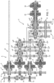
Figure 1 is a schematic representation of a dual clutch transmission architecture according to the invention; -
Figure 1A is a schematic representation of the transmission of the invention with indication of torque path during an exemplarily operation; and -
Figure 2 is a table indicating the activation of elements of the transmission architecture according to the invention. -
Figure 1 discloses adual clutch transmission 1, in the following "transmission", for an off road vehicle, such as an agricultural vehicle, e.g. a tractor (not illustrated), comprising anengine input shaft 2, operatively connected to a torque source (not shown), such as an internal combustion engine of the work vehicle, and anoutput shaft 3, which can be coupled to a drive axle of the off road vehicle. - The
transmission 1 essentially comprises, operatively connected in series one to the other betweeninput shaft 2 andoutput shaft 3, an input stage A, a gear ratio stage B and a range gear ratio stage C. - The input stage A may be realized in different manner to provide torque to a first
main clutch 5, hereinafter "forward clutch", and torque in reversed direction to a secondmain clutch 6, hereinafter "rearward clutch", both carried by theengine input shaft 2. - In disclosed exemplarily embodiment, input stage A comprises a
gearing 4 comprising afirst wheel 4a fixedly carried by theengine shaft 2 and configured to mesh with a second wheel 4b rotatably fixed to asupport shaft 10 carrying therearward clutch 6. In particular, the first and thesecond wheels 4a, 4b may mesh via acounterwheel arrangement 4c, e.g. comprising two idler wheels as shown. - As per se known, the
forward clutch 5 couples theengine input shaft 2 to theoutput shaft 3 in order to allow a forward motion of the work vehicle while therearward clutch 6 couples theengine input shaft 2 to theoutput shaft 3 in order to allow a rearward motion of the work vehicle. In the disclosed exemplarily embodiment, such occurrence is given by the peculiar construction ofgearing 4 as described above. -
Transmission 1 further comprise afirst clutch 7, hereinafter "even clutch", and asecond clutch 8, hereinafter "odd clutch". The evenclutch 7 is configured to couple a firstauxiliary shaft 11, hereinafter "even shaft", with theforward clutch 5. Theodd clutch 8 is configured to couple a secondauxiliary shaft 12, hereinafter "odd shaft", with therearward clutch 6. - Advantageously, the
forward clutch 5 and therearward clutch 6 are coupled to the even andodd clutches gearing 9. Thegearing 9 comprisesfirst wheels engine shaft 2 and thesupport shaft 10 respectively and a pair ofsecond wheels - In particular, the
first wheel 9a carried by theengine shaft 2 meshes with thesecond wheel 9b engaged with evenclutch 7 and this latter meshes with thefirst wheel 9a' carried bysupport shaft 10 that further meshes with thesecond wheel 9b' engaged withodd clutch 8. - In view of above, thanks to the coupling of
wheels odd shafts rearward clutch 6 or therearward clutch 5 via different gear ratios. - It is noticed that the even and the
odd clutches rearward clutches odd clutches engine shaft 2. - Furthermore, it is noticed that even and
odd clutches rearward clutches transmission 1 is reduced. - In particular, it is noticed that forward and rearward
clutches - The
even shaft 11 and theodd shaft 12 each comprises a plurality ofselection elements 17 e.g. synchronizer or dug clutches, fixedly carried by therespective shaft selection elements 17 may comprise other equivalent connection means such as joint clutches. - The gear ratio stage B comprises a plurality of
gears odd shafts respective shaft respective shaft engaging dog clutch 17 is in their neutral position. - Preferably the
even shaft 11 may comprise fourgears 14, namely afirst gear 14I having the biggest diameter, afourth gear 14IV having the smallest diameter and a second andthird gears fourth gears - Similarly, the
odd shaft 12 may comprise fourgears 15, namely afirst gear 15I having the biggest diameter, afourth gear 15IV having the smallest diameter and a second andthird gears fourth gears - Advantageously the
gear 14I has the same diameter ofgear 15I,gear 14II has the same diameter ofgear 15II,gear 14III has the same diameter ofgear 15III andgear 14IV has the same diameter ofgear 15IV. - The gears of gears sets 14, 15, when selected, represent the different speed ratios of the transmission, namely a first, a second, a third, a fourth, a fifth, a sixth, a seventh and a eight speed ratio according to the specific selection of one of the
aforementioned wheels - As said above, gears of the gears sets 14, 15 may be selected by a
dog clutch 17 configured to couple the shaft with the chosen gear. Preferably the evenshaft 11 may comprise twodog clutches 17 interposed respectively between the gear 14I - 14II and 14III -14IV. Similarly theodd shaft 12 may comprise twodog clutches 17 interposed respectively between the gear 15I - 15II and 15III -15IV. - The
transmission 1 further comprises anintermediate shaft 20 configured to engage withgear wheels intermediate shaft 20 is configured to carry a number ofwheels 21 corresponding to the wheels of the gear ratio stage B. Preferably such wheels are carried in a rigid manner to rotation byintermediate shaft 20. - Accordingly,
intermediate shaft 20 carries afirst wheel 21I, asecond wheel 21II, athird wheel 21III and afourth wheel 21IV. - The gear range stage C is configured to engage a number of the
wheels 21 carried byintermediate shaft 20 to theoutput shaft 3 by choosing among a plurality of gear ratios, defined byrespective range gears 22, which are multiplied by the gear ratio of gear ratio stage B. - In the disclosed exemplarily embodiment, the gear range stage G comprises a
first range gear 22I called "low" range, asecond range gear 22II "medium-low" range, and athird range gear 22III called " medium-fast" range and afourth range gear 22IV called "fast" range ; the four range gears have different dimensions. In this way, the transmission provides thirty two possible gear ratios, due to the eight gear ratios repeated over the four range gear ratios. - In particular, the medium low and
fast gears corresponding wheels 21 of theintermediate shaft 20, in particular, with the third andfourth wheels intermediate shaft 20. - The
gear ratio wheels 22 are all carried in a rotatably free manner on asupport shaft 23 and selectively engageable in rotation to this latter thanks to selection means 17 as the ones mentioned above. - In particular, some among the
range wheels 22, in particular medium-low andfast gears auxiliary shaft 24 that is rotatably carried over thesupport shaft 23. - Such
auxiliary shaft 24 is selectively connectable to theoutput shaft 3 via clutch means 25 realized between theoutput shaft 3 andsupport shaft 23. Similarly, thesupport shaft 23 is selectively connectable to theauxiliary shaft 24 thanks to clutch means 26 realized between theauxiliary shaft 24 andsupport shaft 23. - It is furthermore noticed that the
range wheels 22 are two by two connected together. In particular thelow range gear 22I is connected to the mediumfast range gear 22III and the mediumlow range gear 22II is connected to thefast range gear 22IV. - In further details, the medium
low gear 22III is connected to thefast range gear 22IV via agearing 30 comprising a pair of wheels 30', 30'' respectively meshing with the mediumlow gear 22III and thefast range gear 22IV and configured to be fixed at rotation one with respect to the other. - Similarly, the medium
fast gear 22II is connected to thelow range gear 22I via agearing 31 comprising a pair of wheels 31', 31'' respectively meshing with the mediumfast gear 22II and thelow range gear 22I and configured to be fixed at rotation one with respect to the other. - In particular, the
gearings common shaft 32 that carries the wheels of theaforementioned gearings - It is noticed that clutch means 25, 26 are preferably realized with a housing in common, i.e. they are concentric along axial direction of the transmission, i.e. along the axis of
support shaft 23. The aforementioned housing is fixed at rotation tooutput shaft 3. - It is noticed that even if the range stage C is represented axially offset in the drawings, it may be placed vertically above the input and range stages A, B, therefore having a compact transmission extension along axially direction. Such disposition is schematically represented by dotted lines of the drawings.
- The above described
clutches selection elements 17 can be selected by respective actuators (not shown) that are controlled by an electronic control unit (not shown). The electronic control unit controls said clutches or said electronic motors by sending control electric signals directed to the respective clutches or motors to be controlled. - Electronic control unit can be either the ECU of the vehicle or driveline ECU of the vehicle. The electronic unit is configured to control the above cited elements of the
transmission 1 as per direct input command of the user of the vehicle or in automatic way following the shift control logic deployed into a specific software code, which can be memorized into the electronic unit. - The operation of the
transmission 1 according to the first embodiment of invention is described in the following. - In particular, the operation is described making the assumption that the
transmission 1 is providing torque tooutput shaft 3 in the "first slow" gear ratio. - In a first example of operation, shown in
figure 1A , it is represented a standard operation in "first slow". In such configuration, the torque provided by input stage A passes throughforward clutch 5,odd clutch 8 toodd shaft 12.First gear wheel 15I is engaged viaselection elements 17 and therefore transmits torque to thefirst wheel 21I. Then torque passes to supportshaft 23 that is connected via clutch 28 tooutput shaft 3, then the torque flows tooutput shaft 3. - Shift between speed ratios is managed by properly controlling selection means 17 and
clutches figure 2 . - The vehicle may be provided by a dedicated control software code in the ECU of the transmission configured to recognize signals from sensors installed on the vehicle, e.g. the torque demand at the
output shaft 3 and the speed of theengine input shaft 2, and automatically define the gearshift without any user intervention. - The invention also relates to a method for operating a
transmission 1 as described above for shifting from agear gear 22 of range gear stage C to afurther gear same gear 22 of range gear stage C: - receiving an input for shifting from an
initial gear further gear - coupling the
further gear respective shaft - swapping even and
odd clutches clutch initial gear clutch further gear - uncoupling the
initial gear respective shaft - The invention also relates to a method for operating a
transmission 1 as described above for shifting from agear gear 22, 35 of range gear stage C to afurther gear - receiving an input for shifting from an
initial gear further gear - coupling the
further gear respective shaft gears 22 of the range stage C; - swapping even and
odd clutches clutch initial gear clutch further gear swap clutches - uncoupling the
initial gear respective shaft gears 22 of the range stage C. - In view of the foregoing, the advantages of a dual
clutch transmission 1 according to the invention and the related method are apparent. - The
transmission architecture 1 according to the invention increases the efficiency of the system. - The proposed arrangement provides a better and facilitated mounting, thereby allowing a cheaper and quicker manufacture of the transmission architecture.
- It is furthermore noticed, that the range gear wheels may be designed smaller since the inertia carried by the range gear wheel is smaller with respect to known transmission architecture. Indeed the torque is split into different paths thanks to the specific arrangement of wheels on the
intermediate shaft 20 and of the range wheels on thesupport shaft 23. - The presence of the
clutches - The peculiar disposition of the input stage clutches, staggered, allows a very axially compact transmission arrangement, thereby increasing useful space in the transmission or in the vehicle wherein the latter is arranged.
- It is clear that modifications can be applied to the described
transmission 1 which do not extend beyond the scope of protection defined by the claims. - For example, the number and typology of gears of gear ratio, range and idler gears may be varied according to vehicle necessity.
- Further, the transmission may comprise different elements with respect to the described one, e.g. the number and/or typologies of clutches, gears and clutches may be varied. Accordingly, input stage A may be realized in any convenient manner.
- Moreover, the control and typology of selection means 17 may be implemented with any typology of control, e.g. a hydraulic, electric or pneumatic in alternative or in combinations.
Claims (17)
- An architecture for a dual clutch transmission (1) for an off road vehicle, said dual clutch transmission (1) comprising:• an input shaft (2) configured to be coupled to a power source of said work vehicle,• an output shaft (3) configured to be connected to a driving axle of said work vehicle,• an input stage (A), a gear ratio stage (B) and a range gear ratio stage (C) operatively connected one to the other with respect to said input shaft (2) and said output shaft (3),• a forward clutch (5) and a rearward clutch (6),wherein said input stage (A) is configured to transmit torque from said input shaft (2) to said forward clutch (5) and said rearward clutch (6),wherein said gear ratio stage (B) comprises first and second shafts (11, 12) each configured to carry a plurality of gears (14, 15) carried in a rotatably free manner by said first and second shafts (11, 12), said first and second shafts (11, 12) being configured to be coupled, via respective first and second clutches (7, 8), to said forward clutch (5) and said rearward clutch (6),said transmission (1) comprising an intermediate shaft (20) operatively interposed between said gear ratio stage (B) and said range gear stage (C),said intermediate shaft (20) carrying a plurality of wheels (21) configured to engage said wheels (14, 15) to provide a predetermined gear ratio between said engine input shaft (2) and said intermediate shaft (20),said range gear stage (C) comprising a support shaft (23) carrying a plurality of range gears wheels (22), said range gears wheels (22) being configured to engage at least one among said wheels (21) carried by said intermediate shaft (20),wherein all said range gears wheels (22) are carried in a rotatably free manner by said support shaft (23),said transmission (1) comprises selection elements (17) configured to selectively couple said gears (14, 15, 22) to the respective shaft (11, 12, 23),wherein said support shaft (23) is operatively connectable to said output shaft (3).
- Architecture according to claim 1, wherein said support shaft (23) is connectable to said output shaft (3) via clutch means (28) .
- Architecture according to claims 1 or 2, wherein said support shaft (23) is connectable to said auxiliary shaft (27) via clutch means (29).
- Architecture according to claims 2 and 3, wherein said clutch means (28, 29) have a common housing that is fixed at rotation to said output shaft (3).
- Architecture according to any of the preceding claims, wherein said even and odd clutches (8, 9) are collinear, at least one between said forward and rearward clutches (5, 6) being transversally interposed to said even and odd clutches (8, 9) along a transversal direction with respect to longitudinal axis of said input shaft (2).
- Architecture according to claim 5, wherein said forward and rearward clutches (5, 6) being collinear one to the other.
- Architecture according to any of the preceding claims, wherein said input stage (A) comprises a gearing (9) connecting operationally at least one between said forward and rearward clutches (5, 6) and said even and odd clutches (7, 8).
- Architecture according to any of the preceding claims, wherein said input stage (A) comprises a gearing (4) connecting operationally said forward and rearward clutches (5, 6).
- Architecture according to claim 8, wherein said forward and rearward clutches (5, 6) being axially offset, along the direction of longitudinal axis of said input shaft (2), with respect to said gearing (4, 9), on the same side of said odd and even clutches (7, 8).
- Architecture according to any of the preceding claims, wherein said range wheels (22) comprise two pair of wheels (22I, 22III; 22II, 22IV), a first pair of wheels (22II, 22IV) being operationally connected together via a first gearing (30) and a second pair of wheels (22I, 22III) being operationally connected together via a second gearing (31).
- Architecture according to claim 10, wherein said first and said second gearings (30, 31) each comprises a pair of wheels (30', 30''; 31', 31'') that are configured to engage a respective wheel of the pairs of range wheels (22), said pair of wheels (30', 30''; 31', 31'') being fixed at rotation one with the other.
- Architecture according to claim 11, wherein said pair of wheels (30', 30''; 31', 31'') being carried by a same support shaft (32).
- Architecture according to any of claims 10 to 12, wherein one among said first and second pair of wheels (22I, 22III; 22II, 22IV) is carried in a rotatably free manner by an auxiliary shaft (24) that is carried in a rotatably free manner over said support shaft (23).
- Architecture according to any of the preceding claims, wherein said selection elements (17) comprises a synchronizer or a dog clutch.
- Architecture according to any of the preceding claims further comprising a control unit configured to control actuators configured to regulate the operation of said clutches and said selection means (17).
- Method ford for operating a transmission (1) as claimed in claims 15 for shifting from a gear (14, 15) of a gear ratio stage (B) in combination a gear (22) of range gear stage (C) to a further gear (14, 15) of the gear ratio stage (B) in combination the same gear (22) of range gear stage (C):• receiving an input for shifting from an initial gear (14, 15) of the gear ratio stage (B) to a further gear (14, 15) of the gear ratio stage (B);• coupling the further gear (14, 15) with the respective shaft (11, 12);• swapping even and odd clutches (7, 8) thereby allowing torque to flow from the clutch (7, 8) associated to the initial gear (14, 15) to the clutch (7, 8) associated to the further gear (14, 15);• uncoupling the initial gear (14, 15) from the respective shaft (11, 12).
- Method ford for operating a transmission (1) as claimed in claims 15 for shifting from a gear (14, 15) of a gear ratio stage (B) in combination a gear (22) of range gear stage (C) to a further gear (14, 15) of the gear ratio stage B with a further gear (22) of range gear stage (C):• receiving an input for shifting from an initial gear (14, 15) of the gear ratio stage (B) to a further gear (14, 15) of the gear ratio stage (B);• coupling the further gear (14, 15) with the respective shaft (11, 12) and one of gears (22) of the range stage (C);• swapping even and odd clutches (7, 8) thereby allowing torque to flow from the clutch (7, 8) associated to the initial gear (14, 15) to the clutch (7, 8) associated to the further gear (14, 15) and swap clutches (28, 29) of the range stage (C) ;• uncoupling the initial gear (14, 15) from the respective shaft (11, 12) and the one of gears (22) of the range stage (C) .
Applications Claiming Priority (1)
| Application Number | Priority Date | Filing Date | Title |
|---|---|---|---|
| IT102023000001893A IT202300001893A1 (en) | 2023-02-06 | 2023-02-06 | DUAL CLUTCH TRANSMISSION ARCHITECTURE FOR AGRICULTURAL VEHICLES |
Publications (1)
| Publication Number | Publication Date |
|---|---|
| EP4411171A1 true EP4411171A1 (en) | 2024-08-07 |
Family
ID=85791875
Family Applications (1)
| Application Number | Title | Priority Date | Filing Date |
|---|---|---|---|
| EP24156112.5A Pending EP4411171A1 (en) | 2023-02-06 | 2024-02-06 | Double clutch architecture transmission for agricultural vehicles |
Country Status (2)
| Country | Link |
|---|---|
| EP (1) | EP4411171A1 (en) |
| IT (1) | IT202300001893A1 (en) |
Citations (7)
| Publication number | Priority date | Publication date | Assignee | Title |
|---|---|---|---|---|
| GB2033032A (en) * | 1978-10-31 | 1980-05-14 | Fendt & Co Xaver | Fully-synchronised change- speed gear |
| EP1961996A2 (en) * | 2007-02-26 | 2008-08-27 | Kanzaki Kokyukoki Mfg. Co., Ltd. | Speed change system for working vehicle |
| US20100043596A1 (en) * | 2007-03-20 | 2010-02-25 | Komatsu Ltd. | Transmission for industrial vehicle |
| EP2708774A1 (en) * | 2012-09-14 | 2014-03-19 | Iseki & Co., Ltd. | Working vehicle |
| EP3428480A2 (en) * | 2017-06-22 | 2019-01-16 | Kubota Corporation | Work vehicle transmission and work vehicle having the same |
| EP3446556A1 (en) * | 2016-04-01 | 2019-02-27 | LS Mtron Ltd. | Transmission apparatus of agricultural working automobile |
| WO2019091953A1 (en) | 2017-11-09 | 2019-05-16 | Cnh Industrial Italia S.P.A. | Improvements in or relating to dual-clutch transmissions |
-
2023
- 2023-02-06 IT IT102023000001893A patent/IT202300001893A1/en unknown
-
2024
- 2024-02-06 EP EP24156112.5A patent/EP4411171A1/en active Pending
Patent Citations (7)
| Publication number | Priority date | Publication date | Assignee | Title |
|---|---|---|---|---|
| GB2033032A (en) * | 1978-10-31 | 1980-05-14 | Fendt & Co Xaver | Fully-synchronised change- speed gear |
| EP1961996A2 (en) * | 2007-02-26 | 2008-08-27 | Kanzaki Kokyukoki Mfg. Co., Ltd. | Speed change system for working vehicle |
| US20100043596A1 (en) * | 2007-03-20 | 2010-02-25 | Komatsu Ltd. | Transmission for industrial vehicle |
| EP2708774A1 (en) * | 2012-09-14 | 2014-03-19 | Iseki & Co., Ltd. | Working vehicle |
| EP3446556A1 (en) * | 2016-04-01 | 2019-02-27 | LS Mtron Ltd. | Transmission apparatus of agricultural working automobile |
| EP3428480A2 (en) * | 2017-06-22 | 2019-01-16 | Kubota Corporation | Work vehicle transmission and work vehicle having the same |
| WO2019091953A1 (en) | 2017-11-09 | 2019-05-16 | Cnh Industrial Italia S.P.A. | Improvements in or relating to dual-clutch transmissions |
Also Published As
| Publication number | Publication date |
|---|---|
| IT202300001893A1 (en) | 2024-08-06 |
Similar Documents
| Publication | Publication Date | Title |
|---|---|---|
| US7360466B2 (en) | Double clutch transmission | |
| US9546721B2 (en) | Transmission for vehicle and method for operation of a transmission | |
| US7958798B2 (en) | Speed change system for working vehicle | |
| EP2510259B1 (en) | Powershift transmission for a motor vehicle | |
| EP3911873B1 (en) | Dual clutch transmission electric hybrid architecture for agricultural vehicles | |
| EP0046373A1 (en) | Rotary transmission | |
| JP2004239441A (en) | Six or seven speed double clutch transmission | |
| US20100275725A1 (en) | Torque-splitting transmission | |
| CN102678839A (en) | Double-clutch transmission used in tractor | |
| US20100162840A1 (en) | Double clutch gear change transmission | |
| EP2273153A2 (en) | Multiple-ratio dual clutch power transmission for vehicle | |
| CN101571181A (en) | Double clutch gearbox | |
| US10746258B2 (en) | Dual clutch transmission for a motor vehicle | |
| US7080567B2 (en) | Parallel shaft transmission | |
| EP4411174A1 (en) | Double clutch architecture transmission for agricultural vehicles | |
| EP4411173A1 (en) | Double clutch architecture transmission for agricultural vehicles | |
| EP4411172A1 (en) | Double clutch architecture transmission for agricultural vehicles | |
| US20250215963A1 (en) | Dual clutch transmission architecture for agricultural vehicles | |
| US8342050B2 (en) | Dual clutch transmission | |
| EP4497976A1 (en) | Improved transmission architecture for agricultural vehicles | |
| EP4585828A1 (en) | Improved transmission architecture for agricultural vehicles | |
| EP4497970A1 (en) | Improved transmission architecture for agricultural vehicles | |
| EP4497975A1 (en) | Improved transmission architecture for agricultural vehicles | |
| EP4497974A1 (en) | Improved transmission architecture for agricultural vehicles | |
| EP4497969A2 (en) | Improved transmission architecture for agricultural vehicles |
Legal Events
| Date | Code | Title | Description |
|---|---|---|---|
| PUAI | Public reference made under article 153(3) epc to a published international application that has entered the european phase |
Free format text: ORIGINAL CODE: 0009012 |
|
| STAA | Information on the status of an ep patent application or granted ep patent |
Free format text: STATUS: THE APPLICATION HAS BEEN PUBLISHED |
|
| AK | Designated contracting states |
Kind code of ref document: A1 Designated state(s): AL AT BE BG CH CY CZ DE DK EE ES FI FR GB GR HR HU IE IS IT LI LT LU LV MC ME MK MT NL NO PL PT RO RS SE SI SK SM TR |
|
| STAA | Information on the status of an ep patent application or granted ep patent |
Free format text: STATUS: REQUEST FOR EXAMINATION WAS MADE |
|
| 17P | Request for examination filed |
Effective date: 20250207 |
|
| STAA | Information on the status of an ep patent application or granted ep patent |
Free format text: STATUS: EXAMINATION IS IN PROGRESS |
|
| 17Q | First examination report despatched |
Effective date: 20260203 |