EP4411117A1 - Seal cooling systems - Google Patents
Seal cooling systems Download PDFInfo
- Publication number
- EP4411117A1 EP4411117A1 EP24155052.4A EP24155052A EP4411117A1 EP 4411117 A1 EP4411117 A1 EP 4411117A1 EP 24155052 A EP24155052 A EP 24155052A EP 4411117 A1 EP4411117 A1 EP 4411117A1
- Authority
- EP
- European Patent Office
- Prior art keywords
- assembly
- housing
- seals
- oil
- generator
- Prior art date
- Legal status (The legal status is an assumption and is not a legal conclusion. Google has not performed a legal analysis and makes no representation as to the accuracy of the status listed.)
- Granted
Links
Images



Classifications
-
- H—ELECTRICITY
- H02—GENERATION; CONVERSION OR DISTRIBUTION OF ELECTRIC POWER
- H02K—DYNAMO-ELECTRIC MACHINES
- H02K5/00—Casings; Enclosures; Supports
- H02K5/04—Casings or enclosures characterised by the shape, form or construction thereof
- H02K5/20—Casings or enclosures characterised by the shape, form or construction thereof with channels or ducts for flow of cooling medium
- H02K5/203—Casings or enclosures characterised by the shape, form or construction thereof with channels or ducts for flow of cooling medium specially adapted for liquids, e.g. cooling jackets
-
- F—MECHANICAL ENGINEERING; LIGHTING; HEATING; WEAPONS; BLASTING
- F01—MACHINES OR ENGINES IN GENERAL; ENGINE PLANTS IN GENERAL; STEAM ENGINES
- F01D—NON-POSITIVE DISPLACEMENT MACHINES OR ENGINES, e.g. STEAM TURBINES
- F01D15/00—Adaptations of machines or engines for special use; Combinations of engines with devices driven thereby
- F01D15/10—Adaptations for driving, or combinations with, electric generators
-
- F—MECHANICAL ENGINEERING; LIGHTING; HEATING; WEAPONS; BLASTING
- F01—MACHINES OR ENGINES IN GENERAL; ENGINE PLANTS IN GENERAL; STEAM ENGINES
- F01D—NON-POSITIVE DISPLACEMENT MACHINES OR ENGINES, e.g. STEAM TURBINES
- F01D25/00—Component parts, details, or accessories, not provided for in, or of interest apart from, other groups
- F01D25/08—Cooling; Heating; Heat-insulation
- F01D25/12—Cooling
-
- F—MECHANICAL ENGINEERING; LIGHTING; HEATING; WEAPONS; BLASTING
- F01—MACHINES OR ENGINES IN GENERAL; ENGINE PLANTS IN GENERAL; STEAM ENGINES
- F01D—NON-POSITIVE DISPLACEMENT MACHINES OR ENGINES, e.g. STEAM TURBINES
- F01D25/00—Component parts, details, or accessories, not provided for in, or of interest apart from, other groups
- F01D25/24—Casings; Casing parts, e.g. diaphragms, casing fastenings
-
- F—MECHANICAL ENGINEERING; LIGHTING; HEATING; WEAPONS; BLASTING
- F01—MACHINES OR ENGINES IN GENERAL; ENGINE PLANTS IN GENERAL; STEAM ENGINES
- F01D—NON-POSITIVE DISPLACEMENT MACHINES OR ENGINES, e.g. STEAM TURBINES
- F01D25/00—Component parts, details, or accessories, not provided for in, or of interest apart from, other groups
- F01D25/30—Exhaust heads, chambers, or the like
-
- F—MECHANICAL ENGINEERING; LIGHTING; HEATING; WEAPONS; BLASTING
- F02—COMBUSTION ENGINES; HOT-GAS OR COMBUSTION-PRODUCT ENGINE PLANTS
- F02C—GAS-TURBINE PLANTS; AIR INTAKES FOR JET-PROPULSION PLANTS; CONTROLLING FUEL SUPPLY IN AIR-BREATHING JET-PROPULSION PLANTS
- F02C7/00—Features, components parts, details or accessories, not provided for in, or of interest apart form groups F02C1/00 - F02C6/00; Air intakes for jet-propulsion plants
- F02C7/12—Cooling of plants
- F02C7/16—Cooling of plants characterised by cooling medium
-
- F—MECHANICAL ENGINEERING; LIGHTING; HEATING; WEAPONS; BLASTING
- F02—COMBUSTION ENGINES; HOT-GAS OR COMBUSTION-PRODUCT ENGINE PLANTS
- F02C—GAS-TURBINE PLANTS; AIR INTAKES FOR JET-PROPULSION PLANTS; CONTROLLING FUEL SUPPLY IN AIR-BREATHING JET-PROPULSION PLANTS
- F02C7/00—Features, components parts, details or accessories, not provided for in, or of interest apart form groups F02C1/00 - F02C6/00; Air intakes for jet-propulsion plants
- F02C7/28—Arrangement of seals
-
- H—ELECTRICITY
- H02—GENERATION; CONVERSION OR DISTRIBUTION OF ELECTRIC POWER
- H02K—DYNAMO-ELECTRIC MACHINES
- H02K5/00—Casings; Enclosures; Supports
- H02K5/04—Casings or enclosures characterised by the shape, form or construction thereof
- H02K5/22—Auxiliary parts of casings not covered by groups H02K5/06-H02K5/20, e.g. shaped to form connection boxes or terminal boxes
- H02K5/225—Terminal boxes or connection arrangements
-
- H—ELECTRICITY
- H02—GENERATION; CONVERSION OR DISTRIBUTION OF ELECTRIC POWER
- H02K—DYNAMO-ELECTRIC MACHINES
- H02K7/00—Arrangements for handling mechanical energy structurally associated with dynamo-electric machines, e.g. structural association with mechanical driving motors or auxiliary dynamo-electric machines
- H02K7/18—Structural association of electric generators with mechanical driving motors, e.g. with turbines
- H02K7/1807—Rotary generators
- H02K7/1823—Rotary generators structurally associated with turbines or similar engines
-
- H—ELECTRICITY
- H02—GENERATION; CONVERSION OR DISTRIBUTION OF ELECTRIC POWER
- H02K—DYNAMO-ELECTRIC MACHINES
- H02K9/00—Arrangements for cooling or ventilating
- H02K9/19—Arrangements for cooling or ventilating for machines with closed casing and closed-circuit cooling using a liquid cooling medium, e.g. oil
-
- F—MECHANICAL ENGINEERING; LIGHTING; HEATING; WEAPONS; BLASTING
- F05—INDEXING SCHEMES RELATING TO ENGINES OR PUMPS IN VARIOUS SUBCLASSES OF CLASSES F01-F04
- F05D—INDEXING SCHEME FOR ASPECTS RELATING TO NON-POSITIVE-DISPLACEMENT MACHINES OR ENGINES, GAS-TURBINES OR JET-PROPULSION PLANTS
- F05D2220/00—Application
- F05D2220/50—Application for auxiliary power units (APU's)
-
- F—MECHANICAL ENGINEERING; LIGHTING; HEATING; WEAPONS; BLASTING
- F05—INDEXING SCHEMES RELATING TO ENGINES OR PUMPS IN VARIOUS SUBCLASSES OF CLASSES F01-F04
- F05D—INDEXING SCHEME FOR ASPECTS RELATING TO NON-POSITIVE-DISPLACEMENT MACHINES OR ENGINES, GAS-TURBINES OR JET-PROPULSION PLANTS
- F05D2220/00—Application
- F05D2220/70—Application in combination with
- F05D2220/76—Application in combination with an electrical generator
-
- F—MECHANICAL ENGINEERING; LIGHTING; HEATING; WEAPONS; BLASTING
- F05—INDEXING SCHEMES RELATING TO ENGINES OR PUMPS IN VARIOUS SUBCLASSES OF CLASSES F01-F04
- F05D—INDEXING SCHEME FOR ASPECTS RELATING TO NON-POSITIVE-DISPLACEMENT MACHINES OR ENGINES, GAS-TURBINES OR JET-PROPULSION PLANTS
- F05D2240/00—Components
- F05D2240/55—Seals
-
- F—MECHANICAL ENGINEERING; LIGHTING; HEATING; WEAPONS; BLASTING
- F05—INDEXING SCHEMES RELATING TO ENGINES OR PUMPS IN VARIOUS SUBCLASSES OF CLASSES F01-F04
- F05D—INDEXING SCHEME FOR ASPECTS RELATING TO NON-POSITIVE-DISPLACEMENT MACHINES OR ENGINES, GAS-TURBINES OR JET-PROPULSION PLANTS
- F05D2260/00—Function
- F05D2260/20—Heat transfer, e.g. cooling
- F05D2260/232—Heat transfer, e.g. cooling characterized by the cooling medium
Definitions
- This disclosure relates to seal cooling systems.
- Elastomeric sealing of generator sub-assemblies can be used (e.g., for sealing fluid lines for example).
- a high ambient temperature environment e.g., in an engine tail cone environment.
- a generator assembly for a high temperature environment that exceeds a seal temperature limit in operation can include a generator housing enclosing one or more generator components and one or more attached components sealed to the housing.
- the assembly can include one or more seals disposed between each of the one or more attached components and the generator housing and an oil circuit within the housing configured to circulate oil.
- the assembly can include one or more oil spray orifices within the housing and in fluid communication with the oil circuit. Each of the one or more oil spray orifices can be directed at an interior portion of the one or more attached components and/or an interior housing area adjacent the one or more attached components to provide oil spray thereto for cooling each of the one or more seals to maintain the one or more seals below the seal temperature limit.
- the one or more seals can be elastomeric, for example.
- the high temperature environment can be a hot turbine exhaust environment.
- the high temperature environment can be over 1,000 degrees F in operation, for example.
- the oil circuit can be configured to provide cooling to one or more generator components within the housing.
- the one or more attached components can include an electrical connector.
- the one or more seals can include an electrical connector seal.
- the one or more attached components can include an air line fitting.
- the one or more seals can include an air line fitting seal.
- the assembly can further include an oil line fitting.
- the oil line fitting does not have an oil spray orifice directed thereto.
- the one or more attached components can include a cap bolted to the housing.
- the one or more seals can include a cap seal.
- the one or more attached components can include a plurality of terminal lead insulators arranged in one or more groups.
- the oil circuit can include an orifice tube for each group.
- Each orifice tube can have a spray orifice defined therein directed at a respective terminal lead insulator.
- Each terminal lead insulator can include a plurality of seals, for example.
- a turbomachine can include a tail cone generator assembly disposed in a tail cone and exposed to an environment that exceeds a seal temperature limit in operation.
- the tail cone generator assembly can be or include any suitable assembly disclosed herein, e.g., as described above.
- FIG. 1 an illustrative view of an embodiment of a generator assembly in accordance with the disclosure is shown in Fig. 1 and is designated generally by reference character 100.
- FIGs. 2-6 Other embodiments and/or aspects of this disclosure are shown in Figs. 2-6 .
- Certain embodiments described herein can be used to enable use of elastomeric seals in a tail cone generator assembly.
- a generator assembly 100 for a high temperature environment that exceeds a seal temperature limit in operation can include a generator housing 101 enclosing one or more generator components (e.g., electrical machine components such as coils, stators, cores, rotors, etc.).
- the generator assembly 100 can also include one or more attached components 203, 305, 307, 309, 411 sealed to the housing 101.
- the assembly 100 can include one or more seals 213, 313, 327, 413 (e.g., o-ring seals) disposed between each of the one or more attached components 203, 305, 307, 309, 411 and the generator housing 101.
- the assembly 100 can include an oil circuit 114 within the housing 101 configured to circulate oil (e.g., via a pump that pressurizes oil). For example, oil can be circulated within the housing 101 and be gravitationally directed to a bottom sump 115 of the housing 101.
- the assembly 100 can include one or more oil spray orifices 217, 319, 321, 423 within the housing 101 and in fluid communication with the oil circuit 114.
- Each of the one or more oil spray orifices 217, 319, 321, 423 can be directed at an interior portion of the one or more attached components 203, 305, 307, 309, 411 and/or an interior housing area adjacent the one or more attached components 203, 305, 309, 411 to provide oil spray thereto for cooling each of the one or more seals 213, 313, 327, 413 to maintain the one or more seals 213, 313, 327, 413 below the seal temperature limit.
- the one or more seals 213, 313, 327, 413 can be elastomeric, for example.
- the one or more seals 213, 313, 327, 413 can be made of a fluorelastomer for example (e.g., Viton TM GLT elastomer).
- the one or more seals 213, 313, 327, 413 can have a maximum high temperature limit of about 440 degrees F (about 230 degrees C).
- the high temperature environment can be a hot turbine exhaust environment.
- the high temperature environment can be over 1,000 degrees F (e.g., about 1250 degrees F) in operation.
- the oil circuit 114 can be configured to provide cooling to one or more generator components (e.g., a stator 116 as shown in Fig. 2 ) within the housing 101.
- the one or more spray orifices 217, 319, 321, 423 can be sized and positioned to effect suitable cooling of each respective seal 213, 313, 327, 413 (e.g., relative dimensions as shown in the figures).
- One having ordinary skill in the art in view of this disclosure appreciates how to select parameters (directionality, spray type, amount of flow, size of the orifice, pressure effects, etc.) to effect the desired amount of cooling without undue experimentation.
- the one or more attached components 203, 305, 307, 309, 411 can include an electrical connector 203.
- the one or more seals 213, 313, 327, 413 can include an electrical connector seal 213, for example.
- the spray orifice 217 can be directed toward an interior side of the electrical connector 203 to spray oil thereon to cool the seal 213.
- the one or more attached components 203, 305, 307, 309, 411 can include an air line fitting 305.
- the one or more seals 213, 313, 327, 413 can include an air line fitting seal 313.
- the spray orifice 319 can be directed toward an interior side of the air line fitting 305 to spray oil thereon to cool the seal 313.
- the spray orifice 319 can be angled relative to the fitting 305, for example, and can spray in inside channel of the fitting 305.
- the oil received by the oil spray orifice 319 can be received from a stator portion of the oil circuit 114.
- the assembly 100 can further include an oil line fitting 307.
- the oil line fitting 307 does not have an oil spray orifice directed thereto.
- the oil line fitting seal 308 stays cool.
- Any other suitable oil circuit component may not require an associate spray orifice also (e.g., the sump 115, for example)
- the one or more attached components 203, 305, 307, 309, 411 can include a cap 325 bolted to the housing 101.
- the one or more seals 213, 313, 327, 413 can include a cap seal 327.
- the spray orifice 321 can be directed toward an interior side of the cap 325 (e.g., near the seal 327) to spray oil thereon to cool the seal 327.
- the one or more attached components 203, 305, 307, 309, 411 can include a plurality of terminal lead insulators 411 arranged in one or more groups (e.g., a line of three insulators 411 having terminals 412 disposed therein).
- the oil circuit 114 can include an orifice tube 429 for each group.
- the orifice tube 429 can have a terminal spray orifice 423 defined therein directed at a respective terminal lead insulator 411, e.g., as shown.
- Each terminal lead insulator 411 can include a plurality of seals 413, for example, e.g., as shown.
- the orifice tube 429 can have three spray orifices 423, each one directed for spraying at a respective terminal insulator 411.
- the assembly 100 can include four tubes 429 spaced evenly, such that there are twelve total terminal insulators 411 /terminals 412.
- a turbomachine (not shown in entirety) can include a tail cone generator assembly 500 disposed in an tail cone 501 and exposed to an environment that exceeds a seal temperature limit in operation (e.g., turbine exhaust gases).
- the tail cone generator assembly 500 can be or include any suitable assembly 100 disclosed herein, e.g., as described above.
- Embodiments can spray oil in the area around o-rings to convectively cool each o-ring.
- the size of spray orifices can be a function of supply pressure and desired cooling effect, and a person having ordinary skill in the art can determine what sizes, pressures, and amount of flow is needed for a particular application without undue experimentation.
- the orifices can be designed to use a minimum amount required for suitable cooling to reduce weight and pump losses, for example.
- Embodiments can include a scavenge pump connected to the sump 115 at the bottom of the housing, for example. Oil within the housing can make its way due to gravity to the sump 115, and then flow to a heat exchanger to be cooled and reused. In a turbine application, ambient temperature can be about 500 degrees C which would melt standard elastomer o-rings.
- Embodiments allow for the use of standard low cost fluoroelastomer seals (e.g., Viton TM GLT o-rings) which can perform during -40°C engine cold starts while also staying below the elastomer temperature limit while operating in the high ambient temperature (e.g., in a tail cone of a turbomachine).
- standard low cost fluoroelastomer seals e.g., Viton TM GLT o-rings
- any numerical values disclosed herein can be exact values or can be values within a range. Further, any terms of approximation (e.g., “about”, “approximately”, “around”) used in this disclosure can mean the stated value within a range. For example, in certain embodiments, the range can be within (plus or minus) 20%, or within 10%, or within 5%, or within 2%, or within any other suitable percentage or number as appreciated by those having ordinary skill in the art (e.g., for known tolerance limits or error ranges).
- a reference to "A and/or B", when used in conjunction with open-ended language such as “comprising” can refer, in one embodiment, to A only (optionally including elements other than B); in another embodiment, to B only (optionally including elements other than A); in yet another embodiment, to both A and B (optionally including other elements); etc.
Landscapes
- Engineering & Computer Science (AREA)
- Mechanical Engineering (AREA)
- General Engineering & Computer Science (AREA)
- Power Engineering (AREA)
- Chemical & Material Sciences (AREA)
- Combustion & Propulsion (AREA)
- Turbine Rotor Nozzle Sealing (AREA)
- Motor Or Generator Frames (AREA)
Abstract
Description
- This disclosure relates to seal cooling systems.
- Elastomeric sealing of generator sub-assemblies can be used (e.g., for sealing fluid lines for example). However, there is no traditional method to allow use of such seals while operating in a high ambient temperature environment (e.g., in an engine tail cone environment).
- Such conventional methods and systems have generally been considered satisfactory for their intended purpose. However, there is still a need in the art for improvements. The present disclosure provides a solution for this need.
- A generator assembly for a high temperature environment that exceeds a seal temperature limit in operation can include a generator housing enclosing one or more generator components and one or more attached components sealed to the housing. The assembly can include one or more seals disposed between each of the one or more attached components and the generator housing and an oil circuit within the housing configured to circulate oil. The assembly can include one or more oil spray orifices within the housing and in fluid communication with the oil circuit. Each of the one or more oil spray orifices can be directed at an interior portion of the one or more attached components and/or an interior housing area adjacent the one or more attached components to provide oil spray thereto for cooling each of the one or more seals to maintain the one or more seals below the seal temperature limit.
- The one or more seals can be elastomeric, for example. The high temperature environment can be a hot turbine exhaust environment. The high temperature environment can be over 1,000 degrees F in operation, for example. In certain embodiments, the oil circuit can be configured to provide cooling to one or more generator components within the housing.
- The one or more attached components can include an electrical connector. The one or more seals can include an electrical connector seal.
- The one or more attached components can include an air line fitting. The one or more seals can include an air line fitting seal.
- In certain embodiments, the assembly can further include an oil line fitting. In certain embodiments, the oil line fitting does not have an oil spray orifice directed thereto.
- The one or more attached components can include a cap bolted to the housing. The one or more seals can include a cap seal.
- The one or more attached components can include a plurality of terminal lead insulators arranged in one or more groups. The oil circuit can include an orifice tube for each group. Each orifice tube can have a spray orifice defined therein directed at a respective terminal lead insulator. Each terminal lead insulator can include a plurality of seals, for example.
- In accordance with at least one aspect of this disclosure, a turbomachine can include a tail cone generator assembly disposed in a tail cone and exposed to an environment that exceeds a seal temperature limit in operation. The tail cone generator assembly can be or include any suitable assembly disclosed herein, e.g., as described above.
- These and other features of the embodiments of the subject disclosure will become more readily apparent to those skilled in the art from the following detailed description taken in conjunction with the drawings.
- So that those skilled in the art to which the subject disclosure appertains will readily understand how to make and use the devices and methods of the subject disclosure without undue experimentation, embodiments thereof will be described in detail herein below with reference to certain figures, wherein:
-
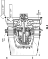
Fig. 1 is a partial cross-sectional view of an embodiment of a generator assembly in accordance with this disclosure; -
Fig. 2 is a cross-sectional view of a portion of the embodiment ofFig. 1 , showing a spray orifice directed at an interior surface of an electrical connector; -
Fig. 3 is a cross-sectional view of a portion of the embodiment ofFig. 1 , showing a spray orifice directed at an interior surface of an air line fitting, and a spray orifice directed at a cap; -
Fig. 4A is a cross-sectional view of a portion of the embodiment ofFig. 1 , showing an orifice tube having a plurality of spray orifices directed at a respective interior surface of a respective terminal insulator; -
Fig. 4B is a transverse cross-sectional view of the embodiment ofFig. 4A ; -
Fig. 5 is a cross-sectional view of the embodiment ofFig. 1 , shown disposed in a tail cone of a turbomachine; and -
Fig. 6 is a partially sectioned perspective view of the embodiment ofFig. 5 . - Reference will now be made to the drawings wherein like reference numerals identify similar structural features or aspects of the subject disclosure. For purposes of explanation and illustration, and not limitation, an illustrative view of an embodiment of a generator assembly in accordance with the disclosure is shown in
Fig. 1 and is designated generally byreference character 100. Other embodiments and/or aspects of this disclosure are shown inFigs. 2-6 . Certain embodiments described herein can be used to enable use of elastomeric seals in a tail cone generator assembly. - Referring to
Figs. 1-4B generally, agenerator assembly 100 for a high temperature environment that exceeds a seal temperature limit in operation can include agenerator housing 101 enclosing one or more generator components (e.g., electrical machine components such as coils, stators, cores, rotors, etc.). Thegenerator assembly 100 can also include one or more attachedcomponents housing 101. - The
assembly 100 can include one ormore seals components generator housing 101. Theassembly 100 can include anoil circuit 114 within thehousing 101 configured to circulate oil (e.g., via a pump that pressurizes oil). For example, oil can be circulated within thehousing 101 and be gravitationally directed to abottom sump 115 of thehousing 101. Theassembly 100 can include one or moreoil spray orifices housing 101 and in fluid communication with theoil circuit 114. Each of the one or moreoil spray orifices components components more seals more seals - For example, the one or
more seals more seals more seals - In certain embodiments, the high temperature environment can be a hot turbine exhaust environment. For example, the high temperature environment can be over 1,000 degrees F (e.g., about 1250 degrees F) in operation. In certain embodiments, the
oil circuit 114 can be configured to provide cooling to one or more generator components (e.g., astator 116 as shown inFig. 2 ) within thehousing 101. The one ormore spray orifices respective seal - Referring to
Fig. 2 , the one or more attachedcomponents electrical connector 203. The one ormore seals electrical connector seal 213, for example. Thespray orifice 217 can be directed toward an interior side of theelectrical connector 203 to spray oil thereon to cool theseal 213. - Referring to
Fig. 3 , the one or more attachedcomponents air line fitting 305. The one ormore seals fitting seal 313. Thespray orifice 319 can be directed toward an interior side of the air line fitting 305 to spray oil thereon to cool theseal 313. Thespray orifice 319 can be angled relative to the fitting 305, for example, and can spray in inside channel of the fitting 305. The oil received by theoil spray orifice 319 can be received from a stator portion of theoil circuit 114. - In certain embodiments, the
assembly 100 can further include an oil line fitting 307. In certain embodiments, e.g., as shown the oil line fitting 307 does not have an oil spray orifice directed thereto. For example, because oil is already flowing through the oil line fitting 307, the oilline fitting seal 308 stays cool. Any other suitable oil circuit component may not require an associate spray orifice also (e.g., thesump 115, for example) - The one or more attached
components cap 325 bolted to thehousing 101. The one ormore seals cap seal 327. Thespray orifice 321 can be directed toward an interior side of the cap 325 (e.g., near the seal 327) to spray oil thereon to cool theseal 327. - Referring to
Figs. 4A and4B , the one or more attachedcomponents lead insulators 411 arranged in one or more groups (e.g., a line of threeinsulators 411 havingterminals 412 disposed therein). Theoil circuit 114 can include anorifice tube 429 for each group. Theorifice tube 429 can have aterminal spray orifice 423 defined therein directed at a respective terminallead insulator 411, e.g., as shown. Each terminallead insulator 411 can include a plurality ofseals 413, for example, e.g., as shown. As shown, theorifice tube 429 can have threespray orifices 423, each one directed for spraying at a respectiveterminal insulator 411. Theassembly 100 can include fourtubes 429 spaced evenly, such that there are twelve totalterminal insulators 411 /terminals 412. - Certain examples of attached components having seals are disclosed above. However, it is contemplated that any other suitable components, attached to the
housing 101 or otherwise located on or within thehousing 101 can be cooled using a spray orifice to maintain a temperature below a critical temperature. - In accordance with at least one aspect of this disclosure, referring additionally to
Figs. 5 and6 , a turbomachine (not shown in entirety) can include a tailcone generator assembly 500 disposed in antail cone 501 and exposed to an environment that exceeds a seal temperature limit in operation (e.g., turbine exhaust gases). The tailcone generator assembly 500 can be or include anysuitable assembly 100 disclosed herein, e.g., as described above. - Embodiments can spray oil in the area around o-rings to convectively cool each o-ring. The size of spray orifices can be a function of supply pressure and desired cooling effect, and a person having ordinary skill in the art can determine what sizes, pressures, and amount of flow is needed for a particular application without undue experimentation. For example, in an aircraft related application, the orifices can be designed to use a minimum amount required for suitable cooling to reduce weight and pump losses, for example.
- Embodiments can include a scavenge pump connected to the
sump 115 at the bottom of the housing, for example. Oil within the housing can make its way due to gravity to thesump 115, and then flow to a heat exchanger to be cooled and reused. In a turbine application, ambient temperature can be about 500 degrees C which would melt standard elastomer o-rings. - Embodiments allow for the use of standard low cost fluoroelastomer seals (e.g., Viton™ GLT o-rings) which can perform during -40°C engine cold starts while also staying below the elastomer temperature limit while operating in the high ambient temperature (e.g., in a tail cone of a turbomachine).
- Those having ordinary skill in the art understand that any numerical values disclosed herein can be exact values or can be values within a range. Further, any terms of approximation (e.g., "about", "approximately", "around") used in this disclosure can mean the stated value within a range. For example, in certain embodiments, the range can be within (plus or minus) 20%, or within 10%, or within 5%, or within 2%, or within any other suitable percentage or number as appreciated by those having ordinary skill in the art (e.g., for known tolerance limits or error ranges).
- The articles "a", "an", and "the" as used herein and in the appended claims are used herein to refer to one or to more than one (i.e., to at least one) of the grammatical object of the article unless the context clearly indicates otherwise. By way of example, "an element" means one element or more than one element.
- The phrase "and/or," as used herein in the specification and in the claims, should be understood to mean "either or both" of the elements so conjoined, i.e., elements that are conjunctively present in some cases and disjunctively present in other cases. Multiple elements listed with "and/or" should be construed in the same fashion, i.e., "one or more" of the elements so conjoined. Other elements may optionally be present other than the elements specifically identified by the "and/or" clause, whether related or unrelated to those elements specifically identified. Thus, as a non-limiting example, a reference to "A and/or B", when used in conjunction with open-ended language such as "comprising" can refer, in one embodiment, to A only (optionally including elements other than B); in another embodiment, to B only (optionally including elements other than A); in yet another embodiment, to both A and B (optionally including other elements); etc.
- As used herein in the specification and in the claims, "or" should be understood to have the same meaning as "and/or" as defined above. For example, when separating items in a list, "or" or "and/or" shall be interpreted as being inclusive, i.e., the inclusion of at least one, but also including more than one, of a number or list of elements, and, optionally, additional unlisted items. Only terms clearly indicated to the contrary, such as "only one of" or "exactly one of," or, when used in the claims, "consisting of," will refer to the inclusion of exactly one element of a number or list of elements. In general, the term "or" as used herein shall only be interpreted as indicating exclusive alternatives (i.e., "one or the other but not both") when preceded by terms of exclusivity, such as "either," "one of," "only one of," or "exactly one of."
- Any suitable combination(s) of any disclosed embodiments and/or any suitable portion(s) thereof are contemplated herein as appreciated by those having ordinary skill in the art in view of this disclosure.
- The embodiments of the present disclosure, as described above and shown in the drawings, provide for improvement in the art to which they pertain. While the subject disclosure includes reference to certain embodiments, those skilled in the art will readily appreciate that changes and/or modifications may be made thereto without departing from the spirit and scope of the subject disclosure.
Claims (12)
- A generator assembly (100) for a high temperature environment that exceeds a seal temperature limit in operation, the assembly including:a generator housing (101) enclosing one or more generator components;one or more attached components (203, 305, 307, 309, 411) sealed to the housing;one or more seals (213, 313, 327, 413) disposed between each of the one or more attached components (203, 305, 307, 309, 411) and the generator housing (101);an oil circuit (114) within the housing configured to circulate oil; andone or more oil spray orifices (217, 319, 321, 423) within the housing and in fluid communication with the oil circuit (114), each of the one or more oil spray orifices (217, 319, 321, 423) directed at an interior portion of the one or more attached components (203, 305, 307, 309, 411) and/or an interior housing area adjacent the one or more attached components (203, 305, 307, 309, 411) to provide oil spray thereto for cooling each of the one or more seals (213, 313, 327, 413) to maintain the one or more seals (213, 313, 327, 413) below the seal temperature limit.
- The assembly of claim 1, wherein the one or more seals (213, 313, 327, 413) are elastomeric.
- The assembly of claim 2, wherein the high temperature environment is a hot turbine exhaust environment.
- The assembly of claim 3, wherein the high temperature environment is over 537.78 degrees C (1,000 degrees F) in operation.
- The assembly of claim 4, wherein the oil circuit (114) is configured to provide cooling to one or more generator components within the housing.
- The assembly of claim 5, wherein the one or more attached components (203, 305, 307, 309, 411) include an electrical connector, wherein the one or more seals (213, 313, 327, 413) include an electrical connector seal.
- The assembly of claim 5, wherein the one or more attached components (203, 305, 307, 309, 411) include an air line fitting, wherein the one or more seals (213, 313, 327, 413) include an air line fitting seal.
- The assembly of claim 7, further comprising an oil line fitting, wherein the oil line fitting does not have an oil spray orifice directed thereto.
- The assembly of claim 5, wherein the one or more attached components (203, 305, 307, 309, 411) include a cap bolted to the housing, wherein the one or more seals (213, 313, 327, 413) include a cap seal.
- The assembly of claim 5, wherein the one or more attached components (203, 305, 307, 309, 411) include a plurality of terminal lead insulators arranged in one or more groups, wherein the oil circuit (114) includes an orifice tube for each group, each orifice tube having a spray orifice defined therein directed at a respective terminal lead insulator.
- The assembly of claim 9, wherein each terminal lead insulator includes a plurality of seals.
- A turbomachine, comprising:
a tail cone generator assembly disposed in a tail cone and exposed to an environment that exceeds a seal temperature limit in operation, wherein the tail cone generator assembly is a generator assembly as claimed in any preceding claim.
Applications Claiming Priority (1)
| Application Number | Priority Date | Filing Date | Title |
|---|---|---|---|
| US18/105,747 US12323027B2 (en) | 2023-02-03 | 2023-02-03 | Seal cooling systems |
Publications (2)
| Publication Number | Publication Date |
|---|---|
| EP4411117A1 true EP4411117A1 (en) | 2024-08-07 |
| EP4411117B1 EP4411117B1 (en) | 2025-10-01 |
Family
ID=89772031
Family Applications (1)
| Application Number | Title | Priority Date | Filing Date |
|---|---|---|---|
| EP24155052.4A Active EP4411117B1 (en) | 2023-02-03 | 2024-01-31 | Seal cooling systems |
Country Status (2)
| Country | Link |
|---|---|
| US (1) | US12323027B2 (en) |
| EP (1) | EP4411117B1 (en) |
Families Citing this family (2)
| Publication number | Priority date | Publication date | Assignee | Title |
|---|---|---|---|---|
| EP4220906A1 (en) * | 2022-01-27 | 2023-08-02 | MAHLE International GmbH | Stator for an electric machine, production method for the same and motor vehicle component having such a stator |
| US12323027B2 (en) * | 2023-02-03 | 2025-06-03 | Hamilton Sundstrand Corporation | Seal cooling systems |
Citations (4)
| Publication number | Priority date | Publication date | Assignee | Title |
|---|---|---|---|---|
| EP3708788A1 (en) * | 2019-03-15 | 2020-09-16 | Hamilton Sundstrand Corporation | Temperature control device for tail cone mounted generator |
| EP3708787A1 (en) * | 2019-03-15 | 2020-09-16 | Hamilton Sundstrand Corporation | Plug in fluid cooled electrical connections for tail cone mounted generator |
| EP3879074A1 (en) * | 2020-03-09 | 2021-09-15 | Hamilton Sundstrand Corporation | Tail cone assembly for a gas turbine engine and mounted generator |
| US11371521B2 (en) * | 2019-04-10 | 2022-06-28 | Borgwarner Inc. | High temperature face seal |
Family Cites Families (15)
| Publication number | Priority date | Publication date | Assignee | Title |
|---|---|---|---|---|
| US4712029A (en) | 1986-12-22 | 1987-12-08 | Sundstrand Corporation | Generator high temperature electrical lead assembly |
| US5593165A (en) * | 1994-09-20 | 1997-01-14 | Allison Engine Company, Inc. | Circumferential flow channel for carbon seal runner cooling |
| US6196790B1 (en) * | 1998-12-17 | 2001-03-06 | United Technologies Corporation | Seal assembly for an intershaft seal in a gas turbine engine |
| US6628024B1 (en) | 2002-07-30 | 2003-09-30 | Honeywell International, Inc. | Hermetically sealed feed-through assembly for gas turbine engine starter generators and related methods |
| US7687928B2 (en) * | 2006-06-14 | 2010-03-30 | Smiths Aerospace, Llc | Dual-structured aircraft engine starter/generator |
| CN104254671B (en) | 2012-04-27 | 2020-03-17 | 通用电气公司 | Semi-sleeve metal seal integral with a tube |
| WO2014138617A1 (en) * | 2013-03-08 | 2014-09-12 | United Technologies Corporation | Fluid-cooled seal arrangement for a gas turbine engine |
| US9051882B2 (en) * | 2013-03-15 | 2015-06-09 | Rolls-Royce Corporation | Seals for a gas turbine engine |
| US9631508B2 (en) * | 2013-06-13 | 2017-04-25 | Pratt & Whitney Canada Corp. | Internally cooled seal runner |
| US10502094B2 (en) * | 2014-07-22 | 2019-12-10 | United Technologies Corporation | Bearing compartment sealing system with passive cooling |
| US10753219B2 (en) * | 2015-05-26 | 2020-08-25 | Pratt & Whitney Canada Corp. | Internally cooled seal runner and method of cooling seal runner of a gas turbine engine |
| US11065825B2 (en) * | 2018-12-05 | 2021-07-20 | Raytheon Technologies Corporation | High temperature composite seal |
| US11371441B2 (en) * | 2019-06-07 | 2022-06-28 | Raytheon Technologies Corporation | Translating fluid delivery device |
| US12203412B2 (en) * | 2022-06-10 | 2025-01-21 | Rtx Corporation | Turbine engine shaft plug |
| US12323027B2 (en) * | 2023-02-03 | 2025-06-03 | Hamilton Sundstrand Corporation | Seal cooling systems |
-
2023
- 2023-02-03 US US18/105,747 patent/US12323027B2/en active Active
-
2024
- 2024-01-31 EP EP24155052.4A patent/EP4411117B1/en active Active
Patent Citations (4)
| Publication number | Priority date | Publication date | Assignee | Title |
|---|---|---|---|---|
| EP3708788A1 (en) * | 2019-03-15 | 2020-09-16 | Hamilton Sundstrand Corporation | Temperature control device for tail cone mounted generator |
| EP3708787A1 (en) * | 2019-03-15 | 2020-09-16 | Hamilton Sundstrand Corporation | Plug in fluid cooled electrical connections for tail cone mounted generator |
| US11371521B2 (en) * | 2019-04-10 | 2022-06-28 | Borgwarner Inc. | High temperature face seal |
| EP3879074A1 (en) * | 2020-03-09 | 2021-09-15 | Hamilton Sundstrand Corporation | Tail cone assembly for a gas turbine engine and mounted generator |
Also Published As
| Publication number | Publication date |
|---|---|
| US12323027B2 (en) | 2025-06-03 |
| EP4411117B1 (en) | 2025-10-01 |
| US20240291344A1 (en) | 2024-08-29 |
Similar Documents
| Publication | Publication Date | Title |
|---|---|---|
| EP4411117B1 (en) | Seal cooling systems | |
| US11247779B2 (en) | Embedded electric machine | |
| CA3033178C (en) | Embedded electric machine | |
| US11707998B2 (en) | Electrical plug connector and electric plug-in connection | |
| US9551349B2 (en) | Circulating dielectric oil cooling system for canned bearings and canned electronics | |
| US9850817B2 (en) | Controller cooling arrangement | |
| EP3712404A1 (en) | Turbine engine configuration including pylon mounted heat exchanger | |
| US10968830B2 (en) | Systems and methods for cooling electronics and electrical machinery in a hybrid electric aircraft | |
| EP3203039A1 (en) | Gas turbine engine cooling system, corresponding gas turbine engine and method of cooling | |
| US11346247B2 (en) | Turbine engine including a heat exchanger formed in a platform | |
| EP3002432A1 (en) | A mounting arrangement for an electrical harness | |
| US8046987B2 (en) | Air cooled core mounted ignition system | |
| US11482368B2 (en) | Hybrid thermal management of electronics | |
| US12172769B2 (en) | System and method for cooling a fluid of a lubrication or cooling circuit of a drive unit of an aircraft, and aircraft propulsion engine provided with such a cooling system | |
| US20200383233A1 (en) | Aircraft power electronic unit and method of cooling | |
| US20160177783A1 (en) | Housing support nut connection | |
| US10069370B2 (en) | Seal oil supply device for dynamo-electric machine and seal oil supply method | |
| EP4418504A1 (en) | Generator housings and assemblies | |
| US12568609B2 (en) | Thermal management systems for rectifier assemblies | |
| EP2712057A2 (en) | Motor assembly cooling arrangement and method of cooling a motor assembly | |
| EP2287933A2 (en) | Heat pump for high temperature environments | |
| US11746700B2 (en) | Thermal management for a motor feeder |
Legal Events
| Date | Code | Title | Description |
|---|---|---|---|
| PUAI | Public reference made under article 153(3) epc to a published international application that has entered the european phase |
Free format text: ORIGINAL CODE: 0009012 |
|
| STAA | Information on the status of an ep patent application or granted ep patent |
Free format text: STATUS: THE APPLICATION HAS BEEN PUBLISHED |
|
| STAA | Information on the status of an ep patent application or granted ep patent |
Free format text: STATUS: REQUEST FOR EXAMINATION WAS MADE |
|
| AK | Designated contracting states |
Kind code of ref document: A1 Designated state(s): AL AT BE BG CH CY CZ DE DK EE ES FI FR GB GR HR HU IE IS IT LI LT LU LV MC ME MK MT NL NO PL PT RO RS SE SI SK SM TR |
|
| 17P | Request for examination filed |
Effective date: 20240730 |
|
| RBV | Designated contracting states (corrected) |
Designated state(s): AL AT BE BG CH CY CZ DE DK EE ES FI FR GB GR HR HU IE IS IT LI LT LU LV MC ME MK MT NL NO PL PT RO RS SE SI SK SM TR |
|
| GRAP | Despatch of communication of intention to grant a patent |
Free format text: ORIGINAL CODE: EPIDOSNIGR1 |
|
| STAA | Information on the status of an ep patent application or granted ep patent |
Free format text: STATUS: GRANT OF PATENT IS INTENDED |
|
| RIC1 | Information provided on ipc code assigned before grant |
Ipc: F01D 25/30 20060101ALI20241217BHEP Ipc: F01D 25/24 20060101ALI20241217BHEP Ipc: F01D 25/12 20060101ALI20241217BHEP Ipc: F01D 15/10 20060101AFI20241217BHEP |
|
| INTG | Intention to grant announced |
Effective date: 20250115 |
|
| GRAJ | Information related to disapproval of communication of intention to grant by the applicant or resumption of examination proceedings by the epo deleted |
Free format text: ORIGINAL CODE: EPIDOSDIGR1 |
|
| STAA | Information on the status of an ep patent application or granted ep patent |
Free format text: STATUS: REQUEST FOR EXAMINATION WAS MADE |
|
| GRAP | Despatch of communication of intention to grant a patent |
Free format text: ORIGINAL CODE: EPIDOSNIGR1 |
|
| STAA | Information on the status of an ep patent application or granted ep patent |
Free format text: STATUS: GRANT OF PATENT IS INTENDED |
|
| INTC | Intention to grant announced (deleted) | ||
| INTG | Intention to grant announced |
Effective date: 20250514 |
|
| GRAS | Grant fee paid |
Free format text: ORIGINAL CODE: EPIDOSNIGR3 |
|
| GRAA | (expected) grant |
Free format text: ORIGINAL CODE: 0009210 |
|
| STAA | Information on the status of an ep patent application or granted ep patent |
Free format text: STATUS: THE PATENT HAS BEEN GRANTED |
|
| AK | Designated contracting states |
Kind code of ref document: B1 Designated state(s): AL AT BE BG CH CY CZ DE DK EE ES FI FR GB GR HR HU IE IS IT LI LT LU LV MC ME MK MT NL NO PL PT RO RS SE SI SK SM TR |
|
| REG | Reference to a national code |
Ref country code: GB Ref legal event code: FG4D Ref country code: CH Ref legal event code: F10 Free format text: ST27 STATUS EVENT CODE: U-0-0-F10-F00 (AS PROVIDED BY THE NATIONAL OFFICE) Effective date: 20251001 |
|
| REG | Reference to a national code |
Ref country code: IE Ref legal event code: FG4D |
|
| REG | Reference to a national code |
Ref country code: DE Ref legal event code: R096 Ref document number: 602024000762 Country of ref document: DE |
|
| PGFP | Annual fee paid to national office [announced via postgrant information from national office to epo] |
Ref country code: FR Payment date: 20251217 Year of fee payment: 3 |
|
| REG | Reference to a national code |
Ref country code: NL Ref legal event code: MP Effective date: 20251001 |
|
| REG | Reference to a national code |
Ref country code: AT Ref legal event code: MK05 Ref document number: 1842699 Country of ref document: AT Kind code of ref document: T Effective date: 20251001 |
|
| PG25 | Lapsed in a contracting state [announced via postgrant information from national office to epo] |
Ref country code: NL Free format text: LAPSE BECAUSE OF FAILURE TO SUBMIT A TRANSLATION OF THE DESCRIPTION OR TO PAY THE FEE WITHIN THE PRESCRIBED TIME-LIMIT Effective date: 20251001 |
|
| PG25 | Lapsed in a contracting state [announced via postgrant information from national office to epo] |
Ref country code: ES Free format text: LAPSE BECAUSE OF FAILURE TO SUBMIT A TRANSLATION OF THE DESCRIPTION OR TO PAY THE FEE WITHIN THE PRESCRIBED TIME-LIMIT Effective date: 20251001 |
|
| REG | Reference to a national code |
Ref country code: LT Ref legal event code: MG9D |
|
| PG25 | Lapsed in a contracting state [announced via postgrant information from national office to epo] |
Ref country code: NO Free format text: LAPSE BECAUSE OF FAILURE TO SUBMIT A TRANSLATION OF THE DESCRIPTION OR TO PAY THE FEE WITHIN THE PRESCRIBED TIME-LIMIT Effective date: 20260101 |
|
| PG25 | Lapsed in a contracting state [announced via postgrant information from national office to epo] |
Ref country code: FI Free format text: LAPSE BECAUSE OF FAILURE TO SUBMIT A TRANSLATION OF THE DESCRIPTION OR TO PAY THE FEE WITHIN THE PRESCRIBED TIME-LIMIT Effective date: 20251001 Ref country code: HR Free format text: LAPSE BECAUSE OF FAILURE TO SUBMIT A TRANSLATION OF THE DESCRIPTION OR TO PAY THE FEE WITHIN THE PRESCRIBED TIME-LIMIT Effective date: 20251001 Ref country code: AT Free format text: LAPSE BECAUSE OF FAILURE TO SUBMIT A TRANSLATION OF THE DESCRIPTION OR TO PAY THE FEE WITHIN THE PRESCRIBED TIME-LIMIT Effective date: 20251001 |
|
| PG25 | Lapsed in a contracting state [announced via postgrant information from national office to epo] |
Ref country code: RS Free format text: LAPSE BECAUSE OF FAILURE TO SUBMIT A TRANSLATION OF THE DESCRIPTION OR TO PAY THE FEE WITHIN THE PRESCRIBED TIME-LIMIT Effective date: 20260101 |
|
| PG25 | Lapsed in a contracting state [announced via postgrant information from national office to epo] |
Ref country code: IS Free format text: LAPSE BECAUSE OF FAILURE TO SUBMIT A TRANSLATION OF THE DESCRIPTION OR TO PAY THE FEE WITHIN THE PRESCRIBED TIME-LIMIT Effective date: 20260201 |
|
| PG25 | Lapsed in a contracting state [announced via postgrant information from national office to epo] |
Ref country code: CZ Free format text: LAPSE BECAUSE OF FAILURE TO SUBMIT A TRANSLATION OF THE DESCRIPTION OR TO PAY THE FEE WITHIN THE PRESCRIBED TIME-LIMIT Effective date: 20251001 Ref country code: PT Free format text: LAPSE BECAUSE OF FAILURE TO SUBMIT A TRANSLATION OF THE DESCRIPTION OR TO PAY THE FEE WITHIN THE PRESCRIBED TIME-LIMIT Effective date: 20260202 |
|
| PG25 | Lapsed in a contracting state [announced via postgrant information from national office to epo] |
Ref country code: PL Free format text: LAPSE BECAUSE OF FAILURE TO SUBMIT A TRANSLATION OF THE DESCRIPTION OR TO PAY THE FEE WITHIN THE PRESCRIBED TIME-LIMIT Effective date: 20251001 |
|
| PG25 | Lapsed in a contracting state [announced via postgrant information from national office to epo] |
Ref country code: LV Free format text: LAPSE BECAUSE OF FAILURE TO SUBMIT A TRANSLATION OF THE DESCRIPTION OR TO PAY THE FEE WITHIN THE PRESCRIBED TIME-LIMIT Effective date: 20251001 |
|
| PG25 | Lapsed in a contracting state [announced via postgrant information from national office to epo] |
Ref country code: BG Free format text: LAPSE BECAUSE OF FAILURE TO SUBMIT A TRANSLATION OF THE DESCRIPTION OR TO PAY THE FEE WITHIN THE PRESCRIBED TIME-LIMIT Effective date: 20251001 |