EP4411113A1 - Replaceable fluid line termination fittings - Google Patents
Replaceable fluid line termination fittings Download PDFInfo
- Publication number
- EP4411113A1 EP4411113A1 EP24155376.7A EP24155376A EP4411113A1 EP 4411113 A1 EP4411113 A1 EP 4411113A1 EP 24155376 A EP24155376 A EP 24155376A EP 4411113 A1 EP4411113 A1 EP 4411113A1
- Authority
- EP
- European Patent Office
- Prior art keywords
- distal
- proximal
- channel
- fitting
- body portion
- Prior art date
- Legal status (The legal status is an assumption and is not a legal conclusion. Google has not performed a legal analysis and makes no representation as to the accuracy of the status listed.)
- Pending
Links
Images





Classifications
-
- F—MECHANICAL ENGINEERING; LIGHTING; HEATING; WEAPONS; BLASTING
- F01—MACHINES OR ENGINES IN GENERAL; ENGINE PLANTS IN GENERAL; STEAM ENGINES
- F01D—NON-POSITIVE DISPLACEMENT MACHINES OR ENGINES, e.g. STEAM TURBINES
- F01D9/00—Stators
- F01D9/06—Fluid supply conduits to nozzles or the like
- F01D9/065—Fluid supply or removal conduits traversing the working fluid flow, e.g. for lubrication-, cooling-, or sealing fluids
-
- F—MECHANICAL ENGINEERING; LIGHTING; HEATING; WEAPONS; BLASTING
- F16—ENGINEERING ELEMENTS AND UNITS; GENERAL MEASURES FOR PRODUCING AND MAINTAINING EFFECTIVE FUNCTIONING OF MACHINES OR INSTALLATIONS; THERMAL INSULATION IN GENERAL
- F16L—PIPES; JOINTS OR FITTINGS FOR PIPES; SUPPORTS FOR PIPES, CABLES OR PROTECTIVE TUBING; MEANS FOR THERMAL INSULATION IN GENERAL
- F16L41/00—Branching pipes; Joining pipes to walls
- F16L41/08—Joining pipes to walls or pipes, the joined pipe axis being perpendicular to the plane of a wall or to the axis of another pipe
-
- F—MECHANICAL ENGINEERING; LIGHTING; HEATING; WEAPONS; BLASTING
- F01—MACHINES OR ENGINES IN GENERAL; ENGINE PLANTS IN GENERAL; STEAM ENGINES
- F01D—NON-POSITIVE DISPLACEMENT MACHINES OR ENGINES, e.g. STEAM TURBINES
- F01D25/00—Component parts, details, or accessories, not provided for in, or of interest apart from, other groups
-
- F—MECHANICAL ENGINEERING; LIGHTING; HEATING; WEAPONS; BLASTING
- F01—MACHINES OR ENGINES IN GENERAL; ENGINE PLANTS IN GENERAL; STEAM ENGINES
- F01D—NON-POSITIVE DISPLACEMENT MACHINES OR ENGINES, e.g. STEAM TURBINES
- F01D25/00—Component parts, details, or accessories, not provided for in, or of interest apart from, other groups
- F01D25/18—Lubricating arrangements
-
- F—MECHANICAL ENGINEERING; LIGHTING; HEATING; WEAPONS; BLASTING
- F02—COMBUSTION ENGINES; HOT-GAS OR COMBUSTION-PRODUCT ENGINE PLANTS
- F02C—GAS-TURBINE PLANTS; AIR INTAKES FOR JET-PROPULSION PLANTS; CONTROLLING FUEL SUPPLY IN AIR-BREATHING JET-PROPULSION PLANTS
- F02C7/00—Features, components parts, details or accessories, not provided for in, or of interest apart form groups F02C1/00 - F02C6/00; Air intakes for jet-propulsion plants
-
- F—MECHANICAL ENGINEERING; LIGHTING; HEATING; WEAPONS; BLASTING
- F16—ENGINEERING ELEMENTS AND UNITS; GENERAL MEASURES FOR PRODUCING AND MAINTAINING EFFECTIVE FUNCTIONING OF MACHINES OR INSTALLATIONS; THERMAL INSULATION IN GENERAL
- F16L—PIPES; JOINTS OR FITTINGS FOR PIPES; SUPPORTS FOR PIPES, CABLES OR PROTECTIVE TUBING; MEANS FOR THERMAL INSULATION IN GENERAL
- F16L15/00—Screw-threaded joints; Forms of screw-threads for such joints
- F16L15/04—Screw-threaded joints; Forms of screw-threads for such joints with additional sealings
-
- F—MECHANICAL ENGINEERING; LIGHTING; HEATING; WEAPONS; BLASTING
- F05—INDEXING SCHEMES RELATING TO ENGINES OR PUMPS IN VARIOUS SUBCLASSES OF CLASSES F01-F04
- F05D—INDEXING SCHEME FOR ASPECTS RELATING TO NON-POSITIVE-DISPLACEMENT MACHINES OR ENGINES, GAS-TURBINES OR JET-PROPULSION PLANTS
- F05D2220/00—Application
- F05D2220/30—Application in turbines
- F05D2220/32—Application in turbines in gas turbines
-
- F—MECHANICAL ENGINEERING; LIGHTING; HEATING; WEAPONS; BLASTING
- F05—INDEXING SCHEMES RELATING TO ENGINES OR PUMPS IN VARIOUS SUBCLASSES OF CLASSES F01-F04
- F05D—INDEXING SCHEME FOR ASPECTS RELATING TO NON-POSITIVE-DISPLACEMENT MACHINES OR ENGINES, GAS-TURBINES OR JET-PROPULSION PLANTS
- F05D2220/00—Application
- F05D2220/50—Application for auxiliary power units (APU's)
-
- F—MECHANICAL ENGINEERING; LIGHTING; HEATING; WEAPONS; BLASTING
- F05—INDEXING SCHEMES RELATING TO ENGINES OR PUMPS IN VARIOUS SUBCLASSES OF CLASSES F01-F04
- F05D—INDEXING SCHEME FOR ASPECTS RELATING TO NON-POSITIVE-DISPLACEMENT MACHINES OR ENGINES, GAS-TURBINES OR JET-PROPULSION PLANTS
- F05D2220/00—Application
- F05D2220/70—Application in combination with
- F05D2220/76—Application in combination with an electrical generator
-
- F—MECHANICAL ENGINEERING; LIGHTING; HEATING; WEAPONS; BLASTING
- F05—INDEXING SCHEMES RELATING TO ENGINES OR PUMPS IN VARIOUS SUBCLASSES OF CLASSES F01-F04
- F05D—INDEXING SCHEME FOR ASPECTS RELATING TO NON-POSITIVE-DISPLACEMENT MACHINES OR ENGINES, GAS-TURBINES OR JET-PROPULSION PLANTS
- F05D2240/00—Components
- F05D2240/90—Mounting on supporting structures or systems
-
- F—MECHANICAL ENGINEERING; LIGHTING; HEATING; WEAPONS; BLASTING
- F05—INDEXING SCHEMES RELATING TO ENGINES OR PUMPS IN VARIOUS SUBCLASSES OF CLASSES F01-F04
- F05D—INDEXING SCHEME FOR ASPECTS RELATING TO NON-POSITIVE-DISPLACEMENT MACHINES OR ENGINES, GAS-TURBINES OR JET-PROPULSION PLANTS
- F05D2260/00—Function
- F05D2260/60—Fluid transfer
Definitions
- This disclosure relates to fluid line termination fittings.
- Certain systems e.g., aircraft generators can utilize a sealed fluid system (e.g., for oil circulation, for air circulation).
- the fluid system can include an angled hose end for sealing to a generator housing, for example.
- a fluid line termination fitting for a tail cone generator can include a distal body portion configured to insert into a fluid circuit opening of a tail cone generator housing and a proximal body portion configured to receive a male fluid connector.
- the fitting can include a radial extension disposed axially between the distal portion and the proximal portion.
- the radial extension can extend radially outwardly relative to the distal portion and proximal portion to limit insertion of the distal body portion into the opening of the tail cone generator housing.
- the fitting can include a channel structure defining a flow channel through the distal body portion and the proximal body portion.
- the channel structure can include a proximal channel portion in fluid communication with a proximal opening and a distal channel portion in fluid communication with a distal opening.
- the fitting can include a threaded section in the proximal channel portion and configured to thread to the male fluid connector and an angled sealing face distal of the threaded section and extending radially inward between the proximal channel portion and the distal channel portion.
- the angled sealing face can be configured to flushly mate with a complimentary angled surface on the male fluid connector.
- the angled sealing face can be or include a 37 degree surface, for example. Other suitable degree angles are contemplated herein that provide a complimentary sealing face to flushly mate with the complimentary angled surface of the male fluid connector to provide a sealed relationship.
- the distal body portion can include a seal channel defined therein and configured to receive a sealing member to seal the distal body portion to the tail cone generator housing.
- the fitting can include the seal.
- the channel structure can include a relief annulus defined in the proximal channel portion proximal of and/or adjacent to the angled sealing face.
- the distal channel portion can have smaller inner diameter than the proximal channel portion, for example.
- the radial extension can be configured to mount to the tail cone generator housing.
- the fitting can be a single piece. In certain embodiments, the fitting can be metallic. Any suitable number of pieces attached together or formed together and/or any suitable material are contemplated herein.
- a tail cone generator assembly can include a tail cone generator configured to be disposed within a tail cone of a turbomachine.
- the tail cone generator can include a tail cone generator housing having a fluid circuit opening.
- the tail cone generator assembly can include a fluid line termination fitting attached to the tail cone generator housing.
- the fluid termination fitting can include any suitable fitting disclosed herein, e.g., as described above.
- a fluid line termination fitting can be applied for any suitable application.
- Embodiments of a fluid line termination fitting can be or include any suitable fitting disclosed herein, e.g., as described above.
- FIG. 1 an illustrative view of an embodiment of a fitting in accordance with the disclosure is shown in Fig. 1 and is designated generally by reference character 100.
- FIGs. 2-8 Other embodiments and/or aspects of this disclosure are shown in Figs. 2-8 .
- Certain embodiments described herein can be used to provide a serviceable and replaceable sealed termination, for example, to mitigate housing scrapping and/or reworking.
- a fluid line termination fitting 100 for a tail cone generator 300 can include a distal body portion 101 configured to insert into a fluid circuit opening 103 of a tail cone generator housing 105.
- the distal body portion 101 can be slip fit into the opening 103 with a tight clearance fit (e.g., 1-2 mil).
- the fitting 100 can include a proximal body portion 107 configured to receive a male fluid connector 200 (e.g., as shown in Fig. 2 ).
- the fitting 100 can include a radial extension 109 disposed axially between the distal portion 101 and the proximal portion 107.
- the radial extension 109 can extend radially outwardly relative to the distal portion 101 and proximal portion 107 to limit insertion of the distal body portion 101 into the opening 103 of the tail cone generator housing 105.
- the fitting 100 can include a channel structure (e.g., the interior surfaces of the fitting 100) defining a flow channel through the distal body portion 101 and the proximal body portion 107 (e.g., from a proximal opening 111 to a distal opening 113.
- the channel structure can include a proximal channel portion 115 in fluid communication with a proximal opening 111 and a distal channel portion 117 in fluid communication with a distal opening 113.
- the fitting 100 can include a threaded section 119 in the proximal channel portion 115 which can be configured to thread to the male fluid connector 200.
- the fitting 100 can also include an angled sealing face 121 distal of the threaded section 119 and extending radially inward (e.g., forming a channel area reduction) between the proximal channel portion and the distal channel portion.
- the angled sealing face 121 can be configured to flushly mate with a complimentary angled surface 223 on the male fluid connector 200.
- the angled sealing face 121 can be or include a 37 degree surface, for example. Other suitable degree angles are contemplated herein that provide a complimentary sealing face to flushly mate with the complimentary angled surface 223 of the male fluid connector 200 to provide a sealed relationship.
- the distal body portion 101 can include a seal channel 125 defined therein and configured to receive a sealing member 127 to seal the distal body portion 101 to the tail cone generator housing 105.
- the fitting 100 can include the seal 127.
- the channel structure can include a relief annulus 129 defined in the proximal channel portion 115 proximal of and/or adjacent to the angled sealing face 121.
- the distal channel portion 117 can have smaller inner diameter than the proximal channel portion 115, for example (e.g., as shown).
- the radial extension 109 can be configured to mount to the tail cone generator housing 105.
- the fitting 100 can be a single piece.
- the fitting can be metallic (e.g., stainless steel), for example. Any suitable number of pieces attached together or formed together and/or any suitable material are contemplated herein.
- Fig. 3 is a front perspective view of a tail cone generator assembly in accordance with this disclosure, shown having the fitting of Fig. 1 disposed thereon.
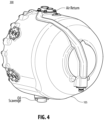
- Fig. 4 is a rear perspective view of the embodiment of Fig. 3 .
- Fig. 5 is a perspective cross-sectional view of the embodiment of Fig. 3 .
- Fig. 6 is a cross-sectional view of the assembly of Fig. 3 , shown disposed within the tail cone of a turbomachine.
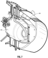
- Fig. 7 is a partially sectioned perspective view of the embodiment of Fig. 6 .
- Fig. 8 is a perspective view showing a fluid line assembly within a strut, which connect to the fitting of Fig. 1 as shown in Fig. 2 , for example.
- a tail cone generator assembly can include a tail cone generator 300 configured to be disposed within a tail cone 600 of a turbomachine.
- the tail cone generator 300 can include a tail cone generator housing 105 having a fluid circuit opening 103.
- the tail cone generator assembly can include a fluid line termination fitting 100 attached to the tail cone generator housing 105.
- the fluid termination fitting 100 can include any suitable fitting disclosed herein, e.g., as described above.
- the bypass air can be 300°F, but the exhaust can be about 1250°F around the insulated tail cone for example.
- feeders, air/oil lines, and excitation wiring can be routed through service struts that bridge across exhaust flow.
- the fluid line termination fitting 100 can be applied to any suitable application and is not limited to tail cone generation application.
- Embodiments of a general fluid line termination fitting can be or include any suitable fitting disclosed herein, e.g., as described above.
- Embodiments of a fitting can include an inner diameter at a top that is threaded.
- Embodiments of a fitting can include an annular inner cut (e.g., a thread relief).
- Embodiments of a fitting can include radial extension (e.g., a flange) for stopping and also bolting the fitting to a housing (e.g., at two points).
- Embodiments can provide a metal to metal seal when connected to the male connector.
- Embodiments of a fitting can include a 37 degree surface, but allow mounting without a tube nut, for example.
- Embodiments of a fitting can be used for oil-in, oil-scavenge, and air return ports, for example, on a generator.
- Embodiments can provide replaceable ports on a generator to mitigate housing scrap/rework costs, for example.
- Embodiments of a fitting can receive and support 37° flare tube ends.
- Embodiments can bottom onto port seats through thin crush seals, for example.
- Embodiments of a fitting can be attached to an investment cast/machined titanium housing, allowing replacement of the fittings instead of scrapping and reworking of the expensive housing.
- Embodiments can provide a replaceable design was conceived to mitigate scrapping expensive castings should a manufacturing error occur or if the metal sealing surface is damaged by foreign object debris during aircraft/engine mating of a 37° male tube fitting installation
- any numerical values disclosed herein can be exact values or can be values within a range. Further, any terms of approximation (e.g., “about”, “approximately”, “around”) used in this disclosure can mean the stated value within a range. For example, in certain embodiments, the range can be within (plus or minus) 20%, or within 10%, or within 5%, or within 2%, or within any other suitable percentage or number as appreciated by those having ordinary skill in the art (e.g., for known tolerance limits or error ranges).
- a reference to "A and/or B", when used in conjunction with open-ended language such as “comprising” can refer, in one embodiment, to A only (optionally including elements other than B); in another embodiment, to B only (optionally including elements other than A); in yet another embodiment, to both A and B (optionally including other elements); etc.
Landscapes
- Engineering & Computer Science (AREA)
- General Engineering & Computer Science (AREA)
- Mechanical Engineering (AREA)
- Chemical & Material Sciences (AREA)
- Combustion & Propulsion (AREA)
- Physics & Mathematics (AREA)
- Fluid Mechanics (AREA)
- Structures Of Non-Positive Displacement Pumps (AREA)
- Gasket Seals (AREA)
Abstract
A fluid line termination fitting for a tail cone generator can include a distal body portion (101) configured to insert into a fluid circuit opening of a tail cone generator housing and a proximal body portion (107) configured to receive a male fluid connector. The fitting can include a radial extension (109) disposed axially between the distal portion and the proximal portion. The radial extension (109) can extend radially outwardly relative to the distal portion and proximal portion to limit insertion of the distal body portion (101) into the opening of the tail cone generator housing. The fitting can include a channel structure defining a flow channel through the distal body portion (101) and the proximal body portion (107). The channel structure can include a proximal channel portion in fluid communication with a proximal opening and a distal channel portion in fluid communication with a distal opening. The fitting can include a threaded section (119) in the proximal channel portion and configured to thread to the male fluid connector and an angled sealing face (121) distal of the threaded section (119) and extending radially inward between the proximal channel portion and the distal channel portion. The angled sealing face (121) can be configured to flushly mate with a complimentary angled surface on the male fluid connector.
Description
- This disclosure relates to fluid line termination fittings.
- Certain systems, e.g., aircraft generators can utilize a sealed fluid system (e.g., for oil circulation, for air circulation). The fluid system can include an angled hose end for sealing to a generator housing, for example.
- Conventional methods and systems have generally been considered satisfactory for their intended purpose. However, there is still a need in the art for improvements. The present disclosure provides a solution for this need.
- A fluid line termination fitting for a tail cone generator can include a distal body portion configured to insert into a fluid circuit opening of a tail cone generator housing and a proximal body portion configured to receive a male fluid connector. The fitting can include a radial extension disposed axially between the distal portion and the proximal portion. The radial extension can extend radially outwardly relative to the distal portion and proximal portion to limit insertion of the distal body portion into the opening of the tail cone generator housing. The fitting can include a channel structure defining a flow channel through the distal body portion and the proximal body portion. The channel structure can include a proximal channel portion in fluid communication with a proximal opening and a distal channel portion in fluid communication with a distal opening. The fitting can include a threaded section in the proximal channel portion and configured to thread to the male fluid connector and an angled sealing face distal of the threaded section and extending radially inward between the proximal channel portion and the distal channel portion. The angled sealing face can be configured to flushly mate with a complimentary angled surface on the male fluid connector.
- The angled sealing face can be or include a 37 degree surface, for example. Other suitable degree angles are contemplated herein that provide a complimentary sealing face to flushly mate with the complimentary angled surface of the male fluid connector to provide a sealed relationship.
- The distal body portion can include a seal channel defined therein and configured to receive a sealing member to seal the distal body portion to the tail cone generator housing. In certain embodiments, the fitting can include the seal. The channel structure can include a relief annulus defined in the proximal channel portion proximal of and/or adjacent to the angled sealing face. The distal channel portion can have smaller inner diameter than the proximal channel portion, for example.
- The radial extension can be configured to mount to the tail cone generator housing. The fitting can be a single piece. In certain embodiments, the fitting can be metallic. Any suitable number of pieces attached together or formed together and/or any suitable material are contemplated herein.
- In accordance with at least one aspect of this disclosure, a tail cone generator assembly can include a tail cone generator configured to be disposed within a tail cone of a turbomachine. The tail cone generator can include a tail cone generator housing having a fluid circuit opening. The tail cone generator assembly can include a fluid line termination fitting attached to the tail cone generator housing. The fluid termination fitting can include any suitable fitting disclosed herein, e.g., as described above.
- In accordance with at least one aspect of this disclosure, a fluid line termination fitting can be applied for any suitable application. Embodiments of a fluid line termination fitting can be or include any suitable fitting disclosed herein, e.g., as described above.
- These and other features of the embodiments of the subject disclosure will become more readily apparent to those skilled in the art from the following detailed description taken in conjunction with the drawings.
- So that those skilled in the art to which the subject disclosure appertains will readily understand how to make and use the devices and methods of the subject disclosure without undue experimentation, embodiments thereof will be described in detail herein below with reference to certain figures, wherein:
-
Fig. 1 is a cross-sectional view of an embodiment of a fitting in accordance with this disclosure, shown disposed in and attached to an embodiment of a tail cone generator housing; -
Fig. 2 is a cross-sectional view of the embodiment ofFig. 1 , shown having a male fluid connector threaded into and sealed against an angled sealing face; -
Fig. 3 is a front perspective view of a tail cone generator assembly in accordance with this disclosure, shown having the fitting ofFig. 1 disposed thereon; -
Fig. 4 is a rear perspective view of the embodiment ofFig. 3 ; -
Fig. 5 is a perspective cross-sectional view of the embodiment ofFig. 3 ; -
Fig. 6 is a cross-sectional view of the assembly ofFig. 3 , shown disposed within the tail cone of a turbomachine; -
Fig. 7 is a partially sectioned perspective view of the embodiment ofFig. 6 ; and -
Fig. 8 is a perspective view showing a fluid line assembly within a strut, which connect to the fitting ofFig. 1 as shown inFig. 2 , for example. - Reference will now be made to the drawings wherein like reference numerals identify similar structural features or aspects of the subject disclosure. For purposes of explanation and illustration, and not limitation, an illustrative view of an embodiment of a fitting in accordance with the disclosure is shown in
Fig. 1 and is designated generally byreference character 100. Other embodiments and/or aspects of this disclosure are shown inFigs. 2-8 . Certain embodiments described herein can be used to provide a serviceable and replaceable sealed termination, for example, to mitigate housing scrapping and/or reworking. - Referring to
Fig. 1 , a fluid line termination fitting 100 for atail cone generator 300 can include adistal body portion 101 configured to insert into a fluid circuit opening 103 of a tailcone generator housing 105. Thedistal body portion 101 can be slip fit into the opening 103 with a tight clearance fit (e.g., 1-2 mil). Thefitting 100 can include aproximal body portion 107 configured to receive a male fluid connector 200 (e.g., as shown inFig. 2 ). - The
fitting 100 can include aradial extension 109 disposed axially between thedistal portion 101 and theproximal portion 107. Theradial extension 109 can extend radially outwardly relative to thedistal portion 101 andproximal portion 107 to limit insertion of thedistal body portion 101 into theopening 103 of the tailcone generator housing 105. - The
fitting 100 can include a channel structure (e.g., the interior surfaces of the fitting 100) defining a flow channel through thedistal body portion 101 and the proximal body portion 107 (e.g., from aproximal opening 111 to adistal opening 113. The channel structure can include aproximal channel portion 115 in fluid communication with aproximal opening 111 and adistal channel portion 117 in fluid communication with adistal opening 113. Thefitting 100 can include a threadedsection 119 in theproximal channel portion 115 which can be configured to thread to themale fluid connector 200. Thefitting 100 can also include an angled sealingface 121 distal of the threadedsection 119 and extending radially inward (e.g., forming a channel area reduction) between the proximal channel portion and the distal channel portion. The angled sealingface 121 can be configured to flushly mate with a complimentaryangled surface 223 on themale fluid connector 200. - The
angled sealing face 121 can be or include a 37 degree surface, for example. Other suitable degree angles are contemplated herein that provide a complimentary sealing face to flushly mate with the complimentaryangled surface 223 of themale fluid connector 200 to provide a sealed relationship. - The
distal body portion 101 can include aseal channel 125 defined therein and configured to receive a sealingmember 127 to seal thedistal body portion 101 to the tailcone generator housing 105. In certain embodiments, thefitting 100 can include theseal 127. The channel structure can include arelief annulus 129 defined in theproximal channel portion 115 proximal of and/or adjacent to the angled sealingface 121. In certain embodiments, thedistal channel portion 117 can have smaller inner diameter than theproximal channel portion 115, for example (e.g., as shown). - The
radial extension 109 can be configured to mount to the tailcone generator housing 105. In certain embodiments, the fitting 100 can be a single piece. In certain embodiments, the fitting can be metallic (e.g., stainless steel), for example. Any suitable number of pieces attached together or formed together and/or any suitable material are contemplated herein. -
Fig. 3 is a front perspective view of a tail cone generator assembly in accordance with this disclosure, shown having the fitting ofFig. 1 disposed thereon.Fig. 4 is a rear perspective view of the embodiment ofFig. 3 .Fig. 5 is a perspective cross-sectional view of the embodiment ofFig. 3 .Fig. 6 is a cross-sectional view of the assembly ofFig. 3 , shown disposed within the tail cone of a turbomachine.Fig. 7 is a partially sectioned perspective view of the embodiment ofFig. 6 .Fig. 8 is a perspective view showing a fluid line assembly within a strut, which connect to the fitting ofFig. 1 as shown inFig. 2 , for example. - In accordance with at least one aspect of this disclosure, referring to
Fig. 3 , a tail cone generator assembly can include atail cone generator 300 configured to be disposed within atail cone 600 of a turbomachine. Thetail cone generator 300 can include a tailcone generator housing 105 having afluid circuit opening 103. The tail cone generator assembly can include a fluid line termination fitting 100 attached to the tailcone generator housing 105. The fluid termination fitting 100 can include any suitable fitting disclosed herein, e.g., as described above. In tail cone systems, the bypass air can be 300°F, but the exhaust can be about 1250°F around the insulated tail cone for example. As shown inFigs. 6-8 , feeders, air/oil lines, and excitation wiring can be routed through service struts that bridge across exhaust flow. - In accordance with at least one aspect of this disclosure, the fluid line termination fitting 100 can be applied to any suitable application and is not limited to tail cone generation application. Embodiments of a general fluid line termination fitting can be or include any suitable fitting disclosed herein, e.g., as described above.
- Embodiments of a fitting can include an inner diameter at a top that is threaded. Embodiments of a fitting can include an annular inner cut (e.g., a thread relief). Embodiments of a fitting can include radial extension (e.g., a flange) for stopping and also bolting the fitting to a housing (e.g., at two points). Embodiments can provide a metal to metal seal when connected to the male connector. Embodiments of a fitting can include a 37 degree surface, but allow mounting without a tube nut, for example. Embodiments of a fitting can be used for oil-in, oil-scavenge, and air return ports, for example, on a generator.
- Embodiments can provide replaceable ports on a generator to mitigate housing scrap/rework costs, for example. Embodiments of a fitting can receive and support 37° flare tube ends. Embodiments can bottom onto port seats through thin crush seals, for example. Embodiments of a fitting can be attached to an investment cast/machined titanium housing, allowing replacement of the fittings instead of scrapping and reworking of the expensive housing. Embodiments can provide a replaceable design was conceived to mitigate scrapping expensive castings should a manufacturing error occur or if the metal sealing surface is damaged by foreign object debris during aircraft/engine mating of a 37° male tube fitting installation
- Those having ordinary skill in the art understand that any numerical values disclosed herein can be exact values or can be values within a range. Further, any terms of approximation (e.g., "about", "approximately", "around") used in this disclosure can mean the stated value within a range. For example, in certain embodiments, the range can be within (plus or minus) 20%, or within 10%, or within 5%, or within 2%, or within any other suitable percentage or number as appreciated by those having ordinary skill in the art (e.g., for known tolerance limits or error ranges).
- The articles "a", "an", and "the" as used herein and in the appended claims are used herein to refer to one or to more than one (i.e., to at least one) of the grammatical object of the article unless the context clearly indicates otherwise. By way of example, "an element" means one element or more than one element.
- The phrase "and/or," as used herein in the specification and in the claims, should be understood to mean "either or both" of the elements so conjoined, i.e., elements that are conjunctively present in some cases and disjunctively present in other cases. Multiple elements listed with "and/or" should be construed in the same fashion, i.e., "one or more" of the elements so conjoined. Other elements may optionally be present other than the elements specifically identified by the "and/or" clause, whether related or unrelated to those elements specifically identified. Thus, as a non-limiting example, a reference to "A and/or B", when used in conjunction with open-ended language such as "comprising" can refer, in one embodiment, to A only (optionally including elements other than B); in another embodiment, to B only (optionally including elements other than A); in yet another embodiment, to both A and B (optionally including other elements); etc.
- As used herein in the specification and in the claims, "or" should be understood to have the same meaning as "and/or" as defined above. For example, when separating items in a list, "or" or "and/or" shall be interpreted as being inclusive, i.e., the inclusion of at least one, but also including more than one, of a number or list of elements, and, optionally, additional unlisted items. Only terms clearly indicated to the contrary, such as "only one of" or "exactly one of," or, when used in the claims, "consisting of," will refer to the inclusion of exactly one element of a number or list of elements. In general, the term "or" as used herein shall only be interpreted as indicating exclusive alternatives (i.e., "one or the other but not both") when preceded by terms of exclusivity, such as "either," "one of," "only one of," or "exactly one of."
- Any suitable combination(s) of any disclosed embodiments and/or any suitable portion(s) thereof are contemplated herein as appreciated by those having ordinary skill in the art in view of this disclosure.
- The embodiments of the present disclosure, as described above and shown in the drawings, provide for improvement in the art to which they pertain. While the subject disclosure includes reference to certain embodiments, those skilled in the art will readily appreciate that changes and/or modifications may be made thereto without departing from the spirit and scope of the subject disclosure.
Claims (15)
- A fluid line termination fitting for a tail cone generator, comprising:a distal body portion (101) configured to insert into a fluid circuit opening of a tail cone generator housing;a proximal body portion (107) configured to receive a male fluid connector;a radial extension (109) disposed axially between the distal portion and the proximal portion, the radial extension (109) extending radially outwardly relative to the distal portion and proximal portion to limit insertion of the distal body portion (101) into the opening of the tail cone generator housing;a channel structure defining a flow channel through the distal body portion (101) and the proximal body portion (107), the channel structure including a proximal channel portion in fluid communication with a proximal opening and a distal channel portion in fluid communication with a distal opening;a threaded section (119) in the proximal channel portion and configured to thread to the male fluid connector; andan angled sealing face (121) distal of the threaded section (119) and extending radially inward between the proximal channel portion and the distal channel portion, wherein the angled sealing face (121) is configured to flushly mate with a complimentary angled surface on the male fluid connector.
- The fitting of claim 1, wherein the angled sealing face (121) is or includes a 37 degree surface.
- The fitting of claim 1 or 2, wherein the distal body portion (101) includes a seal channel defined therein and configured to receive a sealing member to seal the distal body portion (101) to the tail cone generator housing and/or further comprising the seal.
- The fitting of any preceding claim, wherein the channel structure includes a relief annulus defined in the proximal channel portion proximal of and/or adjacent to the angled sealing face (121).
- The fitting of any preceding claim, wherein the radial extension (109) is configured to mount to the tail cone generator housing.
- The fitting of any preceding claim, wherein the distal channel portion has a smaller inner diameter than the proximal channel portion.
- The fitting of any preceding claim, wherein the fitting is a single piece, and/ wherein the fitting is metallic.
- A tail cone generator assembly, comprising:a tail cone generator configured to be disposed within a tail cone of a turbomachine, the tail cone generator including a tail cone generator housing having a fluid circuit opening;a fluid line termination fitting attached to the tail cone generator housing, the fluid termination fitting comprising:a distal body portion (101) inserted into the fluid circuit opening of a tail cone generator housing;a proximal body portion (107) configured to receive a male fluid connector;a radial extension (109) disposed axially between the distal portion and the proximal portion, the radial extension (109) extending radially outwardly relative to the distal portion and proximal portion to limit insertion of the distal body portion (101) into the opening of the tail cone generator housing;a channel structure defining a flow channel through the distal body portion (101) and the proximal body portion (107), the channel structure including a proximal channel portion in fluid communication with a proximal opening and a distal channel portion in fluid communication with a distal opening;a threaded section (119) in the proximal channel portion and configured to thread to the male fluid connector; andan angled sealing face (121) distal of the threaded section and extending radially inward between the proximal channel portion and the distal channel portion, wherein the angled sealing face (121) is configured to flushly mate with a complimentary angled surface on the male fluid connector.
- The assembly of claim 8, wherein the angled sealing face (121) is or includes a 37 degree surface.
- The assembly of claim 8 or 9, wherein the distal body portion (101) includes a seal channel defined therein and configured to receive a sealing member to seal the distal body portion (101) to the tail cone generator housing.
- The assembly any of claims 8 to 10, further comprising the seal.
- The assembly of any of claims 8 to 11, wherein the channel structure includes a relief annulus defined in the proximal channel portion proximal of and/or adjacent to the angled sealing face (121), and/or wherein the radial extension (109) is configured to mount to the tail cone generator housing.
- The assembly of any of claims 8 to 12, wherein the distal channel portion has a smaller inner diameter than the proximal channel portion.
- The assembly of any of claims 8 to 130, wherein the fitting is a single piece, and/or wherein the fitting is metallic.
- A fluid line termination fitting, comprising:a distal body portion (101) configured to insert into a fluid circuit opening of a housing;a proximal body portion (107) configured to receive a male fluid connector;a radial extension (109) disposed axially between the distal portion and the proximal portion, the radial extension (109) extending radially outwardly relative to the distal portion and proximal portion to limit insertion of the distal body portion (101) into the opening of the housing;a channel structure defining a flow channel through the distal body portion (101) and the proximal body portion (107), the channel structure including a proximal channel portion in fluid communication with a proximal opening and a distal channel portion in fluid communication with a distal opening;a threaded section (119) in the proximal channel portion and configured to thread to the male fluid connector; andan angled sealing face (121) distal of the threaded section (119) and extending radially inward between the proximal channel portion and the distal channel portion, wherein the angled sealing face (121) is configured to flushly mate with a complimentary angled surface on the male fluid connector.
Applications Claiming Priority (1)
| Application Number | Priority Date | Filing Date | Title |
|---|---|---|---|
| US18/105,746 US20240263725A1 (en) | 2023-02-03 | 2023-02-03 | Replaceable fluid line termination fittings |
Publications (1)
| Publication Number | Publication Date |
|---|---|
| EP4411113A1 true EP4411113A1 (en) | 2024-08-07 |
Family
ID=89834488
Family Applications (1)
| Application Number | Title | Priority Date | Filing Date |
|---|---|---|---|
| EP24155376.7A Pending EP4411113A1 (en) | 2023-02-03 | 2024-02-01 | Replaceable fluid line termination fittings |
Country Status (2)
| Country | Link |
|---|---|
| US (1) | US20240263725A1 (en) |
| EP (1) | EP4411113A1 (en) |
Families Citing this family (1)
| Publication number | Priority date | Publication date | Assignee | Title |
|---|---|---|---|---|
| US12523321B2 (en) * | 2021-04-06 | 2026-01-13 | Aero-Stream LLC | Riser and ingress device assembly for septic tank system |
Citations (5)
| Publication number | Priority date | Publication date | Assignee | Title |
|---|---|---|---|---|
| US6102577A (en) * | 1998-10-13 | 2000-08-15 | Pratt & Whitney Canada Corp. | Isolated oil feed |
| EP3632800A1 (en) * | 2018-10-03 | 2020-04-08 | United Technologies Corporation | Fluid tube assembly for gas turbine engine |
| EP3730741A1 (en) * | 2019-04-18 | 2020-10-28 | United Technologies Corporation | Fluid transfer tube with tool receptacle and corresponding assembly |
| EP3879074A1 (en) * | 2020-03-09 | 2021-09-15 | Hamilton Sundstrand Corporation | Tail cone assembly for a gas turbine engine and mounted generator |
| CA3157653A1 (en) * | 2021-04-30 | 2022-10-30 | Pratt & Whitney Canada Corp. | Sweep flow structures for fuel systems |
Family Cites Families (10)
| Publication number | Priority date | Publication date | Assignee | Title |
|---|---|---|---|---|
| US4280721A (en) * | 1979-11-14 | 1981-07-28 | United Technologies Corporation | Angularly lockable fitting |
| US5330237A (en) * | 1992-03-04 | 1994-07-19 | Kabushiki Kaisha Toyoda Jidoshokki Seisakusho | Pipe joint for hydraulic pipe |
| DE10017254C1 (en) * | 2000-04-06 | 2001-09-13 | Itt Mfg Enterprises Inc | Cap screw bolt, to link a vehicle brake hose to a brake line, is tightened in a prismatic opening coaxial to the longitudinal axis of the center drilling through the screw bolt with a high torque transfer between the tool and the bolt |
| US6439616B1 (en) * | 2001-03-29 | 2002-08-27 | General Electric Company | Anti-rotation retainer for a conduit |
| JP5464171B2 (en) * | 2011-05-25 | 2014-04-09 | 株式会社デンソー | Fluid passage connection device |
| DE202015103455U1 (en) * | 2015-07-01 | 2015-07-14 | Ti Automotive Engineering Centre (Heidelberg) Gmbh | Connecting element for connecting a pipe end to a component of an air conditioning system |
| US10393303B2 (en) * | 2017-02-06 | 2019-08-27 | United Technologies Corporation | Threaded fitting for tube |
| US10641115B2 (en) * | 2017-08-29 | 2020-05-05 | United Technologies Corporation | Segmented conduit with airfoil geometry |
| US11274770B2 (en) * | 2019-04-18 | 2022-03-15 | Raytheon Technologies Corporation | Monolithic fluid transfer tube |
| FR3101372B1 (en) * | 2019-09-27 | 2021-10-01 | Safran Aircraft Engines | AIRCRAFT TURBOMACHINE |
-
2023
- 2023-02-03 US US18/105,746 patent/US20240263725A1/en active Pending
-
2024
- 2024-02-01 EP EP24155376.7A patent/EP4411113A1/en active Pending
Patent Citations (5)
| Publication number | Priority date | Publication date | Assignee | Title |
|---|---|---|---|---|
| US6102577A (en) * | 1998-10-13 | 2000-08-15 | Pratt & Whitney Canada Corp. | Isolated oil feed |
| EP3632800A1 (en) * | 2018-10-03 | 2020-04-08 | United Technologies Corporation | Fluid tube assembly for gas turbine engine |
| EP3730741A1 (en) * | 2019-04-18 | 2020-10-28 | United Technologies Corporation | Fluid transfer tube with tool receptacle and corresponding assembly |
| EP3879074A1 (en) * | 2020-03-09 | 2021-09-15 | Hamilton Sundstrand Corporation | Tail cone assembly for a gas turbine engine and mounted generator |
| CA3157653A1 (en) * | 2021-04-30 | 2022-10-30 | Pratt & Whitney Canada Corp. | Sweep flow structures for fuel systems |
Also Published As
| Publication number | Publication date |
|---|---|
| US20240263725A1 (en) | 2024-08-08 |
Similar Documents
| Publication | Publication Date | Title |
|---|---|---|
| US6358001B1 (en) | Turbine frame assembly | |
| US8596959B2 (en) | Oil tube with integrated heat shield | |
| US5263314A (en) | Fuel leakage protection system for gas turbine engine | |
| US6439841B1 (en) | Turbine frame assembly | |
| EP3358139B1 (en) | Threaded fitting for tube | |
| EP4411113A1 (en) | Replaceable fluid line termination fittings | |
| KR102261267B1 (en) | Fitting device, arrangement and method | |
| US11009039B2 (en) | Intermittent spigot joint for gas turbine engine casing connection | |
| EP1270875A2 (en) | Turbine leaf seal mounting with headless pins | |
| EP2434107A2 (en) | Anti-fret liner assembly for a turbine engine | |
| EP3358140B1 (en) | Fitting for multiwall tube | |
| EP3992434B1 (en) | Service tube assembly for a gas turbine engine | |
| KR20140071942A (en) | Turbomachine diaphragm ring with packing retainment apparatus | |
| US5450719A (en) | Gas turbine engine rear magnetic or foil bearing cooling using exhaust eductor | |
| EP1144894B1 (en) | Secured coupling assembly and method of preventing loosening | |
| US7331612B2 (en) | Low profile tension style flexible joint | |
| US10494937B2 (en) | Inner ring for an annular guide vane assembly of a turbomachine | |
| WO2017027961A1 (en) | Oil scupper system for bearing housing of gas turbine engine | |
| US7845649B2 (en) | Methods and apparatus to facilitate sealing high pressure joints | |
| US11143341B2 (en) | Balking tab to control duct coupling clocking | |
| EP3502526B1 (en) | Air seal attachment | |
| EP4086496B1 (en) | Transfer tube assembly | |
| EP3073168B1 (en) | Double wall tube fitting with an integrated diagnostic port | |
| US11220927B2 (en) | Assembly for a turbomachine | |
| FR2993312A1 (en) | Oil removal device for separating oil and air from air-oil mixture in e.g. turbojet engine, of aircraft, has C shaped annular cowling covering nut and upstream end part of low pressure turbine shaft and located downstream of upstream flange |
Legal Events
| Date | Code | Title | Description |
|---|---|---|---|
| PUAI | Public reference made under article 153(3) epc to a published international application that has entered the european phase |
Free format text: ORIGINAL CODE: 0009012 |
|
| STAA | Information on the status of an ep patent application or granted ep patent |
Free format text: STATUS: THE APPLICATION HAS BEEN PUBLISHED |
|
| AK | Designated contracting states |
Kind code of ref document: A1 Designated state(s): AL AT BE BG CH CY CZ DE DK EE ES FI FR GB GR HR HU IE IS IT LI LT LU LV MC ME MK MT NL NO PL PT RO RS SE SI SK SM TR |
|
| STAA | Information on the status of an ep patent application or granted ep patent |
Free format text: STATUS: REQUEST FOR EXAMINATION WAS MADE |
|
| 17P | Request for examination filed |
Effective date: 20250206 |