EP4411106A1 - Tie rod-locking nut assembly and gas turbine including same - Google Patents
Tie rod-locking nut assembly and gas turbine including same Download PDFInfo
- Publication number
- EP4411106A1 EP4411106A1 EP24154668.8A EP24154668A EP4411106A1 EP 4411106 A1 EP4411106 A1 EP 4411106A1 EP 24154668 A EP24154668 A EP 24154668A EP 4411106 A1 EP4411106 A1 EP 4411106A1
- Authority
- EP
- European Patent Office
- Prior art keywords
- locking nut
- jack bolt
- tie rod
- turbine
- jack
- Prior art date
- Legal status (The legal status is an assumption and is not a legal conclusion. Google has not performed a legal analysis and makes no representation as to the accuracy of the status listed.)
- Granted
Links
Images




Classifications
-
- F—MECHANICAL ENGINEERING; LIGHTING; HEATING; WEAPONS; BLASTING
- F01—MACHINES OR ENGINES IN GENERAL; ENGINE PLANTS IN GENERAL; STEAM ENGINES
- F01D—NON-POSITIVE DISPLACEMENT MACHINES OR ENGINES, e.g. STEAM TURBINES
- F01D5/00—Blades; Blade-carrying members; Heating, heat-insulating, cooling or antivibration means on the blades or the members
- F01D5/02—Blade-carrying members, e.g. rotors
- F01D5/025—Fixing blade carrying members on shafts
-
- F—MECHANICAL ENGINEERING; LIGHTING; HEATING; WEAPONS; BLASTING
- F01—MACHINES OR ENGINES IN GENERAL; ENGINE PLANTS IN GENERAL; STEAM ENGINES
- F01D—NON-POSITIVE DISPLACEMENT MACHINES OR ENGINES, e.g. STEAM TURBINES
- F01D25/00—Component parts, details, or accessories, not provided for in, or of interest apart from, other groups
- F01D25/28—Supporting or mounting arrangements, e.g. for turbine casing
-
- F—MECHANICAL ENGINEERING; LIGHTING; HEATING; WEAPONS; BLASTING
- F01—MACHINES OR ENGINES IN GENERAL; ENGINE PLANTS IN GENERAL; STEAM ENGINES
- F01D—NON-POSITIVE DISPLACEMENT MACHINES OR ENGINES, e.g. STEAM TURBINES
- F01D5/00—Blades; Blade-carrying members; Heating, heat-insulating, cooling or antivibration means on the blades or the members
- F01D5/02—Blade-carrying members, e.g. rotors
- F01D5/026—Shaft to shaft connections
-
- F—MECHANICAL ENGINEERING; LIGHTING; HEATING; WEAPONS; BLASTING
- F01—MACHINES OR ENGINES IN GENERAL; ENGINE PLANTS IN GENERAL; STEAM ENGINES
- F01D—NON-POSITIVE DISPLACEMENT MACHINES OR ENGINES, e.g. STEAM TURBINES
- F01D5/00—Blades; Blade-carrying members; Heating, heat-insulating, cooling or antivibration means on the blades or the members
- F01D5/02—Blade-carrying members, e.g. rotors
- F01D5/06—Rotors for more than one axial stage, e.g. of drum or multiple disc type; Details thereof, e.g. shafts, shaft connections
- F01D5/066—Connecting means for joining rotor-discs or rotor-elements together, e.g. by a central bolt, by clamps
-
- F—MECHANICAL ENGINEERING; LIGHTING; HEATING; WEAPONS; BLASTING
- F16—ENGINEERING ELEMENTS AND UNITS; GENERAL MEASURES FOR PRODUCING AND MAINTAINING EFFECTIVE FUNCTIONING OF MACHINES OR INSTALLATIONS; THERMAL INSULATION IN GENERAL
- F16B—DEVICES FOR FASTENING OR SECURING CONSTRUCTIONAL ELEMENTS OR MACHINE PARTS TOGETHER, e.g. NAILS, BOLTS, CIRCLIPS, CLAMPS, CLIPS OR WEDGES; JOINTS OR JOINTING
- F16B31/00—Screwed connections specially modified in view of tensile load; Break-bolts
- F16B31/04—Screwed connections specially modified in view of tensile load; Break-bolts for maintaining a tensile load
-
- F—MECHANICAL ENGINEERING; LIGHTING; HEATING; WEAPONS; BLASTING
- F16—ENGINEERING ELEMENTS AND UNITS; GENERAL MEASURES FOR PRODUCING AND MAINTAINING EFFECTIVE FUNCTIONING OF MACHINES OR INSTALLATIONS; THERMAL INSULATION IN GENERAL
- F16B—DEVICES FOR FASTENING OR SECURING CONSTRUCTIONAL ELEMENTS OR MACHINE PARTS TOGETHER, e.g. NAILS, BOLTS, CIRCLIPS, CLAMPS, CLIPS OR WEDGES; JOINTS OR JOINTING
- F16B37/00—Nuts or like thread-engaging members
- F16B37/14—Cap nuts; Nut caps or bolt caps
- F16B37/145—Sleeve nuts, e.g. combined with bolts
-
- F—MECHANICAL ENGINEERING; LIGHTING; HEATING; WEAPONS; BLASTING
- F16—ENGINEERING ELEMENTS AND UNITS; GENERAL MEASURES FOR PRODUCING AND MAINTAINING EFFECTIVE FUNCTIONING OF MACHINES OR INSTALLATIONS; THERMAL INSULATION IN GENERAL
- F16B—DEVICES FOR FASTENING OR SECURING CONSTRUCTIONAL ELEMENTS OR MACHINE PARTS TOGETHER, e.g. NAILS, BOLTS, CIRCLIPS, CLAMPS, CLIPS OR WEDGES; JOINTS OR JOINTING
- F16B39/00—Locking of screws, bolts or nuts
- F16B39/02—Locking of screws, bolts or nuts in which the locking takes place after screwing down
- F16B39/10—Locking of screws, bolts or nuts in which the locking takes place after screwing down by a plate, spring, wire or ring immovable with regard to the bolt or object and mainly perpendicular to the axis of the bolt
-
- F—MECHANICAL ENGINEERING; LIGHTING; HEATING; WEAPONS; BLASTING
- F16—ENGINEERING ELEMENTS AND UNITS; GENERAL MEASURES FOR PRODUCING AND MAINTAINING EFFECTIVE FUNCTIONING OF MACHINES OR INSTALLATIONS; THERMAL INSULATION IN GENERAL
- F16B—DEVICES FOR FASTENING OR SECURING CONSTRUCTIONAL ELEMENTS OR MACHINE PARTS TOGETHER, e.g. NAILS, BOLTS, CIRCLIPS, CLAMPS, CLIPS OR WEDGES; JOINTS OR JOINTING
- F16B39/00—Locking of screws, bolts or nuts
- F16B39/02—Locking of screws, bolts or nuts in which the locking takes place after screwing down
- F16B39/10—Locking of screws, bolts or nuts in which the locking takes place after screwing down by a plate, spring, wire or ring immovable with regard to the bolt or object and mainly perpendicular to the axis of the bolt
- F16B39/101—Locking of screws, bolts or nuts in which the locking takes place after screwing down by a plate, spring, wire or ring immovable with regard to the bolt or object and mainly perpendicular to the axis of the bolt with a plate, spring, wire or ring holding two or more nuts or bolt heads which are mainly in the same plane
-
- F—MECHANICAL ENGINEERING; LIGHTING; HEATING; WEAPONS; BLASTING
- F16—ENGINEERING ELEMENTS AND UNITS; GENERAL MEASURES FOR PRODUCING AND MAINTAINING EFFECTIVE FUNCTIONING OF MACHINES OR INSTALLATIONS; THERMAL INSULATION IN GENERAL
- F16B—DEVICES FOR FASTENING OR SECURING CONSTRUCTIONAL ELEMENTS OR MACHINE PARTS TOGETHER, e.g. NAILS, BOLTS, CIRCLIPS, CLAMPS, CLIPS OR WEDGES; JOINTS OR JOINTING
- F16B39/00—Locking of screws, bolts or nuts
- F16B39/22—Locking of screws, bolts or nuts in which the locking takes place during screwing down or tightening
- F16B39/24—Locking of screws, bolts or nuts in which the locking takes place during screwing down or tightening by means of washers, spring washers, or resilient plates that lock against the object
-
- F—MECHANICAL ENGINEERING; LIGHTING; HEATING; WEAPONS; BLASTING
- F16—ENGINEERING ELEMENTS AND UNITS; GENERAL MEASURES FOR PRODUCING AND MAINTAINING EFFECTIVE FUNCTIONING OF MACHINES OR INSTALLATIONS; THERMAL INSULATION IN GENERAL
- F16D—COUPLINGS FOR TRANSMITTING ROTATION; CLUTCHES; BRAKES
- F16D1/00—Couplings for rigidly connecting two coaxial shafts or other movable machine elements
- F16D1/06—Couplings for rigidly connecting two coaxial shafts or other movable machine elements for attachment of a member on a shaft or on a shaft-end
- F16D1/08—Couplings for rigidly connecting two coaxial shafts or other movable machine elements for attachment of a member on a shaft or on a shaft-end with clamping hub; with hub and longitudinal key
- F16D1/0876—Couplings for rigidly connecting two coaxial shafts or other movable machine elements for attachment of a member on a shaft or on a shaft-end with clamping hub; with hub and longitudinal key with axial keys and no other radial clamping
-
- F—MECHANICAL ENGINEERING; LIGHTING; HEATING; WEAPONS; BLASTING
- F02—COMBUSTION ENGINES; HOT-GAS OR COMBUSTION-PRODUCT ENGINE PLANTS
- F02C—GAS-TURBINE PLANTS; AIR INTAKES FOR JET-PROPULSION PLANTS; CONTROLLING FUEL SUPPLY IN AIR-BREATHING JET-PROPULSION PLANTS
- F02C3/00—Gas-turbine plants characterised by the use of combustion products as the working fluid
- F02C3/04—Gas-turbine plants characterised by the use of combustion products as the working fluid having a turbine driving a compressor
-
- F—MECHANICAL ENGINEERING; LIGHTING; HEATING; WEAPONS; BLASTING
- F05—INDEXING SCHEMES RELATING TO ENGINES OR PUMPS IN VARIOUS SUBCLASSES OF CLASSES F01-F04
- F05D—INDEXING SCHEME FOR ASPECTS RELATING TO NON-POSITIVE-DISPLACEMENT MACHINES OR ENGINES, GAS-TURBINES OR JET-PROPULSION PLANTS
- F05D2220/00—Application
- F05D2220/30—Application in turbines
- F05D2220/32—Application in turbines in gas turbines
-
- F—MECHANICAL ENGINEERING; LIGHTING; HEATING; WEAPONS; BLASTING
- F05—INDEXING SCHEMES RELATING TO ENGINES OR PUMPS IN VARIOUS SUBCLASSES OF CLASSES F01-F04
- F05D—INDEXING SCHEME FOR ASPECTS RELATING TO NON-POSITIVE-DISPLACEMENT MACHINES OR ENGINES, GAS-TURBINES OR JET-PROPULSION PLANTS
- F05D2240/00—Components
- F05D2240/20—Rotors
- F05D2240/24—Rotors for turbines
-
- F—MECHANICAL ENGINEERING; LIGHTING; HEATING; WEAPONS; BLASTING
- F05—INDEXING SCHEMES RELATING TO ENGINES OR PUMPS IN VARIOUS SUBCLASSES OF CLASSES F01-F04
- F05D—INDEXING SCHEME FOR ASPECTS RELATING TO NON-POSITIVE-DISPLACEMENT MACHINES OR ENGINES, GAS-TURBINES OR JET-PROPULSION PLANTS
- F05D2240/00—Components
- F05D2240/35—Combustors or associated equipment
-
- F—MECHANICAL ENGINEERING; LIGHTING; HEATING; WEAPONS; BLASTING
- F05—INDEXING SCHEMES RELATING TO ENGINES OR PUMPS IN VARIOUS SUBCLASSES OF CLASSES F01-F04
- F05D—INDEXING SCHEME FOR ASPECTS RELATING TO NON-POSITIVE-DISPLACEMENT MACHINES OR ENGINES, GAS-TURBINES OR JET-PROPULSION PLANTS
- F05D2250/00—Geometry
- F05D2250/10—Two-dimensional
- F05D2250/13—Two-dimensional trapezoidal
- F05D2250/131—Two-dimensional trapezoidal polygonal
-
- F—MECHANICAL ENGINEERING; LIGHTING; HEATING; WEAPONS; BLASTING
- F05—INDEXING SCHEMES RELATING TO ENGINES OR PUMPS IN VARIOUS SUBCLASSES OF CLASSES F01-F04
- F05D—INDEXING SCHEME FOR ASPECTS RELATING TO NON-POSITIVE-DISPLACEMENT MACHINES OR ENGINES, GAS-TURBINES OR JET-PROPULSION PLANTS
- F05D2250/00—Geometry
- F05D2250/10—Two-dimensional
- F05D2250/13—Two-dimensional trapezoidal
- F05D2250/132—Two-dimensional trapezoidal hexagonal
-
- F—MECHANICAL ENGINEERING; LIGHTING; HEATING; WEAPONS; BLASTING
- F05—INDEXING SCHEMES RELATING TO ENGINES OR PUMPS IN VARIOUS SUBCLASSES OF CLASSES F01-F04
- F05D—INDEXING SCHEME FOR ASPECTS RELATING TO NON-POSITIVE-DISPLACEMENT MACHINES OR ENGINES, GAS-TURBINES OR JET-PROPULSION PLANTS
- F05D2260/00—Function
- F05D2260/30—Retaining components in desired mutual position
- F05D2260/31—Retaining bolts or nuts
Definitions
- the present invention relates to a tie rod-locking nut assembly and a gas turbine including the same.
- a turbine is a mechanical device that obtains a rotational force by an impulsive force or reaction force using a flow of a compressible fluid such as steam or gas.
- a turbine may be a steam turbine using steam, or a gas turbine using a high temperature combustion gas.
- the gas turbine is mainly composed of a compressor, a combustor, and a turbine.
- the compressor is provided with an air inlet for introducing air, and a plurality of compressor vanes and compressor blades, which are alternately arranged in a compressor housing.
- the combustor supplies fuel to the compressed air compressed in the compressor and ignites a fuel-air mixture with a burner to produce a high temperature and high pressure combustion gas.
- the turbine has a plurality of turbine vanes and turbine blades disposed alternately in a turbine casing. Further, a rotor is arranged to pass through the center of the compressor, the combustor, the turbine and an exhaust chamber.
- Both ends of the rotor are rotatably supported by bearings.
- a plurality of disks is fixed to the rotor so that the respective blades are connected.
- a drive shaft such as a generator is connected to an end of the exhaust chamber.
- the compressed air compressed in the compressor is mixed with fuel and combusted to produce a high-temperature combustion gas in the combustor, which is then injected toward the turbine.
- the injected combustion gas passes through the turbine vanes and the turbine blades to generate a rotational force, which causes the rotor to rotate.
- an objective of the present invention is to provide a tie rod-locking nut assembly capable of preventing a tie rod-locking nut from being loosened during operation of a gas turbine, and a gas turbine including the same.
- the present invention provides a tie rod-locking nut assembly in accordance with claim 1 and a gas turbine in accordance with claim 10.
- Advantageous embodiments are subject to the dependent claims and the following description, referring to the drawings.
- a tie rod-locking nut assembly includes: a tie rod-locking nut engaged with or fastened to a jack bolt, e.g., in that the jack bolt is inserted or introduced into the tie rod-locking nut; a jack bolt-locking nut inserted between the tie rod-locking nut and the jack bolt; an anti-loosening washer formed to wrap around an outer circumferential surface of the jack bolt-locking nut to prevent loosening of the jack bolt-locking nut; and a locking plate formed to cover the anti-loosening washer and engaging with an outer circumferential surface of the tie rod.
- the anti-loosening washer may be configured for being coupled to the tie rod and may engaged with the jack bolt-locking nut such that rotation of the jack bolt-locking nut is prevented.
- the tie rod-locking nut may have a jack bolt-insertion hole formed at a position corresponding to a position in which the jack bolt is formed, and the jack bolt-insertion hole has a stepped portion formed at an end of the jack bolt-insertion hole.
- the jack bolt-locking nut has a shape of hollow pipe with both ends open and may be inserted into a gap formed between the stepped portion and the jack bolt during engagement with the jack bolt.
- the jack bolt-insertion hole may include a step dividing the jack bolt-insertion hole into an outer portion formed at an end of the jack bolt-insertion hole and an inner portion formed on an opposite side of the step, wherein the outer portion has a greater diameter than the inner portion.
- the outer portion herein, may also be referred to as stepped portion.
- the jack bolt-locking nut may be formed with a length greater than the stepped portion such that, when inserted into the gap, a distal end thereof is exposed externally from the tie rod-locking nut, wherein the jack bolt-locking nut is in a shape such that a cross-section of the jack bolt-locking nut has an outer circumference in a circular shape corresponding to the stepped portion and has an inner circumference in a preferably polygonal shape corresponding to the jack bolt.
- a contact area between the jack bolt-locking nut and the anti-loosening washer may be caulked.
- the anti-loosening washer may be a circular plate member having a plurality of insertion holes formed in positions corresponding to the plurality of jack bolt-locking nuts.
- an inner circumferential surface of the locking plate may be threaded to engage with the outer circumferential surface of the tie rod.
- a gas turbine in a second aspect of the present invention, includes: a compressor suctioning and compressing external air and having a plurality of compressor rotor disks; a combustor mixing fuel with compressed air and combusting an air-fuel mixture; a turbine section having a plurality of turbine blades mounted on a plurality of turbine rotor disks so that the turbine blades is rotated by the combustion gases discharged from the combustor; and a tie rod having one end engaged with a most upstream-side one of the compressor rotor disks and the other end engaged with a tie rod-locking nut assembly, the tie rod-locking nut assembly including: a tie rod-locking nut threaded onto a jack bolt formed; a jack bolt-locking nut inserted between the tie rod-locking nut and the jack bolt; an anti-loosening washer formed to wrap around an outer circumferential surface of the jack bolt-locking nut to prevent loosening of the jack bolt-locking nut
- the tie rod-locking nut may have a jack bolt-insertion hole formed at a position corresponding to a position in which the jack bolt is formed, and the jack bolt-insertion hole has a stepped portion formed at an end of the jack bolt-insertion hole.
- the jack bolt-locking nut may have a shape of hollow pipe with both ends open and may be inserted into a gap formed between the stepped portion and the jack bolt during engagement with the jack bolt.
- the jack bolt-locking nut may be formed with a length greater than the stepped portion such that, when inserted into the gap, a distal end thereof is exposed externally from the tie rod-locking nut, wherein the jack bolt-locking nut is in a shape such that a cross-section of the jack bolt-locking nut has an outer circumference in a circular shape corresponding to the stepped portion and has an inner circumference in a polygonal shape corresponding to the jack bolt.
- a contact area between the jack bolt-locking nut and the anti-loosening washer may be caulked.
- the anti-loosening washer may be a circular plate member having a plurality of insertion holes formed in positions corresponding to the plurality of jack bolt-locking nuts.
- an inner circumferential surface of the locking plate may be threaded to engage with the outer circumferential surface of the tie rod.
- FIG. 1 is a partially cut-away perspective view of a gas turbine according to an embodiment of the present invention
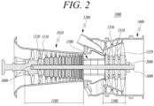
- FIG. 2 is a cross-sectional view illustrating a schematic structure of a gas turbine according to an embodiment of the present invention.
- a gas turbine 1000 includes a compressor 1100, a combustor 1200, and a turbine 1300.
- the compressor 1100 includes a plurality of compressor blades 1110 radially installed.
- the compressor 1100 rotates the compressor blade 1110 so that air flows while being compressed by the rotation of the compressor blade 1110.
- the size and installation angle of the blade 1110 may vary depending on the installation location.
- the compressor 1100 is connected directly or indirectly to the turbine 1300, and receives a portion of the power generated from the turbine 1300 to rotate the compressor blade 1110.
- the combustor 1200 includes a plurality of combustion chambers 1210 and a fuel nozzle module 1220 arranged in an annular shape.
- the gas turbine 1000 includes a housing 1010 and a diffuser 1400 which is disposed on a rear side of the housing 1010 and through which a combustion gas passing through a turbine is discharged.
- a combustor 1200 is disposed in front of the diffuser 1400 so as to receive and burn compressed air.
- a compressor section 1100 is located on the upstream side of the housing 1010, and a turbine section 1300 is located on the downstream side of the housing.
- a torque tube 1500 is disposed as a torque transmission member between the compressor section 1100 and the turbine section 1300 to transmit the rotational torque generated in the turbine section to the compressor section.
- the compressor section 1100 is provided with a plurality (for example, 14) of compressor rotor disks 1120, which are fastened by a tie rod 1600 to prevent axial separation thereof.
- the compressor rotor disks 1120 are axially arranged, wherein the tie rod 1600 constituting a rotary shaft passes through substantially central portions of the compressor rotor disks 1120.
- the neighboring compressor rotor disks 1120 are disposed so that opposed surfaces thereof are pressed against each other by an axial force applied through the tie rod 1600, so that the neighboring compressor rotor disks do not rotate relative to each other.
- a plurality of compressor blades 1110 are radially coupled to an outer circumferential surface of each compressor rotor disk 1120.
- Each of the compressor blades 1110 may have a dovetail part 1112 which is fastened to the compressor rotor disk 1120.
- the invention is not limited to a dovetail part 1112 but the compressor blades 1110 may comprise, generally, a coupling member which has a cross-section corresponding to a coupling groove formed in the compressor rotor disk 1120.
- Compressor vanes (not shown) fixed to the housing are respectively positioned between the rotor disks 1120. Unlike the compressor rotor disks, the compressor vanes are fixed to the housing and do not rotate.
- the compressor vane serves to align a flow of compressed air that has passed through the compressor blades 1110 of the compressor rotor disk 1120 and guide the air to the compressor blades 1110 of the rotor disk 1120 located on the downstream side.
- the fastening method of the dovetail part 1112 includes a tangential type and an axial type. These may be chosen according to the required structure of the commercial gas turbine, and may have a generally known dovetail or fir-tree shape. In some cases, it is possible to fasten the blades to the rotor disk by using other fasteners such as keys or bolts in addition to the fastening shape.
- the tie rod 1600 is arranged to pass through the center of the compressor rotor disks 1120 and turbine rotor disks 1320 such that one end thereof is engaged with an engaging member, such as the compressor rotor disk located on the most upstream side, and the other end thereof is engaged with a tie rod-locking nut assembly 2000.
- the tie rod 1600 may be composed of a single tie rod or a plurality of tie rods. Generally, the tie rod 1600 extends longitudinally between a first end and a second end.
- the tie rod-locking nut assembly 2000 according to the present invention will be described later with reference to FIGS. 5 to 10 .
- the shape of the tie rod 1600 is not limited to that shown in FIG. 2 , but may have a variety of structures depending on the gas turbine. That is, as shown in the drawing, one tie rod may have a shape passing through a central portion of the rotor disk, a plurality of tie rods may be arranged in a circumferential manner, or a combination thereof may be used.
- the engagement member e.g., the compressor rotor disk located on the most upstream side
- the tie rod-locking nut assembly 2000 are engaged with opposite ends of the tie rod 1600 and, together, apply an axial force to the compressor rotor disks 1120 and turbine rotor disks 1320 so that they are clamped axially between the engagement member and the tie rod-locking nut assembly 2000.
- the compressor of the gas turbine may be provided with a vane serving as a guide element at the next position of the diffuser in order to adjust a flow angle of a pressurized fluid entering a combustor inlet to a designed flow angle.
- the vane is referred to as a deswirler.
- the combustor 1200 mixes the introduced compressed air with fuel and combusts the air-fuel mixture to produce a high-temperature and high-pressure combustion gas. With an isobaric combustion process in the compressor, the temperature of the combustion gas is increased to the heat resistance limit that the combustor and the turbine components can withstand.
- the combustor consists of a plurality of combustors, which is arranged in the housing formed in a cell shape, and includes a burner having a fuel injection nozzle and the like, a combustor liner forming a combustion chamber, and a transition piece as a connection between the combustor and the turbine, thereby constituting a combustion system of a gas turbine.
- the combustor liner provides a combustion space in which the fuel injected by the fuel nozzle is mixed with the compressed air of the compressor and the fuel-air mixture is combusted.
- a liner may include a flame canister providing a combustion space in which the fuel-air mixture is combusted, and a flow sleeve forming an annular space surrounding the flame canister.
- a fuel nozzle is coupled to the front end of the liner, and an igniter plug is coupled to the side wall of the liner.
- a transition piece is connected to a rear end of the liner so as to transmit the combustion gas combusted by the igniter plug to the turbine side.
- An outer wall of the transition piece is cooled by the compressed air supplied from the compressor so as to prevent thermal breakage due to the high temperature combustion gas.
- the transition piece is provided with cooling holes through which compressed air is injected into and cools the inside of the transition piece and flows towards the liner.
- the air that has cooled the transition piece flows into the annular space of the liner and compressed air is supplied as a cooling air to the outer wall of the liner from the outside of the flow sleeve through cooling holes provided in the flow sleeve so that both air flows may collide with each other.
- the high-temperature and high-pressure combustion gas from the combustor is supplied to the turbine 1300.
- the supplied high-temperature and high-pressure combustion gas expands and collides with the rotating blades of the turbine, generating a reaction force that imparts a rotational torque.
- This torque is subsequently transferred to the compressor via the torque tube 1500.
- any surplus power needed to drive the compressor is used to drive a generator or similar equipment.
- the turbine 1300 is basically similar in structure to the compressor. That is, the turbine 1300 is also provided with a plurality of turbine rotor disks 1320 similar to the compressor rotor disks of the compressor. Thus, the turbine rotor disk 1320 also includes a plurality of turbine blades 1310 disposed radially. The turbine blade 1310 may also be coupled to the turbine rotor disk 1320 in a dovetail coupling manner, for example. That is, the turbine blades 1310 may comprise, generally, a coupling member which has a cross-section corresponding to a coupling groove formed in the turbine rotor disk 1320.
- a turbine vane (not shown) fixed to a turbine casing 1350 is provided to guide a flow direction of the combustion gas passing through the turbine blades.
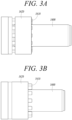
- FIGS. 3A and 3B are views illustrating the process of assembling a tie rod-locking nut according to the related art
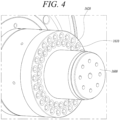
- FIG. 4 is a perspective view illustrating a tie rod-locking nut assembled on a tie rod according to the related art.
- a jack bolt 1610 is formed at an end of the tie rod 1600, and the tie rod-locking nut 1620 is fastened inserting the jack bolt 1610 into the tie-rod locking nut 1620.
- the tie rod-locking nut 1620 is able to provide a high tension force and tightening force to the tie rod 1600 as it is threaded onto the jack bolt 1610.
- the tie rod-locking nut 1620 may be loosened from the jack bolt 1610 by vibrations generated during operation.
- conventional gas turbines are not equipped with means to prevent the tie rod-locking nut 1620 from being loosened.
- the present invention discloses a tie rod-locking nut assembly capable of preventing the tie rod-locking nut from being loosened during operation of the gas turbine, and a gas turbine including the tie rod-locking nut.
- FIG. 5 is a perspective view illustrating a tie rod-locking nut assembly according to an embodiment of the present invention
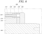
- FIG. 6 is a cross-sectional view illustrating the tie rod-locking nut assembly according to the embodiment of the present invention
- FIG. 7 is a perspective view illustrating a jack bolt-locking nut inserted between the tie rod-locking nut and the jack bolt
- FIG. 8 is a cross-sectional view of FIG. 7
- FIG. 9 is a perspective view illustrating the state of an anti-loosening washer being engaged in the configuration of FIG. 7
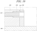
- FIG. 10 is a cross-sectional view of FIG. 9 .
- the tie rod-locking nut assembly 2000 includes a tie rod-locking nut 2100, a jack bolt-locking nut 2200, an anti-loosening washer 2300, and a locking plate 2400.
- a plurality of jack bolts 1610 are arranged.
- the jack bolts 1610 may be circularly arranged to form a circle around a central axis of the tie rod 1600.
- the circle formed by the plurality of jack bolts 1610 may be arranged in two concentric circles centered on the tie rod 1600.
- the plurality of jack bolts 1610 may be inserted in the rod-locking nut 2100 such that they form two concentric circles centered on the central axis of the tie rod 1600.
- the jack bolts 1610 may be coupled to the tie rod 1600.
- the jack bolts 1610 may axially protrude from a stepped portion formed in the tie rod 1600, as exemplarily shown in Fig. 3A .
- the direction in which the jack bolts 1610 are inserted in the rod-locking nut 2100 may be referred to as an upstream direction, which is parallel to the central axis of the tie rod 1600.
- the direction opposite to the upstream direction may be referred to as a downstream direction.
- the tie rod-locking nut 2100 is fastened by inserting the plurality of jack bolts 1610 formed at the end of the tie rod 1600 into the tie-rod locking nut 2100.
- the tie rod-locking nut 2100 has a plurality of jack bolt-insertion holes 2110 formed at locations corresponding to the locations in which the plurality of jack bolts 1610 are formed.
- the plurality of jack bolt-insertion holes 2110 may form a circle centered on the tie rod 1600, as in the plurality of jack bolts 1610.
- the plurality of jack bolt-insertion holes 2110 may be circularly arranged, being spaced apart from each other with regular intervals and having the tie rod 1600 at the center.
- the plurality of jack bolt-insertion holes 2110 may be arranged to form double concentric circles centered on the tie rod 1600.
- each of the plurality of jack bolt-insertion holes 2110 may be in a cylindrical shape.
- the plurality of jack bolt-insertion holes 2110 may be formed by being grooved toward the upstream direction from a downstream end surface of the tie rod-locking nut 2100.
- the jack bolt-insertion holes 2110 may open on a first axial end face of the tie rod-locking nut 2100.
- Each of the plurality of jack bolt-insertion holes 2110 may be in a cylindrical shape having an inner circumferential surface.
- the inner circumferential surface of the insertion hole 2110 may comprise a step, wherein an outer portion 2120 or downstream portion jack bolt-insertion holes 2110 extending between the first axial end face of the tie rod-locking nut 2100 and the step has a greater diameter than an inner portion of jack bolt-insertion hole 2110 extending from the step oppositely to the outer portion.
- an outer portion 2120 is formed at a downstream end portion or outer end portion of the jack bolt-insertion holes 2110. The outer end portion is adjacent to the first axial end face of the tie rod-locking nut 2100.
- the second diameter is larger than the first diameter.
- the first and second diameters may be constant.
- the cylindrical shape of the jack bolt-insertion hole 2110 includes a front part or inner part at relatively upstream and an end part or outer part 2120 at relatively downstream of the step, while the front part and the end part are concentric, the end part has a larger diameter than the front part.
- each jack bolt 1610 is inserted into one of the jack bolt-insertion holes 2110.
- the jack bolt 1610 is engaged with a thread formed on the inner surface of the first part of the jack bolt-insertion hole 2110 and there is formed a space between the jack bolt 1610 and the end part of the jack bolt-insertion hole 2110 (i.e., a space between the jack bolt 1610 and the stepped portion 2120).
- a jack bolt-locking nut 2200 is formed to have a shape of hollow pipe with both ends open, and is inserted between the tie rod-locking nut 2100 and the jack bolt 1610. In other words, the jack bolt-locking nut 2200 is inserted in the space between the jack bolt 1610 and the end part of the tie rod-locking nut 2110. When the jack bolt-locking nut 2200 engages with the jack bolt 1610, the jack bolt-locking nut may be inserted into a gap formed between the jack bolt 1610 and the outer portion 2120 formed at the end of the jack bolt-insertion hole 2110.
- the cross-section of the jack bolt-locking nut 2200 may be in a shape such that the outer circumference is a circular shape corresponding to the outer portion 2120 of the jack bolt-insertion hole 2110 and the inner circumference may be a polygonal shape corresponding to an outer surface of an end portion of the jack bolt 1610.
- the outer surface of the end portion of the jack bolt 1610 and the inner circumference of the jack bolt-locking nut 2200 may be formed to form fittingly engage.
- the jack bolt-locking nut 2200 may be formed with a length greater than a length of the outer portion 2120, such that when inserted into the gap, an downstream end of the jack bolt-locking nut 2200 may be exposed externally from the tie rod-locking nut 2100. In other words, when inserted into the gap, a downstream end of the jack bolt-locking nut 2200 may be exposed by protruding further downstream than the downstream end surface of the tie rod-locking nut 2100. Generally, when inserted into the gap, the jack bolt-locking nut 2200 may protrude from the first axial end face of the tie rod-locking nut 2100.
- the anti-loosening washer 2300 is formed to wrap around an outer circumferential surface of the jack bolt-locking nut 2200, especially the protruding portions of the jack bolt-locking nut 2200.
- the anti-loosening washer 2300 is in close contact with the tie rod-locking nut 2100.
- the area in which the jack bolt-locking nut 2200 and the anti-loosening washer 2300 contact may be caulked to prevent rotation of the jack bolt-locking nut 2200, thereby preventing the jack bolt-locking nut 2200 from being loosened.
- “Caulking” in this context may be understood as a process of sealing a gap or joint between the two facing surfaces of the jack bolt-locking nut 2200 and the anti-loosening washer 2300 using a material such as caulk.
- the anti-loosening washer 2300 is a circular plate member or a disk-shaped plate member having a plurality of insertion holes 2310 formed in positions corresponding to the plurality of jack bolt-locking nuts 2200.
- the diameter and the location of the insertion holes 2310 formed in the anti-loosening washer 2300 may be the same as the diameter and the location of the outer portions 2120 of the plurality of j ack bolt-insertion holes 2110 in the tie rod-locking nut 2100.
- an axial length of the anti-loosening washer 2300 may be the same with the length of the protruding portions of the jack bolt-locking nut 2200.
- the inner diameters of the insertion holes 2310 are formed to be sized to allow the jack bolt-locking nuts 2200 to be inserted.
- the plurality of insertion holes 2310 are arranged to form a circle centered on the tie rod 1600 as in the plurality of jack bolts 1610. According to an embodiment, the plurality of insertion holes 2310 may be arranged to form double centric circles centered on the tie rod 1600.
- a through-hole is formed at the center of the anti-loosening washer 2300 such that the tie rod 1600 passes therethrough.
- the anti-loosening washer 2300 may be provided with a thread on the through-hole so that it may be threaded onto the tie rod 1600.
- the outer diameter of the anti-loosening washer 2300 may be the same with the outer diameter of the tie rod-locking nut 2100.
- the locking plate 2400 is formed and arranged to cover the jack bolt-locking nut 2200 and the anti-loosening washer 2300 at their downstream ends.
- the locking plate 2400 is formed in the same shape as the anti-loosening washer 2300 except that the locking plate 2400 does not have insertion holes 2310 and that the locking plate 2400 may be thicker than the anti-loosening washer 2300 (i.e., longer axial length). That is, the locking plate 2400 is a circular plate member or a disk-shaped plate member of the same size (i.e., same outer diameters) as the anti-loosening washer 2300, and has a through-hole formed at the center such that the tie rod 1600 passes therethrough.
- a thread may be formed on an inner circumferential surface of the locking plate 2400 to engage with a thread formed on the outer circumferential surface of the tie rod 1600.
Landscapes
- Engineering & Computer Science (AREA)
- General Engineering & Computer Science (AREA)
- Mechanical Engineering (AREA)
- Chemical & Material Sciences (AREA)
- Combustion & Propulsion (AREA)
- Structures Of Non-Positive Displacement Pumps (AREA)
Abstract
Description
- The present application claims priority to
Korean Patent Application No. 10-2023-0012528, filed on January 31, 2023 - The present invention relates to a tie rod-locking nut assembly and a gas turbine including the same.
- A turbine is a mechanical device that obtains a rotational force by an impulsive force or reaction force using a flow of a compressible fluid such as steam or gas. A turbine may be a steam turbine using steam, or a gas turbine using a high temperature combustion gas.
- Among them, the gas turbine is mainly composed of a compressor, a combustor, and a turbine. The compressor is provided with an air inlet for introducing air, and a plurality of compressor vanes and compressor blades, which are alternately arranged in a compressor housing.
- The combustor supplies fuel to the compressed air compressed in the compressor and ignites a fuel-air mixture with a burner to produce a high temperature and high pressure combustion gas.
- The turbine has a plurality of turbine vanes and turbine blades disposed alternately in a turbine casing. Further, a rotor is arranged to pass through the center of the compressor, the combustor, the turbine and an exhaust chamber.
- Both ends of the rotor are rotatably supported by bearings. A plurality of disks is fixed to the rotor so that the respective blades are connected. A drive shaft such as a generator is connected to an end of the exhaust chamber.
- Since these gas turbines have no reciprocating mechanism such as a piston found in a 4-stroke engine, and consequently have no frictional parts like piston-cylinder, they have several advantages. These include minimal consumption of lubricating oil, a significant reduction in amplitude, which is a characteristic of a reciprocating machine, and the ability to operate at high speed operation.
- Briefly describing the operation of the gas turbine, the compressed air compressed in the compressor is mixed with fuel and combusted to produce a high-temperature combustion gas in the combustor, which is then injected toward the turbine. The injected combustion gas passes through the turbine vanes and the turbine blades to generate a rotational force, which causes the rotor to rotate.
- The foregoing is intended merely to aid in the understanding of the background of the present invention, and is not intended to mean that the present invention falls within the purview of the related art that is already known to those skilled in the art.
- Accordingly, the present invention has been made keeping in mind the above problems occurring in the related art, and an objective of the present invention is to provide a tie rod-locking nut assembly capable of preventing a tie rod-locking nut from being loosened during operation of a gas turbine, and a gas turbine including the same.
- To this end, the present invention provides a tie rod-locking nut assembly in accordance with
claim 1 and a gas turbine in accordance with claim 10. Advantageous embodiments are subject to the dependent claims and the following description, referring to the drawings. - In a first aspect of the present invention, a tie rod-locking nut assembly includes: a tie rod-locking nut engaged with or fastened to a jack bolt, e.g., in that the jack bolt is inserted or introduced into the tie rod-locking nut; a jack bolt-locking nut inserted between the tie rod-locking nut and the jack bolt; an anti-loosening washer formed to wrap around an outer circumferential surface of the jack bolt-locking nut to prevent loosening of the jack bolt-locking nut; and a locking plate formed to cover the anti-loosening washer and engaging with an outer circumferential surface of the tie rod.
- It is one of the ideas of the present invention to prevent loosening of the jack bolt-locking nut by an anti-loosening washer which engages outer circumferential surface of the jack bolt-locking nut. The anti-loosening washer may be configured for being coupled to the tie rod and may engaged with the jack bolt-locking nut such that rotation of the jack bolt-locking nut is prevented.
- In some embodiments, the tie rod-locking nut may have a jack bolt-insertion hole formed at a position corresponding to a position in which the jack bolt is formed, and the jack bolt-insertion hole has a stepped portion formed at an end of the jack bolt-insertion hole.
- In some embodiments, the jack bolt-locking nut has a shape of hollow pipe with both ends open and may be inserted into a gap formed between the stepped portion and the jack bolt during engagement with the jack bolt. Generally, the jack bolt-insertion hole may include a step dividing the jack bolt-insertion hole into an outer portion formed at an end of the jack bolt-insertion hole and an inner portion formed on an opposite side of the step, wherein the outer portion has a greater diameter than the inner portion. The outer portion, herein, may also be referred to as stepped portion.
- In some embodiments, the jack bolt-locking nut may be formed with a length greater than the stepped portion such that, when inserted into the gap, a distal end thereof is exposed externally from the tie rod-locking nut, wherein the jack bolt-locking nut is in a shape such that a cross-section of the jack bolt-locking nut has an outer circumference in a circular shape corresponding to the stepped portion and has an inner circumference in a preferably polygonal shape corresponding to the jack bolt.
- In some embodiments, a contact area between the jack bolt-locking nut and the anti-loosening washer may be caulked.
- In some embodiments, the anti-loosening washer may be a circular plate member having a plurality of insertion holes formed in positions corresponding to the plurality of jack bolt-locking nuts.
- In some embodiments, an inner circumferential surface of the locking plate may be threaded to engage with the outer circumferential surface of the tie rod.
- In a second aspect of the present invention, a gas turbine includes: a compressor suctioning and compressing external air and having a plurality of compressor rotor disks; a combustor mixing fuel with compressed air and combusting an air-fuel mixture; a turbine section having a plurality of turbine blades mounted on a plurality of turbine rotor disks so that the turbine blades is rotated by the combustion gases discharged from the combustor; and a tie rod having one end engaged with a most upstream-side one of the compressor rotor disks and the other end engaged with a tie rod-locking nut assembly, the tie rod-locking nut assembly including: a tie rod-locking nut threaded onto a jack bolt formed; a jack bolt-locking nut inserted between the tie rod-locking nut and the jack bolt; an anti-loosening washer formed to wrap around an outer circumferential surface of the jack bolt-locking nut to prevent loosening of the jack bolt-locking nut; and a locking plate formed to cover the anti-loosening washer and engaging with an outer circumferential surface of the tie rod. The tie rod-locking nut assembly, thus, may be the tie rod-locking nut assembly of the first aspect of the invention.
- In some embodiments, the tie rod-locking nut may have a jack bolt-insertion hole formed at a position corresponding to a position in which the jack bolt is formed, and the jack bolt-insertion hole has a stepped portion formed at an end of the jack bolt-insertion hole.
- In some embodiments, the jack bolt-locking nut may have a shape of hollow pipe with both ends open and may be inserted into a gap formed between the stepped portion and the jack bolt during engagement with the jack bolt.
- In some embodiments, the jack bolt-locking nut may be formed with a length greater than the stepped portion such that, when inserted into the gap, a distal end thereof is exposed externally from the tie rod-locking nut, wherein the jack bolt-locking nut is in a shape such that a cross-section of the jack bolt-locking nut has an outer circumference in a circular shape corresponding to the stepped portion and has an inner circumference in a polygonal shape corresponding to the jack bolt.
- In some embodiments, a contact area between the jack bolt-locking nut and the anti-loosening washer may be caulked.
- In some embodiments, the anti-loosening washer may be a circular plate member having a plurality of insertion holes formed in positions corresponding to the plurality of jack bolt-locking nuts.
- In some embodiments, an inner circumferential surface of the locking plate may be threaded to engage with the outer circumferential surface of the tie rod.
- Specific details of other implementations of various aspects of the present invention are included in the following detailed description.
- According to embodiments of the present invention, it is possible to prevent the tie rod-locking nut from being loosened from the jack bolt due to vibration generated during operation of the gas turbine, thereby improving the operational stability of the gas turbine.
-
-
FIG. 1 is a partially cut-away perspective view of a gas turbine according to an embodiment of the present invention; -
FIG. 2 is a cross-sectional view illustrating a schematic structure of a gas turbine according to an embodiment of the present invention; -
FIGS. 3A and 3B are views illustrating the process of assembling a tie rod-locking nut according to the related art; -
FIG. 4 is a perspective view illustrating a tie rod-locking nut assembled on a tie rod according to the related art; -
FIG. 5 is a perspective view illustrating a tie rod-locking nut assembly according to an embodiment of the present invention; -
FIG. 6 is a cross-sectional view illustrating the tie rod-locking nut assembly according to the embodiment of the present invention; -
FIG. 7 is a perspective view illustrating a jack bolt-locking nut inserted between the tie rod-locking nut and the jack bolt; -
FIG. 8 is a cross-sectional view ofFIG. 7 ; -
FIG. 9 is a perspective view illustrating the state of an anti-loosening washer being engaged in the configuration ofFIG. 7 ; and -
FIG. 10 is a cross-sectional view ofFIG. 9 . - Hereinafter, exemplary embodiments of the present invention will be described in detail with reference to the accompanying drawings. However, it should be noted that the present invention is not limited thereto.
- Terms used herein are used to merely describe specific embodiments, and are not intended to limit the present invention. As used herein, an element expressed as a singular form includes a plurality of elements, unless the context clearly indicates otherwise. Further, it will be understood that the term "comprising" or "including" specifies the presence of stated features, numbers, steps, operations, elements, parts, or combinations thereof, but does not preclude the presence or addition of one or more other features, numbers, steps, operations, elements, parts, or combinations thereof.
- Hereinafter, preferred embodiments of the present invention will be described in detail with reference to the accompanying drawings. It is noted that like elements are denoted in the drawings by like reference symbols as whenever possible. Further, the detailed description of known functions and configurations that may obscure the gist of the present invention will be omitted. For the same reason, some of the elements in the drawings are exaggerated, omitted, or schematically illustrated.
-
FIG. 1 is a partially cut-away perspective view of a gas turbine according to an embodiment of the present invention, andFIG. 2 is a cross-sectional view illustrating a schematic structure of a gas turbine according to an embodiment of the present invention. - As illustrated in
FIG. 1 , agas turbine 1000 according to an embodiment of the present invention includes acompressor 1100, acombustor 1200, and aturbine 1300. Thecompressor 1100 includes a plurality ofcompressor blades 1110 radially installed. Thecompressor 1100 rotates thecompressor blade 1110 so that air flows while being compressed by the rotation of thecompressor blade 1110. The size and installation angle of theblade 1110 may vary depending on the installation location. In one embodiment, thecompressor 1100 is connected directly or indirectly to theturbine 1300, and receives a portion of the power generated from theturbine 1300 to rotate thecompressor blade 1110. - Air compressed by the
compressor 1100 flows to thecombustor 1200. Thecombustor 1200 includes a plurality ofcombustion chambers 1210 and afuel nozzle module 1220 arranged in an annular shape. - The
gas turbine 1000 includes ahousing 1010 and adiffuser 1400 which is disposed on a rear side of thehousing 1010 and through which a combustion gas passing through a turbine is discharged. Acombustor 1200 is disposed in front of thediffuser 1400 so as to receive and burn compressed air. - Referring to the flow direction of the air, a
compressor section 1100 is located on the upstream side of thehousing 1010, and aturbine section 1300 is located on the downstream side of the housing. Atorque tube 1500 is disposed as a torque transmission member between thecompressor section 1100 and theturbine section 1300 to transmit the rotational torque generated in the turbine section to the compressor section. - The
compressor section 1100 is provided with a plurality (for example, 14) ofcompressor rotor disks 1120, which are fastened by atie rod 1600 to prevent axial separation thereof. - Specifically, the
compressor rotor disks 1120 are axially arranged, wherein thetie rod 1600 constituting a rotary shaft passes through substantially central portions of thecompressor rotor disks 1120. Here, the neighboringcompressor rotor disks 1120 are disposed so that opposed surfaces thereof are pressed against each other by an axial force applied through thetie rod 1600, so that the neighboring compressor rotor disks do not rotate relative to each other. - A plurality of
compressor blades 1110 are radially coupled to an outer circumferential surface of eachcompressor rotor disk 1120. Each of thecompressor blades 1110 may have a dovetail part 1112 which is fastened to thecompressor rotor disk 1120. The invention is not limited to a dovetail part 1112 but thecompressor blades 1110 may comprise, generally, a coupling member which has a cross-section corresponding to a coupling groove formed in thecompressor rotor disk 1120. - Compressor vanes (not shown) fixed to the housing are respectively positioned between the
rotor disks 1120. Unlike the compressor rotor disks, the compressor vanes are fixed to the housing and do not rotate. The compressor vane serves to align a flow of compressed air that has passed through thecompressor blades 1110 of thecompressor rotor disk 1120 and guide the air to thecompressor blades 1110 of therotor disk 1120 located on the downstream side. - The fastening method of the dovetail part 1112 includes a tangential type and an axial type. These may be chosen according to the required structure of the commercial gas turbine, and may have a generally known dovetail or fir-tree shape. In some cases, it is possible to fasten the blades to the rotor disk by using other fasteners such as keys or bolts in addition to the fastening shape.
- The
tie rod 1600 is arranged to pass through the center of thecompressor rotor disks 1120 andturbine rotor disks 1320 such that one end thereof is engaged with an engaging member, such as the compressor rotor disk located on the most upstream side, and the other end thereof is engaged with a tie rod-lockingnut assembly 2000. Thetie rod 1600 may be composed of a single tie rod or a plurality of tie rods. Generally, thetie rod 1600 extends longitudinally between a first end and a second end. The tie rod-lockingnut assembly 2000 according to the present invention will be described later with reference toFIGS. 5 to 10 . - The shape of the
tie rod 1600 is not limited to that shown inFIG. 2 , but may have a variety of structures depending on the gas turbine. That is, as shown in the drawing, one tie rod may have a shape passing through a central portion of the rotor disk, a plurality of tie rods may be arranged in a circumferential manner, or a combination thereof may be used. Generally, the engagement member, e.g., the compressor rotor disk located on the most upstream side, and the tie rod-lockingnut assembly 2000 are engaged with opposite ends of thetie rod 1600 and, together, apply an axial force to thecompressor rotor disks 1120 andturbine rotor disks 1320 so that they are clamped axially between the engagement member and the tie rod-lockingnut assembly 2000. - Although not shown, the compressor of the gas turbine may be provided with a vane serving as a guide element at the next position of the diffuser in order to adjust a flow angle of a pressurized fluid entering a combustor inlet to a designed flow angle. The vane is referred to as a deswirler.
- The
combustor 1200 mixes the introduced compressed air with fuel and combusts the air-fuel mixture to produce a high-temperature and high-pressure combustion gas. With an isobaric combustion process in the compressor, the temperature of the combustion gas is increased to the heat resistance limit that the combustor and the turbine components can withstand. - The combustor consists of a plurality of combustors, which is arranged in the housing formed in a cell shape, and includes a burner having a fuel injection nozzle and the like, a combustor liner forming a combustion chamber, and a transition piece as a connection between the combustor and the turbine, thereby constituting a combustion system of a gas turbine.
- Specifically, the combustor liner provides a combustion space in which the fuel injected by the fuel nozzle is mixed with the compressed air of the compressor and the fuel-air mixture is combusted. Such a liner may include a flame canister providing a combustion space in which the fuel-air mixture is combusted, and a flow sleeve forming an annular space surrounding the flame canister. A fuel nozzle is coupled to the front end of the liner, and an igniter plug is coupled to the side wall of the liner.
- On the other hand, a transition piece is connected to a rear end of the liner so as to transmit the combustion gas combusted by the igniter plug to the turbine side. An outer wall of the transition piece is cooled by the compressed air supplied from the compressor so as to prevent thermal breakage due to the high temperature combustion gas.
- To this end, the transition piece is provided with cooling holes through which compressed air is injected into and cools the inside of the transition piece and flows towards the liner.
- The air that has cooled the transition piece flows into the annular space of the liner and compressed air is supplied as a cooling air to the outer wall of the liner from the outside of the flow sleeve through cooling holes provided in the flow sleeve so that both air flows may collide with each other.
- In the meantime, the high-temperature and high-pressure combustion gas from the combustor is supplied to the
turbine 1300. The supplied high-temperature and high-pressure combustion gas expands and collides with the rotating blades of the turbine, generating a reaction force that imparts a rotational torque. This torque is subsequently transferred to the compressor via thetorque tube 1500. Here, any surplus power needed to drive the compressor is used to drive a generator or similar equipment. - The
turbine 1300 is basically similar in structure to the compressor. That is, theturbine 1300 is also provided with a plurality ofturbine rotor disks 1320 similar to the compressor rotor disks of the compressor. Thus, theturbine rotor disk 1320 also includes a plurality ofturbine blades 1310 disposed radially. Theturbine blade 1310 may also be coupled to theturbine rotor disk 1320 in a dovetail coupling manner, for example. That is, theturbine blades 1310 may comprise, generally, a coupling member which has a cross-section corresponding to a coupling groove formed in theturbine rotor disk 1320. - Between the
turbine blades 1310, a turbine vane (not shown) fixed to aturbine casing 1350 is provided to guide a flow direction of the combustion gas passing through the turbine blades. -
FIGS. 3A and 3B are views illustrating the process of assembling a tie rod-locking nut according to the related art, andFIG. 4 is a perspective view illustrating a tie rod-locking nut assembled on a tie rod according to the related art. - Referring to
FIGS. 3A, 3B , and4 , ajack bolt 1610 is formed at an end of thetie rod 1600, and the tie rod-lockingnut 1620 is fastened inserting thejack bolt 1610 into the tie-rod locking nut 1620. The tie rod-lockingnut 1620 is able to provide a high tension force and tightening force to thetie rod 1600 as it is threaded onto thejack bolt 1610. - Large-scale gas turbines rotate at approximately 3600 RPM and are exposed to a variety of high-temperature/high-pressure environments. In particular, the tie rod-locking
nut 1620 may be loosened from thejack bolt 1610 by vibrations generated during operation. However, conventional gas turbines are not equipped with means to prevent the tie rod-lockingnut 1620 from being loosened. Accordingly, the present invention discloses a tie rod-locking nut assembly capable of preventing the tie rod-locking nut from being loosened during operation of the gas turbine, and a gas turbine including the tie rod-locking nut. -
FIG. 5 is a perspective view illustrating a tie rod-locking nut assembly according to an embodiment of the present invention,FIG. 6 is a cross-sectional view illustrating the tie rod-locking nut assembly according to the embodiment of the present invention,FIG. 7 is a perspective view illustrating a jack bolt-locking nut inserted between the tie rod-locking nut and the jack bolt,FIG. 8 is a cross-sectional view ofFIG. 7 ,FIG. 9 is a perspective view illustrating the state of an anti-loosening washer being engaged in the configuration ofFIG. 7 , andFIG. 10 is a cross-sectional view ofFIG. 9 . - Referring to
FIGS. 5 to 10 , the tie rod-lockingnut assembly 2000 includes a tie rod-lockingnut 2100, a jack bolt-lockingnut 2200, ananti-loosening washer 2300, and alocking plate 2400. - At an end of the
tie rod 1600, a plurality ofjack bolts 1610 are arranged. For example, thejack bolts 1610 may be circularly arranged to form a circle around a central axis of thetie rod 1600. The circle formed by the plurality ofjack bolts 1610 may be arranged in two concentric circles centered on thetie rod 1600. In other words, the plurality ofjack bolts 1610 may be inserted in the rod-lockingnut 2100 such that they form two concentric circles centered on the central axis of thetie rod 1600. Thejack bolts 1610 may be coupled to thetie rod 1600. In particular, thejack bolts 1610 may axially protrude from a stepped portion formed in thetie rod 1600, as exemplarily shown inFig. 3A . - The direction in which the
jack bolts 1610 are inserted in the rod-lockingnut 2100 may be referred to as an upstream direction, which is parallel to the central axis of thetie rod 1600. The direction opposite to the upstream direction may be referred to as a downstream direction. - The tie rod-locking
nut 2100 is fastened by inserting the plurality ofjack bolts 1610 formed at the end of thetie rod 1600 into the tie-rod locking nut 2100. The tie rod-lockingnut 2100 has a plurality of jack bolt-insertion holes 2110 formed at locations corresponding to the locations in which the plurality ofjack bolts 1610 are formed. For example, the plurality of jack bolt-insertion holes 2110 may form a circle centered on thetie rod 1600, as in the plurality ofjack bolts 1610. In other words, the plurality of jack bolt-insertion holes 2110 may be circularly arranged, being spaced apart from each other with regular intervals and having thetie rod 1600 at the center. According to an embodiment, the plurality of jack bolt-insertion holes 2110 may be arranged to form double concentric circles centered on thetie rod 1600. - According to an embodiment, each of the plurality of jack bolt-
insertion holes 2110 may be in a cylindrical shape. The plurality of jack bolt-insertion holes 2110 may be formed by being grooved toward the upstream direction from a downstream end surface of the tie rod-lockingnut 2100. In other words, the jack bolt-insertion holes 2110 may open on a first axial end face of the tie rod-lockingnut 2100. Each of the plurality of jack bolt-insertion holes 2110 may be in a cylindrical shape having an inner circumferential surface. The inner circumferential surface of theinsertion hole 2110 may comprise a step, wherein anouter portion 2120 or downstream portion jack bolt-insertion holes 2110 extending between the first axial end face of the tie rod-lockingnut 2100 and the step has a greater diameter than an inner portion of jack bolt-insertion hole 2110 extending from the step oppositely to the outer portion. Thus, generally, anouter portion 2120 is formed at a downstream end portion or outer end portion of the jack bolt-insertion holes 2110. The outer end portion is adjacent to the first axial end face of the tie rod-lockingnut 2100. When a diameter of the jack bolt-insertion hole 2110 measured at an upstream side of the step is defined as a first diameter, and a diameter of the jack bolt-insertion hole 2110 measured on a downstream side of the step is defined as a second diameter, the second diameter is larger than the first diameter. The first and second diameters may be constant. In other words, the cylindrical shape of the jack bolt-insertion hole 2110 includes a front part or inner part at relatively upstream and an end part orouter part 2120 at relatively downstream of the step, while the front part and the end part are concentric, the end part has a larger diameter than the front part. - Generally, each
jack bolt 1610 is inserted into one of the jack bolt-insertion holes 2110. When thejack bolt 1610 is inserted into the jack bolt-insertion hole 2110, thejack bolt 1610 is engaged with a thread formed on the inner surface of the first part of the jack bolt-insertion hole 2110 and there is formed a space between thejack bolt 1610 and the end part of the jack bolt-insertion hole 2110 (i.e., a space between thejack bolt 1610 and the stepped portion 2120). - A jack bolt-locking
nut 2200 is formed to have a shape of hollow pipe with both ends open, and is inserted between the tie rod-lockingnut 2100 and thejack bolt 1610. In other words, the jack bolt-lockingnut 2200 is inserted in the space between thejack bolt 1610 and the end part of the tie rod-lockingnut 2110. When the jack bolt-lockingnut 2200 engages with thejack bolt 1610, the jack bolt-locking nut may be inserted into a gap formed between thejack bolt 1610 and theouter portion 2120 formed at the end of the jack bolt-insertion hole 2110. The cross-section of the jack bolt-lockingnut 2200 may be in a shape such that the outer circumference is a circular shape corresponding to theouter portion 2120 of the jack bolt-insertion hole 2110 and the inner circumference may be a polygonal shape corresponding to an outer surface of an end portion of thejack bolt 1610. Generally, the outer surface of the end portion of thejack bolt 1610 and the inner circumference of the jack bolt-lockingnut 2200 may be formed to form fittingly engage. The jack bolt-lockingnut 2200 may be formed with a length greater than a length of theouter portion 2120, such that when inserted into the gap, an downstream end of the jack bolt-lockingnut 2200 may be exposed externally from the tie rod-lockingnut 2100. In other words, when inserted into the gap, a downstream end of the jack bolt-lockingnut 2200 may be exposed by protruding further downstream than the downstream end surface of the tie rod-lockingnut 2100. Generally, when inserted into the gap, the jack bolt-lockingnut 2200 may protrude from the first axial end face of the tie rod-lockingnut 2100. - The
anti-loosening washer 2300 is formed to wrap around an outer circumferential surface of the jack bolt-lockingnut 2200, especially the protruding portions of the jack bolt-lockingnut 2200. Theanti-loosening washer 2300 is in close contact with the tie rod-lockingnut 2100. The area in which the jack bolt-lockingnut 2200 and theanti-loosening washer 2300 contact may be caulked to prevent rotation of the jack bolt-lockingnut 2200, thereby preventing the jack bolt-lockingnut 2200 from being loosened. "Caulking" in this context may be understood as a process of sealing a gap or joint between the two facing surfaces of the jack bolt-lockingnut 2200 and theanti-loosening washer 2300 using a material such as caulk. Theanti-loosening washer 2300 is a circular plate member or a disk-shaped plate member having a plurality ofinsertion holes 2310 formed in positions corresponding to the plurality of jack bolt-locking nuts 2200. The diameter and the location of the insertion holes 2310 formed in theanti-loosening washer 2300 may be the same as the diameter and the location of theouter portions 2120 of the plurality of j ack bolt-insertion holes 2110 in the tie rod-lockingnut 2100. The thickness, in other words, an axial length of theanti-loosening washer 2300 may be the same with the length of the protruding portions of the jack bolt-lockingnut 2200. The inner diameters of theinsertion holes 2310 are formed to be sized to allow the jack bolt-lockingnuts 2200 to be inserted. The plurality ofinsertion holes 2310 are arranged to form a circle centered on thetie rod 1600 as in the plurality ofjack bolts 1610. According to an embodiment, the plurality ofinsertion holes 2310 may be arranged to form double centric circles centered on thetie rod 1600. A through-hole is formed at the center of theanti-loosening washer 2300 such that thetie rod 1600 passes therethrough. For example, theanti-loosening washer 2300 may be provided with a thread on the through-hole so that it may be threaded onto thetie rod 1600. The outer diameter of theanti-loosening washer 2300 may be the same with the outer diameter of the tie rod-lockingnut 2100. - The
locking plate 2400 is formed and arranged to cover the jack bolt-lockingnut 2200 and theanti-loosening washer 2300 at their downstream ends. Thelocking plate 2400 is formed in the same shape as theanti-loosening washer 2300 except that thelocking plate 2400 does not haveinsertion holes 2310 and that thelocking plate 2400 may be thicker than the anti-loosening washer 2300 (i.e., longer axial length). That is, thelocking plate 2400 is a circular plate member or a disk-shaped plate member of the same size (i.e., same outer diameters) as theanti-loosening washer 2300, and has a through-hole formed at the center such that thetie rod 1600 passes therethrough. A thread may be formed on an inner circumferential surface of thelocking plate 2400 to engage with a thread formed on the outer circumferential surface of thetie rod 1600. - According to embodiments of the present invention, it is possible to prevent the tie rod-locking nut from being loosened from the jack bolt due to vibration generated during operation of the gas turbine, thereby improving the operational stability of the gas turbine.
- While the embodiments of the present invention have been described, it will be apparent to those skilled in the art that various modifications and variations can be made in the present invention through addition, change, omission, or substitution of components without departing from the scope of the invention as set forth in the appended claims.
Claims (10)
- A tie rod-locking nut assembly (2000) comprising:a tie rod-locking nut (2100) engaged with a jack bolt (1610);a jack bolt-locking nut (2200) inserted between the tie rod-locking nut (2100) and the jack bolt (1610);an anti-loosening washer (2300) formed to wrap around an outer circumferential surface of the jack bolt-locking nut (2200) to prevent loosening of the jack bolt-locking nut (2200); anda locking plate (2400) formed to cover the anti-loosening washer (2300) and engaging with an outer circumferential surface of the tie rod (1600).
- The tie rod-locking nut assembly (2000) of claim 1, wherein the tie rod-locking nut (2100) has a jack bolt-insertion hole (2110) formed at a position corresponding to a position in which the jack bolt (1600) is formed, and the jack bolt-insertion hole (2110) includes a step dividing the jack bolt-insertion hole (2110) into an outer portion (2120) formed at an end of the jack bolt-insertion hole (2110) and an inner portion formed on an opposite side of the step, wherein the outer portion has a greater diameter than the inner portion.
- The tie rod-locking nut assembly (2000) of claim 2, wherein the jack bolt-locking nut (2200) has a shape of a hollow pipe with both ends open and is inserted into a gap formed between the outer portion (2120) and the jack bolt (1610) when being engaged with the jack bolt (1610).
- The tie rod-locking nut assembly (2000) of claim 3, wherein the jack bolt-locking nut (2200) is formed with a length greater than a length of the outer portion (2120) such that, when inserted into the gap, a distal end thereof is exposed externally from the tie rod-locking nut (2100),
wherein the jack bolt-locking nut (2200) is in a shape such that a cross-section of the jack bolt-locking nut (2200) has an outer circumference in a circular shape corresponding to the outer portion (2120) of the jack bolt-insertion hole (2110) and has an inner circumference in a shape corresponding to the jack bolt (1610). - The tie rod-locking nut assembly (2000) of claim 4, wherein the inner circumference of the of the jack bolt-locking nut (2200) has a polygonal shape corresponding to the jack bolt (1610).
- The tie rod-locking nut assembly (2000) of any one of the preceding claims, wherein a contact area between the jack bolt-locking nut (2200) and the anti-loosening washer (2300) is caulked.
- The tie rod-locking nut assembly (2000) of any one of the preceding claims, wherein the anti-loosening washer (2300) is a circular plate member having an insertion hole (2310) formed in a position corresponding to the jack bolt-locking nut (2200).
- The tie rod-locking nut assembly (2000) of claim 7 insofar as being dependent upon claim 4, wherein the distal end of the jack bolt-locking nut (2200) extends into the insertion hole (2310) of the anti-loosening washer (2300).
- The tie rod-locking nut assembly (2000) of any one of the preceding claims, wherein an inner circumferential surface of the locking plate (2400) comprises a thread configured to engage with the outer circumferential surface of the tie rod (1600).
- A gas turbine (1000) comprising:a compressor (1100) configured to suction and compress external air and having a plurality of compressor rotor disks (1120);a combustor (1200) configured to mix fuel with compressed air and to combust an air-fuel mixture;a turbine section (1300) having a plurality of turbine rotor disks (1320) with a plurality of turbine blades (1310) mounted on each turbine rotor disk (1320), so that the turbine blades (1310) are rotatable together with the turbine rotor disks (1320) by the combustion gases discharged from the combustor (1200); anda tie rod (1600) having one end engaged with a most upstream-side one of the compressor rotor disks (1120) and the other end engaged with a tie rod-locking nut assembly (2000) according to any one of the preceding claims.
Applications Claiming Priority (1)
| Application Number | Priority Date | Filing Date | Title |
|---|---|---|---|
| KR1020230012528A KR102760691B1 (en) | 2023-01-31 | 2023-01-31 | Tie rod fixing nut assembly and gas turbine comprising it |
Publications (2)
| Publication Number | Publication Date |
|---|---|
| EP4411106A1 true EP4411106A1 (en) | 2024-08-07 |
| EP4411106B1 EP4411106B1 (en) | 2025-05-28 |
Family
ID=89771862
Family Applications (1)
| Application Number | Title | Priority Date | Filing Date |
|---|---|---|---|
| EP24154668.8A Active EP4411106B1 (en) | 2023-01-31 | 2024-01-30 | Tie rod-locking nut assembly and gas turbine including same |
Country Status (3)
| Country | Link |
|---|---|
| US (1) | US12442300B2 (en) |
| EP (1) | EP4411106B1 (en) |
| KR (1) | KR102760691B1 (en) |
Citations (4)
| Publication number | Priority date | Publication date | Assignee | Title |
|---|---|---|---|---|
| US20180187711A1 (en) * | 2017-01-04 | 2018-07-05 | General Electric Company | Locking nut and bolt assemblies for reducing windage in the vicinity of a high pressure flow region of a gas turbine engine |
| CN210565555U (en) * | 2019-06-21 | 2020-05-19 | 江苏华宏科技股份有限公司 | Large-scale pull rod fixing device |
| CN114810997A (en) * | 2022-04-20 | 2022-07-29 | 新奥能源动力科技(上海)有限公司 | Locking device and rotating mechanical equipment |
| KR20230012528A (en) | 2020-05-15 | 2023-01-26 | 퍼듀 리서치 파운데이션 | Compounds for SARS treatment |
Family Cites Families (27)
| Publication number | Priority date | Publication date | Assignee | Title |
|---|---|---|---|---|
| US3070348A (en) * | 1960-07-25 | 1962-12-25 | Gen Motors Corp | Composite rotor |
| US3618994A (en) * | 1969-05-14 | 1971-11-09 | Loopco Industries | Arbor nut |
| US4540199A (en) * | 1982-09-01 | 1985-09-10 | Neill David C | Jack bolt assembly |
| US4671324A (en) * | 1982-09-01 | 1987-06-09 | Neill David C | Jack bolt assembly |
| US4622730A (en) * | 1984-03-30 | 1986-11-18 | Rolf Steinbock | Apparatus to mechanically stress a bolt-type fastener |
| US5069587A (en) * | 1990-06-13 | 1991-12-03 | Dresser Industries, Inc. | Securing nut apparatus |
| US5257905A (en) * | 1992-05-08 | 1993-11-02 | Westinghouse Electric Corp. | Rotor coupling anti-windage apparatus |
| US5735655A (en) * | 1997-04-07 | 1998-04-07 | The Defiance Stamping Company | Lock nut assembly for vehicle axles |
| JPH11117340A (en) | 1997-10-15 | 1999-04-27 | Fukuhara Imono Seisakusho:Kk | Clamping device and locking tool of bolt for jack in sliding lifting-lowering type manhole-cover receiving frame |
| US6784597B1 (en) | 2003-04-15 | 2004-08-31 | General Electric Company | Self-locking nut for stud shaft and stacked wheel assembly for the rotor of a rotary machine |
| US7470115B2 (en) * | 2004-07-13 | 2008-12-30 | Honeywell International Inc. | Outer diameter nut piloting for improved rotor balance |
| JP4562500B2 (en) | 2004-11-22 | 2010-10-13 | 中国電力株式会社 | Guide jig for checking per valve seat seat |
| WO2014062208A1 (en) | 2012-10-02 | 2014-04-24 | Borgwarner Inc. | Reduction of turbocharger core unbalance with balance washer |
| EP2837775B1 (en) | 2013-08-15 | 2016-03-30 | ALSTOM Technology Ltd | Fixation device for turbine and method for applying fixation |
| JP5989615B2 (en) | 2013-08-26 | 2016-09-07 | 株式会社日立製作所 | Bolt fastening structure and turbomachine using the same |
| DE102014219643A1 (en) * | 2014-05-12 | 2015-11-12 | Siemens Aktiengesellschaft | Annular clamping nut for a tie rod |
| DE102015218428A1 (en) * | 2014-10-03 | 2016-04-07 | Borgwarner Inc., Patent Department | DEVICES AND METHOD FOR ADJUSTING THE BALANCE OF THE ROTATION ARRANGEMENT OF A TURBOCHARGER |
| KR101834647B1 (en) | 2016-07-07 | 2018-04-13 | 두산중공업 주식회사 | Disk assembly and a turbine using the same |
| KR101943749B1 (en) * | 2017-09-06 | 2019-01-29 | 한전케이피에스 주식회사 | Fastening device for a high-pressure turbine case |
| US10975772B2 (en) * | 2019-02-07 | 2021-04-13 | Hamilton Sundstrand Corporation | Starter locking assemblies and methods |
| CN110374692B (en) | 2019-07-18 | 2022-05-13 | 北京动力机械研究所 | Integrated rotor structure of radial turbine power generation system |
| JP2021060064A (en) * | 2019-10-04 | 2021-04-15 | 株式会社マルナカ | Washer, nut and member connecting structure |
| KR102268979B1 (en) | 2020-01-16 | 2021-06-24 | 두산중공업 주식회사 | Bolt-NutAssembly Structure, manufacturing method of nut, rotor assembly with bolt-nut assembly structure and gas turbine including the same |
| KR102294821B1 (en) | 2020-01-16 | 2021-08-27 | 두산중공업 주식회사 | Bolt-NutAssembly Structure, manufacturing method of nut, rotor assembly with bolt-nut assembly structure and gas turbine including the same |
| KR102325100B1 (en) | 2020-05-13 | 2021-11-10 | 두산중공업 주식회사 | Disc pressing device, and gas turbine including the same |
| KR102367002B1 (en) * | 2020-08-28 | 2022-02-23 | 두산중공업 주식회사 | Tensioning assembling structure of tie rod and gas turbine comprising the same and Tensioning assembling method of tie rod |
| US12331651B2 (en) * | 2023-06-26 | 2025-06-17 | Pratt & Whitney Canada Corp. | Internal retaining ring arrangement for a rotor assembly |
-
2023
- 2023-01-31 KR KR1020230012528A patent/KR102760691B1/en active Active
- 2023-11-22 US US18/517,568 patent/US12442300B2/en active Active
-
2024
- 2024-01-30 EP EP24154668.8A patent/EP4411106B1/en active Active
Patent Citations (4)
| Publication number | Priority date | Publication date | Assignee | Title |
|---|---|---|---|---|
| US20180187711A1 (en) * | 2017-01-04 | 2018-07-05 | General Electric Company | Locking nut and bolt assemblies for reducing windage in the vicinity of a high pressure flow region of a gas turbine engine |
| CN210565555U (en) * | 2019-06-21 | 2020-05-19 | 江苏华宏科技股份有限公司 | Large-scale pull rod fixing device |
| KR20230012528A (en) | 2020-05-15 | 2023-01-26 | 퍼듀 리서치 파운데이션 | Compounds for SARS treatment |
| CN114810997A (en) * | 2022-04-20 | 2022-07-29 | 新奥能源动力科技(上海)有限公司 | Locking device and rotating mechanical equipment |
Also Published As
| Publication number | Publication date |
|---|---|
| KR20240120129A (en) | 2024-08-07 |
| KR102760691B1 (en) | 2025-01-24 |
| EP4411106B1 (en) | 2025-05-28 |
| US12442300B2 (en) | 2025-10-14 |
| US20240254880A1 (en) | 2024-08-01 |
Similar Documents
| Publication | Publication Date | Title |
|---|---|---|
| US11053805B2 (en) | Vane ring assembly, method of assembling the same, and gas turbine including the same | |
| US10851670B2 (en) | Rotary shaft support structure and turbine and gas turbine including the same | |
| KR20180130786A (en) | Vane ring assembly and compressor and gas turbine including the same | |
| US11280207B2 (en) | Rotor disk assembly for gas turbine | |
| KR20210070711A (en) | Coupling structure for gas turbine and gas turbine comprising the same | |
| US11248792B2 (en) | Combustor and gas turbine including the same | |
| EP4411106B1 (en) | Tie rod-locking nut assembly and gas turbine including same | |
| US12129766B2 (en) | Vertical joint coupling structure of casing, and gas turbine having same | |
| US12276198B2 (en) | Turbine vane platform sealing assembly, and turbine vane and gas turbine including same | |
| US11629597B2 (en) | Tie rod assembly structure, gas turbine having same, and tie rod assembly method | |
| EP4194665B1 (en) | Sealing assembly and turbomachine including same | |
| US12012871B1 (en) | Blade fastening assembly and gas turbine including same | |
| US12168934B2 (en) | Turbine vane platform sealing assembly, and turbine vane and gas turbine including same | |
| US11067282B2 (en) | Crossfire tube, combustor including the same, and gas turbine including the same | |
| US11401945B2 (en) | Compressor blade assembly structure, gas turbine having same, and compressor blade assembly method | |
| KR102767671B1 (en) | Coupling structure of casings and Gas turbine comprising the same | |
| US12241373B1 (en) | Seal for a wave rotor disk engine | |
| US10961851B2 (en) | Rotor disk assembly and gas turbine including the same | |
| KR20190041213A (en) | Conjunction assembly and gas turbine comprising the same |
Legal Events
| Date | Code | Title | Description |
|---|---|---|---|
| PUAI | Public reference made under article 153(3) epc to a published international application that has entered the european phase |
Free format text: ORIGINAL CODE: 0009012 |
|
| STAA | Information on the status of an ep patent application or granted ep patent |
Free format text: STATUS: REQUEST FOR EXAMINATION WAS MADE |
|
| 17P | Request for examination filed |
Effective date: 20240130 |
|
| AK | Designated contracting states |
Kind code of ref document: A1 Designated state(s): AL AT BE BG CH CY CZ DE DK EE ES FI FR GB GR HR HU IE IS IT LI LT LU LV MC ME MK MT NL NO PL PT RO RS SE SI SK SM TR |
|
| RBV | Designated contracting states (corrected) |
Designated state(s): AL AT BE BG CH CY CZ DE DK EE ES FI FR GB GR HR HU IE IS IT LI LT LU LV MC ME MK MT NL NO PL PT RO RS SE SI SK SM TR |
|
| RIC1 | Information provided on ipc code assigned before grant |
Ipc: F16B 23/00 20060101ALN20250108BHEP Ipc: F01D 5/02 20060101ALN20250108BHEP Ipc: F01D 5/06 20060101AFI20250108BHEP |
|
| GRAP | Despatch of communication of intention to grant a patent |
Free format text: ORIGINAL CODE: EPIDOSNIGR1 |
|
| STAA | Information on the status of an ep patent application or granted ep patent |
Free format text: STATUS: GRANT OF PATENT IS INTENDED |
|
| RIC1 | Information provided on ipc code assigned before grant |
Ipc: F16B 23/00 20060101ALN20250217BHEP Ipc: F01D 5/02 20060101ALN20250217BHEP Ipc: F01D 5/06 20060101AFI20250217BHEP |
|
| GRAS | Grant fee paid |
Free format text: ORIGINAL CODE: EPIDOSNIGR3 |
|
| INTG | Intention to grant announced |
Effective date: 20250319 |
|
| GRAA | (expected) grant |
Free format text: ORIGINAL CODE: 0009210 |
|
| STAA | Information on the status of an ep patent application or granted ep patent |
Free format text: STATUS: THE PATENT HAS BEEN GRANTED |
|
| AK | Designated contracting states |
Kind code of ref document: B1 Designated state(s): AL AT BE BG CH CY CZ DE DK EE ES FI FR GB GR HR HU IE IS IT LI LT LU LV MC ME MK MT NL NO PL PT RO RS SE SI SK SM TR |
|
| REG | Reference to a national code |
Ref country code: GB Ref legal event code: FG4D |
|
| REG | Reference to a national code |
Ref country code: CH Ref legal event code: EP |
|
| REG | Reference to a national code |
Ref country code: IE Ref legal event code: FG4D Ref country code: DE Ref legal event code: R096 Ref document number: 602024000150 Country of ref document: DE |
|
| REG | Reference to a national code |
Ref country code: NL Ref legal event code: MP Effective date: 20250528 |
|
| PG25 | Lapsed in a contracting state [announced via postgrant information from national office to epo] |
Ref country code: FI Free format text: LAPSE BECAUSE OF FAILURE TO SUBMIT A TRANSLATION OF THE DESCRIPTION OR TO PAY THE FEE WITHIN THE PRESCRIBED TIME-LIMIT Effective date: 20250528 Ref country code: ES Free format text: LAPSE BECAUSE OF FAILURE TO SUBMIT A TRANSLATION OF THE DESCRIPTION OR TO PAY THE FEE WITHIN THE PRESCRIBED TIME-LIMIT Effective date: 20250528 |
|
| REG | Reference to a national code |
Ref country code: LT Ref legal event code: MG9D |
|
| PG25 | Lapsed in a contracting state [announced via postgrant information from national office to epo] |
Ref country code: GR Free format text: LAPSE BECAUSE OF FAILURE TO SUBMIT A TRANSLATION OF THE DESCRIPTION OR TO PAY THE FEE WITHIN THE PRESCRIBED TIME-LIMIT Effective date: 20250829 Ref country code: NO Free format text: LAPSE BECAUSE OF FAILURE TO SUBMIT A TRANSLATION OF THE DESCRIPTION OR TO PAY THE FEE WITHIN THE PRESCRIBED TIME-LIMIT Effective date: 20250828 |
|
| PG25 | Lapsed in a contracting state [announced via postgrant information from national office to epo] |
Ref country code: NL Free format text: LAPSE BECAUSE OF FAILURE TO SUBMIT A TRANSLATION OF THE DESCRIPTION OR TO PAY THE FEE WITHIN THE PRESCRIBED TIME-LIMIT Effective date: 20250528 Ref country code: PL Free format text: LAPSE BECAUSE OF FAILURE TO SUBMIT A TRANSLATION OF THE DESCRIPTION OR TO PAY THE FEE WITHIN THE PRESCRIBED TIME-LIMIT Effective date: 20250528 |
|
| PG25 | Lapsed in a contracting state [announced via postgrant information from national office to epo] |
Ref country code: BG Free format text: LAPSE BECAUSE OF FAILURE TO SUBMIT A TRANSLATION OF THE DESCRIPTION OR TO PAY THE FEE WITHIN THE PRESCRIBED TIME-LIMIT Effective date: 20250528 |
|
| PG25 | Lapsed in a contracting state [announced via postgrant information from national office to epo] |
Ref country code: HR Free format text: LAPSE BECAUSE OF FAILURE TO SUBMIT A TRANSLATION OF THE DESCRIPTION OR TO PAY THE FEE WITHIN THE PRESCRIBED TIME-LIMIT Effective date: 20250528 |
|
| PG25 | Lapsed in a contracting state [announced via postgrant information from national office to epo] |
Ref country code: RS Free format text: LAPSE BECAUSE OF FAILURE TO SUBMIT A TRANSLATION OF THE DESCRIPTION OR TO PAY THE FEE WITHIN THE PRESCRIBED TIME-LIMIT Effective date: 20250828 |
|
| PG25 | Lapsed in a contracting state [announced via postgrant information from national office to epo] |
Ref country code: IS Free format text: LAPSE BECAUSE OF FAILURE TO SUBMIT A TRANSLATION OF THE DESCRIPTION OR TO PAY THE FEE WITHIN THE PRESCRIBED TIME-LIMIT Effective date: 20250928 |
|
| PG25 | Lapsed in a contracting state [announced via postgrant information from national office to epo] |
Ref country code: LV Free format text: LAPSE BECAUSE OF FAILURE TO SUBMIT A TRANSLATION OF THE DESCRIPTION OR TO PAY THE FEE WITHIN THE PRESCRIBED TIME-LIMIT Effective date: 20250528 |
|
| REG | Reference to a national code |
Ref country code: AT Ref legal event code: MK05 Ref document number: 1798696 Country of ref document: AT Kind code of ref document: T Effective date: 20250528 |
|
| PG25 | Lapsed in a contracting state [announced via postgrant information from national office to epo] |
Ref country code: SM Free format text: LAPSE BECAUSE OF FAILURE TO SUBMIT A TRANSLATION OF THE DESCRIPTION OR TO PAY THE FEE WITHIN THE PRESCRIBED TIME-LIMIT Effective date: 20250528 Ref country code: DK Free format text: LAPSE BECAUSE OF FAILURE TO SUBMIT A TRANSLATION OF THE DESCRIPTION OR TO PAY THE FEE WITHIN THE PRESCRIBED TIME-LIMIT Effective date: 20250528 Ref country code: AT Free format text: LAPSE BECAUSE OF FAILURE TO SUBMIT A TRANSLATION OF THE DESCRIPTION OR TO PAY THE FEE WITHIN THE PRESCRIBED TIME-LIMIT Effective date: 20250528 |
|
| PG25 | Lapsed in a contracting state [announced via postgrant information from national office to epo] |
Ref country code: CZ Free format text: LAPSE BECAUSE OF FAILURE TO SUBMIT A TRANSLATION OF THE DESCRIPTION OR TO PAY THE FEE WITHIN THE PRESCRIBED TIME-LIMIT Effective date: 20250528 |
|
| PG25 | Lapsed in a contracting state [announced via postgrant information from national office to epo] |
Ref country code: EE Free format text: LAPSE BECAUSE OF FAILURE TO SUBMIT A TRANSLATION OF THE DESCRIPTION OR TO PAY THE FEE WITHIN THE PRESCRIBED TIME-LIMIT Effective date: 20250528 |
|
| PG25 | Lapsed in a contracting state [announced via postgrant information from national office to epo] |
Ref country code: SK Free format text: LAPSE BECAUSE OF FAILURE TO SUBMIT A TRANSLATION OF THE DESCRIPTION OR TO PAY THE FEE WITHIN THE PRESCRIBED TIME-LIMIT Effective date: 20250528 |
|
| REG | Reference to a national code |
Ref country code: DE Ref legal event code: R097 Ref document number: 602024000150 Country of ref document: DE |
|
| PLBE | No opposition filed within time limit |
Free format text: ORIGINAL CODE: 0009261 |
|
| STAA | Information on the status of an ep patent application or granted ep patent |
Free format text: STATUS: NO OPPOSITION FILED WITHIN TIME LIMIT |
|
| REG | Reference to a national code |
Ref country code: CH Ref legal event code: L10 Free format text: ST27 STATUS EVENT CODE: U-0-0-L10-L00 (AS PROVIDED BY THE NATIONAL OFFICE) Effective date: 20260409 |
|
| PGFP | Annual fee paid to national office [announced via postgrant information from national office to epo] |
Ref country code: DE Payment date: 20251203 Year of fee payment: 3 |
|
| PGFP | Annual fee paid to national office [announced via postgrant information from national office to epo] |
Ref country code: IT Payment date: 20260131 Year of fee payment: 3 |
|
| 26N | No opposition filed |
Effective date: 20260303 |