EP4410920A1 - Method for producing crimped sheet and image forming apparatus - Google Patents
Method for producing crimped sheet and image forming apparatus Download PDFInfo
- Publication number
- EP4410920A1 EP4410920A1 EP22876177.1A EP22876177A EP4410920A1 EP 4410920 A1 EP4410920 A1 EP 4410920A1 EP 22876177 A EP22876177 A EP 22876177A EP 4410920 A1 EP4410920 A1 EP 4410920A1
- Authority
- EP
- European Patent Office
- Prior art keywords
- sheet
- press
- toner
- composite layer
- paste
- Prior art date
- Legal status (The legal status is an assumption and is not a legal conclusion. Google has not performed a legal analysis and makes no representation as to the accuracy of the status listed.)
- Pending
Links
Images






Classifications
-
- B—PERFORMING OPERATIONS; TRANSPORTING
- B65—CONVEYING; PACKING; STORING; HANDLING THIN OR FILAMENTARY MATERIAL
- B65H—HANDLING THIN OR FILAMENTARY MATERIAL, e.g. SHEETS, WEBS, CABLES
- B65H7/00—Controlling article feeding, separating, pile-advancing, or associated apparatus, to take account of incorrect feeding, absence of articles, or presence of faulty articles
- B65H7/20—Controlling associated apparatus
-
- G—PHYSICS
- G03—PHOTOGRAPHY; CINEMATOGRAPHY; ANALOGOUS TECHNIQUES USING WAVES OTHER THAN OPTICAL WAVES; ELECTROGRAPHY; HOLOGRAPHY
- G03G—ELECTROGRAPHY; ELECTROPHOTOGRAPHY; MAGNETOGRAPHY
- G03G15/00—Apparatus for electrographic processes using a charge pattern
- G03G15/65—Apparatus which relate to the handling of copy material
- G03G15/6538—Devices for collating sheet copy material, e.g. sorters, control, copies in staples form
- G03G15/6541—Binding sets of sheets, e.g. by stapling, glueing
- G03G15/6544—Details about the binding means or procedure
-
- C—CHEMISTRY; METALLURGY
- C09—DYES; PAINTS; POLISHES; NATURAL RESINS; ADHESIVES; COMPOSITIONS NOT OTHERWISE PROVIDED FOR; APPLICATIONS OF MATERIALS NOT OTHERWISE PROVIDED FOR
- C09J—ADHESIVES; NON-MECHANICAL ASPECTS OF ADHESIVE PROCESSES IN GENERAL; ADHESIVE PROCESSES NOT PROVIDED FOR ELSEWHERE; USE OF MATERIALS AS ADHESIVES
- C09J123/00—Adhesives based on homopolymers or copolymers of unsaturated aliphatic hydrocarbons having only one carbon-to-carbon double bond; Adhesives based on derivatives of such polymers
- C09J123/02—Adhesives based on homopolymers or copolymers of unsaturated aliphatic hydrocarbons having only one carbon-to-carbon double bond; Adhesives based on derivatives of such polymers not modified by chemical after-treatment
- C09J123/04—Homopolymers or copolymers of ethene
-
- C—CHEMISTRY; METALLURGY
- C09—DYES; PAINTS; POLISHES; NATURAL RESINS; ADHESIVES; COMPOSITIONS NOT OTHERWISE PROVIDED FOR; APPLICATIONS OF MATERIALS NOT OTHERWISE PROVIDED FOR
- C09J—ADHESIVES; NON-MECHANICAL ASPECTS OF ADHESIVE PROCESSES IN GENERAL; ADHESIVE PROCESSES NOT PROVIDED FOR ELSEWHERE; USE OF MATERIALS AS ADHESIVES
- C09J123/00—Adhesives based on homopolymers or copolymers of unsaturated aliphatic hydrocarbons having only one carbon-to-carbon double bond; Adhesives based on derivatives of such polymers
- C09J123/02—Adhesives based on homopolymers or copolymers of unsaturated aliphatic hydrocarbons having only one carbon-to-carbon double bond; Adhesives based on derivatives of such polymers not modified by chemical after-treatment
- C09J123/10—Homopolymers or copolymers of propene
-
- G—PHYSICS
- G03—PHOTOGRAPHY; CINEMATOGRAPHY; ANALOGOUS TECHNIQUES USING WAVES OTHER THAN OPTICAL WAVES; ELECTROGRAPHY; HOLOGRAPHY
- G03G—ELECTROGRAPHY; ELECTROPHOTOGRAPHY; MAGNETOGRAPHY
- G03G15/00—Apparatus for electrographic processes using a charge pattern
- G03G15/65—Apparatus which relate to the handling of copy material
- G03G15/6582—Special processing for irreversibly adding or changing the sheet copy material characteristics or its appearance, e.g. stamping, annotation printing, punching
- G03G15/6585—Special processing for irreversibly adding or changing the sheet copy material characteristics or its appearance, e.g. stamping, annotation printing, punching by using non-standard toners, e.g. transparent toner, gloss adding devices
-
- G—PHYSICS
- G03—PHOTOGRAPHY; CINEMATOGRAPHY; ANALOGOUS TECHNIQUES USING WAVES OTHER THAN OPTICAL WAVES; ELECTROGRAPHY; HOLOGRAPHY
- G03G—ELECTROGRAPHY; ELECTROPHOTOGRAPHY; MAGNETOGRAPHY
- G03G15/00—Apparatus for electrographic processes using a charge pattern
- G03G15/65—Apparatus which relate to the handling of copy material
- G03G15/6588—Apparatus which relate to the handling of copy material characterised by the copy material, e.g. postcards, large copies, multi-layered materials, coloured sheet material
-
- G—PHYSICS
- G03—PHOTOGRAPHY; CINEMATOGRAPHY; ANALOGOUS TECHNIQUES USING WAVES OTHER THAN OPTICAL WAVES; ELECTROGRAPHY; HOLOGRAPHY
- G03G—ELECTROGRAPHY; ELECTROPHOTOGRAPHY; MAGNETOGRAPHY
- G03G7/00—Selection of materials for use in image-receiving members, i.e. for reversal by physical contact; Manufacture thereof
- G03G7/006—Substrates for image-receiving members; Image-receiving members comprising only one layer
- G03G7/0073—Organic components thereof
-
- G—PHYSICS
- G03—PHOTOGRAPHY; CINEMATOGRAPHY; ANALOGOUS TECHNIQUES USING WAVES OTHER THAN OPTICAL WAVES; ELECTROGRAPHY; HOLOGRAPHY
- G03G—ELECTROGRAPHY; ELECTROPHOTOGRAPHY; MAGNETOGRAPHY
- G03G7/00—Selection of materials for use in image-receiving members, i.e. for reversal by physical contact; Manufacture thereof
- G03G7/006—Substrates for image-receiving members; Image-receiving members comprising only one layer
- G03G7/0073—Organic components thereof
- G03G7/008—Organic components thereof being macromolecular
-
- G—PHYSICS
- G03—PHOTOGRAPHY; CINEMATOGRAPHY; ANALOGOUS TECHNIQUES USING WAVES OTHER THAN OPTICAL WAVES; ELECTROGRAPHY; HOLOGRAPHY
- G03G—ELECTROGRAPHY; ELECTROPHOTOGRAPHY; MAGNETOGRAPHY
- G03G9/00—Developers
- G03G9/08—Developers with toner particles
- G03G9/0821—Developers with toner particles characterised by physical parameters
-
- G—PHYSICS
- G03—PHOTOGRAPHY; CINEMATOGRAPHY; ANALOGOUS TECHNIQUES USING WAVES OTHER THAN OPTICAL WAVES; ELECTROGRAPHY; HOLOGRAPHY
- G03G—ELECTROGRAPHY; ELECTROPHOTOGRAPHY; MAGNETOGRAPHY
- G03G9/00—Developers
- G03G9/08—Developers with toner particles
- G03G9/087—Binders for toner particles
- G03G9/08784—Macromolecular material not specially provided for in a single one of groups G03G9/08702 - G03G9/08775
- G03G9/08795—Macromolecular material not specially provided for in a single one of groups G03G9/08702 - G03G9/08775 characterised by their chemical properties, e.g. acidity, molecular weight, sensitivity to reactants
-
- G—PHYSICS
- G03—PHOTOGRAPHY; CINEMATOGRAPHY; ANALOGOUS TECHNIQUES USING WAVES OTHER THAN OPTICAL WAVES; ELECTROGRAPHY; HOLOGRAPHY
- G03G—ELECTROGRAPHY; ELECTROPHOTOGRAPHY; MAGNETOGRAPHY
- G03G9/00—Developers
- G03G9/08—Developers with toner particles
- G03G9/087—Binders for toner particles
- G03G9/08784—Macromolecular material not specially provided for in a single one of groups G03G9/08702 - G03G9/08775
- G03G9/08797—Macromolecular material not specially provided for in a single one of groups G03G9/08702 - G03G9/08775 characterised by their physical properties, e.g. viscosity, solubility, melting temperature, softening temperature, glass transition temperature
-
- B—PERFORMING OPERATIONS; TRANSPORTING
- B65—CONVEYING; PACKING; STORING; HANDLING THIN OR FILAMENTARY MATERIAL
- B65H—HANDLING THIN OR FILAMENTARY MATERIAL, e.g. SHEETS, WEBS, CABLES
- B65H2301/00—Handling processes for sheets or webs
- B65H2301/40—Type of handling process
- B65H2301/43—Gathering; Associating; Assembling
- B65H2301/438—Finishing
- B65H2301/4382—Binding or attaching processes
- B65H2301/43822—Binding or attaching processes involving heating
-
- B—PERFORMING OPERATIONS; TRANSPORTING
- B65—CONVEYING; PACKING; STORING; HANDLING THIN OR FILAMENTARY MATERIAL
- B65H—HANDLING THIN OR FILAMENTARY MATERIAL, e.g. SHEETS, WEBS, CABLES
- B65H2301/00—Handling processes for sheets or webs
- B65H2301/50—Auxiliary process performed during handling process
- B65H2301/51—Modifying a characteristic of handled material
- B65H2301/512—Changing form of handled material
- B65H2301/5126—Embossing, crimping or similar processes
-
- B—PERFORMING OPERATIONS; TRANSPORTING
- B65—CONVEYING; PACKING; STORING; HANDLING THIN OR FILAMENTARY MATERIAL
- B65H—HANDLING THIN OR FILAMENTARY MATERIAL, e.g. SHEETS, WEBS, CABLES
- B65H2401/00—Materials used for the handling apparatus or parts thereof; Properties thereof
- B65H2401/10—Materials
Definitions
- the present invention relates to a method for producing a crimped sheet (or manufacturing a press-bonded sheet) such as crimped postcards, and an image forming apparatus having means for manufacturing a press-bonded sheet.
- Crimped postcards that seal confidential contents such as invoices and payroll statements require a predetermined adhesion strength so that they do not peel off during delivery, while at the same time it is an important element that they can be easily peeled off when they arrive at the user's location to open them.
- printers that create the above crimped postcards are highly convenient, from the viewpoint of simplicity and space saving, because they have a simple configuration that allows printing characters and images on a paper medium (hereinafter referred to as paper) and then conveying the paper as is, folding it and press-bonding it to create a crimped postcard.
- paper paper medium
- Such a printer configuration desirably has a process cartridge filled with a developer (hereinafter referred to as toner) for printing and a process cartridge filled with a powder adhesive (hereinafter referred to as paste) for press-bonding, mounted in the same printer body, and is capable of printing in accordance with a conventional electrophotographic image forming process and also of bonding by additionally being provided with a folding unit and a press-bonding unit, thus having a simple configuration.
- a process cartridge filled with a developer hereinafter referred to as toner
- a process cartridge filled with a powder adhesive (hereinafter referred to as paste) for press-bonding mounted in the same printer body, and is capable of printing in accordance with a conventional electrophotographic image forming process and also of bonding by additionally being provided with a folding unit and a press-bonding unit, thus having a simple configuration.
- Patent Literature 1 clearly states that a hydrocarbon resin (polyethylene, etc.) is suitable as a material for the paste.
- Patent Literature 1 only selection of the paste as in Patent Literature 1 is insufficient for the manufacture of crimped postcards and for printers where printing and press-bonding processes are performed in a series of steps. It is necessary to select the materials, types, forms, etc. for not only the paste but also including the toner, based on their physical properties required.
- an object of the present invention is to propose an effective press-bonded sheet manufacturing method and an image forming apparatus capable of suppressing the occurrence of peeling offset when opening a crimped postcard while using an image forming apparatus capable of performing printing and press-bonding processes in a series of steps.
- the present invention relates to a method for manufacturing a press-bonded sheet in which sheet portions are press-bonded in a peelable state, comprising:
- the present invention also relates to an image forming apparatus for manufacturing a press-bonded sheet in which sheet portions are press-bonded in a peelable state, comprising:
- the present invention also relates to a method for manufacturing a press-bonded sheet in which sheet portions are press-bonded in a peelable state, comprising:
- the present invention also relates to a method for manufacturing a press-bonded sheet in which sheet portions are press-bonded in a peelable state, comprising:
- the present invention relates to an image forming apparatus for manufacturing a press-bonded sheet in which sheet portions are press-bonded in a peelable state, comprising:
- the constitution of the present invention it is possible to make the printing toner and the powder adhesive (paste) less compatible or less mixable with each other in an image forming apparatus capable of performing printing and press-bonding processes in a series of steps. Thereby, the occurrence of peeling offset when opening a crimped postcard is suppressed.
- the steps (or means) on which the press-bonded sheet manufacturing method and image forming apparatus according to the present invention are based for manufacturing a press-bonded sheet in which sheet portions are press-bonded in a peelable state are:
- step (iii) when "different sheets” are superimposed, the operation of folding the sheet(s) is not necessarily involved, but when “sheet portions of the same sheet” are superimposed, the sheet will be folded. Therefore, the step (iii) above may be conveniently referred to as a “folding step,” and the means for it may be referred to as “folding means” or "folding unit.”
- FIG. 1 is a schematic cross-sectional view showing an example of an image forming apparatus according to the present invention, which is based on a conventional full-color image forming apparatus with the addition of a folding unit 6 and a press-bonding unit 7.
- a process cartridge filled with paste 2 is mounted on the station located on the most upstream side of the four image forming stations, and process cartridges of yellow (hereinafter referred to as Y), magenta (hereinafter referred to as M), and cyan (hereinafter referred to as C) toners are mounted on the other stations.
- Y yellow
- M magenta
- C cyan
- the configuration is not limited to the above.
- the order and quantity ratio of the paste and toner color process cartridges mounted on each station can be optionally set according to needs, such as monochrome. It is noted here that the number of stations is not limited to four.
- an image bearing member (hereinafter referred to as a drum) 1 having an OPC photosensitive layer (organic photoconductor) is provided for each station, and is rotatable in the arrow direction at a predetermined process speed.
- a charging roller 12 to which a charging bias is applied
- an electrostatic latent image is formed by exposure to an exposure beam from a laser beam scanner 16.
- the powder adhesive (hereinafter referred to as paste) 2 is carried from the developing container to the developing agent carrying member 17, and the paste 2 is transferred to the drum 1 by the developing means (contact charging and developing bias), that is, the electrostatic latent image is developed.
- the paste on the drum 1 is (primarily) transferred to an intermediate transfer belt (hereinafter referred to as ITB) 3 that is in contact with the drum by a predetermined transfer pressure and a transfer bias of the transfer roller 14, and the paste 2 on the ITB 3 is carried to the next station.
- ITB intermediate transfer belt
- a part of the paste 2 that has not been transferred on the drum 1 is scraped off by a cleaning blade or the like, and then the drum 1 can perform repeated image formation by being charged, exposed, and developed again.
- the scraped paste 2 is collected and recovered in the cleaning container 13.
- a configuration that can perform this series of processes (drum 1, charging roller 12, developing container 2, cleaning container 13) is integrated and cartridged, which is called a process cartridge.
- Four process cartridges containing different powders are arranged side by side and housed in the main body.
- the Y toner (yellow toner) 8 is now transferred from the drum 1 1 to the ITB. Then, as transfer is sequentially repeated in the subsequent stations, at least two layers of powders (paste and one color toner other than paste, up to paste, Y toner 8, M toner (magenta toner) 9, and C toner (cyan toner) 10) are sequentially stacked on the ITB. Then, the toner image is (secondarily) transferred from the ITB 3 to the conveyed recording material (hereinafter referred to as paper) 4 by the transfer bias of the secondary transfer roller 15.
- paper conveyed recording material
- the stacking order on the paper 4 is reversed from that on the ITB 3, and a composite layer having a paste as a surface layer is formed on the toner image, thereby making it easy to stack and press-bond the sheet portions facing each other with paste. Therefore, in an apparatus using an intermediate transfer member such as an intermediate transfer belt, it is desirable to place the paste in the most upstream station in image formation.
- the paste is heated and pressurized by the fixing unit 5 to melt and fix on the paper 4 together with the toners 8, 9, and 10.
- the fixing unit 5 it is important that most of the paste 2 is fixed in an appropriately softened state while melting. This is because if the toners 8, 9, 10 and the paste 2 are completely melted at the time of fixing, they become easily compatible and the peeling offset property decreases, and as in the following examples, the present invention makes ingenuity.
- the paper is sent to the folding unit 6, folded there into a predetermined state, and then pressurized and heated by the press-bonding unit 7 to create a crimped postcard. It is important to perform this press-bonding at a temperature condition where the paste melts in order to maintain the adhesive strength of the crimped postcard while suppressing peeling offset.
- the reason why the paste and toner are not melted at once during fixing but both are melted during press-bonding is as follows. The reason is that by fixing the paste by softening to the extent that it does not completely melt during fixing, the heat conduction to the paste becomes duller than that to the toner during press-bonding. Then, it is considered that a difference occurs in the ease of melting between them, making it possible to make a situation where both are less compatible at their interface, or the toner layer once melted during fixing allows wax to exist on the surface and this serves as a wall that makes the toner layer less compatible with the paste, making both less compatible.
- the crimped postcard created through the above steps is opened after arriving at the user.
- peeling offset may occur.
- the toner used in the present invention contains a thermoplastic binder resin such as a styrene acrylic resin, a polyester resin, a vinyl resin, or an acrylic resin, and further contains wax, colorant, external additive, charge control agent, magnetic material, etc. as needed.
- the shape of individual toner particles is spherical or irregular, and the average particle diameter is about 6 ⁇ m ⁇ 2 ⁇ m.
- the material and physical properties are not limited to the above.
- the material and physical properties (structure) of the toner may be changed to match the material and physical properties of the paste, and those having different SP values, viscoelastic characteristics, average particle diameters, and particle size distributions may be used.
- polyethylene powder particles are preferably used for the paste.
- Polyethylene powder particles can be produced by polymerization method or pulverization method, and external additives etc. may be added to the surface.
- the shape of individual particles is spherical or irregular, and the average particle diameter is about 6 to 30 ⁇ m.
- the material and physical properties are not limited to the above.
- the material and physical properties (structure) of the paste may be changed to match the material and physical properties of the toner, and those having different SP values, viscoelastic characteristics, average particle diameters, and particle size distributions may be used.
- the level of occurrence of peeling offset differs depending on the compatibility and degree of mixing between the toner and paste. Therefore, it is necessary to perform image formation in a state where the toner and paste are less compatible or less mixable, and create a crimped postcard.
- the SP value is an index representing the compatibility of two types of materials.
- This SP value is a value indicating the solubility of the two substances of interest and is a unique value determined by the material and molecular structure.
- it has the feature that if the SP values of two different substances are separated from each other, they are less compatible, and if the SP values are close, they are more compatible.
- the SP value in the present invention was determined using the following Fedors equation.
- ⁇ ei and ⁇ vi the present inventors referred to the evaporation energy and molar volume (25°C) of atoms and atomic groups in Tables 3 to 9 on pages 54 to 57 of "Coating no Kiso Kagaku (Fundamentals of Coating Science)," 1986 (Maki Shoten Publishing ).
- Ev is evaporation energy
- V is molar volume
- ⁇ ei evaporation energy of atom or atomic group of component i
- ⁇ vi is molar volume of atom or atomic group of component i.
- hexanediol in the case of a substance called hexanediol, it consists of an atomic group (-OH) ⁇ 2 + (-CH 2 ) ⁇ 6, and the SP value is obtained by the following formula as an example, and the SP value ( ⁇ i) is 11.95.
- the SP value of the toner is adopted as the SP value of the binder resin.
- Toners having different resins shown in Table 1 below were obtained by changing the binder resin. Note that “parts” means “parts by mass.”
- the above materials were charged into an Attritor (manufactured by Mitsui Miike Machinery Co., Ltd.), and further dispersed for 5 hours at 220 rpm using zirconia particles having a diameter of 1.7 mm to obtain a pigment dispersion.
- the above materials were mixed and added to the pigment dispersion.
- the resulting mixture was kept at 60°C, stirred at 500rpm using a T.K. Homomixer (manufactured by Tokushu Kika Kogyo Co., Ltd.) to uniformly dissolve and disperse, and a polymerizable monomer composition was prepared.
- the resulting slurry was cooled, hydrochloric acid was further added to the slurry to adjust the pH to 1.4, and stirred for 1 hour to dissolve the calcium phosphate salt. Thereafter, the slurry was washed with 3 times the amount of water, filtered, dried, classified to obtain toner particles.
- silica fine particles (number average particle diameter of primary particles: 10 nm, BET specific surface area: 170 m 2 /g) subjected to hydrophobic treatment with dimethyl silicone oil (20% by mass) was added as an external additive.
- the toner particles containing the silica fine particles were mixed using a Mitsui Henschel Mixer (manufactured by Mitsui Miike Machinery Co., Ltd.) at 3000 rpm for 15 minutes to obtain toner (printing toner).
- the obtained toner had a weight average particle diameter of about 6 ⁇ m.
- test samples were prepared by printing paste and any one color of Y, M, and C toners on the entire surface of the inner surface 3 cm ⁇ 4 cm area of the strip (3 cm ⁇ 14 cm) of paper (GF-C081 manufactured by Canon) instead of the crimped postcard, and by printing only paste on the entire surface; the printed surfaces thereof were overlapped with each other facing inward, and fixing and press-bonding were performed to create each sample.
- the image forming process conditions applied biases, settings of each component, temperature conditions, etc.
- the fixing temperature and the press-bonding temperature were raised to perform fixing and press-bonding in the test using high-density polyethylene for the paste.
- the peeling test was performed using a TENSELON tensile tester manufactured by ORIENTEC, MODEL: RTG-1255. The both ends of the strip were clamped to the tester and peeled off at a tensile speed of 50 mm/min.
- the SP value of low-density polyethylene was 7.93 (the difference in SP value from the polyester contained in the toner was 1.37), and the SP value of high-density polyethylene was 8.29 (the difference in SP value from the polyester contained in the toner was 1.01).
- the separation surface did not compatibilize and the peeled surface was cleanly separated, smooth, and glossy with both polyethylenes. Therefore, it was found that mutual compatibility can be suppressed if the difference in SP value is at least 1.0.
- the first purpose is to investigate whether compatibility can be suppressed even if the difference in SP value is less than 1.0, that is, how much margin there is, for example, whether 1.0 is the optimum value
- the second purpose is that the threshold of 1.0 for the SP value difference is established. It is to examine whether it is a condition only in the combination of the polyester resin as the toner and the polyethylene resin as the paste, that is, whether the same result can be obtained in other combinations.
- the adhesion amount of the toner and paste on the above-mentioned strip was made non-uniform so as to easily cause peeling offset.
- the toner is less likely to be connected to the surrounding toner when melted (the toner is more likely to be isolated), making it easier to peel off from the paper.
- the difference in SP value for suppressing peeling offset was preferably 1.0 or more, and more preferably 1.1 or more.
- the present invention needs to satisfy G ′ A 1 > G ′ A 2 G ′ B 1 > G ′ B 2 G ′ B 1 > G ′ A 1 , where G'(A1) is the storage elastic modulus at the temperature in the toner fixing step, G'(A2) is the storage elastic modulus at the temperature in the toner press-bonding step, G'(B 1) is the storage elastic modulus at the temperature in the paste fixing step, and G'(B2) is the storage elastic modulus at the temperature in the paste press-bonding step. It is necessary that the temperature in the fixing step is a temperature between a starting onset temperature and an ending onset temperature of a change region caused by melting in a storage elastic modulus curve of the paste.
- the viscoelastic characteristic indicates the energy stored in the powder relative to the applied strain, and is represented by the storage elastic modulus with respect to temperature.
- the viscoelastic characteristic changes and the storage elastic modulus decreases. This state indicates that the toner or paste has melted and softened (hereinafter referred to as softening).
- the softening temperature is close to the melting point, so that the viscoelasticity tends to change sharply in the temperature region around that temperature.
- the regions where the viscoelasticity changes for each substance are different, so that there is a tendency that the region where rapid change occurs is small in number, and there is a feature that the viscoelasticity gradually changes according to the heating temperature.
- toner or paste (about 2.0 g) was pressure molded (compressed and molded at about 10 MPa for about 60 seconds) into a disk shape having a diameter of 7.9 mm and a thickness of 2.0 ⁇ 0.3 mm using a tablet molding machine (for example, NT-100H, manufactured by NPa SYSTEM CO., LTD.), and measured while heating to create a graph of storage elastic modulus versus heating temperature.
- a tablet molding machine for example, NT-100H, manufactured by NPa SYSTEM CO., LTD.
- the toner has the same composition, manufacture process, particle size, etc. as in Example 1 for the measurement of viscoelasticity.
- the binder resin of the toner was a styrene acrylic resin containing wax as a release agent, and polyethylene was used for the paste, but the materials of the toner and paste are not limited thereto. What is necessary is that the viscoelastic characteristics of the toner and the paste are those having different material qualities, and as long as the storage elastic modulus of the paste is higher than that of the toner at least at the fixing temperature, peeling offset can be suppressed, so that the materials of the toner and paste are not limited thereto.
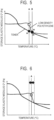
- FIG. 3 shows the results of viscoelasticity measurement.
- the horizontal axis indicates the temperature when the powder was heated under predetermined conditions, and the vertical axis indicates the storage elastic modulus of each powder at that time.
- the viscoelastic characteristics of the three powders showed the following tendencies.
- the toner shown by the solid line, is hard at low temperatures because it has a high storage elastic modulus. However, as the temperature rises, the storage elastic modulus gradually decreases, showing a tendency to soften almost linearly.
- the paste shown by the broken line was softer than the toner before heating, but the storage elastic modulus hardly changed until a predetermined temperature, and it was seen to soften sharply at around the melting point.
- polyethylene has low-density polyethylene and high-density polyethylene having different structures.
- Low-density polyethylene shown by the broken line has more branched structures than high-density polyethylene shown by the dotted line, so that it has a lower melting point. Therefore, it has the feature that it softens at a lower temperature, while high-density polyethylene has a higher melting point and softening temperature because its molecular structure is mainly linear.
- the level of occurrence of peeling offset differs depending on the compatibility and degree of mixing between the toner and the paste. Therefore, it is necessary to perform image formation in a state where the toner and paste are less compatible or less mixable, and create a crimped postcard.
- the viscoelastic characteristic as an index representing the ease of softening of a substance.
- peeling offset can be improved by creating a situation in which they are less compatible with each other. Therefore, the specific viscoelastic characteristics obtained this time will be described below.
- FIG. 4 shows the actual paper temperature during fixing and the paper temperature during press-bonding (that is, the temperature of the toner and paste on the paper) added to FIG. 3 .
- the paper temperature during fixing is indicated by a vertical solid line A
- the paper temperature during press-bonding is indicated by a vertical solid line B.
- the temperature during press-bonding B was set higher than that during fixing A.
- FIG. 5 shows the storage elastic moduli of the toner and the paste (low-density polyethylene) at the fixing and press-bonding temperatures as black and white circles to facilitate explaining the relationship between the viscoelastic characteristics and the peeling offset.
- the fixing time of the paste is simply shown as (1), the press-bonding time of the paste as (2), the fixing time of the toner as (3), and the press-bonding time of the toner as (4) for easy understanding. It was also found that peeling offset suppression is improved in the following three states, which will be explained in order.
- the first one is, as shown in FIG. 5 , that in this example, the paper temperature during press-bonding is set higher than during fixing, so that the viscoelasticity is (1) > (2) and (3) > (4).
- the paste does not need to completely melt during fixing, and since press-bonding is possible when the paste melts during press-bonding, (1) may be used in a state where it is slightly softened and starts to melt. That is, (1) only needs to be within the softening region in the viscoelastic characteristic.
- the third is considered to be the most important condition for suppressing peeling offset, which is to satisfy the relationship of (1) > (3) at the fixing temperature A as shown in FIG. 7 .
- the difference between the storage elastic modulus of (1) and the storage elastic modulus of (3) at the fixing temperature A is
- a wax layer can be formed on the surface of the toner in a state not compatible with the paste, which becomes a toner wall that makes it difficult for them to be compatible during press-bonding, thereby suppressing compatibility.
- the viscoelasticity of the paste during fixing > the viscoelasticity during press-bonding ((1) ⁇ (2)), the viscoelasticity of the toner during fixing > during press-bonding ((3) ⁇ (4)), and the viscoelasticity (1) of the paste during fixing being within the softening region in the viscoelastic characteristic, and the viscoelasticity of the paste ⁇ the viscoelasticity of the toner ((1) ⁇ (3)) during fixing.
- the solid line in FIG. 8 shows the viscoelasticity of the toner, which is sharper melting (easier to soften) than the broken line paste. Even if trying to change the positional relationship between (3) and (4), since the toner itself melts during fixing, the position of (3) is inevitable, and it is expected that the positional relationship between (3) and (4) in FIG. 8 occurs. (The viscoelasticity becomes lower than (3) because it is a thermoplastic resin). That is, it was found that only the solid line part at a temperature lower than (3) changes, and the positional relationship between (1), (2), (3), and (4) does not change.
- the paste can be fixed in a slightly softened state during fixing, and the entire paste can be brought into a melted state during press-bonding for the first time. This makes it possible to prevent the toner and paste from melting at once during fixing, creating a situation that is less compatible and improving peeling offset.
- the fixing temperature (paper temperature during fixing) was 95°C and the press-bonding temperature (paper temperature during press-bonding) was 105°C.
- the storage elastic modulus of the paste at the fixing temperature was 3 ⁇ 10 6 Pa
- the storage elastic modulus of the paste at the press-bonding temperature was 2 ⁇ 10 4 Pa
- the storage elastic modulus of the toner at the fixing temperature was 6 ⁇ 10 4 Pa
- the storage elastic modulus of the toner at the press-bonding temperature was 2 ⁇ 10 4 Pa.
- the level of occurrence of peeling offset varies depending on the compatibility and degree of mixing between the toner and the paste. Therefore, it is necessary to perform image formation in a state where the toner and the paste are less compatible or less likely to mix with each other, and create crimped postcards.
- the average particle diameter of the paste is about 25 ⁇ m larger than that of the toner, if the particle size distribution is wide (that is, the half width of the particle size distribution is large), or if there are many particles having a smaller particle diameter than the average particle diameter of the paste, it was found that peeling offset suppression improved.
- the improvement mechanism will be described below, and the necessary conditions will be presented.
- the average particle diameter and particle size distribution were measured as follows.
- the average particle diameter and particle size distribution of the toner and paste are calculated as follows.
- a precision particle size distribution measuring device "Coulter Counter Multisizer 3" (registered trademark, manufactured by Beckman Coulter, Inc.) equipped with an aperture tube having an aperture of 100 ⁇ m by a pore electrical resistance method is used.
- Setting of measurement conditions and analysis of measurement data are performed using the dedicated software "Beckman Coulter Multisizer 3 Version 3.51” (manufactured by Beckman Coulter, Inc.) attached to the device. The measurement is performed with an effective measurement channel number of 25,000 channels.
- an electrolyte aqueous solution used for the measurement one obtained by dissolving special grade sodium chloride in ion-exchanged water so that the concentration is 1% by mass, for example, "ISOTON II” (manufactured by Beckman Coulter, Inc.) can be used.
- ISOTON II manufactured by Beckman Coulter, Inc.
- the threshold and noise level are automatically set. Also, set the current to 1600 ⁇ A, the gain to 2, the electrolyte to ISOTON II, and check “Flash aperture tube after measurement.” On the "Conversion setting from pulse to particle size” screen of the dedicated software, set the bin interval to logarithmic particle size, the particle size bin to 256 particle size bins, and the particle size range from 2 ⁇ m to 60 ⁇ m.
- the specific measurement method is as follows.
- the steps in which the toner and paste exist as powders are any of the developing step of developing from the developer carrying member to the drum, the primary transfer step of transferring from the drum to the ITB, and the secondary transfer step of transferring from the ITB to the paper.
- the primary transfer step By forcibly stopping the main body drive and the like, it was found that mixing occurred in the primary transfer step as shown in FIG. 9C .
- both the paste 2 and the toner 8 are transferred onto the ITB 3, and are mixed at this point.
- FIG. 10A is a diagram schematically showing the state before the transfer pressure is applied, and the toner and paste are carried regularly on the drum in accordance with the print pattern.
- paste particles larger by about 25 ⁇ m than the toner disturb the toner image on the drum, and it can be confirmed that the toner infiltrates into the paste particles of a larger diameter. This is considered to be because larger particles with larger particle diameters are difficult to move due to their heavier weight, and lighter smaller particles move to enter the gaps.
- this state occurs on the ITB, when secondary transfer is performed to the paper, the paste layer overlaps on the disturbed toner layer on the paper, and the particles of both are further mixed. Then, as shown in FIG.
- the toner is fixed in positions different from normal during fixing in an isolated manner, and as shown in FIG. 11B , when the paper 4 is peeled off after press-bonding, the isolated toner is peeled off together with the paste, which has been found to be the cause of peeling offset.
- the average particle diameter of the paste is about 25 ⁇ m larger than that of the toner, and there are many particles having a smaller particle diameter than the average particle diameter of the paste (the paste has a wider particle size distribution, or a larger half width in the particle size distribution, than the toner), as shown in FIG. 12A , small paste particles having a smaller particle size than the large paste particles have already entered and filled the gaps between the large paste particles on the ITB. Therefore, even when the toner is transferred from the drum to the ITB at the downstream stations in the image formation and the transfer pressure is applied, the toner can be prevented from entering the gaps of the large paste particles as shown in FIG. 12B , suppressing the mixing of the toner and paste on the ITB.
- FIGS. 14A and 14B are graphs when there is a large difference in average particle diameter and particle size distribution between the toner and the paste in the upper right corner of Table 3.
- FIG. 14A shows a large average particle diameter and a large particle size distribution of the paste
- FIG. 14B shows a small average particle diameter and a small particle size distribution of the toner.
- the paste since the paste has a wide particle size distribution (that is, the half width of the particle size distribution is large), particles of various paste particle diameters fill the gaps on the ITB at the most upstream in the image forming process to form a smooth surface before the toner is printed in the next station.
- the gaps are filled with paste with a smaller average particle size as small as that of the toner particles, if the particle size distribution of the paste can be widened to be wider than that of the toner, i.e., if more particles close to the particle size of the other side are present in advance, they are less likely to mix with each other and thus peeling offsets can be controlled.
- FIGS. 15A and 15B are schematic diagrams showing the extent to which toner particles can infiltrate into the gaps of 30 ⁇ m paste, which is the maximum average particle diameter, (the view is from the plane side of the ITB surface, not the cross-sectional side).
- Table 4 shows the relationship between the particle diameter difference and peeling offset. [Table 4] Toner Particle Diameter ( ⁇ m) Paste Particle Diameter ( ⁇ m) Particle Diameter Difference ( ⁇ m) Infiltration into Gaps Peeling Offset 5 30 25 Yes Occurred 6 30 24 No Non Occurred
- the average particle diameter in this case assumes a maximum of 30 ⁇ m. Therefore, even if the average particle diameters of the toner and paste change, they are similar to the numerical values in Table 4, so that the situation where infiltration is easiest is when the average particle diameter is 30 ⁇ m at maximum, that is, the most severe situation is when the average particle diameter difference in Table 4 is 25 ⁇ m. Therefore, it has been found that peeling offset can be suppressed by making the difference in average particle diameter smaller than 25 ⁇ m.
- the SP value difference between the toner and the paste is set to 1.0 (cal/cm 3 ) 1/2 or more so that the toner and the paste are less likely to be compatible even in a molten state. Further, by giving a difference in viscoelastic properties between the toner and the paste during fixing, it is possible to avoid the two powders from melting at once, and to make them less compatible even in a state where the molten state and powder state are mixed. Further, by making the particle size distribution of the paste larger than that of the toner with the average particle diameter difference between the toner and the paste being less than 25 ⁇ m, the small particles of the paste enter the gaps of the large particles of the paste in advance to form a smooth surface. Since it can be made difficult to mix even in a powdery state, peeling offset can be favorably suppressed. In addition, the image quality and gloss of the peeled surface are improved (and the adhesive strength is partially improved).
- the image quality and gloss (adhesion strength) of the peeled surface can be further improved while suppressing peeling offset.
Landscapes
- Physics & Mathematics (AREA)
- General Physics & Mathematics (AREA)
- Spectroscopy & Molecular Physics (AREA)
- Chemical & Material Sciences (AREA)
- Organic Chemistry (AREA)
- Developing Agents For Electrophotography (AREA)
Abstract
Description
- The present invention relates to a method for producing a crimped sheet (or manufacturing a press-bonded sheet) such as crimped postcards, and an image forming apparatus having means for manufacturing a press-bonded sheet.
- Crimped postcards that seal confidential contents such as invoices and payroll statements require a predetermined adhesion strength so that they do not peel off during delivery, while at the same time it is an important element that they can be easily peeled off when they arrive at the user's location to open them.
- In addition, printers that create the above crimped postcards are highly convenient, from the viewpoint of simplicity and space saving, because they have a simple configuration that allows printing characters and images on a paper medium (hereinafter referred to as paper) and then conveying the paper as is, folding it and press-bonding it to create a crimped postcard.
- Such a printer configuration desirably has a process cartridge filled with a developer (hereinafter referred to as toner) for printing and a process cartridge filled with a powder adhesive (hereinafter referred to as paste) for press-bonding, mounted in the same printer body, and is capable of printing in accordance with a conventional electrophotographic image forming process and also of bonding by additionally being provided with a folding unit and a press-bonding unit, thus having a simple configuration.
- However, there are also problems that occur in performing a series of image forming processes by using two different types of powders. Specifically, if physical properties and conditions of the toner and the paste are not properly adjusted, they may be compatible or mixed with each other, and when opening a crimped postcard in which the
paste 2 and thetoner 8 are press-bonded by a foldedsheet 4 as shown inFIG. 2A , thetoner 8 printed on thesheet 4 may peel off together with thepaste 2, and cause such a phenomenon that the transferred toner is reflected in the white background area of the facing surface (hereinafter referred to as peeling offset), as shown inFIG. 2B . -
Patent Literature 1 clearly states that a hydrocarbon resin (polyethylene, etc.) is suitable as a material for the paste. - PTL 1:
Japanese Patent Application Laid-Open No. 2007-45861 - However, with regard to the problem of peeling offset mentioned above, only selection of the paste as in
Patent Literature 1 is insufficient for the manufacture of crimped postcards and for printers where printing and press-bonding processes are performed in a series of steps. It is necessary to select the materials, types, forms, etc. for not only the paste but also including the toner, based on their physical properties required. - Therefore, in view of the above situation, an object of the present invention is to propose an effective press-bonded sheet manufacturing method and an image forming apparatus capable of suppressing the occurrence of peeling offset when opening a crimped postcard while using an image forming apparatus capable of performing printing and press-bonding processes in a series of steps.
- The above object is achieved by adopting the following constitution.
- That is, the present invention relates to a method for manufacturing a press-bonded sheet in which sheet portions are press-bonded in a peelable state, comprising:
- a step of forming a composite layer by laminating an adhesive layer formed using a powder adhesive as a surface layer on a toner image formed using a printing toner on a sheet;
- a fixing step of heating the composite layer formed on the sheet to fix it to the sheet;
- a step of superimposing by opposing an area of the sheet where the composite layer is fixed and an area of the same sheet or a different sheet where another composite layer is fixed; and
- a press-bonding step of press-bonding the superimposed portion of the composite layer and the other composite layer by pressing under heat,
- wherein a difference in solubility parameter (SP value) between the printing toner and the powder adhesive is 1.0 (cal/cm3)1/2 or more.
- The present invention also relates to an image forming apparatus for manufacturing a press-bonded sheet in which sheet portions are press-bonded in a peelable state, comprising:
- means for forming a composite layer by laminating an adhesive layer formed using a powder adhesive as a surface layer on a toner image formed using a printing toner on a sheet;
- fixing means for heating the composite layer formed on the sheet to fix it to the sheet;
- means for superimposing by opposing an area of the sheet where the composite layer is fixed and an area of the same sheet or a different sheet where another composite layer is fixed; and
- press-bonding means for press-bonding the superimposed portion of the composite layer and the other composite layer by pressing under heat,
- wherein a difference in solubility parameter (SP value) between the printing toner and the powder adhesive is 1.0 (cal/cm3)1/2 or more.
- The present invention also relates to a method for manufacturing a press-bonded sheet in which sheet portions are press-bonded in a peelable state, comprising:
- a step of forming a composite layer by laminating an adhesive layer formed using a powder adhesive as a surface layer on a toner image formed using a printing toner on a sheet;
- a fixing step of heating the composite layer formed on the sheet to fix it to the sheet;
- a step of superimposing by opposing an area of the sheet where the composite layer is fixed and an area of the same sheet or a different sheet where another composite layer is fixed; and
- a press-bonding step of press-bonding the superimposed portion of the composite layer and the other composite layer by pressing under heat,
- wherein the printing toner contains wax,
- when a storage elastic modulus of the printing toner at a temperature in the fixing step is defined as G'(A1), a storage elastic modulus of the printing toner at a temperature in the press-bonding step is defined as G'(A2), a storage elastic modulus of the powder adhesive at a temperature in the fixing step is defined as G'(B 1), and a storage elastic modulus of the powder adhesive at a temperature in the press-bonding step is defined as G'(B2), the following relation is satisfied:


- the temperature in the fixing step is a temperature between a starting onset temperature and an ending onset temperature of a change region caused by melting in a storage elastic modulus curve of the powder adhesive.
- The present invention also relates to a method for manufacturing a press-bonded sheet in which sheet portions are press-bonded in a peelable state, comprising:
- a step of forming a composite layer by laminating an adhesive layer formed using a powder adhesive as a surface layer on a toner image formed using a printing toner on a sheet;
- a fixing step of heating the composite layer formed on the sheet to fix it to the sheet;
- a step of superimposing by opposing an area of the sheet where the composite layer is fixed and an area of the same sheet or a different sheet where another composite layer is fixed; and
- a press-bonding step of press-bonding the superimposed portion of the composite layer and the other composite layer by pressing under heat,
- wherein a difference in average particle diameter between the printing toner and the powder adhesive is smaller than 25 µm, and the powder adhesive has a wider particle size distribution, or a larger half width, than the printing toner.
- Furthermore, the present invention relates to an image forming apparatus for manufacturing a press-bonded sheet in which sheet portions are press-bonded in a peelable state, comprising:
- means for forming a composite layer by laminating an adhesive layer formed using a powder adhesive as a surface layer on a toner image formed using a printing toner on a sheet;
- fixing means for heating the composite layer formed on the sheet to fix it to the sheet;
- means for superimposing by opposing an area of the sheet where the composite layer is fixed and an area of the same sheet or a different sheet where another composite layer is fixed; and
- press-bonding means for press-bonding the superimposed portion of the composite layer and the other composite layer by pressing under heat,
- wherein a difference in average particle diameter between the printing toner and the powder adhesive is smaller than 25 µm, and the powder adhesive has a wider particle size distribution, or a larger half width, than the printing toner.
- By adopting the constitution of the present invention, it is possible to make the printing toner and the powder adhesive (paste) less compatible or less mixable with each other in an image forming apparatus capable of performing printing and press-bonding processes in a series of steps. Thereby, the occurrence of peeling offset when opening a crimped postcard is suppressed.
-
- [
FIG. 1 ]
FIG. 1 is a schematic diagram showing an example of the image forming apparatus according to the present invention. - [
FIG. 2A ]
FIG. 2A is a diagram for explaining the peeling offset phenomenon. - [
FIG. 2B ]
FIG. 2B is a diagram for explaining the peeling offset phenomenon. - [
FIG. 3 ]
FIG. 3 is an explanatory diagram showing viscoelastic characteristics in the examples and comparative examples of the present invention. - [
FIG. 4 ]
FIG. 4 is an explanatory diagram showing viscoelastic characteristics in the examples and comparative examples of the present invention, together with temperatures during fixing and press-bonding. - [
FIG. 5 ]
FIG. 5 is an explanatory diagram showing temperatures and viscoelastic characteristics during fixing and press-bonding of the developer (toner) and powder adhesive (paste) in an example of the present invention. - [
FIG. 6 ]
FIG. 6 is an explanatory diagram showing temperatures and viscoelastic characteristics during fixing of the powder adhesive (paste) in an example of the present invention. - [
FIG. 7 ]
FIG. 7 is an explanatory diagram showing temperatures and viscoelastic characteristics during fixing of the developer (toner) and powder adhesive (paste) in an example of the present invention. - [
FIG. 8 ]
FIG. 8 is an explanatory diagram showing temperatures and viscoelastic characteristics during fixing and press-bonding of the future developer (toner) and the powder adhesive (paste) in an example of the present invention, and viscoelastic characteristics of the future developer (toner). - [
FIG. 9A ]
FIG. 9A is a schematic diagram showing an example of the image forming apparatus according to the present invention. - [
FIG. 9B ]
FIG. 9B is a schematic diagram showing a contact state between the image bearing member (drum) and the intermediate transfer belt (ITB) at the 1st station of the image forming apparatus shown inFIG. 9A . - [
FIG. 9C ]
FIG. 9C is a schematic diagram showing a contact state between the image bearing member (drum) and the intermediate transfer belt (ITB) at the 2nd station of the image forming apparatus shown inFIG. 9A . - [
FIG. 10A ]
FIG. 10A is a schematic diagram showing a state immediately before contact between the image bearing member (drum) and the intermediate transfer belt (ITB) at the 2nd station in the case where there is a difference in average particle diameter in the example of the present invention. - [
FIG. 10B ]
FIG. 10B is a schematic diagram showing a state immediately after contact between the image bearing member (drum) and the intermediate transfer belt (ITB) at the 2nd station in the case where there is a difference in average particle diameter in the example of the present invention. - [
FIG. 11A ]
FIG. 11A is a schematic diagram showing a state before peeling of the crimped postcard when there is a difference in average particle diameter in the example of the present invention. - [
FIG. 11B ]
FIG. 11B is a schematic diagram showing a state after peeling of the crimped postcard when there is a difference in average particle diameter in the example of the present invention. - [
FIG. 12A ]
FIG. 12A is a schematic diagram showing a state immediately before contact between the image bearing member (drum) and the intermediate transfer belt (ITB) at the 2nd station when there is a difference in average particle diameter with a wider particle size distribution in the example of the present invention. - [
FIG. 12B ]
FIG. 12B is a schematic diagram showing a state immediately after contact between the image bearing member (drum) and the intermediate transfer belt (ITB) at the 2nd station when there is a difference in average particle diameter with a wider particle size distribution in the example of the present invention. - [
FIG. 13A ]
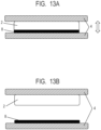
FIG. 13A is a schematic diagram showing a state before peeling of the crimped postcard when there is a difference in average particle diameter with a wider particle size distribution in the example of the present invention. - [
FIG. 13B ]
FIG. 13B is a schematic diagram showing a state after peeling of the crimped postcard when there is a difference in average particle diameter with a wider particle size distribution in the example of the present invention. - [
FIG. 14A ]
FIG. 14A is a diagram showing the average particle diameter and particle size distribution in the example of the present invention. - [
FIG. 14B ]
FIG. 14B is a diagram showing the average particle diameter and particle size distribution in the example of the present invention. - [
FIG. 15A ]
FIG. 15A is a schematic diagram showing gaps between particles of the developer (toner) and powder adhesive (paste) in the example of the present invention. - [
FIG. 15B ]
FIG. 15B is a schematic diagram showing gaps between particles of the developer (toner) and powder adhesive (paste) in the example of the present invention. - The steps (or means) on which the press-bonded sheet manufacturing method and image forming apparatus according to the present invention are based for manufacturing a press-bonded sheet in which sheet portions are press-bonded in a peelable state are:
- (i) a step of forming a composite layer by laminating an adhesive layer formed using a powder adhesive as a surface layer on a toner image formed using a printing toner on a sheet;
- (ii) a fixing step of heating the composite layer formed on the sheet to fix it to the sheet;
- (iii) a step of superimposing by opposing an area of the sheet where the composite layer is formed and fixed and an area of the same sheet or a different sheet where another composite layer is fixed; and
- (iv) a press-bonding step of press-bonding the superimposed portion of the composite layer and the other composite layer by pressing under heat.
- Here, in step (iii), when "different sheets" are superimposed, the operation of folding the sheet(s) is not necessarily involved, but when "sheet portions of the same sheet" are superimposed, the sheet will be folded. Therefore, the step (iii) above may be conveniently referred to as a "folding step," and the means for it may be referred to as "folding means" or "folding unit."
-
FIG. 1 is a schematic cross-sectional view showing an example of an image forming apparatus according to the present invention, which is based on a conventional full-color image forming apparatus with the addition of afolding unit 6 and a press-bonding unit 7. - Then, a process cartridge filled with
paste 2 is mounted on the station located on the most upstream side of the four image forming stations, and process cartridges of yellow (hereinafter referred to as Y), magenta (hereinafter referred to as M), and cyan (hereinafter referred to as C) toners are mounted on the other stations. However, the configuration is not limited to the above. Specifically, the order and quantity ratio of the paste and toner color process cartridges mounted on each station can be optionally set according to needs, such as monochrome. It is noted here that the number of stations is not limited to four. - Next, the image forming process (charging, developing, transferring, fixing) for creating crimped postcards, as well as the flow of the folding process and the press-bonding process will be described in detail.
- In the image forming apparatus of
FIG. 1 , an image bearing member (hereinafter referred to as a drum) 1 having an OPC photosensitive layer (organic photoconductor) is provided for each station, and is rotatable in the arrow direction at a predetermined process speed. After the surface of thedrum 1 is charged to a predetermined polarity and potential by a chargingroller 12 to which a charging bias is applied, an electrostatic latent image is formed by exposure to an exposure beam from alaser beam scanner 16. Then, the powder adhesive (hereinafter referred to as paste) 2 is carried from the developing container to the developingagent carrying member 17, and thepaste 2 is transferred to thedrum 1 by the developing means (contact charging and developing bias), that is, the electrostatic latent image is developed. - Next, the paste on the
drum 1 is (primarily) transferred to an intermediate transfer belt (hereinafter referred to as ITB) 3 that is in contact with the drum by a predetermined transfer pressure and a transfer bias of thetransfer roller 14, and thepaste 2 on theITB 3 is carried to the next station. A part of thepaste 2 that has not been transferred on thedrum 1 is scraped off by a cleaning blade or the like, and then thedrum 1 can perform repeated image formation by being charged, exposed, and developed again. The scrapedpaste 2 is collected and recovered in the cleaningcontainer 13. A configuration that can perform this series of processes (drum 1, chargingroller 12, developingcontainer 2, cleaning container 13) is integrated and cartridged, which is called a process cartridge. Four process cartridges containing different powders are arranged side by side and housed in the main body. - In the next station, in the same manner as described above, the Y toner (yellow toner) 8 is now transferred from the
drum 1 1 to the ITB. Then, as transfer is sequentially repeated in the subsequent stations, at least two layers of powders (paste and one color toner other than paste, up to paste,Y toner 8, M toner (magenta toner) 9, and C toner (cyan toner) 10) are sequentially stacked on the ITB. Then, the toner image is (secondarily) transferred from theITB 3 to the conveyed recording material (hereinafter referred to as paper) 4 by the transfer bias of thesecondary transfer roller 15. As a result, the stacking order on thepaper 4 is reversed from that on theITB 3, and a composite layer having a paste as a surface layer is formed on the toner image, thereby making it easy to stack and press-bond the sheet portions facing each other with paste. Therefore, in an apparatus using an intermediate transfer member such as an intermediate transfer belt, it is desirable to place the paste in the most upstream station in image formation. - Then, the paste is heated and pressurized by the fixing
unit 5 to melt and fix on thepaper 4 together with thetoners paste 2 is fixed in an appropriately softened state while melting. This is because if thetoners paste 2 are completely melted at the time of fixing, they become easily compatible and the peeling offset property decreases, and as in the following examples, the present invention makes ingenuity. - Next, the paper is sent to the
folding unit 6, folded there into a predetermined state, and then pressurized and heated by the press-bonding unit 7 to create a crimped postcard. It is important to perform this press-bonding at a temperature condition where the paste melts in order to maintain the adhesive strength of the crimped postcard while suppressing peeling offset. - The reason why the paste and toner are not melted at once during fixing but both are melted during press-bonding is as follows. The reason is that by fixing the paste by softening to the extent that it does not completely melt during fixing, the heat conduction to the paste becomes duller than that to the toner during press-bonding. Then, it is considered that a difference occurs in the ease of melting between them, making it possible to make a situation where both are less compatible at their interface, or the toner layer once melted during fixing allows wax to exist on the surface and this serves as a wall that makes the toner layer less compatible with the paste, making both less compatible.
- The crimped postcard created through the above steps is opened after arriving at the user. However, as described above, depending on the physical properties and conditions of the toner and paste, peeling offset may occur.
- As a result of studying the molten state and compatibility of the printing toner and paste, the inventors have found that good peelability can be obtained by controlling either
- 1. Difference in solubility parameter (SP value) between toner and paste
- 2. Difference in viscoelastic characteristics between toner and paste.
- In addition, as a result of studying the powder characteristics of the toner and paste, it was found that good peelability can be obtained by controlling 3. Difference in average particle diameter and particle size distribution between toner and paste.
- Hereinafter, the three control points will be described in order.
- Before explaining the three items contributing to the above-mentioned peeling offset, the toner and paste used in the present invention will be described first.
- The toner used in the present invention contains a thermoplastic binder resin such as a styrene acrylic resin, a polyester resin, a vinyl resin, or an acrylic resin, and further contains wax, colorant, external additive, charge control agent, magnetic material, etc. as needed. The shape of individual toner particles is spherical or irregular, and the average particle diameter is about 6 µm ± 2 µm. However, the material and physical properties are not limited to the above. In particular, in order to suppress the occurrence of peeling offset, the material and physical properties (structure) of the toner may be changed to match the material and physical properties of the paste, and those having different SP values, viscoelastic characteristics, average particle diameters, and particle size distributions may be used.
- On the other hand, polyethylene powder particles are preferably used for the paste. Polyethylene powder particles can be produced by polymerization method or pulverization method, and external additives etc. may be added to the surface. The shape of individual particles is spherical or irregular, and the average particle diameter is about 6 to 30 µm. However, the material and physical properties are not limited to the above. In particular, in order to suppress the occurrence of peeling offset, the material and physical properties (structure) of the paste may be changed to match the material and physical properties of the toner, and those having different SP values, viscoelastic characteristics, average particle diameters, and particle size distributions may be used.
- As described above, the level of occurrence of peeling offset differs depending on the compatibility and degree of mixing between the toner and paste. Therefore, it is necessary to perform image formation in a state where the toner and paste are less compatible or less mixable, and create a crimped postcard.
- Therefore, we focused on the SP value, which is an index representing the compatibility of two types of materials. This SP value is a value indicating the solubility of the two substances of interest and is a unique value determined by the material and molecular structure. In addition, it has the feature that if the SP values of two different substances are separated from each other, they are less compatible, and if the SP values are close, they are more compatible. Next, the method of calculating the SP value will be described.
- The SP value in the present invention was determined using the following Fedors equation. For the values of Δei and Δvi here, the present inventors referred to the evaporation energy and molar volume (25°C) of atoms and atomic groups in Tables 3 to 9 on pages 54 to 57 of "Coating no Kiso Kagaku (Fundamentals of Coating Science)," 1986 (Maki Shoten Publishing). Ev is evaporation energy, V is molar volume, Δei is evaporation energy of atom or atomic group of component i, and Δvi is molar volume of atom or atomic group of component i. For example, in the case of a substance called hexanediol, it consists of an atomic group (-OH) × 2 + (-CH2) × 6, and the SP value is obtained by the following formula as an example, and the SP value (δi) is 11.95.

SP value of hexanediol δi = [Δei / Δvi]1/2 = [{(5220) × 2 + (1180) × 6} / {(13) × 2 + (16.1) × 6}]1/2 = 11.95 - In this specification, the unit of SP value is (cal/cm3)1/2, where (cal/cm3)1/2 = 0.48888 × (J/cm3)1/2.
- In the present specification, the SP value of the toner is adopted as the SP value of the binder resin.
- In the present example, the following formulation toner was used. Toners having different resins shown in Table 1 below were obtained by changing the binder resin. Note that "parts" means "parts by mass."
- Next, a manufacture method of printing toners Ty, Tm, Tc will be exemplified. First, the following materials were prepared.
Styrene 60.0 parts Colorant 6.5 parts - The above materials were charged into an Attritor (manufactured by Mitsui Miike Machinery Co., Ltd.), and further dispersed for 5 hours at 220 rpm using zirconia particles having a diameter of 1.7 mm to obtain a pigment dispersion.
- In addition, the following materials were prepared.
Styrene 15.0 parts n-butyl acrylate 25.0 parts Polyester resin 4.0 parts Behenyl behenate 12.0 parts Divinylbenzene 0.5 parts - The above materials were mixed and added to the pigment dispersion. The resulting mixture was kept at 60°C, stirred at 500rpm using a T.K. Homomixer (manufactured by Tokushu Kika Kogyo Co., Ltd.) to uniformly dissolve and disperse, and a polymerizable monomer composition was prepared.
- On the other hand, 850.0 parts of a 0.10 mol / L-Na3PO4 aqueous solution and 8.0 parts of 10% hydrochloric acid were added to a container equipped with a high-speed stirrer Clearmix (manufactured by M Technique Co., Ltd.) and the rotation speed was adjusted to 15000 rpm and heated to 70°C. To this was added 127.5 parts of a 1.0 mol / L-CaCl2 aqueous solution to prepare an aqueous medium containing a calcium phosphate compound.
- After charging the polymerizable monomer composition into the aqueous medium, 7.0 parts of t-butyl peroxypivalate, a polymerization initiator, was added, granulated for 10 minutes while maintaining a rotation speed of 15000 rpm, then changed the stirrer from a high speed stirrer to a propeller stirrer, refluxed at 70°C for 5 hours, then set the liquid temperature to 85°C and further reacted for 2 hours.
- After completion of the polymerization reaction, the resulting slurry was cooled, hydrochloric acid was further added to the slurry to adjust the pH to 1.4, and stirred for 1 hour to dissolve the calcium phosphate salt. Thereafter, the slurry was washed with 3 times the amount of water, filtered, dried, classified to obtain toner particles.
- Then, with respect to 100.0 parts of the toner particles, 2.0 parts of silica fine particles (number average particle diameter of primary particles: 10 nm, BET specific surface area: 170 m2/g) subjected to hydrophobic treatment with dimethyl silicone oil (20% by mass) was added as an external additive. The toner particles containing the silica fine particles were mixed using a Mitsui Henschel Mixer (manufactured by Mitsui Miike Machinery Co., Ltd.) at 3000 rpm for 15 minutes to obtain toner (printing toner). The obtained toner had a weight average particle diameter of about 6 µm.
- Next, in order to investigate the compatibility between these toners and paste (powder adhesive), a plurality of pastes having different resin species as shown in Table 1 were used to perform the above-described image forming process, and the following test samples of crimped postcards were created to confirm peeling offset.
- The test samples were prepared by printing paste and any one color of Y, M, and C toners on the entire surface of the
inner surface 3 cm × 4 cm area of the strip (3 cm × 14 cm) of paper (GF-C081 manufactured by Canon) instead of the crimped postcard, and by printing only paste on the entire surface; the printed surfaces thereof were overlapped with each other facing inward, and fixing and press-bonding were performed to create each sample. In this case, the image forming process conditions (applied biases, settings of each component, temperature conditions, etc.) were performed under almost the same conditions for paste and toner, but may be set individually for each powder. In the test described later, the fixing temperature and the press-bonding temperature were raised to perform fixing and press-bonding in the test using high-density polyethylene for the paste. - The peeling test was performed using a TENSELON tensile tester manufactured by ORIENTEC, MODEL: RTG-1255. The both ends of the strip were clamped to the tester and peeled off at a tensile speed of 50 mm/min.
- The presence or absence of peeling offset was determined by checking the peeled surface of the strip peeled off with TENSILON and determining whether or not the toner had been transferred to the strip side printed only with paste. The results are explained below using Table 1.
- As shown in Table 1, when a polyester resin was used for both the toner and the paste, the materials are the same, so that the SP value is 9.30 for both. When a test sample was prepared in this state and a peeling test was performed, the peeled surfaces were compatible with each other, did not separate well, and peeling offset occurred. It was also confirmed that peeling offset occurred due to compatibility when both the toner and the paste have the same styrene acrylic resin.
- Next, a peeling test was performed by changing the toner to a polyester resin and the paste to a polypropylene resin having a similar SP value. As a result, it was confirmed that the toner and the paste were compatible and did not separate well. Therefore, it can be seen that the ease of compatibility depends on the closeness of SP values, not the material.
- Next, the case where the difference in SP value is large will be described. This time, the same test was conducted using two types of polyethylene having different structures, low-density polyethylene and high-density polyethylene, as the paste. The SP value of low-density polyethylene was 7.93 (the difference in SP value from the polyester contained in the toner was 1.37), and the SP value of high-density polyethylene was 8.29 (the difference in SP value from the polyester contained in the toner was 1.01). As a result, it was found that the separation surface did not compatibilize and the peeled surface was cleanly separated, smooth, and glossy with both polyethylenes. Therefore, it was found that mutual compatibility can be suppressed if the difference in SP value is at least 1.0. In addition, low-density polyethylene is preferable to high-density polyethylene in that image formation is possible under almost the same process conditions as the toner.
Table 1] Toner Paste SP Value Difference Peeling Offset Polyester Resin (9.30) Polyester Resin (9.30) 0.00 Occurred Styrene Acrylic Resin (9.40) Styrene Acrylic Resin (9.40) 0.00 Occurred Polyester Resin (9.30) Polypropylene Resin (9.30) 0.00 Occurred Polyester Resin (9.30) Low-Density Polyethylene (7.93) 1.37 Not Occurred Polyester Resin (9.30) High-Density Polyethylene (8.29) 1.01 Not Occurred - The above are the test results regarding the SP value, but next, model experiments to investigate peeling offset under conditions outside the normal use range were conducted while changing the combination of the materials of the toner and paste. The purpose of conducting this model experiment is twofold.
- The first purpose is to investigate whether compatibility can be suppressed even if the difference in SP value is less than 1.0, that is, how much margin there is, for example, whether 1.0 is the optimum value, and the second purpose is that the threshold of 1.0 for the SP value difference is established. It is to examine whether it is a condition only in the combination of the polyester resin as the toner and the polyethylene resin as the paste, that is, whether the same result can be obtained in other combinations.
- The model experiment will be described in detail. In this model experiment, the adhesion amount of the toner and paste on the above-mentioned strip was made non-uniform so as to easily cause peeling offset. By making the coating non-uniform, the toner is less likely to be connected to the surrounding toner when melted (the toner is more likely to be isolated), making it easier to peel off from the paper.
- Therefore, in this model experiment, peeling offset deteriorates when the toner and paste have the same SP value. The results are shown in Table 2 below.
- First, as shown in Table 2, when the toner was a polyester resin and the paste was low-density polyethylene and high-density polyethylene, when the above model experiment was conducted, peeling offset slightly occurred in the case of high-density polyethylene having an SP value difference of 1.01. On the other hand, peeling offset did not occur with low-density polyethylene having an SP value difference of 1.37.
- Also, when the toner was a styrene acrylic resin and the paste was low-density polyethylene and high-density polyethylene, both the normal peeling offset test and the model experiment were conducted. The differences in SP values between the toner and paste were 1.47 and 1.11, respectively. When the normal peeling test and the model experiment were conducted under these conditions, it was found that peeling offset did not occur with both low-density polyethylene with an SP value difference of 1.47 and high-density polyethylene with an SP value difference of 1.11.
- Therefore, it became clear that the difference in SP value for suppressing peeling offset was preferably 1.0 or more, and more preferably 1.1 or more.
[Table 2] Toner Paste SP Value Difference Peeling Offset Peeling Offset (Non-uniform Image) Polyester Resin (9.30) Polyester Resin (9.30) 0.00 Occurred Occurred Styrene Acrylic Resin (9.40) Styrene Acrylic Resin (9.40) 0.00 Occurred Occurred Polyester Resin (9.30) Polypropylene Resin (9.30) 0.00 Occurred Occurred Polyester Resin (9.30) Low-Density Polyethylene (7.93) 1.37 Not Occurred Not Occurred Polyester Resin (9.30) High-Density Polyethylene (8.29) 1.01 Not Occurred Slightly Occurred Styrene Acrylic Resin (9.40) Low-Density Polyethylene (7.93) 1.47 Not Occurred Not Occurred Styrene Acrylic Resin (9.40) High-Density Polyethylene (8.29) 1.11 Not Occurred Not Occurred - Next, the viscoelastic characteristic, which is another factor of the peeling offset, will be described. The reason for focusing on this viscoelastic characteristic will be described later.
- From the viewpoint of viscoelastic characteristics, the present invention needs to satisfy


- Here, the viscoelastic characteristic indicates the energy stored in the powder relative to the applied strain, and is represented by the storage elastic modulus with respect to temperature. In the case of powders such as thermoplastic resins as in the present example, when the toner or paste is heated and the temperature is raised, the viscoelastic characteristic changes and the storage elastic modulus decreases. This state indicates that the toner or paste has melted and softened (hereinafter referred to as softening).
- If the paste is close to a single material state, the softening temperature is close to the melting point, so that the viscoelasticity tends to change sharply in the temperature region around that temperature. However, when multiple materials such as toner contain multiple materials, the regions where the viscoelasticity changes for each substance are different, so that there is a tendency that the region where rapid change occurs is small in number, and there is a feature that the viscoelasticity gradually changes according to the heating temperature. Next, a method for measuring the viscoelastic characteristics of the toner and paste will be described.
- For the measurement of the viscoelastic characteristics, that is, storage elastic modulus, of the toner and paste, DMA8000 (manufactured by PerkinElmer, Inc.) and a compression fixture (product number: N533-0320) were used, and a heating furnace product number: N533-0267 was used for the measurement. First, as a measurement sample, under an environment at 25°C, toner or paste (about 2.0 g) was pressure molded (compressed and molded at about 10 MPa for about 60 seconds) into a disk shape having a diameter of 7.9 mm and a thickness of 2.0 ± 0.3 mm using a tablet molding machine (for example, NT-100H, manufactured by NPa SYSTEM CO., LTD.), and measured while heating to create a graph of storage elastic modulus versus heating temperature.
- In the present example, the toner has the same composition, manufacture process, particle size, etc. as in Example 1 for the measurement of viscoelasticity.
- That is, the binder resin of the toner was a styrene acrylic resin containing wax as a release agent, and polyethylene was used for the paste, but the materials of the toner and paste are not limited thereto. What is necessary is that the viscoelastic characteristics of the toner and the paste are those having different material qualities, and as long as the storage elastic modulus of the paste is higher than that of the toner at least at the fixing temperature, peeling offset can be suppressed, so that the materials of the toner and paste are not limited thereto.
-
FIG. 3 shows the results of viscoelasticity measurement. The horizontal axis indicates the temperature when the powder was heated under predetermined conditions, and the vertical axis indicates the storage elastic modulus of each powder at that time. The viscoelastic characteristics of the three powders showed the following tendencies. - The toner, shown by the solid line, is hard at low temperatures because it has a high storage elastic modulus. However, as the temperature rises, the storage elastic modulus gradually decreases, showing a tendency to soften almost linearly.
- On the other hand, the paste shown by the broken line was softer than the toner before heating, but the storage elastic modulus hardly changed until a predetermined temperature, and it was seen to soften sharply at around the melting point.
- However, polyethylene has low-density polyethylene and high-density polyethylene having different structures. Low-density polyethylene shown by the broken line has more branched structures than high-density polyethylene shown by the dotted line, so that it has a lower melting point. Therefore, it has the feature that it softens at a lower temperature, while high-density polyethylene has a higher melting point and softening temperature because its molecular structure is mainly linear.
- As described above, the level of occurrence of peeling offset differs depending on the compatibility and degree of mixing between the toner and the paste. Therefore, it is necessary to perform image formation in a state where the toner and paste are less compatible or less mixable, and create a crimped postcard.
- Therefore, we focused on the viscoelastic characteristic as an index representing the ease of softening of a substance. There are actually two heating timings, during fixing and during press-bonding, when creating a crimped postcard. By using the difference in viscoelasticity between the toner and paste at these two temperatures, we have found that peeling offset can be improved by creating a situation in which they are less compatible with each other. Therefore, the specific viscoelastic characteristics obtained this time will be described below.
-
FIG. 4 shows the actual paper temperature during fixing and the paper temperature during press-bonding (that is, the temperature of the toner and paste on the paper) added toFIG. 3 . The paper temperature during fixing is indicated by a vertical solid line A, and the paper temperature during press-bonding is indicated by a vertical solid line B. In this example, the temperature during press-bonding B was set higher than that during fixing A. - The viscoelastic characteristics of each powder at the fixing time A will be described. At the fixing time A, the toner was almost melted, and the low-density polyethylene, which was the paste, was slightly melted. However, high-density polyethylene was hardly melted.
- Next, the viscoelastic characteristics of each powder at the time B of press-bonding will be described. At the time B of press-bonding, although the toner and low-density polyethylene were almost melted, it was found that high-density polyethylene was not melted and fixed. In this example, since the paste was fixed at the same temperature setting as the toner, the paste used is desirably low-density polyethylene instead of high-density polyethylene, which is difficult to fix. Therefore, hereinafter, low-density polyethylene is used as the paste to explain how to suppress peeling offset.
-
FIG. 5 shows the storage elastic moduli of the toner and the paste (low-density polyethylene) at the fixing and press-bonding temperatures as black and white circles to facilitate explaining the relationship between the viscoelastic characteristics and the peeling offset. FromFIG. 5 , the fixing time of the paste is simply shown as (1), the press-bonding time of the paste as (2), the fixing time of the toner as (3), and the press-bonding time of the toner as (4) for easy understanding. It was also found that peeling offset suppression is improved in the following three states, which will be explained in order. - The first one is, as shown in
FIG. 5 , that in this example, the paper temperature during press-bonding is set higher than during fixing, so that the viscoelasticity is (1) > (2) and (3) > (4). - Second, as shown in
FIG. 6 , the paste does not need to completely melt during fixing, and since press-bonding is possible when the paste melts during press-bonding, (1) may be used in a state where it is slightly softened and starts to melt. That is, (1) only needs to be within the softening region in the viscoelastic characteristic. - The third is considered to be the most important condition for suppressing peeling offset, which is to satisfy the relationship of (1) > (3) at the fixing temperature A as shown in
FIG. 7 . Here, it is preferable that the difference between the storage elastic modulus of (1) and the storage elastic modulus of (3) at the fixing temperature A is |Log10(1 × 10⁵) - Log10(3 × 10⁴)| or more and |Log10(3 × 10⁶) - Log10(6 × 10⁴)| or less. - This is because it was found that if the viscoelastic characteristics of both the toner and paste are similar at the time of fixing and both powders melt at once, they become easily compatible and compatibilize to the extent that peeling offset occurs by the end of fixing. Therefore, in order to improve peeling offset, it is necessary to fix the paste in a state where it is slightly softened without completely melting during fixing. That is, by fixing the paste in a slightly softened state during fixing, the entire paste can be brought into a melted state during press-bonding for the first time. That is, peeling offset can be improved by making a state where both powders are not melted during fixing and are less compatible.
- In addition, depending on the type of toner, by melting mainly the toner during fixing, a wax layer can be formed on the surface of the toner in a state not compatible with the paste, which becomes a toner wall that makes it difficult for them to be compatible during press-bonding, thereby suppressing compatibility.
- Regarding the temperature and pressure conditions during the press-bonding process, if the temperature or pressure is quite high during the press-bonding process, peeling offset is likely to occur. Therefore, as conditions during press-bonding, it is desirable to perform press-bonding at a paper temperature of about 105°C to 115°C, a paper feed rate of 100 mm/s, and a pressure of 32 kg (load of 16 kg × 2 on one side).
- From the above, in order to improve peeling offset due to viscoelastic characteristics, it suffices to satisfy the following relationships: the viscoelasticity of the paste during fixing > the viscoelasticity during press-bonding ((1) ≥ (2)), the viscoelasticity of the toner during fixing > during press-bonding ((3) ≥ (4)), and the viscoelasticity (1) of the paste during fixing being within the softening region in the viscoelastic characteristic, and the viscoelasticity of the paste ≥ the viscoelasticity of the toner ((1) ≥ (3)) during fixing.
- Furthermore, we assumed a case where the slope of change (softening region slope) in the viscoelastic characteristic of the toner becomes steeper than that of the paste as the material development of the toner progresses in the future. The assumed situation is shown in
FIG. 8 . - The solid line in
FIG. 8 shows the viscoelasticity of the toner, which is sharper melting (easier to soften) than the broken line paste. Even if trying to change the positional relationship between (3) and (4), since the toner itself melts during fixing, the position of (3) is inevitable, and it is expected that the positional relationship between (3) and (4) inFIG. 8 occurs. (The viscoelasticity becomes lower than (3) because it is a thermoplastic resin). That is, it was found that only the solid line part at a temperature lower than (3) changes, and the positional relationship between (1), (2), (3), and (4) does not change. - From the above, by maintaining the above relationship, the paste can be fixed in a slightly softened state during fixing, and the entire paste can be brought into a melted state during press-bonding for the first time. This makes it possible to prevent the toner and paste from melting at once during fixing, creating a situation that is less compatible and improving peeling offset.
- In this example, the fixing temperature (paper temperature during fixing) was 95°C and the press-bonding temperature (paper temperature during press-bonding) was 105°C. Further, the storage elastic modulus of the paste at the fixing temperature was 3 × 10⁶ Pa, the storage elastic modulus of the paste at the press-bonding temperature was 2 × 10⁴ Pa, the storage elastic modulus of the toner at the fixing temperature was 6 × 10⁴ Pa, and the storage elastic modulus of the toner at the press-bonding temperature was 2 × 10⁴ Pa.
- As described above, the level of occurrence of peeling offset varies depending on the compatibility and degree of mixing between the toner and the paste. Therefore, it is necessary to perform image formation in a state where the toner and the paste are less compatible or less likely to mix with each other, and create crimped postcards.
- Therefore, we focused on the state where the toner and paste exist as powders before fixing and press-bonding, and thought that peeling offset could be suppressed by improving the mixing state between them.
- When the average particle diameter and particle size distribution of the toner and paste were confirmed by shaking, no peeling offset occurred if a series of image forming processes was employed to create a crimped postcard, followed by peeling, in the case where the average particle diameter and particle size distribution of the toner and paste were the same. However, when the average particle diameter of the toner and the paste was different and the average particle diameter of the paste was about 25 µm larger than that of the toner, it was found that peeling offset occurred markedly. On the other hand, even if the average particle diameter of the paste is about 25 µm larger than that of the toner, if the particle size distribution is wide (that is, the half width of the particle size distribution is large), or if there are many particles having a smaller particle diameter than the average particle diameter of the paste, it was found that peeling offset suppression improved. The improvement mechanism will be described below, and the necessary conditions will be presented. The average particle diameter and particle size distribution were measured as follows.
- The average particle diameter and particle size distribution of the toner and paste, that is, the weight average particle diameter, are calculated as follows. As a measuring device, a precision particle size distribution measuring device "
Coulter Counter Multisizer 3" (registered trademark, manufactured by Beckman Coulter, Inc.) equipped with an aperture tube having an aperture of 100 µm by a pore electrical resistance method is used. Setting of measurement conditions and analysis of measurement data are performed using the dedicated software "Beckman Coulter Multisizer 3 Version 3.51" (manufactured by Beckman Coulter, Inc.) attached to the device. The measurement is performed with an effective measurement channel number of 25,000 channels. - As an electrolyte aqueous solution used for the measurement, one obtained by dissolving special grade sodium chloride in ion-exchanged water so that the concentration is 1% by mass, for example, "ISOTON II" (manufactured by Beckman Coulter, Inc.) can be used. Prior to measurement and analysis, set the dedicated software as follows. On the "Change Standard Measurement Method (SOM)" screen of the dedicated software, set the total count number in the control mode to 50000 particles, set the number of measurements to 1, and set the value obtained using "Standard Particles 10.0 µm" (manufactured by Beckman Coulter, Inc.) as the Kd value. By pressing the "Measurement button for threshold / noise level," the threshold and noise level are automatically set. Also, set the current to 1600 µA, the gain to 2, the electrolyte to ISOTON II, and check "Flash aperture tube after measurement." On the "Conversion setting from pulse to particle size" screen of the dedicated software, set the bin interval to logarithmic particle size, the particle size bin to 256 particle size bins, and the particle size range from 2 µm to 60 µm. The specific measurement method is as follows.
- (1) 200 mL of electrolyte aqueous solution is put into a 250mL glass round bottom beaker dedicated for
Multisizer 3 and set on a sample stand, and stirred counterclockwise at 24 revolutions/second with a stirrer rod. Then, dirt and air bubbles in the aperture tube are removed using the "Flash aperture tube" function of the dedicated software. - (2) 30 mL of electrolyte aqueous solution is put into a 100 mL glass flat bottom beaker. To this is added 0.3 mL of a dilution obtained by diluting "Contaminon N" (a 10 mass% aqueous solution of
pH 7 precision measuring instrument cleaning neutral detergent consisting of nonionic surfactant, anionic surfactant, and an organic builder, manufactured by Wako Pure Chemical Industries) 3 times by mass with ion-exchanged water. - (3) Prepare an ultrasonic dispersion system "Ultrasonic Dispersion System Tetora 150" (manufactured by Nikkaki Bios, Co., Ltd.) with a built-in two oscillators having an oscillation frequency of 50 kHz shifted in phase by 180 degrees and an electrical output of 120 W. Put 3.3L of ion-exchanged water in the water tank of the ultrasonic disperser and add 2mL of Contaminon N thereto.
- (4) Set the beaker of (2) above in the beaker fixing hole of the ultrasonic disperser described above, operate the ultrasonic disperser. Then, adjust the height position of the beaker so that the resonance state of the liquid surface of the electrolyte aqueous solution in the beaker becomes maximum.
- (5) With ultrasonic waves applied to the electrolyte aqueous solution in the beaker of (4) above, add the toner or paste little by little so that it becomes 10 mg, disperse it in the electrolyte aqueous solution, and further ultrasonically disperse it for 60 seconds. When dispersing with ultrasonic waves, the water temperature in the water tank is appropriately adjusted to be 10°C or higher and 40°C or lower.
- (6) Using a pipette, the electrolyte aqueous solution in (5) above with dispersed toner or powder adhesive is added dropwise to the round bottom beaker in (1) placed in the sample stand so that the measurement concentration is adjusted to 5%. Then, the measurement is performed until the number of measured particles reaches 50000.
- (7) The measurement data is analyzed by the dedicated software attached to the device to calculate the weight average particle diameter.
- Next, the location where the toner and paste are mixed was identified in the state where the above-mentioned peeling offset occurs.
- In the image forming process, the steps in which the toner and paste exist as powders are any of the developing step of developing from the developer carrying member to the drum, the primary transfer step of transferring from the drum to the ITB, and the secondary transfer step of transferring from the ITB to the paper. By forcibly stopping the main body drive and the like, it was found that mixing occurred in the primary transfer step as shown in
FIG. 9C . In this step, both thepaste 2 and thetoner 8 are transferred onto theITB 3, and are mixed at this point. -
FIG. 10A is a diagram schematically showing the state before the transfer pressure is applied, and the toner and paste are carried regularly on the drum in accordance with the print pattern. However, when the transfer pressure is applied, as shown inFIG. 10B , paste particles larger by about 25 µm than the toner disturb the toner image on the drum, and it can be confirmed that the toner infiltrates into the paste particles of a larger diameter. This is considered to be because larger particles with larger particle diameters are difficult to move due to their heavier weight, and lighter smaller particles move to enter the gaps. When this state occurs on the ITB, when secondary transfer is performed to the paper, the paste layer overlaps on the disturbed toner layer on the paper, and the particles of both are further mixed. Then, as shown inFIG. 11A , the toner is fixed in positions different from normal during fixing in an isolated manner, and as shown inFIG. 11B , when thepaper 4 is peeled off after press-bonding, the isolated toner is peeled off together with the paste, which has been found to be the cause of peeling offset. - On the other hand, when the average particle diameter of the toner and the paste is the same, there are many contact points between the layers at the timing when they are mixed with each other, and the transfer pressure can be absorbed by the surface on the ITB. Therefore, it is considered that peeling offset did not occur.
- In the case where the average particle diameter of the paste is about 25 µm larger than that of the toner, and there are many particles having a smaller particle diameter than the average particle diameter of the paste (the paste has a wider particle size distribution, or a larger half width in the particle size distribution, than the toner), as shown in
FIG. 12A , small paste particles having a smaller particle size than the large paste particles have already entered and filled the gaps between the large paste particles on the ITB. Therefore, even when the toner is transferred from the drum to the ITB at the downstream stations in the image formation and the transfer pressure is applied, the toner can be prevented from entering the gaps of the large paste particles as shown inFIG. 12B , suppressing the mixing of the toner and paste on the ITB. Then, it has been found that as shown inFIG. 13A , the toner and paste are not mixed with each other during fixing, and are fixed while maintaining the layers of each other, and as shown inFIG. 13B , when thepaper 4 is peeled off after press-bonding, the toner and paste are peeled off without disturbing the interface, and peeling offset does not occur. - In addition to the above combination of toner and paste, other combinations as shown in Table 3 can be considered. From Table 3, it can be seen that peeling offset occurs in the combination of small toner average particle diameter and large paste average particle diameter, and peeling offset suppression is improved with a larger particle size distribution than with a smaller particle size distribution. In particular, it can be seen that the effect of the large particle size distribution of the paste is large.
- However, since the data in parentheses contribute less to peeling offset, this example focuses on combinations with a large particle size difference, namely toner with a small average particle size (about 6 µm), and paste with small (about 6 µm) and large (about 30 µm) average particle sizes.
[Table 3] Paste Small Avg. Particle Size Small Particle Size Distribution Small Avg. Particle Size Large Particle Size Distribution Large Avg. Particle Size Small Particle Size Distribution Large Avg. Particle Size Large Particle Size Distribution Toner Small Avg. Particle Size Small Particle Size Distribution Not Occurred Not Occurred Toner is disturbed, and peeling offset occurs. Not Occurred Small Avg. Particle Size Large Particle Size Distribution Not Occurred Not Occurred Toner is disturbed, and peeling offset occurs. Not Occurred Large Avg. Particle Size Small Particle Size Distribution Paste is disturbed followed by decreased adhesive strength, and peeling offset occurs verv slightly. Paste is disturbed followed by decreased adhesive strength, and peeling offset occurs verv slightly. Not Occurred Not Occurred Large Avg. Particle Size Large Particle Size Distribution Not Occurred Not Occurred Not Occurred Not Occurred - Next, the reason why peeling offset suppression is improved by increasing the particle size distribution of the paste will be described.
FIGS. 14A and 14B are graphs when there is a large difference in average particle diameter and particle size distribution between the toner and the paste in the upper right corner of Table 3.FIG. 14A shows a large average particle diameter and a large particle size distribution of the paste, andFIG. 14B shows a small average particle diameter and a small particle size distribution of the toner. In this case, since the paste has a wide particle size distribution (that is, the half width of the particle size distribution is large), particles of various paste particle diameters fill the gaps on the ITB at the most upstream in the image forming process to form a smooth surface before the toner is printed in the next station. In particular, since the gaps are filled with paste with a smaller average particle size as small as that of the toner particles, if the particle size distribution of the paste can be widened to be wider than that of the toner, i.e., if more particles close to the particle size of the other side are present in advance, they are less likely to mix with each other and thus peeling offsets can be controlled. - Next, the reason why peeling offset improves when the threshold value of the average particle diameter difference between the toner and the paste is smaller than 25 µm will be described.
FIGS. 15A and 15B are schematic diagrams showing the extent to which toner particles can infiltrate into the gaps of 30 µm paste, which is the maximum average particle diameter, (the view is from the plane side of the ITB surface, not the cross-sectional side). - From
FIG. 15A , when the toner is 5 µm and the paste is 30 µm, and the average particle diameter difference is 25 µm, the toner infiltrates into the paste gaps while in contact with them, making it easier for the powders to mix with each other, resulting in worse peeling offset. On the other hand, fromFIG. 15B , when the toner is 6 µm and the paste is 30 µm, and the average particle diameter difference is 24 µm, it becomes physically difficult for the toner to infiltrate into the gaps of the paste, making it difficult for the powders to mix with each other. As a result, peeling offset can be suppressed. - Table 4 shows the relationship between the particle diameter difference and peeling offset.
[Table 4] Toner Particle Diameter (µm) Paste Particle Diameter (µm) Particle Diameter Difference (µm) Infiltration into Gaps Peeling Offset 5 30 25 Yes Occurred 6 30 24 No Non Occurred - For the numerical values in Table 4, since the electrophotographic image forming process is used for both the toner and the paste, the average particle diameter in this case assumes a maximum of 30 µm. Therefore, even if the average particle diameters of the toner and paste change, they are similar to the numerical values in Table 4, so that the situation where infiltration is easiest is when the average particle diameter is 30 µm at maximum, that is, the most severe situation is when the average particle diameter difference in Table 4 is 25 µm. Therefore, it has been found that peeling offset can be suppressed by making the difference in average particle diameter smaller than 25 µm.
- From the above, with respect to the average particle diameter and particle size distribution of the toner and paste, it has become clear that peeling offset suppression is improved when the difference in average particle diameter between the toner and paste is less than 25 µm and the paste has a larger particle size distribution, that is, a larger half width, than that of the toner.
- The advantages of the present invention examples are shown in Table 5.
[Table 5] Configuration Relationship between Toner and Paste Peeling Offset Image Quality of Peeled Surface (Improvement in Glossiness) Example 1 SP Value Difference ≥ 1.0 Not Occurred Good Example 2 Has Difference in Viscoelasticity Not Occurred Good Example 3 Particle Diameter Difference < 25 µm, Particle Size Distribution: Paste > Toner Not Occurred Good Example 4 Satisfies Configurations of All Examples 1 to 3 Not Occurred Excellent - In this case, the SP value difference between the toner and the paste is set to 1.0 (cal/cm3)1/2 or more so that the toner and the paste are less likely to be compatible even in a molten state. Further, by giving a difference in viscoelastic properties between the toner and the paste during fixing, it is possible to avoid the two powders from melting at once, and to make them less compatible even in a state where the molten state and powder state are mixed. Further, by making the particle size distribution of the paste larger than that of the toner with the average particle diameter difference between the toner and the paste being less than 25 µm, the small particles of the paste enter the gaps of the large particles of the paste in advance to form a smooth surface. Since it can be made difficult to mix even in a powdery state, peeling offset can be favorably suppressed. In addition, the image quality and gloss of the peeled surface are improved (and the adhesive strength is partially improved).
- By combining all of the above configurations, that is, the SP value difference, viscoelastic difference, average particle diameter, and particle size distribution difference, the image quality and gloss (adhesion strength) of the peeled surface can be further improved while suppressing peeling offset.
- The present invention is not limited to the above examples, and various changes and modifications can be made without departing from the spirit and scope of the present invention. Therefore, the following claims are appended to publicly disclose the scope of the present invention.
- This application claims the benefit of
Japanese Patent Application No. 2021-160246, filed September 30, 2021 Japanese Patent Application No. 2022-147741, filed September 16, 2022 -
- 1 Image bearing member (drum: 1st station)
- 2 Powder adhesive (paste)
- 3 Intermediate transfer belt (ITB)
- 4 Recording material (paper)
- 5 Fixing unit
- 6 Folding unit
- 7 Press-bonding unit
- 8 Toner (Y: yellow)
- 9 Toner (M: magenta)
- 10 Toner (C: cyan)
- 11 Image bearing member (drum: 2nd station)
- 12 Charging roller
- 13 Cleaning container
- 14 Transfer roller
- 15 Secondary transfer roller
- 16 Laser beam scanner
- 17 Developing agent carrying member
Claims (10)
- A method for manufacturing a press-bonded sheet in which sheet portions are press-bonded in a peelable state, comprising:a step of forming a composite layer by laminating an adhesive layer formed using a powder adhesive as a surface layer on a toner image formed using a printing toner on a sheet;a fixing step of heating the composite layer formed on the sheet to fix it to the sheet;a step of superimposing by opposing an area of the sheet where the composite layer is fixed and an area of the same sheet or a different sheet where another composite layer is fixed; anda press-bonding step of press-bonding the superimposed portion of the composite layer and the other composite layer by pressing under heat,wherein a difference in solubility parameter (SP value) between the printing toner and the powder adhesive is 1.0 (cal/cm3)1/2 or more.
- The method for manufacturing a press-bonded sheet according to claim 1, wherein the powder adhesive contains low-density polyethylene.
- An image forming apparatus for manufacturing a press-bonded sheet in which sheet portions are press-bonded in a peelable state, comprising:means for forming a composite layer by laminating an adhesive layer formed using a powder adhesive as a surface layer on a toner image formed using a printing toner on a sheet;fixing means for heating the composite layer formed on the sheet to fix it to the sheet;means for superimposing by opposing an area of the sheet where the composite layer is fixed and an area of the same sheet or a different sheet where another composite layer is fixed; andpress-bonding means for press-bonding the superimposed portion of the composite layer and the other composite layer by pressing under heat,wherein a difference in solubility parameter (SP value) between the printing toner and the powder adhesive is 1.0 (cal/cm3)1/2 or more.
- The image forming apparatus according to claim 3, wherein the powder adhesive contains low-density polyethylene.
- A method for manufacturing a press-bonded sheet in which sheet portions are press-bonded in a peelable state, comprising:a step of forming a composite layer by laminating an adhesive layer formed using a powder adhesive as a surface layer on a toner image formed using a printing toner on a sheet;a fixing step of heating the composite layer formed on the sheet to fix it to the sheet;a step of superimposing by opposing an area of the sheet where the composite layer is fixed and an area of the same sheet or a different sheet where another composite layer is fixed; anda press-bonding step of press-bonding the superimposed portion of the composite layer and the other composite layer by pressing under heat,wherein the printing toner contains wax,when a storage elastic modulus of the printing toner at a temperature in the fixing step is defined as G'(A1), a storage elastic modulus of the printing toner at a temperature in the press-bonding step is defined as G'(A2), a storage elastic modulus of the powder adhesive at a temperature in the fixing step is defined as G'(B 1), and a storage elastic modulus of the powder adhesive at a temperature in the press-bonding step is defined as G'(B2), the following relation is satisfied:


 the temperature in the fixing step is a temperature between a starting onset temperature and an ending onset temperature of a change region caused by melting in a storage elastic modulus curve of the powder adhesive.
 - The method for manufacturing a press-bonded sheet according to claim 5, wherein the powder adhesive contains low-density polyethylene.
- A method for manufacturing a press-bonded sheet in which sheet portions are press-bonded in a peelable state, comprising:a step of forming a composite layer by laminating an adhesive layer formed using a powder adhesive as a surface layer on a toner image formed using a printing toner on a sheet;a fixing step of heating the composite layer formed on the sheet to fix it to the sheet;a step of superimposing by opposing an area of the sheet where the composite layer is fixed and an area of the same sheet or a different sheet where another composite layer is fixed; anda press-bonding step of press-bonding the superimposed portion of the composite layer and the other composite layer by pressing under heat,wherein a difference in average particle diameter between the toner and the powder adhesive is smaller than 25 µm, and the powder adhesive has a wider particle size distribution, or a larger half width, than the toner.
- The method for manufacturing a press-bonded sheet according to claim 7, wherein the powder adhesive contains low-density polyethylene.
- An image forming apparatus for manufacturing a press-bonded sheet in which sheet portions are press-bonded in a peelable state, comprising:means for forming a composite layer by laminating an adhesive layer formed using a powder adhesive as a surface layer on a toner image formed using a printing toner on a sheet;fixing means for heating the composite layer formed on the sheet to fix it to the sheet;means for superimposing by opposing an area of the sheet where the composite layer is fixed and an area of the same sheet or a different sheet where another composite layer is fixed; andpress-bonding means for press-bonding the superimposed portion of the composite layer and the other composite layer by pressing under heat,wherein a difference in average particle diameter between the toner and the powder adhesive is smaller than 25 µm, and the powder adhesive has a wider particle size distribution, or a larger half width, than the toner.
- The image forming apparatus according to claim 9, wherein the powder adhesive contains low-density polyethylene.
Applications Claiming Priority (3)
| Application Number | Priority Date | Filing Date | Title |
|---|---|---|---|
| JP2021160246 | 2021-09-30 | ||
| JP2022147741A JP7600194B2 (en) | 2021-09-30 | 2022-09-16 | Method for manufacturing pressure-bonded sheet and image forming apparatus |
| PCT/JP2022/035835 WO2023054311A1 (en) | 2021-09-30 | 2022-09-27 | Method for producing crimped sheet and image forming apparatus |
Publications (2)
| Publication Number | Publication Date |
|---|---|
| EP4410920A1 true EP4410920A1 (en) | 2024-08-07 |
| EP4410920A4 EP4410920A4 (en) | 2025-12-31 |
Family
ID=85782691
Family Applications (1)
| Application Number | Title | Priority Date | Filing Date |
|---|---|---|---|
| EP22876177.1A Pending EP4410920A4 (en) | 2021-09-30 | 2022-09-27 | METHOD FOR PRODUCE A CURLED FILM AND IMAGE PROCESSING DEVICE |
Country Status (3)
| Country | Link |
|---|---|
| US (1) | US20240239624A1 (en) |
| EP (1) | EP4410920A4 (en) |
| WO (1) | WO2023054311A1 (en) |
Families Citing this family (3)
| Publication number | Priority date | Publication date | Assignee | Title |
|---|---|---|---|---|
| EP4446814A3 (en) * | 2023-04-10 | 2025-02-19 | FUJIFILM Business Innovation Corp. | Image forming system, image forming method, and crimping toner image forming apparatus |
| EP4446815A3 (en) * | 2023-04-10 | 2025-01-22 | FUJIFILM Business Innovation Corp. | Image forming system, image forming method, and crimping toner image forming apparatus |
| JP2025006206A (en) | 2023-06-29 | 2025-01-17 | キヤノン株式会社 | Image forming apparatus and booklet production method |
Family Cites Families (6)
| Publication number | Priority date | Publication date | Assignee | Title |
|---|---|---|---|---|
| US6929835B2 (en) * | 2002-03-01 | 2005-08-16 | Kyocera Corporation | Antisolvent-laminate body |
| JP2007045861A (en) | 2005-08-05 | 2007-02-22 | Casio Electronics Co Ltd | Crimping postcard adhesive |
| JP2008149638A (en) * | 2006-12-20 | 2008-07-03 | Casio Electronics Co Ltd | Crimp printed matter preparation method and adhesive application method thereof |
| JP6411978B2 (en) * | 2015-09-24 | 2018-10-24 | 株式会社沖データ | Image forming apparatus |
| JP2021160246A (en) | 2020-03-31 | 2021-10-11 | ブラザー工業株式会社 | Image recording device |
| JP2022147741A (en) | 2021-03-23 | 2022-10-06 | 富士フイルムビジネスイノベーション株式会社 | Method for manufacturing toner for electrostatic charge image development, and toner for electrostatic charge image development |
-
2022
- 2022-09-27 WO PCT/JP2022/035835 patent/WO2023054311A1/en not_active Ceased
- 2022-09-27 EP EP22876177.1A patent/EP4410920A4/en active Pending
-
2024
- 2024-03-29 US US18/622,053 patent/US20240239624A1/en active Pending
Also Published As
| Publication number | Publication date |
|---|---|
| US20240239624A1 (en) | 2024-07-18 |
| WO2023054311A1 (en) | 2023-04-06 |
| EP4410920A4 (en) | 2025-12-31 |
Similar Documents
| Publication | Publication Date | Title |
|---|---|---|
| EP4410920A1 (en) | Method for producing crimped sheet and image forming apparatus | |
| US8165508B2 (en) | Developer loading method, loaded developer accommodating container, developer replenishment device, and image forming apparatus | |
| CN102692832B (en) | Toner group, developer group, handle box group, image processing system and method | |
| US8139982B2 (en) | Image formation apparatus and printed item | |
| JP5729354B2 (en) | Image forming method | |
| JP5560830B2 (en) | Electrostatic latent image developing toner, electrostatic latent image developing developer, toner cartridge, process cartridge, and image forming apparatus | |
| EP3686680A1 (en) | Image forming apparatus and image forming method | |
| JP7600194B2 (en) | Method for manufacturing pressure-bonded sheet and image forming apparatus | |
| US12405561B2 (en) | Press-bonded sheet manufacturing method, press-bonded sheet manufacturing apparatus, and image forming apparatus | |
| JP7797152B2 (en) | Image forming apparatus, adhesive cartridge, adhesive container, and process cartridge set | |
| JP7706956B2 (en) | Sheet bonding device | |
| JP4765768B2 (en) | Image forming method | |
| US12372910B2 (en) | Image forming apparatus having sheet bonding apparatus | |
| CN118020032A (en) | Method for producing laminated sheet and image forming apparatus | |
| JP7562349B2 (en) | Image forming device | |
| JP7556004B2 (en) | Pressure-bonded sheet manufacturing method | |
| CN116774543A (en) | Carrier for electrostatic charge image development and its manufacturing method, developer and its application | |
| US12443134B2 (en) | Booklet forming device and image forming apparatus | |
| CN118159616A (en) | Press-bonded sheet manufacturing method, press-bonded sheet manufacturing apparatus, and image forming apparatus | |
| JP2013033130A (en) | Developer for replenishment | |
| JP2025012205A (en) | Sheet thermocompression device and multifunction machine | |
| JP4808012B2 (en) | Toner, toner manufacturing method and process cartridge | |
| JP2024062665A (en) | toner | |
| JP2001075306A (en) | toner | |
| JP2000105484A (en) | Electrophotographic toner and image forming method |
Legal Events
| Date | Code | Title | Description |
|---|---|---|---|
| STAA | Information on the status of an ep patent application or granted ep patent |
Free format text: STATUS: THE INTERNATIONAL PUBLICATION HAS BEEN MADE |
|
| PUAI | Public reference made under article 153(3) epc to a published international application that has entered the european phase |
Free format text: ORIGINAL CODE: 0009012 |
|
| STAA | Information on the status of an ep patent application or granted ep patent |
Free format text: STATUS: REQUEST FOR EXAMINATION WAS MADE |
|
| 17P | Request for examination filed |
Effective date: 20240430 |
|
| AK | Designated contracting states |
Kind code of ref document: A1 Designated state(s): AL AT BE BG CH CY CZ DE DK EE ES FI FR GB GR HR HU IE IS IT LI LT LU LV MC MK MT NL NO PL PT RO RS SE SI SK SM TR |
|
| DAV | Request for validation of the european patent (deleted) | ||
| DAX | Request for extension of the european patent (deleted) | ||
| A4 | Supplementary search report drawn up and despatched |
Effective date: 20251202 |
|
| RIC1 | Information provided on ipc code assigned before grant |
Ipc: C09J 123/06 20060101AFI20251126BHEP Ipc: G03G 9/08 20060101ALI20251126BHEP Ipc: G03G 9/097 20060101ALI20251126BHEP Ipc: G03G 15/24 20060101ALI20251126BHEP |