EP4410730A1 - Breaking device - Google Patents
Breaking device Download PDFInfo
- Publication number
- EP4410730A1 EP4410730A1 EP23382082.8A EP23382082A EP4410730A1 EP 4410730 A1 EP4410730 A1 EP 4410730A1 EP 23382082 A EP23382082 A EP 23382082A EP 4410730 A1 EP4410730 A1 EP 4410730A1
- Authority
- EP
- European Patent Office
- Prior art keywords
- braking
- force
- friction element
- braking device
- actuating means
- Prior art date
- Legal status (The legal status is an assumption and is not a legal conclusion. Google has not performed a legal analysis and makes no representation as to the accuracy of the status listed.)
- Granted
Links
Images

Classifications
-
- B—PERFORMING OPERATIONS; TRANSPORTING
- B66—HOISTING; LIFTING; HAULING
- B66B—ELEVATORS; ESCALATORS OR MOVING WALKWAYS
- B66B29/00—Safety devices of escalators or moving walkways
Definitions
- the present invention relates to a braking device for braking a shaft of an escalator.
- the present invention relates to an escalator having a braking device.
- An escalator is a passenger transportation device for overcoming a distance. If a height distance is overcome, stair treads are formed in the device by moving segments, for example metal segments. Escalators are mainly known from public facilities with high public traffic, for example department stores, train stations and airports. Although they have a slower conveying speed than, for example, elevators, they offer the advantage that they may accommodate significantly more people. If the segments, for example metal segments, do not form a staircase but a flat surface, the means of passenger transportation is called a moving walk. Moving walks may be of horizontal or inclined design. Escalators or moving walks generally result in the accelerated and orderly transportation of people. This may serve to save time and space, for example.
- auxiliary brakes of escalators or moving walks are installed on their main drive shaft.
- the auxiliary brake is designed to block the rotation of the main drive shaft.
- the auxiliary brake has projections arranged on the circumference of the main drive shaft.
- at least one brake wedge is applied in the direction of the projections.
- the at least one brake wedge engages in at least one recess formed by two projections arranged circumferentially, causing an instantaneous stop of the main drive shaft.
- the abrupt stop may cause persons using the escalator or moving walkway during the braking process to fall forward due to mass inertia and injure themselves.
- a braking device for an escalator is described below.
- the task is to provide a safe escalator and to overcome the aforementioned disadvantages.
- a braking device for braking a shaft of an escalator.
- the braking device comprising
- a braking device for an escalator is described.
- the braking device may also be used for a moving walkway.
- escalator and moving walkway are interchangeable in both the description and the claims.
- a preferred effect is that the braking device performs soft braking on an escalator.
- Braking by the braking device may be activated in particular manually by a person, by actuating an actuating sensor, for example a button, or automatically by a control unit of the escalator, for example by autonomously detecting a fault or a hazardous situation.
- the brake disc of the braking device may be arranged on a shaft of the escalator in a rotationally fixed manner.
- the brake disc may be connected to the shaft for this purpose in a non-detachable manner, in particular by a welded connection or the like, or in a detachable manner, in particular by a screw connection or the like.
- the braking force applied by the at least one friction element may be reliably transmitted to the shaft of the escalator via the at least one braking surface of the brake disc.
- the at least one braking surface comprises a respective main extension plane.
- the at least one braking surface may be formed by the brake disc itself.
- the at least one braking surface may be formed as an additional wear-resistant wear body.
- the wear body may be connected to the brake disc, in particular on the axial side, in a releasable or non-releasable rotationally fixed manner. Due to a detachable connection of the brake disc to the wear body, the wear body may be replaced quickly and inexpensively during maintenance work. Removal and replacement of the entire brake disc may thus be avoided.
- the at least one friction element may be displaced parallel and perpendicular to the main extension plane of the at least one braking surface and apply the braking force to the at least one braking surface in a frictionally engaged manner.
- the displacement may be performed only parallel or parallel and perpendicular to the same or different parts.
- the at least one friction element acts on the at least one braking surface by the actuating means and/or may be spaced apart from the at least one braking surface.
- the at least one friction element may comprise a friction body for applying the braking force to the at least one braking surface.
- the friction body may in particular be releasably or non-releasably connected to the at least one friction element.
- the braking force may thus be applied to the at least one braking surface of the brake disc in a frictionally engaged manner by the at least one friction element itself or by the friction body of the at least one friction element.
- the at least one friction element may apply a braking force to the brake disc, in particular perpendicular to the main extension plane of the at least one braking surface.
- the braking force acts parallel to the normal vector of the main extension plane of the at least one braking surface.
- the fact that the brake disc is designed for a rotationally fixed attachment to the shaft means that the brake disc rotates with the shaft.
- the actuating means may be designed in particular as a linear actuating means.
- the actuating means may transmit a linear movement at least indirectly, or directly, to the at least one friction element.
- the actuating means is designed in particular as an electromagnetic actuating means. This means that the braking device may be controlled electronically. This simplifies the operation of the braking device by an actuating sensor, for example a button, or a control unit of the escalator.
- the braking speed of the braking device may be adjusted via the coefficient of friction of the at least one braking surface, in particular the wear body, and the at least one friction element, in particular the friction body.
- a lower coefficient of friction leads to a lower braking speed.
- a lower braking speed thereby leads to a softer braking, which increases the comfort of use for persons on the escalator.
- a high coefficient of friction of the at least one braking surface, in particular the wear body, and the at least one friction element, in particular the friction body leads to a high braking speed. In this case, a high braking speed leads to harder braking, which brings the escalator to a halt quickly and safely.
- the braking speed of the escalator may be adjusted alternatively or additionally by the actuating means during operation. If required, the actuating means may also be operated in the opposite direction and move the at least one friction element in the direction of the brake disc. As a result, the braking speed is increased.
- braking surface is used in the context of the present disclosure, this may be used for only one braking surface or for several, for example two, braking surfaces of a brake disc. The same applies at least to the friction element.
- the braking device comprises at least one spring element for at least indirectly applying a spring force to the at least one friction element in order to apply the braking force to the at least one braking surface via the at least one friction element, wherein in particular the spring force of the spring element acts parallel to the main extension plane of the at least one braking surface.
- the at least one spring element is in particular a helical spring, a disc spring or the like.
- the spring element may be designed in particular as a compression spring.
- safe application of the spring force to the at least one friction element may still be ensured even if the spring element should break during operation of the escalator.
- the braking device would still be able to bring about braking of the escalator even with a broken spring element by pressing the at least two broken spring segments against each other.
- the braking speed of the escalator may be adjusted. This enables safe braking and at the same time prevents the escalator from coming to an abrupt stop and people on the escalator falling and injuring themselves.
- a soft braking of the escalator may be set via a spring element with low spring force.
- the actuating means may support the spring element when the at least one friction element acts on the at least one braking surface. As a result, a higher braking speed is achieved if required.
- the at least one friction element may be acted upon by an actuating force generated by the actuating means for spacing the at least one friction element from the at least one braking surface, wherein in particular the actuating force of the actuating means acts parallel to the main extension plane of the at least one braking surface.
- the actuating means may cause the at least one friction element to act on the brake disc with its actuating force.
- the actuating means for spacing the at least one friction element from the at least one braking surface may in particular be actuated manually by a person via an actuating sensor, for example a button, or automatically by a control unit.
- the actuating means may be driven electrically.
- the actuating means counteracts the spring force of the spring element with its actuating force in the activated state.
- the actuating force generated by the actuating means may always be greater than the spring force of the spring element. As a result, the actuating force causes the spring element to be clamped.
- the energy stored in the spring element in the form of the spring force may be at least partially discharged after the actuating force ceases by at least indirectly acting on the at least one friction element.
- the actuating means holds the braking device in an open position, i.e. a non-braking position, during normal operation. In a hazardous situation or power failure, the actuating means is deactivated and braking of the escalator is automatically effected by applying the spring force of the spring element to the at least one friction element.
- the at least one friction element is adapted to be acted upon by a clamping force generated by the actuating means for acting on the at least one friction element on the at least one braking surface, wherein in particular the clamping force of the actuating means acts parallel to the main extension plane of the at least one braking surface.
- the actuating means may adapted to cause the at least one friction element to act on the brake disc with its clamping force.
- the actuating means for applying the at least one friction element to the at least one braking surface may be controlled in particular manually by a person via an actuating sensor, for example a button, or automatically by a control unit.
- the actuating means may be driven electrically.
- the clamping force of the actuating means acts parallel to the spring force of the spring element. The clamping force generated by the actuating means acts together with the spring force of the spring element on the at least one friction element.
- braking of the escalator may be performed quickly and safely by applying more force to the at least one friction element on the corresponding braking surface of the brake disc.
- the additional clamping force means that the spring element may be dimensioned smaller. This favors a space-saving and cost-effective braking device.
- a braking device with soft braking, caused by the spring force of the spring element may be realized in a normal operation and reinforced braking, caused by the spring force of the spring element together with the clamping force of the actuating means, is realized in a hazardous situation.
- the braking device comprises a holding device for immovable connection to a frame structure of the escalator and/or a building section surrounding the escalator, wherein in particular the holding device is designed for mounting the friction element and/or the actuating means.
- the holding device may be arranged in a stationary manner in the region of the shaft of the escalator in such a way that the holding device may interact with the further components of the braking device.
- the holding device may be formed from several support components.
- components of the braking device for example the actuating means, the at least one friction element, the spring element or the like, may be connected to the holding device.
- the holding device may be arranged in particular on the frame structure of the escalator and/or a building section surrounding the escalator.
- the holding device allows the braking device to be mounted on almost any shaft of the escalator.
- the braking device may act on the shaft of the escalator from any radial direction of the brake disc, as far as the installation space permits. This facilitates assembly and increases the possible applications of the braking device.
- the holding device which in particular comprises at least one holding bar, extends at least in sections parallel to the main extension plane of the at least one braking surface and comprises a receiving surface for receiving and displaceably guiding the at least one friction element, wherein the receiving surface including a holding bar inclination angle with respect to the at least one braking surface.
- the receiving surface may be designed in such a way that the at least one friction element may be displaced on the receiving surface by sliding, rolling and/or the like. Due to the holding bar inclination angle at the receiving surface, a displacement of the at least one friction element extending parallel to the main extension plane may result in an axial approach or spacing of the at least one friction element from the brake disc.
- the receiving surface has at least one guide element for guiding the at least one friction element on the receiving surface.
- the at least one guide element may be integrally formed with a portion of the holding device, in particular with the holding bar.
- the at least one guide element is formed as a separate component for attachment to the receiving surface and/or a section of the holding device, in particular to the holding bar.
- the at least one guide element is designed for lateral delimitation of the receiving surface.
- the at least one guide element comprises at least one projection and/or at least one groove for form-fitting limitation of at least one direction of movement of the corresponding friction element.
- the at least one friction element is designed as a clamping wedge with a friction surface and a guide surface arranged opposite the friction surface;
- the at least one friction element By forming the at least one friction element as a clamping wedge, the at least one friction element may be displaced with its guide surface along the receiving surface of the holding device parallel to the main extension plane of the at least one braking surface and at the same time axially approached to the brake disc or axially spaced from the brake disc, wherein the at least one friction surface of the at least one friction element always remains aligned parallel to the main extension plane of the at least one braking surface.
- the at least one friction element may be designed in particular as a one-sided clamping wedge.
- a one-sided clamping wedge forms a special embodiment of the clamping wedge in which two side surfaces, in particular the friction surface and the guide surface, converge at an acute angle, in particular the clamping wedge pitch angle. This ensures that the friction surface is applied to the braking surface over the entire surface.
- the magnitude of the holding bar inclination angle and the magnitude of the clamping wedge pitch angle are substantially equal; and in particular comprise an acute angle smaller/including 45 degrees.
- An acute angle of 45 degrees in terms of magnitude may cause an equal amount of displacement in the parallel and perpendicular directions of the at least one friction element with respect to the main extension plane of the at least one braking surface. Due to the differently adjustable angles, the displacement path of the at least one friction element may be variably adjusted. As a result, the distance from the at least one friction element to the at least one braking surface may be adjusted. In particular, the braking speed with which the at least one friction element applies the braking force to the at least one braking surface is thereby adjusted.
- the at least one friction element in particular the clamping wedge, is designed in such a way that a displacement of the at least one friction element extending parallel to the main extension plane of the at least one braking surface along the receiving surface simultaneously results in a displacement of the at least one friction element extending perpendicular to the main extension plane of the at least one braking surface for spacing or applying the at least one braking surface.
- the actuating means is operatively connected to the at least one friction element via a transmission arrangement.
- the transmission arrangement may transmit the force applied by the actuator, in particular actuating force or clamping force, and/or the spring force applied by the spring element to the at least one friction element with or without a transmission ratio.
- the force applied by the actuating means may be deflected by the transmission arrangement.
- the installation position of the actuating means may be adapted to the installation space provided by the escalator.
- the transmission arrangement is designed in such a way that at least two friction elements are simultaneously operatively connected to the actuating means via the transmission arrangement.
- the braking power of the braking device may be increased and thus, at the same time, the braking device is dimensioned smaller. This favors a space-saving braking device.
- the transmission arrangement may in particular comprise at least one longitudinal body for transmitting the actuating force, the spring force and/or the clamping force to the at least one friction element.
- the transmission arrangement may in particular comprise at least one joint for supporting the at least one longitudinal body.
- the at least one longitudinal body may in particular be operatively connected by a first end portion to the at least one joint and by a second end portion to the at least one friction element.
- the at least one joint may be movably supported and allow a perpendicular movement of the at least one longitudinal body with respect to the main extension plane of the at least one braking surface.
- the at least one longitudinal body may be resiliently configured, wherein the at least one longitudinal body is configured to be bendable perpendicular to the main extension plane of the at least one braking surface.
- the at least one friction element is operatively connected to the actuating means and/or the spring element in a displaceable manner parallel and perpendicular to the main extension plane of the at least one braking surface.
- the spring element applies a spring force to the at least one friction element via the transmission arrangement, wherein the spring element is mounted with a first end on a section of the holding device, in particular a support bar, and with a second end on the transmission arrangement.
- the at least one friction element may be acted upon by the spring force of the spring element via the transmission arrangement.
- the spring element may be clamped, in particular via the transmission arrangement, by the applied actuating force or the clamping force of the actuating means.
- the spring force of the spring element may counteract the actuating force or the clamping force.
- the spring force of the spring element counteracts the actuating force of the actuating means in order to be able to bring about safe braking by the spring force of the spring element in the event of a failure of the actuating means.
- the transmission arrangement may extend longitudinally along the main extension axis of the spring element.
- the transmission arrangement may have a spring bearing extending transversely to the longitudinal direction of the transmission arrangement for supporting the spring element.
- the position of the spring bearing on the transmission arrangement and/or the position of the support bar on the holding device may be variably adjusted.
- the spring travel of the spring element may be adjusted by the position of the spring bearing and/or the support bar.
- the spring force of the spring element may be adapted to the required braking power of the braking device on the escalator. This favors a flexible usability of the braking device of the escalator and increases the use of common parts.
- the transmission arrangement may extend in particular through a section of the holding device, in particular the support bar. This enables a particularly space-saving braking device.
- the brake disk is formed in multiple parts, wherein the brake disk is adapted to be connected to the shaft in particular in a substance-locking, form-fitting, force-fitting, frictional and/or force-forming manner.
- the brake disc of the braking device may be arranged on the shaft of the escalator in a rotationally fixed manner.
- the brake disc may be connected to the shaft for this purpose in a non-detachable manner, in particular by a welded connection, or in a detachable manner, in particular by a screw connection or the like.
- the brake disc may be of multi-part design. This means that the brake disc may be retrofitted to the shaft of an existing escalator to prevent it from rotating. The shaft does not have to be removed for installation.
- the brake disc may be formed from two halves. This reduces the assembly effort of the braking device.
- an actuating force of the actuating means acts counter to a spring force of a spring element; and/or wherein a clamping force of the actuating means acts in the direction of a/the spring force of a/the spring element; and/or wherein the actuating means is designed as a linear actuating means, in particular as an electromagnetic actuating means.
- the direction of the actuating force of the actuating means may act in opposition to the direction of the spring force of the spring element.
- the actuating means may use the actuating force to distance the at least one friction element from the brake disc and thus cancel the braking of the escalator.
- the actuating force may be greater than the spring force.
- the spring element may be preloaded by the actuating force of the actuating means. In the event of danger or power failure, the actuating means may thus be switched off and the braking of the escalator may be performed by the spring force of the preloaded spring element. This enables a particularly safe braking device that initiates braking of the escalator even in the event of a power failure.
- the direction of the clamping force of the actuating means may act in particular in the direction of the spring force of the spring element.
- the actuating means may act on the at least one friction element in the direction of the brake disc by means of the clamping force and thus bring about braking of the escalator.
- various braking behaviors of the braking device may be realized. For example, soft braking of the escalator may be brought about by the spring force of the spring element.
- the actuating means may provide the clamping force for rapid braking in addition to the spring force of the spring element. In this way, the braking behavior of the braking device is adapted to the situation at hand.
- the actuating means may be designed in particular as a linear actuating means.
- the actuating means is adapted to transmit a linear movement indirectly to the at least one friction element.
- the actuating means is designed in particular as an electromagnetic actuating means. This means that the braking device may be controlled electronically. This simplifies operation of the braking device, for example by an actuating sensor, for example a button, or a control unit of the escalator.
- the braking device comprises one, two or more friction elements, each of which is designed to apply a braking force to the brake disc on one side or both sides.
- the brake disc comprises at least one braking surface on each of its opposite axial end faces, it being possible for a braking force to be applied to the respective braking surfaces from two opposite axial directions by at least one friction element in each case.
- the holding device, in particular the holding bar, and the friction elements may be designed with mirror symmetry along the radial extent of the brake disc. This allows the braking properties of the braking device to be further enhanced. This favors the use of smaller braking devices. In particular, this may prevent one-sided axial loading of the brake disk, which could lead to bending of the brake disk or loosening of the brake disk from the shaft.
- the transmission arrangement may be formed mirror-symmetrically along the radial extension of the brake disc. Thus, a safe and space-saving braking device is realized.
- the task is further solved by an escalator with a braking device, wherein the braking device acts on a shaft of the escalator.
- the escalator may have one or more shafts.
- the escalator is provided for traversing a conveying distance.
- the conveying distance may be horizontal or overcoming a height.
- the escalator may further comprise at least one step belt and at least one deflection mechanism.
- the deflection mechanism comprises, for example, deflection rollers located at each end of a conveying path.
- One of the shafts may, for example, be part of a deflection mechanism of the escalator for deflecting a step belt of the escalator.
- a braking element may be provided to act on the respective shaft.
- escalator for the purposes of the overall disclosure is also considered to be an escalator.
- Figure 1 shows a braking device 10 for braking a shaft 12 of an escalator, with a brake disc 14 arranged non-rotatably on the shaft 12 and two friction elements 18 which are each mounted displaceably on a holding bar 23 of a holding device 22 and each apply a braking force axially to a braking surface 16 of the brake disc 14.
- the holding device 22 is rigidly attached to a frame structure of the escalator.
- the braking surfaces 16 each have a main extension plane E.
- the friction elements 18 are designed as clamping wedges 19 and may be acted upon parallel to the main extension plane E indirectly via a transmission arrangement 25 by a spring element 20 and/or an actuating means 26.
- the respective clamping wedges 19 are designed as single-sided clamping wedges, each with a friction surface 28 and a guide surface 30 arranged opposite the friction surface 28.
- the guide surface 30 includes a clamping wedge pitch angle beta/ ⁇ with respect to the respective braking surface 16, or with respect to the respective main extension plane E.
- the holding bars 23 each have a receiving surface 24 for contacting the guide surface 30 of the respective friction element 18, and each have two laterally attached guide elements 40 for positively limiting the respective friction element 18.
- the receiving surface 24 of the respective holding bar 23 encloses a holding bar inclination angle alpha/a with respect to the respective braking surface 16, or with respect to the respective main extension plane E.
- the spring element 20 is designed as a helical spring, in particular a compression spring, and is mounted between a support bar 32 of the holding device 22 and a spring bearing 34 of the transmission arrangement 25.
- the actuating means 26 is designed as a linear electromagnetic motor and is operatively connected to the transmission arrangement 25. The actuating force of the actuating means 26 counteracts the spring force of the spring element 20.
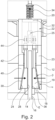
- Fig. 2 shows a top view of a section of the braking device 10 illustrated in Fig. 1 , wherein the braking device 10 is shown in the closed position, i.e. in a state in which the shaft 12 of the escalator is braked.
- the braking device 10 When the braking device 10 is closed, the braking force may be transmitted to the shaft 12 of the escalator via the friction elements 18.
- the actuating means 26 is in particular deactivated or disconnected from the power supply and no longer acts on the transmission arrangement 25 with the actuating force.
- the spring element 20 applies a spring force acting parallel to the main extension plane E to the friction elements 18 in each case.
- the friction elements 18 are displaced along the receiving surface 24 and are frictionally applied by the holding bar 23 of the holding device 22 to the braking surfaces 16 of the brake disc 14.
- the brake disc 14 transmits the braking force to the shaft 12 of the escalator causing it to stop.
- the actuating means 26 may also apply a clamping force acting in the direction of the spring force to the friction elements 18 via the transmission arrangement 25, in particular via the joints 44 and the longitudinal bodies 42. In this way, the braking speed of the braking device 10 may be additionally increased in the event of danger and safe braking of the escalator may be brought about.
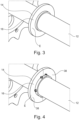
- Fig. 3 and Fig. 4 show a brake disc 14, which may be formed in one piece ( Fig. 3 ) or in several pieces ( Fig. 4 ) and may be attached to the shaft 12 of the escalator in a rotationally fixed manner.
- the one-piece brake disc 14 may be preassembled on the shaft 12 by sliding the brake disc 14, which is designed as a perforated disc, axially onto the shaft 12. Subsequently, the brake disc 14 may be bolted and/or welded to the shaft 12 in a rotationally fixed manner.
- the multi-part brake disc 14 formed from partial sections 38 of a perforated disc may, in particular, be subsequently arranged on the shaft 12 in a rotationally fixed manner. Once the braking surfaces 16 of the brake disc 14 are in a common axial plane, the partial sections 38 may be screwed and/or welded to the shaft 12 in a rotationally fixed manner.
Landscapes
- Braking Arrangements (AREA)
Abstract
a brake disc (14) designed to be fixed in rotation to the shaft (12) of the escalator, the brake disc (14) having at least one braking surface (16) with a respective main extension plane (E)
at least one friction element (18) displaceably mounted parallel and perpendicular to the main extension plane (E) for frictionally applying a braking force to the at least one braking surface (16); and
an actuating means (26) for spacing and/or applying the at least one friction element (18) from the at least one braking surface (16).
Description
- The present invention relates to a braking device for braking a shaft of an escalator.
- Further, the present invention relates to an escalator having a braking device.
- Passenger transportation devices, in particular escalators or moving walks, assume great importance in many facilities. An escalator is a passenger transportation device for overcoming a distance. If a height distance is overcome, stair treads are formed in the device by moving segments, for example metal segments. Escalators are mainly known from public facilities with high public traffic, for example department stores, train stations and airports. Although they have a slower conveying speed than, for example, elevators, they offer the advantage that they may accommodate significantly more people. If the segments, for example metal segments, do not form a staircase but a flat surface, the means of passenger transportation is called a moving walk. Moving walks may be of horizontal or inclined design. Escalators or moving walks generally result in the accelerated and orderly transportation of people. This may serve to save time and space, for example.
- The safety of persons during the use of escalators and moving walks always has top priority. In particular, escalators and moving walks must be able to stop quickly and safely in the event of danger. An essential component for the safety of escalators and moving walks is therefore a suitable braking device.
- Usually, auxiliary brakes of escalators or moving walks are installed on their main drive shaft. The auxiliary brake is designed to block the rotation of the main drive shaft. For this purpose, the auxiliary brake has projections arranged on the circumference of the main drive shaft. When the auxiliary brake is actuated, at least one brake wedge is applied in the direction of the projections. In the process, the at least one brake wedge engages in at least one recess formed by two projections arranged circumferentially, causing an instantaneous stop of the main drive shaft. The abrupt stop may cause persons using the escalator or moving walkway during the braking process to fall forward due to mass inertia and injure themselves.
- A braking device for an escalator is described below.
- Based on this situation, it is an object of the present invention to provide an improved braking device for braking an escalator.
- In particular, the task is to provide a safe escalator and to overcome the aforementioned disadvantages.
- The task of the invention is solved by the features of the independent main claims. Advantageous embodiments are indicated in the subclaims. Where technically possible, the teachings of the subclaims may be combined as desired with the teachings of the main and subclaims.
- Accordingly, the task is solved in particular by a braking device for braking a shaft of an escalator. The braking device comprising
- a brake disc, designed for rotationally fixed attachment to the shaft of the escalator, wherein the brake disc comprises at least one braking surface with a respective main extension plane; at least one friction element, mounted for displacement parallel and perpendicular to the main extension plane, for frictional application of a braking force to the at least one braking surface; and
- an actuating means for spacing the at least one friction element from the at least one braking surface and/or applying it to the at least one friction element.
- A braking device for an escalator is described. The braking device may also be used for a moving walkway. Thus, the terms escalator and moving walkway are interchangeable in both the description and the claims.
- Advantageous aspects are explained below, and preferred modified embodiments are further described below. Explanations, particularly of advantages and definitions of features, are basically descriptive and preferred, but not limiting examples. Where an explanation is limiting, this is explicitly mentioned.
- A preferred effect is that the braking device performs soft braking on an escalator. Braking by the braking device may be activated in particular manually by a person, by actuating an actuating sensor, for example a button, or automatically by a control unit of the escalator, for example by autonomously detecting a fault or a hazardous situation.
- The brake disc of the braking device may be arranged on a shaft of the escalator in a rotationally fixed manner. In particular, the brake disc may be connected to the shaft for this purpose in a non-detachable manner, in particular by a welded connection or the like, or in a detachable manner, in particular by a screw connection or the like. As a result, the braking force applied by the at least one friction element may be reliably transmitted to the shaft of the escalator via the at least one braking surface of the brake disc. The at least one braking surface comprises a respective main extension plane. As a result, subsequently mentioned forces acting parallel to the main extension plane act perpendicular to the normal vector of the main extension plane of the at least one braking surface. Subsequently mentioned forces acting perpendicular to the main extension plane thus act parallel to the normal vector of the main extension plane of the at least one braking surface. In geometry is a normal vector a vector that is orthogonal (also called perpendicular or right-angled) to a plane or surface. The terms orthogonal and perpendicular are used congruently in the description and claims and are thus interchangeable. In particular, the at least one braking surface may be formed by the brake disc itself. Particularly preferably, the at least one braking surface may be formed as an additional wear-resistant wear body. The wear body may be connected to the brake disc, in particular on the axial side, in a releasable or non-releasable rotationally fixed manner. Due to a detachable connection of the brake disc to the wear body, the wear body may be replaced quickly and inexpensively during maintenance work. Removal and replacement of the entire brake disc may thus be avoided.
- The at least one friction element may be displaced parallel and perpendicular to the main extension plane of the at least one braking surface and apply the braking force to the at least one braking surface in a frictionally engaged manner. In particular, the displacement may be performed only parallel or parallel and perpendicular to the same or different parts. In particular, the at least one friction element acts on the at least one braking surface by the actuating means and/or may be spaced apart from the at least one braking surface. In particular, the at least one friction element may comprise a friction body for applying the braking force to the at least one braking surface. The friction body may in particular be releasably or non-releasably connected to the at least one friction element. By detachably connecting the at least one friction element to the friction body, the friction body may be quickly and inexpensively replaced during maintenance work. Removal and replacement of the entire friction element may thus be avoided.
- The braking force may thus be applied to the at least one braking surface of the brake disc in a frictionally engaged manner by the at least one friction element itself or by the friction body of the at least one friction element. For this purpose, the at least one friction element may apply a braking force to the brake disc, in particular perpendicular to the main extension plane of the at least one braking surface. Thus, the braking force acts parallel to the normal vector of the main extension plane of the at least one braking surface.
- In other words, the fact that the brake disc is designed for a rotationally fixed attachment to the shaft means that the brake disc rotates with the shaft.
- The actuating means may be designed in particular as a linear actuating means. In this case, the actuating means may transmit a linear movement at least indirectly, or directly, to the at least one friction element. The actuating means is designed in particular as an electromagnetic actuating means. This means that the braking device may be controlled electronically. This simplifies the operation of the braking device by an actuating sensor, for example a button, or a control unit of the escalator.
- The braking speed of the braking device may be adjusted via the coefficient of friction of the at least one braking surface, in particular the wear body, and the at least one friction element, in particular the friction body. A lower coefficient of friction leads to a lower braking speed. A lower braking speed thereby leads to a softer braking, which increases the comfort of use for persons on the escalator. A high coefficient of friction of the at least one braking surface, in particular the wear body, and the at least one friction element, in particular the friction body, leads to a high braking speed. In this case, a high braking speed leads to harder braking, which brings the escalator to a halt quickly and safely. Depending on the hazard, the braking speed of the escalator may be adjusted alternatively or additionally by the actuating means during operation. If required, the actuating means may also be operated in the opposite direction and move the at least one friction element in the direction of the brake disc. As a result, the braking speed is increased.
- Where the wording braking surface is used in the context of the present disclosure, this may be used for only one braking surface or for several, for example two, braking surfaces of a brake disc. The same applies at least to the friction element.
- According to a modified embodiment of the braking device, it is provided that the braking device comprises at least one spring element for at least indirectly applying a spring force to the at least one friction element in order to apply the braking force to the at least one braking surface via the at least one friction element, wherein in particular the spring force of the spring element acts parallel to the main extension plane of the at least one braking surface.
- The at least one spring element is in particular a helical spring, a disc spring or the like. The spring element may be designed in particular as a compression spring. As a result, safe application of the spring force to the at least one friction element may still be ensured even if the spring element should break during operation of the escalator. Thus, in the event of danger, the braking device would still be able to bring about braking of the escalator even with a broken spring element by pressing the at least two broken spring segments against each other. By using different spring elements with strong to weak spring forces, the braking speed of the escalator may be adjusted. This enables safe braking and at the same time prevents the escalator from coming to an abrupt stop and people on the escalator falling and injuring themselves. For example, a soft braking of the escalator may be set via a spring element with low spring force. In the event of danger, the actuating means may support the spring element when the at least one friction element acts on the at least one braking surface. As a result, a higher braking speed is achieved if required.
- According to a modified embodiment of the braking device, it is provided that the at least one friction element may be acted upon by an actuating force generated by the actuating means for spacing the at least one friction element from the at least one braking surface, wherein in particular the actuating force of the actuating means acts parallel to the main extension plane of the at least one braking surface.
- Particularly preferably, the actuating means may cause the at least one friction element to act on the brake disc with its actuating force. The actuating means for spacing the at least one friction element from the at least one braking surface may in particular be actuated manually by a person via an actuating sensor, for example a button, or automatically by a control unit. The actuating means may be driven electrically. Particularly preferably, the actuating means counteracts the spring force of the spring element with its actuating force in the activated state. The actuating force generated by the actuating means may always be greater than the spring force of the spring element. As a result, the actuating force causes the spring element to be clamped. The energy stored in the spring element in the form of the spring force may be at least partially discharged after the actuating force ceases by at least indirectly acting on the at least one friction element. In particular, it is provided that the actuating means holds the braking device in an open position, i.e. a non-braking position, during normal operation. In a hazardous situation or power failure, the actuating means is deactivated and braking of the escalator is automatically effected by applying the spring force of the spring element to the at least one friction element.
- According to a modified embodiment of the braking device, it is provided that the at least one friction element is adapted to be acted upon by a clamping force generated by the actuating means for acting on the at least one friction element on the at least one braking surface, wherein in particular the clamping force of the actuating means acts parallel to the main extension plane of the at least one braking surface.
- Particularly preferably, the actuating means may adapted to cause the at least one friction element to act on the brake disc with its clamping force. The actuating means for applying the at least one friction element to the at least one braking surface may be controlled in particular manually by a person via an actuating sensor, for example a button, or automatically by a control unit. The actuating means may be driven electrically. Particularly preferably, the clamping force of the actuating means acts parallel to the spring force of the spring element. The clamping force generated by the actuating means acts together with the spring force of the spring element on the at least one friction element. As a result, in the event of a hazard, braking of the escalator may be performed quickly and safely by applying more force to the at least one friction element on the corresponding braking surface of the brake disc. In addition, the additional clamping force means that the spring element may be dimensioned smaller. This favors a space-saving and cost-effective braking device. In addition, a braking device with soft braking, caused by the spring force of the spring element, may be realized in a normal operation and reinforced braking, caused by the spring force of the spring element together with the clamping force of the actuating means, is realized in a hazardous situation.
- According to a modified embodiment of the braking device, it is provided that the braking device comprises a holding device for immovable connection to a frame structure of the escalator and/or a building section surrounding the escalator, wherein in particular the holding device is designed for mounting the friction element and/or the actuating means.
- In particular, the holding device may be arranged in a stationary manner in the region of the shaft of the escalator in such a way that the holding device may interact with the further components of the braking device. For this purpose, the holding device may be formed from several support components. In this way, components of the braking device, for example the actuating means, the at least one friction element, the spring element or the like, may be connected to the holding device. For this purpose, the holding device may be arranged in particular on the frame structure of the escalator and/or a building section surrounding the escalator. Advantageously, the holding device allows the braking device to be mounted on almost any shaft of the escalator. As a result, the braking device may act on the shaft of the escalator from any radial direction of the brake disc, as far as the installation space permits. This facilitates assembly and increases the possible applications of the braking device. According to a modified embodiment of the braking device, it is provided that the holding device, which in particular comprises at least one holding bar, extends at least in sections parallel to the main extension plane of the at least one braking surface and comprises a receiving surface for receiving and displaceably guiding the at least one friction element, wherein the receiving surface including a holding bar inclination angle with respect to the at least one braking surface.
- The receiving surface may be designed in such a way that the at least one friction element may be displaced on the receiving surface by sliding, rolling and/or the like. Due to the holding bar inclination angle at the receiving surface, a displacement of the at least one friction element extending parallel to the main extension plane may result in an axial approach or spacing of the at least one friction element from the brake disc. In particular, the receiving surface has at least one guide element for guiding the at least one friction element on the receiving surface. In particular, the at least one guide element may be integrally formed with a portion of the holding device, in particular with the holding bar. Particularly preferably, the at least one guide element is formed as a separate component for attachment to the receiving surface and/or a section of the holding device, in particular to the holding bar. In particular, the at least one guide element is designed for lateral delimitation of the receiving surface. For this purpose, the at least one guide element comprises at least one projection and/or at least one groove for form-fitting limitation of at least one direction of movement of the corresponding friction element.
- According to a modified embodiment of the braking device, it is provided that the at least one friction element is designed as a clamping wedge with a friction surface and a guide surface arranged opposite the friction surface;
- wherein the friction surface is designed for applying a braking force to the at least one braking surface, and wherein
- the guide surface is designed for displaceable mounting on the receiving surface;
- wherein the brake disc and the at least one friction element are arranged relative to each other in such a way that the at least one braking surface is arranged substantially parallel to the friction surface and facing the friction surface;
- wherein the guide surface includes a clamping wedge pitch angle with respect to the at least one braking surface.
- By forming the at least one friction element as a clamping wedge, the at least one friction element may be displaced with its guide surface along the receiving surface of the holding device parallel to the main extension plane of the at least one braking surface and at the same time axially approached to the brake disc or axially spaced from the brake disc, wherein the at least one friction surface of the at least one friction element always remains aligned parallel to the main extension plane of the at least one braking surface. For this purpose, the at least one friction element may be designed in particular as a one-sided clamping wedge. A one-sided clamping wedge forms a special embodiment of the clamping wedge in which two side surfaces, in particular the friction surface and the guide surface, converge at an acute angle, in particular the clamping wedge pitch angle. This ensures that the friction surface is applied to the braking surface over the entire surface.
- According to a modified embodiment of the braking device, it is provided that the magnitude of the holding bar inclination angle and the magnitude of the clamping wedge pitch angle are substantially equal; and in particular comprise an acute angle smaller/including 45 degrees.
- By having the same amount of the acute angle of the holding bar inclination angle and the clamping wedge pitch angle with respect to the at least one braking surface, in particular with respect to the main extension plane of the at least one braking surface, it may be ensured that a parallel alignment of the friction surface with respect to the at least one braking surface continues to exist even in the event of a parallel and perpendicular displacement of the at least one friction element with respect to the main extension plane of the at least one braking surface. Generally, an acute angle of a smaller amount relative to the parallel displacement of the at least one friction element with respect to the main extension plane of the at least one braking surface results in a smaller perpendicular displacement of the at least one friction element with respect to the main extension plane of the at least one braking surface. An acute angle of 45 degrees in terms of magnitude may cause an equal amount of displacement in the parallel and perpendicular directions of the at least one friction element with respect to the main extension plane of the at least one braking surface. Due to the differently adjustable angles, the displacement path of the at least one friction element may be variably adjusted. As a result, the distance from the at least one friction element to the at least one braking surface may be adjusted. In particular, the braking speed with which the at least one friction element applies the braking force to the at least one braking surface is thereby adjusted.
- According to a modified embodiment of the braking device, it is provided that the at least one friction element, in particular the clamping wedge, is designed in such a way that a displacement of the at least one friction element extending parallel to the main extension plane of the at least one braking surface along the receiving surface simultaneously results in a displacement of the at least one friction element extending perpendicular to the main extension plane of the at least one braking surface for spacing or applying the at least one braking surface.
- According to a modified embodiment of the braking device, it is provided that the actuating means is operatively connected to the at least one friction element via a transmission arrangement.
- The transmission arrangement may transmit the force applied by the actuator, in particular actuating force or clamping force, and/or the spring force applied by the spring element to the at least one friction element with or without a transmission ratio. In particular, the force applied by the actuating means may be deflected by the transmission arrangement. As a result, the installation position of the actuating means may be adapted to the installation space provided by the escalator. In particular, it is provided that the transmission arrangement is designed in such a way that at least two friction elements are simultaneously operatively connected to the actuating means via the transmission arrangement. As a result, the braking power of the braking device may be increased and thus, at the same time, the braking device is dimensioned smaller. This favors a space-saving braking device.
- The transmission arrangement may in particular comprise at least one longitudinal body for transmitting the actuating force, the spring force and/or the clamping force to the at least one friction element. The transmission arrangement may in particular comprise at least one joint for supporting the at least one longitudinal body. The at least one longitudinal body may in particular be operatively connected by a first end portion to the at least one joint and by a second end portion to the at least one friction element. Preferably, the at least one joint may be movably supported and allow a perpendicular movement of the at least one longitudinal body with respect to the main extension plane of the at least one braking surface. In particular, the at least one longitudinal body may be resiliently configured, wherein the at least one longitudinal body is configured to be bendable perpendicular to the main extension plane of the at least one braking surface. In this way, the at least one friction element is operatively connected to the actuating means and/or the spring element in a displaceable manner parallel and perpendicular to the main extension plane of the at least one braking surface.
- According to a modified embodiment of the braking device, it is provided that the spring element applies a spring force to the at least one friction element via the transmission arrangement, wherein the spring element is mounted with a first end on a section of the holding device, in particular a support bar, and with a second end on the transmission arrangement.
- Due to the corresponding mounting of the spring element on the holding device, in particular on the support bar, and the transmission arrangement, the at least one friction element may be acted upon by the spring force of the spring element via the transmission arrangement. In this case, the spring element may be clamped, in particular via the transmission arrangement, by the applied actuating force or the clamping force of the actuating means. Thus, the spring force of the spring element may counteract the actuating force or the clamping force. Particularly preferably, the spring force of the spring element counteracts the actuating force of the actuating means in order to be able to bring about safe braking by the spring force of the spring element in the event of a failure of the actuating means. Particularly preferably, the transmission arrangement may extend longitudinally along the main extension axis of the spring element. In this case, the transmission arrangement may have a spring bearing extending transversely to the longitudinal direction of the transmission arrangement for supporting the spring element. In particular, the position of the spring bearing on the transmission arrangement and/or the position of the support bar on the holding device may be variably adjusted. As a result, the spring travel of the spring element may be adjusted by the position of the spring bearing and/or the support bar. Thus, the spring force of the spring element may be adapted to the required braking power of the braking device on the escalator. This favors a flexible usability of the braking device of the escalator and increases the use of common parts. The transmission arrangement may extend in particular through a section of the holding device, in particular the support bar. This enables a particularly space-saving braking device.
- According to a modified embodiment of the braking device, it is provided that the brake disk is formed in multiple parts, wherein the brake disk is adapted to be connected to the shaft in particular in a substance-locking, form-fitting, force-fitting, frictional and/or force-forming manner.
- The brake disc of the braking device may be arranged on the shaft of the escalator in a rotationally fixed manner. In particular, the brake disc may be connected to the shaft for this purpose in a non-detachable manner, in particular by a welded connection, or in a detachable manner, in particular by a screw connection or the like. As a result, the braking force applied by the at least one friction element may be reliably transmitted to the shaft of the escalator via the at least one braking surface of the brake disc. In particular, the brake disc may be of multi-part design. This means that the brake disc may be retrofitted to the shaft of an existing escalator to prevent it from rotating. The shaft does not have to be removed for installation. In particular, the brake disc may be formed from two halves. This reduces the assembly effort of the braking device.
- According to a modified embodiment of the braking device, it is provided that an actuating force of the actuating means acts counter to a spring force of a spring element; and/or wherein a clamping force of the actuating means acts in the direction of a/the spring force of a/the spring element; and/or wherein the actuating means is designed as a linear actuating means, in particular as an electromagnetic actuating means.
- In particular, the direction of the actuating force of the actuating means may act in opposition to the direction of the spring force of the spring element. As a result, the actuating means may use the actuating force to distance the at least one friction element from the brake disc and thus cancel the braking of the escalator. In particular, the actuating force may be greater than the spring force. As a result, the spring element may be preloaded by the actuating force of the actuating means. In the event of danger or power failure, the actuating means may thus be switched off and the braking of the escalator may be performed by the spring force of the preloaded spring element. This enables a particularly safe braking device that initiates braking of the escalator even in the event of a power failure.
- The direction of the clamping force of the actuating means may act in particular in the direction of the spring force of the spring element. As a result, the actuating means may act on the at least one friction element in the direction of the brake disc by means of the clamping force and thus bring about braking of the escalator. As a result, various braking behaviors of the braking device may be realized. For example, soft braking of the escalator may be brought about by the spring force of the spring element. In the event of danger, the actuating means may provide the clamping force for rapid braking in addition to the spring force of the spring element. In this way, the braking behavior of the braking device is adapted to the situation at hand.
- The actuating means may be designed in particular as a linear actuating means. In this case, the actuating means is adapted to transmit a linear movement indirectly to the at least one friction element. The actuating means is designed in particular as an electromagnetic actuating means. This means that the braking device may be controlled electronically. This simplifies operation of the braking device, for example by an actuating sensor, for example a button, or a control unit of the escalator.
- According to a modified embodiment of the braking device, it is provided that the braking device comprises one, two or more friction elements, each of which is designed to apply a braking force to the brake disc on one side or both sides.
- In particular, the brake disc comprises at least one braking surface on each of its opposite axial end faces, it being possible for a braking force to be applied to the respective braking surfaces from two opposite axial directions by at least one friction element in each case. For this purpose, the holding device, in particular the holding bar, and the friction elements may be designed with mirror symmetry along the radial extent of the brake disc. This allows the braking properties of the braking device to be further enhanced. This favors the use of smaller braking devices. In particular, this may prevent one-sided axial loading of the brake disk, which could lead to bending of the brake disk or loosening of the brake disk from the shaft.
- The transmission arrangement may be formed mirror-symmetrically along the radial extension of the brake disc. Thus, a safe and space-saving braking device is realized.
- The task is further solved by an escalator with a braking device, wherein the braking device acts on a shaft of the escalator. The escalator may have one or more shafts. The escalator is provided for traversing a conveying distance. The conveying distance may be horizontal or overcoming a height. The escalator may further comprise at least one step belt and at least one deflection mechanism. The deflection mechanism comprises, for example, deflection rollers located at each end of a conveying path. One of the shafts may, for example, be part of a deflection mechanism of the escalator for deflecting a step belt of the escalator. For each of the shafts, a braking element may be provided to act on the respective shaft.
- The preferred features mentioned for the braking device may be used individually or in combination for the braking device of the escalator. In particular, an escalator for the purposes of the overall disclosure is also considered to be an escalator.
- In the following, the braking device is explained in more detail with reference to the attached drawings on the basis of preferred embodiment examples. The phrase figure is abbreviated in the drawings as Fig.
- The drawings show
- Fig. 1
- a perspective principle view of a first embodiment of the braking device for braking a shaft of an escalator;
- Fig. 2
- a side view of the braking device according to
Fig. 1 ; - Fig. 3
- a perspective principle view of a brake disk for the braking device according to
Fig. 1 ; and - Fig. 4
- a perspective principle view of an alternative brake disc for the braking device according to
Fig. 1 . - The described embodiments are merely examples that may be modified and/or supplemented in a variety of ways within the scope of the claims. Each feature described for a particular embodiment may be used independently or in combination with other features in any other embodiment. Any feature described for an embodiment example of a particular claim category may also be used in a corresponding manner in an embodiment example of another claim category.
-
Figure 1 shows abraking device 10 for braking ashaft 12 of an escalator, with abrake disc 14 arranged non-rotatably on theshaft 12 and twofriction elements 18 which are each mounted displaceably on a holdingbar 23 of a holdingdevice 22 and each apply a braking force axially to abraking surface 16 of thebrake disc 14. The holdingdevice 22 is rigidly attached to a frame structure of the escalator. The braking surfaces 16 each have a main extension plane E. Thefriction elements 18 are designed as clampingwedges 19 and may be acted upon parallel to the main extension plane E indirectly via atransmission arrangement 25 by aspring element 20 and/or an actuating means 26. Therespective clamping wedges 19 are designed as single-sided clamping wedges, each with afriction surface 28 and aguide surface 30 arranged opposite thefriction surface 28. Theguide surface 30 includes a clamping wedge pitch angle beta/β with respect to therespective braking surface 16, or with respect to the respective main extension plane E. The holding bars 23 each have a receivingsurface 24 for contacting theguide surface 30 of therespective friction element 18, and each have two laterally attachedguide elements 40 for positively limiting therespective friction element 18. The receivingsurface 24 of the respective holdingbar 23 encloses a holding bar inclination angle alpha/a with respect to therespective braking surface 16, or with respect to the respective main extension plane E. This allows thefriction elements 18, which are acted upon and displaced parallel to the main extension plane E by thespring element 20 and/or the actuating means 26, to be displaced simultaneously along the receivingsurface 24 and parallel to the normal vector of the main extension plane E. The displacement of thefriction elements 18 parallel to the normal vector of the main extension plane E allows thefriction elements 18 to be spaced from thebrake disc 14 or for a braking force to be applied to thebrake disc 14, in particular to therespective braking surface 16, by therespective friction elements 18. Thespring element 20 is designed as a helical spring, in particular a compression spring, and is mounted between asupport bar 32 of the holdingdevice 22 and aspring bearing 34 of thetransmission arrangement 25. The actuating means 26 is designed as a linear electromagnetic motor and is operatively connected to thetransmission arrangement 25. The actuating force of the actuating means 26 counteracts the spring force of thespring element 20. -
Fig. 2 shows a top view of a section of thebraking device 10 illustrated inFig. 1 , wherein thebraking device 10 is shown in the closed position, i.e. in a state in which theshaft 12 of the escalator is braked. When thebraking device 10 is closed, the braking force may be transmitted to theshaft 12 of the escalator via thefriction elements 18. In this case, the actuating means 26 is in particular deactivated or disconnected from the power supply and no longer acts on thetransmission arrangement 25 with the actuating force. Thespring element 20 applies a spring force acting parallel to the main extension plane E to thefriction elements 18 in each case. As a result, thefriction elements 18 are displaced along the receivingsurface 24 and are frictionally applied by the holdingbar 23 of the holdingdevice 22 to the braking surfaces 16 of thebrake disc 14. Thebrake disc 14 transmits the braking force to theshaft 12 of the escalator causing it to stop. In particular, the actuating means 26 may also apply a clamping force acting in the direction of the spring force to thefriction elements 18 via thetransmission arrangement 25, in particular via thejoints 44 and thelongitudinal bodies 42. In this way, the braking speed of thebraking device 10 may be additionally increased in the event of danger and safe braking of the escalator may be brought about. -
Fig. 3 and Fig. 4 show abrake disc 14, which may be formed in one piece (Fig. 3 ) or in several pieces (Fig. 4 ) and may be attached to theshaft 12 of the escalator in a rotationally fixed manner. The one-piece brake disc 14 may be preassembled on theshaft 12 by sliding thebrake disc 14, which is designed as a perforated disc, axially onto theshaft 12. Subsequently, thebrake disc 14 may be bolted and/or welded to theshaft 12 in a rotationally fixed manner. Themulti-part brake disc 14 formed frompartial sections 38 of a perforated disc may, in particular, be subsequently arranged on theshaft 12 in a rotationally fixed manner. Once the braking surfaces 16 of thebrake disc 14 are in a common axial plane, thepartial sections 38 may be screwed and/or welded to theshaft 12 in a rotationally fixed manner. -
- 10
- Braking device
- 12
- Shaft
- 14
- Brake disk
- 16
- Braking surface
- 18
- Friction element
- 19
- Clamping wedge
- 20
- Spring element
- 22
- Holding device
- 23
- Holding bar
- 24
- Receiving surface
- 25
- Transmission arrangement
- 26
- Actuating means
- 28
- Friction surface
- 30
- Guide surface
- 32
- Support bar
- 34
- Spring bearing
- 36
- Friction body
- 38
- Section of a brake disc
- 40
- Guide element
- 42
- Longitudinal body
- 44
- Joint
- E
- Main extension plane
- α
- holding bar inclination angle
- β
- Clamping wedge pitch angle
Claims (15)
- A braking device for braking a shaft (12) of an escalator, the braking device comprisinga brake disc (14), designed for a rotationally fixed attachment to the shaft (12) of the escalator, wherein the brake disc (14) comprises at least one braking surface (16) with a respective main extension plane (E);at least one friction element (18) mounted for displacement parallel and perpendicular to the main extension plane (E) for frictionally applying a braking force to the at least one braking surface (16); andan actuating means (26) for spacing and/or acting on the at least one friction element (18) from the at least one braking surface (16).
- The braking device according to claim 1, wherein the braking device (10) comprises at least one spring element (20) for at least indirectly applying a spring force to the at least one friction element (18) in order to apply the braking force to the at least one braking surface (16) via the at least one friction element (18), wherein in particular the spring force of the spring element (20) acts parallel to the main extension plane (E).
- The braking device according to claim 1 or 2, wherein the at least one friction element (18) is adapted to be acted upon by an actuating force generated by the actuating means (26) for spacing the at least one friction element (18) from the at least one braking surface (16), wherein in particular the actuating force of the actuating means (26) acts parallel to the main extension plane (E).
- The braking device according to at least one of the preceding claims, wherein the at least one friction element (18) is adapted to be acted upon by a clamping force generated by the actuating means (26) for acting on the at least one friction element (18) on the at least one braking surface (16), wherein in particular the clamping force of the actuating means (26) acts parallel to the main extension plane (E).
- The braking device according to at least one of the aforementioned claims, wherein the braking device (10) comprises a holding device (22) for immovable connection to a frame structure of the escalator and/or a section of the building surrounding the escalator, wherein in particular the holding device (22) is designed for mounting the friction element (18) and/or the actuating means (26).
- The braking device according to claim 5, wherein the holding device (22), which in particular comprises at least one holding bar (23), extends at least in sections parallel to the main extension plane (E) and comprises a receiving surface (24) for receiving and displaceably guiding the at least one friction element (18), wherein the receiving surface (24) includes a holding bar inclination angle (alpha/α) with respect to the braking surface (16).
- The braking device according to at least one of the preceding claims, wherein the at least one friction element (18) is designed as a clamping wedge (19) with a friction surface (28, 36) and a guide surface (30) arranged opposite the friction surface (28, 36);wherein the friction surface (28, 36) is designed for applying a braking force to the at least one braking surface (16), and whereinthe guide surface (30) is designed for displaceable mounting on the receiving surface (24);wherein the brake disc (14) and the at least one friction element (18) are arranged relative to each other in such a way that the at least one braking surface (16) is arranged substantially parallel to the friction surface (28, 36) and facing the friction surface (28, 36); andwherein the guide surface (30) includes a clamping wedge pitch angle (beta/β) with respect to the at least one braking surface (16).
- The braking device according to claim 7, wherein the amount of the holding bar inclination angle (alpha/α) and the amount of the clamping wedge pitch angle (beta/β) are substantially equal; and in particular comprise an acute angle smaller/including 45 degrees.
- The braking device according to claim 7 or 8, wherein the at least one friction element (18), in particular the clamping wedge (19), is designed in such a way that a displacement of the at least one friction element (18) extending parallel to the main extension plane (E) along the receiving surface (24) simultaneously results in a displacement of the at least one friction element (18) extending perpendicular to the main extension plane (E) for spacing or loading the at least one braking surface (16).
- The braking device according to at least one of the aforementioned claims, wherein the actuating means (26) is operatively connected to the at least one friction element (18) via a transmission arrangement (25).
- The braking device according to claims 2 and 10, wherein the spring element (20) is configured to apply a spring force to the at least one friction element (18) via the transmission arrangement (25), wherein the spring element (20) is mounted with a first end on a section of the holding device (22), in particular a support bar (32), and with a second end on the transmission arrangement (25).
- The braking device according to at least one of the aforementioned claims, wherein the brake disc (14) is formed in multiple parts, wherein the brake disc (14) is adapted to be connected to the shaft (12), in particular in a material-locking, form-fitting, force-fitting, force-forming and/or frictional manner.
- The braking device according to at least one of the aforementioned claims, wherein an actuating force of the actuating means (26) acts counter to a spring force of a spring element (20); and/or whereina clamping force of the actuating means (26) acts in the direction of a/the spring force of a/the spring element (20); and/or whereinthe actuating means (26) is designed as a linear actuating means (26) and in particular as an electromagnetic actuating means (26).
- The braking device according to at least one of the aforementioned claims, comprising one, two or more friction elements (18), which are each configured to apply a braking force to the brake disc (14) on one side or on both sides.
- Escalator comprising a braking device (10) according to any one of the preceding claims, wherein the braking device (10) acts on a shaft (12) of the escalator.
Priority Applications (1)
| Application Number | Priority Date | Filing Date | Title |
|---|---|---|---|
| EP23382082.8A EP4410730B1 (en) | 2023-01-31 | 2023-01-31 | Braking device |
Applications Claiming Priority (1)
| Application Number | Priority Date | Filing Date | Title |
|---|---|---|---|
| EP23382082.8A EP4410730B1 (en) | 2023-01-31 | 2023-01-31 | Braking device |
Publications (2)
| Publication Number | Publication Date |
|---|---|
| EP4410730A1 true EP4410730A1 (en) | 2024-08-07 |
| EP4410730B1 EP4410730B1 (en) | 2026-03-11 |
Family
ID=85158851
Family Applications (1)
| Application Number | Title | Priority Date | Filing Date |
|---|---|---|---|
| EP23382082.8A Active EP4410730B1 (en) | 2023-01-31 | 2023-01-31 | Braking device |
Country Status (1)
| Country | Link |
|---|---|
| EP (1) | EP4410730B1 (en) |
Citations (3)
| Publication number | Priority date | Publication date | Assignee | Title |
|---|---|---|---|---|
| GB1377917A (en) * | 1972-07-26 | 1974-12-18 | Inventio Ag | Compensated braking system |
| CN102180399B (en) * | 2011-02-28 | 2012-12-19 | 沈阳博林特电梯股份有限公司 | Gradual auxiliary brake for escalator |
| CN112340634A (en) * | 2019-08-07 | 2021-02-09 | 上海三菱电梯有限公司 | Additional brake and escalator or moving sidewalk |
-
2023
- 2023-01-31 EP EP23382082.8A patent/EP4410730B1/en active Active
Patent Citations (3)
| Publication number | Priority date | Publication date | Assignee | Title |
|---|---|---|---|---|
| GB1377917A (en) * | 1972-07-26 | 1974-12-18 | Inventio Ag | Compensated braking system |
| CN102180399B (en) * | 2011-02-28 | 2012-12-19 | 沈阳博林特电梯股份有限公司 | Gradual auxiliary brake for escalator |
| CN112340634A (en) * | 2019-08-07 | 2021-02-09 | 上海三菱电梯有限公司 | Additional brake and escalator or moving sidewalk |
Also Published As
| Publication number | Publication date |
|---|---|
| EP4410730B1 (en) | 2026-03-11 |
Similar Documents
| Publication | Publication Date | Title |
|---|---|---|
| CN114746354B (en) | Emergency stop devices and elevators | |
| KR102128638B1 (en) | Catching device for a traveling body of an elevator system | |
| CN114787062B (en) | Trigger unit for actuating an elevator brake | |
| EP2888500B1 (en) | Brake | |
| US8800743B2 (en) | Safety brake for an escalator or a moving walkway | |
| EP1431230A1 (en) | Emergency brake device of elevator | |
| CN108473279A (en) | The brake apparatus of car for jacking system | |
| US9803708B2 (en) | Braking device for a passenger conveyor | |
| CN111032554B (en) | Auxiliary drive for brake safety device | |
| EP3221246A1 (en) | Elevator safety clamping jaw | |
| US11053097B2 (en) | Magnet assembly for an electronic safety brake actuator (ESBA) | |
| JP2010514645A (en) | Elevating system having an elevator box with a brake device for holding and braking the elevator box in the area of the elevator box and a method for holding and braking an elevator box of this type | |
| JP2004357494A (en) | Driving device equipped with linear motor, elevator equipped with driving device, and method for operating driving device | |
| EP4410730A1 (en) | Breaking device | |
| CN103663075B (en) | Magnet stopper and there is the apparatus of passenger conveyor of this magnet stopper | |
| JP7558754B2 (en) | Emergency stop devices and elevators | |
| CN104271488A (en) | Brake system for passenger conveyors | |
| KR102022235B1 (en) | Elevator braking system | |
| US20160137458A1 (en) | Transportation system | |
| CN111217276B (en) | Fail-safe lever for clutch-type brake adjustment | |
| EP4410729A1 (en) | Braking device for an escalator | |
| US20180079623A1 (en) | Brake device for a car of an elevator system | |
| JP2007186303A (en) | Passenger conveyor braking device | |
| KR20030007891A (en) | Method for operating a device for tranporting workpieces for a pressing system | |
| HK40074623A (en) | Release unit for actuating an elevator brake device |
Legal Events
| Date | Code | Title | Description |
|---|---|---|---|
| PUAI | Public reference made under article 153(3) epc to a published international application that has entered the european phase |
Free format text: ORIGINAL CODE: 0009012 |
|
| STAA | Information on the status of an ep patent application or granted ep patent |
Free format text: STATUS: THE APPLICATION HAS BEEN PUBLISHED |
|
| AK | Designated contracting states |
Kind code of ref document: A1 Designated state(s): AL AT BE BG CH CY CZ DE DK EE ES FI FR GB GR HR HU IE IS IT LI LT LU LV MC ME MK MT NL NO PL PT RO RS SE SI SK SM TR |
|
| STAA | Information on the status of an ep patent application or granted ep patent |
Free format text: STATUS: REQUEST FOR EXAMINATION WAS MADE |
|
| 17P | Request for examination filed |
Effective date: 20241010 |
|
| RBV | Designated contracting states (corrected) |
Designated state(s): AL AT BE BG CH CY CZ DE DK EE ES FI FR GB GR HR HU IE IS IT LI LT LU LV MC ME MK MT NL NO PL PT RO RS SE SI SK SM TR |
|
| GRAP | Despatch of communication of intention to grant a patent |
Free format text: ORIGINAL CODE: EPIDOSNIGR1 |
|
| STAA | Information on the status of an ep patent application or granted ep patent |
Free format text: STATUS: GRANT OF PATENT IS INTENDED |
|
| INTG | Intention to grant announced |
Effective date: 20250924 |
|
| GRAS | Grant fee paid |
Free format text: ORIGINAL CODE: EPIDOSNIGR3 |
|
| GRAA | (expected) grant |
Free format text: ORIGINAL CODE: 0009210 |
|
| STAA | Information on the status of an ep patent application or granted ep patent |
Free format text: STATUS: THE PATENT HAS BEEN GRANTED |
|
| AK | Designated contracting states |
Kind code of ref document: B1 Designated state(s): AL AT BE BG CH CY CZ DE DK EE ES FI FR GB GR HR HU IE IS IT LI LT LU LV MC ME MK MT NL NO PL PT RO RS SE SI SK SM TR |
|
| REG | Reference to a national code |
Ref country code: CH Ref legal event code: F10 Free format text: ST27 STATUS EVENT CODE: U-0-0-F10-F00 (AS PROVIDED BY THE NATIONAL OFFICE) Effective date: 20260311 Ref country code: GB Ref legal event code: FG4D |
|
| REG | Reference to a national code |
Ref country code: DE Ref legal event code: R096 Ref document number: 602023013328 Country of ref document: DE |
|
| REG | Reference to a national code |
Ref country code: IE Ref legal event code: FG4D |