EP4410690A1 - Package forming apparatus for a packaging machine and packaging machine for forming packages filled with a pourable product - Google Patents
Package forming apparatus for a packaging machine and packaging machine for forming packages filled with a pourable product Download PDFInfo
- Publication number
- EP4410690A1 EP4410690A1 EP24153888.3A EP24153888A EP4410690A1 EP 4410690 A1 EP4410690 A1 EP 4410690A1 EP 24153888 A EP24153888 A EP 24153888A EP 4410690 A1 EP4410690 A1 EP 4410690A1
- Authority
- EP
- European Patent Office
- Prior art keywords
- angular position
- tube
- angular
- forming plate
- forming
- Prior art date
- Legal status (The legal status is an assumption and is not a legal conclusion. Google has not performed a legal analysis and makes no representation as to the accuracy of the status listed.)
- Granted
Links
Images




Classifications
-
- B—PERFORMING OPERATIONS; TRANSPORTING
- B65—CONVEYING; PACKING; STORING; HANDLING THIN OR FILAMENTARY MATERIAL
- B65B—MACHINES, APPARATUS OR DEVICES FOR, OR METHODS OF, PACKAGING ARTICLES OR MATERIALS; UNPACKING
- B65B9/00—Enclosing successive articles, or quantities of material, e.g. liquids or semiliquids, in flat, folded, or tubular webs of flexible sheet material; Subdividing filled flexible tubes to form packages
- B65B9/10—Enclosing successive articles, or quantities of material, in preformed tubular webs, or in webs formed into tubes around filling nozzles, e.g. extruded tubular webs
- B65B9/20—Enclosing successive articles, or quantities of material, in preformed tubular webs, or in webs formed into tubes around filling nozzles, e.g. extruded tubular webs the webs being formed into tubes in situ around the filling nozzles
- B65B9/2049—Package shaping devices acting on filled tubes prior to sealing the filling opening
-
- B—PERFORMING OPERATIONS; TRANSPORTING
- B65—CONVEYING; PACKING; STORING; HANDLING THIN OR FILAMENTARY MATERIAL
- B65B—MACHINES, APPARATUS OR DEVICES FOR, OR METHODS OF, PACKAGING ARTICLES OR MATERIALS; UNPACKING
- B65B9/00—Enclosing successive articles, or quantities of material, e.g. liquids or semiliquids, in flat, folded, or tubular webs of flexible sheet material; Subdividing filled flexible tubes to form packages
- B65B9/10—Enclosing successive articles, or quantities of material, in preformed tubular webs, or in webs formed into tubes around filling nozzles, e.g. extruded tubular webs
- B65B9/20—Enclosing successive articles, or quantities of material, in preformed tubular webs, or in webs formed into tubes around filling nozzles, e.g. extruded tubular webs the webs being formed into tubes in situ around the filling nozzles
- B65B9/22—Forming shoulders; Tube formers
Definitions
- the present invention relates to a package forming apparatus for a packaging machine for forming packages filled with a pourable product, preferentially a pourable food product.
- the present invention also relates to a packaging machine for forming packages filled with a pourable product, preferentially a pourable food product.
- liquid or pourable food products such as fruit juice, UHT (ultra-high-temperature treated) milk, wine, tomato sauce, etc.
- UHT ultra-high-temperature treated milk
- wine tomato sauce
- etc. are sold in packages made of sterilized packaging material.
- a typical example is the parallelepiped-shaped package for liquid or pourable food products known as Tetra Brik Aseptic (registered trademark), which is made by sealing and folding laminated strip packaging material.
- the packaging material has a multilayer structure comprising a base layer, e.g. of paper, covered on both sides with layers of heat-seal plastic material, e.g. polyethylene.
- the packaging material also comprises a layer of oxygen-barrier material (an oxygen-barrier layer), e.g. an aluminum foil, which is superimposed on a layer of heat-seal plastic material, and is in turn covered with another layer of heat-seal plastic material forming the inner face of the package eventually contacting the food product.
- Packages of this sort are normally produced on fully automatic packaging machines, which advance a web of packaging material through a sterilization apparatus for sterilizing the web of packaging material at a sterilization station and to an isolation chamber (a closed and sterile environment) in which the sterilized web of packaging material is maintained and advanced.
- an isolation chamber a closed and sterile environment
- the web of packaging material is folded and sealed longitudinally at a tube forming station to form a tube having a longitudinal seam portion, the tube being further fed along a vertical advancing direction.
- the tube is filled with a pourable product, in particular a pourable food product, and is transversally sealed and subsequently cut along equally spaced transversal cross sections within a package forming apparatus of the packaging machine during advancement along the vertical advancing direction.
- a pourable product in particular a pourable food product
- Pillow packages are so obtained, each pillow package having a longitudinal sealing band, a top transversal sealing band and a bottom transversal sealing band.
- a typical packaging machine comprises a conveying device for advancing the web of packaging material along a web advancement path and the tube formed from the web of packaging material along a tube advancement path, the sterilization apparatus for sterilizing the web of packaging material prior to its formation into the tube, a tube forming and sealing device at least partially arranged within the isolation chamber and being configured to form the tube from the advancing web of packaging material and to longitudinally seal the tube, a filling device for filling the tube with the pourable product and the package forming apparatus adapted to form, transversally seal and cut individual packages from the tube of packaging material.
- the package forming apparatus comprises at least one operative device, typically at least two operative devices, each having at least a first operative group and a second operative group configured to at least partially form and to transversally seal and cut in cooperation the, in use, advancing tube.
- Each first operative group and each second operative group comprises a respective half-shell configured to at least partially form the tube.
- Each half-shell comprises a respective main forming plate and two lateral forming plates, which, in use, are brought in contact with the tube so as to at least partially form the tube.
- the main forming plate is fixed and is brought in contact with the tube through a relative movement of the respective first operative group or the respective second operative group towards and in contact with the tube.
- the two lateral forming plates are angularly movable about respective rotation axes such to move the lateral forming plates towards and in contact with the tube.
- Number 1 indicates as a whole a packaging machine for producing sealed packages 2 of a pourable product, in particular a pourable food product, such as milk, milk drinks, yoghurt, yoghurt drinks, fruit juice, wine, tomato sauce, emulsions, beverages containing pulp, salt, sugar, etc.
- a pourable food product such as milk, milk drinks, yoghurt, yoghurt drinks, fruit juice, wine, tomato sauce, emulsions, beverages containing pulp, salt, sugar, etc.
- packaging machine 1 may be configured to produce packages 2 from a multilayer packaging material.
- a multilayer packaging material having heat seal properties i.e. portions of the multilayer packaging material can be sealed to one another).
- the multilayer packaging material may comprise at least one layer of fibrous material, such as e.g. paper or cardboard, and at least two layers of heat-seal plastic material, e.g. polyethylene, interposing the layer of fibrous material in between one another.
- the multilayer packaging material may comprise at least one layer of fibrous material, such as e.g. paper or cardboard, and at least two layers of heat-seal plastic material, e.g. polyethylene, interposing the layer of fibrous material in between one another.
- one of these two layers of heat-seal plastic material may define the inner face of packages 2 contacting the pourable product.
- the multilayer packaging material may also comprise a layer of gas- and light-barrier material, e.g. aluminum foil or ethylene vinyl alcohol (EVOH) film, preferentially being arranged between one of the layers of the heat-seal plastic material and the layer of fibrous material.
- gas- and light-barrier material e.g. aluminum foil or ethylene vinyl alcohol (EVOH) film
- the packaging material may also comprise a further layer of heat-seal plastic material being interposed between the layer of gas- and light-barrier material and the layer of fibrous material.
- the multilayer packaging material may be provided in the form of a web 3.
- packaging machine 1 may be configured to produce packages 2 by forming a tube 4 from web 3, longitudinally sealing tube 4, filling tube 4 with the pourable product and to transversally seal, and preferentially transversally cut tube 4.
- each package 2 may extend along a longitudinal axis A.
- each package 2 may comprise at least a first transversal sealing band 5, and preferentially also a second transversal sealing band arranged at opposite ends of package 2.
- each first transversal sealing band 5 may be substantially spaced apart from the respective second transversal sealing band along the respective longitudinal axis A.
- each first transversal sealing band 5 may define a transversal top sealing band and each second transversal sealing band may define a transversal bottom sealing band.
- each package 2 may also comprise a longitudinal seam portion 6.
- each first transversal sealing band 5 and/or each second transversal sealing band may be transversal, preferentially perpendicular, to the respective longitudinal seam portion 6.
- packaging machine 1 may comprise a package forming apparatus 10 configured to at least partially form tube 4, preferentially to also transversally seal and/or to transversally cut tube 4, for obtaining packages 2.
- package forming apparatus 10 may comprise an advancement space within which, in use, tube 4 advances.
- packaging machine 1 may also comprise:
- packaging machine 1 may also comprise an isolation chamber 14, preferentially delimiting an inner environment 15 from an outer environment 16.
- inner environment 15 may be a sterile environment, preferably containing a controlled atmosphere.
- tube forming and sealing device 12 may be at least partially arranged within isolation chamber 14, in particular inner environment 15, and being configured to fold and longitudinally seal tube 4 within isolation chamber 14, in particular inner environment 15.
- packaging machine 1 may also comprise a sterilization unit configured to sterilize the, in use, advancing web 3, preferentially the sterilization unit being arranged upstream of tube forming and sealing device 12 along web advancement path P.
- conveying device 11 may be configured to advance tube 4 and any intermediates of tube 4 along tube advancement path Q, preferentially from tube forming and sealing device 12 to and/or at least partially within package forming apparatus 10.
- any configuration of web 3 is meant prior to obtaining the tube structure and after folding of web 3 by tube forming and sealing device 12 has started.
- the intermediates of tube 4 are a result of the gradual folding of web 3 so as to obtain tube 4, preferentially by overlapping the (longitudinal) edges of web 3 with one another.
- tube forming and sealing device 12 may be arranged such that tube 4 may have a vertical orientation.
- tube forming and sealing device 12 may comprise at least two forming ring assemblies 17, preferentially arranged within isolation chamber 14, even more preferentially arranged within inner environment 15, being configured to gradually fold in cooperation with one another web 3 into tube 4, preferentially by overlapping the edges of web 3 with one another. Thereby, in use, seam portion 6 of tube 4 may be formed.
- tube forming and sealing device 12 may comprise a sealing head 18, preferentially arranged within isolation chamber 14, even more preferentially within inner environment 15, and, configured to longitudinally seal tube 4, preferentially along longitudinal seam portion 6.
- tube forming and sealing device 12 may also comprise a pressure assembly configured to exert a mechanical force on longitudinal seam portion 6 to ensure sealing of tube 4 along longitudinal seam portion 6.
- filling device 13 may comprise a filling pipe 19 being configured to direct, in use, the pourable product into tube 4.
- filling pipe 19 may, in use, be at least partially placed within tube 4 for feeding, in use, the pourable product into tube 4.
- package forming apparatus 10 may comprise one or more, preferentially a plurality of, operative devices 25 (only partially shown to the extent necessary for the comprehension of the present invention), each one configured to at least partially form, and preferentially to transversally seal and/or transversally cut tube 4.
- package forming apparatus 10 may be configured to control each operative device 25 such to at least partially form tube 4 between two spaced transversal cross sections. Additionally, package forming apparatus 10 may transversally seal and transversally cut tube 4 along the equally spaced transversal cross sections, more preferentially thereby forming the respective first transversal sealing bands 5 and/or the respective second transversal sealing bands.
- package forming apparatus 10 may comprise at least two operative devices 25, preferentially exactly two.
- each operative device 25 may comprise at least a first operative group 26 and a second operative group 27 configured to cooperate with one another so as to at least partially form, and preferentially so as to transversally seal and/or transversally cut, tube 4.
- each first operative group 26 and the respective second operative group 27 may be movable with respect to one another, preferentially so as to move each first operative group 26 and the respective second operative group 27 towards and away from one another.
- each operative device 25 may be controllable between an active configuration, in which the respective first operative group 26 and the respective second operative group 27 are approached to one another for at least partially forming, and preferentially transversally sealing and/or transversally cutting, tube 4 and a rest configuration, in which the respective first operative group 26 and the respective second operative group 27 are withdrawn from one another, and preferentially from tube 4.
- package forming apparatus 10 may also comprise a conveying unit configured to advance each first operative group 26 and each second operative group 27 along a respective first advancement path and a respective second advancement path, respectively.
- each first advancement path and each second advancement path may comprise an operative portion along which each first operative group 26 and the respective second operative group 27 advance, in use, in a direction of advancement of tube 4, and a return portion along which each first operative group 26 and each second operative group 27 advance, in use, in a direction opposite to the direction of advancement of tube 4 so as to bring each first operative group 26 and each second operative group 27 back to the respective operative portion.
- each operative device 25 may be controlled from the respective rest configuration to the respective active configuration during advancement of the respective first operative group 26 and the respective second operative group 27 along the respective operative portion, preferentially to at least partially form, and preferentially to at least transversally seal and transversally cut, tube 4.
- package forming apparatus 10 may comprise one or more actuation units configured to selectively control each operative device 25 between the respective active configuration and the respective rest configuration.
- package forming apparatus 10 may comprise a support structure movably carrying operative devices 25.
- the support structure may comprise one or more support assemblies, each one movably carrying at least one, preferentially exactly one, respective operative device 25.
- package forming apparatus 10 may comprise at least two, preferentially exactly two, operative devices 25, and the support structure may comprise at least two, preferentially exactly two, support assemblies.
- support assemblies may be spaced apart from one another thereby defining the advancement space.
- each first operative group 26 and each second operative group 27 comprises a respective half-shell 28 (only shown with respect to second operative group 27) for at least partially forming tube 4 and a respective control device 29 (only shown with respect to second operative group 27) for controlling the respective half-shell 28.
- the respective two half-shells 28 of each operative device 25 are configured to at least partially form tube 4 in cooperation with one another, more preferentially with the respective operative device 25 being controlled in the respective active position.
- each operative device 25 is moved towards one another and withdrawn from one another with operative device 25 being controlled in the active configuration and the rest configuration, respectively.
- the respective two half-shells 28 engage with tube 4 for at least partially forming tube 4.
- each control device 29 may be configured to control the respective half-shell 28 such that the respective packages 2 have a determined volume.
- each half-shell 28 comprises a main forming plate 30 and two lateral forming plates 31 interposing main forming plate 30 in between one another.
- Each main forming plate 30 is angularly movable about a first rotation axis B and between a first angular position (see Figures 3a and 4a ) and a second angular position (see Figures 3c and 4c ).
- each main forming plate 30 may be positioned in the first angular position and the second angular position with the respective operative device 25 being in the rest configuration and the active configuration, respectively.
- each main forming plate 30 may engage tube 4 when being in the second angular position.
- each lateral forming plate 31 is angularly movable about a second rotation axis C transversal, preferentially perpendicular, to the respective first rotation axis B and between a third angular position (see Figures 3a and 4a ) and a fourth angular position (see Figures 3c and 4c ).
- each lateral forming plate 31 may be positioned in the third angular position and the fourth angular position with the respective operative device 25 being in the rest configuration and the active configuration, respectively.
- each lateral forming plate 31 may engage tube 4 when being in the fourth angular position.
- each half-shell may be substantially C-shaped with the respective main forming plate 30 and the respective lateral forming plates 31 being in the second angular position and the fourth angular positions, respectively.
- Each control device 29 is configure to control, in use, an angular movement of the respective main forming plate 30 from the respective first angular position to the respective second angular position for moving, in use, the respective main forming plate 30 onto tube 4 and a respective angular movement of each respective lateral forming plate 31 from the respective third angular position to the respective fourth angular position for moving, in use, the respective lateral forming plate onto tube 4.
- each control device 29 is configured such to actuate the angular movement of the respective main forming plate 30 from the first angular position to the second angular position and the angular movement of the respective lateral forming plates 31 from the respective third angular positions to the respective fourth angular positions asynchronously, in particular such that the respective main forming plate 30 gets, in use, in contact with tube 4 prior to the respective lateral forming plates 31 getting in contact with tube 4 and/or each main forming plate 30 reaches the respective second angular position prior to the respective lateral forming plates 31 reaching the respective fourth angular positions.
- a respective angular distance of each main forming plate 30 from the respective first angular position to the respective second angular position may be smaller than a respective angular distance of the respective lateral forming plates 31 from the respective third angular positions to the respective fourth angular positions.
- the angular distance between the first angular position and the second angular position is smaller than the angular distance between the third angular position and the fourth angular position.
- each control device 29 may comprise a shaft 32 rotatable about a third rotation axis E, preferentially parallel to the respective first rotation axis B and/or transversal, more preferentially perpendicular to, the respective second rotation axes C.
- each shaft 32 may be operatively coupled to the respective main forming plate 30 and the respective lateral forming plates 31 such that the angular position of the respective main forming plate 30 about the respective first rotation axis B and of the respective lateral forming plates 31 about the respective second rotation axes C are determined in dependence of the angular position of the respective shaft 32 about the respective third rotation axis E.
- Figures 3a and 4a show a condition in which shaft 32 is in an angular position about the respective third rotation axis E such that the respective main forming plate 30 is in the respective first angular position and the respective lateral forming plates 31 are in the respective third angular positions.
- Figures 3c and 4c show a condition in which shaft 32 is in an angular position about the respective third rotation axis E such that the respective main forming plate 30 is in the respective second angular position and the respective lateral forming plates 31 are in the respective fourth angular positions.
- Figures 3b and 4b illustrate an intermediate condition between the one of Figures 3a and 4a and the one of Figures 3c and 4c .
- Figures 3a and 4a show a configuration of half-shell 28 with the respective operative device 25 being in the rest configuration
- Figures 3c and 4c show a configuration of half-shell 28 with the respective operative device 25 being in the active configuration
- Figures 3b and 4b illustrate an intermediate configuration of half-shell 28 during transition between the rest configuration and the active configuration.
- each shaft 32 may be configured to rotate about the respective third rotation axis E so as to move the respective main forming plate 30 between the respective first angular position and the respective second angular position and the respective lateral forming plates 31 between the respective third angular positions and the respective fourth angular positions.
- each shaft 32 may be rotatable in a first rotation direction so as to move the respective main forming plate 30 from the respective first angular position to the respective second angular position and the respective lateral forming plates 31 from the respective third angular positions to the respective fourth angular positions.
- each shaft 32 may be rotatable in a second rotation direction opposed to the respective first rotation direction so as to move the respective main forming plate 30 from the respective second angular position to the respective first angular position and the respective lateral forming plates 31 from the respective fourth angular positions to the respective third angular positions.
- each control device 29 may comprise a first lever mechanism 33 coupled to the respective shaft 32 and the respective main forming plate 30 and two second lever mechanisms 34 each one coupled to the respective shaft 32 and one respective lateral forming plate 31.
- each first lever mechanism 33 and the respective second lever mechanisms 34 may be configured to actuate during an angular movement of the respective shaft 32 about the respective third rotation axis E and in the first rotation direction the angular movement of the lateral forming plates 31 from the respective third angular positions to the respective fourth angular positions and of the respective main forming plate 30 from the respective first angular position to the respective second angular position such that the respective main forming plate 30 reaches the second angular position prior to the respective lateral forming plates 31 reaching the respective fourth angular positions.
- each first lever mechanism 33 may comprise at least one coupling element 35, preferentially two coupling elements 35 spaced apart from one another and, fixed to the respective shaft 32 and at least one coupling bar 36, preferentially two coupling bars 36, hinged to one respective coupling element 35 and the respective main forming plate 30.
- each coupling bar 36 may be hinged to the respective coupling element 35 about a respective first hinge axis and may be hinged to the respective main forming plate 30 about a respective second hinge axis.
- each first hinge axis and the respective second hinge axis may be parallel to one another.
- each first hinge axis and the respective second hinge axis may be parallel to the respective first rotation axis B and/or the respective third rotation axis E.
- each second lever mechanism 34 may comprises a first connecting element 40 connected to the respective shaft 32, a second connecting element 41 connected to the respective lateral forming plate 31 and a coupling mechanism 42 coupled to the respective first connecting element 40 and the respective second connecting element 41.
- each coupling mechanism 42 may comprise a ball joint assembly 43.
- each ball joint assembly 43 may comprise a first ball joint group 44 coupled to the respective first connecting element 40 and a second ball joint group 45 coupled to the respective second connecting element 41.
- each first ball joint group 44 may be connected to, more preferentially fixed to, the respective second ball joint group 45.
- each first ball joint group 44 may comprise a first ball element 46 connected to the respective first connecting element 40 and a first element 47 movably arranged about the first ball element 46.
- each second ball joint group 45 may comprise a second ball element 48 connected to the respective second connecting element 41 and a second element 49 movably arranged about the second ball element 48.
- each first element 47 and the respective second element 49 may be connected to, preferentially fixed to, one another.
- each first operative group 26 and each second operative group 27 may comprise a respective support 50 rotatably carrying the respective shaft 32, in particular such that the respective shaft 32 is rotatable about the respective third rotation axis E.
- each main forming plate 30 may be hinged to the respective support 50 and about the respective first rotation axis B.
- each lateral forming plate 31 may be hinged to the respective support 50 and about the respective second rotation axis C.
- package forming apparatus may comprise an actuating device configured to control operation of each control device so as to control the angular position of the respective main forming plate 30 and of the respective angular positions of the respective lateral forming plates 31.
- the actuating device may be configured to control the angular position of shafts 32.
- the actuating device may be configured to control the respective angular position of shafts 32 in dependence of the respective position of the respective first operative group 26 and the respective second operative group 27 along the respective advancement path.
- each operative device 25 may comprise a respective sealing element 55 and a respective counter-sealing element 56 configured to transversally seal in cooperation with one another tube 4.
- each first operative group 26 and the respective second operative group 27 may comprise the respective sealing element 47 and the other one of each first operative group 26 and the respective second operative group 27 may comprise the respective counter-sealing element 56.
- each sealing element 55 and the respective counter-sealing element 56 may be configured to at least transversally compress, in particular flat-lay and squeeze, and to transversally seal tube 4, in particular during advancement of tube 4 along tube advancement path Q.
- each sealing element 55 and the respective counter-sealing element 56 may be configured to engage tube 4 from opposite sides thereof.
- each sealing element 55 may comprise a source configured to generate the energy needed to obtain the sealing effect.
- sealing element 55 may be a sonotrode having ultrasound-emitters or sealing element 55 may have an electromagnetic induction source.
- Each counter-sealing element 56 may be a passive element (i.e. not having an active source).
- counter-sealing element 56 may be a metal anvil or a deformable pad.
- each operative device 25 may comprise at least one cutting element configured to transversally cut tube 4.
- each cutting element may be configured to transversally cut tube 4 after sealing of tube 4 by means of the respective sealing assembly.
- Each cutting element may be associated with one of the respective first operative group 26 and the respective second operative group 27.
- each operative device 25, preferentially one of the respective first operative group 26 and the respective second operative group 27, may comprise a pair of movable interaction tabs 57 configured to interact, in use, with tube 4 from opposite sides thereof.
- packaging machine 1 produces packages 2 filled with the pourable product.
- conveying device 11 advances web 3 along web advancement path P.
- Tube forming and sealing device 12 forms tube 4 from the advancing web 3 and longitudinally seals tube 4.
- filling device 13 fills tube 4 with the pourable product and package forming apparatus 10 forms, transversally seals and transversally cuts tube 4 so as to obtain packages 2.
- operative devices 25 at least partially form, and preferentially transversally seal and transversally cut, tube 4.
- each operative device 25 is cyclically controlled between the respective rest configuration and the respective active configuration.
- the respective first operative groups 26 and the respective second operative groups 27 advance along the respective advancement paths and are cyclically moved towards and away from one another so as to at least partially form, transversally seal and cut tube 4 for forming packages 2.
- the partial forming of tube 4 is controlled by the respective half-shells 28.
- the respective main forming plates 30 are moved from the respective first angular position to the respective second angular position, and the respective lateral forming plates 31 are moved from the respective third angular position to the respective fourth angular position, preferentially by controlling the respective angular position of the respective shaft 32.
- the respective main forming plate 30 and the respective lateral forming plates 31 move asynchronously.
- main forming plates 30 with respect to the respective lateral forming plates 31 allows to precisely control the volume of packages 2 by means of controlling the movement of lateral forming plates 31.
Landscapes
- Engineering & Computer Science (AREA)
- Mechanical Engineering (AREA)
- Containers And Plastic Fillers For Packaging (AREA)
Abstract
Description
- The present invention relates to a package forming apparatus for a packaging machine for forming packages filled with a pourable product, preferentially a pourable food product.
- Advantageously, the present invention also relates to a packaging machine for forming packages filled with a pourable product, preferentially a pourable food product.
- As is known, many liquid or pourable food products, such as fruit juice, UHT (ultra-high-temperature treated) milk, wine, tomato sauce, etc., are sold in packages made of sterilized packaging material.
- A typical example is the parallelepiped-shaped package for liquid or pourable food products known as Tetra Brik Aseptic (registered trademark), which is made by sealing and folding laminated strip packaging material. The packaging material has a multilayer structure comprising a base layer, e.g. of paper, covered on both sides with layers of heat-seal plastic material, e.g. polyethylene. In the case of aseptic packages for long-storage products, such as UHT milk, the packaging material also comprises a layer of oxygen-barrier material (an oxygen-barrier layer), e.g. an aluminum foil, which is superimposed on a layer of heat-seal plastic material, and is in turn covered with another layer of heat-seal plastic material forming the inner face of the package eventually contacting the food product.
- Packages of this sort are normally produced on fully automatic packaging machines, which advance a web of packaging material through a sterilization apparatus for sterilizing the web of packaging material at a sterilization station and to an isolation chamber (a closed and sterile environment) in which the sterilized web of packaging material is maintained and advanced. During advancement of the web of packaging material through the isolation chamber, the web of packaging material is folded and sealed longitudinally at a tube forming station to form a tube having a longitudinal seam portion, the tube being further fed along a vertical advancing direction.
- For completing the forming operations, the tube is filled with a pourable product, in particular a pourable food product, and is transversally sealed and subsequently cut along equally spaced transversal cross sections within a package forming apparatus of the packaging machine during advancement along the vertical advancing direction.
- Pillow packages are so obtained, each pillow package having a longitudinal sealing band, a top transversal sealing band and a bottom transversal sealing band.
- A typical packaging machine comprises a conveying device for advancing the web of packaging material along a web advancement path and the tube formed from the web of packaging material along a tube advancement path, the sterilization apparatus for sterilizing the web of packaging material prior to its formation into the tube, a tube forming and sealing device at least partially arranged within the isolation chamber and being configured to form the tube from the advancing web of packaging material and to longitudinally seal the tube, a filling device for filling the tube with the pourable product and the package forming apparatus adapted to form, transversally seal and cut individual packages from the tube of packaging material.
- The package forming apparatus comprises at least one operative device, typically at least two operative devices, each having at least a first operative group and a second operative group configured to at least partially form and to transversally seal and cut in cooperation the, in use, advancing tube.
- Each first operative group and each second operative group comprises a respective half-shell configured to at least partially form the tube. Each half-shell comprises a respective main forming plate and two lateral forming plates, which, in use, are brought in contact with the tube so as to at least partially form the tube.
- Typically, the main forming plate is fixed and is brought in contact with the tube through a relative movement of the respective first operative group or the respective second operative group towards and in contact with the tube. Moreover, the two lateral forming plates are angularly movable about respective rotation axes such to move the lateral forming plates towards and in contact with the tube.
- Even though the known package forming apparatuses and/or packaging machines work satisfactorily well, a desire is felt in the sector to further improve the known package forming apparatuses and/or the known packaging machines.
- It is therefore an object of the present invention to provide an improved package forming apparatus.
- Additionally, it is an object of the present invention to provide an improved packaging machine.
- According to the present invention, there is provided a package forming apparatus as claimed in
claim 1. - Preferred non-limiting embodiments of the package forming apparatus are claimed in the claims being directly and indirectly dependent on
claim 1. - According to the present invention, there is also provided a packaging machine according to
claim 15. - A non-limiting embodiment of the present invention will be described by way of example with reference to the accompanying drawings, in which:
-
Figure 1 is a schematic view of a packaging machine having a package forming apparatus according to the present invention, with parts removed for clarity; -
Figure 2 is a schematic perspective view of a detail of the package forming apparatus ofFigure 1 , with parts removed for clarity; -
Figures 3a to 3c are perspective front views of a detail of the package forming apparatus ofFigure 1 during three different operational stages, with parts removed for clarity; -
Figures 4a to 4c are perspective back views of the detail of the package forming apparatus ofFigures 3a to 3c during the three different operational stages, with parts removed for clarity; -
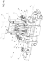
Figure 5 is an enlarged view of a portion of the details ofFigures 3a to 3c andFigures 4a to 4c , with parts removed for clarity; and -
Figure 6a is an enlarged back view of a portion of the detail ofFigures 3a to 3c andFigures 4a to 4c , with parts removed for clarity; -
Figure 6b is an enlarged front view of the portion ofFigure 6a , with parts removed for clarity; and -
Figure 7 is an enlarged perspective view of a further portion of the detail ofFigures 3a to 3c andFigures 4a to 4c , with parts removed for clarity. -
Number 1 indicates as a whole a packaging machine for producing sealedpackages 2 of a pourable product, in particular a pourable food product, such as milk, milk drinks, yoghurt, yoghurt drinks, fruit juice, wine, tomato sauce, emulsions, beverages containing pulp, salt, sugar, etc. - In more detail,
packaging machine 1 may be configured to producepackages 2 from a multilayer packaging material. Preferentially, a multilayer packaging material having heat seal properties (i.e. portions of the multilayer packaging material can be sealed to one another). - In further detail, the multilayer packaging material may comprise at least one layer of fibrous material, such as e.g. paper or cardboard, and at least two layers of heat-seal plastic material, e.g. polyethylene, interposing the layer of fibrous material in between one another. Preferentially, one of these two layers of heat-seal plastic material may define the inner face of
packages 2 contacting the pourable product. - Moreover, the multilayer packaging material may also comprise a layer of gas- and light-barrier material, e.g. aluminum foil or ethylene vinyl alcohol (EVOH) film, preferentially being arranged between one of the layers of the heat-seal plastic material and the layer of fibrous material.
- Preferentially, the packaging material may also comprise a further layer of heat-seal plastic material being interposed between the layer of gas- and light-barrier material and the layer of fibrous material.
- In further detail, the multilayer packaging material may be provided in the form of a
web 3. - Furthermore,
packaging machine 1 may be configured to producepackages 2 by forming a tube 4 fromweb 3, longitudinally sealing tube 4, filling tube 4 with the pourable product and to transversally seal, and preferentially transversally cut tube 4. - According to some possible non-limiting embodiments, each
package 2 may extend along a longitudinal axis A. - According to some possible embodiments, each
package 2 may comprise at least a firsttransversal sealing band 5, and preferentially also a second transversal sealing band arranged at opposite ends ofpackage 2. - Preferentially, each first
transversal sealing band 5 may be substantially spaced apart from the respective second transversal sealing band along the respective longitudinal axis A. - Preferentially, each first
transversal sealing band 5 may define a transversal top sealing band and each second transversal sealing band may define a transversal bottom sealing band. - Moreover, each
package 2 may also comprise alongitudinal seam portion 6. Preferentially, each firsttransversal sealing band 5 and/or each second transversal sealing band may be transversal, preferentially perpendicular, to the respectivelongitudinal seam portion 6. - With particular reference to
Figure 1 ,packaging machine 1 may comprise apackage forming apparatus 10 configured to at least partially form tube 4, preferentially to also transversally seal and/or to transversally cut tube 4, for obtainingpackages 2. - Preferentially,
package forming apparatus 10 may comprise an advancement space within which, in use, tube 4 advances. - Moreover,
packaging machine 1 may also comprise: - a
conveying device 11 configured to advanceweb 3 along a web advancement path P, preferentially to a tube forming station, at which, in use,web 3 is formed into tube 4, and configured to advance tube 4 along a tube advancement path Q; - a tube forming and
sealing device 12 configured to form tube 4 from the, in use, advancingweb 3 and to longitudinally seal tube 4; and - a
filling device 13 for filling tube 4 with the pourable product. - In further detail,
packaging machine 1 may also comprise anisolation chamber 14, preferentially delimiting aninner environment 15 from anouter environment 16. Preferentially,inner environment 15 may be a sterile environment, preferably containing a controlled atmosphere. - Preferentially, tube forming and
sealing device 12 may be at least partially arranged withinisolation chamber 14, in particularinner environment 15, and being configured to fold and longitudinally seal tube 4 withinisolation chamber 14, in particularinner environment 15. - Moreover,
packaging machine 1 may also comprise a sterilization unit configured to sterilize the, in use, advancingweb 3, preferentially the sterilization unit being arranged upstream of tube forming and sealingdevice 12 along web advancement path P. - In more detail,
conveying device 11 may be configured to advance tube 4 and any intermediates of tube 4 along tube advancement path Q, preferentially from tube forming andsealing device 12 to and/or at least partially withinpackage forming apparatus 10. Preferentially, with the wording intermediates of tube 4 any configuration ofweb 3 is meant prior to obtaining the tube structure and after folding ofweb 3 by tube forming andsealing device 12 has started. In other words, the intermediates of tube 4 are a result of the gradual folding ofweb 3 so as to obtain tube 4, preferentially by overlapping the (longitudinal) edges ofweb 3 with one another. - According to some possible non-limiting embodiments, tube forming and
sealing device 12 may be arranged such that tube 4 may have a vertical orientation. - More specifically, tube forming and sealing
device 12 may comprise at least two formingring assemblies 17, preferentially arranged withinisolation chamber 14, even more preferentially arranged withininner environment 15, being configured to gradually fold in cooperation with one anotherweb 3 into tube 4, preferentially by overlapping the edges ofweb 3 with one another. Thereby, in use,seam portion 6 of tube 4 may be formed. - Additionally, tube forming and sealing
device 12 may comprise a sealinghead 18, preferentially arranged withinisolation chamber 14, even more preferentially withininner environment 15, and, configured to longitudinally seal tube 4, preferentially alonglongitudinal seam portion 6. - Moreover, tube forming and sealing
device 12 may also comprise a pressure assembly configured to exert a mechanical force onlongitudinal seam portion 6 to ensure sealing of tube 4 alonglongitudinal seam portion 6. - Preferentially, filling
device 13 may comprise a fillingpipe 19 being configured to direct, in use, the pourable product into tube 4. Preferentially, fillingpipe 19 may, in use, be at least partially placed within tube 4 for feeding, in use, the pourable product into tube 4. - With particular reference to
Figures 2 to 5 ,package forming apparatus 10 may comprise one or more, preferentially a plurality of, operative devices 25 (only partially shown to the extent necessary for the comprehension of the present invention), each one configured to at least partially form, and preferentially to transversally seal and/or transversally cut tube 4. - Preferentially,
package forming apparatus 10 may be configured to control eachoperative device 25 such to at least partially form tube 4 between two spaced transversal cross sections. Additionally,package forming apparatus 10 may transversally seal and transversally cut tube 4 along the equally spaced transversal cross sections, more preferentially thereby forming the respective firsttransversal sealing bands 5 and/or the respective second transversal sealing bands. - According to some possible non-limiting embodiments,
package forming apparatus 10 may comprise at least twooperative devices 25, preferentially exactly two. - In further detail, each
operative device 25 may comprise at least a firstoperative group 26 and a secondoperative group 27 configured to cooperate with one another so as to at least partially form, and preferentially so as to transversally seal and/or transversally cut, tube 4. - In particular, each
first operative group 26 and the respective secondoperative group 27 may be movable with respect to one another, preferentially so as to move eachfirst operative group 26 and the respective secondoperative group 27 towards and away from one another. - In more detail, each
operative device 25 may be controllable between an active configuration, in which the respective firstoperative group 26 and the respective secondoperative group 27 are approached to one another for at least partially forming, and preferentially transversally sealing and/or transversally cutting, tube 4 and a rest configuration, in which the respective firstoperative group 26 and the respective secondoperative group 27 are withdrawn from one another, and preferentially from tube 4. - Moreover,
package forming apparatus 10 may also comprise a conveying unit configured to advance eachfirst operative group 26 and eachsecond operative group 27 along a respective first advancement path and a respective second advancement path, respectively. - In more detail, each first advancement path and each second advancement path may comprise an operative portion along which each
first operative group 26 and the respective secondoperative group 27 advance, in use, in a direction of advancement of tube 4, and a return portion along which eachfirst operative group 26 and eachsecond operative group 27 advance, in use, in a direction opposite to the direction of advancement of tube 4 so as to bring eachfirst operative group 26 and eachsecond operative group 27 back to the respective operative portion. - Moreover, each
operative device 25 may be controlled from the respective rest configuration to the respective active configuration during advancement of the respective firstoperative group 26 and the respective secondoperative group 27 along the respective operative portion, preferentially to at least partially form, and preferentially to at least transversally seal and transversally cut, tube 4. - According to some preferred non-limiting embodiments,
package forming apparatus 10 may comprise one or more actuation units configured to selectively control eachoperative device 25 between the respective active configuration and the respective rest configuration. - According to some preferred non-limiting embodiments,
package forming apparatus 10 may comprise a support structure movably carryingoperative devices 25. - According to some possible embodiments, the support structure may comprise one or more support assemblies, each one movably carrying at least one, preferentially exactly one, respective
operative device 25. Preferentially,package forming apparatus 10 may comprise at least two, preferentially exactly two,operative devices 25, and the support structure may comprise at least two, preferentially exactly two, support assemblies. - Preferentially, support assemblies may be spaced apart from one another thereby defining the advancement space.
- With particular reference to
Figures 2 to 5 , eachfirst operative group 26 and eachsecond operative group 27 comprises a respective half-shell 28 (only shown with respect to second operative group 27) for at least partially forming tube 4 and a respective control device 29 (only shown with respect to second operative group 27) for controlling the respective half-shell 28. - Preferentially, the respective two half-
shells 28 of eachoperative device 25 are configured to at least partially form tube 4 in cooperation with one another, more preferentially with the respectiveoperative device 25 being controlled in the respective active position. - In more detail, the respective two half-
shells 28 of eachoperative device 25 are moved towards one another and withdrawn from one another withoperative device 25 being controlled in the active configuration and the rest configuration, respectively. - Furthermore, with the respective
operative device 25 being controlled in the respective active configuration, the respective two half-shells 28 engage with tube 4 for at least partially forming tube 4. - Preferentially, each
control device 29 may be configured to control the respective half-shell 28 such that therespective packages 2 have a determined volume. - With particular reference to
Figures 3a to 5 , each half-shell 28 comprises a main formingplate 30 and two lateral formingplates 31 interposing main formingplate 30 in between one another. - Each main forming
plate 30 is angularly movable about a first rotation axis B and between a first angular position (seeFigures 3a and4a ) and a second angular position (seeFigures 3c and4c ). In particular, each main formingplate 30 may be positioned in the first angular position and the second angular position with the respectiveoperative device 25 being in the rest configuration and the active configuration, respectively. - Preferentially, each main forming
plate 30 may engage tube 4 when being in the second angular position. - Moreover, each
lateral forming plate 31 is angularly movable about a second rotation axis C transversal, preferentially perpendicular, to the respective first rotation axis B and between a third angular position (seeFigures 3a and4a ) and a fourth angular position (seeFigures 3c and4c ). In particular, eachlateral forming plate 31 may be positioned in the third angular position and the fourth angular position with the respectiveoperative device 25 being in the rest configuration and the active configuration, respectively. - Preferentially, each
lateral forming plate 31 may engage tube 4 when being in the fourth angular position. - Furthermore, each half-shell may be substantially C-shaped with the respective main forming
plate 30 and the respectivelateral forming plates 31 being in the second angular position and the fourth angular positions, respectively. - Each
control device 29 is configure to control, in use, an angular movement of the respective main formingplate 30 from the respective first angular position to the respective second angular position for moving, in use, the respective main formingplate 30 onto tube 4 and a respective angular movement of each respectivelateral forming plate 31 from the respective third angular position to the respective fourth angular position for moving, in use, the respective lateral forming plate onto tube 4. - Moreover, each
control device 29 is configured such to actuate the angular movement of the respective main formingplate 30 from the first angular position to the second angular position and the angular movement of the respectivelateral forming plates 31 from the respective third angular positions to the respective fourth angular positions asynchronously, in particular such that the respective main formingplate 30 gets, in use, in contact with tube 4 prior to the respectivelateral forming plates 31 getting in contact with tube 4 and/or each main formingplate 30 reaches the respective second angular position prior to the respectivelateral forming plates 31 reaching the respective fourth angular positions. - According to some preferred non-limiting embodiments, a respective angular distance of each main forming
plate 30 from the respective first angular position to the respective second angular position may be smaller than a respective angular distance of the respectivelateral forming plates 31 from the respective third angular positions to the respective fourth angular positions. In other words, the angular distance between the first angular position and the second angular position is smaller than the angular distance between the third angular position and the fourth angular position. - With particular reference to
Figures 3a to 5 , eachcontrol device 29 may comprise ashaft 32 rotatable about a third rotation axis E, preferentially parallel to the respective first rotation axis B and/or transversal, more preferentially perpendicular to, the respective second rotation axes C. - Moreover and with particular reference to
Figures 3a to 4c , eachshaft 32 may be operatively coupled to the respective main formingplate 30 and the respectivelateral forming plates 31 such that the angular position of the respective main formingplate 30 about the respective first rotation axis B and of the respectivelateral forming plates 31 about the respective second rotation axes C are determined in dependence of the angular position of therespective shaft 32 about the respective third rotation axis E. -
Figures 3a and4a show a condition in whichshaft 32 is in an angular position about the respective third rotation axis E such that the respective main formingplate 30 is in the respective first angular position and the respectivelateral forming plates 31 are in the respective third angular positions.Figures 3c and4c show a condition in whichshaft 32 is in an angular position about the respective third rotation axis E such that the respective main formingplate 30 is in the respective second angular position and the respectivelateral forming plates 31 are in the respective fourth angular positions. Moreover,Figures 3b and4b illustrate an intermediate condition between the one ofFigures 3a and4a and the one ofFigures 3c and4c . - In other words,
Figures 3a and4a show a configuration of half-shell 28 with the respectiveoperative device 25 being in the rest configuration,Figures 3c and4c show a configuration of half-shell 28 with the respectiveoperative device 25 being in the active configuration andFigures 3b and4b illustrate an intermediate configuration of half-shell 28 during transition between the rest configuration and the active configuration. - According to some preferred non-limiting embodiments, each
shaft 32 may be configured to rotate about the respective third rotation axis E so as to move the respective main formingplate 30 between the respective first angular position and the respective second angular position and the respectivelateral forming plates 31 between the respective third angular positions and the respective fourth angular positions. - In further detail, each
shaft 32 may be rotatable in a first rotation direction so as to move the respective main formingplate 30 from the respective first angular position to the respective second angular position and the respectivelateral forming plates 31 from the respective third angular positions to the respective fourth angular positions. - Additionally, each
shaft 32 may be rotatable in a second rotation direction opposed to the respective first rotation direction so as to move the respective main formingplate 30 from the respective second angular position to the respective first angular position and the respectivelateral forming plates 31 from the respective fourth angular positions to the respective third angular positions. - According to some preferred non-limiting embodiments, each
control device 29 may comprise afirst lever mechanism 33 coupled to therespective shaft 32 and the respective main formingplate 30 and twosecond lever mechanisms 34 each one coupled to therespective shaft 32 and one respectivelateral forming plate 31. - More specifically, each
first lever mechanism 33 and the respectivesecond lever mechanisms 34 may be configured such to actuate an angular movement of, respectively, the respective main formingplate 30 and the respectivelateral forming plate 31, in dependence of an angular movement of therespective shaft 32. - Additionally or alternatively, each
first lever mechanism 33 and the respectivesecond lever mechanisms 34 may be configured to actuate during an angular movement of therespective shaft 32 about the respective third rotation axis E and in the first rotation direction the angular movement of thelateral forming plates 31 from the respective third angular positions to the respective fourth angular positions and of the respective main formingplate 30 from the respective first angular position to the respective second angular position such that the respective main formingplate 30 reaches the second angular position prior to the respectivelateral forming plates 31 reaching the respective fourth angular positions. - More specifically, each
first lever mechanism 33 may comprise at least onecoupling element 35, preferentially twocoupling elements 35 spaced apart from one another and, fixed to therespective shaft 32 and at least onecoupling bar 36, preferentially twocoupling bars 36, hinged to onerespective coupling element 35 and the respective main formingplate 30. - Even more specifically, each
coupling bar 36 may be hinged to therespective coupling element 35 about a respective first hinge axis and may be hinged to the respective main formingplate 30 about a respective second hinge axis. - Preferentially, each first hinge axis and the respective second hinge axis may be parallel to one another.
- Alternatively or in addition, each first hinge axis and the respective second hinge axis may be parallel to the respective first rotation axis B and/or the respective third rotation axis E.
- According to some preferred non-limiting embodiments, each
second lever mechanism 34 may comprises a first connectingelement 40 connected to therespective shaft 32, a second connectingelement 41 connected to the respectivelateral forming plate 31 and acoupling mechanism 42 coupled to the respective first connectingelement 40 and the respective second connectingelement 41. - With particular reference to
Figure 7 , eachcoupling mechanism 42 may comprise a balljoint assembly 43. - In more detail, each ball
joint assembly 43 may comprise a first balljoint group 44 coupled to the respective first connectingelement 40 and a second balljoint group 45 coupled to the respective second connectingelement 41. - Preferentially, each first ball
joint group 44 may be connected to, more preferentially fixed to, the respective second balljoint group 45. - In even more detail, each first ball
joint group 44 may comprise afirst ball element 46 connected to the respective first connectingelement 40 and afirst element 47 movably arranged about thefirst ball element 46. - Additionally, each second ball
joint group 45 may comprise asecond ball element 48 connected to the respective second connectingelement 41 and asecond element 49 movably arranged about thesecond ball element 48. - Preferentially, each
first element 47 and the respectivesecond element 49 may be connected to, preferentially fixed to, one another. - With particular reference to
Figures 6a and6b , eachfirst operative group 26 and eachsecond operative group 27 may comprise arespective support 50 rotatably carrying therespective shaft 32, in particular such that therespective shaft 32 is rotatable about the respective third rotation axis E. - Additionally, each main forming
plate 30 may be hinged to therespective support 50 and about the respective first rotation axis B. - Moreover, each
lateral forming plate 31 may be hinged to therespective support 50 and about the respective second rotation axis C. - According to some preferred non-limiting embodiments, package forming apparatus may comprise an actuating device configured to control operation of each control device so as to control the angular position of the respective main forming
plate 30 and of the respective angular positions of the respectivelateral forming plates 31. - Preferentially, the actuating device may be configured to control the angular position of
shafts 32. - Even more preferentially, the actuating device may be configured to control the respective angular position of
shafts 32 in dependence of the respective position of the respective firstoperative group 26 and the respective secondoperative group 27 along the respective advancement path. - With particular reference to
Figures 2 to 5 , eachoperative device 25 may comprise arespective sealing element 55 and a respectivecounter-sealing element 56 configured to transversally seal in cooperation with one another tube 4. - According to some preferred non-limiting embodiments, one of each
first operative group 26 and the respective secondoperative group 27 may comprise therespective sealing element 47 and the other one of eachfirst operative group 26 and the respective secondoperative group 27 may comprise the respectivecounter-sealing element 56. - More specifically, each sealing
element 55 and the respectivecounter-sealing element 56 may be configured to at least transversally compress, in particular flat-lay and squeeze, and to transversally seal tube 4, in particular during advancement of tube 4 along tube advancement path Q. - Moreover, each sealing
element 55 and the respectivecounter-sealing element 56 may be configured to engage tube 4 from opposite sides thereof. - In further detail, each sealing
element 55 may comprise a source configured to generate the energy needed to obtain the sealing effect. For example, sealingelement 55 may be a sonotrode having ultrasound-emitters or sealingelement 55 may have an electromagnetic induction source. Eachcounter-sealing element 56 may be a passive element (i.e. not having an active source). For examplecounter-sealing element 56 may be a metal anvil or a deformable pad. - Additionally, each
operative device 25 may comprise at least one cutting element configured to transversally cut tube 4. Preferentially, each cutting element may be configured to transversally cut tube 4 after sealing of tube 4 by means of the respective sealing assembly. - Each cutting element may be associated with one of the respective first
operative group 26 and the respective secondoperative group 27. - With particular reference to
Figures 3a to 3c , eachoperative device 25, preferentially one of the respective firstoperative group 26 and the respective secondoperative group 27, may comprise a pair ofmovable interaction tabs 57 configured to interact, in use, with tube 4 from opposite sides thereof. - In use,
packaging machine 1 producespackages 2 filled with the pourable product. - In more detail, conveying
device 11 advancesweb 3 along web advancement path P. Tube forming and sealingdevice 12 forms tube 4 from the advancingweb 3 and longitudinally seals tube 4. Additionally, fillingdevice 13 fills tube 4 with the pourable product andpackage forming apparatus 10 forms, transversally seals and transversally cuts tube 4 so as to obtainpackages 2. - In further detail, during operation of
package forming apparatus 10,operative devices 25 at least partially form, and preferentially transversally seal and transversally cut, tube 4. - During operation, each
operative device 25 is cyclically controlled between the respective rest configuration and the respective active configuration. - Preferentially, the respective first
operative groups 26 and the respective secondoperative groups 27 advance along the respective advancement paths and are cyclically moved towards and away from one another so as to at least partially form, transversally seal and cut tube 4 for formingpackages 2. - The partial forming of tube 4 is controlled by the respective half-
shells 28. In order to partially form tube 4, the respective main formingplates 30 are moved from the respective first angular position to the respective second angular position, and the respectivelateral forming plates 31 are moved from the respective third angular position to the respective fourth angular position, preferentially by controlling the respective angular position of therespective shaft 32. In particular, thereby the respective main formingplate 30 and the respectivelateral forming plates 31 move asynchronously. - The advantages of
package forming apparatus 10 and/orpackaging machine 1 according to the present invention will be clear from the foregoing description. - In particular, the asynchronous movement of main forming
plates 30 with respect to the respectivelateral forming plates 31 allows to precisely control the volume ofpackages 2 by means of controlling the movement oflateral forming plates 31. - Clearly, changes may be made to package forming
apparatus 10 and/orpackaging machine 1 as described herein without, however, departing from the scope of protection as defined in the accompanying claims.
Claims (15)
- Package forming apparatus (10) for a packaging machine (1) and configured to at least partially form a tube (4) for obtaining packages (2) from the tube (4);wherein the package forming apparatus (10) comprises at least one operative device (25) having a first operative group (26) and a second operative group (27) configured to at least partially form in cooperation with one another the tube (4) for forming the packages (2);wherein each first operative group (26) and each second operative group (27) comprises a respective half-shell (28) for at least partially forming the tube (4) and a respective control device (29) for controlling the respective half-shell (28);wherein each half-shell (28) comprises a main forming plate (30) and two lateral forming plates (31) interposing the main forming plate (30) in between one another;wherein each main forming plate (30) is angularly movable about a first rotation axis (B) and between a first angular position and a second angular position;wherein each lateral forming plate (31) is angularly movable about a second rotation axis (C) transversal to the respective first rotation axis (B) and between a third angular position and a fourth angular position;wherein each control device (29) is configured to control, in use, an angular movement of the respective main forming plate (30) from the respective first angular position to the respective second angular position for moving, in use, the respective main forming plate (30) onto the tube (4) and a respective angular movement of each respective lateral forming plate (31) from the respective third angular position to the respective fourth angular position for moving, in use, the respective lateral forming plate onto the tube (4);wherein each control device (29) is configured such to actuate the angular movement of the respective main forming plate (30) from the first angular position to the second angular position and the angular movement of the respective lateral forming plates (31) from the respective third angular positions to the respective fourth angular positions asynchronously.
- Package forming apparatus according to claim 1, wherein each control device (29) is configured such to actuate the angular movement of the respective main forming plate from the first angular position to the second angular position and the angular movement of the respective lateral forming plates (31) from the respective third angular positions to the respective fourth angular positions such that the main forming plate (30) gets, in use, in contact with the tube (4) prior to the respective lateral forming plates (30) getting in contact with the tube (4) and/or each main forming plate (30) reaches the respective second angular position prior to the respective lateral forming plates (31) reaching the respective fourth angular position; and/or
a respective angular distance of each main forming plate (30) from the respective first angular position to the respective second angular position is smaller than a respective angular distance of the respective lateral forming plates (31) from the respective third angular position to the respective fourth angular position. - Package forming apparatus according to claim 1 or 2, wherein each control device (29) comprises a shaft (32) rotatable about a third rotation axis (E) and being operatively coupled to the respective main forming plate (30) and the respective lateral forming plates (31);
wherein the angular position of each main forming plate (30) about the respective first rotation axis (B) and of each lateral forming plate (31) about the respective second rotation axis (C) is determined in dependence of the angular position of the respective shaft (32) about the respective third rotation axis (E). - Package forming apparatus according to claim 3, wherein each shaft (32) is configured to rotate about the third rotation axis (E) so as to move the respective main forming plate (30) between the respective first angular position and the respective second angular position and the respective lateral forming plates (31) between the respective third angular positions and the respective fourth angular positions.
- Package forming apparatus according to claim 4, wherein each control device (29) comprises a first lever mechanism (33) coupled to the shaft (32) and the respective main forming plate (30) and two second lever mechanisms (34) each one coupled to the shaft (32) and one respective lateral forming plate (31);wherein each first lever mechanism (33) and the respective second lever mechanisms (34) are configured such to actuate an angular movement of, respectively, the respective main forming plate (30) and the respective lateral forming plates (31) in dependence of an angular movement of the respective shaft (32) about the third rotation axis (E); and/orwherein each first lever mechanism (33) and the respective second lever mechanisms (34) are configured to actuate during an angular movement of the shaft (32) about the third rotation axis (E) and in a first rotation direction the angular movement of the lateral forming plates (31) from the respective third angular positions to the respective fourth angular positions and of the respective main forming plate (30) from the respective first angular position to the respective second angular position such that the respective main forming plate (30) reaches the second angular position prior to the respective lateral forming plates (31) reaching the respective fourth angular positions.
- Package forming apparatus according to claim 5, wherein each first lever mechanism (33) comprises a coupling element (35) fixed to the respective shaft (32) and a coupling bar (36) hinged to the coupling element (35) and the respective main forming plate (30).
- Package forming apparatus according to claim 6, wherein each coupling bar (36) is hinged to the respective coupling element (35) about a first hinge axis and is hinged to the respective main forming plate (30) about a second hinge axis;wherein each first hinge axis and the respective second hinge axis are parallel to one another; and/oreach first hinge axis and/or the respective second hinge axis are parallel to the respective third rotation axis (E) and/or the respective first rotation axis (B).
- Package forming apparatus according to any one of claims 5 to 7, wherein each second lever mechanism (34) comprises a first connecting element (40) connected to the shaft (32), a second connecting element (41) connected to the respective lateral forming plate (31) and a coupling mechanism (42) coupled to the first connecting element (40) and the second connecting element (41).
- Package forming apparatus according to claim 8, wherein each coupling mechanism (42) comprises a ball joint assembly (43).
- Package forming apparatus according to claim 9, wherein each ball joint assembly (43) comprises a first ball joint group (44) coupled to the first connecting element (40) and a second ball joint group (45) coupled to the second connecting element (41);
wherein each first ball joint group (44) is connected to the respective second ball joint group (45). - Package forming apparatus according to claim 10, wherein each first ball joint group (44) comprises a first ball element (46) connected to the respective first connecting element (40) and a first element (47) movably arranged about the first ball element (46) and the respective second ball joint group (45) comprises a second ball element (48) connected to the respective second connecting element (41) and a second element (49) movably arranged about the second ball element (48);
wherein each first element (47) and the respective second element (49) are connected to one another. - Package forming apparatus according to any one of claim 3 to 11, wherein each first operative group (26) and each second operative group (27) comprises a respective support (50) rotatably carrying the respective shaft (32);wherein the respective main forming plate (30) is hinged to the respective support (50) and about the respective first rotation axis (B); andwherein the respective lateral forming plates (31) are hinged to the respective support (50) and about the respective second rotation axis (C).
- Package forming apparatus according to any one of the preceding claims, and further comprising an actuating device for controlling operation of each control device so as to control the angular position of the respective main forming plate (30) and the respective angular positions of the respective lateral forming plates (31).
- Package forming apparatus according to any one of the preceding claims, wherein each operative device (25) is controllable between an active configuration, in which the respective half-shell of the first operative group (26) and the respective half-shell of the second operative group (27) are approached to one another for at least partially forming the tube (4) and a rest configuration, in which the respective half-shell of the respective first operative group (26) and the respective half-shell of the respective second operative group (27) are withdrawn from one another;wherein each main forming plate (30) is positioned in the respective second angular position and the respective lateral forming plates (31) are positioned in the respective fourth angular positions with the respective operative device (25) being controlled in the active configuration; andwherein each main forming plate (30) is positioned in the respective first angular position and the respective lateral forming plates are positioned in the respective third angular positions with the respective operative device (25) being controlled in the rest configuration.
- Packaging machine (1) for forming packages (2) of a pourable product from an advancing tube (4) formed and longitudinally sealed from a web of packaging material (4);
the packaging machine (1) comprises:- a conveying device (11) configured to advance the web of packaging material (3) along a web advancement path (P) and for advancing the tube (4) along a tube advancement path (Q) ;- a tube forming and sealing device (12) configured to form the tube (4) from the web of packaging material (3) and to longitudinally seal the tube (4);- a filling device (13) for filling the tube (4) with the pourable product; and- a package forming apparatus (10) according to any one of the preceding claims.
Applications Claiming Priority (1)
| Application Number | Priority Date | Filing Date | Title |
|---|---|---|---|
| IT102023000001557A IT202300001557A1 (en) | 2023-02-01 | 2023-02-01 | APPARATUS FOR FORMING PACKAGES FOR A PACKAGING MACHINE AND PACKAGING MACHINE FOR FORMING PACKAGES FILLED WITH A POURABLE PRODUCT |
Publications (2)
| Publication Number | Publication Date |
|---|---|
| EP4410690A1 true EP4410690A1 (en) | 2024-08-07 |
| EP4410690B1 EP4410690B1 (en) | 2025-11-05 |
Family
ID=85791964
Family Applications (1)
| Application Number | Title | Priority Date | Filing Date |
|---|---|---|---|
| EP24153888.3A Active EP4410690B1 (en) | 2023-02-01 | 2024-01-25 | Package forming apparatus for a packaging machine and packaging machine for forming packages filled with a pourable product |
Country Status (5)
| Country | Link |
|---|---|
| EP (1) | EP4410690B1 (en) |
| JP (1) | JP2026504026A (en) |
| CN (1) | CN120641326A (en) |
| IT (1) | IT202300001557A1 (en) |
| WO (1) | WO2024160634A1 (en) |
Citations (2)
| Publication number | Priority date | Publication date | Assignee | Title |
|---|---|---|---|---|
| US3325961A (en) * | 1963-01-16 | 1967-06-20 | Tetra Pak Ab | Method and a device for manufacturing filled and sealed packages |
| WO2009040435A1 (en) * | 2007-09-28 | 2009-04-02 | Tetra Laval Holdings & Finance S.A. | Member and method for forming sealed packages of pourable food products from a tube of packaging material |
-
2023
- 2023-02-01 IT IT102023000001557A patent/IT202300001557A1/en unknown
-
2024
- 2024-01-25 CN CN202480010582.3A patent/CN120641326A/en active Pending
- 2024-01-25 JP JP2025540117A patent/JP2026504026A/en active Pending
- 2024-01-25 EP EP24153888.3A patent/EP4410690B1/en active Active
- 2024-01-25 WO PCT/EP2024/051730 patent/WO2024160634A1/en not_active Ceased
Patent Citations (2)
| Publication number | Priority date | Publication date | Assignee | Title |
|---|---|---|---|---|
| US3325961A (en) * | 1963-01-16 | 1967-06-20 | Tetra Pak Ab | Method and a device for manufacturing filled and sealed packages |
| WO2009040435A1 (en) * | 2007-09-28 | 2009-04-02 | Tetra Laval Holdings & Finance S.A. | Member and method for forming sealed packages of pourable food products from a tube of packaging material |
Also Published As
| Publication number | Publication date |
|---|---|
| IT202300001557A1 (en) | 2024-08-01 |
| JP2026504026A (en) | 2026-02-03 |
| WO2024160634A1 (en) | 2024-08-08 |
| EP4410690B1 (en) | 2025-11-05 |
| CN120641326A (en) | 2025-09-12 |
Similar Documents
| Publication | Publication Date | Title |
|---|---|---|
| US10773846B2 (en) | Anvil for transversally sealing a tube of packaging material and sealing jaw having an anvil | |
| EP3943400B1 (en) | Package forming unit, packaging apparatus having a package forming unit and method for forming packages | |
| EP4410690B1 (en) | Package forming apparatus for a packaging machine and packaging machine for forming packages filled with a pourable product | |
| EP4549329A1 (en) | Package forming apparatus for a packaging machine and packaging machine for forming packages filled with a pourable product | |
| EP4410692A1 (en) | Package forming apparatus for a packaging machine and packaging machine for forming packages filled with a pourable product | |
| EP4410523B1 (en) | Package forming apparatus for a packaging machine and packaging machine for forming packages filled with a pourable product | |
| EP4410522B1 (en) | Package forming apparatus for a packaging machine and packaging machine for forming packages filled with a pourable product | |
| EP4410691B1 (en) | Package forming apparatus for a packaging machine and packaging machine for forming packages filled with a pourable product | |
| EP4410524A1 (en) | Package forming apparatus for a packaging machine and packaging machine for forming packages filled with a pourable product | |
| EP4410520B1 (en) | Package forming apparatus for a packaging machine and packaging machine for forming packages filled with a pourable product | |
| EP4454864A1 (en) | Package forming apparatus for a packaging machine and packaging machine for forming packages filled with a pourable product | |
| EP4458689A1 (en) | Package forming apparatus for a packaging machine, packaging machine for forming packages filled with a pourable product and method for forming packages | |
| EP4474299A1 (en) | Package forming apparatus and packaging machine for forming packages | |
| EP4717444A1 (en) | Sealing anvil device, sealing device, package forming apparatus for a packaging machine and packaging machine for forming packages filled with a pourable product | |
| EP4588646A1 (en) | Apparatus for applying a sealing strip of a heat-sealable material to a web of packaging material and packaging machine for forming sealed packages |
Legal Events
| Date | Code | Title | Description |
|---|---|---|---|
| PUAI | Public reference made under article 153(3) epc to a published international application that has entered the european phase |
Free format text: ORIGINAL CODE: 0009012 |
|
| STAA | Information on the status of an ep patent application or granted ep patent |
Free format text: STATUS: THE APPLICATION HAS BEEN PUBLISHED |
|
| AK | Designated contracting states |
Kind code of ref document: A1 Designated state(s): AL AT BE BG CH CY CZ DE DK EE ES FI FR GB GR HR HU IE IS IT LI LT LU LV MC ME MK MT NL NO PL PT RO RS SE SI SK SM TR |
|
| STAA | Information on the status of an ep patent application or granted ep patent |
Free format text: STATUS: REQUEST FOR EXAMINATION WAS MADE |
|
| 17P | Request for examination filed |
Effective date: 20250207 |
|
| GRAP | Despatch of communication of intention to grant a patent |
Free format text: ORIGINAL CODE: EPIDOSNIGR1 |
|
| STAA | Information on the status of an ep patent application or granted ep patent |
Free format text: STATUS: GRANT OF PATENT IS INTENDED |
|
| INTG | Intention to grant announced |
Effective date: 20250708 |
|
| GRAJ | Information related to disapproval of communication of intention to grant by the applicant or resumption of examination proceedings by the epo deleted |
Free format text: ORIGINAL CODE: EPIDOSDIGR1 |
|
| STAA | Information on the status of an ep patent application or granted ep patent |
Free format text: STATUS: REQUEST FOR EXAMINATION WAS MADE |
|
| GRAP | Despatch of communication of intention to grant a patent |
Free format text: ORIGINAL CODE: EPIDOSNIGR1 |
|
| STAA | Information on the status of an ep patent application or granted ep patent |
Free format text: STATUS: GRANT OF PATENT IS INTENDED |
|
| GRAJ | Information related to disapproval of communication of intention to grant by the applicant or resumption of examination proceedings by the epo deleted |
Free format text: ORIGINAL CODE: EPIDOSDIGR1 |
|
| STAA | Information on the status of an ep patent application or granted ep patent |
Free format text: STATUS: REQUEST FOR EXAMINATION WAS MADE |
|
| GRAP | Despatch of communication of intention to grant a patent |
Free format text: ORIGINAL CODE: EPIDOSNIGR1 |
|
| STAA | Information on the status of an ep patent application or granted ep patent |
Free format text: STATUS: GRANT OF PATENT IS INTENDED |
|
| INTC | Intention to grant announced (deleted) | ||
| GRAS | Grant fee paid |
Free format text: ORIGINAL CODE: EPIDOSNIGR3 |
|
| GRAA | (expected) grant |
Free format text: ORIGINAL CODE: 0009210 |
|
| STAA | Information on the status of an ep patent application or granted ep patent |
Free format text: STATUS: THE PATENT HAS BEEN GRANTED |
|
| INTG | Intention to grant announced |
Effective date: 20250908 |
|
| INTC | Intention to grant announced (deleted) | ||
| INTG | Intention to grant announced |
Effective date: 20250923 |
|
| AK | Designated contracting states |
Kind code of ref document: B1 Designated state(s): AL AT BE BG CH CY CZ DE DK EE ES FI FR GB GR HR HU IE IS IT LI LT LU LV MC ME MK MT NL NO PL PT RO RS SE SI SK SM TR |
|
| REG | Reference to a national code |
Ref country code: CH Ref legal event code: F10 Free format text: ST27 STATUS EVENT CODE: U-0-0-F10-F00 (AS PROVIDED BY THE NATIONAL OFFICE) Effective date: 20251105 Ref country code: GB Ref legal event code: FG4D |
|
| REG | Reference to a national code |
Ref country code: DE Ref legal event code: R096 Ref document number: 602024001111 Country of ref document: DE |
|
| REG | Reference to a national code |
Ref country code: IE Ref legal event code: FG4D |
|
| REG | Reference to a national code |
Ref country code: NL Ref legal event code: MP Effective date: 20251105 |
|
| PG25 | Lapsed in a contracting state [announced via postgrant information from national office to epo] |
Ref country code: ES Free format text: LAPSE BECAUSE OF FAILURE TO SUBMIT A TRANSLATION OF THE DESCRIPTION OR TO PAY THE FEE WITHIN THE PRESCRIBED TIME-LIMIT Effective date: 20251105 |
|
| REG | Reference to a national code |
Ref country code: LT Ref legal event code: MG9D |
|
| PG25 | Lapsed in a contracting state [announced via postgrant information from national office to epo] |
Ref country code: NO Free format text: LAPSE BECAUSE OF FAILURE TO SUBMIT A TRANSLATION OF THE DESCRIPTION OR TO PAY THE FEE WITHIN THE PRESCRIBED TIME-LIMIT Effective date: 20260205 |
|
| PGFP | Annual fee paid to national office [announced via postgrant information from national office to epo] |
Ref country code: DE Payment date: 20260127 Year of fee payment: 3 |
|
| PG25 | Lapsed in a contracting state [announced via postgrant information from national office to epo] |
Ref country code: FI Free format text: LAPSE BECAUSE OF FAILURE TO SUBMIT A TRANSLATION OF THE DESCRIPTION OR TO PAY THE FEE WITHIN THE PRESCRIBED TIME-LIMIT Effective date: 20251105 Ref country code: HR Free format text: LAPSE BECAUSE OF FAILURE TO SUBMIT A TRANSLATION OF THE DESCRIPTION OR TO PAY THE FEE WITHIN THE PRESCRIBED TIME-LIMIT Effective date: 20251105 Ref country code: AT Free format text: LAPSE BECAUSE OF FAILURE TO SUBMIT A TRANSLATION OF THE DESCRIPTION OR TO PAY THE FEE WITHIN THE PRESCRIBED TIME-LIMIT Effective date: 20251105 |
|
| PGFP | Annual fee paid to national office [announced via postgrant information from national office to epo] |
Ref country code: AT Payment date: 20260301 Year of fee payment: 3 |
|
| PGFP | Annual fee paid to national office [announced via postgrant information from national office to epo] |
Ref country code: IT Payment date: 20260131 Year of fee payment: 3 |
|
| REG | Reference to a national code |
Ref country code: AT Ref legal event code: MK05 Ref document number: 1854139 Country of ref document: AT Kind code of ref document: T Effective date: 20251105 |
|
| PG25 | Lapsed in a contracting state [announced via postgrant information from national office to epo] |
Ref country code: NL Free format text: LAPSE BECAUSE OF FAILURE TO SUBMIT A TRANSLATION OF THE DESCRIPTION OR TO PAY THE FEE WITHIN THE PRESCRIBED TIME-LIMIT Effective date: 20251105 |
|
| PG25 | Lapsed in a contracting state [announced via postgrant information from national office to epo] |
Ref country code: RS Free format text: LAPSE BECAUSE OF FAILURE TO SUBMIT A TRANSLATION OF THE DESCRIPTION OR TO PAY THE FEE WITHIN THE PRESCRIBED TIME-LIMIT Effective date: 20260205 |
|
| PG25 | Lapsed in a contracting state [announced via postgrant information from national office to epo] |
Ref country code: IS Free format text: LAPSE BECAUSE OF FAILURE TO SUBMIT A TRANSLATION OF THE DESCRIPTION OR TO PAY THE FEE WITHIN THE PRESCRIBED TIME-LIMIT Effective date: 20260305 |
|
| PG25 | Lapsed in a contracting state [announced via postgrant information from national office to epo] |
Ref country code: PT Free format text: LAPSE BECAUSE OF FAILURE TO SUBMIT A TRANSLATION OF THE DESCRIPTION OR TO PAY THE FEE WITHIN THE PRESCRIBED TIME-LIMIT Effective date: 20260305 |
|
| PG25 | Lapsed in a contracting state [announced via postgrant information from national office to epo] |
Ref country code: PL Free format text: LAPSE BECAUSE OF FAILURE TO SUBMIT A TRANSLATION OF THE DESCRIPTION OR TO PAY THE FEE WITHIN THE PRESCRIBED TIME-LIMIT Effective date: 20251105 |
|
| PG25 | Lapsed in a contracting state [announced via postgrant information from national office to epo] |
Ref country code: LV Free format text: LAPSE BECAUSE OF FAILURE TO SUBMIT A TRANSLATION OF THE DESCRIPTION OR TO PAY THE FEE WITHIN THE PRESCRIBED TIME-LIMIT Effective date: 20251105 |
|
| PG25 | Lapsed in a contracting state [announced via postgrant information from national office to epo] |
Ref country code: BG Free format text: LAPSE BECAUSE OF FAILURE TO SUBMIT A TRANSLATION OF THE DESCRIPTION OR TO PAY THE FEE WITHIN THE PRESCRIBED TIME-LIMIT Effective date: 20251105 |