EP4410683A1 - Method and system for monitoring operations of landing gears of aircrafts - Google Patents
Method and system for monitoring operations of landing gears of aircrafts Download PDFInfo
- Publication number
- EP4410683A1 EP4410683A1 EP23305125.9A EP23305125A EP4410683A1 EP 4410683 A1 EP4410683 A1 EP 4410683A1 EP 23305125 A EP23305125 A EP 23305125A EP 4410683 A1 EP4410683 A1 EP 4410683A1
- Authority
- EP
- European Patent Office
- Prior art keywords
- landing gear
- monitored
- operational state
- aircraft
- captured
- Prior art date
- Legal status (The legal status is an assumption and is not a legal conclusion. Google has not performed a legal analysis and makes no representation as to the accuracy of the status listed.)
- Granted
Links
Images


Classifications
-
- B—PERFORMING OPERATIONS; TRANSPORTING
- B64—AIRCRAFT; AVIATION; COSMONAUTICS
- B64D—EQUIPMENT FOR FITTING IN OR TO AIRCRAFT; FLIGHT SUITS; PARACHUTES; ARRANGEMENT OR MOUNTING OF POWER PLANTS OR PROPULSION TRANSMISSIONS IN AIRCRAFT
- B64D45/00—Aircraft indicators or protectors not otherwise provided for
- B64D45/0005—Devices specially adapted to indicate the position of a movable element of the aircraft, e.g. landing gear
-
- B—PERFORMING OPERATIONS; TRANSPORTING
- B64—AIRCRAFT; AVIATION; COSMONAUTICS
- B64C—AEROPLANES; HELICOPTERS
- B64C25/00—Alighting gear
-
- B—PERFORMING OPERATIONS; TRANSPORTING
- B64—AIRCRAFT; AVIATION; COSMONAUTICS
- B64F—GROUND OR AIRCRAFT-CARRIER-DECK INSTALLATIONS SPECIALLY ADAPTED FOR USE IN CONNECTION WITH AIRCRAFT; DESIGNING, MANUFACTURING, ASSEMBLING, CLEANING, MAINTAINING OR REPAIRING AIRCRAFT, NOT OTHERWISE PROVIDED FOR; HANDLING, TRANSPORTING, TESTING OR INSPECTING AIRCRAFT COMPONENTS, NOT OTHERWISE PROVIDED FOR
- B64F5/00—Designing, manufacturing, assembling, cleaning, maintaining or repairing aircraft, not otherwise provided for; Handling, transporting, testing or inspecting aircraft components, not otherwise provided for
- B64F5/40—Maintaining or repairing aircraft
-
- G—PHYSICS
- G06—COMPUTING OR CALCULATING; COUNTING
- G06N—COMPUTING ARRANGEMENTS BASED ON SPECIFIC COMPUTATIONAL MODELS
- G06N20/00—Machine learning
-
- G—PHYSICS
- G06—COMPUTING OR CALCULATING; COUNTING
- G06T—IMAGE DATA PROCESSING OR GENERATION, IN GENERAL
- G06T7/00—Image analysis
- G06T7/70—Determining position or orientation of objects or cameras
- G06T7/73—Determining position or orientation of objects or cameras using feature-based methods
- G06T7/74—Determining position or orientation of objects or cameras using feature-based methods involving reference images or patches
-
- G—PHYSICS
- G06—COMPUTING OR CALCULATING; COUNTING
- G06T—IMAGE DATA PROCESSING OR GENERATION, IN GENERAL
- G06T2207/00—Indexing scheme for image analysis or image enhancement
- G06T2207/20—Special algorithmic details
- G06T2207/20081—Training; Learning
-
- G—PHYSICS
- G06—COMPUTING OR CALCULATING; COUNTING
- G06T—IMAGE DATA PROCESSING OR GENERATION, IN GENERAL
- G06T2207/00—Indexing scheme for image analysis or image enhancement
- G06T2207/30—Subject of image; Context of image processing
- G06T2207/30248—Vehicle exterior or interior
- G06T2207/30252—Vehicle exterior; Vicinity of vehicle
Definitions
- the present invention relates to the field of monitoring operations of landing gears of aircrafts.
- Landing gears of aircrafts are currently monitored using numerous sensors.
- Proximity sensors positioned at various locations in the landing gear vicinity make it possible to detect the actual position, or operating state, of the landing gear, and thus to check in particular that the release, deployment, retraction, locking in the up position and locking in the down position are properly working.
- these various sensors require regular servicing and maintenance operations to ensure reliability of the landing gear.
- a method for providing an operational state of a monitored landing gear of an aircraft comprising: obtaining in real-time captured signals representative of an actual position of the monitored landing gear; transforming the captured signals in a descriptor vector using Principal Components Analysis; injecting the descriptor vector in a machine learning-based model trained and configured to transform descriptor vectors into equivalent operational states of landing gears; and providing the operational state of the monitored landing gear.
- the operational state of the monitored landing gear of the aircraft can easily be provided without having recourse to numerous sensors. Servicing and maintenance operations are therefore simplified.
- the captured signals are captured images.
- the images are captured by at least one video camera placed in the aircraft in the vicinity of the monitored landing gear, in such a way to capture images of the monitored landing gear, whatever is the operational state of the monitored landing gear during operations.
- candidate operational states of landing gears are: up-locked, up-unlocked, in-transit, down-unlocked, and down-locked.
- the operational state of the monitored landing gear is provided to avionics of the aircraft.
- a computer program product comprising instructions causing execution, by a processor, of the method above in any one of its embodiments, when said instructions are executed by the processor. It is further disclosed herein a non-transitory storage medium storing instructions causing execution, by a processor, of the method above in any one of its embodiments, when said instructions are read from the non-transitory storage medium and executed by the processor.
- the method beforehand comprises initializing the model by a computer system, as follows: obtaining a set of reference signals of candidate operational states of landing gears; generating, in un-supervised mode, a codebook of using Principal Components Analysis on the set of reference signals, the codebook gathering descriptor vectors obtained from the set of reference signals using Principal Components Analysis; building the machine learning-based model, in supervised mode, for labelling descriptor vectors with information representative of a corresponding operational state of landing gears.
- the set of reference signals is a set of reference images consisting of a plurality of images of each candidate operational state, captured with different lighting conditions and/or with different background interference.
- a system for providing an operational state of a monitored landing gear of an aircraft comprising electronic circuitry configured for implementing: obtaining in real-time captured signals of the monitored landing gear; transforming the captured signals in a descriptor vector using Principal Components Analysis; injecting the descriptor vector in a machine learning-based model trained and configured to transform descriptor vectors into equivalent operational states of landing gears; and providing the operational state of the monitored landing gear.
- an aircraft comprising the system above so as to monitor operations of at least one landing gear of the aircraft.
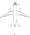
- Fig. 1 schematically illustrates, in top view, an aircraft 10.
- the aircraft 10 comprises avionics 100.
- the avionics 100 include a control device 101 of a system 200 for monitoring operation of at least one landing gear of the aircraft 10.
- the control device 101 may be located elsewhere in the aircraft 10, for example nearby each landing gear that is monitored by said system.
- the control device 101 is in communication with the avionics 100, for example using a dedicated wiring or using a shared communication bus, so as to report in real-time an operational state of each landing gear that is monitored by said system.
- candidate operational states of the landing gear are: up-locked, up-unlocked, in-transit, down-unlocked, and down-locked.
- Other candidate operational states may be added, more particularly to divide the in-transit state into refined substates.
- the system 200 for monitoring operation of at least one landing gear of the aircraft 10 comprises at least one capturing device adapted and configured to capture in real-time signals representative of an actual position of the landing gear, whatever is the operational state of the landing gear in question during operations.
- the signals captured by the at least one capturing device are thus representative of the operational state of the landing gear in question.
- the capturing device is a video camera.
- the system 200 for monitoring operation of at least one landing gear of the aircraft 10 thus comprises at least one video camera.
- Fig. 2 illustratively shows two video cameras CAM1 201 and CAM2 202.
- the at least one video camera CAM1 201, CAM2 202 are placed in the aircraft in the vicinity of the landing gear to be monitored, in such a way to capture images of the landing gear in question, whatever is the operational state of the landing gear in question during operations.
- the images captured by the at least one video camera CAM1 201, CAM2 202 are thus representative of the operational state of the landing gear in question.
- the capturing device is a LIDAR ("light detection and ranging” or “laser imaging detection and ranging”) device.
- the light signals captured by the at least one LIDAR device are thus representative of the operational state of the landing gear in question.
- Signals captured by the at least one capturing device are transmitted, for example using dedicated wiring or using wireless communications, to the control device 101 for further analysis thereof.
- images captured by the at least one video camera CAM1 201, CAM2 202 are transmitted to the control device 101 for further analysis thereof.
- the control device 101 comprises an analyzer 251 configured for performing Principal Components Analysis (PCA) on signals captured by the at least one capturing device, such as the images captured by the at least one video camera CAM1 201, CAM2 202.
- PCA Principal Components Analysis
- PCA is a statistical method for reducing dimensionality of a dataset by linearly transforming input data into a new coordinate system where the most meaningful part of data variation can be expressed with fewer dimensions.
- PCA is thus a process of computing principal components of a dataset and using said principal components to perform a change of basis.
- the first (most) principal component of a set of N original variables is a derived variable that is a linear combination of the N original variables and that exposes the most variance.
- the second principal component is a derived variable that is a linear combination of the N original variables and that exposes the most variance in what is left once the effect of the first principal component is removed. N iterations can thus be performed until all the variance is considered, even though fewer iterations are typically used when dimensionality reduction is targeted.
- the quantity of iterations to be performed is context dependent and can be defined by experiments, depending on targeted accuracy of data analysis. Using PCA on signals such as video images or LIDAR signals is particularly advantageous since such signals are highly correlated, which enables
- PCA is a dimensionality reduction technique that successively includes: feature covariance computation, eigen-decomposition, principal component transformation, and principal components selection.
- the principal components are determined by calculating the eigenvectors and eigenvalues of the input data covariance matrix. Once eigenvectors are found from the covariance matrix, the eigenvectors are ordered by eigenvalue, in descending order. It provides the principal components listed according to their significance. Principle components selection is performed in descending order of significance so as to form a descriptor vector.
- the signals 261 output by the at least one capturing device such as the images received from the at least one video camera CAM1 201, CAM2 202, are input to the analyzer 251, which processes said input signals 261 according to PCA principles, so as to provide the descriptor vector 262 (also referred to as feature vector), which is therefore reduced in terms of dimensionality compared with the input signals 261.
- the control device 101 comprises a model 252 configured to transform descriptor vectors into equivalent operational states of the landing gear.
- the model 252 is a machine learning-based model trained to transform descriptor vectors into equivalent operational states of the landing gear.
- the descriptor vector 262 is thus input to the model 252, which processes said descriptor vector 262, so as to provide an equivalent operational state 263 of the monitored landing gear.
- the control device 101 is configured to provide said equivalent operational state 263 to the avionics 100 so that a pilot of the aircraft 10 is informed in the cockpit about the operational state of the landing gear in question.
- the analyzer 251 and the model 252 are initialized using a method which is disclosed hereafter with respect to Fig. 4 .
- the analyzer 251 and the model 252 jointly operate onboard the aircraft using a method which is disclosed in more detail hereafter with respect to Fig. 5 .
- Fig. 3 schematically illustrates an example of a hardware platform 300, in form of electronic circuitry, which is configured to implement the control device 101.
- the hardware platform 300 comprises, interconnected by a communication bus 310 : a processor or CPU ("Central Processing Unit") 301 ; a RAM ("Read-Only Memory”) 302 ; a ROM ("Read Only Memory”) 303 or EEPROM ("Electrically-Erasable Programmable ROM”), such as a Flash memory ; a storage device 304, such as a Hard Disk Drive or a reader device for reading a non-transitory storage medium, such as an SD (“Secure Digital”) card reader; and an I/O ("Input/Output") manager 305.
- a processor or CPU Central Processing Unit
- RAM Read-Only Memory
- ROM Read Only Memory
- EEPROM Electrically-Erasable Programmable ROM
- Flash memory such as a Flash memory
- storage device 304 such as a Hard Disk Drive or a reader device for reading a non-transitory storage medium, such as an SD (“Secure Digital”) card reader
- I/O Input/Output
- the I/O manager 305 enables the hardware platform 300 to interact with one or more items of equipment of the aircraft 10, such as the avionics 100 or other items of equipment of the system for monitoring operation of at least one landing gear of the aircraft 10, such as video cameras.
- CPU 301 is able to execute instructions loaded in RAM 302 from ROM 303, or from an external memory, or from a non-transitory storage medium (such as an SD card), or from a communications network.
- CPU 301 is able to read instructions from RAM 302 and to execute these instructions.
- These instructions form a computer program causing implementation, by CPU 301, of all or part of the steps and operations disclosed herein with respect to the control device 101.
- All or part of the steps and operations disclosed herein with respect to the control device 101 may be implemented in software form by executing a set of instructions by a programmable machine, such as a processor of DSP ("Digital Signal Processor") type or a microcontroller, or be implemented in hardware form by a chip or chipset, such as an FPGA ("Field Programmable Gate Array”) or an ASIC ("Application Specific Integrated Circuit”).
- a programmable machine such as a processor of DSP ("Digital Signal Processor") type or a microcontroller
- a chip or chipset such as an FPGA (“Field Programmable Gate Array") or an ASIC ("Application Specific Integrated Circuit”
- the hardware platform 300 comprises electronic circuitry configured to implement all or part of the steps and operations disclosed herein with respect to the control device 101.
- Fig. 4 schematically illustrates a flowchart of a method for initializing the model 252.
- the method of Fig. 4 is performed by a computer system.
- the computer system is for example physically arranged according to the hardware platform 300 depicted in Fig. 3 and detailed above with respect to the control device 101.
- the computer system obtains a set of reference signals, such as reference images, of the candidate operational states of a reference landing gear.
- the reference landing gear corresponds to a type of landing gear equipping aircrafts for which monitoring of landing gear operations using the at least one capturing device, such as the aforementioned video cameras, is foreseen.
- the set of reference signals corresponds to signals which have been captured by at least one capturing device installed in a relative position with respect to the reference landing gear in substantially the same way as the at least one capturing device installed in the aircraft 10 (i.e., identical physical configuration for initialization and for on-the-field operations).
- the set of reference images corresponds to images which have been captured by video cameras installed in a relative position with respect to the reference landing gear in substantially the same way as the at least one aforementioned video camera CAM1 201, CAM2 202 (i.e., identical physical configuration for initialization and for on-the-field operations).
- the set of reference signals consists of at least one signal representative of each candidate operational state of the reference landing gear.
- the set of reference signals is a set of reference images consisting of at least one image representative of each candidate operational state of the reference landing gear.
- the set of reference images preferably consists of a plurality of images of each operational state of the reference landing gear, captured with different lighting conditions and/or with different background interference, etc., in order to improve classification efficiency of the model 252 to be initialized.
- the computer system In a step 402, the computer system generates a codebook using Principal Components Analysis on the set of reference signals (e.g., on the set of reference images).
- the codebook is generated in un-supervised mode, meaning automatically without human intervention.
- Each reference signal e.g., reference image
- the generated codebook thus gathers the descriptor vectors of the reference signals (e.g., reference images), each descriptor vector being stored in the codebook and associated with the reference signals (e.g., the reference image) to which the descriptor vector in question corresponds, or associated with information derived from the reference signals (e.g. the reference image) to which the descriptor vector in question corresponds.
- the computer system builds the model 252 for monitoring operation of a landing gear, using supervised machine learning.
- the model 252 is built from the generated codebook in supervised mode, meaning with human support for labelling descriptor vectors with information representative of a corresponding operational state of the landing gear.
- the reference signal e.g., reference image
- the computer system builds the model 252 for monitoring operation of a landing gear, using supervised machine learning.
- the model 252 is built from the generated codebook in supervised mode, meaning with human support for labelling descriptor vectors with information representative of a corresponding operational state of the landing gear.
- the reference signal e.g., reference image
- an adequate label is found by visual inspection of the reference image in question.
- the model 252 is built using logistic regression, Support Vector Machines (SVM), K-Nearest Neighbours (KNN), or any other supervised machine learning approach.
- SVM Support Vector Machines
- KNN K-Nearest Neighbours
- the computer system provides the model 252.
- the model 252 is used in an aircraft for monitoring operation of a landing gear, as in the system 200 for monitoring operation of at least one landing gear of the aircraft 10.
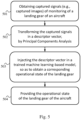
- Fig. 5 schematically illustrates a flowchart of a method for using the control device 101.
- the at least one capturing device such as the at least one video camera CAM1 201, CAM2 202, captures images of the monitored landing gear.
- the control device 101 obtains the captured signals from the at least one capturing device.
- the control device 101 obtains the captured images from the video camera CAM1201, CAM2 202 in real-time.
- the control device 101 transforms the captured signals (such as the captured images) into a descriptor vector by applying PCA.
- the step S502 is performed by the analyzer 251.
- control device 101 injects the descriptor vector in the model 252, so as to obtain in real-time a corresponding operational state of the monitored landing gear.
- control device 101 provides the operational state of the monitored landing gear to the avionics 100 of the aircraft 10, for example for further display in visual form to the pilot in the cockpit of the aircraft 10.
Landscapes
- Engineering & Computer Science (AREA)
- Aviation & Aerospace Engineering (AREA)
- Theoretical Computer Science (AREA)
- Software Systems (AREA)
- General Physics & Mathematics (AREA)
- Computer Vision & Pattern Recognition (AREA)
- Physics & Mathematics (AREA)
- Mechanical Engineering (AREA)
- Evolutionary Computation (AREA)
- General Engineering & Computer Science (AREA)
- Computing Systems (AREA)
- Mathematical Physics (AREA)
- Medical Informatics (AREA)
- Data Mining & Analysis (AREA)
- Artificial Intelligence (AREA)
- Manufacturing & Machinery (AREA)
- Transportation (AREA)
- Image Analysis (AREA)
- Testing Of Devices, Machine Parts, Or Other Structures Thereof (AREA)
Abstract
Description
- The present invention relates to the field of monitoring operations of landing gears of aircrafts.
- Landing gears of aircrafts are currently monitored using numerous sensors. Proximity sensors positioned at various locations in the landing gear vicinity make it possible to detect the actual position, or operating state, of the landing gear, and thus to check in particular that the release, deployment, retraction, locking in the up position and locking in the down position are properly working. In addition to their intrinsic cost, these various sensors require regular servicing and maintenance operations to ensure reliability of the landing gear.
- It is therefore desirable to provide a solution which makes it possible to dispense with all or some of these sensors for monitoring landing gears of aircrafts.
- To this end, it is disclosed herein a method for providing an operational state of a monitored landing gear of an aircraft, the method being performed by a system in electronic circuitry form, the method comprising: obtaining in real-time captured signals representative of an actual position of the monitored landing gear; transforming the captured signals in a descriptor vector using Principal Components Analysis; injecting the descriptor vector in a machine learning-based model trained and configured to transform descriptor vectors into equivalent operational states of landing gears; and providing the operational state of the monitored landing gear.
- Thus, thanks to the Principal Components Analysis on the captured signals (such as images) and to the trained machine learning-based model, the operational state of the monitored landing gear of the aircraft can easily be provided without having recourse to numerous sensors. Servicing and maintenance operations are therefore simplified.
- In a particular embodiment, the captured signals are captured images.
- In a particular embodiment, the images are captured by at least one video camera placed in the aircraft in the vicinity of the monitored landing gear, in such a way to capture images of the monitored landing gear, whatever is the operational state of the monitored landing gear during operations.
- In a particular embodiment, candidate operational states of landing gears are: up-locked, up-unlocked, in-transit, down-unlocked, and down-locked.
- In a particular embodiment, the operational state of the monitored landing gear is provided to avionics of the aircraft.
- It is further disclosed herein a computer program product comprising instructions causing execution, by a processor, of the method above in any one of its embodiments, when said instructions are executed by the processor. It is further disclosed herein a non-transitory storage medium storing instructions causing execution, by a processor, of the method above in any one of its embodiments, when said instructions are read from the non-transitory storage medium and executed by the processor.
- In a particular embodiment, the method beforehand comprises initializing the model by a computer system, as follows: obtaining a set of reference signals of candidate operational states of landing gears; generating, in un-supervised mode, a codebook of using Principal Components Analysis on the set of reference signals, the codebook gathering descriptor vectors obtained from the set of reference signals using Principal Components Analysis; building the machine learning-based model, in supervised mode, for labelling descriptor vectors with information representative of a corresponding operational state of landing gears.
- In a particular embodiment, the set of reference signals is a set of reference images consisting of a plurality of images of each candidate operational state, captured with different lighting conditions and/or with different background interference.
- It is further disclosed herein a system for providing an operational state of a monitored landing gear of an aircraft, the system comprising electronic circuitry configured for implementing: obtaining in real-time captured signals of the monitored landing gear; transforming the captured signals in a descriptor vector using Principal Components Analysis; injecting the descriptor vector in a machine learning-based model trained and configured to transform descriptor vectors into equivalent operational states of landing gears; and providing the operational state of the monitored landing gear.
- It is further disclosed herein an aircraft comprising the system above so as to monitor operations of at least one landing gear of the aircraft.
- The characteristics of the invention mentioned above, as well as others, will appear more clearly on reading the following description of at least one embodiment, said description being made with respect to the accompanying drawings, among which:
-
Fig. 1 schematically illustrates, in top view, an aircraft equipped with a system for monitoring operation of a landing gear, in a particular embodiment; -
Fig. 2 schematically illustrates an arrangement of a control device of the system for monitoring operation of a landing gear, in a particular embodiment; -
Fig. 3 schematically illustrates an example of a hardware platform configured for implementing the control device of the system for monitoring operation of a landing gear, in a particular embodiment; -
Fig. 4 schematically illustrates a flowchart of a method for initializing a model for transforming descriptor vectors into equivalent operational states of a landing gear; and -
Fig. 5 schematically illustrates a flowchart of a method for using the control device of the system for monitoring operation of a landing gear. -
Fig. 1 schematically illustrates, in top view, anaircraft 10. Theaircraft 10 comprisesavionics 100. Theavionics 100 include acontrol device 101 of asystem 200 for monitoring operation of at least one landing gear of theaircraft 10. Thecontrol device 101 may be located elsewhere in theaircraft 10, for example nearby each landing gear that is monitored by said system. Thecontrol device 101 is in communication with theavionics 100, for example using a dedicated wiring or using a shared communication bus, so as to report in real-time an operational state of each landing gear that is monitored by said system. - In a particular embodiment, candidate operational states of the landing gear are: up-locked, up-unlocked, in-transit, down-unlocked, and down-locked. Other candidate operational states may be added, more particularly to divide the in-transit state into refined substates.
- As shown in
Fig. 2 , thesystem 200 for monitoring operation of at least one landing gear of theaircraft 10 comprises at least one capturing device adapted and configured to capture in real-time signals representative of an actual position of the landing gear, whatever is the operational state of the landing gear in question during operations. The signals captured by the at least one capturing device are thus representative of the operational state of the landing gear in question. - In one embodiment, the capturing device is a video camera. The
system 200 for monitoring operation of at least one landing gear of theaircraft 10 thus comprises at least one video camera.Fig. 2 illustratively shows two video cameras CAM1 201 andCAM2 202. The at least one video camera CAM1 201, CAM2 202 are placed in the aircraft in the vicinity of the landing gear to be monitored, in such a way to capture images of the landing gear in question, whatever is the operational state of the landing gear in question during operations. The images captured by the at least one video camera CAM1 201,CAM2 202 are thus representative of the operational state of the landing gear in question. - In another embodiment, the capturing device is a LIDAR ("light detection and ranging" or "laser imaging detection and ranging") device. The light signals captured by the at least one LIDAR device are thus representative of the operational state of the landing gear in question.
- Signals captured by the at least one capturing device are transmitted, for example using dedicated wiring or using wireless communications, to the
control device 101 for further analysis thereof. For example, images captured by the at least one video camera CAM1 201,CAM2 202 are transmitted to thecontrol device 101 for further analysis thereof. - The
control device 101 comprises ananalyzer 251 configured for performing Principal Components Analysis (PCA) on signals captured by the at least one capturing device, such as the images captured by the at least one video camera CAM1 201,CAM2 202. - PCA is a statistical method for reducing dimensionality of a dataset by linearly transforming input data into a new coordinate system where the most meaningful part of data variation can be expressed with fewer dimensions. PCA is thus a process of computing principal components of a dataset and using said principal components to perform a change of basis. The first (most) principal component of a set of N original variables is a derived variable that is a linear combination of the N original variables and that exposes the most variance. The second principal component is a derived variable that is a linear combination of the N original variables and that exposes the most variance in what is left once the effect of the first principal component is removed. N iterations can thus be performed until all the variance is considered, even though fewer iterations are typically used when dimensionality reduction is targeted. The quantity of iterations to be performed is context dependent and can be defined by experiments, depending on targeted accuracy of data analysis. Using PCA on signals such as video images or LIDAR signals is particularly advantageous since such signals are highly correlated, which enables efficient dimensionality reduction.
- PCA is a dimensionality reduction technique that successively includes: feature covariance computation, eigen-decomposition, principal component transformation, and principal components selection. In other words, the principal components are determined by calculating the eigenvectors and eigenvalues of the input data covariance matrix. Once eigenvectors are found from the covariance matrix, the eigenvectors are ordered by eigenvalue, in descending order. It provides the principal components listed according to their significance. Principle components selection is performed in descending order of significance so as to form a descriptor vector.
- The
signals 261 output by the at least one capturing device, such as the images received from the at least one video camera CAM1 201,CAM2 202, are input to theanalyzer 251, which processes saidinput signals 261 according to PCA principles, so as to provide the descriptor vector 262 (also referred to as feature vector), which is therefore reduced in terms of dimensionality compared with theinput signals 261. - The
control device 101 comprises amodel 252 configured to transform descriptor vectors into equivalent operational states of the landing gear. Themodel 252 is a machine learning-based model trained to transform descriptor vectors into equivalent operational states of the landing gear. Thedescriptor vector 262 is thus input to themodel 252, which processes saiddescriptor vector 262, so as to provide an equivalentoperational state 263 of the monitored landing gear. Thecontrol device 101 is configured to provide said equivalentoperational state 263 to theavionics 100 so that a pilot of theaircraft 10 is informed in the cockpit about the operational state of the landing gear in question. - The
analyzer 251 and themodel 252 are initialized using a method which is disclosed hereafter with respect toFig. 4 . - The
analyzer 251 and themodel 252 jointly operate onboard the aircraft using a method which is disclosed in more detail hereafter with respect toFig. 5 . -
Fig. 3 schematically illustrates an example of ahardware platform 300, in form of electronic circuitry, which is configured to implement thecontrol device 101. - The
hardware platform 300 comprises, interconnected by a communication bus 310 : a processor or CPU ("Central Processing Unit") 301 ; a RAM ("Read-Only Memory") 302 ; a ROM ("Read Only Memory") 303 or EEPROM ("Electrically-Erasable Programmable ROM"), such as a Flash memory ; astorage device 304, such as a Hard Disk Drive or a reader device for reading a non-transitory storage medium, such as an SD ("Secure Digital") card reader; and an I/O ("Input/Output")manager 305. - The I/
O manager 305 enables thehardware platform 300 to interact with one or more items of equipment of theaircraft 10, such as theavionics 100 or other items of equipment of the system for monitoring operation of at least one landing gear of theaircraft 10, such as video cameras. -
CPU 301 is able to execute instructions loaded inRAM 302 fromROM 303, or from an external memory, or from a non-transitory storage medium (such as an SD card), or from a communications network. When thehardware platform 300 is powered up or booted,CPU 301 is able to read instructions fromRAM 302 and to execute these instructions. These instructions form a computer program causing implementation, byCPU 301, of all or part of the steps and operations disclosed herein with respect to thecontrol device 101. - All or part of the steps and operations disclosed herein with respect to the
control device 101 may be implemented in software form by executing a set of instructions by a programmable machine, such as a processor of DSP ("Digital Signal Processor") type or a microcontroller, or be implemented in hardware form by a chip or chipset, such as an FPGA ("Field Programmable Gate Array") or an ASIC ("Application Specific Integrated Circuit"). In general terms, thehardware platform 300 comprises electronic circuitry configured to implement all or part of the steps and operations disclosed herein with respect to thecontrol device 101. -
Fig. 4 schematically illustrates a flowchart of a method for initializing themodel 252. The method ofFig. 4 is performed by a computer system. The computer system is for example physically arranged according to thehardware platform 300 depicted inFig. 3 and detailed above with respect to thecontrol device 101. - In a
step 401, the computer system obtains a set of reference signals, such as reference images, of the candidate operational states of a reference landing gear. The reference landing gear corresponds to a type of landing gear equipping aircrafts for which monitoring of landing gear operations using the at least one capturing device, such as the aforementioned video cameras, is foreseen. The set of reference signals corresponds to signals which have been captured by at least one capturing device installed in a relative position with respect to the reference landing gear in substantially the same way as the at least one capturing device installed in the aircraft 10 (i.e., identical physical configuration for initialization and for on-the-field operations). When referring to the particular embodiment where in the at least one capturing device is at least one respective video camera, the set of reference images corresponds to images which have been captured by video cameras installed in a relative position with respect to the reference landing gear in substantially the same way as the at least one aforementioned video camera CAM1 201, CAM2 202 (i.e., identical physical configuration for initialization and for on-the-field operations). - The set of reference signals consists of at least one signal representative of each candidate operational state of the reference landing gear.
- When referring to the particular embodiment where in the at least one capturing device is at least one respective video camera, the set of reference signals is a set of reference images consisting of at least one image representative of each candidate operational state of the reference landing gear. The set of reference images preferably consists of a plurality of images of each operational state of the reference landing gear, captured with different lighting conditions and/or with different background interference, etc., in order to improve classification efficiency of the
model 252 to be initialized. - In a
step 402, the computer system generates a codebook using Principal Components Analysis on the set of reference signals (e.g., on the set of reference images). The codebook is generated in un-supervised mode, meaning automatically without human intervention. Each reference signal (e.g., reference image) is thus transformed in a descriptor vector, as already explained, and then included in the codebook. The generated codebook thus gathers the descriptor vectors of the reference signals (e.g., reference images), each descriptor vector being stored in the codebook and associated with the reference signals (e.g., the reference image) to which the descriptor vector in question corresponds, or associated with information derived from the reference signals (e.g. the reference image) to which the descriptor vector in question corresponds. - In a
step 403, the computer system builds themodel 252 for monitoring operation of a landing gear, using supervised machine learning. Themodel 252 is built from the generated codebook in supervised mode, meaning with human support for labelling descriptor vectors with information representative of a corresponding operational state of the landing gear. The reference signal (e.g., reference image) is used to determine to which operational state of the landing gear each descriptor vector corresponds. For example, an adequate label is found by visual inspection of the reference image in question. - For example, the
model 252 is built using logistic regression, Support Vector Machines (SVM), K-Nearest Neighbours (KNN), or any other supervised machine learning approach. - This completes the initialization of the
model 252. - In a
step 404, the computer system provides themodel 252. Themodel 252 is used in an aircraft for monitoring operation of a landing gear, as in thesystem 200 for monitoring operation of at least one landing gear of theaircraft 10. -
Fig. 5 schematically illustrates a flowchart of a method for using thecontrol device 101. - In a
step 501, the at least one capturing device, such as the at least one video camera CAM1 201,CAM2 202, captures images of the monitored landing gear. Thecontrol device 101 obtains the captured signals from the at least one capturing device. For example, thecontrol device 101 obtains the captured images from the video camera CAM1201,CAM2 202 in real-time. - In a
step 502, thecontrol device 101 transforms the captured signals (such as the captured images) into a descriptor vector by applying PCA. With respect toFig. 2 , the step S502 is performed by theanalyzer 251. - In a
step 503, thecontrol device 101 injects the descriptor vector in themodel 252, so as to obtain in real-time a corresponding operational state of the monitored landing gear. - In a
step 504, thecontrol device 101 provides the operational state of the monitored landing gear to theavionics 100 of theaircraft 10, for example for further display in visual form to the pilot in the cockpit of theaircraft 10.
Claims (11)
- A method for providing an operational state of a monitored landing gear of an aircraft (10), the method being performed by a system in electronic circuitry form, the method comprising:- obtaining (501) in real-time captured signals representative of an actual position of the monitored landing gear;- transforming (502) the captured signals in a descriptor vector using Principal Components Analysis;- injecting (503) the descriptor vector in a machine learning-based model (252) trained and configured to transform descriptor vectors into equivalent operational states of landing gears; and- providing (504) the operational state of the monitored landing gear.
- The method according to claim 1, wherein the captured signals are captured images.
- The method according to claim 2, wherein the images are captured by at least one video camera (201, 202) placed in the aircraft (10) in the vicinity of the monitored landing gear, in such a way to capture images of the monitored landing gear, whatever is the operational state of the monitored landing gear during operations.
- The method according to one of claims 1 to 3, wherein candidate operational states of landing gears are: up-locked, up-unlocked, in-transit, down-unlocked, and down-locked.
- The method according to any one of claims 1 to 4, wherein the operational state of the monitored landing gear is provided to avionics of the aircraft.
- The method according to any one of claims 1 to 5, wherein the method beforehand comprises initializing the model by a computer system, as follows:- obtaining (401) a set of reference signals representative of candidate operational states of landing gears;- generating (402), in un-supervised mode, a codebook of using Principal Components Analysis on the set of reference signals, the codebook gathering descriptor vectors obtained from the set of reference signals using Principal Components Analysis;- building (403) the machine learning-based model, in supervised mode, for labelling descriptor vectors with information representative of a corresponding operational state of landing gears.
- The method according to claim 6, wherein the set of reference signals is a set of reference images consisting of a plurality of images of each candidate operational state, captured with different lighting conditions and/or with different background interference.
- A computer program product comprising instructions causing execution, by a processor, of the method according to any one of claims 1 to 5, when said instructions are executed by the processor (301).
- A non-transitoray storage medium storing instructions causing execution, by a processor, of the method according to any one of claims 1 to 5, when said instructions are read from the non-transitoray storage medium and executed by the processor (301).
- A system for providing an operational state of a monitored landing gear of an aircraft (10), the system comprising electronic circuitry configured for implementing:- obtaining (501) in real-time captured signals representative of an actual position of the monitored landing gear;- transforming (502) the captured signals in a descriptor vector using Principal Components Analysis;- injecting (503) the descriptor vector in a machine learning-based model trained and configured to transform descriptor vectors into equivalent operational states of landing gears; and- providing (504) the operational state of the monitored landing gear.
- An aircraft (10) comprising the system according to claim 10 so as to monitor operations of at least one landing gear of the aircraft (10).
Priority Applications (3)
| Application Number | Priority Date | Filing Date | Title |
|---|---|---|---|
| EP23305125.9A EP4410683B1 (en) | 2023-01-31 | 2023-01-31 | Method and system for monitoring operations of landing gears of aircrafts |
| US18/425,142 US12692016B2 (en) | 2023-01-31 | 2024-01-29 | Method and system for monitoring operations of landing gears of aircraft |
| CN202410132015.7A CN118419276A (en) | 2023-01-31 | 2024-01-30 | Method and system for monitoring the operation of landing gear of an aircraft |
Applications Claiming Priority (1)
| Application Number | Priority Date | Filing Date | Title |
|---|---|---|---|
| EP23305125.9A EP4410683B1 (en) | 2023-01-31 | 2023-01-31 | Method and system for monitoring operations of landing gears of aircrafts |
Publications (2)
| Publication Number | Publication Date |
|---|---|
| EP4410683A1 true EP4410683A1 (en) | 2024-08-07 |
| EP4410683B1 EP4410683B1 (en) | 2025-11-12 |
Family
ID=85381084
Family Applications (1)
| Application Number | Title | Priority Date | Filing Date |
|---|---|---|---|
| EP23305125.9A Active EP4410683B1 (en) | 2023-01-31 | 2023-01-31 | Method and system for monitoring operations of landing gears of aircrafts |
Country Status (3)
| Country | Link |
|---|---|
| US (1) | US12692016B2 (en) |
| EP (1) | EP4410683B1 (en) |
| CN (1) | CN118419276A (en) |
Citations (4)
| Publication number | Priority date | Publication date | Assignee | Title |
|---|---|---|---|---|
| US20030011493A1 (en) * | 2001-06-11 | 2003-01-16 | Wiplinger Robert D. | Landing gear warning system |
| US8042765B1 (en) * | 2008-05-20 | 2011-10-25 | Nance C Kirk | Aircraft landing gear compression rate monitor |
| US20120095703A1 (en) * | 2010-10-15 | 2012-04-19 | Goodrich Corporation | Monitoring systems and methods for aircraft landing gear |
| US20170283085A1 (en) * | 2016-04-04 | 2017-10-05 | The Boeing Company | On-board structural load assessment of an aircraft during flight events |
Family Cites Families (8)
| Publication number | Priority date | Publication date | Assignee | Title |
|---|---|---|---|---|
| US7243048B2 (en) * | 2005-11-28 | 2007-07-10 | Honeywell International, Inc. | Fault detection system and method using multiway principal component analysis |
| US8379989B2 (en) * | 2008-04-01 | 2013-02-19 | Toyota Jidosha Kabushiki Kaisha | Image search apparatus and image processing apparatus |
| US10974852B2 (en) * | 2019-02-19 | 2021-04-13 | The Boeing Company | Aircraft landing gear monitoring systems and methods |
| IL285589B2 (en) * | 2019-02-25 | 2025-12-01 | Triumph Aerospace Operations Uk Ltd | Pin detection device in landing gear |
| US11919657B2 (en) * | 2020-05-06 | 2024-03-05 | The Boeing Company | Aircraft landing gear monitoring and alerting system and method |
| US12006062B2 (en) * | 2020-05-15 | 2024-06-11 | The Boeing Company | Method and system for reducing air-to-ground data traffic communicated from an aircraft |
| CN112429252B (en) * | 2020-11-24 | 2022-05-03 | 中国人民解放军空军预警学院 | Flight emergency prediction method based on PCA algorithm |
| US11955022B2 (en) * | 2021-08-11 | 2024-04-09 | Rosemount Aerospace Inc. | Aircraft door camera system for landing gear monitoring |
-
2023
- 2023-01-31 EP EP23305125.9A patent/EP4410683B1/en active Active
-
2024
- 2024-01-29 US US18/425,142 patent/US12692016B2/en active Active
- 2024-01-30 CN CN202410132015.7A patent/CN118419276A/en active Pending
Patent Citations (4)
| Publication number | Priority date | Publication date | Assignee | Title |
|---|---|---|---|---|
| US20030011493A1 (en) * | 2001-06-11 | 2003-01-16 | Wiplinger Robert D. | Landing gear warning system |
| US8042765B1 (en) * | 2008-05-20 | 2011-10-25 | Nance C Kirk | Aircraft landing gear compression rate monitor |
| US20120095703A1 (en) * | 2010-10-15 | 2012-04-19 | Goodrich Corporation | Monitoring systems and methods for aircraft landing gear |
| US20170283085A1 (en) * | 2016-04-04 | 2017-10-05 | The Boeing Company | On-board structural load assessment of an aircraft during flight events |
Also Published As
| Publication number | Publication date |
|---|---|
| EP4410683B1 (en) | 2025-11-12 |
| US20240253816A1 (en) | 2024-08-01 |
| US12692016B2 (en) | 2026-07-28 |
| CN118419276A (en) | 2024-08-02 |
Similar Documents
| Publication | Publication Date | Title |
|---|---|---|
| US11269321B2 (en) | Equipment diagnosis system and method based on deep learning | |
| KR102915961B1 (en) | System and method for finding and classifying patterns in an image with a vision system | |
| US11961218B2 (en) | Machine vision systems and methods for automatically generating one or more machine vision jobs based on region of interests (ROIs) of digital images | |
| US10222871B2 (en) | Resource-responsive motion capture | |
| US9651499B2 (en) | Configurable image trigger for a vision system and method for using the same | |
| US10699007B2 (en) | Hybrid univariate/multivariate prognostic-surveillance technique | |
| EP2825446B1 (en) | Airborne mine detection | |
| Khan et al. | Revolutionizing real-time object detection: YOLO and MobileNet SSD integration | |
| WO2016059576A1 (en) | System, apparatus and method for configuration of industrial vision control modules | |
| WO2021263193A1 (en) | Smart sensor | |
| CN112395936A (en) | System and method for detecting defects in a structure subject to repetitive stress | |
| US20230245433A1 (en) | Systems and Methods for Implementing a Hybrid Machine Vision Model to Optimize Performance of a Machine Vision Job | |
| EP4410683B1 (en) | Method and system for monitoring operations of landing gears of aircrafts | |
| Katare et al. | Real-time 3-d segmentation on an autonomous embedded system: using point cloud and camera | |
| Kumar et al. | Accelerating object detection with yolov4 for real-time applications | |
| CN113468048A (en) | System testing method, device, equipment and computer readable storage medium | |
| US20210109838A1 (en) | Information processing apparatus, method, and non-transitory recording medium | |
| WO2018037891A1 (en) | Image processing device, image processing system, image processing method, and program recording medium | |
| Behret et al. | Benchmarking a ros 2-based indirect slam on edge devices | |
| CN118570249A (en) | Visual tracking method, device and electronic device based on pulse neural network | |
| Thomas et al. | Design and development of industrial vision sensor (IVIS) for next generation industrial applications | |
| Nandikolla et al. | Vision based obstacle detection and navigation of an autonomous vehicle | |
| EP4625260A1 (en) | Computer-implemented method for testing a robustness of a pre-trained model | |
| US20260120453A1 (en) | System and method for detecting obstacles and alerting users using artificial intelligence in machine vision cameras | |
| Huang | Real-time Pedestrian Classification System Using Deep Learning on a Raspberry Pi Cluster |
Legal Events
| Date | Code | Title | Description |
|---|---|---|---|
| PUAI | Public reference made under article 153(3) epc to a published international application that has entered the european phase |
Free format text: ORIGINAL CODE: 0009012 |
|
| STAA | Information on the status of an ep patent application or granted ep patent |
Free format text: STATUS: THE APPLICATION HAS BEEN PUBLISHED |
|
| AK | Designated contracting states |
Kind code of ref document: A1 Designated state(s): AL AT BE BG CH CY CZ DE DK EE ES FI FR GB GR HR HU IE IS IT LI LT LU LV MC ME MK MT NL NO PL PT RO RS SE SI SK SM TR |
|
| STAA | Information on the status of an ep patent application or granted ep patent |
Free format text: STATUS: REQUEST FOR EXAMINATION WAS MADE |
|
| 17P | Request for examination filed |
Effective date: 20250204 |
|
| GRAP | Despatch of communication of intention to grant a patent |
Free format text: ORIGINAL CODE: EPIDOSNIGR1 |
|
| STAA | Information on the status of an ep patent application or granted ep patent |
Free format text: STATUS: GRANT OF PATENT IS INTENDED |
|
| INTG | Intention to grant announced |
Effective date: 20250610 |
|
| GRAS | Grant fee paid |
Free format text: ORIGINAL CODE: EPIDOSNIGR3 |
|
| GRAA | (expected) grant |
Free format text: ORIGINAL CODE: 0009210 |
|
| STAA | Information on the status of an ep patent application or granted ep patent |
Free format text: STATUS: THE PATENT HAS BEEN GRANTED |
|
| AK | Designated contracting states |
Kind code of ref document: B1 Designated state(s): AL AT BE BG CH CY CZ DE DK EE ES FI FR GB GR HR HU IE IS IT LI LT LU LV MC ME MK MT NL NO PL PT RO RS SE SI SK SM TR |
|
| REG | Reference to a national code |
Ref country code: CH Ref legal event code: F10 Free format text: ST27 STATUS EVENT CODE: U-0-0-F10-F00 (AS PROVIDED BY THE NATIONAL OFFICE) Effective date: 20251112 Ref country code: GB Ref legal event code: FG4D |
|
| REG | Reference to a national code |
Ref country code: DE Ref legal event code: R096 Ref document number: 602023008545 Country of ref document: DE |
|
| REG | Reference to a national code |
Ref country code: IE Ref legal event code: FG4D |
|
| REG | Reference to a national code |
Ref country code: NL Ref legal event code: MP Effective date: 20251112 |
|
| PG25 | Lapsed in a contracting state [announced via postgrant information from national office to epo] |
Ref country code: ES Free format text: LAPSE BECAUSE OF FAILURE TO SUBMIT A TRANSLATION OF THE DESCRIPTION OR TO PAY THE FEE WITHIN THE PRESCRIBED TIME-LIMIT Effective date: 20251112 |
|
| REG | Reference to a national code |
Ref country code: LT Ref legal event code: MG9D |
|
| PG25 | Lapsed in a contracting state [announced via postgrant information from national office to epo] |
Ref country code: NO Free format text: LAPSE BECAUSE OF FAILURE TO SUBMIT A TRANSLATION OF THE DESCRIPTION OR TO PAY THE FEE WITHIN THE PRESCRIBED TIME-LIMIT Effective date: 20260212 |
|
| PGFP | Annual fee paid to national office [announced via postgrant information from national office to epo] |
Ref country code: DE Payment date: 20260121 Year of fee payment: 4 |
|
| PG25 | Lapsed in a contracting state [announced via postgrant information from national office to epo] |
Ref country code: FI Free format text: LAPSE BECAUSE OF FAILURE TO SUBMIT A TRANSLATION OF THE DESCRIPTION OR TO PAY THE FEE WITHIN THE PRESCRIBED TIME-LIMIT Effective date: 20251112 Ref country code: HR Free format text: LAPSE BECAUSE OF FAILURE TO SUBMIT A TRANSLATION OF THE DESCRIPTION OR TO PAY THE FEE WITHIN THE PRESCRIBED TIME-LIMIT Effective date: 20251112 Ref country code: AT Free format text: LAPSE BECAUSE OF FAILURE TO SUBMIT A TRANSLATION OF THE DESCRIPTION OR TO PAY THE FEE WITHIN THE PRESCRIBED TIME-LIMIT Effective date: 20251112 |
|
| REG | Reference to a national code |
Ref country code: AT Ref legal event code: MK05 Ref document number: 1856589 Country of ref document: AT Kind code of ref document: T Effective date: 20251112 |
|
| PG25 | Lapsed in a contracting state [announced via postgrant information from national office to epo] |
Ref country code: NL Free format text: LAPSE BECAUSE OF FAILURE TO SUBMIT A TRANSLATION OF THE DESCRIPTION OR TO PAY THE FEE WITHIN THE PRESCRIBED TIME-LIMIT Effective date: 20251112 |
|
| PG25 | Lapsed in a contracting state [announced via postgrant information from national office to epo] |
Ref country code: RS Free format text: LAPSE BECAUSE OF FAILURE TO SUBMIT A TRANSLATION OF THE DESCRIPTION OR TO PAY THE FEE WITHIN THE PRESCRIBED TIME-LIMIT Effective date: 20260212 |
|
| PG25 | Lapsed in a contracting state [announced via postgrant information from national office to epo] |
Ref country code: IS Free format text: LAPSE BECAUSE OF FAILURE TO SUBMIT A TRANSLATION OF THE DESCRIPTION OR TO PAY THE FEE WITHIN THE PRESCRIBED TIME-LIMIT Effective date: 20260312 |
|
| PGFP | Annual fee paid to national office [announced via postgrant information from national office to epo] |
Ref country code: FR Payment date: 20260123 Year of fee payment: 4 |
|
| PG25 | Lapsed in a contracting state [announced via postgrant information from national office to epo] |
Ref country code: PT Free format text: LAPSE BECAUSE OF FAILURE TO SUBMIT A TRANSLATION OF THE DESCRIPTION OR TO PAY THE FEE WITHIN THE PRESCRIBED TIME-LIMIT Effective date: 20260312 |
|
| PG25 | Lapsed in a contracting state [announced via postgrant information from national office to epo] |
Ref country code: PL Free format text: LAPSE BECAUSE OF FAILURE TO SUBMIT A TRANSLATION OF THE DESCRIPTION OR TO PAY THE FEE WITHIN THE PRESCRIBED TIME-LIMIT Effective date: 20251112 |
|
| PG25 | Lapsed in a contracting state [announced via postgrant information from national office to epo] |
Ref country code: LV Free format text: LAPSE BECAUSE OF FAILURE TO SUBMIT A TRANSLATION OF THE DESCRIPTION OR TO PAY THE FEE WITHIN THE PRESCRIBED TIME-LIMIT Effective date: 20251112 |
|
| PG25 | Lapsed in a contracting state [announced via postgrant information from national office to epo] |
Ref country code: BG Free format text: LAPSE BECAUSE OF FAILURE TO SUBMIT A TRANSLATION OF THE DESCRIPTION OR TO PAY THE FEE WITHIN THE PRESCRIBED TIME-LIMIT Effective date: 20251112 |
|
| PG25 | Lapsed in a contracting state [announced via postgrant information from national office to epo] |
Ref country code: LT Free format text: LAPSE BECAUSE OF FAILURE TO SUBMIT A TRANSLATION OF THE DESCRIPTION OR TO PAY THE FEE WITHIN THE PRESCRIBED TIME-LIMIT Effective date: 20251112 |
|
| PG25 | Lapsed in a contracting state [announced via postgrant information from national office to epo] |
Ref country code: SM Free format text: LAPSE BECAUSE OF FAILURE TO SUBMIT A TRANSLATION OF THE DESCRIPTION OR TO PAY THE FEE WITHIN THE PRESCRIBED TIME-LIMIT Effective date: 20251112 |
|
| PG25 | Lapsed in a contracting state [announced via postgrant information from national office to epo] |
Ref country code: DK Free format text: LAPSE BECAUSE OF FAILURE TO SUBMIT A TRANSLATION OF THE DESCRIPTION OR TO PAY THE FEE WITHIN THE PRESCRIBED TIME-LIMIT Effective date: 20251112 |
|
| PG25 | Lapsed in a contracting state [announced via postgrant information from national office to epo] |
Ref country code: IT Free format text: LAPSE BECAUSE OF FAILURE TO SUBMIT A TRANSLATION OF THE DESCRIPTION OR TO PAY THE FEE WITHIN THE PRESCRIBED TIME-LIMIT Effective date: 20251112 |
|
| PG25 | Lapsed in a contracting state [announced via postgrant information from national office to epo] |
Ref country code: EE Free format text: LAPSE BECAUSE OF FAILURE TO SUBMIT A TRANSLATION OF THE DESCRIPTION OR TO PAY THE FEE WITHIN THE PRESCRIBED TIME-LIMIT Effective date: 20251112 |
|
| PG25 | Lapsed in a contracting state [announced via postgrant information from national office to epo] |
Ref country code: CZ Free format text: LAPSE BECAUSE OF FAILURE TO SUBMIT A TRANSLATION OF THE DESCRIPTION OR TO PAY THE FEE WITHIN THE PRESCRIBED TIME-LIMIT Effective date: 20251112 |
|
| PG25 | Lapsed in a contracting state [announced via postgrant information from national office to epo] |
Ref country code: SK Free format text: LAPSE BECAUSE OF FAILURE TO SUBMIT A TRANSLATION OF THE DESCRIPTION OR TO PAY THE FEE WITHIN THE PRESCRIBED TIME-LIMIT Effective date: 20251112 |
|
| PG25 | Lapsed in a contracting state [announced via postgrant information from national office to epo] |
Ref country code: SE Free format text: LAPSE BECAUSE OF FAILURE TO SUBMIT A TRANSLATION OF THE DESCRIPTION OR TO PAY THE FEE WITHIN THE PRESCRIBED TIME-LIMIT Effective date: 20251112 |