EP4410678A1 - Oxidizing agents for emergency power units - Google Patents
Oxidizing agents for emergency power units Download PDFInfo
- Publication number
- EP4410678A1 EP4410678A1 EP24152453.7A EP24152453A EP4410678A1 EP 4410678 A1 EP4410678 A1 EP 4410678A1 EP 24152453 A EP24152453 A EP 24152453A EP 4410678 A1 EP4410678 A1 EP 4410678A1
- Authority
- EP
- European Patent Office
- Prior art keywords
- fuel cell
- coolant
- oxidant
- cabin
- supply
- Prior art date
- Legal status (The legal status is an assumption and is not a legal conclusion. Google has not performed a legal analysis and makes no representation as to the accuracy of the status listed.)
- Granted
Links
Images


Classifications
-
- H—ELECTRICITY
- H01—ELECTRIC ELEMENTS
- H01M—PROCESSES OR MEANS, e.g. BATTERIES, FOR THE DIRECT CONVERSION OF CHEMICAL ENERGY INTO ELECTRICAL ENERGY
- H01M8/00—Fuel cells; Manufacture thereof
- H01M8/04—Auxiliary arrangements, e.g. for control of pressure or for circulation of fluids
- H01M8/04298—Processes for controlling fuel cells or fuel cell systems
- H01M8/04694—Processes for controlling fuel cells or fuel cell systems characterised by variables to be controlled
- H01M8/04701—Temperature
-
- B—PERFORMING OPERATIONS; TRANSPORTING
- B64—AIRCRAFT; AVIATION; COSMONAUTICS
- B64D—EQUIPMENT FOR FITTING IN OR TO AIRCRAFT; FLIGHT SUITS; PARACHUTES; ARRANGEMENT OR MOUNTING OF POWER PLANTS OR PROPULSION TRANSMISSIONS IN AIRCRAFT
- B64D41/00—Power installations for auxiliary purposes
-
- B—PERFORMING OPERATIONS; TRANSPORTING
- B60—VEHICLES IN GENERAL
- B60L—PROPULSION OF ELECTRICALLY-PROPELLED VEHICLES; SUPPLYING ELECTRIC POWER FOR AUXILIARY EQUIPMENT OF ELECTRICALLY-PROPELLED VEHICLES; ELECTRODYNAMIC BRAKE SYSTEMS FOR VEHICLES IN GENERAL; MAGNETIC SUSPENSION OR LEVITATION FOR VEHICLES; MONITORING OPERATING VARIABLES OF ELECTRICALLY-PROPELLED VEHICLES; ELECTRIC SAFETY DEVICES FOR ELECTRICALLY-PROPELLED VEHICLES
- B60L50/00—Electric propulsion with power supplied within the vehicle
- B60L50/50—Electric propulsion with power supplied within the vehicle using propulsion power supplied by batteries or fuel cells
- B60L50/70—Electric propulsion with power supplied within the vehicle using propulsion power supplied by batteries or fuel cells using power supplied by fuel cells
-
- B—PERFORMING OPERATIONS; TRANSPORTING
- B60—VEHICLES IN GENERAL
- B60L—PROPULSION OF ELECTRICALLY-PROPELLED VEHICLES; SUPPLYING ELECTRIC POWER FOR AUXILIARY EQUIPMENT OF ELECTRICALLY-PROPELLED VEHICLES; ELECTRODYNAMIC BRAKE SYSTEMS FOR VEHICLES IN GENERAL; MAGNETIC SUSPENSION OR LEVITATION FOR VEHICLES; MONITORING OPERATING VARIABLES OF ELECTRICALLY-PROPELLED VEHICLES; ELECTRIC SAFETY DEVICES FOR ELECTRICALLY-PROPELLED VEHICLES
- B60L58/00—Methods or circuit arrangements for monitoring or controlling batteries or fuel cells, specially adapted for electric vehicles
- B60L58/30—Methods or circuit arrangements for monitoring or controlling batteries or fuel cells, specially adapted for electric vehicles for monitoring or controlling fuel cells
- B60L58/32—Methods or circuit arrangements for monitoring or controlling batteries or fuel cells, specially adapted for electric vehicles for monitoring or controlling fuel cells for controlling the temperature of fuel cells, e.g. by controlling the electric load
- B60L58/33—Methods or circuit arrangements for monitoring or controlling batteries or fuel cells, specially adapted for electric vehicles for monitoring or controlling fuel cells for controlling the temperature of fuel cells, e.g. by controlling the electric load by cooling
-
- B—PERFORMING OPERATIONS; TRANSPORTING
- B64—AIRCRAFT; AVIATION; COSMONAUTICS
- B64D—EQUIPMENT FOR FITTING IN OR TO AIRCRAFT; FLIGHT SUITS; PARACHUTES; ARRANGEMENT OR MOUNTING OF POWER PLANTS OR PROPULSION TRANSMISSIONS IN AIRCRAFT
- B64D13/00—Arrangements or adaptations of air-treatment apparatus for aircraft crew or passengers, or freight space
- B64D13/06—Arrangements or adaptations of air-treatment apparatus for aircraft crew or passengers, or freight space the air being conditioned
-
- B—PERFORMING OPERATIONS; TRANSPORTING
- B64—AIRCRAFT; AVIATION; COSMONAUTICS
- B64D—EQUIPMENT FOR FITTING IN OR TO AIRCRAFT; FLIGHT SUITS; PARACHUTES; ARRANGEMENT OR MOUNTING OF POWER PLANTS OR PROPULSION TRANSMISSIONS IN AIRCRAFT
- B64D33/00—Arrangement in aircraft of power plant parts or auxiliaries not otherwise provided for
- B64D33/08—Arrangement in aircraft of power plant parts or auxiliaries not otherwise provided for of power plant cooling systems
-
- H—ELECTRICITY
- H01—ELECTRIC ELEMENTS
- H01M—PROCESSES OR MEANS, e.g. BATTERIES, FOR THE DIRECT CONVERSION OF CHEMICAL ENERGY INTO ELECTRICAL ENERGY
- H01M8/00—Fuel cells; Manufacture thereof
- H01M8/04—Auxiliary arrangements, e.g. for control of pressure or for circulation of fluids
- H01M8/04007—Auxiliary arrangements, e.g. for control of pressure or for circulation of fluids related to heat exchange
- H01M8/04014—Heat exchange using gaseous fluids; Heat exchange by combustion of reactants
-
- H—ELECTRICITY
- H01—ELECTRIC ELEMENTS
- H01M—PROCESSES OR MEANS, e.g. BATTERIES, FOR THE DIRECT CONVERSION OF CHEMICAL ENERGY INTO ELECTRICAL ENERGY
- H01M8/00—Fuel cells; Manufacture thereof
- H01M8/04—Auxiliary arrangements, e.g. for control of pressure or for circulation of fluids
- H01M8/04082—Arrangements for control of reactant parameters, e.g. pressure or concentration
- H01M8/04089—Arrangements for control of reactant parameters, e.g. pressure or concentration of gaseous reactants
- H01M8/04111—Arrangements for control of reactant parameters, e.g. pressure or concentration of gaseous reactants using a compressor turbine assembly
-
- B—PERFORMING OPERATIONS; TRANSPORTING
- B60—VEHICLES IN GENERAL
- B60L—PROPULSION OF ELECTRICALLY-PROPELLED VEHICLES; SUPPLYING ELECTRIC POWER FOR AUXILIARY EQUIPMENT OF ELECTRICALLY-PROPELLED VEHICLES; ELECTRODYNAMIC BRAKE SYSTEMS FOR VEHICLES IN GENERAL; MAGNETIC SUSPENSION OR LEVITATION FOR VEHICLES; MONITORING OPERATING VARIABLES OF ELECTRICALLY-PROPELLED VEHICLES; ELECTRIC SAFETY DEVICES FOR ELECTRICALLY-PROPELLED VEHICLES
- B60L2200/00—Type of vehicles
- B60L2200/10—Air crafts
-
- B—PERFORMING OPERATIONS; TRANSPORTING
- B64—AIRCRAFT; AVIATION; COSMONAUTICS
- B64D—EQUIPMENT FOR FITTING IN OR TO AIRCRAFT; FLIGHT SUITS; PARACHUTES; ARRANGEMENT OR MOUNTING OF POWER PLANTS OR PROPULSION TRANSMISSIONS IN AIRCRAFT
- B64D13/00—Arrangements or adaptations of air-treatment apparatus for aircraft crew or passengers, or freight space
- B64D13/06—Arrangements or adaptations of air-treatment apparatus for aircraft crew or passengers, or freight space the air being conditioned
- B64D2013/0603—Environmental Control Systems
- B64D2013/0611—Environmental Control Systems combined with auxiliary power units (APU's)
-
- B—PERFORMING OPERATIONS; TRANSPORTING
- B64—AIRCRAFT; AVIATION; COSMONAUTICS
- B64D—EQUIPMENT FOR FITTING IN OR TO AIRCRAFT; FLIGHT SUITS; PARACHUTES; ARRANGEMENT OR MOUNTING OF POWER PLANTS OR PROPULSION TRANSMISSIONS IN AIRCRAFT
- B64D13/00—Arrangements or adaptations of air-treatment apparatus for aircraft crew or passengers, or freight space
- B64D13/06—Arrangements or adaptations of air-treatment apparatus for aircraft crew or passengers, or freight space the air being conditioned
- B64D2013/0603—Environmental Control Systems
- B64D2013/0618—Environmental Control Systems with arrangements for reducing or managing bleed air, using another air source, e.g. ram air
-
- B—PERFORMING OPERATIONS; TRANSPORTING
- B64—AIRCRAFT; AVIATION; COSMONAUTICS
- B64D—EQUIPMENT FOR FITTING IN OR TO AIRCRAFT; FLIGHT SUITS; PARACHUTES; ARRANGEMENT OR MOUNTING OF POWER PLANTS OR PROPULSION TRANSMISSIONS IN AIRCRAFT
- B64D13/00—Arrangements or adaptations of air-treatment apparatus for aircraft crew or passengers, or freight space
- B64D13/06—Arrangements or adaptations of air-treatment apparatus for aircraft crew or passengers, or freight space the air being conditioned
- B64D2013/0603—Environmental Control Systems
- B64D2013/0648—Environmental Control Systems with energy recovery means, e.g. using turbines
-
- B—PERFORMING OPERATIONS; TRANSPORTING
- B64—AIRCRAFT; AVIATION; COSMONAUTICS
- B64D—EQUIPMENT FOR FITTING IN OR TO AIRCRAFT; FLIGHT SUITS; PARACHUTES; ARRANGEMENT OR MOUNTING OF POWER PLANTS OR PROPULSION TRANSMISSIONS IN AIRCRAFT
- B64D41/00—Power installations for auxiliary purposes
- B64D2041/005—Fuel cells
-
- H—ELECTRICITY
- H01—ELECTRIC ELEMENTS
- H01M—PROCESSES OR MEANS, e.g. BATTERIES, FOR THE DIRECT CONVERSION OF CHEMICAL ENERGY INTO ELECTRICAL ENERGY
- H01M2250/00—Fuel cells for particular applications; Specific features of fuel cell system
- H01M2250/20—Fuel cells in motive systems, e.g. vehicle, ship, plane
-
- Y—GENERAL TAGGING OF NEW TECHNOLOGICAL DEVELOPMENTS; GENERAL TAGGING OF CROSS-SECTIONAL TECHNOLOGIES SPANNING OVER SEVERAL SECTIONS OF THE IPC; TECHNICAL SUBJECTS COVERED BY FORMER USPC CROSS-REFERENCE ART COLLECTIONS [XRACs] AND DIGESTS
- Y02—TECHNOLOGIES OR APPLICATIONS FOR MITIGATION OR ADAPTATION AGAINST CLIMATE CHANGE
- Y02E—REDUCTION OF GREENHOUSE GAS [GHG] EMISSIONS, RELATED TO ENERGY GENERATION, TRANSMISSION OR DISTRIBUTION
- Y02E60/00—Enabling technologies; Technologies with a potential or indirect contribution to GHG emissions mitigation
- Y02E60/30—Hydrogen technology
- Y02E60/50—Fuel cells
-
- Y—GENERAL TAGGING OF NEW TECHNOLOGICAL DEVELOPMENTS; GENERAL TAGGING OF CROSS-SECTIONAL TECHNOLOGIES SPANNING OVER SEVERAL SECTIONS OF THE IPC; TECHNICAL SUBJECTS COVERED BY FORMER USPC CROSS-REFERENCE ART COLLECTIONS [XRACs] AND DIGESTS
- Y02—TECHNOLOGIES OR APPLICATIONS FOR MITIGATION OR ADAPTATION AGAINST CLIMATE CHANGE
- Y02T—CLIMATE CHANGE MITIGATION TECHNOLOGIES RELATED TO TRANSPORTATION
- Y02T90/00—Enabling technologies or technologies with a potential or indirect contribution to GHG emissions mitigation
- Y02T90/40—Application of hydrogen technology to transportation, e.g. using fuel cells
Definitions
- the present disclosure relates to oxidizing agents, and more particularly to oxidizing agents for emergency power units (e.g., for aircraft).
- the first heat transfer device 126 includes a cold plate and the second heat transfer device 138 includes a multi-fluid heat exchanger.
- the cold plate 126 can have an internal channel 146 extending between an inlet 148 and an outlet 150 for passing the first coolant 130 through the cold plate 126.
- the multi-fluid heat exchanger 138 can have a first channel 152 therein, the first channel 152 extending between a first inlet 154 and a first outlet 156 for passing the first coolant 130 through the multi-fluid heat exchanger 138.
- the oxidant supply system 108 is fluidly connected to an environmental control system 168 of the aircraft.
- the compressor 114 can be a cabin air compressor 114 operatively connected to supply air to an aircraft cabin 170 and the oxidant 106 can be cabin air compressor exhaust.
- the compressor 114 may not be connected (e.g., mechanically connected) to the turbine 116 of the fuel cell system 102.
- the oxidant supply line 110 can include a branch point 172 upstream of the aircraft cabin 170 and upstream of the fuel cell 112. At the branch point, a portion of the cabin air compressor exhaust 106 can be diverted to the fuel cell 112 for oxidizing and a portion of the cabin air compressor exhaust 106 can be diverted to the aircraft cabin 170 (e.g., for passenger consumption).
- the emergency power unit system 200 can be similar to that of the emergency power unit system 100, for example emergency power unit system 200 can have similar components and features with respect to emergency power unit system 100.
- emergency power unit system 200 can have similar components and features with respect to emergency power unit system 100.
- the description of common elements that have been described above for emergency power unit system 100 are not repeated with respect to emergency power unit system 200 as shown in Fig. 2 .
- a heat exchanger 274 (e.g., separate from the thermal management system 124) can be included in the oxidant supply line 210 upstream of the branch point 272 configured to cool the cabin air compressor exhaust 206 before the cabin air is diverted to the fuel cell 112 and the cabin 170.
- the emergency power unit system 300 can be similar to that of the emergency power unit system 200, for example emergency power unit 200 can have similar components and features with respect to emergency power unit 100.
- emergency power unit 200 can have similar components and features with respect to emergency power unit 100.
- the description of common elements that have been described above for emergency power unit 100 are not repeated with respect to emergency power unit 200 as shown in Fig. 2
- the oxidant supply line 310 can include a branch point 372, and at the branch point 372, a portion of the cabin air 306 can be diverted to the fuel cell 112 for oxidizing and a portion of the cabin air 306 can be exhausted to ambient (e.g., outside of the cabin).
- the oxidant supply system 308 supplies the oxidant (cabin air) directly from the cabin 372, thus the branch point 372 can be the aircraft cabin 370 itself In this case, the air from the cabin 372 that has been used for passenger consumption is already pressurized before reaching the fuel cell 112, so a smaller quantity of air is needed as the oxidant to generate power by the fuel cell 112.
- the heat exchanger 374 can be disposed in the oxidant supply line 310 upstream of the aircraft cabin 372 configured to cool the cabin air compressor exhaust before the cabin air compressor exhaust 306 is supplied to the aircraft cabin 372. This can be particularly useful when the aircraft is closer to the ground where the supply air is hotter than at higher altitudes, or in situations where the cabin air compressor 114 is not functional (e.g., in an emergency or power outage).
- Embodiments allow for the fuel cell system to piggy-back on the cabin air compressor to supply at least some, if not all, of the oxidant for the fuel cell system.
- the compressor design for the fuel cell system can be simplified because the flow rate of the cabin air compressor would be higher than a dedicated compressor for the fuel cell, as in traditional systems, for example.
- Embodiments can reduce the number of ram air scoops for supplying air to the oxidant supply system.
- the emergency power unit system 100, 200, 300 can utilize only a single ram air scoop for supplying air to the cabin air compressor (the compressor supplying the oxidant to the fuel cell system).
- using the cabin air compressor, and in certain embodiments including a heat exchanger upstream of the fuel cell system can provide ideal air temperatures to the fuel cell.
- embodiments can provide air to the inlet of the fuel cell at temperature less than 98° C.
- any numerical values disclosed herein can be exact values or can be values within a range. Further, any terms of approximation (e.g., “about”, “approximately”, “around”) used in this disclosure can mean the stated value within a range. For example, in certain embodiments, the range can be within (plus or minus) 20%, or within 10%, or within 5%, or within 2%, or within any other suitable percentage or number as appreciated by those having ordinary skill in the art (e.g., for known tolerance limits or error ranges).
- a reference to "A and/or B", when used in conjunction with open-ended language such as “comprising” can refer, in one embodiment, to A only (optionally including elements other than B); in another embodiment, to B only (optionally including elements other than A); in yet another embodiment, to both A and B (optionally including other elements); etc.
Landscapes
- Engineering & Computer Science (AREA)
- Life Sciences & Earth Sciences (AREA)
- Sustainable Development (AREA)
- Sustainable Energy (AREA)
- Chemical & Material Sciences (AREA)
- Aviation & Aerospace Engineering (AREA)
- General Chemical & Material Sciences (AREA)
- Electrochemistry (AREA)
- Chemical Kinetics & Catalysis (AREA)
- Mechanical Engineering (AREA)
- Manufacturing & Machinery (AREA)
- Combustion & Propulsion (AREA)
- Power Engineering (AREA)
- Transportation (AREA)
- Health & Medical Sciences (AREA)
- General Health & Medical Sciences (AREA)
- Pulmonology (AREA)
- Fuel Cell (AREA)
Abstract
Description
- The present disclosure relates to oxidizing agents, and more particularly to oxidizing agents for emergency power units (e.g., for aircraft).
- Typical emergency power units use a ram air turbine to generate power in an emergency as well as use ram air as a coolant in one or more applications. A fuel cell can be used as an emergency power unit, but the operating temperature needs to be management to function properly. Traditional thermal management systems for fuel cells can be physically large, can be heavy, and/or can induce a drag on the aircraft. Additionally, a fuel cell needs an oxidizing agent to function. However, supplying compressible fluids to the fuel cell in lower power applications can be difficult.
- There is always a need in the art for improvements to emergency power units in the aerospace industry, and in particular, generating and/or supplying oxidizing agents for said emergency power units. This disclosure provides a solution for this need.
- In accordance with at least one aspect of this disclosure, an emergency power unit system for an aircraft includes a fuel cell system configured to generate power using a fuel and an oxidant, and an oxidant supply system fluidly connected to the fuel cell system to supply the oxidant to the fuel cell system via an oxidant supply line. The oxidant supply system is fluidly connected to an environmental control system of an aircraft.
- In embodiments, the fuel cell system can include, a fuel cell fluidly connected to the oxidant supply line to receive the oxidant; a compressor configured to receive the oxidant and compress the oxidant upstream of the fuel cell, and a turbine downstream from the fuel cell to receive exhaust flow and operatively connected to the compressor to turn the compressor.
- In embodiments, the compressor can be a cabin air compressor operatively connected to supply air to an aircraft cabin and the oxidant can be cabin air compressor exhaust.
- In certain embodiments, the oxidant supply line can include a branch point upstream of the aircraft cabin, and at the branch point, a portion of the cabin air compressor exhaust can be diverted to the fuel cell for oxidizing and a portion of the cabin air compressor exhaust can be diverted to the aircraft cabin. In certain embodiments, a heat exchanger can be included in the oxidant supply line upstream of the branch point configured to cool the cabin air compressor exhaust before the cabin air is diverted to the fuel cell and the cabin.
- In certain embodiments, the oxidant supply line can include a branch point, and at the branch point, a portion of the cabin air can be diverted to the fuel cell for oxidizing and a portion of the cabin air can be exhausted to ambient. In certain embodiments, the branch point can be the aircraft cabin. In certain such embodiments, the turbine downstream from the fuel cell configured to receive exhaust flow from the fuel cell can be operatively connected to turn a generator to generate electrical power, and may not be connected to another compressor. In certain such embodiments, a heat exchanger can be disposed in the oxidant supply line upstream of the aircraft cabin configured to cool the cabin air compressor exhaust before the cabin air compressor exhaust is supplied to the aircraft cabin.
- In embodiments, a fuel supply system can be fluidly connected to the fuel cell system to supply the fuel to the fuel cell system via a fuel supply line, the fuel cell fluidly connected to the fuel supply line to receive the fuel. A thermal management system can be in thermal communication with the fuel cell system to divert heat from the fuel cell system to the thermal management system.
- In embodiments, the thermal management system can include a heat transfer device disposed in a coolant flow path configured to receive a coolant from a coolant supply to exchange heat between the fuel cell system and the coolant in the coolant flow path.
- In embodiments, the heat transfer device can be a first heat transfer device, and the thermal management system can include a second heat transfer device disposed in the coolant flow path to receive the first coolant from the first coolant flow path. The second heat transfer device can be disposed in a second coolant flow path fluidly isolated from the first coolant flow path, configured to receive a second coolant from a second coolant supply through the second heat transfer device to exchange heat between the first coolant and the second coolant.
- In certain embodiments, the first heat transfer device includes a cold plate and wherein the second heat transfer device includes a multi-fluid heat exchanger. The cold plate can have a channel therein, the channel extending between an inlet and an outlet for passing the first coolant through the cold plate. The multi-fluid heat exchanger can have a first channel therein, the first channel extending between a first inlet and a first outlet for passing the first coolant through the multi-fluid heat exchanger. The multi-fluid heat exchanger can have a second channel therein, the second channel extending between a second inlet and a second outlet for passing the second coolant through the multi-fluid heat exchanger. The first channel and the second channel are in thermal communication and in fluid isolation with respect to one another within the multi-fluid heat exchanger.
- In embodiments, the first coolant supply can include a refrigerant tank and the first coolant can include refrigerant. In certain embodiments, the second coolant supply can include a ram air turbine and the second coolant can include ram air. In certain embodiments, the first coolant flow path can be coolant loop, and an outlet of the second coolant flow path can be configured to exhaust the ram air to ambient.
- These and other features of the embodiments of the subject disclosure will become more readily apparent to those skilled in the art from the following detailed description taken in conjunction with the drawings.
- So that those skilled in the art to which the subject disclosure appertains will readily understand how to make and use the devices and methods of the subject disclosure without undue experimentation, embodiments thereof will be described in detail herein below with reference to certain figures, wherein:
-
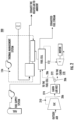
Fig. 1 is a schematic diagram of an emergency power unit system in accordance with this disclosure, showing an embodiment of an oxidant supply system; -
Fig. 2 is a schematic diagram of an emergency power unit system in accordance with this disclosure, showing another embodiment of an oxidant supply system; and -
Fig. 3 is a schematic diagram of an emergency power unit system in accordance with this disclosure, showing another embodiment of an oxidant supply system. - Reference will now be made to the drawings wherein like reference numerals identify similar structural features or aspects of the subject disclosure. For purposes of explanation and illustration, and not limitation, an illustrative view of an embodiment of a system in accordance with the disclosure is shown in
Fig. 1 and is designated generally byreference character 100. Other embodiments and/or aspects of this disclosure are shown inFigs. 2-3 . - In accordance with at least one aspect of this disclosure, an emergency
power unit system 100 for an aircraft includes afuel cell system 102 configured to generate power using afuel 104 and anoxidant 106, and anoxidant supply system 108 fluidly connected to thefuel cell system 102 to supply theoxidant 106 to thefuel cell system 102 via anoxidant supply line 110. - In embodiments, the
fuel cell system 102 can include, afuel cell 112 fluidly connected to theoxidant supply line 110 to receive theoxidant 106, acompressor 114 configured to receive theoxidant 106 and compress theoxidant 106 upstream of thefuel cell 112, and aturbine 116 downstream from thefuel cell 112 to receiveexhaust flow 118 and operatively connected to thecompressor 114 to turn thecompressor 114. For example, in certain embodiments, the turbine can be connected to thecompressor 114 via a shaft. In certain embodiments, thecompressor 114 may be mechanically disconnected from theturbine 116. In such embodiments, theturbine 116 can be operatively connected to turn a generator to generate electrical power, and may not be connected to another compressor. - A
fuel supply system 120 can be fluidly connected to thefuel cell system 102 to supply thefuel 104 to thefuel cell system 102 via afuel supply line 122, thefuel cell 112 fluidly connected to thefuel supply line 122 to receive thefuel 104. Athermal management system 124 can be in thermal communication with thefuel cell system 102 to divert heat from thefuel cell system 102 to thethermal management system 124. - In embodiments, the
thermal management system 124 can include aheat transfer device 126 disposed in acoolant flow path 128 configured to receive acoolant 130 from acoolant supply 132 to exchange heat between thefuel cell system 102 and thecoolant 130 in thecoolant flow path 128. Thecoolant supply 132 can include acoolant tank 134 and pump 136. - In embodiments, the
heat transfer device 126 can be a first heat transfer device, and thethermal management system 124 can include a secondheat transfer device 138 disposed in thecoolant flow path 128 to receive thefirst coolant 130 from the firstcoolant flow path 128. The secondheat transfer device 138 can also be disposed in asecond coolant flow 140 path fluidly isolated from the firstcoolant flow path 128 within the secondheat transfer device 138. The secondheat transfer device 138 can be configured to receive asecond coolant 142 from asecond coolant supply 144 through the secondheat transfer device 138 to exchange heat between thefirst coolant 130 and thesecond coolant 142. - In certain embodiments, the first
heat transfer device 126 includes a cold plate and the secondheat transfer device 138 includes a multi-fluid heat exchanger. Thecold plate 126 can have aninternal channel 146 extending between aninlet 148 and anoutlet 150 for passing thefirst coolant 130 through thecold plate 126. Themulti-fluid heat exchanger 138 can have afirst channel 152 therein, thefirst channel 152 extending between afirst inlet 154 and afirst outlet 156 for passing thefirst coolant 130 through themulti-fluid heat exchanger 138. Themulti-fluid heat exchanger 138 can have asecond channel 158 therein, thesecond channel 158 extending between asecond inlet 160 and asecond outlet 162 for passing thesecond coolant 142 through themulti-fluid heat exchanger 138. Thefirst channel 152 and thesecond channel 158 are in thermal communication but in fluid isolation with respect to one another within themulti-fluid heat exchanger 138. - In embodiments, the
first coolant supply 132 can include arefrigerant tank 134 and thefirst coolant 130 can include refrigerant (e.g., glycol or the like). In certain embodiments, thesecond coolant supply 144 can include aram air duct 164 and thesecond coolant 142 can include ram air. Any other suitable coolant supply is contemplated herein, for example, aircraft greywater, aircraft fuel, or aircraft cabin air. In certain embodiments, the firstcoolant flow path 128 can be coolant loop where the pump 136 can be a recirculation pump. Anoutlet 166 of the secondcoolant flow path 140 can be configured to exhaust theram air 142 to ambient. - In certain embodiments, such as shown in
Fig. 1 , theoxidant supply system 108 is fluidly connected to anenvironmental control system 168 of the aircraft. In embodiments, thecompressor 114 can be acabin air compressor 114 operatively connected to supply air to anaircraft cabin 170 and theoxidant 106 can be cabin air compressor exhaust. Here thecompressor 114 may not be connected (e.g., mechanically connected) to theturbine 116 of thefuel cell system 102. In certain embodiments, theoxidant supply line 110 can include abranch point 172 upstream of theaircraft cabin 170 and upstream of thefuel cell 112. At the branch point, a portion of the cabinair compressor exhaust 106 can be diverted to thefuel cell 112 for oxidizing and a portion of the cabinair compressor exhaust 106 can be diverted to the aircraft cabin 170 (e.g., for passenger consumption). - With reference now to
Fig. 2 , another embodiment of an emergencypower unit system 200 is shown. The emergencypower unit system 200 can be similar to that of the emergencypower unit system 100, for example emergencypower unit system 200 can have similar components and features with respect to emergencypower unit system 100. For brevity, the description of common elements that have been described above for emergencypower unit system 100 are not repeated with respect to emergencypower unit system 200 as shown inFig. 2 . - In certain embodiments, a heat exchanger 274 (e.g., separate from the thermal management system 124) can be included in the
oxidant supply line 210 upstream of thebranch point 272 configured to cool the cabinair compressor exhaust 206 before the cabin air is diverted to thefuel cell 112 and thecabin 170. - With reference now to
Fig. 3 , another embodiment of an emergencypower unit system 300 is shown. The emergencypower unit system 300 can be similar to that of the emergencypower unit system 200, for exampleemergency power unit 200 can have similar components and features with respect toemergency power unit 100. For brevity, the description of common elements that have been described above foremergency power unit 100 are not repeated with respect toemergency power unit 200 as shown inFig. 2 - In certain embodiments, the
oxidant supply line 310 can include abranch point 372, and at thebranch point 372, a portion of thecabin air 306 can be diverted to thefuel cell 112 for oxidizing and a portion of thecabin air 306 can be exhausted to ambient (e.g., outside of the cabin). Here, theoxidant supply system 308 supplies the oxidant (cabin air) directly from thecabin 372, thus thebranch point 372 can be theaircraft cabin 370 itself In this case, the air from thecabin 372 that has been used for passenger consumption is already pressurized before reaching thefuel cell 112, so a smaller quantity of air is needed as the oxidant to generate power by thefuel cell 112. Theheat exchanger 374 can be disposed in theoxidant supply line 310 upstream of theaircraft cabin 372 configured to cool the cabin air compressor exhaust before the cabinair compressor exhaust 306 is supplied to theaircraft cabin 372. This can be particularly useful when the aircraft is closer to the ground where the supply air is hotter than at higher altitudes, or in situations where thecabin air compressor 114 is not functional (e.g., in an emergency or power outage). - Embodiments allow for the fuel cell system to piggy-back on the cabin air compressor to supply at least some, if not all, of the oxidant for the fuel cell system. The compressor design for the fuel cell system can be simplified because the flow rate of the cabin air compressor would be higher than a dedicated compressor for the fuel cell, as in traditional systems, for example. Embodiments can reduce the number of ram air scoops for supplying air to the oxidant supply system. For example, the emergency
power unit system - Those having ordinary skill in the art understand that any numerical values disclosed herein can be exact values or can be values within a range. Further, any terms of approximation (e.g., "about", "approximately", "around") used in this disclosure can mean the stated value within a range. For example, in certain embodiments, the range can be within (plus or minus) 20%, or within 10%, or within 5%, or within 2%, or within any other suitable percentage or number as appreciated by those having ordinary skill in the art (e.g., for known tolerance limits or error ranges).
- The articles "a", "an", and "the" as used herein and in the appended claims are used herein to refer to one or to more than one (i.e., to at least one) of the grammatical object of the article unless the context clearly indicates otherwise. By way of example, "an element" means one element or more than one element.
- The phrase "and/or," as used herein in the specification and in the claims, should be understood to mean "either or both" of the elements so conjoined, i.e., elements that are conjunctively present in some cases and disjunctively present in other cases. Multiple elements listed with "and/or" should be construed in the same fashion, i.e., "one or more" of the elements so conjoined. Other elements may optionally be present other than the elements specifically identified by the "and/or" clause, whether related or unrelated to those elements specifically identified. Thus, as a non-limiting example, a reference to "A and/or B", when used in conjunction with open-ended language such as "comprising" can refer, in one embodiment, to A only (optionally including elements other than B); in another embodiment, to B only (optionally including elements other than A); in yet another embodiment, to both A and B (optionally including other elements); etc.
- As used herein in the specification and in the claims, "or" should be understood to have the same meaning as "and/or" as defined above. For example, when separating items in a list, "or" or "and/or" shall be interpreted as being inclusive, i.e., the inclusion of at least one, but also including more than one, of a number or list of elements, and, optionally, additional unlisted items. Only terms clearly indicated to the contrary, such as "only one of' or "exactly one of," or, when used in the claims, "consisting of," will refer to the inclusion of exactly one element of a number or list of elements. In general, the term "or" as used herein shall only be interpreted as indicating exclusive alternatives (i.e., "one or the other but not both") when preceded by terms of exclusivity, such as "either," "one of," "only one of," or "exactly one of."
- Any suitable combination(s) of any disclosed embodiments and/or any suitable portion(s) thereof are contemplated herein as appreciated by those having ordinary skill in the art in view of this disclosure.
- The embodiments of the present disclosure, as described above and shown in the drawings, provide for improvement in the art to which they pertain. While the apparatus and methods of the subject disclosure have been shown and described, those skilled in the art will readily appreciate that changes and/or modifications may be made thereto without departing from the scope of the subject disclosure.
Claims (15)
- An emergency power unit system for an aircraft, comprising:a fuel cell system (102) configured to generate power using a fuel and an oxidant; andan oxidant supply system (108) fluidly connected to the fuel cell system (102) to supply the oxidant to the fuel cell system (102) via an oxidant supply line (110), wherein the oxidant supply system (108) is fluidly connected to cabin air compressor of an environmental control system of an aircraft.
- The system of claim 1, wherein the fuel cell system (102) further comprises,a fuel cell (112) fluidly connected to the oxidant supply line (110) to receive the oxidant;a compressor (114) configured to receive the oxidant and compress the oxidant upstream of the fuel cell (112); anda turbine downstream from the fuel cell (112) to receive exhaust flow and operatively connected to the compressor (114) to turn the compressor (114).
- The system of claim 2, wherein the compressor (114) is a cabin air compressor operatively connected to supply air to an aircraft cabin and the oxidant is cabin air compressor exhaust (106).
- The system of claim 3, wherein the oxidant supply line (110) includes a branch point (172) upstream of the aircraft cabin, wherein at the branch point (172), a portion of the cabin air compressor exhaust (106) is diverted to the fuel cell (112) for oxidizing and a portion of the cabin air compressor exhaust (106) is diverted to the aircraft cabin.
- The system of claim 4, further comprising a heat exchanger disposed in the oxidant supply line (110) upstream of the branch point (172) configured to cool the cabin air compressor exhaust (106) before the cabin air is diverted to the fuel cell (112) and the cabin.
- The system of claim 1, wherein the fuel cell system (102) further comprises,a fuel cell (112) fluidly connected to the oxidant supply line (110) to receive the oxidant;a compressor (114) configured to receive the oxidant and compress the oxidant upstream of the fuel cell (112); anda turbine downstream from the fuel cell (112) to receive exhaust flow from the fuel cell (112) and operatively connected to turn a generator to generate electrical power,wherein the compressor (114) is a cabin air compressor operatively connected to supply air to an aircraft cabin and the oxidant is cabin air compressor exhaust (106), wherein the oxidant supply line (110) includes a branch point (172), wherein at the branch point (172), a portion of the cabin air is diverted to the fuel cell (112) for oxidizing and a portion of the cabin air is exhausted to ambient.
- The system of claim 6, wherein the branch point (172) is the aircraft cabin such that the oxidant is provided to the fuel cell (112) directly from the cabin.
- The system of claim 7, further comprising a heat exchanger disposed in the oxidant supply line (110) upstream of the aircraft cabin configured to cool the cabin air compressor exhaust (106) before the cabin air compressor exhaust (106) is supplied to the aircraft cabin.
- The system of claim 2, further comprising, a fuel supply system fluidly connected to the fuel cell system (102) to supply the fuel to the fuel cell system (102) via a fuel supply line, wherein the fuel cell (112) is fluidly connected to the fuel supply line to receive the fuel.
- The system of any preceding claim, further comprising a thermal management system (124) in thermal communication with the fuel cell system (102) to divert heat from the fuel cell system (102) to the thermal management system (124).
- The system of claim 10, wherein the thermal management system (124) includes a heat transfer device (126) disposed in a coolant flow path configured to receive a coolant from a coolant supply to exchange heat between the fuel cell system (102) and the coolant in the coolant flow path.
- The system of claim 11, wherein the heat transfer device (126) is a first heat transfer device, and wherein the thermal management system (124) further includes a second heat transfer device (138) disposed in the coolant flow path to receive the first coolant from the first coolant flow path (128), and disposed in a second coolant flow path (140) fluidly isolated from the first coolant flow path (128), configured to receive a second coolant from a second coolant supply through the second heat transfer device (138) to exchange heat between the first coolant and the second coolant.
- The system of claim 12, wherein the first heat transfer device includes a cold plate having a channel therein, the channel extending between an inlet and an outlet for passing the first coolant through the cold plate, and wherein the second heat exchanger includes a multi-fluid heat exchanger having a first channel therein, the first channel extending between a first inlet and a first outlet for passing the first coolant through the multi-fluid heat exchanger and including a second channel therein, the second channel extending between a second inlet and a second outlet for passing the second coolant through the multi-fluid heat exchanger, wherein the first channel and the second channel are in thermal communication and in fluid isolation with respect to one another within the multi-fluid heat exchanger.
- The system of claim 13, wherein the first coolant supply includes a refrigerant tank and the first coolant includes refrigerant, and wherein the second coolant supply includes a ram air duct and the second coolant includes ram air.
- The system of claim 14, wherein the first coolant flow path (128) is coolant loop, wherein an outlet of the second coolant flow path (140) is configured to exhaust the ram air to ambient.
Applications Claiming Priority (1)
| Application Number | Priority Date | Filing Date | Title |
|---|---|---|---|
| US18/163,814 US12573649B2 (en) | 2023-02-02 | 2023-02-02 | Oxidizing agents for emergency power units |
Publications (2)
| Publication Number | Publication Date |
|---|---|
| EP4410678A1 true EP4410678A1 (en) | 2024-08-07 |
| EP4410678B1 EP4410678B1 (en) | 2026-05-20 |
Family
ID=89620620
Family Applications (1)
| Application Number | Title | Priority Date | Filing Date |
|---|---|---|---|
| EP24152453.7A Active EP4410678B1 (en) | 2023-02-02 | 2024-01-17 | OXIDIZING AGENT FOR ENERGY SYSTEMS |
Country Status (2)
| Country | Link |
|---|---|
| US (1) | US12573649B2 (en) |
| EP (1) | EP4410678B1 (en) |
Families Citing this family (1)
| Publication number | Priority date | Publication date | Assignee | Title |
|---|---|---|---|---|
| WO2022216602A1 (en) * | 2021-04-05 | 2022-10-13 | Alakai Technologies Corporation | Mobile emergency communication and vehicle propulsion power system |
Citations (3)
| Publication number | Priority date | Publication date | Assignee | Title |
|---|---|---|---|---|
| US20090211273A1 (en) * | 2006-07-31 | 2009-08-27 | Guido Klewer | Aircraft air-conditioning unit and method for operating an aircraft air-conditioning unit |
| US20110045370A1 (en) * | 2008-01-30 | 2011-02-24 | Airbus Operations Gmbh | Aircraft Fuel Cell System |
| EP3950509A1 (en) * | 2020-08-03 | 2022-02-09 | Airbus Operations (S.A.S.) | Fuel cell temperature management for aircrafts |
Family Cites Families (4)
| Publication number | Priority date | Publication date | Assignee | Title |
|---|---|---|---|---|
| US6641084B1 (en) | 2002-06-21 | 2003-11-04 | The Boeing Company | Solid oxide fuel cell as auxiliary power source installation in transport aircraft |
| FR2902759B1 (en) | 2006-06-27 | 2008-10-24 | Turbomeca | AIRCRAFT POWER GENERATING SYSTEM USING FUEL CELL |
| US10978723B2 (en) | 2018-09-05 | 2021-04-13 | Honeywell International Inc. | Fuel cell secondary power and thermal management systems |
| JP7416011B2 (en) * | 2021-04-23 | 2024-01-17 | トヨタ自動車株式会社 | Fuel cell system and aircraft |
-
2023
- 2023-02-02 US US18/163,814 patent/US12573649B2/en active Active
-
2024
- 2024-01-17 EP EP24152453.7A patent/EP4410678B1/en active Active
Patent Citations (3)
| Publication number | Priority date | Publication date | Assignee | Title |
|---|---|---|---|---|
| US20090211273A1 (en) * | 2006-07-31 | 2009-08-27 | Guido Klewer | Aircraft air-conditioning unit and method for operating an aircraft air-conditioning unit |
| US20110045370A1 (en) * | 2008-01-30 | 2011-02-24 | Airbus Operations Gmbh | Aircraft Fuel Cell System |
| EP3950509A1 (en) * | 2020-08-03 | 2022-02-09 | Airbus Operations (S.A.S.) | Fuel cell temperature management for aircrafts |
Also Published As
| Publication number | Publication date |
|---|---|
| EP4410678B1 (en) | 2026-05-20 |
| US12573649B2 (en) | 2026-03-10 |
| US20240266566A1 (en) | 2024-08-08 |
Similar Documents
| Publication | Publication Date | Title |
|---|---|---|
| US10978723B2 (en) | Fuel cell secondary power and thermal management systems | |
| CN111017235B (en) | Energy-optimized aircraft electromechanical system thermal management method | |
| EP4242440B1 (en) | Aircraft propulsion system | |
| EP4144970B1 (en) | Liquid hydrogen evaporators and heaters | |
| US8042343B2 (en) | Cooling of avionics using a fuel tank and refrigerant source | |
| EP1762491A2 (en) | Deoxygenated fuel-cooler environmental control system pre-cooler for an aircraft | |
| US20100071881A1 (en) | Cooling system for aircraft electric or electronic devices | |
| US20100212857A1 (en) | System for cooling and adjusting the temperature of apparatuses in the propulsion assembly of an aircraft | |
| US10658685B2 (en) | Integrated heat pump and fuel cell power plant | |
| CN215944912U (en) | Aircraft fuel cooling system | |
| EP3025387B1 (en) | Fuel cell system with one coolant loop | |
| CN101933187A (en) | Aircraft fuel cell system | |
| US10507928B2 (en) | High efficiency electrically driven environmental control system | |
| US8192882B2 (en) | Fuel cell and aircraft hydraulic system having a common cooling circuit | |
| US12573649B2 (en) | Oxidizing agents for emergency power units | |
| EP4454931A2 (en) | Systems for cooling emergency power units | |
| EP4151529B1 (en) | Cryogenic fuel cooled ecs precooler | |
| US11994068B2 (en) | Buffer heat exchangers for hydrogen engines | |
| GB2621415A (en) | Pumped two-phase fuel cell cooling | |
| EP4443569A2 (en) | Heat exchanger cooling systems and auxiliary power generation on liquid hydrogen-fueled aircrafts | |
| EP3842344A1 (en) | A fuel tank inerting system using cabin outflow air | |
| CN119408719B (en) | A superconducting hydrogen-electric propulsion aircraft thermal management system and working method | |
| US20250051027A1 (en) | Coolant wing surface heat exchanger | |
| CN223949374U (en) | Liquid hydrogen fuel energy power system and aircraft | |
| CN114776474B (en) | Power system, aircraft and control method thereof |
Legal Events
| Date | Code | Title | Description |
|---|---|---|---|
| PUAI | Public reference made under article 153(3) epc to a published international application that has entered the european phase |
Free format text: ORIGINAL CODE: 0009012 |
|
| STAA | Information on the status of an ep patent application or granted ep patent |
Free format text: STATUS: THE APPLICATION HAS BEEN PUBLISHED |
|
| AK | Designated contracting states |
Kind code of ref document: A1 Designated state(s): AL AT BE BG CH CY CZ DE DK EE ES FI FR GB GR HR HU IE IS IT LI LT LU LV MC ME MK MT NL NO PL PT RO RS SE SI SK SM TR |
|
| STAA | Information on the status of an ep patent application or granted ep patent |
Free format text: STATUS: REQUEST FOR EXAMINATION WAS MADE |
|
| 17P | Request for examination filed |
Effective date: 20250206 |
|
| GRAP | Despatch of communication of intention to grant a patent |
Free format text: ORIGINAL CODE: EPIDOSNIGR1 |
|
| STAA | Information on the status of an ep patent application or granted ep patent |
Free format text: STATUS: GRANT OF PATENT IS INTENDED |
|
| INTG | Intention to grant announced |
Effective date: 20251103 |
|
| RIN1 | Information on inventor provided before grant (corrected) |
Inventor name: MACDONALD, MALCOLM Inventor name: RANJAN, RAM |
|
| GRAJ | Information related to disapproval of communication of intention to grant by the applicant or resumption of examination proceedings by the epo deleted |
Free format text: ORIGINAL CODE: EPIDOSDIGR1 |
|
| STAA | Information on the status of an ep patent application or granted ep patent |
Free format text: STATUS: REQUEST FOR EXAMINATION WAS MADE |
|
| GRAP | Despatch of communication of intention to grant a patent |
Free format text: ORIGINAL CODE: EPIDOSNIGR1 |
|
| STAA | Information on the status of an ep patent application or granted ep patent |
Free format text: STATUS: GRANT OF PATENT IS INTENDED |
|
| INTC | Intention to grant announced (deleted) | ||
| GRAS | Grant fee paid |
Free format text: ORIGINAL CODE: EPIDOSNIGR3 |
|
| INTG | Intention to grant announced |
Effective date: 20260302 |
|
| GRAA | (expected) grant |
Free format text: ORIGINAL CODE: 0009210 |
|
| STAA | Information on the status of an ep patent application or granted ep patent |
Free format text: STATUS: THE PATENT HAS BEEN GRANTED |