EP4410677A1 - Seat arrangement in a moving object - Google Patents
Seat arrangement in a moving object Download PDFInfo
- Publication number
- EP4410677A1 EP4410677A1 EP24155158.9A EP24155158A EP4410677A1 EP 4410677 A1 EP4410677 A1 EP 4410677A1 EP 24155158 A EP24155158 A EP 24155158A EP 4410677 A1 EP4410677 A1 EP 4410677A1
- Authority
- EP
- European Patent Office
- Prior art keywords
- seat
- passenger
- side wall
- moving object
- doorway
- Prior art date
- Legal status (The legal status is an assumption and is not a legal conclusion. Google has not performed a legal analysis and makes no representation as to the accuracy of the status listed.)
- Granted
Links
Images


Classifications
-
- B—PERFORMING OPERATIONS; TRANSPORTING
- B64—AIRCRAFT; AVIATION; COSMONAUTICS
- B64D—EQUIPMENT FOR FITTING IN OR TO AIRCRAFT; FLIGHT SUITS; PARACHUTES; ARRANGEMENT OR MOUNTING OF POWER PLANTS OR PROPULSION TRANSMISSIONS IN AIRCRAFT
- B64D11/00—Passenger or crew accommodation; Flight-deck installations not otherwise provided for
- B64D11/06—Arrangements of seats, or adaptations or details specially adapted for aircraft seats
- B64D11/0601—Arrangement of seats for non-standard seating layouts, e.g. seats staggered horizontally or vertically, arranged in an angled or fishbone layout, or facing in other directions than the direction of flight
-
- B—PERFORMING OPERATIONS; TRANSPORTING
- B64—AIRCRAFT; AVIATION; COSMONAUTICS
- B64C—AEROPLANES; HELICOPTERS
- B64C29/00—Aircraft capable of landing or taking-off vertically, e.g. vertical take-off and landing [VTOL] aircraft
-
- B—PERFORMING OPERATIONS; TRANSPORTING
- B60—VEHICLES IN GENERAL
- B60N—SEATS SPECIALLY ADAPTED FOR VEHICLES; VEHICLE PASSENGER ACCOMMODATION NOT OTHERWISE PROVIDED FOR
- B60N2/00—Seats specially adapted for vehicles; Arrangement or mounting of seats in vehicles
- B60N2/005—Arrangement or mounting of seats in vehicles, e.g. dismountable auxiliary seats
- B60N2/01—Arrangement of seats relative to one another
-
- B—PERFORMING OPERATIONS; TRANSPORTING
- B64—AIRCRAFT; AVIATION; COSMONAUTICS
- B64C—AEROPLANES; HELICOPTERS
- B64C1/00—Fuselages; Constructional features common to fuselages, wings, stabilising surfaces or the like
- B64C1/06—Frames; Stringers; Longerons ; Fuselage sections
- B64C1/10—Bulkheads
-
- B—PERFORMING OPERATIONS; TRANSPORTING
- B64—AIRCRAFT; AVIATION; COSMONAUTICS
- B64C—AEROPLANES; HELICOPTERS
- B64C27/00—Rotorcraft; Rotors peculiar thereto
- B64C27/22—Compound rotorcraft, i.e. aircraft using in flight the features of both aeroplane and rotorcraft
-
- B—PERFORMING OPERATIONS; TRANSPORTING
- B64—AIRCRAFT; AVIATION; COSMONAUTICS
- B64D—EQUIPMENT FOR FITTING IN OR TO AIRCRAFT; FLIGHT SUITS; PARACHUTES; ARRANGEMENT OR MOUNTING OF POWER PLANTS OR PROPULSION TRANSMISSIONS IN AIRCRAFT
- B64D11/00—Passenger or crew accommodation; Flight-deck installations not otherwise provided for
- B64D11/06—Arrangements of seats, or adaptations or details specially adapted for aircraft seats
-
- B—PERFORMING OPERATIONS; TRANSPORTING
- B64—AIRCRAFT; AVIATION; COSMONAUTICS
- B64D—EQUIPMENT FOR FITTING IN OR TO AIRCRAFT; FLIGHT SUITS; PARACHUTES; ARRANGEMENT OR MOUNTING OF POWER PLANTS OR PROPULSION TRANSMISSIONS IN AIRCRAFT
- B64D11/00—Passenger or crew accommodation; Flight-deck installations not otherwise provided for
- B64D11/06—Arrangements of seats, or adaptations or details specially adapted for aircraft seats
- B64D11/0602—Seat modules, i.e. seat systems including furniture separate from the seat itself
- B64D11/0605—Seat modules, i.e. seat systems including furniture separate from the seat itself including tables or desks
-
- B—PERFORMING OPERATIONS; TRANSPORTING
- B64—AIRCRAFT; AVIATION; COSMONAUTICS
- B64D—EQUIPMENT FOR FITTING IN OR TO AIRCRAFT; FLIGHT SUITS; PARACHUTES; ARRANGEMENT OR MOUNTING OF POWER PLANTS OR PROPULSION TRANSMISSIONS IN AIRCRAFT
- B64D11/00—Passenger or crew accommodation; Flight-deck installations not otherwise provided for
- B64D11/06—Arrangements of seats, or adaptations or details specially adapted for aircraft seats
- B64D11/0606—Arrangements of seats, or adaptations or details specially adapted for aircraft seats with privacy shells, screens, separators or the like
-
- B—PERFORMING OPERATIONS; TRANSPORTING
- B64—AIRCRAFT; AVIATION; COSMONAUTICS
- B64D—EQUIPMENT FOR FITTING IN OR TO AIRCRAFT; FLIGHT SUITS; PARACHUTES; ARRANGEMENT OR MOUNTING OF POWER PLANTS OR PROPULSION TRANSMISSIONS IN AIRCRAFT
- B64D11/00—Passenger or crew accommodation; Flight-deck installations not otherwise provided for
- B64D11/06—Arrangements of seats, or adaptations or details specially adapted for aircraft seats
- B64D11/0638—Arrangements of seats, or adaptations or details specially adapted for aircraft seats with foldable tables, trays or cup holders
Definitions
- the present disclosure relates to a moving object.
- eVTOL Electronic Vertical Take-Off and Landing aircraft
- US 11136105 B2 discloses an eVTOL interior.
- a more suitable moving object is desired.
- An object of the present invention is to solve the above-mentioned problem.
- a first aspect of the present invention is a moving object including a passenger cabin, wherein the passenger cabin is defined by a first side wall positioned on one side with respect to a center line of the moving object and a second side wall positioned on another side with respect to the center line, the center line extending in a front-rear direction, a doorway through which a passenger enters and exits the passenger cabin is formed in the first side wall, wherein the moving object further includes: a first seat positioned between the center line and the second side wall and disposed to face forward; and a second seat positioned between the center line and the second side wall, and rearward of the first seat, the second seat being disposed to face rearward, and wherein at least a part of the first seat and at least a part of the second seat overlap the doorway in a side view.
- the eVTOL according to US 11136105 B2 is provided with a plurality of passenger seats.
- the plurality of passenger seats are densely arranged. In this case, the passengers' eyes are likely to meet with each other. As a result, the passengers may feel some other passenger watching her/him, and may not be able to get relaxed sufficiently.
- FIG. 1 is a perspective view of a moving object 10 according to the present embodiment. Note that FIG. 1 shows a front-rear direction Z (Z1, Z2), a vertical direction Y (Y1, Y2), and a widthwise direction X.
- the front-rear direction Z, the vertical direction Y, and the widthwise direction X are orthogonal to each other.
- the downward direction Y2 indicates the gravity direction.
- the moving object 10 is a vehicle that carries passengers.
- the moving object 10 is an eVTOL
- the present invention is not limited thereto.
- the eVTOL belongs to an aircraft.
- the moving object 10 includes a fuselage (body) 12.
- the moving object 10, which is an eVTOL, may further include a main wing 14, which is a fixed wing, a front wing 16 disposed forward of the main wing 14, and a plurality of electric rotary wings 18, but detailed description thereof will be omitted.
- a doorway (entrance/exit) 20 is formed in the fuselage 12.
- the doorway 20 is an opening formed such that passengers and crews can get on and off the moving object 10.
- the number of the doorways 20 formed in the fuselage 12 is preferably one, but is not limited thereto. By minimizing the number of the doorways 20, the weight of the moving object 10 can be suppressed.
- the doorway 20 is provided with a doorway door 22 so as to be openable and closable.
- a doorway door 22 When the doorway door 22 is in an open state, passengers are allowed to get on and off the moving object 10 via the doorway 20.
- the doorway door 22 When the doorway door 22 is in a closed state, passengers are prohibited from getting on and off the moving object 10 via the doorway 20.
- the doorway door 22 shown in FIG. 1 is in a closed state.
- the doorway door 22 is opened and closed by sliding in the front-rear direction Z, for example, but is not limited thereto.
- the doorway door 22 may be a single swing door or a double swing door.
- the fuselage 12 further includes a passenger cabin 28 and a cockpit 30.
- the passenger cabin 28 and the cockpit 30 are formed inside the fuselage 12.
- FIG. 2 is a top view looking down on the passenger cabin 28 and the cockpit 30.
- FIG. 3 is a view showing a shielding device 50 provided in the passenger cabin 28.
- the fuselage 12 has a first side wall 24 and a second side wall 26.
- the first side wall 24 is a side wall positioned on one side with respect to the center line LA of the fuselage 12 (the moving object 10).
- the second side wall 26 is a side wall located on the other side with respect to the center line LA.
- the first side wall 24 and the second side wall 26 define the passenger cabin 28 provided in the moving object 10.
- one or more windows may be provided in the first side wall 24 and the second side wall 26 as appropriate.
- the center line LA is parallel to the front-rear direction Z (see also FIG. 1 ) .
- the doorway 20 described above is formed in the first side wall 24 of the fuselage 12. Passengers can get on the moving object 10 through the doorway 20 to enter the passenger cabin 28.
- the cockpit 30 is located in front of the passenger cabin 28, but is not limited thereto.
- the cockpit 30 includes, for example, a pilot's seat 32 and an operation panel 34.
- a crew who operates the moving object 10 sits on the pilot's seat 32.
- the operation panel 34 is operated to operate the moving object 10.
- the cockpit 30 and the passenger cabin 28 communicate with each other via a communication passage 36.
- the crew can move between the cockpit 30 and the passenger cabin 28 through the communication passage 36.
- a door may be provided for the communication passage 36.
- the communication passage 36 is preferably located between a center aisle 46 described later and the first side wall 24 or between the center aisle 46 and the second side wall 26. The reason for this will be described later. In the present embodiment, the communication passage 36 is located between the center aisle 46 and the second side wall 26.
- the passenger cabin 28 is provided with a first seat 38, a second seat 40, a third seat 42, and a fourth seat 44.
- the first seat 38 is a seat on which a first passenger sits.
- the second seat 40 is a seat on which a second passenger sits.
- the third seat 42 is a seat on which a third passenger sits.
- the fourth seat 44 is a seat on which a fourth passenger sits.
- a power machine room (not shown) can be provided behind the passenger cabin 28.
- the power machine room can include equipment for driving the moving object 10.
- the equipment may include, for example, an engine, a motor for power generation, a battery, and the like.
- the passenger cabin 28 also has the center aisle 46.
- the center aisle 46 extends along the center line LA.
- the center line of the center aisle 46 and the center line LA coincide with each other, but the present invention is not limited thereto.
- the crew can pass through the center aisle 46 to reach the communication passage 36 described above.
- the position of the communication passage 36 in the widthwise direction X is different from the position of the center aisle 46 in the widthwise direction X. Accordingly, a part of the flow line FL of the crew moving from the doorway 20 to the cockpit 30 deviates from the center aisle 46 (see also FIG. 2 ). With this configuration, the crew cannot reach the cockpit 30 by simply moving in the forward direction Z1 along the center aisle 46. As a result, the possibility that the passengers may stray into the cockpit 30 is reduced.
- the communication passage 36 is located between the center line LA and the second side wall 26.
- a space 48 may be formed between the communication passage 36 and the first side wall 24.
- the space 48 may be used as a machine room 481.
- the machine room 481 is provided with, for example, a control computer for controlling the moving object 10.
- the space 48 may be used as a storage space for storing luggage of passengers.
- a door 482 for the space 48 (machine room 481) may be provided in the cockpit 30, for example, but is not limited thereto.
- the first seat 38 and the second seat 40 are located between the center line LA and the second side wall 26. More specifically, the first seat 38 and the second seat 40 are located between the center aisle 46 and the second side wall 26.
- the first seat 38 is arranged to face forward.
- the second seat 40 is disposed rearwardly of the first seat 38 to face rearward.
- the orientation of the first seat 38 can be specified by the orientation of a backrest 38b of the first seat 38.
- the orientation of the second seat 40 can be specified by the orientation of a backrest 40b of the second seat 40.
- At least a part of the first seat 38 overlaps the doorway 20 in a side view. At least a part of the second seat 40 also overlaps the doorway 20 in the side view.
- the first passenger and the second passenger can enter and exit the passenger cabin 28 via the doorway 20 without caring about each other's eyes. That is, the doorway 20 and the first seat 38 are separated from each other in the widthwise direction X and overlap each other in a side view. With this configuration, the doorway 20 is easily in the blind spot of the first passenger seated on the first seat 38. Thus, when the first passenger is seated in the first seat 38, the second passenger can enter and exit the passenger cabin 28 through the doorway 20 without caring about the first passenger's eyes.
- the doorway 20 and the second seat 40 are separated from each other in the widthwise direction X and overlap each other in a side view. With this configuration, the doorway 20 is easily in the blind spot of the second passenger seated on the second seat 40. Thus, when the second passenger is seated in the second seat 40, the first passenger can enter and exit the passenger cabin 28 through the doorway 20 without caring about the second passenger's eyes.
- the third seat 42 and the fourth seat 44 are located between the center line LA and the first side wall 24. More specifically, the third seat 42 and the fourth seat 44 are located between the center aisle 46 and the first side wall 24.
- the third seat 42 is positioned on the front side of the doorway 20.
- the fourth seat 44 is positioned on the rear side of the doorway 20.
- the orientation of the third seat 42 in the top view is obliquely rearward.
- the orientation of the fourth seat 44 in the top view is obliquely forward.
- an arrow A3 indicating the orientation of the third seat 42 and an arrow A4 indicating the orientation of the fourth seat 44 are shown in FIG. 2 .
- the orientation of the third seat 42 can be specified by the orientation of a backrest 42b of the third seat 42.
- the orientation of the fourth seat 44 can be specified by the orientation of a backrest 44b of the fourth seat 44.
- the position of the third seat 42 in the widthwise direction X is the same as the position of the fourth seat 44 in the widthwise direction X.
- the third passenger seated on the third seat 42 and the fourth passenger seated on the fourth seat 44 are unlikely to face each other. Therefore, the third passenger' eyes and the fourth passenger's eyes are unlikely to meet.
- one of the third seat 42 and the fourth seat 44 is inclined toward the first side wall 24 in a top view, and the other of the third seat 42 and the fourth seat 44 is inclined toward the second side wall 26 in the top view.
- FIG. 2 shows the third seat 42 inclined toward the first side wall 24 in a top view and the fourth seat 44 inclined toward the second side wall 26 in the top view.
- the center aisle 46 is located between the first seat 38 and the third seat 42. Therefore, the distance between the first seat 38 and the third seat 42 in the widthwise direction X is at least equal to or larger than the width W46 of the center aisle 46.
- the third passenger seated in the third seat 42 is less likely to be in the field of view of the first passenger seated in the first seat 38.
- the first passenger seated in the first seat 38 is less likely to be in the field of view of the third passenger seated in the third seat 42. Therefore, the first passenger's eyes and the third passenger's eyes are less likely to meet.
- At least a part of the first seat 38 and at least a part of the third seat 42 overlap each other in a side view. This makes it easier for the third passenger to be in the blind spot of the first passenger, and makes it easier for the first passenger to be in the blind spot of the third passenger. As a result, the possibility that the first passenger's eyes and the third passenger's eyes may meet is further reduced.
- the third seat 42 is positioned in front of the doorway 20 and faces obliquely rearward. Therefore, the third passenger who has entered the passenger cabin 28 through the doorway 20 can sit on the third seat 42 without going around to the front of the third seat 42. In other words, the third passenger can sit in the third seat 42 without passing by the first seat 38.
- the third passenger is less likely to be in the field of view of the first passenger seated in the first seat 38.
- the center aisle 46 is located between the second seat 40 and the fourth seat 44. Therefore, the distance between the second seat 40 and the fourth seat 44 in the widthwise direction X is at least equal to or greater than the width of the center aisle 46.
- the fourth passenger seated on the fourth seat 44 is less likely to be in the field of view of the second passenger seated on the second seat 40.
- the second passenger seated in the second seat 40 is less likely to be in the field of view of the fourth passenger seated in the fourth seat 44. Therefore, the second passenger's eyes and the fourth passenger's eyes are less likely to meet.
- At least a part of the second seat 40 and at least a part of the fourth seat 44 overlap each other in the side view. This makes it easier for the fourth passenger to be in the blind spot of the second passenger, and makes it easier for the second passenger to be in the blind spot of the fourth passenger. As a result, the possibility that the second passenger's eyes and the fourth passenger's eyes may meet is further reduced.
- the fourth seat 44 is positioned rearward of the doorway 20 and faces obliquely forward. Therefore, the fourth passenger who has entered the passenger cabin 28 through the doorway 20 can sit on the fourth seat 44 without going around to the rear of the fourth seat 44. In other words, the fourth passenger can sit on the fourth seat 44 without passing by the second seat 40.
- the fourth passenger is less likely to be in the field of view of the second passenger seated in the second seat 40.
- FIG. 4 is a view showing a shielding device 50 provided in the passenger cabin 28.
- the moving object 10 further includes a shielding device 50.
- the shielding device 50 includes a first partition 52, a second partition 54, and a main body 56.
- the first partition 52 is a partition for shielding between the first seat 38 and the third seat 42.
- the second partition 54 is a partition for shielding between the second seat 40 and the fourth seat 44.
- the first partition 52 and the second partition 54 can be retracted in the main body 56.
- FIG. 4 shows the shielding device 50 with the first partition 52 and the second partition 54 retracted in the main body 56.
- the main body 56 includes a housing capable of accommodating the first partition 52 and the second partition 54, and an actuator (not shown).
- the actuator deploys (projects) the first partition 52. That is, the first partition 52 accommodated in the main body 56 moves in the front direction Z1 in response to the driving of the actuator.
- the first partition 52 shields between the first seat 38 and the third seat 42.
- the first partition 52 positioned between the first seat 38 and the third seat 42 can be accommodated in the main body 56 again by moving in the rearward direction Z2 in response to the driving of the actuator.
- the second partition 54 is also deployed (projected) by an actuator (not shown) provided in the main body 56. That is, the second partition 54 accommodated in the main body 56 moves in the rearward direction Z2 in response to the driving of the actuator.
- the second partition 54 shields between the second seat 40 and the fourth seat 44.
- the second partition 54 positioned between the second seat 40 and the fourth seat 44 can be accommodated in the main body 56 again by moving in the front direction Z1 in response to the driving of the actuator.
- the actuator provided in the main body 56 includes, for example, a motor, but is not limited thereto.
- the actuator can be controlled by a computer (not shown).
- the computer (not shown) may be provided in the moving object 10.
- the actuator may be driven in response to operation of a switch appropriately disposed around the first seat 38 or the second seat 40.
- a first actuator for moving the first partition 52 and a second actuator for moving the second partition 54 may be provided in the main body 56. In addition, one of the first partition 52 and the second partition 54 may be omitted.
- the moving object 10 further includes a first table 58, a second table 60, a third table 62, and a fourth table 64.
- Each of the first table 58 and the second table 60 is, for example, a rectangular table, but is not limited thereto.
- Each of the third table 62 and the fourth table 64 is a circular table, but is not limited thereto. At least one of the first table 58, the second table 60, the third table 62, or the fourth table 64 may be omitted.
- the first table 58 is a table used by the first passenger.
- the second table 60 is a table used by the second passenger.
- Each of the first table 58 and the second table 60 is, for example, a folding table that can be accommodated in the second side wall 26.
- the second side wall 26 is provided with an accommodation portion (first accommodation portion) (not shown) capable of accommodating the first table 58.
- the first accommodation portion is, for example, a concave portion capable of accommodating the folded first table 58.
- the second side wall 26 is provided with an accommodation portion (second accommodation portion) (not shown) capable of accommodating the second table 60.
- the second accommodation portion is, for example, a concave portion capable of accommodating the folded second table 60.
- the third table 62 is a table used by the third passenger.
- the fourth table 64 is a table used by the fourth passenger.
- Each of the third table 62 and the fourth table 64 is, for example, a folding table that can be accommodated in the doorway door 22.
- the doorway door 22 or the first side wall 24 is provided with an accommodation portion (third accommodation portion) (not shown) capable of accommodating the third table 62.
- the third accommodation portion is, for example, a concave portion capable of accommodating the folded third table 62.
- the doorway door 22 or the first side wall 24 is provided with an accommodation portion (fourth accommodation portion) (not shown) capable of accommodating the fourth table 64.
- the fourth accommodation portion is, for example, a concave portion capable of accommodating the folded fourth table 64.
- the third table 62 and the fourth table 64 may be attached to the first side wall 24.
- the moving object (10) includes the passenger cabin (28).
- the passenger cabin is defined by the first side wall (24) positioned on one side with respect to the center line (LA) of the moving object and the second side wall (26) positioned on another side with respect to the center line, the center line extending in the front-rear direction (Z).
- the doorway (20) through which a passenger enters and exits the passenger cabin is formed in the first side wall.
- the moving object further includes: the first seat (38) located between the center line and the second side wall and disposed to face forward; and the second seat (40) positioned between the center line and the second side wall and disposed rearward of the first seat, the second seat being disposed to face rearward.
- At least a part of the first seat and at least a part of the second seat overlap the doorway in a side view.
- the first passenger seated on the first seat and the second passenger seated on the second seat do not face each other. Therefore, the first passenger's eyes and the second passenger's eyes are unlikely to meet.
- the moving object according to Appendix 1 may further include the third seat (42) disposed between the center line and the first side wall, and on the front side of the doorway; and the fourth seat (44) disposed between the center line and the first side wall, and on the rear side of the doorway, wherein the third seat may face obliquely rearward in the top view, and the fourth seat may face obliquely forward in the top view.
- the third passenger is less likely to be in the field of view of the first passenger seated on the first seat
- the fourth passenger is less likely to be in the field of view of the second passenger seated on the second seat.
- one of the third seat and the fourth seat may be inclined toward the first side wall in the top view, and another of the third seat and the fourth seat may be inclined toward the second side wall in the top view.
- the moving object according to any one of Appendixes 1 to 3 may further include the partition (52, 54) disposed at least one of between the first seat and the third seat or between the second seat and the fourth seat. This further reduces the possibility that the first passenger's eyes and the third passenger's eyes can meet, and further reduces the possibility that the second passenger's eyes and the fourth passenger's eyes can meet.
- the passenger cabin may include the aisle extending along the center line
- the moving object may further include the cockpit (30) disposed forward of the passenger cabin and communicating with the passenger cabin via the communication passage (36), and the position of the aisle in the widthwise direction (X) orthogonal to the front-rear direction may be different from the position of the communication passage in the widthwise direction.
- the passenger doorway and the crew doorway are consolidated into one doorway, and the possibility that the passenger may get lost into the cockpit is reduced.
- At least one of the first table (58) used by a passenger seated on the first seat or the second table (60) used by a passenger seated on the second seat may be attached to the second side wall. This can give facilities to passengers.
- the moving object according to any one of Appendixes 1 to 6 may further include the doorway door (22) provided at the doorway, and at least one of the third table (62) used by a passenger seated on the third seat or the fourth table (64) used by a passenger seated on the fourth seat may be accommodated in the doorway door so as to be extractable.
- the third table and the fourth table do not hinder the passengers and the crew from getting on and off the moving object through the doorway.
- the moving object may be an aircraft.
- the aircraft is, for example, an eVTOL, a small jet (airplane), a helicopter, or the like.
Landscapes
- Engineering & Computer Science (AREA)
- Aviation & Aerospace Engineering (AREA)
- Mechanical Engineering (AREA)
- Transportation (AREA)
- Seats For Vehicles (AREA)
- Body Structure For Vehicles (AREA)
Abstract
Description
- The present disclosure relates to a moving object.
- Moving objects such as an eVTOL (electronic Vertical Take-Off and Landing aircraft) that carries passengers are known.
US 11136105 B2 - A more suitable moving object is desired.
- An object of the present invention is to solve the above-mentioned problem.
- A first aspect of the present invention is a moving object including a passenger cabin, wherein the passenger cabin is defined by a first side wall positioned on one side with respect to a center line of the moving object and a second side wall positioned on another side with respect to the center line, the center line extending in a front-rear direction, a doorway through which a passenger enters and exits the passenger cabin is formed in the first side wall, wherein the moving object further includes: a first seat positioned between the center line and the second side wall and disposed to face forward; and a second seat positioned between the center line and the second side wall, and rearward of the first seat, the second seat being disposed to face rearward, and wherein at least a part of the first seat and at least a part of the second seat overlap the doorway in a side view.
- According to the present invention, a more suitable moving object is provided.
- The above and other objects features and advantages of the present invention will become more apparent from the following description when taken in conjunction with the accompanying drawings in which a preferred embodiment of the present invention is shown by way of illustrative example.
-
-
FIG. 1 is a perspective view of a moving object according to an embodiment; -
FIG. 2 is a top view looking down on a passenger cabin and a cockpit; -
FIG. 3 is a view showing a shielding device provided in the passenger cabin; and -
FIG. 4 is a view showing a shielding device provided in the passenger cabin. - The eVTOL according to
US 11136105 B2 - With the above situation in mind, an embodiment is described below.
-
FIG. 1 is a perspective view of amoving object 10 according to the present embodiment. Note thatFIG. 1 shows a front-rear direction Z (Z1, Z2), a vertical direction Y (Y1, Y2), and a widthwise direction X. The front-rear direction Z, the vertical direction Y, and the widthwise direction X are orthogonal to each other. The downward direction Y2 indicates the gravity direction. - The
moving object 10 is a vehicle that carries passengers. In the present embodiment, a case where themoving object 10 is an eVTOL will be described, but the present invention is not limited thereto. Note that the eVTOL belongs to an aircraft. - The
moving object 10 includes a fuselage (body) 12. Themoving object 10, which is an eVTOL, may further include amain wing 14, which is a fixed wing, afront wing 16 disposed forward of themain wing 14, and a plurality of electricrotary wings 18, but detailed description thereof will be omitted. - A doorway (entrance/exit) 20 is formed in the
fuselage 12. Thedoorway 20 is an opening formed such that passengers and crews can get on and off themoving object 10. The number of thedoorways 20 formed in thefuselage 12 is preferably one, but is not limited thereto. By minimizing the number of thedoorways 20, the weight of themoving object 10 can be suppressed. - The
doorway 20 is provided with adoorway door 22 so as to be openable and closable. When thedoorway door 22 is in an open state, passengers are allowed to get on and off the movingobject 10 via thedoorway 20. When thedoorway door 22 is in a closed state, passengers are prohibited from getting on and off the movingobject 10 via thedoorway 20. Thedoorway door 22 shown inFIG. 1 is in a closed state. Thedoorway door 22 is opened and closed by sliding in the front-rear direction Z, for example, but is not limited thereto. Thedoorway door 22 may be a single swing door or a double swing door. - The
fuselage 12 further includes apassenger cabin 28 and acockpit 30. Thepassenger cabin 28 and thecockpit 30 are formed inside thefuselage 12. -
FIG. 2 is a top view looking down on thepassenger cabin 28 and thecockpit 30.FIG. 3 is a view showing ashielding device 50 provided in thepassenger cabin 28. - The
fuselage 12 has afirst side wall 24 and asecond side wall 26. Thefirst side wall 24 is a side wall positioned on one side with respect to the center line LA of the fuselage 12 (the moving object 10). Thesecond side wall 26 is a side wall located on the other side with respect to the center line LA. Thefirst side wall 24 and thesecond side wall 26 define thepassenger cabin 28 provided in themoving object 10. Although not shown, one or more windows may be provided in thefirst side wall 24 and thesecond side wall 26 as appropriate. The center line LA is parallel to the front-rear direction Z (see alsoFIG. 1 ) . - The
doorway 20 described above is formed in thefirst side wall 24 of thefuselage 12. Passengers can get on themoving object 10 through thedoorway 20 to enter thepassenger cabin 28. - The
cockpit 30 is located in front of thepassenger cabin 28, but is not limited thereto. Thecockpit 30 includes, for example, a pilot'sseat 32 and anoperation panel 34. A crew who operates themoving object 10 sits on the pilot'sseat 32. Theoperation panel 34 is operated to operate themoving object 10. - The
cockpit 30 and thepassenger cabin 28 communicate with each other via acommunication passage 36. The crew can move between thecockpit 30 and thepassenger cabin 28 through thecommunication passage 36. With this configuration, it is not necessary to provide a doorway dedicated for the crew, separately from the above-describeddoorway 20. A door may be provided for thecommunication passage 36. - The
communication passage 36 is preferably located between acenter aisle 46 described later and thefirst side wall 24 or between thecenter aisle 46 and thesecond side wall 26. The reason for this will be described later. In the present embodiment, thecommunication passage 36 is located between thecenter aisle 46 and thesecond side wall 26. - The
passenger cabin 28 is provided with afirst seat 38, asecond seat 40, athird seat 42, and afourth seat 44. Thefirst seat 38 is a seat on which a first passenger sits. Thesecond seat 40 is a seat on which a second passenger sits. Thethird seat 42 is a seat on which a third passenger sits. Thefourth seat 44 is a seat on which a fourth passenger sits. A power machine room (not shown) can be provided behind thepassenger cabin 28. The power machine room can include equipment for driving the movingobject 10. The equipment may include, for example, an engine, a motor for power generation, a battery, and the like. - The
passenger cabin 28 also has thecenter aisle 46. Thecenter aisle 46 extends along the center line LA. In the present embodiment, the center line of thecenter aisle 46 and the center line LA coincide with each other, but the present invention is not limited thereto. - The crew can pass through the
center aisle 46 to reach thecommunication passage 36 described above. - When the
communication passage 36 is located between thecenter aisle 46 and thefirst side wall 24 or between thecenter aisle 46 and thesecond side wall 26, the position of thecommunication passage 36 in the widthwise direction X is different from the position of thecenter aisle 46 in the widthwise direction X. Accordingly, a part of the flow line FL of the crew moving from thedoorway 20 to thecockpit 30 deviates from the center aisle 46 (see alsoFIG. 2 ). With this configuration, the crew cannot reach thecockpit 30 by simply moving in the forward direction Z1 along thecenter aisle 46. As a result, the possibility that the passengers may stray into thecockpit 30 is reduced. - As described above, in the present embodiment, the
communication passage 36 is located between the center line LA and thesecond side wall 26. Aspace 48 may be formed between thecommunication passage 36 and thefirst side wall 24. - The
space 48 may be used as amachine room 481. Themachine room 481 is provided with, for example, a control computer for controlling the movingobject 10. Thespace 48 may be used as a storage space for storing luggage of passengers. Adoor 482 for the space 48 (machine room 481) may be provided in thecockpit 30, for example, but is not limited thereto. - The
first seat 38 and thesecond seat 40 are located between the center line LA and thesecond side wall 26. More specifically, thefirst seat 38 and thesecond seat 40 are located between thecenter aisle 46 and thesecond side wall 26. Thefirst seat 38 is arranged to face forward. Thesecond seat 40 is disposed rearwardly of thefirst seat 38 to face rearward. - With this configuration, the first passenger seated on the
first seat 38 and the second passenger seated on thesecond seat 40 do not face each other. Therefore, the first passenger's eyes and the second passenger's eyes are unlikely to meet. Note that an arrow A1 indicating the orientation of thefirst seat 38 and an arrow A2 indicating the orientation of thesecond seat 40 are shown inFIG. 2 . The orientation of thefirst seat 38 can be specified by the orientation of abackrest 38b of thefirst seat 38. The orientation of thesecond seat 40 can be specified by the orientation of abackrest 40b of thesecond seat 40. - At least a part of the
first seat 38 overlaps thedoorway 20 in a side view. At least a part of thesecond seat 40 also overlaps thedoorway 20 in the side view. - With this configuration, the first passenger and the second passenger can enter and exit the
passenger cabin 28 via thedoorway 20 without caring about each other's eyes. That is, thedoorway 20 and thefirst seat 38 are separated from each other in the widthwise direction X and overlap each other in a side view. With this configuration, thedoorway 20 is easily in the blind spot of the first passenger seated on thefirst seat 38. Thus, when the first passenger is seated in thefirst seat 38, the second passenger can enter and exit thepassenger cabin 28 through thedoorway 20 without caring about the first passenger's eyes. Thedoorway 20 and thesecond seat 40 are separated from each other in the widthwise direction X and overlap each other in a side view. With this configuration, thedoorway 20 is easily in the blind spot of the second passenger seated on thesecond seat 40. Thus, when the second passenger is seated in thesecond seat 40, the first passenger can enter and exit thepassenger cabin 28 through thedoorway 20 without caring about the second passenger's eyes. - The
third seat 42 and thefourth seat 44 are located between the center line LA and thefirst side wall 24. More specifically, thethird seat 42 and thefourth seat 44 are located between thecenter aisle 46 and thefirst side wall 24. Thethird seat 42 is positioned on the front side of thedoorway 20. On the other hand, thefourth seat 44 is positioned on the rear side of thedoorway 20. - The orientation of the
third seat 42 in the top view is obliquely rearward. On the other hand, the orientation of thefourth seat 44 in the top view is obliquely forward. Note that an arrow A3 indicating the orientation of thethird seat 42 and an arrow A4 indicating the orientation of thefourth seat 44 are shown inFIG. 2 . The orientation of thethird seat 42 can be specified by the orientation of abackrest 42b of thethird seat 42. The orientation of thefourth seat 44 can be specified by the orientation of abackrest 44b of thefourth seat 44. The position of thethird seat 42 in the widthwise direction X is the same as the position of thefourth seat 44 in the widthwise direction X. - With this configuration, the third passenger seated on the
third seat 42 and the fourth passenger seated on thefourth seat 44 are unlikely to face each other. Therefore, the third passenger' eyes and the fourth passenger's eyes are unlikely to meet. - It is preferable that one of the
third seat 42 and thefourth seat 44 is inclined toward thefirst side wall 24 in a top view, and the other of thethird seat 42 and thefourth seat 44 is inclined toward thesecond side wall 26 in the top view. - With this configuration, the legs of the third passenger seated on the
third seat 42 and the legs of the fourth passenger seated on thefourth seat 44 are less likely to interfere with each other.FIG. 2 shows thethird seat 42 inclined toward thefirst side wall 24 in a top view and thefourth seat 44 inclined toward thesecond side wall 26 in the top view. - As mentioned above, the
center aisle 46 is located between thefirst seat 38 and thethird seat 42. Therefore, the distance between thefirst seat 38 and thethird seat 42 in the widthwise direction X is at least equal to or larger than the width W46 of thecenter aisle 46. - Thus, the third passenger seated in the
third seat 42 is less likely to be in the field of view of the first passenger seated in thefirst seat 38. Similarly, the first passenger seated in thefirst seat 38 is less likely to be in the field of view of the third passenger seated in thethird seat 42. Therefore, the first passenger's eyes and the third passenger's eyes are less likely to meet. - It is more preferable that at least a part of the
first seat 38 and at least a part of thethird seat 42 overlap each other in a side view. This makes it easier for the third passenger to be in the blind spot of the first passenger, and makes it easier for the first passenger to be in the blind spot of the third passenger. As a result, the possibility that the first passenger's eyes and the third passenger's eyes may meet is further reduced. - As described above, the
third seat 42 is positioned in front of thedoorway 20 and faces obliquely rearward. Therefore, the third passenger who has entered thepassenger cabin 28 through thedoorway 20 can sit on thethird seat 42 without going around to the front of thethird seat 42. In other words, the third passenger can sit in thethird seat 42 without passing by thefirst seat 38. - In this way, the third passenger is less likely to be in the field of view of the first passenger seated in the
first seat 38. - As mentioned above, the
center aisle 46 is located between thesecond seat 40 and thefourth seat 44. Therefore, the distance between thesecond seat 40 and thefourth seat 44 in the widthwise direction X is at least equal to or greater than the width of thecenter aisle 46. - In this way, the fourth passenger seated on the
fourth seat 44 is less likely to be in the field of view of the second passenger seated on thesecond seat 40. Similarly, the second passenger seated in thesecond seat 40 is less likely to be in the field of view of the fourth passenger seated in thefourth seat 44. Therefore, the second passenger's eyes and the fourth passenger's eyes are less likely to meet. - It is more preferable that at least a part of the
second seat 40 and at least a part of thefourth seat 44 overlap each other in the side view. This makes it easier for the fourth passenger to be in the blind spot of the second passenger, and makes it easier for the second passenger to be in the blind spot of the fourth passenger. As a result, the possibility that the second passenger's eyes and the fourth passenger's eyes may meet is further reduced. - As described above, the
fourth seat 44 is positioned rearward of thedoorway 20 and faces obliquely forward. Therefore, the fourth passenger who has entered thepassenger cabin 28 through thedoorway 20 can sit on thefourth seat 44 without going around to the rear of thefourth seat 44. In other words, the fourth passenger can sit on thefourth seat 44 without passing by thesecond seat 40. - In this way, the fourth passenger is less likely to be in the field of view of the second passenger seated in the
second seat 40. - Moreover, since the third passenger does not need to go around to the front of the
third seat 42 when sitting on thethird seat 42, it is not necessary to add a passage between thethird seat 42 and thefirst side wall 24. Similarly, since the fourth passenger does not need to go around to the rear of thefourth seat 44 when sitting on thefourth seat 44, it is not necessary to add a passage between thefourth seat 44 and thefirst side wall 24. As a result, it is possible to suppress an increase in the dimension of thefuselage 12 in the widthwise direction X due to the addition of the passage. -
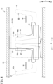
FIG. 4 is a view showing ashielding device 50 provided in thepassenger cabin 28. - The moving
object 10 further includes ashielding device 50. The shieldingdevice 50 includes afirst partition 52, asecond partition 54, and amain body 56. Thefirst partition 52 is a partition for shielding between thefirst seat 38 and thethird seat 42. Thesecond partition 54 is a partition for shielding between thesecond seat 40 and thefourth seat 44. Thefirst partition 52 and thesecond partition 54 can be retracted in themain body 56.FIG. 4 shows theshielding device 50 with thefirst partition 52 and thesecond partition 54 retracted in themain body 56. - The
main body 56 includes a housing capable of accommodating thefirst partition 52 and thesecond partition 54, and an actuator (not shown). The actuator deploys (projects) thefirst partition 52. That is, thefirst partition 52 accommodated in themain body 56 moves in the front direction Z1 in response to the driving of the actuator. - As a result, as shown in
FIGS. 2 and3 , thefirst partition 52 shields between thefirst seat 38 and thethird seat 42. As a result, the possibility that the first passenger's eyes and the third passenger's eyes may meet is further reduced. Thefirst partition 52 positioned between thefirst seat 38 and thethird seat 42 can be accommodated in themain body 56 again by moving in the rearward direction Z2 in response to the driving of the actuator. - The
second partition 54 is also deployed (projected) by an actuator (not shown) provided in themain body 56. That is, thesecond partition 54 accommodated in themain body 56 moves in the rearward direction Z2 in response to the driving of the actuator. - As a result, as shown in
FIGS. 2 and3 , thesecond partition 54 shields between thesecond seat 40 and thefourth seat 44. As a result, the possibility that the second passenger's eyes and the fourth passenger's eyes may meet is further reduced. Thesecond partition 54 positioned between thesecond seat 40 and thefourth seat 44 can be accommodated in themain body 56 again by moving in the front direction Z1 in response to the driving of the actuator. - The actuator provided in the
main body 56 includes, for example, a motor, but is not limited thereto. The actuator can be controlled by a computer (not shown). The computer (not shown) may be provided in the movingobject 10. The actuator may be driven in response to operation of a switch appropriately disposed around thefirst seat 38 or thesecond seat 40. A first actuator for moving thefirst partition 52 and a second actuator for moving thesecond partition 54 may be provided in themain body 56. In addition, one of thefirst partition 52 and thesecond partition 54 may be omitted. - As shown in
FIG. 2 , the movingobject 10 further includes a first table 58, a second table 60, a third table 62, and a fourth table 64. Each of the first table 58 and the second table 60 is, for example, a rectangular table, but is not limited thereto. Each of the third table 62 and the fourth table 64 is a circular table, but is not limited thereto. At least one of the first table 58, the second table 60, the third table 62, or the fourth table 64 may be omitted. - The first table 58 is a table used by the first passenger. The second table 60 is a table used by the second passenger. Each of the first table 58 and the second table 60 is, for example, a folding table that can be accommodated in the
second side wall 26. - The
second side wall 26 is provided with an accommodation portion (first accommodation portion) (not shown) capable of accommodating the first table 58. The first accommodation portion is, for example, a concave portion capable of accommodating the folded first table 58. - The
second side wall 26 is provided with an accommodation portion (second accommodation portion) (not shown) capable of accommodating the second table 60. The second accommodation portion is, for example, a concave portion capable of accommodating the folded second table 60. - The third table 62 is a table used by the third passenger. The fourth table 64 is a table used by the fourth passenger. Each of the third table 62 and the fourth table 64 is, for example, a folding table that can be accommodated in the
doorway door 22. - The
doorway door 22 or thefirst side wall 24 is provided with an accommodation portion (third accommodation portion) (not shown) capable of accommodating the third table 62. The third accommodation portion is, for example, a concave portion capable of accommodating the folded third table 62. - Further, the
doorway door 22 or thefirst side wall 24 is provided with an accommodation portion (fourth accommodation portion) (not shown) capable of accommodating the fourth table 64. The fourth accommodation portion is, for example, a concave portion capable of accommodating the folded fourth table 64. - The third table 62 and the fourth table 64 may be attached to the
first side wall 24. - With respect to the above disclosure, the following appendixes are further disclosed.
- The moving object (10) according to the present disclosure includes the passenger cabin (28). The passenger cabin is defined by the first side wall (24) positioned on one side with respect to the center line (LA) of the moving object and the second side wall (26) positioned on another side with respect to the center line, the center line extending in the front-rear direction (Z). The doorway (20) through which a passenger enters and exits the passenger cabin is formed in the first side wall. The moving object further includes: the first seat (38) located between the center line and the second side wall and disposed to face forward; and the second seat (40) positioned between the center line and the second side wall and disposed rearward of the first seat, the second seat being disposed to face rearward. At least a part of the first seat and at least a part of the second seat overlap the doorway in a side view. Thus, the first passenger seated on the first seat and the second passenger seated on the second seat do not face each other. Therefore, the first passenger's eyes and the second passenger's eyes are unlikely to meet.
- The moving object according to Appendix 1 may further include the third seat (42) disposed between the center line and the first side wall, and on the front side of the doorway; and the fourth seat (44) disposed between the center line and the first side wall, and on the rear side of the doorway, wherein the third seat may face obliquely rearward in the top view, and the fourth seat may face obliquely forward in the top view. With this configuration, the third passenger is less likely to be in the field of view of the first passenger seated on the first seat, and the fourth passenger is less likely to be in the field of view of the second passenger seated on the second seat.
- In the moving object according to Appendix 2, one of the third seat and the fourth seat may be inclined toward the first side wall in the top view, and another of the third seat and the fourth seat may be inclined toward the second side wall in the top view. With this configuration, the legs of the third passenger seated on the third seat and the legs of the fourth passenger seated on the fourth seat are less likely to interfere with each other.
- The moving object according to any one of Appendixes 1 to 3 may further include the partition (52, 54) disposed at least one of between the first seat and the third seat or between the second seat and the fourth seat. This further reduces the possibility that the first passenger's eyes and the third passenger's eyes can meet, and further reduces the possibility that the second passenger's eyes and the fourth passenger's eyes can meet.
- In the moving object according to any one of Appendixes 1 to 4, the passenger cabin may include the aisle extending along the center line, the moving object may further include the cockpit (30) disposed forward of the passenger cabin and communicating with the passenger cabin via the communication passage (36), and the position of the aisle in the widthwise direction (X) orthogonal to the front-rear direction may be different from the position of the communication passage in the widthwise direction. Thus, the passenger doorway and the crew doorway are consolidated into one doorway, and the possibility that the passenger may get lost into the cockpit is reduced.
- In the moving object according to any one of Appendixes 1 to 5, at least one of the first table (58) used by a passenger seated on the first seat or the second table (60) used by a passenger seated on the second seat may be attached to the second side wall. This can give facilities to passengers.
- The moving object according to any one of Appendixes 1 to 6 may further include the doorway door (22) provided at the doorway, and at least one of the third table (62) used by a passenger seated on the third seat or the fourth table (64) used by a passenger seated on the fourth seat may be accommodated in the doorway door so as to be extractable. Thus, the third table and the fourth table do not hinder the passengers and the crew from getting on and off the moving object through the doorway.
- In the moving object according to any one of Appendixes 1 to 7, the moving object may be an aircraft. The aircraft is, for example, an eVTOL, a small jet (airplane), a helicopter, or the like.
Claims (8)
- A moving object (10) comprising a passenger cabin (28), whereinthe passenger cabin is defined by a first side wall (24) positioned on one side with respect to a center line (LA) of the moving object and a second side wall (26) positioned on another side with respect to the center line, the center line extending in a front-rear direction (Z),a doorway (20) through which a passenger enters and exits the passenger cabin is formed in the first side wall,wherein the moving object further comprises:a first seat (38) positioned between the center line and the second side wall and disposed to face forward; anda second seat (40) positioned between the center line and the second side wall, and rearward of the first seat, the second seat being disposed to face rearward, andwhereinat least a part of the first seat and at least a part of the second seat overlap the doorway in a side view.
- The moving object according to claim 1, further comprising:a third seat (42) disposed between the center line and the first side wall, and on a front side of the doorway; anda fourth seat (44) disposed between the center line and the first side wall, and on a rear side of the doorway,whereinthe third seat faces obliquely rearward in a top view, and the fourth seat faces obliquely forward in the top view.
- The moving object according to claim 2, whereinone of the third seat and the fourth seat is inclined toward the first side wall in the top view, andanother of the third seat and the fourth seat is inclined toward the second side wall in the top view.
- The moving object according to claim 2 or 3, further comprising:
a partition (52, 54) disposed at least one of between the first seat and the third seat or between the second seat and the fourth seat. - The moving object according to any one of claims 1 to 4, whereinthe passenger cabin includes an aisle extending along the center line,the moving object further comprises a cockpit (30) disposed forward of the passenger cabin and communicating with the passenger cabin via a communication passage (36), anda position of the aisle in a widthwise direction (X) orthogonal to the front-rear direction is different from a position of the communication passage in the widthwise direction.
- The moving object according to any one of claims 1 to 5, wherein
at least one of a first table (58) used by a passenger seated on the first seat or a second table (60) used by a passenger seated on the second seat is attached to the second side wall. - The moving object according to any one of claims 2 to 4, further comprising:a doorway door (22) provided at the doorway,wherein at least one of a third table (62) used by a passenger seated on the third seat or a fourth table (64) used by a passenger seated on the fourth seat is accommodated in the doorway door so as to be extractable.
- The moving object according to any one of claims 1 to 7, wherein
the moving object is an aircraft.
Applications Claiming Priority (1)
| Application Number | Priority Date | Filing Date | Title |
|---|---|---|---|
| JP2023014320A JP2024110021A (en) | 2023-02-02 | 2023-02-02 | Mobile |
Publications (2)
| Publication Number | Publication Date |
|---|---|
| EP4410677A1 true EP4410677A1 (en) | 2024-08-07 |
| EP4410677B1 EP4410677B1 (en) | 2025-08-27 |
Family
ID=89834318
Family Applications (1)
| Application Number | Title | Priority Date | Filing Date |
|---|---|---|---|
| EP24155158.9A Active EP4410677B1 (en) | 2023-02-02 | 2024-02-01 | Seat arrangement in a moving object |
Country Status (4)
| Country | Link |
|---|---|
| US (1) | US12384542B2 (en) |
| EP (1) | EP4410677B1 (en) |
| JP (1) | JP2024110021A (en) |
| CN (1) | CN118419257A (en) |
Citations (6)
| Publication number | Priority date | Publication date | Assignee | Title |
|---|---|---|---|---|
| US20090050740A1 (en) * | 2007-08-16 | 2009-02-26 | Airbus | Seating unit for aircraft |
| US20090173825A1 (en) * | 2006-04-10 | 2009-07-09 | Airbus Deutschland Gmbh | Aircraft door with oversizing |
| EP3378770A1 (en) * | 2017-03-20 | 2018-09-26 | Optimares S.p.A. | Seat array, particularly for aircraft |
| CN108791502A (en) * | 2017-04-27 | 2018-11-13 | 佛吉亚汽车内部设备工业公司 | Main cabin and relevant automatically or semi-automatically vehicle |
| US10919631B2 (en) * | 2018-10-29 | 2021-02-16 | Safran Cabin Inc. | Aircraft with multiple doors and multiple zones |
| US11136105B2 (en) | 2017-08-02 | 2021-10-05 | Joby Elevate, Inc. | VTOL aircraft for network system |
Family Cites Families (1)
| Publication number | Priority date | Publication date | Assignee | Title |
|---|---|---|---|---|
| US2710731A (en) * | 1952-06-25 | 1955-06-14 | Glenn L Martin Co | Removable bulkhead for aircraft |
-
2023
- 2023-02-02 JP JP2023014320A patent/JP2024110021A/en active Pending
-
2024
- 2024-01-26 US US18/424,044 patent/US12384542B2/en active Active
- 2024-01-29 CN CN202410119271.2A patent/CN118419257A/en active Pending
- 2024-02-01 EP EP24155158.9A patent/EP4410677B1/en active Active
Patent Citations (6)
| Publication number | Priority date | Publication date | Assignee | Title |
|---|---|---|---|---|
| US20090173825A1 (en) * | 2006-04-10 | 2009-07-09 | Airbus Deutschland Gmbh | Aircraft door with oversizing |
| US20090050740A1 (en) * | 2007-08-16 | 2009-02-26 | Airbus | Seating unit for aircraft |
| EP3378770A1 (en) * | 2017-03-20 | 2018-09-26 | Optimares S.p.A. | Seat array, particularly for aircraft |
| CN108791502A (en) * | 2017-04-27 | 2018-11-13 | 佛吉亚汽车内部设备工业公司 | Main cabin and relevant automatically or semi-automatically vehicle |
| US11136105B2 (en) | 2017-08-02 | 2021-10-05 | Joby Elevate, Inc. | VTOL aircraft for network system |
| US10919631B2 (en) * | 2018-10-29 | 2021-02-16 | Safran Cabin Inc. | Aircraft with multiple doors and multiple zones |
Also Published As
| Publication number | Publication date |
|---|---|
| US12384542B2 (en) | 2025-08-12 |
| EP4410677B1 (en) | 2025-08-27 |
| US20240262507A1 (en) | 2024-08-08 |
| CN118419257A (en) | 2024-08-02 |
| JP2024110021A (en) | 2024-08-15 |
Similar Documents
| Publication | Publication Date | Title |
|---|---|---|
| US11046437B2 (en) | Forward-facing aircraft passenger suite with all aisle access | |
| US20190322371A1 (en) | Aircraft door and privacy panel assemblies | |
| EP2815285B1 (en) | Psu pod assembly and method for using same | |
| EP2872398B1 (en) | Class dividing passenger seat bulkhead | |
| US12234017B2 (en) | Redundant rail and carriage assembly | |
| US10919631B2 (en) | Aircraft with multiple doors and multiple zones | |
| US20190329891A1 (en) | Mini suite emergency egress solutions | |
| US11034452B2 (en) | Aircraft with staggered seating arrangement | |
| JP2008542105A (en) | Long-range aircraft | |
| CN111846243A (en) | Logic control for autonomous and manual locking of overhead bins to improve security | |
| US20230415897A1 (en) | Flexible aircraft privacy door | |
| JP2003104298A (en) | Passenger plane | |
| EP4079639B1 (en) | Deployable cabin attendant seat system | |
| US12582564B2 (en) | Multi-use aircraft monuments with wheelchair accommodations | |
| EP4410677B1 (en) | Seat arrangement in a moving object | |
| CN100548801C (en) | Partitions for aircraft compartments | |
| US12617325B2 (en) | Support device for an aircraft cabin interior layout assembly, related assembly and method | |
| US12291351B2 (en) | Deployable attendant seat aircraft cabin barrier | |
| US11691735B2 (en) | Aircraft bench seat assembly | |
| JP2025003935A (en) | Dual Purpose Washroom Barrier | |
| EP3873809A1 (en) | Aircraft with staggered seating arrangement | |
| WO2020092313A1 (en) | Aircraft with multiple doors and multiple zones | |
| US10183751B2 (en) | Side-facing belted aircraft seats | |
| US12346013B2 (en) | Seats with display systems | |
| US20260070656A1 (en) | Aircraft Cabin Storage Consoles |
Legal Events
| Date | Code | Title | Description |
|---|---|---|---|
| PUAI | Public reference made under article 153(3) epc to a published international application that has entered the european phase |
Free format text: ORIGINAL CODE: 0009012 |
|
| STAA | Information on the status of an ep patent application or granted ep patent |
Free format text: STATUS: REQUEST FOR EXAMINATION WAS MADE |
|
| 17P | Request for examination filed |
Effective date: 20240201 |
|
| AK | Designated contracting states |
Kind code of ref document: A1 Designated state(s): AL AT BE BG CH CY CZ DE DK EE ES FI FR GB GR HR HU IE IS IT LI LT LU LV MC ME MK MT NL NO PL PT RO RS SE SI SK SM TR |
|
| GRAP | Despatch of communication of intention to grant a patent |
Free format text: ORIGINAL CODE: EPIDOSNIGR1 |
|
| STAA | Information on the status of an ep patent application or granted ep patent |
Free format text: STATUS: GRANT OF PATENT IS INTENDED |
|
| GRAJ | Information related to disapproval of communication of intention to grant by the applicant or resumption of examination proceedings by the epo deleted |
Free format text: ORIGINAL CODE: EPIDOSDIGR1 |
|
| STAA | Information on the status of an ep patent application or granted ep patent |
Free format text: STATUS: REQUEST FOR EXAMINATION WAS MADE |
|
| GRAP | Despatch of communication of intention to grant a patent |
Free format text: ORIGINAL CODE: EPIDOSNIGR1 |
|
| STAA | Information on the status of an ep patent application or granted ep patent |
Free format text: STATUS: GRANT OF PATENT IS INTENDED |
|
| GRAJ | Information related to disapproval of communication of intention to grant by the applicant or resumption of examination proceedings by the epo deleted |
Free format text: ORIGINAL CODE: EPIDOSDIGR1 |
|
| STAA | Information on the status of an ep patent application or granted ep patent |
Free format text: STATUS: REQUEST FOR EXAMINATION WAS MADE |
|
| GRAP | Despatch of communication of intention to grant a patent |
Free format text: ORIGINAL CODE: EPIDOSNIGR1 |
|
| STAA | Information on the status of an ep patent application or granted ep patent |
Free format text: STATUS: GRANT OF PATENT IS INTENDED |
|
| INTG | Intention to grant announced |
Effective date: 20250402 |
|
| RAP3 | Party data changed (applicant data changed or rights of an application transferred) |
Owner name: HONDA MOTOR CO., LTD. |
|
| GRAS | Grant fee paid |
Free format text: ORIGINAL CODE: EPIDOSNIGR3 |
|
| GRAA | (expected) grant |
Free format text: ORIGINAL CODE: 0009210 |
|
| STAA | Information on the status of an ep patent application or granted ep patent |
Free format text: STATUS: THE PATENT HAS BEEN GRANTED |
|
| AK | Designated contracting states |
Kind code of ref document: B1 Designated state(s): AL AT BE BG CH CY CZ DE DK EE ES FI FR GB GR HR HU IE IS IT LI LT LU LV MC ME MK MT NL NO PL PT RO RS SE SI SK SM TR |
|
| REG | Reference to a national code |
Ref country code: CH Ref legal event code: EP |
|
| REG | Reference to a national code |
Ref country code: DE Ref legal event code: R096 Ref document number: 602024000518 Country of ref document: DE |
|
| REG | Reference to a national code |
Ref country code: IE Ref legal event code: FG4D |
|
| REG | Reference to a national code |
Ref country code: NL Ref legal event code: MP Effective date: 20250827 |
|
| PG25 | Lapsed in a contracting state [announced via postgrant information from national office to epo] |
Ref country code: IS Free format text: LAPSE BECAUSE OF FAILURE TO SUBMIT A TRANSLATION OF THE DESCRIPTION OR TO PAY THE FEE WITHIN THE PRESCRIBED TIME-LIMIT Effective date: 20251227 |
|
| PG25 | Lapsed in a contracting state [announced via postgrant information from national office to epo] |
Ref country code: NO Free format text: LAPSE BECAUSE OF FAILURE TO SUBMIT A TRANSLATION OF THE DESCRIPTION OR TO PAY THE FEE WITHIN THE PRESCRIBED TIME-LIMIT Effective date: 20251127 |
|
| REG | Reference to a national code |
Ref country code: LT Ref legal event code: MG9D |
|
| PG25 | Lapsed in a contracting state [announced via postgrant information from national office to epo] |
Ref country code: PT Free format text: LAPSE BECAUSE OF FAILURE TO SUBMIT A TRANSLATION OF THE DESCRIPTION OR TO PAY THE FEE WITHIN THE PRESCRIBED TIME-LIMIT Effective date: 20251229 |
|
| PG25 | Lapsed in a contracting state [announced via postgrant information from national office to epo] |
Ref country code: FI Free format text: LAPSE BECAUSE OF FAILURE TO SUBMIT A TRANSLATION OF THE DESCRIPTION OR TO PAY THE FEE WITHIN THE PRESCRIBED TIME-LIMIT Effective date: 20250827 |
|
| PG25 | Lapsed in a contracting state [announced via postgrant information from national office to epo] |
Ref country code: HR Free format text: LAPSE BECAUSE OF FAILURE TO SUBMIT A TRANSLATION OF THE DESCRIPTION OR TO PAY THE FEE WITHIN THE PRESCRIBED TIME-LIMIT Effective date: 20250827 Ref country code: NL Free format text: LAPSE BECAUSE OF FAILURE TO SUBMIT A TRANSLATION OF THE DESCRIPTION OR TO PAY THE FEE WITHIN THE PRESCRIBED TIME-LIMIT Effective date: 20250827 |
|
| PG25 | Lapsed in a contracting state [announced via postgrant information from national office to epo] |
Ref country code: GR Free format text: LAPSE BECAUSE OF FAILURE TO SUBMIT A TRANSLATION OF THE DESCRIPTION OR TO PAY THE FEE WITHIN THE PRESCRIBED TIME-LIMIT Effective date: 20251128 |
|
| PG25 | Lapsed in a contracting state [announced via postgrant information from national office to epo] |
Ref country code: SE Free format text: LAPSE BECAUSE OF FAILURE TO SUBMIT A TRANSLATION OF THE DESCRIPTION OR TO PAY THE FEE WITHIN THE PRESCRIBED TIME-LIMIT Effective date: 20250827 |
|
| PG25 | Lapsed in a contracting state [announced via postgrant information from national office to epo] |
Ref country code: LV Free format text: LAPSE BECAUSE OF FAILURE TO SUBMIT A TRANSLATION OF THE DESCRIPTION OR TO PAY THE FEE WITHIN THE PRESCRIBED TIME-LIMIT Effective date: 20250827 |
|
| PG25 | Lapsed in a contracting state [announced via postgrant information from national office to epo] |
Ref country code: PL Free format text: LAPSE BECAUSE OF FAILURE TO SUBMIT A TRANSLATION OF THE DESCRIPTION OR TO PAY THE FEE WITHIN THE PRESCRIBED TIME-LIMIT Effective date: 20250827 Ref country code: BG Free format text: LAPSE BECAUSE OF FAILURE TO SUBMIT A TRANSLATION OF THE DESCRIPTION OR TO PAY THE FEE WITHIN THE PRESCRIBED TIME-LIMIT Effective date: 20250827 |
|
| PG25 | Lapsed in a contracting state [announced via postgrant information from national office to epo] |
Ref country code: RS Free format text: LAPSE BECAUSE OF FAILURE TO SUBMIT A TRANSLATION OF THE DESCRIPTION OR TO PAY THE FEE WITHIN THE PRESCRIBED TIME-LIMIT Effective date: 20251127 |
|
| PG25 | Lapsed in a contracting state [announced via postgrant information from national office to epo] |
Ref country code: ES Free format text: LAPSE BECAUSE OF FAILURE TO SUBMIT A TRANSLATION OF THE DESCRIPTION OR TO PAY THE FEE WITHIN THE PRESCRIBED TIME-LIMIT Effective date: 20250827 |
|
| REG | Reference to a national code |
Ref country code: AT Ref legal event code: MK05 Ref document number: 1829753 Country of ref document: AT Kind code of ref document: T Effective date: 20250827 |
|
| PG25 | Lapsed in a contracting state [announced via postgrant information from national office to epo] |
Ref country code: SM Free format text: LAPSE BECAUSE OF FAILURE TO SUBMIT A TRANSLATION OF THE DESCRIPTION OR TO PAY THE FEE WITHIN THE PRESCRIBED TIME-LIMIT Effective date: 20250827 |
|
| PG25 | Lapsed in a contracting state [announced via postgrant information from national office to epo] |
Ref country code: DK Free format text: LAPSE BECAUSE OF FAILURE TO SUBMIT A TRANSLATION OF THE DESCRIPTION OR TO PAY THE FEE WITHIN THE PRESCRIBED TIME-LIMIT Effective date: 20250827 |
|
| PGFP | Annual fee paid to national office [announced via postgrant information from national office to epo] |
Ref country code: DE Payment date: 20260123 Year of fee payment: 3 |
|
| PG25 | Lapsed in a contracting state [announced via postgrant information from national office to epo] |
Ref country code: AT Free format text: LAPSE BECAUSE OF FAILURE TO SUBMIT A TRANSLATION OF THE DESCRIPTION OR TO PAY THE FEE WITHIN THE PRESCRIBED TIME-LIMIT Effective date: 20250827 |
|
| PG25 | Lapsed in a contracting state [announced via postgrant information from national office to epo] |
Ref country code: IT Free format text: LAPSE BECAUSE OF FAILURE TO SUBMIT A TRANSLATION OF THE DESCRIPTION OR TO PAY THE FEE WITHIN THE PRESCRIBED TIME-LIMIT Effective date: 20250827 |
|
| PG25 | Lapsed in a contracting state [announced via postgrant information from national office to epo] |
Ref country code: CZ Free format text: LAPSE BECAUSE OF FAILURE TO SUBMIT A TRANSLATION OF THE DESCRIPTION OR TO PAY THE FEE WITHIN THE PRESCRIBED TIME-LIMIT Effective date: 20250827 |
|
| PG25 | Lapsed in a contracting state [announced via postgrant information from national office to epo] |
Ref country code: SK Free format text: LAPSE BECAUSE OF FAILURE TO SUBMIT A TRANSLATION OF THE DESCRIPTION OR TO PAY THE FEE WITHIN THE PRESCRIBED TIME-LIMIT Effective date: 20250827 Ref country code: EE Free format text: LAPSE BECAUSE OF FAILURE TO SUBMIT A TRANSLATION OF THE DESCRIPTION OR TO PAY THE FEE WITHIN THE PRESCRIBED TIME-LIMIT Effective date: 20250827 |