EP4410676A1 - Robot and in-cabin service system - Google Patents
Robot and in-cabin service system Download PDFInfo
- Publication number
- EP4410676A1 EP4410676A1 EP23197892.5A EP23197892A EP4410676A1 EP 4410676 A1 EP4410676 A1 EP 4410676A1 EP 23197892 A EP23197892 A EP 23197892A EP 4410676 A1 EP4410676 A1 EP 4410676A1
- Authority
- EP
- European Patent Office
- Prior art keywords
- robot
- rail
- slider
- fixing portion
- driver
- Prior art date
- Legal status (The legal status is an assumption and is not a legal conclusion. Google has not performed a legal analysis and makes no representation as to the accuracy of the status listed.)
- Granted
Links
Images




Classifications
-
- B—PERFORMING OPERATIONS; TRANSPORTING
- B64—AIRCRAFT; AVIATION; COSMONAUTICS
- B64D—EQUIPMENT FOR FITTING IN OR TO AIRCRAFT; FLIGHT SUITS; PARACHUTES; ARRANGEMENT OR MOUNTING OF POWER PLANTS OR PROPULSION TRANSMISSIONS IN AIRCRAFT
- B64D11/00—Passenger or crew accommodation; Flight-deck installations not otherwise provided for
- B64D11/0007—Devices specially adapted for food or beverage distribution services
-
- B—PERFORMING OPERATIONS; TRANSPORTING
- B25—HAND TOOLS; PORTABLE POWER-DRIVEN TOOLS; MANIPULATORS
- B25J—MANIPULATORS; CHAMBERS PROVIDED WITH MANIPULATION DEVICES
- B25J11/00—Manipulators not otherwise provided for
- B25J11/008—Manipulators for service tasks
-
- B—PERFORMING OPERATIONS; TRANSPORTING
- B25—HAND TOOLS; PORTABLE POWER-DRIVEN TOOLS; MANIPULATORS
- B25J—MANIPULATORS; CHAMBERS PROVIDED WITH MANIPULATION DEVICES
- B25J17/00—Joints
- B25J17/02—Wrist joints
- B25J17/0258—Two-dimensional joints
- B25J17/0275—Universal joints, e.g. Hooke, Cardan, ball joints
-
- B—PERFORMING OPERATIONS; TRANSPORTING
- B25—HAND TOOLS; PORTABLE POWER-DRIVEN TOOLS; MANIPULATORS
- B25J—MANIPULATORS; CHAMBERS PROVIDED WITH MANIPULATION DEVICES
- B25J5/00—Manipulators mounted on wheels or on carriages
- B25J5/02—Manipulators mounted on wheels or on carriages travelling along a guideway
-
- B—PERFORMING OPERATIONS; TRANSPORTING
- B25—HAND TOOLS; PORTABLE POWER-DRIVEN TOOLS; MANIPULATORS
- B25J—MANIPULATORS; CHAMBERS PROVIDED WITH MANIPULATION DEVICES
- B25J9/00—Program-controlled manipulators
- B25J9/10—Program-controlled manipulators characterised by positioning means for manipulator elements
- B25J9/12—Program-controlled manipulators characterised by positioning means for manipulator elements electric
- B25J9/123—Linear actuators
-
- F—MECHANICAL ENGINEERING; LIGHTING; HEATING; WEAPONS; BLASTING
- F16—ENGINEERING ELEMENTS AND UNITS; GENERAL MEASURES FOR PRODUCING AND MAINTAINING EFFECTIVE FUNCTIONING OF MACHINES OR INSTALLATIONS; THERMAL INSULATION IN GENERAL
- F16C—SHAFTS; FLEXIBLE SHAFTS; ELEMENTS OR CRANKSHAFT MECHANISMS; ROTARY BODIES OTHER THAN GEARING ELEMENTS; BEARINGS
- F16C11/00—Pivots; Pivotal connections
- F16C11/04—Pivotal connections
- F16C11/06—Ball-joints; Other joints having more than one degree of angular freedom, i.e. universal joints
Definitions
- the present disclosure relates to a robot configured to safely and automatically deliver or collect an article, such as an in-flight meal, bedding, or the like, in a cabin of a mobility vehicle, and an in-cabin service system including the same.
- a crew member delivers articles such as food, drinks, blankets, cushions, or the like to passengers, and collects garbage, recyclables, or the like from the passengers.
- the crew member may use a manually controlled cart.
- a robot may comprise a rail installed on a ceiling or a side wall of a cabin, a slider configured to move along the rail, a robot arm having one end pivotably connected to the slider, and a tray connected to another end of the robot arm and configured to maintain an orientation so as to be able to support an article.
- An in-cabin service system may comprise a terminal disposed in a cabin, a management server communicatively connected to the terminal, and a robot communicatively connected to the management server and configured to operate according to a signal from the management server.
- the robot may comprise a rail installed on a ceiling or a side wall of a cabin, a slider configured to move along the rail, a robot arm having one end pivotably connected to the slider, and a tray connected to another end of the robot arm and configured to maintain an orientation so as to be able to support an article.
- the present disclosure will be described with reference to an example application to an aerial mobility vehicle having a cabin, but the present disclosure is not limited thereto.
- concepts disclosed herein can also be applied to other types of mobility vehicles, such as to a waterborne mobility vehicle, an underwater mobility vehicle, a land mobility vehicle, or the like, equipped with a cabin and/or an indoor space.
- first, second, and the like may be used to describe various components, but these terms are used only for the purpose of distinguishing one component from another component and do not imply an order, sizes, magnitudes, positions, and/or importance of these components.
- Electrification and/or automation may enable safe and effective automation of delivery and collection of articles, e.g., provided as in-flight service.
- FIG. 1 is a view schematically illustrating an example in which a robot according to an example of the present disclosure is applied in a cabin 1
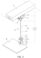
- FIG. 2 is a perspective view illustrating a robot according to an example of the present disclosure.
- a robot according to an example of the present disclosure may include a rail 10, a slider 20 (not visible in FIG. 1 , see FIG. 3B , e.g.), a robot arm 40, and a tray 80.
- FIG. 3 is a perspective view illustrating a rail 10, a slider 20, and an active ball joint 50
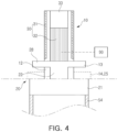
- FIG. 4 is a cross-sectional view illustrating a rail 10 and a slider 20.
- a rail 10 may be disposed on a ceiling and/or a side wall of a cabin 1 in a longitudinal direction of the cabin 1.
- the rail may be at least partially formed of a conductive material, e.g., metal.
- the rail 10 may include a groove portion 11 (e.g., a groove 11 formed in the rail 10) formed to extend in a longitudinal direction of the rail, and through at least one end portion thereof.
- the groove portion 11 may have a substantially cross-shaped cross-section.
- the groove portion 11 may include a main groove 12, and a separation prevention groove 13 formed in a direction intersecting the main groove 12, wherein the main groove 12 and separation prevention groove 13 each extend in the longitudinal direction of the rail 10.
- the main groove 12 may be exposed externally to the rail 10 through an opening in the rail 10 of the groove portion 11.
- a plurality of locking grooves 14 may be disposed at intervals from each other in the longitudinal direction of the rail 10 and may be formed on at least one edge of the groove portion 11.
- the rail 10 is disposed on the ceiling of the cabin 1 is representatively illustrated and described, but is not limited thereto, and for example, the rail 10 may be installed on the side wall of the cabin 1.
- the rail 10 may serve (e.g., be configured) to guide movement of the robot arm 40and/or the tray 80, and may also constitute a portion of a first driver 30 configured to provide a moving force to the robot. Further, since the rail 10 may be configured to be electrically connected to (e.g., to conduct electricity from) a power source, current may be applied to a coil of the first driver 30 through the slider 20.
- the slider 20 may be inserted into the rail 10, for example, the main groove 12 of the groove portion 11, and may slide back and forth in the longitudinal direction of the rail 10 in the groove portion 11 of the rail 11.
- the slider 20 may have a cross-sectional shape corresponding to that of the groove portion 11 of the rail 10.
- the slider 20 may be formed to have a substantially T-shape cross-section. Therefore, the slider 20 may include a support portion 21 having a flat shape (e.g., having a substantially flat surface) and configured to support the robot arm 40 (e.g., connected to the robot arm 40), and an insertion portion 22 connected to the support portion 21 at an angle (e.g., a right angle or otherwise so as to extend from the substantially flat surface of the support portion 21).
- the insertion portion 22 may be configured to be inserted into the main groove 12 of the groove portion 11.
- At least the support portion 21 may have a hollow portion, and may include a position fixing portion 23 configured to extend out of or retract into (e.g., entirely into) the hollow portion.
- at least one through-hole 24 may be formed in one side of the support portion 21 (e.g., a substantially flat surface of the support portion 21).
- the position fixing portion 23 may include a stud 25 (and/or a plurality of studs 25), a frame 26 connected to the stud 25, and a second driver 27 in the hollow portion of the support portion 21 so as to be configured to provide a driving force for moving the frame 26.
- the stud 25 may be, for example, a pillar member having a substantially semicircular cross-section, and may be inserted into a corresponding locking groove while being shape-fitted to one of the plurality of locking grooves 14 of the rail 10.
- a shape of the stud 25 is not limited thereto, and may have any other polygonal, elliptical and/or irregular cross-sectional shape.
- the frame 26 may connect the stud 25 to the second driver 27, and may serve as a stopper preventing the stud 25 from being completely separated from the support portion 21 through the through-hole 24. Also, when a plurality of studs 25 are provided, the frame 26 may connect the plurality of studs 25 such that the studs 25 move integrally (e.g., while maintaining a spatial distribution of the studs 25).
- a rack and a pinion mechanism may be employed as the second driver 27.
- the second driver may include a motor 27a installed on (e.g., connected to) the frame 26, a pinion gear 27b connected to a motor shaft of the motor 27a, and a rack gear 27c in the hollow portion of the support portion 21 and engaged with the pinion gear 27b.
- the pinion gear 27b connected to the motor shaft of the motor 27a rotates by driving force of the motor 27a
- the pinion gear 27b may move along the rack gear 27c while rotating in engagement with the rack gear 27c. Therefore, the frame 26 and the at least one stud 25 may move along with movement of the pinion gear, such that the stud 25 protrudes (e.g., extends) from the support portion 21 through the through-hole 24.
- the protruded stud 25 may be shape-fitted into one of the plurality of locking grooves 14 of the rail 10, and may be inserted into a corresponding locking groove 14, such that a position of the slider 20 relative to the rail 10 may be fixedly determined.
- the motor 27a may rotate in a forward and/or a backward direction upon application of power.
- the stud 25 may be moved the driving force due to an operation of the motor 27a, such that the stud 25 may protrude from (e.g., extend from) a surface of the support portion 21 or be immersed in (e.g., retract into) the hollow portion of the support portion 21.
- the second driver 27 may be provided in pairs to implement a stable operation of the stud 25.
- a configuration of the second driver is not limited to the above-described example, and a fluid pressure cylinder such as a pneumatic cylinder, an electric actuator such as a solenoid actuator, and the like equipped with an operating rod may be employed.
- the insertion portion 22 may include a separation prevention portion 28 formed to protrude in a direction intersecting the movement direction of the slider 20 and configured to be insertable into the separation prevention groove 13 of the groove portion 11.
- the separation prevention portion 28 and the separation prevention groove 13 may prevent the slider 20 from being separated from (or move relative to) the rail 10 in a height and/or width direction of the cabin 1.
- the robot may be continuously and stably supported on the ceiling or the side wall of the cabin 1 for any movement of the mobility vehicle.
- the rail 10 and the slider 20 may form a portion of the first driver 30.
- the first driver 30 of a robot according to an example of the present disclosure may employ a linear motor.
- a plurality of permanent magnets 31 may be arranged on an inner wall of the rail 10 in the longitudinal direction of the rail, and a coil 32 may be wound and/or stacked on the insertion portion 22 of the slider 20.
- the plurality of permanent magnets 31 may be alternately arranged to have different polarities on each inner wall of the rail 10, but may be aligned with permanent magnets on the opposite inner wall such that the same poles face each other.
- Each of the permanent magnets may be fixedly mounted to the rail using any suitable technique, such as an adhesive, a fastener, or the like.
- the coil 32 may be wound and/or stacked on the insertion portion 22 of the slider 20 so as to form a magnetic gap configured to face surfaces of the permanent magnets 31 (e.g., when the slider 20 is inserted in the groove portion 11 of the rail 10).
- a current may be applied to the coil 32 so as to generate a magnetic flux around the coil.
- the current may be applied based on a position of the permanent magnets 31 such that this magnetic flux around the coil interacts with a magnetic flux of the permanent magnet so as to generate an electromagnetic force (e.g., a moving force) . Therefore, the slider 20 may be movable (e.g., linearly) along the rail 10.
- the coil 32 and the permanent magnets 31 may not be in physical contact with each other. A change in magnetic flux may occur when the coil conducts electricity, and thus a moving force may be generated between the coil 32 and the permanent magnets 31.
- a current may be applied to have a positive (+) value, a zero (0) value, or a negative (-) value at regular intervals.
- a direction of the current in the coil 32 may be applied in such a manner as to generate a positive moving force in all coils considering a direction of magnetic flux generated by the permanent magnet 31. As a result, linear movement may be made in a single direction. When reverse movement is required, current may be provided to all coils to create a negative moving force.
- the permanent magnet 31 may be installed on the rail 10 such that a position thereof is fixed, and the coil 32 may be arranged on the slider 20 such that the coil 32 moves with the slider 20, but the disclosure is not limited to this example.
- the coil 32 and the permanent magnet 31 may be arranged opposite to each other such that the permanent magnet 31 moves with the slider 20 while the coil 32 remains stationary with the rail 10.
- the disclosure also encompasses any combination of these arrangements.
- a robot according to an example of the present disclosure may further include a connection terminal 33 mounted on the slider 20 so as to be located between the rail 10 and the slider 20, and configured to contact and slider 20 on the rail 10 and to conduct electricity with the rail 10, through which current flows.
- connection terminal 33 may be formed of a conductor having excellent electrical conductivity, and may be fixedly installed at (e.g., connected to) an end portion of the insertion portion 22 of the slider 20 using any suitable technique, such as an adhesive, a fastener, or the like.
- the connection terminal 33 may be electrically connected to the coil 32.
- the rail 10 may be electrically connected to a power source (not illustrated) such that current may flow from the power source through the rail 10.
- the connection terminal 33 may be in continuous contact with the inner surface of the rail (e.g., with a surface forming the groove portion 11) while sliding along with the slider 20, and the connection terminal 33 may transfer current applied from the rail 10 to the coil 32 through this connection, to supply power to the first driver 30.
- the robot arm 40 may include an active ball joint 50 mounted on the slider 20, an arm member 60 having one end connected to an output shaft 59 of the active ball joint, and a gimbal 70 mounted on the other end of the arm member 60.
- FIG. 5 is a partially exploded perspective view illustrating a main portion of an active ball joint 50.
- An active ball joint 50 may connect a robot arm 40 to a slider 20 movable along a rail 10, and may allow the robot arm 40 to pivot with up to three-axis degree of freedom.
- the active ball joint 50 may utilize a unique interaction between a cross spherical gear 51 and a monopole gear 52.
- the cross spherical gear 51 may have orthogonal teeth formed over a surface of a sphere (e.g., over the entire surface or entire exposed surface), and the monopole gear 52 may be engagement with this type of cross spherical gear.
- the active ball joint 50 may provide high torque transmission and stable positioning, even without a 3D sensor.
- the active ball joint 50 may include a holder 53 fixed to the slider 20 via a bracket 54 and having a concave groove; a cross spherical gear 51 partially accommodated in the concave groove, supported by the holder, having orthogonal teeth formed over a surface thereof (e.g., an entire surface thereof), and having one side fixed to an output shaft 59; a pair of monopole gears 52 engaged on both sides of the cross spherical gear; and a pair of drivers, for example, a third driver 55 and a fourth driver 56, each mounted on the holder 53, and respectively providing driving force to and supporting a corresponding monopole gear 52.
- the cross spherical gear 51 may be formed by molding or processing two axisymmetric tooth structures on a spherical member.
- a first tooth structure may have an involute gear profile projected in an X-Y plane, for example.
- a second tooth structure may be further molded or processed around a Y-axis, such that teeth orthogonal to both axes may be formed on the spherical surface.
- Each of the monopole gears 52 may have a unique tooth structure called a pole P that may be engaged with the cross spherical gear. For example, when a Z-axis is aligned with a rotational axis of the monopole gear 52 and an X-axis is aligned with the pole, then the monopole gear 52 may be symmetrical in the X-Y plane and the cross-section may have an involute gear profile.
- the monopole gear 52 having half the number of teeth and one pole may be engaged with the cross spherical gear indefinitely. This behavior may be illustrated as having a polar orbit for the monopole gear.
- the monopole gear 52 may drive the cross spherical gear 51, when assembled by a differential mechanism. Since the third driver 55 and the fourth driver 56 have the same configuration, only the configuration of the third driver will be described for convenience.
- the third driver 55 may provide a two-axis degree of freedom to the monopole gear 52 using two motors.
- the third driver may include a roll driving motor 55a and a pitch driving motor 55b, such that the monopole gear 52 may roll and pitch. Power for these driving motors may be obtained through a connection terminal 33 contacting the rail 10, through which current flows.
- a differential mechanism may include an internal rotor 55c, a differential internal worm gear 55d, and a differential pinion (not illustrated).
- the internal rotor 55c may rotate about a roll axis by the roll driving motor 55a, and may support a rotational axis of a corresponding monopole gear, for example, a pitch axis (a Z-axis).
- the differential internal worm gear 55d having teeth in a cylinder may rotate about a roll axis by the pitch driving motor 55b.
- the differential pinion mounted on the internal rotor may transmit a force generated by a difference in rotation speed between the internal rotor and the differential inner worm gear, to the monopole gear 52.
- the monopole gear 52 may be provided with a rotational driving force about the roll axis and the pitch axis from the internal rotor 55c and the differential pinion, respectively.
- the active ball joint 50 should have a pair of drivers 55 and 56, and the monopole gear 52 should be engaged with one of the two teeth structures of the cross spherical gear 51, respectively.
- an output shaft 59 fixed to the cross spherical gear 51 may realize pivoting with a three-axis degree of freedom.
- an arm member 60 may perform pivoting with a three-axis degree of freedom.
- the arm member 60 may include a linear actuator equipped with an operating rod 61.
- a linear actuator capable of determining a position of the operating rod with high precision by rotating a ball screw (not illustrated) in a case with a stepping motor mounted on one side of a case 62 may be adopted as the arm member.
- the stepping motor may be configured to rotate forward and/or backward with application of power. Rotational driving of the ball screw according to an operation of the stepping motor may be converted into a linear reciprocating motion of the operating rod screwed into the ball screw. Therefore, the operating rod 61 may expand to protrude away from the case 62 or contract toward a side adjacent to the case 62.
- a controller 90 which will be described later, may be configured to transmit a control signal related to expansion and contraction of the arm member 60 to the stepping motor of the electric linear actuator, based on input positional information or the like, to drive the operation rod 61 of the arm member.
- power of the stepping motor may be obtained through the connection terminal 33 contacting the rail 10 through which current flows.
- An electric linear actuator of the arm member 60 may be any suitable electric linear actuators in any of various configurations.
- a linear actuator using a magnetic force a linear actuator using a piezoelectric effect, or the like, may be employed, as well as a fluid pressure cylinder such as a pneumatic cylinder may be employed.
- a gimbal 70 may be mounted on an end of the arm member 60, for example, an end of the operating rod 61.
- the gimbal may be a multi-axis gimbal 70 having at least three axes.
- the gimbal 70 may be connected to the end of the arm member, and may allow for maintaining a horizontal posture of a tray 80.
- the gimbal 70 may include a plurality of drivers, for example, a fifth driver 72, a sixth driver 74, and a seventh driver 76.
- the fifth driver 72 may be coupled to an end of the arm member 60 so as to be rotatable about a yaw axis parallel to an axial direction of the arm member 60.
- the fifth driver 72 may connect a first fixing portion 71 fixed to the end of the arm member 60, for example, the end of the operating rod 61, and a second fixing portion 73, such that the second fixing portion 73 rotates with respect to the first fixing portion 71 and the end of the arm member 60.
- the sixth driver 74 may be connected to the fifth driver 72 via the second fixing portion 73, and may be rotatably coupled about a roll axis perpendicular to the yaw axis. In this case, the sixth driver 74 may connect the second fixing portion 73 and a third fixing portion 75 to rotate the third fixing portion 75 with respect to the second fixing portion 73.
- the seventh driver 76 may be connected to the sixth driver 74 via the third fixing portion 75, and may be rotatably coupled about a pitch axis perpendicular to the yaw axis and the roll axis.
- the seventh driver may connect the third fixing portion 75 and a fourth fixing portion 77 to rotate the fourth fixing portion with respect to the third fixing portion.
- the fourth fixing portion may be fixedly connected to the tray 80.
- Angles meaning the posture of the tray 80 may be represented by roll, pitch, and yaw.
- the roll means tilting left and right, and the pitch means tilting forward and backward.
- the yaw means turning based on the axial direction of the arm member 60.
- the roll and the pitch may be values indicating how much the tray 80 is tilted relative to a direction of gravity, and an acceleration sensor (not illustrated) and a gyro sensor (not illustrated) may be used to measure the roll and the pitch.
- a value of an axis parallel to the direction of gravity of the gyro sensor may be measured, and this value may be used to calculate a value of the yaw.
- a 3-axis geomagnetic sensor compensating for errors may be applied to measure a yaw direction.
- the controller 90 may transmit a control signal related to the horizontal posture of the tray 80 to each of the fifth to seventh drivers, based on measured values from the acceleration sensor, the gyro sensor, and the like, and rotation angle information of each of the fifth to seventh drivers 72, 74, and 76, to drive the gimbal 70.
- power of the fifth to seventh drivers may be obtained through the connection terminal 33 contacting the rail 10 through which current flows.
- the tray 80 may be a substantially plate-shaped member, and may have a rectangular shape as a whole.
- the tray 80 may be fixedly mounted to the fourth fixing portion 77 of the gimbal 70 by, for example, bonding, bolting, or the like.
- Such a tray 80 may have a size and stiffness capable of supporting an article such as in-flight meals, bedding, or the like.
- FIG. 6 is a view illustrating a modified example of a tray 80.
- a tray 80 may be coupled to a modular box 81, to deliver an article accommodated in the modular box to a passenger.
- At least one insertion groove 82 may be formed across a lower surface of the tray 80, and at least one protrusion 83 may be formed across an upper surface of the modular box 81.
- a cross-sectional shape of the insertion groove 82 may correspond to a cross-sectional shape of the protrusion 83.
- a cross-sectional shape such as a trapezoidal shape called a dovetail, a shape having a stepped portion on at least one side surface, or the like may be employed.
- Arrangement of the insertion groove 82 and the protrusion 83 is not limited to the above example, and an inverse arrangement thereof is possible.
- the protrusion may be formed across the lower surface of the tray 80, and the insertion groove may be formed across the upper surface of the modular box 81.
- the tray 80 When the protrusion 83 of the modular box 81 is inserted into the insertion groove 82 of the tray 80 in a sliding manner, the tray 80 may be coupled to the modular box. The coupling of the tray 80 and the modular box may be undertaken manually by a crew member.
- An insertion groove 84 having the same shape and size as the insertion groove 82 of the tray 80 may be also formed on a lower surface of the modular box 81, such that a plurality of boxes may be stacked. Therefore, the plurality of stacked boxes may be coupled to the tray 80 of a robot according to an example of the present disclosure, and may be transported to a passenger. The plurality of stacked boxes may be separated from the tray 80, and may be stored in a stacked state when not in use.
- a robot according to an example of the present disclosure may further include a controller 90 controlling operations of first to seventh drivers 30, 27, 55, 56, 72, 74, 76 and an electric linear actuator to selectively move a slider 20 of the robot, pivoting and/or expanding or contracting an arm member 60, and allowing a gimbal 70 to maintain a horizontal posture of the tray 80.
- a controller 90 controlling operations of first to seventh drivers 30, 27, 55, 56, 72, 74, 76 and an electric linear actuator to selectively move a slider 20 of the robot, pivoting and/or expanding or contracting an arm member 60, and allowing a gimbal 70 to maintain a horizontal posture of the tray 80.
- the controller 90 may be electrically connected to the first to seventh drivers 30, 27, 55, 56, 72, 74, and 76 and the electric linear actuator through at least one of, for example, wired communication, wireless communication, or wired/wireless communication.
- the controller 90 may be configured to transmit a control signal to each of the drivers and the electric linear actuator through a controller area network (CAN).
- CAN controller area network
- the controller 90 may be implemented as a memory, a microprocessor, and the like.
- the memory may store data for an algorithm or a program reproducing the algorithm for controlling an operation of each component, particularly a corresponding motor.
- the microprocessor may perform predetermined control of each component, particularly a corresponding driver and a corresponding electric linear actuator, using the data stored in the memory.
- the controller 90 may be incorporated into, for example, a control system of a mobility vehicle, or may be used in combination. Such a controller 90 may be configured to control an overall operation of a robot according to an example of the present disclosure.
- the controller 90 may move the slider 20 along a rail 10, to reach the same line as a target seat 2 in a cabin 1 and fix the slider 20 in place.
- the controller 90 may operate an active ball joint 50 of a robot arm 40 to pivot the arm member 60 toward the target seat 2 and fix the arm member 60 to maintain at an appropriate angle.
- the controller 90 may extend an operation rod 61 of the arm member such that the tray 80 approaches the target seat 2.
- the controller 90 may control the gimbal 70 to maintain the horizontal posture of the tray 80, until the robot moves and the tray 80 reaches the target seat 2.
- a robot according to an example of the present disclosure installed in a cabin of a mobility vehicle may be installed on a ceiling or in an upper portion of a side wall in the cabin 1.
- a robot arm 40 and a tray 80, constituting the robot, may move along a rail 10 via a slider 20.
- an unused space such as a ceiling, a side wall, or the like in the cabin 1 may be maximally utilized to ensure comfortable and smooth movement of a passenger in an aisle
- All components of the robot may receive power through the rail 10 through which current flows and a connection terminal 33 contacting the rail.
- the slider 20 may move the robot arm 40 and the tray 80 to a desired position by a first driver 30 receiving power from the rail 10 through the connection terminal 33.
- An active ball joint 50 of the robot arm 40 may be driven by a third driver 55 and a fourth driver 56, to pivot an arm member 60 connected to a cross spherical gear 51 along a hemispherical trajectory, for example.
- the arm member 60 of the robot arm 40 is inclined at an arbitrary angle with respect to the slider 20. Therefore, the tray 80 may be lifted or lowered, as illustrated in FIG. 1 .
- a length of the arm member 60 of the robot arm 40 may be adjusted using a linear actuator equipped with an operating rod 61.
- the arm member 60 may be inclined and contractable to shorten the length, to minimize a space required for moving or storing the robot, and further prevent interference with movement of a passenger when the robot moves.
- the tray 80 may easily access the passenger in an inner seat 2 far from an aisle in the cabin 1. Therefore, the robot may have an advantage of being used for automation and advanced service.
- a gimbal 70 of the robot arm 40 may be driven by fifth to seventh drivers 72, 74, and 76 to maintain the tray 80 fixedly connected to a fourth fixing portion 77 in a horizontal posture at all times (e.g., while supporting an article so as to keep from dropping or disturbing the article) .
- FIG. 7 is a schematic configuration diagram of an in-cabin service system including a robot according to an example of the present disclosure.
- An in-cabin service system may include a terminal 3, a management server 4, and a robot 5.
- the terminal 3 may be disposed on a seat 2 for a passenger or around the seat such that a passenger may order a desired service.
- a plurality of terminals may be provided in the cabin 1.
- the terminal 3 may be various types of portable devices used by the passenger, such as a smartphone, a tablet, a notebook computer, or the like.
- the terminal 3 may be communicatively connected to the management server 4. Specifically, the terminal may access the management server through a wired and/or wireless communication network.
- the terminal may be configured to receive input, e.g., from the passenger, such as information, commands, instructions, or the like.
- the passenger may order a service (e.g., to provide an article such as food, drink, blankets, cushions, or the like) via the terminal 3.
- a service e.g., to provide an article such as food, drink, blankets, cushions, or the like
- the passenger may, via the terminal 3, request the service to collect an article such as garbage, recyclables, or the like, or pay for expenses of a paid service.
- the management server 4 may receive input from the terminal 3 (e.g., passenger request information), and may display the received information on a display 4a.
- the management server may determine a stock amount (e.g., number) of products in real time, and may display stock amount information on the display.
- the management server 4 may be communicatively connected to a controller 90 of the robot 5 via a wired and/or wireless communication network. Therefore, according to an operation of a crew member, the management server 4 may output a signal commanding an operation of the robot to the controller of the robot, or may receive information about a location or state of the robot, and may display the same on the display 4a.
- the crew member may check contents such as a passenger's order or request displayed on the display 4a of the management server 4, and may set an article on a tray 80 of the robot. As necessary, the crew member may couple a modular box 81 to the tray 80.
- the crew member may manipulate the management server 4 to input coordinates of the target seat 2, and command the operation of the robot 5. According to a command signal received from the controller 90, the robot may perform the above-described operation to provide a desired service to the passenger.
- the crew member may remove the article collected by the robot from the tray 80.
- An aspect of the present disclosure is to provide a robot safely and automatically delivering or collecting an article such as in-flight meals, bedding, or the like in a cabin of a mobility vehicle, and an in-cabin service system including the same.
- a robot includes a rail installed on a ceiling or a side wall in a cabin; a slider movably installed along the rail; a robot arm having one end pivotably installed on the slider; and a tray connected to the other end of the robot arm to maintain horizontality, and supporting an article.
- the robot may further include a first driver installed on the rail and the slider to provide a moving force of the slider, wherein the first driver may be a linear motor, and one of the rail or the slider may include a plurality of permanent magnets arranged in a longitudinal direction, and a coil may be wound or stacked on the other thereof.
- the first driver may be a linear motor
- one of the rail or the slider may include a plurality of permanent magnets arranged in a longitudinal direction, and a coil may be wound or stacked on the other thereof.
- the rail may include a groove portion formed to extend in a longitudinal direction of the rail, the groove portion may include a main groove, and a separation prevention groove formed in a direction intersecting the main groove and extending in the longitudinal direction of the rail, the slider may include a support portion having a flat shape and supporting the robot arm, and an insertion portion connected to the support portion at a right angle and inserted into the main groove, and the insertion portion may include a separation prevention portion formed to protrude from the insertion portion and insertable into the separation prevention groove.
- a plurality of locking grooves disposed at intervals from each other in the longitudinal direction of the rail may be formed in at least one edge of the groove portion, and the support portion may include a hollow portion, a position fixing portion installed to be able to appear out of or disappear into the hollow portion, and at least one through-hole formed in one side of the support portion.
- the position fixing portion may include at least one stud, a frame connected to the stud, and a second driver installed in the hollow portion to provide driving force for moving the frame, and the stud may be inserted into one of the plurality of locking grooves through the through-hole.
- the robot may include a connection terminal mounted on the slider to contact and slide on the rail and to conduct electricity with the rail through which current flows, wherein the connection terminal may be electrically connected to the coil.
- the robot arm may include an active ball joint mounted on the slider; an arm member having one end connected to an output shaft of the active ball joint; and a gimbal mounted on the other end of the arm member.
- the active ball joint may include a holder fixed to the slider via a bracket and having a concave groove; a cross spherical gear partially accommodated in the concave groove, supported by the holder, having orthogonal teeth formed over an entire surface thereof, and having one side fixed to the output shaft; a pair of monopole gears engaged on both sides of the cross spherical gear; and a third driver and a fourth driver, mounted on the holder and providing driving force to and supporting a corresponding monopole gear, respectively.
- the third driver and the fourth driver each may include a roll driving motor rolling the corresponding monopole gear, and a pitch driving motor pitching the monopole gear.
- the third driver and the fourth driver each may include an internal rotor rotating about a roll axis by the roll driving motor and supporting a rotational axis of the corresponding monopole gear; a differential internal worm gear rotating about a roll axis by the pitch driving motor and having teeth formed in a cylinder; and a differential pinion mounted on the internal rotor and allowing the monopole gear to rotate about the rotational axis.
- the arm member may include an electric linear actuator equipped with an operating rod.
- the gimbal may include a first fixing portion fixed to an end portion of the operating rod; a fifth driver connecting the first fixing portion and a second fixing portion and rotating the second fixing portion with respect to the first fixing portion; a sixth driver connecting the second fixing portion and a third fixing portion and rotating the third fixing portion with respect to the second fixing portion; and a seventh driver connecting the third fixing portion and a fourth fixing portion and rotating the fourth fixing portion with respect to the third fixing portion, the fourth fixing portion may be fixedly connected to the tray.
- the robot may further include a connection terminal mounted on the slider to contact and slide on the rail and to conduct electricity with the rail through which current flows, wherein the connection terminal may be electrically connected to at least one of the active ball joint, the arm member, or the gimbal.
- an in-cabin service system includes a terminal disposed in a cabin; a management server communicatively connected to the terminal; and the above-described robot communicatively connected to the management server and operating according to a signal from the management server.
- the management server may receive information related to requirements of a passenger input from the terminal, may display the received information on a display, may output a signal commanding an operation of the robot, and may receive information about a position or a state of the robot to display the information on the display.
- an unused space such as a ceiling, a side wall, or the like may be maximally utilized to ensure comfortable and smooth movement of a passenger in an aisle.
Landscapes
- Engineering & Computer Science (AREA)
- Mechanical Engineering (AREA)
- Robotics (AREA)
- General Engineering & Computer Science (AREA)
- Aviation & Aerospace Engineering (AREA)
- Manipulator (AREA)
Abstract
Description
- The present disclosure relates to a robot configured to safely and automatically deliver or collect an article, such as an in-flight meal, bedding, or the like, in a cabin of a mobility vehicle, and an in-cabin service system including the same.
- In the aircraft, a crew member delivers articles such as food, drinks, blankets, cushions, or the like to passengers, and collects garbage, recyclables, or the like from the passengers. The crew member may use a manually controlled cart.
- Providing in-flight services in this manner is cumbersome and slow, and disrupts passenger's comfort and movement in the aisles. In addition, from the aircraft operator's viewpoint, this approach is costly and difficult to maintain at a given quality of service because it depends on the number of passengers and a degree of skill of the crew member.
- The following summary presents a simplified summary of certain features. The summary is not an extensive overview and is not intended to identify key or critical elements.
- Systems, apparatuses, and methods are described for a robot. A robot may comprise a rail installed on a ceiling or a side wall of a cabin, a slider configured to move along the rail, a robot arm having one end pivotably connected to the slider, and a tray connected to another end of the robot arm and configured to maintain an orientation so as to be able to support an article.
- An in-cabin service system may comprise a terminal disposed in a cabin, a management server communicatively connected to the terminal, and a robot communicatively connected to the management server and configured to operate according to a signal from the management server. The robot may comprise a rail installed on a ceiling or a side wall of a cabin, a slider configured to move along the rail, a robot arm having one end pivotably connected to the slider, and a tray connected to another end of the robot arm and configured to maintain an orientation so as to be able to support an article.
- These and other features and advantages are described in greater detail below.
- The above and other aspects, features, and advantages of the present disclosure will be more clearly understood from the following detailed description, taken in conjunction with the accompanying drawings, in which:
-
FIG. 1 is a view schematically illustrating an example in which a robot according to an example of the present disclosure is applied in a cabin. -
FIG. 2 is a perspective view illustrating a robot according to an example of the present disclosure. -
FIG. 3 is a perspective view illustrating a rail, a slider, and an active ball joint. -
FIG. 4 is a cross-sectional view illustrating a rail and a slider. -
FIG. 5 is a partially exploded perspective view illustrating a main portion of an active ball joint. -
FIG. 6 is a view illustrating a modified example of a tray. -
FIG. 7 is a schematic configuration diagram of an in-cabin service system including a robot according to an example of the present disclosure. - Hereinafter, the present disclosure is illustrated in detail with reference to the drawings. In adding reference numerals to components of each of the drawings, it should be noted that the same components have the same numerals as much as possible even if they are displayed on different drawings.
- For convenience of description, the present disclosure will be described with reference to an example application to an aerial mobility vehicle having a cabin, but the present disclosure is not limited thereto. For example, concepts disclosed herein can also be applied to other types of mobility vehicles, such as to a waterborne mobility vehicle, an underwater mobility vehicle, a land mobility vehicle, or the like, equipped with a cabin and/or an indoor space.
- In addition, terms such as first, second, and the like may be used to describe various components, but these terms are used only for the purpose of distinguishing one component from another component and do not imply an order, sizes, magnitudes, positions, and/or importance of these components.
- Electrification and/or automation, if achieved effectively and economically, may enable safe and effective automation of delivery and collection of articles, e.g., provided as in-flight service.
-
FIG. 1 is a view schematically illustrating an example in which a robot according to an example of the present disclosure is applied in a cabin 1, andFIG. 2 is a perspective view illustrating a robot according to an example of the present disclosure. - A robot according to an example of the present disclosure may include a
rail 10, a slider 20 (not visible inFIG. 1 , seeFIG. 3B , e.g.), arobot arm 40, and atray 80. -
FIG. 3 is a perspective view illustrating arail 10, aslider 20, and anactive ball joint 50, andFIG. 4 is a cross-sectional view illustrating arail 10 and aslider 20. - A
rail 10 may be disposed on a ceiling and/or a side wall of a cabin 1 in a longitudinal direction of the cabin 1. The rail may be at least partially formed of a conductive material, e.g., metal. Therail 10 may include a groove portion 11 (e.g., a groove 11 formed in the rail 10) formed to extend in a longitudinal direction of the rail, and through at least one end portion thereof. - The groove portion 11 may have a substantially cross-shaped cross-section. The groove portion 11 may include a
main groove 12, and aseparation prevention groove 13 formed in a direction intersecting themain groove 12, wherein themain groove 12 andseparation prevention groove 13 each extend in the longitudinal direction of therail 10. Themain groove 12 may be exposed externally to therail 10 through an opening in therail 10 of the groove portion 11. - In addition, a plurality of
locking grooves 14 may be disposed at intervals from each other in the longitudinal direction of therail 10 and may be formed on at least one edge of the groove portion 11. - An example in which the
rail 10 is disposed on the ceiling of the cabin 1 is representatively illustrated and described, but is not limited thereto, and for example, therail 10 may be installed on the side wall of the cabin 1. - In a robot according to an example of the present disclosure, the
rail 10 may serve (e.g., be configured) to guide movement of the robot arm 40and/or thetray 80, and may also constitute a portion of afirst driver 30 configured to provide a moving force to the robot. Further, since therail 10 may be configured to be electrically connected to (e.g., to conduct electricity from) a power source, current may be applied to a coil of thefirst driver 30 through theslider 20. - The
slider 20 may be inserted into therail 10, for example, themain groove 12 of the groove portion 11, and may slide back and forth in the longitudinal direction of therail 10 in the groove portion 11 of the rail 11. - To this end, the
slider 20 may have a cross-sectional shape corresponding to that of the groove portion 11 of therail 10. For example, theslider 20 may be formed to have a substantially T-shape cross-section. Therefore, theslider 20 may include asupport portion 21 having a flat shape (e.g., having a substantially flat surface) and configured to support the robot arm 40 (e.g., connected to the robot arm 40), and aninsertion portion 22 connected to thesupport portion 21 at an angle (e.g., a right angle or otherwise so as to extend from the substantially flat surface of the support portion 21). Theinsertion portion 22 may be configured to be inserted into themain groove 12 of the groove portion 11. - At least the
support portion 21 may have a hollow portion, and may include aposition fixing portion 23 configured to extend out of or retract into (e.g., entirely into) the hollow portion. To this end, at least one through-hole 24 may be formed in one side of the support portion 21 (e.g., a substantially flat surface of the support portion 21). - The
position fixing portion 23 may include a stud 25 (and/or a plurality of studs 25), aframe 26 connected to thestud 25, and asecond driver 27 in the hollow portion of thesupport portion 21 so as to be configured to provide a driving force for moving theframe 26. - The
stud 25 may be, for example, a pillar member having a substantially semicircular cross-section, and may be inserted into a corresponding locking groove while being shape-fitted to one of the plurality oflocking grooves 14 of therail 10. A shape of thestud 25 is not limited thereto, and may have any other polygonal, elliptical and/or irregular cross-sectional shape. - The
frame 26 may connect thestud 25 to thesecond driver 27, and may serve as a stopper preventing thestud 25 from being completely separated from thesupport portion 21 through the through-hole 24. Also, when a plurality ofstuds 25 are provided, theframe 26 may connect the plurality ofstuds 25 such that thestuds 25 move integrally (e.g., while maintaining a spatial distribution of the studs 25). - A rack and a pinion mechanism may be employed as the
second driver 27. For example, the second driver may include amotor 27a installed on (e.g., connected to) theframe 26, apinion gear 27b connected to a motor shaft of themotor 27a, and arack gear 27c in the hollow portion of thesupport portion 21 and engaged with thepinion gear 27b. - When the
pinion gear 27b connected to the motor shaft of themotor 27a rotates by driving force of themotor 27a, thepinion gear 27b may move along therack gear 27c while rotating in engagement with therack gear 27c. Therefore, theframe 26 and the at least onestud 25 may move along with movement of the pinion gear, such that thestud 25 protrudes (e.g., extends) from thesupport portion 21 through the through-hole 24. - The protruded
stud 25 may be shape-fitted into one of the plurality oflocking grooves 14 of therail 10, and may be inserted into acorresponding locking groove 14, such that a position of theslider 20 relative to therail 10 may be fixedly determined. - The
motor 27a may rotate in a forward and/or a backward direction upon application of power. Thestud 25 may be moved the driving force due to an operation of themotor 27a, such that thestud 25 may protrude from (e.g., extend from) a surface of thesupport portion 21 or be immersed in (e.g., retract into) the hollow portion of thesupport portion 21. - The
second driver 27 may be provided in pairs to implement a stable operation of thestud 25. A configuration of the second driver is not limited to the above-described example, and a fluid pressure cylinder such as a pneumatic cylinder, an electric actuator such as a solenoid actuator, and the like equipped with an operating rod may be employed. - The
insertion portion 22 may include aseparation prevention portion 28 formed to protrude in a direction intersecting the movement direction of theslider 20 and configured to be insertable into theseparation prevention groove 13 of the groove portion 11. - When a robot according to an example of the present disclosure is installed on the ceiling or the side wall of the cabin 1, the
separation prevention portion 28 and theseparation prevention groove 13 may prevent theslider 20 from being separated from (or move relative to) therail 10 in a height and/or width direction of the cabin 1. - In this manner, the robot may be continuously and stably supported on the ceiling or the side wall of the cabin 1 for any movement of the mobility vehicle.
- In a robot according to an example of the present disclosure, the
rail 10 and theslider 20 may form a portion of thefirst driver 30. For example, thefirst driver 30 of a robot according to an example of the present disclosure may employ a linear motor. - To this end, a plurality of
permanent magnets 31 may be arranged on an inner wall of therail 10 in the longitudinal direction of the rail, and acoil 32 may be wound and/or stacked on theinsertion portion 22 of theslider 20. - The plurality of
permanent magnets 31 may be alternately arranged to have different polarities on each inner wall of therail 10, but may be aligned with permanent magnets on the opposite inner wall such that the same poles face each other. Each of the permanent magnets may be fixedly mounted to the rail using any suitable technique, such as an adhesive, a fastener, or the like. - The
coil 32 may be wound and/or stacked on theinsertion portion 22 of theslider 20 so as to form a magnetic gap configured to face surfaces of the permanent magnets 31 (e.g., when theslider 20 is inserted in the groove portion 11 of the rail 10). A current may be applied to thecoil 32 so as to generate a magnetic flux around the coil. The current may be applied based on a position of thepermanent magnets 31 such that this magnetic flux around the coil interacts with a magnetic flux of the permanent magnet so as to generate an electromagnetic force (e.g., a moving force) . Therefore, theslider 20 may be movable (e.g., linearly) along therail 10. - The
coil 32 and thepermanent magnets 31 may not be in physical contact with each other. A change in magnetic flux may occur when the coil conducts electricity, and thus a moving force may be generated between thecoil 32 and thepermanent magnets 31. - For example, a current may be applied to have a positive (+) value, a zero (0) value, or a negative (-) value at regular intervals. A direction of the current in the
coil 32 may be applied in such a manner as to generate a positive moving force in all coils considering a direction of magnetic flux generated by thepermanent magnet 31. As a result, linear movement may be made in a single direction. When reverse movement is required, current may be provided to all coils to create a negative moving force. - In a robot according to an example of the present disclosure, the
permanent magnet 31 may be installed on therail 10 such that a position thereof is fixed, and thecoil 32 may be arranged on theslider 20 such that thecoil 32 moves with theslider 20, but the disclosure is not limited to this example. For example, thecoil 32 and thepermanent magnet 31 may be arranged opposite to each other such that thepermanent magnet 31 moves with theslider 20 while thecoil 32 remains stationary with therail 10. The disclosure also encompasses any combination of these arrangements. - A robot according to an example of the present disclosure may further include a
connection terminal 33 mounted on theslider 20 so as to be located between therail 10 and theslider 20, and configured to contact andslider 20 on therail 10 and to conduct electricity with therail 10, through which current flows. - The
connection terminal 33 may be formed of a conductor having excellent electrical conductivity, and may be fixedly installed at (e.g., connected to) an end portion of theinsertion portion 22 of theslider 20 using any suitable technique, such as an adhesive, a fastener, or the like. Theconnection terminal 33 may be electrically connected to thecoil 32. - The
rail 10 may be electrically connected to a power source (not illustrated) such that current may flow from the power source through therail 10. Theconnection terminal 33 may be in continuous contact with the inner surface of the rail (e.g., with a surface forming the groove portion 11) while sliding along with theslider 20, and theconnection terminal 33 may transfer current applied from therail 10 to thecoil 32 through this connection, to supply power to thefirst driver 30. - The
robot arm 40 may include an active ball joint 50 mounted on theslider 20, anarm member 60 having one end connected to anoutput shaft 59 of the active ball joint, and agimbal 70 mounted on the other end of thearm member 60. -
FIG. 5 is a partially exploded perspective view illustrating a main portion of an active ball joint 50. - An active ball joint 50 may connect a
robot arm 40 to aslider 20 movable along arail 10, and may allow therobot arm 40 to pivot with up to three-axis degree of freedom. - For pivoting of the
robot arm 40 having a three-axis degree of freedom, the active ball joint 50 may utilize a unique interaction between a crossspherical gear 51 and a monopole gear 52. The crossspherical gear 51 may have orthogonal teeth formed over a surface of a sphere (e.g., over the entire surface or entire exposed surface), and the monopole gear 52 may be engagement with this type of cross spherical gear. - Due to such non-slip gear engagement, the active ball joint 50 may provide high torque transmission and stable positioning, even without a 3D sensor.
- Specifically, the active ball joint 50 may include a
holder 53 fixed to theslider 20 via abracket 54 and having a concave groove; a crossspherical gear 51 partially accommodated in the concave groove, supported by the holder, having orthogonal teeth formed over a surface thereof (e.g., an entire surface thereof), and having one side fixed to anoutput shaft 59; a pair of monopole gears 52 engaged on both sides of the cross spherical gear; and a pair of drivers, for example, athird driver 55 and afourth driver 56, each mounted on theholder 53, and respectively providing driving force to and supporting a corresponding monopole gear 52. - The cross
spherical gear 51 may be formed by molding or processing two axisymmetric tooth structures on a spherical member. First, a first tooth structure may have an involute gear profile projected in an X-Y plane, for example. Then, a second tooth structure may be further molded or processed around a Y-axis, such that teeth orthogonal to both axes may be formed on the spherical surface. - Each of the monopole gears 52 may have a unique tooth structure called a pole P that may be engaged with the cross spherical gear. For example, when a Z-axis is aligned with a rotational axis of the monopole gear 52 and an X-axis is aligned with the pole, then the monopole gear 52 may be symmetrical in the X-Y plane and the cross-section may have an involute gear profile.
- Since two poles of the cross
spherical gear 51 are symmetrical, the monopole gear 52 having half the number of teeth and one pole may be engaged with the cross spherical gear indefinitely. This behavior may be illustrated as having a polar orbit for the monopole gear. - For example, the monopole gear 52 may drive the cross
spherical gear 51, when assembled by a differential mechanism. Since thethird driver 55 and thefourth driver 56 have the same configuration, only the configuration of the third driver will be described for convenience. - The
third driver 55 may provide a two-axis degree of freedom to the monopole gear 52 using two motors. The third driver may include aroll driving motor 55a and apitch driving motor 55b, such that the monopole gear 52 may roll and pitch. Power for these driving motors may be obtained through aconnection terminal 33 contacting therail 10, through which current flows. - A differential mechanism may include an
internal rotor 55c, a differentialinternal worm gear 55d, and a differential pinion (not illustrated). - The
internal rotor 55c may rotate about a roll axis by theroll driving motor 55a, and may support a rotational axis of a corresponding monopole gear, for example, a pitch axis (a Z-axis). The differentialinternal worm gear 55d having teeth in a cylinder may rotate about a roll axis by thepitch driving motor 55b. The differential pinion mounted on the internal rotor may transmit a force generated by a difference in rotation speed between the internal rotor and the differential inner worm gear, to the monopole gear 52. - The monopole gear 52 may be provided with a rotational driving force about the roll axis and the pitch axis from the
internal rotor 55c and the differential pinion, respectively. - The active ball joint 50 should have a pair of
drivers spherical gear 51, respectively. Through this mechanism, anoutput shaft 59 fixed to the crossspherical gear 51 may realize pivoting with a three-axis degree of freedom. - A more detailed configuration and operation of the active ball joint 50 applicable to a robot according to an example of the present disclosure are described in "ABENICS: Active Ball Joint Mechanism With Three-DoF Based on Spherical Gear Meshings" (Kazuki Abe et al.) in IEEE TRANSACTIONS ON ROBOTICS journal (vol. 37, no. 5, pp. 1806-1825, Oct. 2021. This document is hereby incorporated by reference.
- As the arm member may be mounted on the
output shaft 59 of the active ball joint 50, as a result, anarm member 60 may perform pivoting with a three-axis degree of freedom. - The
arm member 60 may include a linear actuator equipped with an operatingrod 61. For example, an electric linear actuator capable of determining a position of the operating rod with high precision by rotating a ball screw (not illustrated) in a case with a stepping motor mounted on one side of acase 62 may be adopted as the arm member. - The stepping motor may be configured to rotate forward and/or backward with application of power. Rotational driving of the ball screw according to an operation of the stepping motor may be converted into a linear reciprocating motion of the operating rod screwed into the ball screw. Therefore, the operating
rod 61 may expand to protrude away from thecase 62 or contract toward a side adjacent to thecase 62. - A
controller 90, which will be described later, may be configured to transmit a control signal related to expansion and contraction of thearm member 60 to the stepping motor of the electric linear actuator, based on input positional information or the like, to drive theoperation rod 61 of the arm member. In addition, power of the stepping motor may be obtained through theconnection terminal 33 contacting therail 10 through which current flows. - An electric linear actuator of the
arm member 60 may be any suitable electric linear actuators in any of various configurations. - In addition to the electric linear actuator, a linear actuator using a magnetic force, a linear actuator using a piezoelectric effect, or the like, may be employed, as well as a fluid pressure cylinder such as a pneumatic cylinder may be employed.
- A
gimbal 70 may be mounted on an end of thearm member 60, for example, an end of the operatingrod 61. The gimbal may be amulti-axis gimbal 70 having at least three axes. Thegimbal 70 may be connected to the end of the arm member, and may allow for maintaining a horizontal posture of atray 80. - For example, the
gimbal 70 may include a plurality of drivers, for example, afifth driver 72, a sixth driver 74, and aseventh driver 76. - The
fifth driver 72 may be coupled to an end of thearm member 60 so as to be rotatable about a yaw axis parallel to an axial direction of thearm member 60. In this case, thefifth driver 72 may connect a first fixingportion 71 fixed to the end of thearm member 60, for example, the end of the operatingrod 61, and asecond fixing portion 73, such that the second fixingportion 73 rotates with respect to the first fixingportion 71 and the end of thearm member 60. - The sixth driver 74 may be connected to the
fifth driver 72 via the second fixingportion 73, and may be rotatably coupled about a roll axis perpendicular to the yaw axis. In this case, the sixth driver 74 may connect the second fixingportion 73 and athird fixing portion 75 to rotate the third fixingportion 75 with respect to the second fixingportion 73. - The
seventh driver 76 may be connected to the sixth driver 74 via the third fixingportion 75, and may be rotatably coupled about a pitch axis perpendicular to the yaw axis and the roll axis. In this case, the seventh driver may connect the third fixingportion 75 and a fourth fixing portion 77 to rotate the fourth fixing portion with respect to the third fixing portion. The fourth fixing portion may be fixedly connected to thetray 80. - Angles meaning the posture of the
tray 80 may be represented by roll, pitch, and yaw. The roll means tilting left and right, and the pitch means tilting forward and backward. The yaw means turning based on the axial direction of thearm member 60. - The roll and the pitch may be values indicating how much the
tray 80 is tilted relative to a direction of gravity, and an acceleration sensor (not illustrated) and a gyro sensor (not illustrated) may be used to measure the roll and the pitch. - For example, a value of an axis parallel to the direction of gravity of the gyro sensor may be measured, and this value may be used to calculate a value of the yaw. Optionally, a 3-axis geomagnetic sensor compensating for errors may be applied to measure a yaw direction.
- The
controller 90, which will be described later, may transmit a control signal related to the horizontal posture of thetray 80 to each of the fifth to seventh drivers, based on measured values from the acceleration sensor, the gyro sensor, and the like, and rotation angle information of each of the fifth toseventh drivers gimbal 70. In addition, power of the fifth to seventh drivers may be obtained through theconnection terminal 33 contacting therail 10 through which current flows. - Since control of such a
gimbal 70 maintaining thetray 80 horizontally has already been known and various types of control have been proposed, a more detailed description of the control of the gimbal will be omitted in this specification. - The
tray 80 may be a substantially plate-shaped member, and may have a rectangular shape as a whole. Thetray 80 may be fixedly mounted to the fourth fixing portion 77 of thegimbal 70 by, for example, bonding, bolting, or the like. Such atray 80 may have a size and stiffness capable of supporting an article such as in-flight meals, bedding, or the like. -
FIG. 6 is a view illustrating a modified example of atray 80. - Optionally, a
tray 80 may be coupled to amodular box 81, to deliver an article accommodated in the modular box to a passenger. - To this end, at least one
insertion groove 82 may be formed across a lower surface of thetray 80, and at least oneprotrusion 83 may be formed across an upper surface of themodular box 81. - A cross-sectional shape of the
insertion groove 82 may correspond to a cross-sectional shape of theprotrusion 83. For example, a cross-sectional shape such as a trapezoidal shape called a dovetail, a shape having a stepped portion on at least one side surface, or the like may be employed. - Arrangement of the
insertion groove 82 and theprotrusion 83 is not limited to the above example, and an inverse arrangement thereof is possible. For example, the protrusion may be formed across the lower surface of thetray 80, and the insertion groove may be formed across the upper surface of themodular box 81. - When the
protrusion 83 of themodular box 81 is inserted into theinsertion groove 82 of thetray 80 in a sliding manner, thetray 80 may be coupled to the modular box. The coupling of thetray 80 and the modular box may be undertaken manually by a crew member. - An
insertion groove 84 having the same shape and size as theinsertion groove 82 of thetray 80 may be also formed on a lower surface of themodular box 81, such that a plurality of boxes may be stacked. Therefore, the plurality of stacked boxes may be coupled to thetray 80 of a robot according to an example of the present disclosure, and may be transported to a passenger. The plurality of stacked boxes may be separated from thetray 80, and may be stored in a stacked state when not in use. - A robot according to an example of the present disclosure may further include a
controller 90 controlling operations of first toseventh drivers slider 20 of the robot, pivoting and/or expanding or contracting anarm member 60, and allowing agimbal 70 to maintain a horizontal posture of thetray 80. - The
controller 90 may be electrically connected to the first toseventh drivers controller 90 may be configured to transmit a control signal to each of the drivers and the electric linear actuator through a controller area network (CAN). - The
controller 90 may be implemented as a memory, a microprocessor, and the like. The memory may store data for an algorithm or a program reproducing the algorithm for controlling an operation of each component, particularly a corresponding motor. The microprocessor may perform predetermined control of each component, particularly a corresponding driver and a corresponding electric linear actuator, using the data stored in the memory. - The
controller 90 may be incorporated into, for example, a control system of a mobility vehicle, or may be used in combination. Such acontroller 90 may be configured to control an overall operation of a robot according to an example of the present disclosure. - For example, the
controller 90 may move theslider 20 along arail 10, to reach the same line as atarget seat 2 in a cabin 1 and fix theslider 20 in place. - The
controller 90 may operate an active ball joint 50 of arobot arm 40 to pivot thearm member 60 toward thetarget seat 2 and fix thearm member 60 to maintain at an appropriate angle. - When the pivoting of the
arm member 60 is completed, thecontroller 90 may extend anoperation rod 61 of the arm member such that thetray 80 approaches thetarget seat 2. - The
controller 90 may control thegimbal 70 to maintain the horizontal posture of thetray 80, until the robot moves and thetray 80 reaches thetarget seat 2. - Hereinafter, an operation of a robot configured as above according to an example of the present disclosure will be described.
- Referring back to
FIG. 1 , a robot according to an example of the present disclosure installed in a cabin of a mobility vehicle may be installed on a ceiling or in an upper portion of a side wall in the cabin 1. Arobot arm 40 and atray 80, constituting the robot, may move along arail 10 via aslider 20. - Due to arrangement of the robot, an unused space such as a ceiling, a side wall, or the like in the cabin 1 may be maximally utilized to ensure comfortable and smooth movement of a passenger in an aisle
- All components of the robot may receive power through the
rail 10 through which current flows and aconnection terminal 33 contacting the rail. - The
slider 20 may move therobot arm 40 and thetray 80 to a desired position by afirst driver 30 receiving power from therail 10 through theconnection terminal 33. - An active ball joint 50 of the
robot arm 40 may be driven by athird driver 55 and afourth driver 56, to pivot anarm member 60 connected to a crossspherical gear 51 along a hemispherical trajectory, for example. - As a result, the
arm member 60 of therobot arm 40 is inclined at an arbitrary angle with respect to theslider 20. Therefore, thetray 80 may be lifted or lowered, as illustrated inFIG. 1 . - In addition, a length of the
arm member 60 of therobot arm 40 may be adjusted using a linear actuator equipped with an operatingrod 61. - In this manner, the
arm member 60 may be inclined and contractable to shorten the length, to minimize a space required for moving or storing the robot, and further prevent interference with movement of a passenger when the robot moves. - In addition, since the
arm member 60 is extended while performing pivoting with a three-axis degree of freedom, thetray 80 may easily access the passenger in aninner seat 2 far from an aisle in the cabin 1. Therefore, the robot may have an advantage of being used for automation and advanced service. - A
gimbal 70 of therobot arm 40 may be driven by fifth toseventh drivers tray 80 fixedly connected to a fourth fixing portion 77 in a horizontal posture at all times (e.g., while supporting an article so as to keep from dropping or disturbing the article) . As such, it is possible to maintain thetray 80 horizontally, such that the robot may stably deliver or collect food or beverages to the passenger even in a shaking environment in which the mobility vehicle is running. -
FIG. 7 is a schematic configuration diagram of an in-cabin service system including a robot according to an example of the present disclosure. - An in-cabin service system may include a
terminal 3, amanagement server 4, and a robot 5. - The
terminal 3 may be disposed on aseat 2 for a passenger or around the seat such that a passenger may order a desired service. A plurality of terminals may be provided in the cabin 1. - However, the present disclosure is not limited thereto, and the
terminal 3 may be various types of portable devices used by the passenger, such as a smartphone, a tablet, a notebook computer, or the like. - The
terminal 3 may be communicatively connected to themanagement server 4. Specifically, the terminal may access the management server through a wired and/or wireless communication network. The terminal may be configured to receive input, e.g., from the passenger, such as information, commands, instructions, or the like. - For example, the passenger may order a service (e.g., to provide an article such as food, drink, blankets, cushions, or the like) via the
terminal 3. Also, or alternatively, the passenger may, via theterminal 3, request the service to collect an article such as garbage, recyclables, or the like, or pay for expenses of a paid service. - The
management server 4 may receive input from the terminal 3 (e.g., passenger request information), and may display the received information on adisplay 4a. The management server may determine a stock amount (e.g., number) of products in real time, and may display stock amount information on the display. - The
management server 4 may be communicatively connected to acontroller 90 of the robot 5 via a wired and/or wireless communication network. Therefore, according to an operation of a crew member, themanagement server 4 may output a signal commanding an operation of the robot to the controller of the robot, or may receive information about a location or state of the robot, and may display the same on thedisplay 4a. - For example, the crew member may check contents such as a passenger's order or request displayed on the
display 4a of themanagement server 4, and may set an article on atray 80 of the robot. As necessary, the crew member may couple amodular box 81 to thetray 80. - The crew member may manipulate the
management server 4 to input coordinates of thetarget seat 2, and command the operation of the robot 5. According to a command signal received from thecontroller 90, the robot may perform the above-described operation to provide a desired service to the passenger. - In a service for collecting an article, when the robot 5 returns to its original position, the crew member may remove the article collected by the robot from the
tray 80. - An aspect of the present disclosure is to provide a robot safely and automatically delivering or collecting an article such as in-flight meals, bedding, or the like in a cabin of a mobility vehicle, and an in-cabin service system including the same.
- According to an aspect of the present disclosure, a robot includes a rail installed on a ceiling or a side wall in a cabin; a slider movably installed along the rail; a robot arm having one end pivotably installed on the slider; and a tray connected to the other end of the robot arm to maintain horizontality, and supporting an article.
- The robot may further include a first driver installed on the rail and the slider to provide a moving force of the slider, wherein the first driver may be a linear motor, and one of the rail or the slider may include a plurality of permanent magnets arranged in a longitudinal direction, and a coil may be wound or stacked on the other thereof.
- The rail may include a groove portion formed to extend in a longitudinal direction of the rail, the groove portion may include a main groove, and a separation prevention groove formed in a direction intersecting the main groove and extending in the longitudinal direction of the rail, the slider may include a support portion having a flat shape and supporting the robot arm, and an insertion portion connected to the support portion at a right angle and inserted into the main groove, and the insertion portion may include a separation prevention portion formed to protrude from the insertion portion and insertable into the separation prevention groove.
- A plurality of locking grooves disposed at intervals from each other in the longitudinal direction of the rail may be formed in at least one edge of the groove portion, and the support portion may include a hollow portion, a position fixing portion installed to be able to appear out of or disappear into the hollow portion, and at least one through-hole formed in one side of the support portion.
- The position fixing portion may include at least one stud, a frame connected to the stud, and a second driver installed in the hollow portion to provide driving force for moving the frame, and the stud may be inserted into one of the plurality of locking grooves through the through-hole.
- The robot may include a connection terminal mounted on the slider to contact and slide on the rail and to conduct electricity with the rail through which current flows, wherein the connection terminal may be electrically connected to the coil.
- The robot arm may include an active ball joint mounted on the slider; an arm member having one end connected to an output shaft of the active ball joint; and a gimbal mounted on the other end of the arm member.
- The active ball joint may include a holder fixed to the slider via a bracket and having a concave groove; a cross spherical gear partially accommodated in the concave groove, supported by the holder, having orthogonal teeth formed over an entire surface thereof, and having one side fixed to the output shaft; a pair of monopole gears engaged on both sides of the cross spherical gear; and a third driver and a fourth driver, mounted on the holder and providing driving force to and supporting a corresponding monopole gear, respectively.
- The third driver and the fourth driver each may include a roll driving motor rolling the corresponding monopole gear, and a pitch driving motor pitching the monopole gear.
- The third driver and the fourth driver each may include an internal rotor rotating about a roll axis by the roll driving motor and supporting a rotational axis of the corresponding monopole gear; a differential internal worm gear rotating about a roll axis by the pitch driving motor and having teeth formed in a cylinder; and a differential pinion mounted on the internal rotor and allowing the monopole gear to rotate about the rotational axis.
- The arm member may include an electric linear actuator equipped with an operating rod.
- The gimbal may include a first fixing portion fixed to an end portion of the operating rod; a fifth driver connecting the first fixing portion and a second fixing portion and rotating the second fixing portion with respect to the first fixing portion; a sixth driver connecting the second fixing portion and a third fixing portion and rotating the third fixing portion with respect to the second fixing portion; and a seventh driver connecting the third fixing portion and a fourth fixing portion and rotating the fourth fixing portion with respect to the third fixing portion, the fourth fixing portion may be fixedly connected to the tray.
- The robot may further include a connection terminal mounted on the slider to contact and slide on the rail and to conduct electricity with the rail through which current flows, wherein the connection terminal may be electrically connected to at least one of the active ball joint, the arm member, or the gimbal.
- According to an aspect of the present disclosure, an in-cabin service system includes a terminal disposed in a cabin; a management server communicatively connected to the terminal; and the above-described robot communicatively connected to the management server and operating according to a signal from the management server.
- The management server may receive information related to requirements of a passenger input from the terminal, may display the received information on a display, may output a signal commanding an operation of the robot, and may receive information about a position or a state of the robot to display the information on the display.
- As described above, according to an example of the present disclosure, there may be an effect of providing a service for stably delivering or collecting an article even under a shaking environment.
- In addition, according to an example of the present disclosure, an unused space such as a ceiling, a side wall, or the like may be maximally utilized to ensure comfortable and smooth movement of a passenger in an aisle.
- In addition, according to an example of the present disclosure, instead of reducing the number of people required for service, it is possible to obtain an effect of increasing economic benefits of an operator by enabling a larger number of passengers to board.
- In addition, according to an example of the present disclosure, since a constant quality of service may be maintained due to automation and since a real-time response to a passenger's request is possible, an effect of improving passenger convenience and upgrading service may also be added.
- While examples have been illustrated and described above, it will be apparent to those skilled in the art that modifications and variations could be made without departing from the scope of the present disclosure as defined by the appended claims.
- Therefore, examples disclosed in the present specification and drawings are not intended to limit the technical spirit of the present disclosure, but to explain, and the scope of the technical spirit of the present disclosure is not limited by the examples. The protection scope of the present disclosure should be construed according to the following claims, and all technical ideas within the equivalent range should be construed as being included in the scope of the present disclosure.
Claims (15)
- A robot comprising:a rail installed on a ceiling or a side wall of a cabin;a slider configured to move along the rail;a robot arm having one end pivotably connected to the slider; anda tray connected to another end of the robot arm and configured to maintain an orientation so as to be able to support an article.
- The robot of claim 1, further comprising a first driver connected to the rail and to the slider and configured to provide a moving force to the slider,wherein the first driver comprises a linear motor, andwherein one of the rail or the slider comprises a plurality of permanent magnets arranged in a longitudinal direction of the rail, and the other of the rail or the slider has a coil wound or stacked thereon.
- The robot of claim 2,wherein the rail forms a groove extending in a longitudinal direction of the rail,wherein the groove comprises a main groove extending in a first direction from a surface of the rail, and a separation prevention groove formed in a second direction so as to intersect with the main groove, wherein each of the main groove and the separation prevention groove extend in the longitudinal direction of the rail,wherein the slider comprises:a support portion having a flat shape and configured to support the robot arm, andan insertion portion connected to the support portion at a non-straight angle and configured to be inserted into the main groove, andwherein the insertion portion comprises a separation prevention portion configured to protrude from the insertion portion so as to be insertable into the separation prevention groove.
- The robot of claim 3,wherein a plurality of locking grooves are formed by at least one edge of the groove so as to be disposed at intervals from each other in the longitudinal direction of the rail, andthe support portion comprises:a hollow portion,a position fixing portion configured to extend out of or retract into the hollow portion, andat least one through-hole formed in one side of the support portion.
- The robot of claim 4,
wherein the position fixing portion comprises:at least one stud,a frame connected to the stud, anda second driver configured to provide driving force for moving the frame, wherein the stud is configured to be inserted into one of the plurality of locking grooves via the through-hole. - The robot of any of claims 2 to 5, further comprising a connection terminal coupled to the slider and configured to electrically connect to and slide on the rail so as to conduct electricity from the rail,
wherein the connection terminal is electrically connected to the coil. - The robot of any of the preceding claims,
wherein the robot arm comprises:an active ball joint mounted on the slider;an arm having one end connected to an output shaft of the active ball joint; anda gimbal mounted on another end of the arm. - The robot of claim 7,
wherein the active ball joint comprises:a holder fixed to the slider via a bracket and having a concave groove;a cross spherical gear that:is partially accommodated in the concave groove,is supported by the holder,comprises orthogonal teeth over a surface thereof, andis fixed to the output shaft at one side;a pair of monopole gears configured to engaged two sides of the cross spherical gear; anda third driver and a fourth driver, mounted on the holder and configured to support and provide driving force to the pair of monopole gears. - The robot of claim 8,
wherein the third driver and the fourth driver each comprise:a roll driving motor configured to roll a corresponding monopole gear of the pair of monopole gears,and a pitch driving motor configured to pitch the corresponding monopole gear. - The robot of claim 9,
wherein the third driver and the fourth driver each further comprise:an internal rotor configured to:be rotated about a roll axis by the roll driving motor, andprovide a rotational axis of the corresponding monopole gear;a differential internal worm gear comprising teeth formed in a cylinder and configured to be rotated about a roll axis by the pitch driving motor; anda differential pinion coupled to the internal rotor and configured to allow the monopole gear to rotate about the rotational axis. - The robot of any of claims 7 to 10,
wherein the arm comprises an electric linear actuator equipped with an operating rod. - The robot of claim 11,
wherein the gimbal comprises:a first fixing portion fixed to an end portion of the operating rod;a fifth driver connected to the first fixing portion and to a second fixing portion and configured to rotate the second fixing portion with respect to the first fixing portion;a sixth driver connected to the second fixing portion and to a third fixing portion and configured to rotate the third fixing portion with respect to the second fixing portion; anda seventh driver connected to the third fixing portion and to a fourth fixing portion and configured to rotate the fourth fixing portion with respect to the third fixing portion,wherein the fourth fixing portion is fixedly connected to the tray. - The robot of any of claims 7 to 12, further comprising a connection terminal coupled to the slider and configured to contact the rail and to conduct electricity from the rail,
wherein the connection terminal is electrically connected to at least one of the active ball joint, the arm, or the gimbal. - An in-cabin service system comprising:a terminal disposed in a cabin;a management server communicatively connected to the terminal; anda robot communicatively connected to the management server and configured to operate according to a signal from the management server, wherein the robot comprises:a rail installed on a ceiling or a side wall of a cabin;a slider configured to move along the rail;a robot arm having one end pivotably connected to the slider; anda tray connected to another end of the robot arm and configured to maintain an orientation so as to be able to support an article.
- The in-cabin service system of claim 14,
wherein the management server is configured to:receive information related to a request, from a passenger, input to the terminal,cause display of the received information by a display,output a signal comprising a command for an operation of the robot, andreceive information about a position or a state of the robot to be displayed by the display.
Applications Claiming Priority (1)
| Application Number | Priority Date | Filing Date | Title |
|---|---|---|---|
| KR1020230013589A KR20240120957A (en) | 2023-02-01 | 2023-02-01 | Serving robot and in-cabin service system including the same |
Publications (2)
| Publication Number | Publication Date |
|---|---|
| EP4410676A1 true EP4410676A1 (en) | 2024-08-07 |
| EP4410676B1 EP4410676B1 (en) | 2025-11-05 |
Family
ID=88093486
Family Applications (1)
| Application Number | Title | Priority Date | Filing Date |
|---|---|---|---|
| EP23197892.5A Active EP4410676B1 (en) | 2023-02-01 | 2023-09-18 | Robot and in-cabin service system |
Country Status (3)
| Country | Link |
|---|---|
| US (1) | US20240253782A1 (en) |
| EP (1) | EP4410676B1 (en) |
| KR (1) | KR20240120957A (en) |
Families Citing this family (1)
| Publication number | Priority date | Publication date | Assignee | Title |
|---|---|---|---|---|
| WO2025059768A1 (en) * | 2023-09-19 | 2025-03-27 | Cobionix Corporation | Autonomous robotic systems for ultrasound examinations |
Citations (3)
| Publication number | Priority date | Publication date | Assignee | Title |
|---|---|---|---|---|
| WO2000046100A2 (en) * | 1999-02-04 | 2000-08-10 | Christopher Mark Volek | Transporting a catering container |
| US20130199402A1 (en) * | 2010-04-19 | 2013-08-08 | P.A. Mohammed Ansar | Inflight catering apparatus |
| DE102017201187A1 (en) * | 2017-01-25 | 2018-07-26 | Deutsches Zentrum für Luft- und Raumfahrt e.V. | Service system for mass transportation |
-
2023
- 2023-02-01 KR KR1020230013589A patent/KR20240120957A/en active Pending
- 2023-07-14 US US18/222,141 patent/US20240253782A1/en active Pending
- 2023-09-18 EP EP23197892.5A patent/EP4410676B1/en active Active
Patent Citations (3)
| Publication number | Priority date | Publication date | Assignee | Title |
|---|---|---|---|---|
| WO2000046100A2 (en) * | 1999-02-04 | 2000-08-10 | Christopher Mark Volek | Transporting a catering container |
| US20130199402A1 (en) * | 2010-04-19 | 2013-08-08 | P.A. Mohammed Ansar | Inflight catering apparatus |
| DE102017201187A1 (en) * | 2017-01-25 | 2018-07-26 | Deutsches Zentrum für Luft- und Raumfahrt e.V. | Service system for mass transportation |
Non-Patent Citations (2)
| Title |
|---|
| ABE KAZUKI ET AL: "ABENICS: Active Ball Joint Mechanism With Three-DoF Based on Spherical Gear Meshings", IEEE TRANSACTIONS ON ROBOTICS, IEEE SERVICE CENTER, PISCATAWAY, NJ, US, vol. 37, no. 5, 26 April 2021 (2021-04-26), pages 1806 - 1825, XP011880700, ISSN: 1552-3098, [retrieved on 20210930], DOI: 10.1109/TRO.2021.3070124 * |
| KAZUKI ABE ET AL.: "ABENICS: Active Ball Joint Mechanism With Three-DoF Based on Spherical Gear Meshings", IEEE TRANSACTIONS ON ROBOTICS JOURNAL, vol. 37, no. 5, October 2021 (2021-10-01), pages 1806 - 1825, XP011880700, DOI: 10.1109/TRO.2021.3070124 |
Also Published As
| Publication number | Publication date |
|---|---|
| US20240253782A1 (en) | 2024-08-01 |
| EP4410676B1 (en) | 2025-11-05 |
| KR20240120957A (en) | 2024-08-08 |
Similar Documents
| Publication | Publication Date | Title |
|---|---|---|
| US12071237B2 (en) | Foldable multi-rotor aerial vehicle | |
| CN110073589B (en) | Transport device with stator for the controlled transport of a transport body relative to the stator | |
| US9789976B2 (en) | Carrier having non-orthogonal axes | |
| US10046844B2 (en) | Aerial vehicle with frame assemblies | |
| US10974830B2 (en) | Manipulation system and method for an aircraft | |
| CN103984193B (en) | Photographing apparatus stabilizer and control method thereof | |
| CN103419190B (en) | Method for determining the possible position of robots arm | |
| CN108332023B (en) | Two-axis and three-axis pan-tilt and shooting equipment thereof | |
| US5903125A (en) | Positioning system | |
| EP3331141A1 (en) | Three degree-of-freedom electromagnetic machine control system and method | |
| US20240253782A1 (en) | Robot and In-Cabin Service System | |
| JP2019142441A (en) | Flight vehicle | |
| US20170254473A1 (en) | Gimbals | |
| EP4261111A1 (en) | Robotic inspection tool for use in confined spaces | |
| KR102548660B1 (en) | Autonomous driving robot for distribution center equipped with wireless charging function | |
| JPH07139603A (en) | Object guide device | |
| Lal et al. | Hardware and control design of a ball balancing robot | |
| KR20170110765A (en) | Control method of boarding type mobile device using the Ball-Robot | |
| Tai et al. | A control of two wheels driven redundant mobile manipulator using a monocular camera system | |
| CN118700114A (en) | Robotic arm, automatic charging device, and control method of automatic charging device | |
| Motonaka | Obstacle avoidance for autonomous locomotion of a quadrotor using an hpf | |
| JP2022128559A (en) | Positioning device for drone | |
| CN110764405A (en) | Multi-angle supported rolling ball control system and method | |
| JPH0471999A (en) | Magnetic torquer |
Legal Events
| Date | Code | Title | Description |
|---|---|---|---|
| PUAI | Public reference made under article 153(3) epc to a published international application that has entered the european phase |
Free format text: ORIGINAL CODE: 0009012 |
|
| STAA | Information on the status of an ep patent application or granted ep patent |
Free format text: STATUS: THE APPLICATION HAS BEEN PUBLISHED |
|
| AK | Designated contracting states |
Kind code of ref document: A1 Designated state(s): AL AT BE BG CH CY CZ DE DK EE ES FI FR GB GR HR HU IE IS IT LI LT LU LV MC ME MK MT NL NO PL PT RO RS SE SI SK SM TR |
|
| STAA | Information on the status of an ep patent application or granted ep patent |
Free format text: STATUS: REQUEST FOR EXAMINATION WAS MADE |
|
| 17P | Request for examination filed |
Effective date: 20240828 |
|
| RBV | Designated contracting states (corrected) |
Designated state(s): AL AT BE BG CH CY CZ DE DK EE ES FI FR GB GR HR HU IE IS IT LI LT LU LV MC ME MK MT NL NO PL PT RO RS SE SI SK SM TR |
|
| REG | Reference to a national code |
Ref country code: DE Ipc: B64D0011000000 Ref legal event code: R079 Ref document number: 602023008259 Country of ref document: DE Free format text: PREVIOUS MAIN CLASS: B64D0011040000 |
|
| GRAP | Despatch of communication of intention to grant a patent |
Free format text: ORIGINAL CODE: EPIDOSNIGR1 |
|
| STAA | Information on the status of an ep patent application or granted ep patent |
Free format text: STATUS: GRANT OF PATENT IS INTENDED |
|
| RIC1 | Information provided on ipc code assigned before grant |
Ipc: B25J 17/02 20060101ALI20250327BHEP Ipc: B25J 11/00 20060101ALI20250327BHEP Ipc: B25J 5/02 20060101ALI20250327BHEP Ipc: B64D 11/00 20060101AFI20250327BHEP |
|
| INTG | Intention to grant announced |
Effective date: 20250414 |
|
| P01 | Opt-out of the competence of the unified patent court (upc) registered |
Free format text: CASE NUMBER: APP_20186/2025 Effective date: 20250428 |
|
| GRAS | Grant fee paid |
Free format text: ORIGINAL CODE: EPIDOSNIGR3 |
|
| GRAA | (expected) grant |
Free format text: ORIGINAL CODE: 0009210 |
|
| STAA | Information on the status of an ep patent application or granted ep patent |
Free format text: STATUS: THE PATENT HAS BEEN GRANTED |
|
| AK | Designated contracting states |
Kind code of ref document: B1 Designated state(s): AL AT BE BG CH CY CZ DE DK EE ES FI FR GB GR HR HU IE IS IT LI LT LU LV MC ME MK MT NL NO PL PT RO RS SE SI SK SM TR |
|
| REG | Reference to a national code |
Ref country code: CH Ref legal event code: F10 Free format text: ST27 STATUS EVENT CODE: U-0-0-F10-F00 (AS PROVIDED BY THE NATIONAL OFFICE) Effective date: 20251105 Ref country code: GB Ref legal event code: FG4D |
|
| REG | Reference to a national code |
Ref country code: DE Ref legal event code: R096 Ref document number: 602023008259 Country of ref document: DE |
|
| REG | Reference to a national code |
Ref country code: IE Ref legal event code: FG4D |
|
| REG | Reference to a national code |
Ref country code: NL Ref legal event code: MP Effective date: 20251105 |
|
| PG25 | Lapsed in a contracting state [announced via postgrant information from national office to epo] |
Ref country code: ES Free format text: LAPSE BECAUSE OF FAILURE TO SUBMIT A TRANSLATION OF THE DESCRIPTION OR TO PAY THE FEE WITHIN THE PRESCRIBED TIME-LIMIT Effective date: 20251105 |
|
| REG | Reference to a national code |
Ref country code: LT Ref legal event code: MG9D |
|
| PG25 | Lapsed in a contracting state [announced via postgrant information from national office to epo] |
Ref country code: NO Free format text: LAPSE BECAUSE OF FAILURE TO SUBMIT A TRANSLATION OF THE DESCRIPTION OR TO PAY THE FEE WITHIN THE PRESCRIBED TIME-LIMIT Effective date: 20260205 |
|
| PG25 | Lapsed in a contracting state [announced via postgrant information from national office to epo] |
Ref country code: FI Free format text: LAPSE BECAUSE OF FAILURE TO SUBMIT A TRANSLATION OF THE DESCRIPTION OR TO PAY THE FEE WITHIN THE PRESCRIBED TIME-LIMIT Effective date: 20251105 Ref country code: HR Free format text: LAPSE BECAUSE OF FAILURE TO SUBMIT A TRANSLATION OF THE DESCRIPTION OR TO PAY THE FEE WITHIN THE PRESCRIBED TIME-LIMIT Effective date: 20251105 Ref country code: AT Free format text: LAPSE BECAUSE OF FAILURE TO SUBMIT A TRANSLATION OF THE DESCRIPTION OR TO PAY THE FEE WITHIN THE PRESCRIBED TIME-LIMIT Effective date: 20251105 |
|
| REG | Reference to a national code |
Ref country code: AT Ref legal event code: MK05 Ref document number: 1854112 Country of ref document: AT Kind code of ref document: T Effective date: 20251105 |
|
| PG25 | Lapsed in a contracting state [announced via postgrant information from national office to epo] |
Ref country code: NL Free format text: LAPSE BECAUSE OF FAILURE TO SUBMIT A TRANSLATION OF THE DESCRIPTION OR TO PAY THE FEE WITHIN THE PRESCRIBED TIME-LIMIT Effective date: 20251105 |
|
| PG25 | Lapsed in a contracting state [announced via postgrant information from national office to epo] |
Ref country code: RS Free format text: LAPSE BECAUSE OF FAILURE TO SUBMIT A TRANSLATION OF THE DESCRIPTION OR TO PAY THE FEE WITHIN THE PRESCRIBED TIME-LIMIT Effective date: 20260205 |
|
| PG25 | Lapsed in a contracting state [announced via postgrant information from national office to epo] |
Ref country code: IS Free format text: LAPSE BECAUSE OF FAILURE TO SUBMIT A TRANSLATION OF THE DESCRIPTION OR TO PAY THE FEE WITHIN THE PRESCRIBED TIME-LIMIT Effective date: 20260305 |
|
| PG25 | Lapsed in a contracting state [announced via postgrant information from national office to epo] |
Ref country code: PT Free format text: LAPSE BECAUSE OF FAILURE TO SUBMIT A TRANSLATION OF THE DESCRIPTION OR TO PAY THE FEE WITHIN THE PRESCRIBED TIME-LIMIT Effective date: 20260305 |
|
| PG25 | Lapsed in a contracting state [announced via postgrant information from national office to epo] |
Ref country code: PL Free format text: LAPSE BECAUSE OF FAILURE TO SUBMIT A TRANSLATION OF THE DESCRIPTION OR TO PAY THE FEE WITHIN THE PRESCRIBED TIME-LIMIT Effective date: 20251105 |
|
| PG25 | Lapsed in a contracting state [announced via postgrant information from national office to epo] |
Ref country code: LV Free format text: LAPSE BECAUSE OF FAILURE TO SUBMIT A TRANSLATION OF THE DESCRIPTION OR TO PAY THE FEE WITHIN THE PRESCRIBED TIME-LIMIT Effective date: 20251105 |
|
| PG25 | Lapsed in a contracting state [announced via postgrant information from national office to epo] |
Ref country code: BG Free format text: LAPSE BECAUSE OF FAILURE TO SUBMIT A TRANSLATION OF THE DESCRIPTION OR TO PAY THE FEE WITHIN THE PRESCRIBED TIME-LIMIT Effective date: 20251105 |