EP4410624A1 - A method of making predictive estimates of the speed of a moving vehicle, corresponding system and computer program product - Google Patents
A method of making predictive estimates of the speed of a moving vehicle, corresponding system and computer program product Download PDFInfo
- Publication number
- EP4410624A1 EP4410624A1 EP24153439.5A EP24153439A EP4410624A1 EP 4410624 A1 EP4410624 A1 EP 4410624A1 EP 24153439 A EP24153439 A EP 24153439A EP 4410624 A1 EP4410624 A1 EP 4410624A1
- Authority
- EP
- European Patent Office
- Prior art keywords
- vehicle
- time window
- value
- observation time
- speed
- Prior art date
- Legal status (The legal status is an assumption and is not a legal conclusion. Google has not performed a legal analysis and makes no representation as to the accuracy of the status listed.)
- Granted
Links
Images


Classifications
-
- B—PERFORMING OPERATIONS; TRANSPORTING
- B60—VEHICLES IN GENERAL
- B60W—CONJOINT CONTROL OF VEHICLE SUB-UNITS OF DIFFERENT TYPE OR DIFFERENT FUNCTION; CONTROL SYSTEMS SPECIALLY ADAPTED FOR HYBRID VEHICLES; ROAD VEHICLE DRIVE CONTROL SYSTEMS FOR PURPOSES NOT RELATED TO THE CONTROL OF A PARTICULAR SUB-UNIT
- B60W40/00—Estimation or calculation of non-directly measurable driving parameters for road vehicle drive control systems not related to the control of a particular sub unit, e.g. by using mathematical models
- B60W40/10—Estimation or calculation of non-directly measurable driving parameters for road vehicle drive control systems not related to the control of a particular sub unit, e.g. by using mathematical models related to vehicle motion
- B60W40/1005—Driving resistance
-
- B—PERFORMING OPERATIONS; TRANSPORTING
- B60—VEHICLES IN GENERAL
- B60W—CONJOINT CONTROL OF VEHICLE SUB-UNITS OF DIFFERENT TYPE OR DIFFERENT FUNCTION; CONTROL SYSTEMS SPECIALLY ADAPTED FOR HYBRID VEHICLES; ROAD VEHICLE DRIVE CONTROL SYSTEMS FOR PURPOSES NOT RELATED TO THE CONTROL OF A PARTICULAR SUB-UNIT
- B60W30/00—Purposes of road vehicle drive control systems not related to the control of a particular sub-unit, e.g. of systems using conjoint control of vehicle sub-units
- B60W30/18—Propelling the vehicle
- B60W30/18009—Propelling the vehicle related to particular drive situations
- B60W30/18072—Coasting
-
- B—PERFORMING OPERATIONS; TRANSPORTING
- B60—VEHICLES IN GENERAL
- B60W—CONJOINT CONTROL OF VEHICLE SUB-UNITS OF DIFFERENT TYPE OR DIFFERENT FUNCTION; CONTROL SYSTEMS SPECIALLY ADAPTED FOR HYBRID VEHICLES; ROAD VEHICLE DRIVE CONTROL SYSTEMS FOR PURPOSES NOT RELATED TO THE CONTROL OF A PARTICULAR SUB-UNIT
- B60W50/00—Details of control systems for road vehicle drive control not related to the control of a particular sub-unit, e.g. process diagnostic or vehicle driver interfaces
- B60W2050/0062—Adapting control system settings
- B60W2050/0075—Automatic parameter input, automatic initialising or calibrating means
- B60W2050/0083—Setting, resetting, calibration
- B60W2050/0088—Adaptive recalibration
-
- B—PERFORMING OPERATIONS; TRANSPORTING
- B60—VEHICLES IN GENERAL
- B60W—CONJOINT CONTROL OF VEHICLE SUB-UNITS OF DIFFERENT TYPE OR DIFFERENT FUNCTION; CONTROL SYSTEMS SPECIALLY ADAPTED FOR HYBRID VEHICLES; ROAD VEHICLE DRIVE CONTROL SYSTEMS FOR PURPOSES NOT RELATED TO THE CONTROL OF A PARTICULAR SUB-UNIT
- B60W2510/00—Input parameters relating to a particular sub-units
- B60W2510/10—Change speed gearings
- B60W2510/1005—Transmission ratio engaged
- B60W2510/101—Transmission neutral state
-
- B—PERFORMING OPERATIONS; TRANSPORTING
- B60—VEHICLES IN GENERAL
- B60W—CONJOINT CONTROL OF VEHICLE SUB-UNITS OF DIFFERENT TYPE OR DIFFERENT FUNCTION; CONTROL SYSTEMS SPECIALLY ADAPTED FOR HYBRID VEHICLES; ROAD VEHICLE DRIVE CONTROL SYSTEMS FOR PURPOSES NOT RELATED TO THE CONTROL OF A PARTICULAR SUB-UNIT
- B60W2520/00—Input parameters relating to overall vehicle dynamics
- B60W2520/10—Longitudinal speed
-
- B—PERFORMING OPERATIONS; TRANSPORTING
- B60—VEHICLES IN GENERAL
- B60W—CONJOINT CONTROL OF VEHICLE SUB-UNITS OF DIFFERENT TYPE OR DIFFERENT FUNCTION; CONTROL SYSTEMS SPECIALLY ADAPTED FOR HYBRID VEHICLES; ROAD VEHICLE DRIVE CONTROL SYSTEMS FOR PURPOSES NOT RELATED TO THE CONTROL OF A PARTICULAR SUB-UNIT
- B60W2530/00—Input parameters relating to vehicle conditions or values, not covered by groups B60W2510/00 or B60W2520/00
- B60W2530/10—Weight
-
- B—PERFORMING OPERATIONS; TRANSPORTING
- B60—VEHICLES IN GENERAL
- B60W—CONJOINT CONTROL OF VEHICLE SUB-UNITS OF DIFFERENT TYPE OR DIFFERENT FUNCTION; CONTROL SYSTEMS SPECIALLY ADAPTED FOR HYBRID VEHICLES; ROAD VEHICLE DRIVE CONTROL SYSTEMS FOR PURPOSES NOT RELATED TO THE CONTROL OF A PARTICULAR SUB-UNIT
- B60W2540/00—Input parameters relating to occupants
- B60W2540/10—Accelerator pedal position
-
- B—PERFORMING OPERATIONS; TRANSPORTING
- B60—VEHICLES IN GENERAL
- B60W—CONJOINT CONTROL OF VEHICLE SUB-UNITS OF DIFFERENT TYPE OR DIFFERENT FUNCTION; CONTROL SYSTEMS SPECIALLY ADAPTED FOR HYBRID VEHICLES; ROAD VEHICLE DRIVE CONTROL SYSTEMS FOR PURPOSES NOT RELATED TO THE CONTROL OF A PARTICULAR SUB-UNIT
- B60W2552/00—Input parameters relating to infrastructure
- B60W2552/15—Road slope, i.e. the inclination of a road segment in the longitudinal direction
-
- B—PERFORMING OPERATIONS; TRANSPORTING
- B60—VEHICLES IN GENERAL
- B60W—CONJOINT CONTROL OF VEHICLE SUB-UNITS OF DIFFERENT TYPE OR DIFFERENT FUNCTION; CONTROL SYSTEMS SPECIALLY ADAPTED FOR HYBRID VEHICLES; ROAD VEHICLE DRIVE CONTROL SYSTEMS FOR PURPOSES NOT RELATED TO THE CONTROL OF A PARTICULAR SUB-UNIT
- B60W2556/00—Input parameters relating to data
- B60W2556/10—Historical data
-
- B—PERFORMING OPERATIONS; TRANSPORTING
- B60—VEHICLES IN GENERAL
- B60W—CONJOINT CONTROL OF VEHICLE SUB-UNITS OF DIFFERENT TYPE OR DIFFERENT FUNCTION; CONTROL SYSTEMS SPECIALLY ADAPTED FOR HYBRID VEHICLES; ROAD VEHICLE DRIVE CONTROL SYSTEMS FOR PURPOSES NOT RELATED TO THE CONTROL OF A PARTICULAR SUB-UNIT
- B60W2720/00—Output or target parameters relating to overall vehicle dynamics
- B60W2720/10—Longitudinal speed
Definitions
- the present invention relates to a method of making predictive estimates of the speed of a moving vehicle, and a related electronic system and computer program product.
- predictive estimates can be used to control a predictive cruise control system (Predictive Economic Cruise Control, PECC).
- PECC Predictive Economic Cruise Control
- An object of one or more embodiments is to provide a method of making predictive estimates of the speed of a moving vehicle with high accuracy, particularly during the eco-roll and cut-off mode phases of motion, so that a predictive cruise control system can be controlled in order to reduce the fuel consumption of the vehicle.
- such an object can be achieved by a method having the features set forth in the claims that follow.
- One or more embodiments may relate to a corresponding electronic system, which may be mounted on board a vehicle.
- One or more embodiments may relate to a corresponding computer program product that can be loaded into the memory of at least one processing circuit (e.g., an electronic control unit or control unit of a vehicle) and comprising portions of software code to execute the steps of the method when the program is executed on the at least one processing circuit.
- a processing circuit e.g., an electronic control unit or control unit of a vehicle
- the reference to such a computer program product is intended to be equivalent to the reference to a computer-readable medium containing instructions for controlling the processing system for the purpose of coordinating the implementation of the method according to one or more embodiments.
- At least one processing circuit is intended to highlight the possibility that one or more embodiments are implemented in a modular and/or distributed form: for example, one or more embodiments may provide for the interaction between multiple electronic control units of the vehicle, such as data detection units (from sensors) and data processing units.
- one or more embodiments relate to a method (possibly implemented on a computer) of making predictive estimates of the speed of a moving vehicle, comprising the following steps:
- the method according to the invention allows the precision of the predictive estimates of the vehicle speed to be refined during use, making the predictive cruise control system more precise in order to reduce fuel consumption.
- the method comprises iteratively repeating the steps i) to vi).
- the step vi) of updating the stored value of the estimated resulting force that acts on the vehicle comprises replacing the stored value of the resulting force with the second value of the resulting force, or updating the stored value of the resulting force by computing a moving average thereof.
- the step iv) of computing an estimate of the final speed of the vehicle as a function of the estimated resulting force that acts on the vehicle during the observation time window comprises:
- the step iv) of computing an estimate of the final speed of the vehicle as a function of the estimated resulting force that acts on the vehicle during the observation time window comprises:
- the method comprises iteratively repeating the steps i) to vi) and storing a plurality of values of the compensation force. Each value in the plurality of values is valid in the vicinity of a certain vehicle speed.
- the method further comprises, at the end of the iterations of the steps i) to vi), computing an estimate of the final speed of the vehicle in the final instant of a further observation time window, as a function of the initial speed of the vehicle in the further time window, a stored value of an estimated resulting force that acts on the vehicle during the further observation time window, the mass of the vehicle and the duration of the further observation time window.
- the stored value of the estimated resulting force that acts on the vehicle during the further observation time window comprises a stored value of the compensation force valid in the vicinity of the initial or final speed of the vehicle in the further time window or in the vicinity of the average speed of the vehicle during the further time window.
- the step of computing an estimate of the final speed of the vehicle at the final instant of a further observation time window comprises interpolating the plurality of values of the compensation force.
- the step i) of detecting whether the vehicle is moving in an eco-roll condition or in a cut-off condition comprises detecting one or more of the following conditions:
- the method comprises:
- the method comprises detecting the slope of the stretch of road traveled by the vehicle during the observation time window via a slope sensor mounted on the vehicle and/or via data received from a GPS navigation system of the vehicle.
- an electronic system for making predictive estimates of the speed of a moving vehicle comprises at least one sensor configured to detect at least one parameter indicative of the dynamic state of the vehicle to detect whether the vehicle is moving in an eco-roll condition or in a cut-off condition, and an electronic control unit configured to carry out the steps of the method according to one or more embodiments.
- the present invention relates to a method for estimating, in a predictive manner, the speed of a moving vehicle to control a predictive cruise control system of the vehicle in order to reduce fuel consumption, as illustrated in Figure 1 which is exemplary of a vehicle V moving along a road R having a certain slope angle ⁇ with respect to the horizontal.
- the method concerns the estimate of the vehicle speed during the so-called “eco-roll” and "cut-off" phases.
- the eco-roll phases are those where the vehicle is moving by inertia with the transmission in neutral (i.e., with the crank shaft decoupled from the drive shaft), only under the action of external forces such as the braking aerodynamic drag force F CD (which is dependent on the speed of the vehicle), the braking rolling resistance force F R , and the component of the weight force parallel to the road F G (which can be braking or propulsive depending on whether the vehicle moves uphill or downhill, and more or less influential depending on the road slope), without being influenced by the resistant force F E due to the friction of the engine and transmission.
- the braking aerodynamic drag force F CD which is dependent on the speed of the vehicle
- the braking rolling resistance force F R the component of the weight force parallel to the road F G (which can be braking or propulsive depending on whether the vehicle moves uphill or downhill, and more or less influential depending on the road slope)
- the cut-off phases are those where the vehicle is moving by inertia with an engaged gear but with the accelerator pedal fully released, in such a way that the engine does not deliver torque but on the contrary is dragged into motion by the rotation of the driving wheels.
- the motion of the vehicle is influenced by the same forces that act during the eco-roll phases (i.e., the aerodynamic drag force F CD , the rolling resistance force F R and the weight force parallel to the road F G ), to which is added a resistant force F E due to the friction of the engine and transmission.
- the values of the parameters C r,E , m, ⁇ , A air , g can be stored in a memory of a vehicle control system, or calculated using known algorithms.
- a default value of the parameter C r,E can be initially stored in the memory
- the value of the mass m can be determined in real time using an estimation algorithm (for example, as described in the Italian patent application No. 102021000026861 filed by the same Applicant, not yet publicly available at the filing date of this application)
- the value of the road slope ⁇ can be detected using a sensor mounted on the vehicle (if it is the current slope), or determined in real time using an estimation algorithm (for example, as described in the Italian patent application No. 102021000026861 cited above), or even obtained from a GPS navigation system (if it concerns the future slope)
- the values A air and g can be stored in memory.
- some embodiments of the present invention relate to an iterative method which allows updating and refining, during use of the vehicle, the value of the parameter C r,E used to make estimates of the future speed of the vehicle during the eco-roll phases.
- a predictive estimate of the vehicle speed is performed using equations 1, 2 and 3 to determine an expected value of the vehicle speed at the end of the eco-roll phase.
- An eco-roll phase can be detected when the vehicle meets the following dynamic conditions: the gear is not engaged (i.e., the vehicle is moving in neutral), no braking system or retarder system of the vehicle is active, and the speed of the vehicle is comprised between a lower threshold value and an upper threshold value.
- the eco-roll phase exceeds the minimum duration, then it is considered "valid" to update the parameter C r,E .
- the eco-roll phase is considered ended when a certain maximum duration is reached, or when the vehicle no longer meets the corresponding dynamic conditions (if this happens before the maximum duration time window finishes).
- the algorithm calculates the value of the speed v sim(n) that is expected at the end of the eco-roll phase using equations 1, 2 and 3, and at the same time performs a new reading of the real speed of the vehicle at the end of the eco-roll phase (for example, again reading this data from the CAN network of the vehicle).
- the value C r,E(n-1) is the default value. If, however, it is a subsequent eco-roll phase (considering that the algorithm can be repeated iteratively during the entire duration of the vehicle journey), the value C r,E(n-1) is the value calculated in the previous iteration.
- the value of the calibration parameter c it is possible to limit the effect of each iteration (for example, c can be set so that the parameter C r,E can be updated at each iteration by no more than 15% more or less than the previous value).
- c can be set so that the parameter C r,E can be updated at each iteration by no more than 15% more or less than the previous value.
- the value of the parameter C r,E can be stored in a memory of a vehicle processing system (for example, an electronic control unit, ECU), such as an EEPROM memory.
- the predictive estimate of the vehicle speed can be improved using a different method, in which the value of the parameter C r,E is kept constant, and a compensation force term is added in equation 3 which is used to estimate the speed according to equation 2.
- the resulting force FR E(n-1) is then given by the sum of the braking rolling resistance force F R , the braking aerodynamic drag force F CD , the component of the weight force parallel to the road Fc, and a compensation force F CMP , as indicated in the following equation 6:
- FR E n ⁇ 1 C r , E ⁇ m ⁇ cos ⁇ n ⁇ 1 + A air ⁇ v sim n ⁇ 1 2 + mg ⁇ sin ⁇ n ⁇ 1 + F CMP
- an expected speed value is calculated at the end of the eco-roll phase (i.e., v sim(n) ), using equations 1, 2 and 6.
- v sim(n) an expected speed value is calculated at the end of the eco-roll phase (i.e., v sim(n) ), using equations 1, 2 and 6.
- F CMP,est of the compensation force is calculated which would have returned, using equations 1, 2 and 6, the value of the real speed v real (n) , according to the following equation 7 (i.e., the value of the compensation force that minimizes - i.e., eliminates or cancels out - the error between the estimated speed and the real speed is calculated):
- F CMP , est v real n ⁇ v sim n ⁇ t E ⁇ m
- the average speed of the vehicle during the respective eco-roll phase is calculated.
- a single value of the parameter C r,E is updated at each eco-roll phase (for example, computing a moving average)
- multiple values of the compensation force F CMP are stored and updated, associated with the average or initial speed of the vehicle during each eco-roll phase.
- an array of data is stored in which, a respective value of the compensation force F CMP (v) (where v indicates the corresponding speed) and the number of occurrences Occ (v) associated with it (i.e., the number of times this value has been updated) are associated to discrete speed values (for example, values spaced at intervals of 5 km/h), as exemplified in the following Table I: Table I Vehicle speed [km/h] 40 45 50 55 60 65 70 75 80 85 90 F CMP F CMP (40) ... ... ... ... ... ... ... ... F CMP (90) Occ OCC (40) ... ... ... ... ... ... ... Occ (90)
- a value of the compensation force F CMP,est according to equation 7 and a corresponding value of average (or initial) speed are calculated.
- the value of the compensation force F CMP,est can be limited to fall within a predefined range of plausible values, thus preventing possible errors in the execution of the algorithm from causing the value to diverge.
- the occurrence value can be limited to a predefined maximum value.
- the array of values can be populated for example as indicated in the following Table II: Table II Vehicle speed [km/h] 40 45 50 55 60 65 70 75 80 85 90 F CMP 0 0 0 0 0 0 800 0 0 0 0 0 Occ 0 0 0 0 0 1 0 0 0 0 0 0 0 0 0
- the array of values can be populated for example as indicated in the following Table III: Table III Vehicle speed [km/h] 40 45 50 55 60 65 70 75 80 85 90 F CMP 0 0 0 0 0 0 800 0 0 300 0 0 Occ 0 0 0 0 0 4 0 0 3 0 0
- the array of values can be populated for example as indicated in the following Table IV: Table IV Vehicle speed [km/h] 40 45 50 55 60 65 70 75 80 85 90 F CMP 0 0 200 0 0 800 0 0 300 0 0 Occ 0 0 1 0 0 4 0 0 3 0 0
- the value of compensation force F CMP stored in the array can be interpolated in order to determine a curve that returns the value of the compensation force as a function of the vehicle speed.
- This value is used in equations 1, 2 and 6 to make predictive estimates of the vehicle speed in the case of motion in eco-roll mode.
- figures 2 , 3 and 4 represent possible linear interpolation curves of the values represented in Tables II, III and IV, respectively. Of course, other types of interpolation are possible (e.g., polynomial).
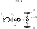
- the motion transmission chain of a vehicle can be schematized by an engine 20 having an output shaft coupled to the first disk of a clutch 22.
- the second disk of the clutch 22 is coupled to the input shaft of a gearbox 24.
- the output shaft of the gearbox 24 is connected to a differential device 26 located on the axle of the driving wheels.
- Two output shafts of the differential device 26 i.e., the axle shafts
- the gear ratio of the gearbox 24 is indicated by g r
- the gear ratio of the differential 26 is indicated by a r
- the radius of the driving wheels 28 is indicated by r.
- the value g r of the gear ratio of the gearbox can be read from a message available on the CAN network of the vehicle (for example, ETC2.TransmActGr).
- the ratio a r /r which is constant, can instead be calculated (only once) as the ratio between the rotation speed of the output shaft of the gearbox 24 and the forward speed of the vehicle, both of these values being readable from available messages on CAN network of the vehicle (respectively, TCO1 .TcoOutSpeed and TCO1.TcoVehSpeed), according to the following equation 13:
- the resulting force FR C(n-1) is given by the sum of the braking rolling resistance force F R (equal to the product between the cut-off rolling resistance coefficient C r,C , the mass m of the vehicle and the cosine of the slope angle ⁇ of the road), the braking aerodynamic drag force F CD , and the component of the weight force parallel to the road Fc.
- the values of the parameters C r,C , m, ⁇ , A air , g can be stored in a memory of a vehicle control system, or calculated using known algorithms.
- a cut-off phase can be detected when the vehicle meets the following dynamic conditions: a gear is engaged and no gear shift is in progress, the accelerator pedal is fully released (i.e., the engine is not providing torque), no braking system or retarder system of the vehicle is active, and the speed of the vehicle is between a lower threshold value and an upper threshold value.
- the cut-off phase is considered ended when a certain maximum duration is reached, or when the vehicle no longer respects the corresponding dynamic conditions (if this occurs before the maximum duration time window finishes).
- the algorithm calculates the value of the speed v sim(n) that is expected at the end of the cut-off phase using equations 1, 10 and 11, and at the same time performs a new reading of the real speed of the vehicle at the end of the cut-off phase.
- the value of the parameter C r,C is updated in order to reduce the error in the speed estimate, for example according to the following equation 16, in which c is a calibration parameter (greater than or equal to 1):
- C r , C n C r , C n ⁇ 1 ⁇ c ⁇ 1 c + C r , C , est ⁇ 1 c
- the value of the parameter C r,C is iteratively updated, using a moving average approach, where each new cut-off phase is used to calculate a value C r,C,est that contributes to the stored value C r,C depending on the value of the calibration parameter c.
- c can be set so that the parameter C r,C can be updated at each iteration by no more than 15% more or less than the previous value.
- the value of the parameter C r,C can be stored in a memory of a vehicle processing system (for example, an electronic control unit, ECU), such as an EEPROM memory.
- a vehicle processing system for example, an electronic control unit, ECU
- ECU electronice control unit
- the predictive estimate of the vehicle speed can be improved using a different method, in which the value of the parameter C r,C is kept constant, and a compensation force term is added in equation 11 which is used to estimate the speed according to equation 10.
- the resulting force F RC(n-1) is therefore given by the sum of the braking rolling resistance force F R , the braking aerodynamic drag force F CD , the component of the weight force parallel to the road Fc, and a compensation force F CMP , as indicated in the following equation 17:
- F CMP compensation force
- an expected speed value is calculated at the end of the cut-off phase (i.e., v sim(n) ), using equations 1, 10 and 17.
- a value F CMP,est of the compensation force is calculated which would have returned, using equations 1, 10 and 17, the value of the real speed v rea / (n) , according to the following equation 18 (i.e., the value of the compensation force that minimizes - i.e., eliminates or cancels out - the error between the estimated speed and the real speed is calculated:
- F CMP , est v real n ⁇ v sim n ⁇ t C ⁇ m
- the average speed of the vehicle during the respective cut-off phase is calculated.
- Multiple values of the compensation force F CMP are stored and updated, in relation to the average or initial speed of the vehicle during each cut-off phase. These values are possibly interpolated and used in equations 1, 10 and 17 in the same way previously discussed for the eco-roll phases.
- the method described here can be implemented in an electronic system that comprises: one or more sensors configured to detect one or more parameters indicative of the dynamic state of the vehicle, and/or a GPS locator configured to provide information regarding a stretch of road that the vehicle is travelling (for example, information on the road slope in the next 2 km), and at least one electronic control unit configured to carry out the steps of the method.
Landscapes
- Engineering & Computer Science (AREA)
- Automation & Control Theory (AREA)
- Transportation (AREA)
- Mechanical Engineering (AREA)
- Physics & Mathematics (AREA)
- Mathematical Physics (AREA)
- Control Of Transmission Device (AREA)
Abstract
i) detecting whether the vehicle (V) is in an eco-roll condition, where the vehicle is moving by inertia with the transmission in neutral, or in a cut-off condition, where the vehicle is moving by inertia with an engaged gear and the accelerator pedal fully released;
ii) if the vehicle (V) is in an eco-roll or cut-off condition, starting an observation time window and sensing the real initial speed (vreal(n-1) ) of the vehicle at an initial instant of the observation time window;
iii) when the vehicle (V) exits the eco-roll or cut-off condition, or when the observation time window reaches a predefined maximum duration, stopping the observation time window and sensing the real final speed (vreal(n) ) of the vehicle at a final instant of the observation time window;
iv) computing an estimate of the final speed (vsim(n) ) of the vehicle at the final instant of the observation time window, as a function of the initial speed (vreal(n-1) ) of the vehicle, a stored value of an estimated resulting force that acts on the vehicle (V) during the observation time window, the mass of the vehicle (V) and the duration of the observation time window;
v) computing a second value of the estimated resulting force that acts on the vehicle (V) during the observation time window, where the second value of the resulting force minimizes the error between the estimate of the final speed (vsim(n) ) of the vehicle and the real final speed (vreal(n) ) of the vehicle; and
vi) updating the stored value of the estimated resulting force that acts on the vehicle (V) as a function of the second value of the resulting force, or storing a corrective factor of the estimated resulting force that acts on the vehicle as a function of the second value of the resulting force.
Description
- The present invention relates to a method of making predictive estimates of the speed of a moving vehicle, and a related electronic system and computer program product. In particular, predictive estimates can be used to control a predictive cruise control system (Predictive Economic Cruise Control, PECC).
- Methods of controlling a predictive cruise control system are known in the art, for example from document
US 2016/0016586 A1 . The predictive cruise control system disclosed in this document uses the values of some state variables of the vehicle, as well as information about the slope profile of a stretch of road that the vehicle is going to travel on, to control the speed of the vehicle. - In order to reduce fuel consumption while the vehicle is moving, improved predictive algorithms that allow the speed of the vehicle to be predicted more accurately under certain conditions are desirable.
- An object of one or more embodiments is to provide a method of making predictive estimates of the speed of a moving vehicle with high accuracy, particularly during the eco-roll and cut-off mode phases of motion, so that a predictive cruise control system can be controlled in order to reduce the fuel consumption of the vehicle.
- According to one or more embodiments, such an object can be achieved by a method having the features set forth in the claims that follow.
- One or more embodiments may relate to a corresponding electronic system, which may be mounted on board a vehicle.
- One or more embodiments may relate to a corresponding computer program product that can be loaded into the memory of at least one processing circuit (e.g., an electronic control unit or control unit of a vehicle) and comprising portions of software code to execute the steps of the method when the program is executed on the at least one processing circuit. As used herein, the reference to such a computer program product is intended to be equivalent to the reference to a computer-readable medium containing instructions for controlling the processing system for the purpose of coordinating the implementation of the method according to one or more embodiments. The reference to "at least one" processing circuit is intended to highlight the possibility that one or more embodiments are implemented in a modular and/or distributed form: for example, one or more embodiments may provide for the interaction between multiple electronic control units of the vehicle, such as data detection units (from sensors) and data processing units.
- The claims are an integral part of the technical teaching provided herein relating to the embodiments.
- According to an aspect of the present invention, one or more embodiments relate to a method (possibly implemented on a computer) of making predictive estimates of the speed of a moving vehicle, comprising the following steps:
- i) detecting whether the vehicle is moving in an eco-roll condition, where the vehicle is moving by inertia with the transmission in neutral, or in a cut-off condition, where the vehicle is moving by inertia with an engaged gear and the accelerator pedal fully released;
- ii) in response to the vehicle being moving in an eco-roll or cut-off condition, starting an observation time window and sensing the real initial speed of the vehicle at an initial instant of the observation time window;
- iii) in response to the vehicle exiting the eco-roll or cut-off condition, or in response to the observation time window reaching a predefined maximum duration, stopping the observation time window and sensing the real final speed of the vehicle at a final instant of the observation time window;
- iv) computing an estimate of the final speed of the vehicle at the final instant of the observation time window, as a function of the initial speed of the vehicle, a stored value of an estimated resulting force that acts on the vehicle during the observation time window, the mass of the vehicle and the duration of the observation time window;
- v) computing a second value of the estimated resulting force that acts on the vehicle during the observation time window, wherein the second value of the resulting force minimizes (e.g., cancels out, eliminates) the error between the estimate of the final speed of the vehicle and the real final speed of the vehicle; and
- vi) updating the stored value of the estimated resulting force that acts on the vehicle as a function of the second value of the resulting force, or storing a corrective factor of the estimated resulting force that acts on the vehicle as a function of the second value of the resulting force.
- Thanks to the aforementioned features, the method according to the invention allows the precision of the predictive estimates of the vehicle speed to be refined during use, making the predictive cruise control system more precise in order to reduce fuel consumption.
- In a preferred embodiment, the method comprises iteratively repeating the steps i) to vi).
- In a preferred embodiment, the step vi) of updating the stored value of the estimated resulting force that acts on the vehicle comprises replacing the stored value of the resulting force with the second value of the resulting force, or updating the stored value of the resulting force by computing a moving average thereof.
- In a preferred embodiment, the step iv) of computing an estimate of the final speed of the vehicle as a function of the estimated resulting force that acts on the vehicle during the observation time window comprises:
- estimating a value of a rolling resistance force as a function of a rolling resistance coefficient, the mass of the vehicle and the slope of the stretch of road traveled by the vehicle during the observation time window;
- estimating a value of an aerodynamic drag force as a function of an aerodynamic drag coefficient of the vehicle and the initial speed of the vehicle; and
- estimating a value of a weight force as a function of the mass of the vehicle and the slope of the stretch of road traveled by the vehicle during the observation time window;
- In a preferred embodiment, the step iv) of computing an estimate of the final speed of the vehicle as a function of the estimated resulting force that acts on the vehicle during the observation time window comprises:
- estimating a value of a rolling resistance force as a function of a rolling resistance coefficient, the mass of the vehicle and the slope of the stretch of road traveled by the vehicle during the observation time window;
- estimating a value of an aerodynamic drag force as a function of an aerodynamic drag coefficient of the vehicle and the initial speed of the vehicle;
- estimating a value of a weight force as a function of the mass of the vehicle and the slope of the stretch of road traveled by the vehicle during the observation time window; and
- estimating a value of a compensation force;
- In a preferred embodiment, the method comprises iteratively repeating the steps i) to vi) and storing a plurality of values of the compensation force. Each value in the plurality of values is valid in the vicinity of a certain vehicle speed. The method further comprises, at the end of the iterations of the steps i) to vi), computing an estimate of the final speed of the vehicle in the final instant of a further observation time window, as a function of the initial speed of the vehicle in the further time window, a stored value of an estimated resulting force that acts on the vehicle during the further observation time window, the mass of the vehicle and the duration of the further observation time window. The stored value of the estimated resulting force that acts on the vehicle during the further observation time window comprises a stored value of the compensation force valid in the vicinity of the initial or final speed of the vehicle in the further time window or in the vicinity of the average speed of the vehicle during the further time window.
- In a preferred embodiment, the step of computing an estimate of the final speed of the vehicle at the final instant of a further observation time window comprises interpolating the plurality of values of the compensation force.
- In a preferred embodiment, the step i) of detecting whether the vehicle is moving in an eco-roll condition or in a cut-off condition comprises detecting one or more of the following conditions:
- the gear is not engaged, or the gear is engaged and no gear shift is in progress;
- no braking system or retarder system of the vehicle is active;
- the speed of the vehicle is comprised between a lower threshold value and an upper threshold value.
- In a preferred embodiment, the method comprises:
- in response to the vehicle exiting the eco-roll or cut-off condition before the observation time window reaches a predefined minimum duration, stopping the observation time window and resuming the method from step i).
- In a preferred embodiment, the method comprises detecting the slope of the stretch of road traveled by the vehicle during the observation time window via a slope sensor mounted on the vehicle and/or via data received from a GPS navigation system of the vehicle.
- According to another aspect of the present invention, an electronic system for making predictive estimates of the speed of a moving vehicle comprises at least one sensor configured to detect at least one parameter indicative of the dynamic state of the vehicle to detect whether the vehicle is moving in an eco-roll condition or in a cut-off condition, and an electronic control unit configured to carry out the steps of the method according to one or more embodiments.
- Several embodiments will now be described, purely by way of example, with reference to the annexed figures, in which:
-
Figure 1 is a scheme exemplary of a vehicle in a certain driving condition; -
Figures 2 to 4 are graphs indicative of possible interpolations of data useful for the predictive calculation of the speed of a moving vehicle, according to one or more embodiments of the present disclosure; and -
Figure 5 is a scheme exemplary of the vehicle motion transmission chain. - One or more specific details are illustrated in the following description, intended to provide an in-depth understanding of exemplary embodiments of this disclosure. The embodiments can be obtained without one or more of the specific details, or other methods, components, materials, etc. In other cases, known structures, materials, or operations are not illustrated or described in detail such that certain aspects of the embodiments are not made unclear.
- Reference to "an/one embodiment" in this disclosure is intended to indicate that a particular configuration, structure, or feature described in connection with the embodiment is included in at least one embodiment. Therefore, phrases such as "in an/one embodiment" which may appear in one or more places in this description do not necessarily refer to one and the same embodiment. Furthermore, particular configurations, structures, or features may be combined in any suitable manner in one or more embodiments.
- In all figures annexed herein, unless the context indicates otherwise, similar parts or elements are indicated with similar references/numbers and a corresponding description will not be repeated for brevity.
- The references used herein are provided merely for convenience and therefore do not define the extent of protection or the scope of the embodiments.
- As mentioned, the present invention relates to a method for estimating, in a predictive manner, the speed of a moving vehicle to control a predictive cruise control system of the vehicle in order to reduce fuel consumption, as illustrated in
Figure 1 which is exemplary of a vehicle V moving along a road R having a certain slope angle α with respect to the horizontal. In particular, the method concerns the estimate of the vehicle speed during the so-called "eco-roll" and "cut-off" phases. - The eco-roll phases are those where the vehicle is moving by inertia with the transmission in neutral (i.e., with the crank shaft decoupled from the drive shaft), only under the action of external forces such as the braking aerodynamic drag force FCD (which is dependent on the speed of the vehicle), the braking rolling resistance force FR , and the component of the weight force parallel to the road FG (which can be braking or propulsive depending on whether the vehicle moves uphill or downhill, and more or less influential depending on the road slope), without being influenced by the resistant force FE due to the friction of the engine and transmission.
- The cut-off phases, instead, are those where the vehicle is moving by inertia with an engaged gear but with the accelerator pedal fully released, in such a way that the engine does not deliver torque but on the contrary is dragged into motion by the rotation of the driving wheels. In the cut-off phases, the motion of the vehicle is influenced by the same forces that act during the eco-roll phases (i.e., the aerodynamic drag force FCD , the rolling resistance force FR and the weight force parallel to the road FG ), to which is added a resistant force FE due to the friction of the engine and transmission.
- In general, in one or more embodiments the vehicle speed vsim(n) at an instant t = n (future) is estimated predictively starting from the speed vsim(n-1) at a previous instant t = n-1 (present) and adding to this a quantity Δv which represents the speed variation that occurred in the time interval Δt between the instant t = n-1 and the instant t = n, as indicated in the following equation 1:

- In particular, the speed difference Δv can be calculated, in the eco-roll phases, according to the following equation 2, where FRE(n-1) is the resulting force that acts on the vehicle V at instant t = n-1, m is the mass of the vehicle V, and Δt is the time interval considered (simulation or prediction time interval):

- In particular, in the eco-roll phases, the resulting force FRE(n-1) is given by the sum of the braking rolling resistance force FR (equal to the product between the eco-roll rolling resistance coefficient Cr,E, the mass m of the vehicle and the cosine of the slope angle α of the road), the braking aerodynamic drag force FCD (equal to the product between the coefficient Aair and the square of the vehicle speed, in which the coefficient Aair depends on the density of the air, the area of the frontal section of the vehicle and its aerodynamic drag coefficient Cx), and the component of the weight force parallel to the road FG (equal to the product between the mass m of the vehicle, the acceleration of gravity g and the sine of the slope angle α of the road), as indicated in the following equation 3:

- In several embodiments, the values of the parameters Cr,E, m, α, Aair , g can be stored in a memory of a vehicle control system, or calculated using known algorithms. For example, a default value of the parameter Cr,E can be initially stored in the memory, the value of the mass m can be determined in real time using an estimation algorithm (for example, as described in the
Italian patent application No. 102021000026861 Italian patent application No. 102021000026861 - Substantially, some embodiments of the present invention relate to an iterative method which allows updating and refining, during use of the vehicle, the value of the parameter Cr,E used to make estimates of the future speed of the vehicle during the eco-roll phases. In particular, during each eco-roll phase a predictive estimate of the vehicle speed is performed using equations 1, 2 and 3 to determine an expected value of the vehicle speed at the end of the eco-roll phase. An eco-roll phase can be detected when the vehicle meets the following dynamic conditions: the gear is not engaged (i.e., the vehicle is moving in neutral), no braking system or retarder system of the vehicle is active, and the speed of the vehicle is comprised between a lower threshold value and an upper threshold value. When the vehicle meets these conditions, an eco-roll phase begins (instant t = n-1) and the real speed vreal(n-1) detected at that instant (for example, read from a TCO1 or EBC2 signal of the CAN network of the vehicle) is set as the initial speed of the estimate method (i.e., vsim(n-1) in equation 1). If the eco-roll phase is stopped before reaching a certain minimum duration, the eco-roll phase is discarded and the execution of the algorithm stops. This precaution allows to discard the eco-roll phases which last too short and are therefore not significant for updating the parameter Cr,E (or even potentially harmful, as they are more subject to transient phenomena). If, instead, the eco-roll phase exceeds the minimum duration, then it is considered "valid" to update the parameter Cr,E. The eco-roll phase is considered ended when a certain maximum duration is reached, or when the vehicle no longer meets the corresponding dynamic conditions (if this happens before the maximum duration time window finishes). Once an eco-roll phase has ended (the duration of which is indicated here with ΔtE), the algorithm calculates the value of the speed vsim(n) that is expected at the end of the eco-roll phase using equations 1, 2 and 3, and at the same time performs a new reading of the real speed of the vehicle at the end of the eco-roll phase (for example, again reading this data from the CAN network of the vehicle). By comparing the value of the expected speed vsim(n) with the value of the real speed v rea/(n) at the end of the eco-roll phase, a new value Cr,E,est of the parameter Cr,E is calculated, which would have returned, using the equations 1, 2 and 3, the value of the real speed v rea/ (n), according to the following equation 4 (i.e., the value Cr,E,est of the parameter Cr,E which minimizes - for example eliminates or cancels out - the error between the estimated speed and the real speed is calculated):

- If this is the first eco-roll phase during the vehicle use session, the value Cr,E(n-1) is the default value. If, however, it is a subsequent eco-roll phase (considering that the algorithm can be repeated iteratively during the entire duration of the vehicle journey), the value Cr,E(n-1) is the value calculated in the previous iteration. Therefore, at the end of each eco-roll phase the value of the parameter Cr,E is updated (i.e., the previously stored value Cr,E(n-1) is replaced by a new value Cr,E(n) ) in order to reduce the error in estimating the vehicle speed, for example according to the following equation 5, where c is a calibration parameter (greater than or equal to 1):

- Therefore, the value of parameter Cr,E is iteratively updated, using a moving average approach, where each new eco-roll phase is used to calculate a value Cr,E,est that contributes to the stored value Cr,E depending on the value of the calibration parameter c. For example, if c = 1 the new stored value Cr,E(n) is reset at each iteration of the method since Cr,E(n) = Cr,E,est , while as c increases the weight associated with the last calculated value Cr,E,est decreases and the weight of the "time series" of previously calculated values increases. In this way, by setting the value of the calibration parameter c, it is possible to limit the effect of each iteration (for example, c can be set so that the parameter Cr,E can be updated at each iteration by no more than 15% more or less than the previous value). In addition, it is possible to limit the value of the parameter Cr,E so that it falls within a predefined range of plausible values, thus preventing possible errors in the execution of the algorithm from causing the value of the parameter Cr,E to diverge. The value of the parameter Cr,E can be stored in a memory of a vehicle processing system (for example, an electronic control unit, ECU), such as an EEPROM memory.
- As previously mentioned, several subsequent eco-roll phases can be caused by the fact that the dynamic conditions of the vehicle often vary (for example, the driver repeatedly engages and disengages the gear), or by the division of a single, long, continuous eco-roll phase in multiple successive portions (e.g., each lasting a few seconds).
- In one or more embodiments, alternatively or in addition to the continuous updating of the value of the parameter Cr,E described above, the predictive estimate of the vehicle speed can be improved using a different method, in which the value of the parameter Cr,E is kept constant, and a compensation force term is added in equation 3 which is used to estimate the speed according to equation 2. According to this approach, the resulting force FRE(n-1) is then given by the sum of the braking rolling resistance force FR , the braking aerodynamic drag force FCD , the component of the weight force parallel to the road Fc, and a compensation force FCMP, as indicated in the following equation 6:

- Also according to this variant, for each eco-roll phase an expected speed value is calculated at the end of the eco-roll phase (i.e., vsim(n) ), using equations 1, 2 and 6. At the end of each eco-roll phase, instead of updating the value of the parameter Cr,E using equations 4 and 5, a value FCMP,est of the compensation force is calculated which would have returned, using equations 1, 2 and 6, the value of the real speed vreal (n), according to the following equation 7 (i.e., the value of the compensation force that minimizes - i.e., eliminates or cancels out - the error between the estimated speed and the real speed is calculated):

- In addition, the average speed of the vehicle during the respective eco-roll phase is calculated. Unlike the previous version of the method, in which a single value of the parameter Cr,E is updated at each eco-roll phase (for example, computing a moving average), in the present case multiple values of the compensation force FCMP are stored and updated, associated with the average or initial speed of the vehicle during each eco-roll phase. Essentially, an array of data is stored in which, a respective value of the compensation force FCMP (v) (where v indicates the corresponding speed) and the number of occurrences Occ(v) associated with it (i.e., the number of times this value has been updated) are associated to discrete speed values (for example, values spaced at intervals of 5 km/h), as exemplified in the following Table I:
Table I Vehicle speed [km/h] 40 45 50 55 60 65 70 75 80 85 90 FCMP FCMP (40) ... ... ... ... ... ... ... ... ... FCMP (90) Occ OCC(40) ... ... ... ... ... ... ... ... ... Occ(90) - Therefore, at each eco-roll phase, a value of the compensation force FCMP,est according to equation 7 and a corresponding value of average (or initial) speed are calculated. The value of the compensation force FCMP,est can be limited to fall within a predefined range of plausible values, thus preventing possible errors in the execution of the algorithm from causing the value to diverge. At the end of each eco-roll phase, the value of the compensation force corresponding to the speed closest to the calculated average speed, and the corresponding value of occurrences, stored in the array, are updated according to the following equations 8 and 9:


- The occurrence value can be limited to a predefined maximum value.
- After a single execution of the algorithm, the array of values can be populated for example as indicated in the following Table II:
Table II Vehicle speed [km/h] 40 45 50 55 60 65 70 75 80 85 90 F CMP0 0 0 0 0 800 0 0 0 0 0 Occ 0 0 0 0 0 1 0 0 0 0 0 - After further executions of the algorithm, the array of values can be populated for example as indicated in the following Table III:
Table III Vehicle speed [km/h] 40 45 50 55 60 65 70 75 80 85 90 F CMP0 0 0 0 0 800 0 0 300 0 0 Occ 0 0 0 0 0 4 0 0 3 0 0 - After yet another execution of the algorithm, the array of values can be populated for example as indicated in the following Table IV:
Table IV Vehicle speed [km/h] 40 45 50 55 60 65 70 75 80 85 90 F CMP0 0 200 0 0 800 0 0 300 0 0 Occ 0 0 1 0 0 4 0 0 3 0 0 - The value of compensation force FCMP stored in the array can be interpolated in order to determine a curve that returns the value of the compensation force as a function of the vehicle speed. This value is used in equations 1, 2 and 6 to make predictive estimates of the vehicle speed in the case of motion in eco-roll mode. For example,
figures 2 ,3 and 4 represent possible linear interpolation curves of the values represented in Tables II, III and IV, respectively. Of course, other types of interpolation are possible (e.g., polynomial). - It will otherwise be noted that the approach described here in relation to the embodiment in which a compensation force is calculated, i.e., the approach of "diversifying" the corrective term as a function of the speed of the vehicle, could also be applied to the embodiments previously described in which the value of the rolling resistance coefficient is updated, by storing an array of values of the rolling resistance coefficient that depend on the speed of the vehicle. Similarly, in embodiments in which a compensation force is calculated, one could do without "diversifying" the corrective term and calculate a single value of the compensation force, which is updated at each iteration.
- Everything that has been previously described in relation to the estimate of the vehicle speed during the eco-roll phases can be applied in a similar way during the cut-off phases, provided that equation 2 is replaced by the following equation 10 in order to also consider the braking force FE due to engine friction, and that the resulting force FRC(n-1) according to the following equation 11 is used instead of the resulting force FRE(n-1) :


- In particular, referring to
figure 5 , the motion transmission chain of a vehicle can be schematized by anengine 20 having an output shaft coupled to the first disk of a clutch 22. The second disk of the clutch 22 is coupled to the input shaft of agearbox 24. The output shaft of thegearbox 24 is connected to adifferential device 26 located on the axle of the driving wheels. Two output shafts of the differential device 26 (i.e., the axle shafts) are connected to therespective driving wheels 28. The gear ratio of thegearbox 24 is indicated by gr, the gear ratio of the differential 26 is indicated by ar, and the radius of the drivingwheels 28 is indicated by r. By definition, the coefficient k present in equation 10 can therefore be calculated according to the following equation 12:
- The value gr of the gear ratio of the gearbox can be read from a message available on the CAN network of the vehicle (for example, ETC2.TransmActGr). The ratio ar/r, which is constant, can instead be calculated (only once) as the ratio between the rotation speed of the output shaft of the
gearbox 24 and the forward speed of the vehicle, both of these values being readable from available messages on CAN network of the vehicle (respectively, TCO1 .TcoOutSpeed and TCO1.TcoVehSpeed), according to the following equation 13:
- The value of the braking force FE due to engine friction depends on the engine rotation speed se , and can be determined using an analytical function or a set of experimental data (for example, a look-up table) stored in the computing system memory of the vehicle, according to the following definition 14:

- Analogously to what was previously described, in the cut-off phases the resulting force FRC(n-1) is given by the sum of the braking rolling resistance force FR (equal to the product between the cut-off rolling resistance coefficient Cr,C , the mass m of the vehicle and the cosine of the slope angle α of the road), the braking aerodynamic drag force FCD , and the component of the weight force parallel to the road Fc. The values of the parameters Cr,C , m, α, Aair, g can be stored in a memory of a vehicle control system, or calculated using known algorithms.
- The iterative method of making predictive estimates of the vehicle speed at the end of a cut-off phase is substantially the same as described previously in relation to the eco-roll phases. Therefore, during each cut-off phase a predictive estimate of the vehicle speed is performed using equations 1, 10 and 11 to determine an expected value of the vehicle speed at the end of the cut-off phase. A cut-off phase can be detected when the vehicle meets the following dynamic conditions: a gear is engaged and no gear shift is in progress, the accelerator pedal is fully released (i.e., the engine is not providing torque), no braking system or retarder system of the vehicle is active, and the speed of the vehicle is between a lower threshold value and an upper threshold value. When the vehicle meets all these conditions, a cut-off phase begins (instant t = n-1) and the real speed v rea/(n-1) detected at that instant is set as the initial speed of the estimation method (i.e., vsim(n-1) in equation 1). If the cut-off phase ends before reaching a certain minimum duration, the cut-off phase is discarded and the algorithm stops. This precaution allows us to discard cut-off phases that last too short and are therefore not significant for updating the parameter Cr,C (or even potentially harmful). If, instead, the cut-off phase exceeds the minimum duration, then it is considered "valid" to update the parameter C r,C . The cut-off phase is considered ended when a certain maximum duration is reached, or when the vehicle no longer respects the corresponding dynamic conditions (if this occurs before the maximum duration time window finishes). Once the cut-off phase has ended (the duration of which is indicated here with ΔtC), the algorithm calculates the value of the speed vsim(n) that is expected at the end of the cut-off phase using equations 1, 10 and 11, and at the same time performs a new reading of the real speed of the vehicle at the end of the cut-off phase. By comparing the value of the expected speed vsim(n) with the value of the real speed vreal(n) at the end of the cut-off phase, a new value Cr,C,est of the parameter Cr,C is calculated which would have returned, using the equations 1, 10 and 11, the value of the real speed v rea/ (n), according to the following equation 15 (i.e., the value Cr,C,est of the parameter Cr,C which minimizes - for example eliminates or cancels out - the error between the estimated speed and the real speed is calculated):

- At this point, the value of the parameter Cr,C is updated in order to reduce the error in the speed estimate, for example according to the following equation 16, in which c is a calibration parameter (greater than or equal to 1):

- Therefore, the value of the parameter Cr,C is iteratively updated, using a moving average approach, where each new cut-off phase is used to calculate a value Cr,C,est that contributes to the stored value Cr,C depending on the value of the calibration parameter c. In this way, by setting the value of the calibration parameter c, it is possible to limit the effect of each iteration (for example, c can be set so that the parameter Cr,C can be updated at each iteration by no more than 15% more or less than the previous value). In addition, it is possible to limit the value of the parameter Cr,C so that it falls within a predefined range of plausible values, thus preventing possible errors in the execution of the algorithm from causing the value of the parameter Cr,C to diverge. The value of the parameter Cr,C can be stored in a memory of a vehicle processing system (for example, an electronic control unit, ECU), such as an EEPROM memory.
- As described with reference to the eco-roll phases, in one or more embodiments, as an alternative or in addition to the continuous updating of the value of the parameter Cr,C previously described, the predictive estimate of the vehicle speed can be improved using a different method, in which the value of the parameter Cr,C is kept constant, and a compensation force term is added in equation 11 which is used to estimate the speed according to equation 10. According to this approach, the resulting force FRC(n-1) is therefore given by the sum of the braking rolling resistance force FR , the braking aerodynamic drag force FCD , the component of the weight force parallel to the road Fc, and a compensation force FCMP , as indicated in the following equation 17:

- Also according to this variant, for each cut-off phase an expected speed value is calculated at the end of the cut-off phase (i.e., vsim(n) ), using equations 1, 10 and 17. At the end of each cut-off phase, instead of updating the value of the parameter Cr,C using equations 15 and 16, a value FCMP,est of the compensation force is calculated which would have returned, using equations 1, 10 and 17, the value of the real speed v rea/ (n), according to the following equation 18 (i.e., the value of the compensation force that minimizes - i.e., eliminates or cancels out - the error between the estimated speed and the real speed is calculated:

- In addition, the average speed of the vehicle during the respective cut-off phase is calculated. Multiple values of the compensation force FCMP are stored and updated, in relation to the average or initial speed of the vehicle during each cut-off phase. These values are possibly interpolated and used in equations 1, 10 and 17 in the same way previously discussed for the eco-roll phases.
- The method described here can be implemented in an electronic system that comprises: one or more sensors configured to detect one or more parameters indicative of the dynamic state of the vehicle, and/or a GPS locator configured to provide information regarding a stretch of road that the vehicle is travelling (for example, information on the road slope in the next 2 km), and at least one electronic control unit configured to carry out the steps of the method.
- Notwithstanding the underlying principles, the details and embodiments may vary considerably from what has been described here only by way of example, without departing from the extent of protection.
- The extent of protection is defined by the annexed claims.
Claims (12)
- A method of making predictive estimates of the speed of a moving vehicle (V), comprising:i) detecting whether the vehicle (V) is moving in an eco-roll condition, where the vehicle is moving by inertia with the transmission in neutral, or in a cut-off condition, where the vehicle is moving by inertia with an engaged gear and the accelerator pedal fully released;ii) in response to the vehicle (V) being moving in an eco-roll or cut-off condition, starting an observation time window and sensing the real initial speed (vreal(n-1) ) of the vehicle at an initial instant of said observation time window;iii) in response to the vehicle (V) exiting said eco-roll or cut-off condition, or in response to said observation time window reaching a predefined maximum duration, stopping said observation time window and sensing the real final speed (vreal(n) ) of the vehicle at a final instant of said observation time window;iv) computing an estimate of the final speed (vsim(n) ) of the vehicle at said final instant of said observation time window, as a function of said initial speed (vreal(n-1) ) of the vehicle, a stored value of an estimated resulting force that acts on the vehicle (V) during said observation time window, the mass of the vehicle (V) and the duration of said observation time window;v) computing a second value of said estimated resulting force that acts on the vehicle (V) during said observation time window, wherein said second value of said resulting force minimizes the error between said estimate of the final speed (vsim(n) ) of the vehicle and said real final speed (vreal(n) ) of the vehicle; andvi) updating said stored value of said estimated resulting force that acts on the vehicle (V) as a function of said second value of said resulting force, or storing a corrective factor of said estimated resulting force that acts on the vehicle as a function of said second value of the resulting force.
- The method of claim 1, comprising iteratively repeating steps i) to vi).
- The method of claim 1 or claim 2, wherein step vi) of updating the stored value of said estimated resulting force that acts on the vehicle (V) comprises:- replacing said stored value of the resulting force with the second value of the resulting force; or- updating the stored value of the resulting force by computing a moving average thereof.
- The method of any of the previous claims, wherein step iv) of computing an estimate of the final speed (vsim(n) ) of the vehicle as a function of said estimated resulting force that acts on the vehicle (V) during said observation time window comprises:- estimating a value of a rolling resistance force (FR ) as a function of a rolling resistance coefficient (Cr,E ; Cr,C ), the mass of the vehicle and the slope of the stretch of road traveled by the vehicle during said observation time window;- estimating a value of an aerodynamic drag force (FCD ) as a function of an aerodynamic drag coefficient of the vehicle and said initial speed (vreal(n-1) ) of the vehicle; and- estimating a value of a weight force (Fc) as a function of the mass of the vehicle and the slope of the stretch of road traveled by the vehicle during said observation time window;and wherein step vi) of updating the stored value of said estimated resulting force that acts on the vehicle (V) comprises updating the value of said rolling resistance coefficient (Cr,E ; Cr,C ).
- The method of any of the previous claims, wherein step iv) of computing an estimate of the final speed (vsim(n) ) of the vehicle as a function of said estimated resulting force that acts on the vehicle (V) during said observation time window comprises:- estimating a value of a rolling resistance force (FR ) as a function of a rolling resistance coefficient (Cr,E ; Cr,C ), the mass of the vehicle and the slope of the stretch of road traveled by the vehicle during said observation time window;- estimating a value of an aerodynamic drag force (FCD ) as a function of an aerodynamic drag coefficient of the vehicle and said initial speed (vreal(n-1) ) of the vehicle;- estimating a value of a weight force (Fc) as a function of the mass of the vehicle and the slope of the stretch of road traveled by the vehicle during said observation time window; and- estimating a value of a compensation force (FCMP );and wherein step vi) of storing a corrective factor of said estimated resulting force that acts on the vehicle (V) comprises storing the value of said compensation force (FCMP ).
- The method of claim 5, comprising:- iteratively repeating steps i) to vi) and storing a plurality of values of said compensation force (FCMP ) during respective observation time windows, each value in said plurality of values being valid in the vicinity of a certain vehicle speed;- at the end of the iterations of steps i) to vi), computing an estimate of the final speed of the vehicle (V) at the final instant of a further observation time window, as a function of the initial speed of the vehicle in said further observation time window, a stored value of an estimated resulting force that acts on the vehicle (V) during said further observation time window, the mass of the vehicle (V) and the duration of said further observation time window;wherein said stored value of the estimated resulting force that acts on the vehicle (V) during said further observation time window comprises a stored value of said compensation force (FCMP ) valid in the vicinity of the initial or final speed of the vehicle (V) in the further observation time window or in the vicinity of the average speed of the vehicle (V) during the further observation time window.
- The method of claim 6, wherein the step of computing an estimate of the final speed of the vehicle (V) at the final instant of said further observation time window comprises interpolating said plurality of values of said compensation force (FCMP ).
- The method of any of the previous claims, wherein step i) of detecting whether the vehicle (V) is moving in an eco-roll condition or in a cut-off condition comprises detecting one or more of the following conditions:- a gear is not engaged, or a gear is engaged and no gear shift is in progress;- no braking system or retarder system of the vehicle is active;- the speed of the vehicle is comprised between a lower threshold value and an upper threshold value.
- The method of any of the previous claims, comprising:- in response to the vehicle (V) exiting said eco-roll or cut-off condition before said observation time window reaches a predefined minimum duration, stopping said observation time window and resuming the method from step i).
- The method of any of the previous claims, comprising detecting the slope of the stretch of road traveled by the vehicle during said observation time window via a slope sensor mounted on the vehicle (V) and/or via data received from a GPS navigation system of the vehicle (V).
- An electronic system for making predictive estimates of the speed of a moving vehicle (V), comprising:- at least one sensor configured to detect at least one parameter indicative of the dynamic state of the vehicle (V) to detect whether the vehicle (V) is moving in an eco-roll condition, where the vehicle is moving by inertia with the transmission in neutral, or in a cut-off condition, where the vehicle is moving by inertia with an engaged gear and the accelerator pedal fully released; and- an electronic control unit configured to carry out the steps of the method according to any of the previous claims.
- A computer program product loadable into a memory of an electronic control unit of a system according to claim 11, and comprising software code instructions to execute the steps of the method according to any of claims 1 to 10 as a result of the computer program product being run on said electronic control unit.
Applications Claiming Priority (1)
| Application Number | Priority Date | Filing Date | Title |
|---|---|---|---|
| IT102023000001494A IT202300001494A1 (en) | 2023-01-31 | 2023-01-31 | "PROCEDURE FOR PERFORMING PREDICTIVE ESTIMATES OF THE SPEED OF A MOVING VEHICLE, CORRESPONDING SYSTEM AND COMPUTER PRODUCT" |
Publications (2)
| Publication Number | Publication Date |
|---|---|
| EP4410624A1 true EP4410624A1 (en) | 2024-08-07 |
| EP4410624B1 EP4410624B1 (en) | 2026-03-04 |
Family
ID=86007530
Family Applications (1)
| Application Number | Title | Priority Date | Filing Date |
|---|---|---|---|
| EP24153439.5A Active EP4410624B1 (en) | 2023-01-31 | 2024-01-23 | A method of making predictive estimates of the speed of a moving vehicle, corresponding system and computer program product |
Country Status (2)
| Country | Link |
|---|---|
| EP (1) | EP4410624B1 (en) |
| IT (1) | IT202300001494A1 (en) |
Citations (5)
| Publication number | Priority date | Publication date | Assignee | Title |
|---|---|---|---|---|
| EP2591967A2 (en) * | 2011-11-11 | 2013-05-15 | Volkswagen Aktiengesellschaft | Method for operating a vehicle, control device and vehicle |
| US20160016586A1 (en) | 2014-07-21 | 2016-01-21 | Zf Friedrichshafen Ag | Method for anticipatory controlling a cruise control of a motor vehicle |
| EP3275757A1 (en) * | 2015-03-26 | 2018-01-31 | Isuzu Motors Limited | Cruise control device and cruise control method |
| DE102018210715A1 (en) * | 2018-06-29 | 2020-01-02 | Zf Friedrichshafen Ag | Method for adapting a value of at least one driving resistance parameter |
| IT202100026861A1 (en) | 2021-10-19 | 2023-04-19 | Iveco Spa | "Procedure for estimating the mass of a moving vehicle, corresponding IT system and product" |
-
2023
- 2023-01-31 IT IT102023000001494A patent/IT202300001494A1/en unknown
-
2024
- 2024-01-23 EP EP24153439.5A patent/EP4410624B1/en active Active
Patent Citations (5)
| Publication number | Priority date | Publication date | Assignee | Title |
|---|---|---|---|---|
| EP2591967A2 (en) * | 2011-11-11 | 2013-05-15 | Volkswagen Aktiengesellschaft | Method for operating a vehicle, control device and vehicle |
| US20160016586A1 (en) | 2014-07-21 | 2016-01-21 | Zf Friedrichshafen Ag | Method for anticipatory controlling a cruise control of a motor vehicle |
| EP3275757A1 (en) * | 2015-03-26 | 2018-01-31 | Isuzu Motors Limited | Cruise control device and cruise control method |
| DE102018210715A1 (en) * | 2018-06-29 | 2020-01-02 | Zf Friedrichshafen Ag | Method for adapting a value of at least one driving resistance parameter |
| IT202100026861A1 (en) | 2021-10-19 | 2023-04-19 | Iveco Spa | "Procedure for estimating the mass of a moving vehicle, corresponding IT system and product" |
Also Published As
| Publication number | Publication date |
|---|---|
| EP4410624B1 (en) | 2026-03-04 |
| IT202300001494A1 (en) | 2024-07-31 |
Similar Documents
| Publication | Publication Date | Title |
|---|---|---|
| Reina et al. | Vehicle dynamics estimation via augmented extended Kalman filtering | |
| EP1388483B1 (en) | Vehicle operating parameter estimation method | |
| JP3633120B2 (en) | Vehicle speed and road friction coefficient estimation device | |
| EP2271539B1 (en) | Improvements relating to steering systems | |
| KR101884485B1 (en) | Determination of steering angle for a motor vehicle | |
| EP1811308B1 (en) | Apparatus and method for estimating a sideslip angle | |
| US20050154513A1 (en) | Vehicle dynamics behavior reproduction system | |
| EP0803386A1 (en) | A method and apparatus for dynamically determining an operating state of a motor vehicle | |
| US20200088756A1 (en) | System and method for estimating wheel speed of vehicle | |
| US20110098884A1 (en) | Vehicle | |
| US6745112B2 (en) | Method of estimating quantities that represent state of vehicle | |
| US7099759B2 (en) | Method and apparatus for estimating steering behavior for integrated chassis control | |
| JP5029442B2 (en) | Vehicle attitude angle estimation device and program | |
| CN103906672A (en) | Steering control device | |
| EP2692605B1 (en) | Vehicle driving force control device | |
| JP5251177B2 (en) | Vehicle running state estimation device | |
| US6619422B2 (en) | Steering unit and internal drag calculation apparatus used therein | |
| JP6428497B2 (en) | Vehicle control device | |
| Do et al. | Real-time estimation of longitudinal tire stiffness considering dynamic characteristics of tire | |
| US7013225B2 (en) | Method for determining the amount of an operating medium in a motor vehicle | |
| EP4410624B1 (en) | A method of making predictive estimates of the speed of a moving vehicle, corresponding system and computer program product | |
| JP3119037B2 (en) | Vehicle failure detection device | |
| JP2009119958A (en) | Vehicle state estimation device | |
| JP5251176B2 (en) | Vehicle running state estimation device | |
| JP2018194521A (en) | Steering stability evaluation method of vehicle |
Legal Events
| Date | Code | Title | Description |
|---|---|---|---|
| PUAI | Public reference made under article 153(3) epc to a published international application that has entered the european phase |
Free format text: ORIGINAL CODE: 0009012 |
|
| STAA | Information on the status of an ep patent application or granted ep patent |
Free format text: STATUS: THE APPLICATION HAS BEEN PUBLISHED |
|
| AK | Designated contracting states |
Kind code of ref document: A1 Designated state(s): AL AT BE BG CH CY CZ DE DK EE ES FI FR GB GR HR HU IE IS IT LI LT LU LV MC ME MK MT NL NO PL PT RO RS SE SI SK SM TR |
|
| STAA | Information on the status of an ep patent application or granted ep patent |
Free format text: STATUS: REQUEST FOR EXAMINATION WAS MADE |
|
| 17P | Request for examination filed |
Effective date: 20241021 |
|
| RBV | Designated contracting states (corrected) |
Designated state(s): AL AT BE BG CH CY CZ DE DK EE ES FI FR GB GR HR HU IE IS IT LI LT LU LV MC ME MK MT NL NO PL PT RO RS SE SI SK SM TR |
|
| STAA | Information on the status of an ep patent application or granted ep patent |
Free format text: STATUS: EXAMINATION IS IN PROGRESS |
|
| 17Q | First examination report despatched |
Effective date: 20250402 |
|
| GRAP | Despatch of communication of intention to grant a patent |
Free format text: ORIGINAL CODE: EPIDOSNIGR1 |
|
| STAA | Information on the status of an ep patent application or granted ep patent |
Free format text: STATUS: GRANT OF PATENT IS INTENDED |
|
| INTG | Intention to grant announced |
Effective date: 20250922 |
|
| GRAS | Grant fee paid |
Free format text: ORIGINAL CODE: EPIDOSNIGR3 |
|
| GRAA | (expected) grant |
Free format text: ORIGINAL CODE: 0009210 |
|
| STAA | Information on the status of an ep patent application or granted ep patent |
Free format text: STATUS: THE PATENT HAS BEEN GRANTED |
|
| AK | Designated contracting states |
Kind code of ref document: B1 Designated state(s): AL AT BE BG CH CY CZ DE DK EE ES FI FR GB GR HR HU IE IS IT LI LT LU LV MC ME MK MT NL NO PL PT RO RS SE SI SK SM TR |
|
| REG | Reference to a national code |
Ref country code: CH Ref legal event code: F10 Free format text: ST27 STATUS EVENT CODE: U-0-0-F10-F00 (AS PROVIDED BY THE NATIONAL OFFICE) Effective date: 20260304 Ref country code: GB Ref legal event code: FG4D |
|
| P01 | Opt-out of the competence of the unified patent court (upc) registered |
Free format text: CASE NUMBER: UPC_APP_0003145_4410624/2026 Effective date: 20260129 |
|
| REG | Reference to a national code |
Ref country code: DE Ref legal event code: R096 Ref document number: 602024002872 Country of ref document: DE |
|
| REG | Reference to a national code |
Ref country code: IE Ref legal event code: FG4D |