EP4410618A1 - Vehicle control method, storage medium, and electronic device - Google Patents
Vehicle control method, storage medium, and electronic device Download PDFInfo
- Publication number
- EP4410618A1 EP4410618A1 EP22875058.4A EP22875058A EP4410618A1 EP 4410618 A1 EP4410618 A1 EP 4410618A1 EP 22875058 A EP22875058 A EP 22875058A EP 4410618 A1 EP4410618 A1 EP 4410618A1
- Authority
- EP
- European Patent Office
- Prior art keywords
- speed
- difference
- engine
- engine speed
- preset
- Prior art date
- Legal status (The legal status is an assumption and is not a legal conclusion. Google has not performed a legal analysis and makes no representation as to the accuracy of the status listed.)
- Granted
Links
Images


Classifications
-
- B—PERFORMING OPERATIONS; TRANSPORTING
- B60—VEHICLES IN GENERAL
- B60W—CONJOINT CONTROL OF VEHICLE SUB-UNITS OF DIFFERENT TYPE OR DIFFERENT FUNCTION; CONTROL SYSTEMS SPECIALLY ADAPTED FOR HYBRID VEHICLES; ROAD VEHICLE DRIVE CONTROL SYSTEMS FOR PURPOSES NOT RELATED TO THE CONTROL OF A PARTICULAR SUB-UNIT
- B60W30/00—Purposes of road vehicle drive control systems not related to the control of a particular sub-unit, e.g. of systems using conjoint control of vehicle sub-units
- B60W30/18—Propelling the vehicle
- B60W30/188—Controlling power parameters of the driveline, e.g. determining the required power
- B60W30/1884—Avoiding stall or overspeed of the engine
-
- B—PERFORMING OPERATIONS; TRANSPORTING
- B60—VEHICLES IN GENERAL
- B60K—ARRANGEMENT OR MOUNTING OF PROPULSION UNITS OR OF TRANSMISSIONS IN VEHICLES; ARRANGEMENT OR MOUNTING OF PLURAL DIVERSE PRIME-MOVERS IN VEHICLES; AUXILIARY DRIVES FOR VEHICLES; INSTRUMENTATION OR DASHBOARDS FOR VEHICLES; ARRANGEMENTS IN CONNECTION WITH COOLING, AIR INTAKE, GAS EXHAUST OR FUEL SUPPLY OF PROPULSION UNITS IN VEHICLES
- B60K6/00—Arrangement or mounting of plural diverse prime-movers for mutual or common propulsion, e.g. hybrid propulsion systems comprising electric motors and internal combustion engines
- B60K6/20—Arrangement or mounting of plural diverse prime-movers for mutual or common propulsion, e.g. hybrid propulsion systems comprising electric motors and internal combustion engines the prime-movers consisting of electric motors and internal combustion engines, e.g. HEVs
- B60K6/42—Arrangement or mounting of plural diverse prime-movers for mutual or common propulsion, e.g. hybrid propulsion systems comprising electric motors and internal combustion engines the prime-movers consisting of electric motors and internal combustion engines, e.g. HEVs characterised by the architecture of the hybrid electric vehicle
- B60K6/48—Parallel type
-
- B—PERFORMING OPERATIONS; TRANSPORTING
- B60—VEHICLES IN GENERAL
- B60W—CONJOINT CONTROL OF VEHICLE SUB-UNITS OF DIFFERENT TYPE OR DIFFERENT FUNCTION; CONTROL SYSTEMS SPECIALLY ADAPTED FOR HYBRID VEHICLES; ROAD VEHICLE DRIVE CONTROL SYSTEMS FOR PURPOSES NOT RELATED TO THE CONTROL OF A PARTICULAR SUB-UNIT
- B60W10/00—Conjoint control of vehicle sub-units of different type or different function
- B60W10/04—Conjoint control of vehicle sub-units of different type or different function including control of propulsion units
- B60W10/06—Conjoint control of vehicle sub-units of different type or different function including control of propulsion units including control of combustion engines
-
- B—PERFORMING OPERATIONS; TRANSPORTING
- B60—VEHICLES IN GENERAL
- B60W—CONJOINT CONTROL OF VEHICLE SUB-UNITS OF DIFFERENT TYPE OR DIFFERENT FUNCTION; CONTROL SYSTEMS SPECIALLY ADAPTED FOR HYBRID VEHICLES; ROAD VEHICLE DRIVE CONTROL SYSTEMS FOR PURPOSES NOT RELATED TO THE CONTROL OF A PARTICULAR SUB-UNIT
- B60W10/00—Conjoint control of vehicle sub-units of different type or different function
- B60W10/04—Conjoint control of vehicle sub-units of different type or different function including control of propulsion units
- B60W10/08—Conjoint control of vehicle sub-units of different type or different function including control of propulsion units including control of electric propulsion units, e.g. motors or generators
-
- B—PERFORMING OPERATIONS; TRANSPORTING
- B60—VEHICLES IN GENERAL
- B60W—CONJOINT CONTROL OF VEHICLE SUB-UNITS OF DIFFERENT TYPE OR DIFFERENT FUNCTION; CONTROL SYSTEMS SPECIALLY ADAPTED FOR HYBRID VEHICLES; ROAD VEHICLE DRIVE CONTROL SYSTEMS FOR PURPOSES NOT RELATED TO THE CONTROL OF A PARTICULAR SUB-UNIT
- B60W20/00—Control systems specially adapted for hybrid vehicles
- B60W20/10—Controlling the power contribution of each of the prime movers to meet required power demand
- B60W20/15—Control strategies specially adapted for achieving a particular effect
-
- B—PERFORMING OPERATIONS; TRANSPORTING
- B60—VEHICLES IN GENERAL
- B60W—CONJOINT CONTROL OF VEHICLE SUB-UNITS OF DIFFERENT TYPE OR DIFFERENT FUNCTION; CONTROL SYSTEMS SPECIALLY ADAPTED FOR HYBRID VEHICLES; ROAD VEHICLE DRIVE CONTROL SYSTEMS FOR PURPOSES NOT RELATED TO THE CONTROL OF A PARTICULAR SUB-UNIT
- B60W20/00—Control systems specially adapted for hybrid vehicles
- B60W20/50—Control strategies for responding to system failures, e.g. for fault diagnosis, failsafe operation or limp mode
-
- B—PERFORMING OPERATIONS; TRANSPORTING
- B60—VEHICLES IN GENERAL
- B60W—CONJOINT CONTROL OF VEHICLE SUB-UNITS OF DIFFERENT TYPE OR DIFFERENT FUNCTION; CONTROL SYSTEMS SPECIALLY ADAPTED FOR HYBRID VEHICLES; ROAD VEHICLE DRIVE CONTROL SYSTEMS FOR PURPOSES NOT RELATED TO THE CONTROL OF A PARTICULAR SUB-UNIT
- B60W50/00—Details of control systems for road vehicle drive control not related to the control of a particular sub-unit, e.g. process diagnostic or vehicle driver interfaces
- B60W50/02—Ensuring safety in case of control system failures, e.g. by diagnosing, circumventing or fixing failures
- B60W50/038—Limiting the input power, torque or speed
-
- B—PERFORMING OPERATIONS; TRANSPORTING
- B60—VEHICLES IN GENERAL
- B60W—CONJOINT CONTROL OF VEHICLE SUB-UNITS OF DIFFERENT TYPE OR DIFFERENT FUNCTION; CONTROL SYSTEMS SPECIALLY ADAPTED FOR HYBRID VEHICLES; ROAD VEHICLE DRIVE CONTROL SYSTEMS FOR PURPOSES NOT RELATED TO THE CONTROL OF A PARTICULAR SUB-UNIT
- B60W50/00—Details of control systems for road vehicle drive control not related to the control of a particular sub-unit, e.g. process diagnostic or vehicle driver interfaces
- B60W50/08—Interaction between the driver and the control system
- B60W50/14—Means for informing the driver, warning the driver or prompting a driver intervention
-
- B—PERFORMING OPERATIONS; TRANSPORTING
- B60—VEHICLES IN GENERAL
- B60W—CONJOINT CONTROL OF VEHICLE SUB-UNITS OF DIFFERENT TYPE OR DIFFERENT FUNCTION; CONTROL SYSTEMS SPECIALLY ADAPTED FOR HYBRID VEHICLES; ROAD VEHICLE DRIVE CONTROL SYSTEMS FOR PURPOSES NOT RELATED TO THE CONTROL OF A PARTICULAR SUB-UNIT
- B60W2510/00—Input parameters relating to a particular sub-units
- B60W2510/06—Combustion engines, Gas turbines
- B60W2510/0638—Engine speed
-
- B—PERFORMING OPERATIONS; TRANSPORTING
- B60—VEHICLES IN GENERAL
- B60W—CONJOINT CONTROL OF VEHICLE SUB-UNITS OF DIFFERENT TYPE OR DIFFERENT FUNCTION; CONTROL SYSTEMS SPECIALLY ADAPTED FOR HYBRID VEHICLES; ROAD VEHICLE DRIVE CONTROL SYSTEMS FOR PURPOSES NOT RELATED TO THE CONTROL OF A PARTICULAR SUB-UNIT
- B60W2710/00—Output or target parameters relating to a particular sub-units
- B60W2710/06—Combustion engines, Gas turbines
- B60W2710/0644—Engine speed
-
- B—PERFORMING OPERATIONS; TRANSPORTING
- B60—VEHICLES IN GENERAL
- B60W—CONJOINT CONTROL OF VEHICLE SUB-UNITS OF DIFFERENT TYPE OR DIFFERENT FUNCTION; CONTROL SYSTEMS SPECIALLY ADAPTED FOR HYBRID VEHICLES; ROAD VEHICLE DRIVE CONTROL SYSTEMS FOR PURPOSES NOT RELATED TO THE CONTROL OF A PARTICULAR SUB-UNIT
- B60W2710/00—Output or target parameters relating to a particular sub-units
- B60W2710/06—Combustion engines, Gas turbines
- B60W2710/0644—Engine speed
- B60W2710/065—Idle condition
-
- B—PERFORMING OPERATIONS; TRANSPORTING
- B60—VEHICLES IN GENERAL
- B60W—CONJOINT CONTROL OF VEHICLE SUB-UNITS OF DIFFERENT TYPE OR DIFFERENT FUNCTION; CONTROL SYSTEMS SPECIALLY ADAPTED FOR HYBRID VEHICLES; ROAD VEHICLE DRIVE CONTROL SYSTEMS FOR PURPOSES NOT RELATED TO THE CONTROL OF A PARTICULAR SUB-UNIT
- B60W2710/00—Output or target parameters relating to a particular sub-units
- B60W2710/08—Electric propulsion units
- B60W2710/083—Torque
-
- Y—GENERAL TAGGING OF NEW TECHNOLOGICAL DEVELOPMENTS; GENERAL TAGGING OF CROSS-SECTIONAL TECHNOLOGIES SPANNING OVER SEVERAL SECTIONS OF THE IPC; TECHNICAL SUBJECTS COVERED BY FORMER USPC CROSS-REFERENCE ART COLLECTIONS [XRACs] AND DIGESTS
- Y02—TECHNOLOGIES OR APPLICATIONS FOR MITIGATION OR ADAPTATION AGAINST CLIMATE CHANGE
- Y02T—CLIMATE CHANGE MITIGATION TECHNOLOGIES RELATED TO TRANSPORTATION
- Y02T10/00—Road transport of goods or passengers
- Y02T10/60—Other road transportation technologies with climate change mitigation effect
- Y02T10/62—Hybrid vehicles
-
- Y—GENERAL TAGGING OF NEW TECHNOLOGICAL DEVELOPMENTS; GENERAL TAGGING OF CROSS-SECTIONAL TECHNOLOGIES SPANNING OVER SEVERAL SECTIONS OF THE IPC; TECHNICAL SUBJECTS COVERED BY FORMER USPC CROSS-REFERENCE ART COLLECTIONS [XRACs] AND DIGESTS
- Y02—TECHNOLOGIES OR APPLICATIONS FOR MITIGATION OR ADAPTATION AGAINST CLIMATE CHANGE
- Y02T—CLIMATE CHANGE MITIGATION TECHNOLOGIES RELATED TO TRANSPORTATION
- Y02T10/00—Road transport of goods or passengers
- Y02T10/60—Other road transportation technologies with climate change mitigation effect
- Y02T10/72—Electric energy management in electromobility
Definitions
- the present application relates to the field of vehicle control technology, and in particular to a vehicle control method, a storage medium and an electronic device.
- the vehicle's engine has a maximum speed limit for the engine defined at the time of hardware design, i.e., the maximum speed that the engine can withstand. If the engine continues to work above the maximum speed, a certain impact on the service life of the engine hardware will be resulted.
- an active fuel cutoff protection strategy will be implemented by the vehicle, that is, to limit or even cut off the fuel feeding to the engine according to the actual engine speed, so as to reduce the engine speed.
- One objective of embodiments of the present application is to provide a vehicle control method, a storage medium and an electronic device.
- a vehicle control method which includes the following steps:
- the step of determining, from the plurality of preset speed difference ranges, the target speed difference range where the difference between the engine speed and the maximum speed is fallen into when the difference between the engine speed and the maximum speed meets the preset condition includes a step of: determining, from the plurality of preset speed difference ranges, the target speed difference range where the difference between the engine speed and the maximum speed is fallen into when the difference obtained by subtracting the engine speed from the maximum speed is smaller than or equal to a first preset speed difference threshold, or the difference obtained by subtracting the maximum speed from the engine speed is greater than or equal to a second preset speed difference threshold.
- an interval of the preset speed difference range approaches zero as the engine speed increases when the engine speed is smaller than the maximum speed.
- the motor torque coefficient decreases as the interval of the preset speed difference range approaches zero.
- the motor torque coefficient corresponding to the speed difference range where the difference between the engine speed and the maximum speed is fallen into is zero when the engine speed is greater than or equal to the maximum speed.
- the target output torque includes a maximum output torque of the motor, or a distributed torque of the motor.
- the method when the difference between the engine speed and the maximum speed meets the preset condition, the method also includes a step of: controlling the engine to enter an idle condition.
- the method when the difference between the engine speed and the maximum speed meets the preset condition, the method also includes a step of: sending a warning message, and the warning message is used to indicate an abnormality in the engine speed.
- a computer-readable storage medium on which a computer program is stored.
- the program when executed by a processor, enables the vehicle control method according to any one of the first aspects to be implemented.
- an electronic device which includes:
- the output torque of the motor is adjusted according to the difference when the difference between the engine speed and the maximum speed meets the preset condition, thus the increase of the shaft speed of the vehicle is limited to avoid the speed of the engine being driven up, such that an actual engine speed is prevented from exceeding the maximum speed that the engine can withstand, which thus can effectively protect the engine, and is conducive to prolonging the service life of the engine, and improving the user's experience.
- Beneficial effects provided by the embodiments of the present application in the second and third aspects are the same as the beneficial effects in the above-mentioned first aspect.
- beneficial effects of the above-mentioned first aspect please refer to the beneficial effects of the above-mentioned first aspect.
- first and second are only used for descriptive purposes and cannot be understood as indicating or implying relative importance or implicitly indicating the number of technical features.
- the phrase "a/the plurality of” means two or more, unless otherwise expressly and specifically limited.
- the present application may be applied to a vehicle control scenario.
- the vehicle's engine is running at a high speed.
- the engine speed if not restricted, is likely to exceed the maximum speed that the engine can withstand, which then will result in a certain damage to the engine hardware and affect the service life of the engine.
- the present application provides a vehicle control method, where the output torque of the motor is limited based on a difference between the engine speed and the maximum speed when the difference between the engine speed and the maximum speed meets a preset condition, this ensures that the engine will not be dragged to cause the speed to exceed the maximum speed.
- FIG. 1 shows a vehicle control method provided by an embodiment of the present application. As shown in FIG. 1 , the vehicle control method includes steps of S101 to S104.
- step S101 an engine speed of a vehicle and a maximum speed of an engine are obtained.
- the engine speed may be obtained through a speed sensor, the speed sensor may be arranged at a crankshaft position of the vehicle.
- the maximum speed of the engine may be the maximum speed that the engine can withstand without affecting its service life, the maximum speed of the engine may be obtained through the engine itself.
- step S 102 a target speed difference range where a difference between the engine speed and the maximum speed is fallen into is determined from a plurality of preset speed difference ranges when the difference (i.e. the above speed difference) between the engine speed and the maximum speed meets a preset condition.
- the preset condition represents a tendency of the engine speed to exceed the maximum speed.
- the preset condition includes that the difference obtained by subtracting the engine speed from the maximum speed is smaller than or equal to a first preset speed difference threshold.
- the preset condition includes that the difference obtained by subtracting the maximum speed from the engine speed is greater than or equal to a second preset speed difference threshold.
- step S 102 is introduced.
- a preset speed difference threshold may be a warning difference that indicates that the engine speed is close to the maximum speed that the engine can withstand.
- the target speed difference range where the engine's current speed is fallen into can be determined from the plurality of preset speed difference ranges, and then the steps of S 103 to S104 are performed based on the target speed difference range.
- the plurality of preset speed difference ranges are used to characterize multiple stages of the engine speed.
- the preset speed difference threshold when the engine is in a fault-free condition, the preset speed difference threshold may be 300 rpm.
- the plurality of preset speed difference ranges may be (300 rpm, 200 rpm), (200 rpm, 100 rpm), (100 rpm, 50 rpm), (50 rpm, 0 rpm) and below 0 rpm.
- the difference obtained by subtracting the engine speed from the maximum speed is smaller than or equal to 300 rpm and greater than 200 rpm, then it is determined that the difference obtained by subtracting the engine speed from the maximum speed is within the target speed difference range of (300 rpm, 200 rpm).
- the difference obtained by subtracting the engine speed from the maximum speed is smaller than or equal to 200 rpm and greater than 100 rpm, then it is determined that the difference obtained by subtracting the engine speed from the maximum speed is within the target speed difference range of (200 rpm, 100 rpm). In case that the difference obtained by subtracting the engine speed from the maximum speed is smaller than or equal to 100 rpm and greater than 50 rpm, then it is determined that the difference obtained by subtracting the engine speed from the maximum speed is within the target speed difference range of (100 rpm, 50 rpm).
- the difference obtained by subtracting the engine speed from the maximum speed is smaller than or equal to 50 rpm and greater than 0 rpm, then it is determined that the difference obtained by subtracting the engine speed from the maximum speed is within the target speed difference range of (50 rpm, 0 rpm). In case that the difference obtained by subtracting the engine speed from the maximum speed is smaller than or equal to 0 rpm, then it is determined that the engine speed is above the maximum speed.
- the preset speed difference threshold when the engine is in a fault condition, to prevent further serious engine faults, the preset speed difference threshold may be appropriately increased.
- the preset speed difference threshold may be 500 rpm.
- the plurality of preset speed difference ranges may be (500 rpm, 300 rpm), (300 rpm, 200 rpm), (200 rpm, 100 rpm), (100 rpm, 50 rpm), (50 rpm, 0 rpm) and below 0 rpm.
- the difference obtained by subtracting the engine speed from the maximum speed is smaller than or equal to 500 rpm and greater than 300 rpm, then it is determined that the difference obtained by subtracting the engine speed from the maximum speed is within the target speed difference range of (500 rpm, 300 rpm).
- the difference obtained by subtracting the engine speed from the maximum speed is smaller than or equal to 300 rpm and greater than 200 rpm, then it is determined that the difference obtained by subtracting the engine speed from the maximum speed is within the target speed difference range of (300 rpm, 200 rpm). In case that the difference obtained by subtracting the engine speed from the maximum speed is smaller than or equal to 200 rpm and greater than 100 rpm, then it is determined that the difference obtained by subtracting the engine speed from the maximum speed is within the target speed difference range of (200 rpm, 100 rpm).
- the difference obtained by subtracting the engine speed from the maximum speed is smaller than or equal to 100 rpm and greater than 50 rpm, then it is determined that the difference obtained by subtracting the engine speed from the maximum speed is within the target speed difference range of (100 rpm, 50 rpm). In case that the difference obtained by subtracting the engine speed from the maximum speed is smaller than or equal to 50 rpm and greater than 0 rpm, then it is determined that the difference obtained by subtracting the engine speed from the maximum speed is within the target speed difference range of (50 rpm, 0 rpm). In case that the difference obtained by subtracting the engine speed from the maximum speed is smaller than or equal to 0 rpm, then it is determined that the engine speed is above the maximum speed.
- step S103 a motor torque coefficient corresponding to the target speed difference range is determined.
- different preset speed difference ranges correspond to different motor torque coefficients.
- the motor torque coefficient is used to adjust the output torque of the motor.
- the motor torque coefficient corresponding to the engine speed may be obtained through a preset coefficient correspondence relation.
- the preset coefficient correspondence relation includes motor torque coefficients corresponding to different preset speed difference ranges.
- the motor torque coefficient decreases as the interval of the preset speed difference range approaches zero. If the motor torque coefficient corresponding to a first preset speed difference range is zero, then the first preset speed difference range is a speed difference range where the difference between the engine speed and the maximum speed is fallen into when the engine speed is greater than or equal to the maximum speed.
- the engine is in the fault-free condition, and the preset coefficient correspondence relation may be shown in Table 1, Table 1 Preset Speed Difference Range (300 rpm, 200 rpm) (200 rpm, 100 rpm) (100 rpm, 50 rpm) (50 rpm, 0 rpm) 0 rpm or below Motor Torque Coefficient 0.8 0.5 0.3 0.1 0
- the engine is in a fault condition, and the corresponding relationship between the preset coefficients can be shown in Table 2.
- Table 2 Preset Speed Difference Range (500 rpm, 300 rpm) (300 rpm, 200 rpm) (200 rpm, 100 rpm) (100 rpm, 50 rpm) 0 rpm or below Motor Torque Coefficient 0.8 0.6 0.4 0.2 0
- step S104 a target output torque of a motor of the vehicle according to the motor torque coefficient corresponding to the target speed difference range, to reduce the target output torque.
- the target output torque includes a maximum output torque of the motor, or alternatively, a distributed torque of the motor.
- the distributed torque of the motor represents the output torque of the motor indicated by the vehicle.
- the distributed torque may be an output torque that the vehicle instructs the motor to externally respond according to the degree of opening of the accelerator pedal, a vehicle speed and a driving mode after the accelerator pedal is depressed by a driver, so that the vehicle can quickly respond to the driver's driving intentions.
- the product of the motor torque coefficient and the maximum output torque of the motor may be taken as the adjusted maximum output torque when the target output torque includes the maximum output torque of the motor.
- the motor torque coefficient decreases in a gradient as the engine speed increases, and then the limit on the maximum output torque of the motor is gradually increased to prevent the engine speed from being driven up and continuing to rise.
- the product of the motor torque coefficient and the distributed torque of the motor may be taken as the adjusted output torque when the target output torque includes the distributed torque of the motor.
- the product of the motor torque coefficient and the distributed torque of the motor is taken as the adjusted distributed torque of the motor after the corresponding motor torque coefficient is obtained according to the engine speed, which can reduce the output torque actually required for the motor and avoid the engine speed being driven and continuing to rise.
- the output torque of the motor is limited to various degrees according to the speed of the engine when the difference between the engine speed and the maximum speed meets the preset condition, and the control of the output torque of the motor is gradually increased, thus, the output torque of the motor is ultimately controlled without causing the speed of the engine to further increase, thereby ensuring that the hardware of the engine is not damaged, which is conducive to prolonging the service life of the engine and improving the user's experience.
- a condition of the engine may also be controlled while limiting the output torque of the motor, as shown in FIG. 2 .
- the embodiment of the present application may also include the following step S105.
- step S105 the engine controlled to enter an idle condition.
- the engine is controlled to enter the idle condition in case that the active fuel cutoff protection strategy of the vehicle fails, thereby the engine will no longer receive the torque output demand sent by the vehicle, so that the speed can be controlled at a lower level.
- the engine speed is controlled within the maximum speed range that the engine can withstand, which avoids the situation where the engine speed exceeds the maximum speed that may occur under some special circumstances, and is conducive to strengthening limits on engine speed.
- a warning message may also be sent when the engine speed exceeds a preset speed threshold, as shown in FIG. 3 .
- step S106 a warning message is sent.
- This warning message is used to indicate an abnormality in the engine speed.
- the driver can be alerted when the difference between the engine speed and the maximum speed meets the preset condition, to prompt the driver to shift gears or reduce the degree of depression of the accelerator pedal.
- FIG. 4 is a vehicle control device provided by an embodiment of the present application. As shown in FIG. 4 , the vehicle control device includes: an acquisition module 401, a determination module 402, a query module 403 and a control module 404
- the acquisition module 401 is configured to obtain an engine speed of a vehicle and a maximum speed of an engine
- the determination module 402 is configured to determine, from a plurality of preset speed difference ranges, a target speed difference range where a difference between the engine speed and the maximum speed is fallen into, when the difference between the engine speed and the maximum speed meets a preset condition.
- the query module 403 is configured to determine a motor torque coefficient corresponding to the target speed difference range, where different preset speed difference ranges correspond to different motor torque coefficients.
- the control module 404 is configured to adjust a target output torque of a motor of the vehicle according to the motor torque coefficient corresponding to the target speed difference range to reduce the target output torque, and the target output torque includes a maximum output torque of the motor, or a distributed torque of the motor.
- the query module 403 is configured to obtain the motor torque coefficient corresponding to the engine speed through a preset coefficient correspondence relationship.
- the preset coefficient correspondence relationship includes motor torque coefficients corresponding to different preset speed difference ranges.
- the interval of the preset speed difference range approaches zero as the engine speed increases.
- the motor torque coefficient corresponding to the preset speed difference range decreases as the interval of the preset speed difference range approaches zero.
- the motor torque coefficient corresponding to a first preset speed difference range is zero, and the first preset speed difference range is the speed difference range where the difference between the engine speed and the maximum speed is fallen into when the engine speed is greater than or equal to the maximum speed.
- the control module 404 is also configured to control the engine to enter an idle condition.
- the control of the output torque of the motor is gradually increased, thus, the output torque of the motor is ultimately controlled without causing the speed of the engine to further increase.
- the engine is controlled to be in an idle condition which avoids the situation of engine speed exceeding the maximum speed that may occur under some special circumstances. Thereby, it is ensured that the hardware of the engine will not be damaged, which is conducive to prolonging the service life of the engine and improving the user's experience.
- the vehicle control device also includes a warning module 405 which is configured to send a warning message, the warning message is used to indicate an abnormality in the engine speed.
- the driver can be alerted when the difference between the engine speed and the maximum speed meets the preset condition, to prompt the driver to shift gears or reduce the degree of depression of the accelerator pedal, which is beneficial to further avoid affecting the service life of the engine.
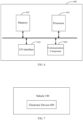
- FIG. 6 is a block diagram of an electronic device 600 according to an exemplary embodiment.
- the electronic device 600 may include: a processor 601 and a memory 602.
- the electronic device 600 may also include one or more of an input/output (I/O) interface 603, and a communication component 604.
- I/O input/output
- the processor 601 is configured to control the overall operation of the electronic device 600 to complete all or part of the steps in the above-mentioned vehicle control method.
- the memory 602 is configured to store various types of data to support operations on the electronic device 600. These data may include, for example, instructions for any application program or method operating on the electronic device 600, as well as application program-related data.
- the memory 602 may be implemented by any type of volatile or non-volatile storage device or a combination thereof, such as a static random access memory (Static Random Access Memory, SRAM for short), an electrically erasable programmable read-only memory ( Electrically Erasable Programmable Read-Only Memory (EEPROM for short), an erasable programmable read-only memory (Erasable Programmable Read-Only Memory, EPROM for short), a programmable read-only memory (Programmable Read-Only Memory, PROM for short), a read-only memory (Read-Only Memory, ROM for short), a magnetic memory, a flash memory, a magnetic disk or an optical disk.
- SRAM static random access memory
- EEPROM Electrically Erasable Programmable Read-Only Memory
- EPROM erasable Programmable Read-Only Memory
- PROM Programmable Read-Only Memory
- PROM Read-Only Memory
- the communication component 604 is configured for wired or wireless communication between the electronic device 600 and other devices.
- Wireless communication such as Wi-Fi, Bluetooth, a near field communication (Near Field Communication, NFC for short), 2G, 3G, 4G, NB-IOT, eMTC, or other 5G, etc., or a combination of one or more of them, which is not limited here. Therefore, the corresponding communication component 604 may include: Wi-Fi module, Bluetooth module, NFC module, etc.
- the electronic device 600 may be are implemented as one or more an application specific integrated circuit, (Application Specific Integrated Circuit, ASIC for short), a digital signal processor (Digital Signal Processor, DSP for short), a digital signal processing device (Digital Signal Processing Device, DSPD for short), a programmable logic device (Programmable Logic Device, PLD for short), a field programmable gate array (Field Programmable Gate Array, FPGA for short), a controller, a microcontroller, a microprocessor or other electronic components, for executing the above vehicle control method.
- ASIC Application Specific Integrated Circuit
- DSP Digital Signal Processor
- DSPD Digital Signal Processing Device
- PLD programmable logic device
- FPGA Field Programmable Gate Array
- a computer-readable storage medium including program instructions is also provided.
- the program instructions when executed by a processor, enables the steps of the vehicle control method to be implemented.
- the computer-readable storage medium may be the above-mentioned memory 602 including program instructions, and the above-mentioned program instructions may be executed by the processor 601 of the electronic device 600 to complete the above-mentioned vehicle control method.
- a computer program product including a computer program that is executable by a programmable device.
- the computer program having a code part that is configured to, when executed by the programmable device, execute the above vehicle control method.
- FIG. 7 shows a vehicle 100 provided by the present application. As shown in FIG. 7 , the vehicle 100 includes the above-mentioned electronic device 600.
Landscapes
- Engineering & Computer Science (AREA)
- Transportation (AREA)
- Mechanical Engineering (AREA)
- Chemical & Material Sciences (AREA)
- Combustion & Propulsion (AREA)
- Automation & Control Theory (AREA)
- Human Computer Interaction (AREA)
- Health & Medical Sciences (AREA)
- Biomedical Technology (AREA)
- General Health & Medical Sciences (AREA)
- Combined Controls Of Internal Combustion Engines (AREA)
- Control Of Vehicle Engines Or Engines For Specific Uses (AREA)
Abstract
Description
- This application claims the benefit of the
Chinese Patent Application No. 202111164068.X filed on September 30, 2021 - The present application relates to the field of vehicle control technology, and in particular to a vehicle control method, a storage medium and an electronic device.
- The vehicle's engine has a maximum speed limit for the engine defined at the time of hardware design, i.e., the maximum speed that the engine can withstand. If the engine continues to work above the maximum speed, a certain impact on the service life of the engine hardware will be resulted.
- In the existing technology, when an engine speed is greater than or equal to a preset speed threshold, an active fuel cutoff protection strategy will be implemented by the vehicle, that is, to limit or even cut off the fuel feeding to the engine according to the actual engine speed, so as to reduce the engine speed.
- However, in a case of a driver stepping on an accelerator pedal to a large extent, even if the engine's active fuel cutoff protection strategy is implemented by the vehicle, the engine speed may continue to rise, thus affecting the lifetime of the engine.
- One objective of embodiments of the present application is to provide a vehicle control method, a storage medium and an electronic device.
- Technical solutions provided by the present application are as follows:
In accordance with a first aspect, a vehicle control method is provided, which includes the following steps: - obtaining an engine speed of a vehicle and a maximum speed of an engine;
- determining, from a plurality of preset speed difference ranges, a target speed difference range where a difference between the engine speed and the maximum speed is fallen into when the difference between the engine speed and the maximum speed meets a preset condition;
- determining a motor torque coefficient corresponding to the target speed difference range, where different preset speed difference ranges correspond to different motor torque coefficients;
- adjusting a target output torque of a motor of the vehicle according to the motor torque coefficient corresponding to the target speed difference range, to reduce the target output torque.
- In one embodiment, the step of determining, from the plurality of preset speed difference ranges, the target speed difference range where the difference between the engine speed and the maximum speed is fallen into when the difference between the engine speed and the maximum speed meets the preset condition includes a step of:
determining, from the plurality of preset speed difference ranges, the target speed difference range where the difference between the engine speed and the maximum speed is fallen into when the difference obtained by subtracting the engine speed from the maximum speed is smaller than or equal to a first preset speed difference threshold, or the difference obtained by subtracting the maximum speed from the engine speed is greater than or equal to a second preset speed difference threshold. - In one embodiment, an interval of the preset speed difference range approaches zero as the engine speed increases when the engine speed is smaller than the maximum speed.
- In one embodiment, the motor torque coefficient decreases as the interval of the preset speed difference range approaches zero.
- In one embodiment, the motor torque coefficient corresponding to the speed difference range where the difference between the engine speed and the maximum speed is fallen into is zero when the engine speed is greater than or equal to the maximum speed.
- In one embodiment, the target output torque includes a maximum output torque of the motor, or a distributed torque of the motor.
- In one embodiment, when the difference between the engine speed and the maximum speed meets the preset condition, the method also includes a step of:
controlling the engine to enter an idle condition. - In one embodiment, when the difference between the engine speed and the maximum speed meets the preset condition, the method also includes a step of:
sending a warning message, and the warning message is used to indicate an abnormality in the engine speed. - In accordance with a second aspect, a computer-readable storage medium is provided, on which a computer program is stored. The program, when executed by a processor, enables the vehicle control method according to any one of the first aspects to be implemented.
- In accordance with a third aspect, an electronic device is provided, which includes:
- a memory having a computer program stored thereon;
- a processor, which is configured to execute the computer program in the memory to implement the vehicle control method according to any one of the first aspects.
- By adopting this technical solution, the output torque of the motor is adjusted according to the difference when the difference between the engine speed and the maximum speed meets the preset condition, thus the increase of the shaft speed of the vehicle is limited to avoid the speed of the engine being driven up, such that an actual engine speed is prevented from exceeding the maximum speed that the engine can withstand, which thus can effectively protect the engine, and is conducive to prolonging the service life of the engine, and improving the user's experience.
- Beneficial effects provided by the embodiments of the present application in the second and third aspects are the same as the beneficial effects in the above-mentioned first aspect. For details, please refer to the beneficial effects of the above-mentioned first aspect.
- In order to explain the technical solutions in the embodiments of the present application more clearly, the drawings needed to be used in the description of the embodiments or exemplary technologies will be briefly introduced below. Obviously, the drawings in the following description are merely some embodiments of the present application, for those of ordinary skill in the art, other drawings may also be obtained based on these drawings without exerting creative efforts.
-
FIG. 1 is a flow chart of a vehicle control method according to an exemplary embodiment; -
FIG. 2 is a flow chart of a vehicle control method according to yet another exemplary embodiment; -
FIG. 3 is a flow chart of a vehicle control method according to yet another exemplary embodiment; -
FIG. 4 is a block diagram of a vehicle control device according to an exemplary embodiment; -
FIG. 5 is a block diagram of a vehicle control device according to yet another exemplary embodiment; -
FIG. 6 is a block diagram of an electronic device according to an exemplary embodiment; and -
FIG. 7 is a block diagram of a vehicle according to an exemplary embodiment. - In order to make the purpose, technical solutions and advantages of the present application much clearer, the present application will be further described in detail below with reference to the drawings and embodiments. It should be understood that the specific embodiments described here are only used to explain the present application and are not intended to limit the present application.
- The terms "first" and "second" are only used for descriptive purposes and cannot be understood as indicating or implying relative importance or implicitly indicating the number of technical features. The phrase "a/the plurality of" means two or more, unless otherwise expressly and specifically limited.
- First, the application scenario of the present application is explained. The present application may be applied to a vehicle control scenario. In this scenario, the vehicle's engine is running at a high speed. The engine speed, if not restricted, is likely to exceed the maximum speed that the engine can withstand, which then will result in a certain damage to the engine hardware and affect the service life of the engine.
- In the existing technology, some approaches are applied to prevent the engine speed from exceeding the maximum speed that the engine can withstand, such as the active fuel cutoff protection strategy. In this strategy, the fuel feeding to the engine will be limited or even cut off based on the actual engine speed to reduce the engine speed.
- However, the following situation may occur in hybrid vehicles. For a vehicle equipped with P2 hybrid architecture or P2P4 hybrid architecture, during an actual driving process of the vehicle, if a higher driving torque is required by a driver, the driver will depress an accelerator pedal to a greater extent, but the transmission does not shift gears, which will cause an output torque of a motor of the vehicle to increase, and then drive the engine speed to increase. As a result, the engine speed will still exceed the maximum speed after the engine's fuel feeding is limited or even cut off.
- To solve the above problem, the present application provides a vehicle control method, where the output torque of the motor is limited based on a difference between the engine speed and the maximum speed when the difference between the engine speed and the maximum speed meets a preset condition, this ensures that the engine will not be dragged to cause the speed to exceed the maximum speed.
- The present application will be described below with reference to specific embodiments.
-
FIG. 1 shows a vehicle control method provided by an embodiment of the present application. As shown inFIG. 1 , the vehicle control method includes steps of S101 to S104. - In step S101, an engine speed of a vehicle and a maximum speed of an engine are obtained.
- Here, the engine speed may be obtained through a speed sensor, the speed sensor may be arranged at a crankshaft position of the vehicle. The maximum speed of the engine may be the maximum speed that the engine can withstand without affecting its service life, the maximum speed of the engine may be obtained through the engine itself.
- In
step S 102, a target speed difference range where a difference between the engine speed and the maximum speed is fallen into is determined from a plurality of preset speed difference ranges when the difference (i.e. the above speed difference) between the engine speed and the maximum speed meets a preset condition. - The preset condition represents a tendency of the engine speed to exceed the maximum speed. In here, in case that the difference between the engine speed and the maximum speed is a difference obtained by subtracting the engine speed from the maximum speed, then the preset condition includes that the difference obtained by subtracting the engine speed from the maximum speed is smaller than or equal to a first preset speed difference threshold. In case that the difference between the engine speed and the maximum speed is a difference obtained by subtracting the maximum speed from the engine speed, then the preset condition includes that the difference obtained by subtracting the maximum speed from the engine speed is greater than or equal to a second preset speed difference threshold.
- Taking that the difference between the engine speed and the maximum speed is the difference obtained by subtracting the engine speed from the maximum speed as an example, step
S 102 is introduced. A preset speed difference threshold may be a warning difference that indicates that the engine speed is close to the maximum speed that the engine can withstand. In case that the difference obtained by subtracting the engine speed from the maximum speed is smaller than or equal to the preset speed difference threshold, in order to prevent the engine speed from continuing to rise beyond the maximum speed that the engine can withstand, the target speed difference range where the engine's current speed is fallen into can be determined from the plurality of preset speed difference ranges, and then the steps ofS 103 to S104 are performed based on the target speed difference range. The plurality of preset speed difference ranges are used to characterize multiple stages of the engine speed. - In one possible implementation, when the engine is in a fault-free condition, the preset speed difference threshold may be 300 rpm.
- By way of example, the plurality of preset speed difference ranges may be (300 rpm, 200 rpm), (200 rpm, 100 rpm), (100 rpm, 50 rpm), (50 rpm, 0 rpm) and below 0 rpm. In case that the difference obtained by subtracting the engine speed from the maximum speed is smaller than or equal to 300 rpm and greater than 200 rpm, then it is determined that the difference obtained by subtracting the engine speed from the maximum speed is within the target speed difference range of (300 rpm, 200 rpm). In case that the difference obtained by subtracting the engine speed from the maximum speed is smaller than or equal to 200 rpm and greater than 100 rpm, then it is determined that the difference obtained by subtracting the engine speed from the maximum speed is within the target speed difference range of (200 rpm, 100 rpm). In case that the difference obtained by subtracting the engine speed from the maximum speed is smaller than or equal to 100 rpm and greater than 50 rpm, then it is determined that the difference obtained by subtracting the engine speed from the maximum speed is within the target speed difference range of (100 rpm, 50 rpm). In case that the difference obtained by subtracting the engine speed from the maximum speed is smaller than or equal to 50 rpm and greater than 0 rpm, then it is determined that the difference obtained by subtracting the engine speed from the maximum speed is within the target speed difference range of (50 rpm, 0 rpm). In case that the difference obtained by subtracting the engine speed from the maximum speed is smaller than or equal to 0 rpm, then it is determined that the engine speed is above the maximum speed.
- In another possible implementation, when the engine is in a fault condition, to prevent further serious engine faults, the preset speed difference threshold may be appropriately increased. For example, the preset speed difference threshold may be 500 rpm.
- By way of example, the plurality of preset speed difference ranges may be (500 rpm, 300 rpm), (300 rpm, 200 rpm), (200 rpm, 100 rpm), (100 rpm, 50 rpm), (50 rpm, 0 rpm) and below 0 rpm. In case that the difference obtained by subtracting the engine speed from the maximum speed is smaller than or equal to 500 rpm and greater than 300 rpm, then it is determined that the difference obtained by subtracting the engine speed from the maximum speed is within the target speed difference range of (500 rpm, 300 rpm). In case that the difference obtained by subtracting the engine speed from the maximum speed is smaller than or equal to 300 rpm and greater than 200 rpm, then it is determined that the difference obtained by subtracting the engine speed from the maximum speed is within the target speed difference range of (300 rpm, 200 rpm). In case that the difference obtained by subtracting the engine speed from the maximum speed is smaller than or equal to 200 rpm and greater than 100 rpm, then it is determined that the difference obtained by subtracting the engine speed from the maximum speed is within the target speed difference range of (200 rpm, 100 rpm). In case that the difference obtained by subtracting the engine speed from the maximum speed is smaller than or equal to 100 rpm and greater than 50 rpm, then it is determined that the difference obtained by subtracting the engine speed from the maximum speed is within the target speed difference range of (100 rpm, 50 rpm). In case that the difference obtained by subtracting the engine speed from the maximum speed is smaller than or equal to 50 rpm and greater than 0 rpm, then it is determined that the difference obtained by subtracting the engine speed from the maximum speed is within the target speed difference range of (50 rpm, 0 rpm). In case that the difference obtained by subtracting the engine speed from the maximum speed is smaller than or equal to 0 rpm, then it is determined that the engine speed is above the maximum speed.
- In case that the difference between the engine speed and the maximum speed is the difference obtained by subtracting the maximum speed from the engine speed, the corresponding descriptions are similar to the above embodiment and will not be repeated here.
- It should be noted that the above-mentioned maximum speed, preset speed difference threshold and plurality of preset speed difference ranges may be preset according to different engine types and models or experimental values. The examples here are used for illustrative purposes only and are not intended to limit the present application.
- In step S103, a motor torque coefficient corresponding to the target speed difference range is determined.
- Here, different preset speed difference ranges correspond to different motor torque coefficients. The motor torque coefficient is used to adjust the output torque of the motor. The motor torque coefficient corresponding to the engine speed may be obtained through a preset coefficient correspondence relation. The preset coefficient correspondence relation includes motor torque coefficients corresponding to different preset speed difference ranges.
- Here, when the engine speed is smaller than the maximum speed, an interval of the preset speed difference range approaches zero as the engine speed increases. The motor torque coefficient decreases as the interval of the preset speed difference range approaches zero. If the motor torque coefficient corresponding to a first preset speed difference range is zero, then the first preset speed difference range is a speed difference range where the difference between the engine speed and the maximum speed is fallen into when the engine speed is greater than or equal to the maximum speed.
- For example, taking that the difference is obtained by subtracting the engine speed from the maximum speed as an example, in a possible implementation, the engine is in the fault-free condition, and the preset coefficient correspondence relation may be shown in Table 1,
Table 1 Preset Speed Difference Range (300 rpm, 200 rpm) (200 rpm, 100 rpm) (100 rpm, 50 rpm) (50 rpm, 0 rpm) 0 rpm or below Motor Torque Coefficient 0.8 0.5 0.3 0.1 0 - In another possible implementation, the engine is in a fault condition, and the corresponding relationship between the preset coefficients can be shown in Table 2.
Table 2 Preset Speed Difference Range (500 rpm, 300 rpm) (300 rpm, 200 rpm) (200 rpm, 100 rpm) (100 rpm, 50 rpm) 0 rpm or below Motor Torque Coefficient 0.8 0.6 0.4 0.2 0 - It can be seen from the above Table 1 and/or Table 2 that, in case that the difference obtained by subtracting the engine speed from the maximum speed is smaller than or equal to the preset speed difference threshold, different preset speed difference ranges correspond to different motor torque coefficients, and the motor torque coefficient shows a gradient decreasing trend. The closer the engine speed is to the maximum speed that the engine can withstand, the smaller the motor torque coefficient is. The output torque of the motor is stopped when the engine speed is greater than or equal to the maximum speed that the engine can withstand.
- For the case where the difference is the difference obtained by subtracting the maximum speed from the engine speed, references can be made to the above embodiment, which will not be described again here.
- In step S104, a target output torque of a motor of the vehicle according to the motor torque coefficient corresponding to the target speed difference range, to reduce the target output torque.
- Here, the target output torque includes a maximum output torque of the motor, or alternatively, a distributed torque of the motor. The distributed torque of the motor represents the output torque of the motor indicated by the vehicle. For example, the distributed torque may be an output torque that the vehicle instructs the motor to externally respond according to the degree of opening of the accelerator pedal, a vehicle speed and a driving mode after the accelerator pedal is depressed by a driver, so that the vehicle can quickly respond to the driver's driving intentions.
- In a possible implementation, the product of the motor torque coefficient and the maximum output torque of the motor may be taken as the adjusted maximum output torque when the target output torque includes the maximum output torque of the motor.
- Here, in case that the difference between the engine speed and the maximum speed meets the preset condition and the engine speed is smaller than the maximum speed, the motor torque coefficient decreases in a gradient as the engine speed increases, and then the limit on the maximum output torque of the motor is gradually increased to prevent the engine speed from being driven up and continuing to rise.
- In another possible implementation, the product of the motor torque coefficient and the distributed torque of the motor may be taken as the adjusted output torque when the target output torque includes the distributed torque of the motor.
- The product of the motor torque coefficient and the distributed torque of the motor is taken as the adjusted distributed torque of the motor after the corresponding motor torque coefficient is obtained according to the engine speed, which can reduce the output torque actually required for the motor and avoid the engine speed being driven and continuing to rise.
- By means of the above method, the output torque of the motor is limited to various degrees according to the speed of the engine when the difference between the engine speed and the maximum speed meets the preset condition, and the control of the output torque of the motor is gradually increased, thus, the output torque of the motor is ultimately controlled without causing the speed of the engine to further increase, thereby ensuring that the hardware of the engine is not damaged, which is conducive to prolonging the service life of the engine and improving the user's experience.
- In another embodiment of the present application, a condition of the engine may also be controlled while limiting the output torque of the motor, as shown in
FIG. 2 . Based on the steps shown inFIG. 1 , the embodiment of the present application may also include the following step S105. - In step S105, the engine controlled to enter an idle condition.
- In this step, when the output torque of the motor is limited, to further prevent the possible increase in speed of the engine, for example, the engine is controlled to enter the idle condition in case that the active fuel cutoff protection strategy of the vehicle fails, thereby the engine will no longer receive the torque output demand sent by the vehicle, so that the speed can be controlled at a lower level.
- In this way, it can be further ensured that the engine speed is controlled within the maximum speed range that the engine can withstand, which avoids the situation where the engine speed exceeds the maximum speed that may occur under some special circumstances, and is conducive to strengthening limits on engine speed.
- Based on the steps shown in
FIG. 2 , a warning message may also be sent when the engine speed exceeds a preset speed threshold, as shown inFIG. 3 . - In step S106, a warning message is sent.
- This warning message is used to indicate an abnormality in the engine speed.
- In this way, the driver can be alerted when the difference between the engine speed and the maximum speed meets the preset condition, to prompt the driver to shift gears or reduce the degree of depression of the accelerator pedal.
-
FIG. 4 is a vehicle control device provided by an embodiment of the present application. As shown inFIG. 4 , the vehicle control device includes: anacquisition module 401, adetermination module 402, aquery module 403 and acontrol module 404 - The
acquisition module 401 is configured to obtain an engine speed of a vehicle and a maximum speed of an engine; - The
determination module 402 is configured to determine, from a plurality of preset speed difference ranges, a target speed difference range where a difference between the engine speed and the maximum speed is fallen into, when the difference between the engine speed and the maximum speed meets a preset condition. - The
query module 403 is configured to determine a motor torque coefficient corresponding to the target speed difference range, where different preset speed difference ranges correspond to different motor torque coefficients. - The
control module 404 is configured to adjust a target output torque of a motor of the vehicle according to the motor torque coefficient corresponding to the target speed difference range to reduce the target output torque, and the target output torque includes a maximum output torque of the motor, or a distributed torque of the motor. - The
query module 403 is configured to obtain the motor torque coefficient corresponding to the engine speed through a preset coefficient correspondence relationship. The preset coefficient correspondence relationship includes motor torque coefficients corresponding to different preset speed difference ranges. - In case that the engine speed is smaller than the maximum speed, the interval of the preset speed difference range approaches zero as the engine speed increases. The motor torque coefficient corresponding to the preset speed difference range decreases as the interval of the preset speed difference range approaches zero. The motor torque coefficient corresponding to a first preset speed difference range is zero, and the first preset speed difference range is the speed difference range where the difference between the engine speed and the maximum speed is fallen into when the engine speed is greater than or equal to the maximum speed.
- The
control module 404 is also configured to control the engine to enter an idle condition. - By limiting the output torque of the motor to various degrees according to the difference between the engine speed and the maximum speed when the difference between the engine speed and the maximum speed meets the preset condition, the control of the output torque of the motor is gradually increased, thus, the output torque of the motor is ultimately controlled without causing the speed of the engine to further increase. In addition, the engine is controlled to be in an idle condition which avoids the situation of engine speed exceeding the maximum speed that may occur under some special circumstances. Thereby, it is ensured that the hardware of the engine will not be damaged, which is conducive to prolonging the service life of the engine and improving the user's experience.
- In addition, on the basis of the above device, as shown in
FIG. 5 , the vehicle control device also includes awarning module 405 which is configured to send a warning message, the warning message is used to indicate an abnormality in the engine speed. - In this way, the driver can be alerted when the difference between the engine speed and the maximum speed meets the preset condition, to prompt the driver to shift gears or reduce the degree of depression of the accelerator pedal, which is beneficial to further avoid affecting the service life of the engine.
- Regarding the devices in the above embodiments, the specific manner in which each module performs operations has been described in detail in the relevant method embodiments, and will not be elaborated here.
-
FIG. 6 is a block diagram of anelectronic device 600 according to an exemplary embodiment. As shown inFIG. 6 , theelectronic device 600 may include: aprocessor 601 and a memory 602. Theelectronic device 600 may also include one or more of an input/output (I/O)interface 603, and acommunication component 604. - Here, the
processor 601 is configured to control the overall operation of theelectronic device 600 to complete all or part of the steps in the above-mentioned vehicle control method. The memory 602 is configured to store various types of data to support operations on theelectronic device 600. These data may include, for example, instructions for any application program or method operating on theelectronic device 600, as well as application program-related data. The memory 602 may be implemented by any type of volatile or non-volatile storage device or a combination thereof, such as a static random access memory (Static Random Access Memory, SRAM for short), an electrically erasable programmable read-only memory ( Electrically Erasable Programmable Read-Only Memory (EEPROM for short), an erasable programmable read-only memory (Erasable Programmable Read-Only Memory, EPROM for short), a programmable read-only memory (Programmable Read-Only Memory, PROM for short), a read-only memory (Read-Only Memory, ROM for short), a magnetic memory, a flash memory, a magnetic disk or an optical disk. Thecommunication component 604 is configured for wired or wireless communication between theelectronic device 600 and other devices. Wireless communication, such as Wi-Fi, Bluetooth, a near field communication (Near Field Communication, NFC for short), 2G, 3G, 4G, NB-IOT, eMTC, or other 5G, etc., or a combination of one or more of them, which is not limited here. Therefore, thecorresponding communication component 604 may include: Wi-Fi module, Bluetooth module, NFC module, etc. - In an exemplary embodiment, the
electronic device 600 may be are implemented as one or more an application specific integrated circuit, (Application Specific Integrated Circuit, ASIC for short), a digital signal processor (Digital Signal Processor, DSP for short), a digital signal processing device (Digital Signal Processing Device, DSPD for short), a programmable logic device (Programmable Logic Device, PLD for short), a field programmable gate array (Field Programmable Gate Array, FPGA for short), a controller, a microcontroller, a microprocessor or other electronic components, for executing the above vehicle control method. - In another exemplary embodiment, a computer-readable storage medium including program instructions is also provided. The program instructions when executed by a processor, enables the steps of the vehicle control method to be implemented. For example, the computer-readable storage medium may be the above-mentioned memory 602 including program instructions, and the above-mentioned program instructions may be executed by the
processor 601 of theelectronic device 600 to complete the above-mentioned vehicle control method. - In another exemplary embodiment, a computer program product is also provided, the computer program product including a computer program that is executable by a programmable device. The computer program having a code part that is configured to, when executed by the programmable device, execute the above vehicle control method.
-
FIG. 7 shows avehicle 100 provided by the present application. As shown inFIG. 7 , thevehicle 100 includes the above-mentionedelectronic device 600. - Preferred implementations of the present application are described in detail above in conjunction with the drawings. However, the present application is not limited to the specific details in the above-mentioned implementations. A variety of simple variations of the technical scheme of this application may be carried out within the scope of the technical concept of the present application, and these simple variations shall all be included by the protection scope of the present application.
- In addition, it should be noted that each specific technical feature described in the above-mentioned specific embodiments may be combined in any suitable way in the absence of contradiction. To avoid unnecessary duplication, the various possible combinations are not stated separately in this application.
- The above are only optional embodiments of the present application and are not intended to limit the present application. Various modifications and variations may be made to the present application by those skilled in the art. Any modifications, equivalent substitutions, improvements, etc. made within the spirit and principles of the present application shall be included within the scope of the claims of the present application.
Claims (10)
- A vehicle control method, characterized by comprising:obtaining an engine speed of a vehicle and a maximum speed of an engine;determining, from a plurality of preset speed difference ranges, a target speed difference range where a difference between the engine speed and the maximum speed is fallen into when the difference between the engine speed and the maximum speed meets a preset condition;determining a motor torque coefficient corresponding to the target speed difference range, wherein different preset speed difference ranges correspond to different motor torque coefficients; andadjusting a target output torque of a motor of the vehicle according to the motor torque coefficient corresponding to the target speed difference range to reduce the target output torque.
- The vehicle control method according to claim 1, characterized in that, said determining, from the plurality of preset speed difference ranges, the target speed difference range where the difference between the engine speed and the maximum speed is fallen into when the difference between the engine speed and the maximum speed meets the preset condition, comprises:
determining, from the plurality of preset speed difference ranges, the target speed difference range where the difference between the engine speed and the maximum speed is fallen into when the difference obtained by subtracting the engine speed from the maximum speed is smaller than or equal to a first preset speed difference threshold, or the difference obtained by subtracting the maximum speed from the engine speed is greater than or equal to a second preset speed difference threshold. - The vehicle control method according to claim 1, characterized in that an interval of the preset speed difference range approaches zero as the engine speed increases when the engine speed is smaller than the maximum speed.
- The vehicle control method according to claim 1, characterized in that the motor torque coefficient decreases as an interval of the preset speed difference range approaches zero.
- The vehicle control method according to claim 1, characterized in that the motor torque coefficient corresponding to a speed difference range where the difference between the engine speed and the maximum speed is fallen into is zero when the engine speed is greater than or equal to the maximum speed.
- The vehicle control method according to claim 1, characterized in that the target output torque comprises a maximum output torque of the motor, or a distributed torque of the motor.
- The vehicle control method according to claim 1, characterized in that, when the difference between the engine speed and the maximum speed meets the preset condition, the vehicle control method further comprises:
controlling the engine to enter an idle condition. - The vehicle control method according to any one of claims 1 to 6, characterized in that, when the difference between the engine speed and the maximum speed meets the preset condition, the vehicle control method further comprises:
sending a warning message, wherein the warning message is used to indicate an abnormality in the engine speed. - A computer-readable storage medium on which a computer program is stored, characterized in that, the program, when executed by a processor, enables steps of the method according to any one of claims 1-8 to be implemented.
- An electronic device, characterized by comprising:a memory on which a computer program is stored;a processor, configured to execute the computer program in the memory to implement steps of the method according to any one of claims 1-8.
Applications Claiming Priority (2)
| Application Number | Priority Date | Filing Date | Title |
|---|---|---|---|
| CN202111164068.XA CN114954416B (en) | 2021-09-30 | 2021-09-30 | Vehicle control method, device, storage medium, electronic equipment and vehicle |
| PCT/CN2022/122518 WO2023051676A1 (en) | 2021-09-30 | 2022-09-29 | Vehicle control method, storage medium, and electronic device |
Publications (3)
| Publication Number | Publication Date |
|---|---|
| EP4410618A1 true EP4410618A1 (en) | 2024-08-07 |
| EP4410618A4 EP4410618A4 (en) | 2025-01-22 |
| EP4410618B1 EP4410618B1 (en) | 2025-12-31 |
Family
ID=82975280
Family Applications (1)
| Application Number | Title | Priority Date | Filing Date |
|---|---|---|---|
| EP22875058.4A Active EP4410618B1 (en) | 2021-09-30 | 2022-09-29 | VEHICLE CONTROL METHOD, STORAGE MEDIUM AND ELECTRONIC DEVICE |
Country Status (3)
| Country | Link |
|---|---|
| EP (1) | EP4410618B1 (en) |
| CN (1) | CN114954416B (en) |
| WO (1) | WO2023051676A1 (en) |
Families Citing this family (5)
| Publication number | Priority date | Publication date | Assignee | Title |
|---|---|---|---|---|
| CN114954416B (en) * | 2021-09-30 | 2025-09-19 | 长城汽车股份有限公司 | Vehicle control method, device, storage medium, electronic equipment and vehicle |
| CN115355313B (en) * | 2022-08-31 | 2023-07-07 | 东风商用车有限公司 | Reverse gear vehicle speed adjusting method, device and equipment and readable storage medium |
| CN115782884B (en) * | 2022-11-28 | 2026-03-24 | 东风汽车集团股份有限公司 | Shift control methods, devices, media and vehicles |
| CN116001768A (en) * | 2022-12-30 | 2023-04-25 | 潍柴动力股份有限公司 | Control method of hybrid power system |
| CN116512931A (en) * | 2023-05-08 | 2023-08-01 | 浩智增程科技(安徽)有限公司 | Motor starting control method and device |
Family Cites Families (18)
| Publication number | Priority date | Publication date | Assignee | Title |
|---|---|---|---|---|
| US7236873B2 (en) * | 2004-07-23 | 2007-06-26 | Ford Global Technologies, Llc | System and method of controlling a hybrid electric vehicle |
| US7524265B2 (en) * | 2006-07-05 | 2009-04-28 | Gm Global Technology Operations, Inc. | Powertrain overspeed protection |
| KR20130140104A (en) * | 2011-01-21 | 2013-12-23 | 히다찌 겐끼 가부시키가이샤 | Work vehicle control apparatus and work vehicle |
| US20130006456A1 (en) * | 2011-06-29 | 2013-01-03 | Caterpillar Inc. | Systems and methods for engine load management for electric drive vehicles |
| KR101371481B1 (en) * | 2012-12-11 | 2014-03-10 | 기아자동차주식회사 | Method and system for controlling maximum speed limit of engine and motor of hybrid electrical vehicle |
| CN103248281B (en) * | 2013-04-18 | 2016-05-11 | 奇瑞新能源汽车技术有限公司 | A kind of electric automobile overspeed protection control method, system and electric automobile |
| US9932914B2 (en) * | 2015-04-14 | 2018-04-03 | Ford Global Technologies, Llc | Method for increasing electric operation in hybrid electric vehicles |
| CN107031452A (en) * | 2016-11-23 | 2017-08-11 | 北京新能源汽车股份有限公司 | Motor control method and device |
| US10814861B2 (en) * | 2017-07-24 | 2020-10-27 | Ford Global Technologies, Llc | Systems and methods for controlling engine speed in a hybrid vehicle |
| CN108058617A (en) * | 2017-12-01 | 2018-05-22 | 北京新能源汽车股份有限公司 | Motor overspeed processing method, vehicle control unit and vehicle |
| JP7183924B2 (en) * | 2019-04-05 | 2022-12-06 | トヨタ自動車株式会社 | hybrid vehicle |
| JP7226220B2 (en) * | 2019-09-20 | 2023-02-21 | トヨタ自動車株式会社 | Hybrid vehicle control device |
| JP2021049807A (en) * | 2019-09-20 | 2021-04-01 | トヨタ自動車株式会社 | Control device of hybrid vehicle |
| JP7196805B2 (en) * | 2019-09-20 | 2022-12-27 | トヨタ自動車株式会社 | Hybrid vehicle control device |
| CN112664338B (en) * | 2020-12-03 | 2023-05-12 | 浙江吉利控股集团有限公司 | Method, system and computer storage medium for eliminating engine shake |
| CN112879168B (en) * | 2021-01-26 | 2022-08-30 | 三一汽车起重机械有限公司 | Engine overspeed protection control method, control device and vehicle |
| CN113071329A (en) * | 2021-03-23 | 2021-07-06 | 北汽福田汽车股份有限公司 | Vehicle and motor rotating speed control method and device thereof and storage medium |
| CN114954416B (en) * | 2021-09-30 | 2025-09-19 | 长城汽车股份有限公司 | Vehicle control method, device, storage medium, electronic equipment and vehicle |
-
2021
- 2021-09-30 CN CN202111164068.XA patent/CN114954416B/en active Active
-
2022
- 2022-09-29 EP EP22875058.4A patent/EP4410618B1/en active Active
- 2022-09-29 WO PCT/CN2022/122518 patent/WO2023051676A1/en not_active Ceased
Also Published As
| Publication number | Publication date |
|---|---|
| CN114954416A (en) | 2022-08-30 |
| CN114954416B (en) | 2025-09-19 |
| WO2023051676A1 (en) | 2023-04-06 |
| EP4410618A4 (en) | 2025-01-22 |
| EP4410618B1 (en) | 2025-12-31 |
Similar Documents
| Publication | Publication Date | Title |
|---|---|---|
| EP4410618A1 (en) | Vehicle control method, storage medium, and electronic device | |
| EP2548779A2 (en) | Control unit for hybrid vehicle | |
| CN113586272B (en) | Engine control method and device | |
| KR102008605B1 (en) | Control method of electric oil pump | |
| EP4438367A1 (en) | Drive motor stalling cooling method and apparatus for vehicle, and vehicle | |
| RU2676892C2 (en) | Blower noise compensation method and system in a vehicle | |
| CN114810451B (en) | Vehicle control method, device, medium, equipment and vehicle | |
| US7263832B2 (en) | Method and arrangement for controlling an electrically operated charger | |
| US10495009B2 (en) | Apparatus and method for controlling operation of engine | |
| CN112092646A (en) | Vehicle control method and device, storage medium and vehicle | |
| US20230203784A1 (en) | Machine | |
| CN117662284A (en) | Troubleshooting method, device, vehicle and storage medium for electronic water pump | |
| US10697381B2 (en) | Method for operating a drive device of a motor vehicle and corresponding drive device | |
| CN113525335A (en) | Method and device for regulating engine speed, medium and vehicle | |
| KR102892115B1 (en) | Method for protecting electric motors from overload, electric motor controllers, automobiles, and storage media | |
| CN115214602B (en) | Hybrid vehicle engine shutdown control method, device, vehicle and medium | |
| JP4297835B2 (en) | Abnormality judgment device for fuel vapor purge system | |
| US9227625B2 (en) | Method for operating a driving system, in particular, of a motor vehicle | |
| US8825285B2 (en) | Method and apparatus for operating a drive device, in particular an engine cooling fan of a motor vehicle | |
| KR100520569B1 (en) | Method of controlling creep torque for fuel cell electric vehicle | |
| CN117621821B (en) | Vehicle speed limiting method and device, vehicle, storage medium and electronic equipment | |
| JP7687266B2 (en) | Fuel Supply System | |
| KR0158139B1 (en) | Idle speed compensating device and method under electric load state | |
| CN114930004A (en) | System and method for controlling the fuel supply to an engine and vehicle comprising such a system | |
| KR100422665B1 (en) | Method of controlling fuel for vehicles |
Legal Events
| Date | Code | Title | Description |
|---|---|---|---|
| STAA | Information on the status of an ep patent application or granted ep patent |
Free format text: STATUS: THE INTERNATIONAL PUBLICATION HAS BEEN MADE |
|
| PUAI | Public reference made under article 153(3) epc to a published international application that has entered the european phase |
Free format text: ORIGINAL CODE: 0009012 |
|
| STAA | Information on the status of an ep patent application or granted ep patent |
Free format text: STATUS: REQUEST FOR EXAMINATION WAS MADE |
|
| 17P | Request for examination filed |
Effective date: 20240429 |
|
| AK | Designated contracting states |
Kind code of ref document: A1 Designated state(s): AL AT BE BG CH CY CZ DE DK EE ES FI FR GB GR HR HU IE IS IT LI LT LU LV MC MK MT NL NO PL PT RO RS SE SI SK SM TR |
|
| DAV | Request for validation of the european patent (deleted) | ||
| DAX | Request for extension of the european patent (deleted) | ||
| A4 | Supplementary search report drawn up and despatched |
Effective date: 20241220 |
|
| RIC1 | Information provided on ipc code assigned before grant |
Ipc: B60W 30/188 20120101ALI20241216BHEP Ipc: B60W 20/15 20160101ALI20241216BHEP Ipc: B60W 10/08 20060101ALI20241216BHEP Ipc: B60W 10/06 20060101AFI20241216BHEP |
|
| GRAP | Despatch of communication of intention to grant a patent |
Free format text: ORIGINAL CODE: EPIDOSNIGR1 |
|
| STAA | Information on the status of an ep patent application or granted ep patent |
Free format text: STATUS: GRANT OF PATENT IS INTENDED |
|
| INTG | Intention to grant announced |
Effective date: 20250804 |
|
| GRAS | Grant fee paid |
Free format text: ORIGINAL CODE: EPIDOSNIGR3 |
|
| GRAA | (expected) grant |
Free format text: ORIGINAL CODE: 0009210 |
|
| STAA | Information on the status of an ep patent application or granted ep patent |
Free format text: STATUS: THE PATENT HAS BEEN GRANTED |
|
| AK | Designated contracting states |
Kind code of ref document: B1 Designated state(s): AL AT BE BG CH CY CZ DE DK EE ES FI FR GB GR HR HU IE IS IT LI LT LU LV MC MK MT NL NO PL PT RO RS SE SI SK SM TR |
|
| REG | Reference to a national code |
Ref country code: CH Ref legal event code: F10 Free format text: ST27 STATUS EVENT CODE: U-0-0-F10-F00 (AS PROVIDED BY THE NATIONAL OFFICE) Effective date: 20251231 Ref country code: GB Ref legal event code: FG4D |
|
| REG | Reference to a national code |
Ref country code: DE Ref legal event code: R096 Ref document number: 602022028141 Country of ref document: DE |
|
| REG | Reference to a national code |
Ref country code: IE Ref legal event code: FG4D |
|
| P01 | Opt-out of the competence of the unified patent court (upc) registered |
Free format text: CASE NUMBER: UPC_APP_0005850_4410618/2026 Effective date: 20260217 |
|
| REG | Reference to a national code |
Ref country code: LT Ref legal event code: MG9D |
|
| PG25 | Lapsed in a contracting state [announced via postgrant information from national office to epo] |
Ref country code: NO Free format text: LAPSE BECAUSE OF FAILURE TO SUBMIT A TRANSLATION OF THE DESCRIPTION OR TO PAY THE FEE WITHIN THE PRESCRIBED TIME-LIMIT Effective date: 20260331 |
|
| PG25 | Lapsed in a contracting state [announced via postgrant information from national office to epo] |
Ref country code: FI Free format text: LAPSE BECAUSE OF FAILURE TO SUBMIT A TRANSLATION OF THE DESCRIPTION OR TO PAY THE FEE WITHIN THE PRESCRIBED TIME-LIMIT Effective date: 20251231 Ref country code: HR Free format text: LAPSE BECAUSE OF FAILURE TO SUBMIT A TRANSLATION OF THE DESCRIPTION OR TO PAY THE FEE WITHIN THE PRESCRIBED TIME-LIMIT Effective date: 20251231 |
|
| PG25 | Lapsed in a contracting state [announced via postgrant information from national office to epo] |
Ref country code: RS Free format text: LAPSE BECAUSE OF FAILURE TO SUBMIT A TRANSLATION OF THE DESCRIPTION OR TO PAY THE FEE WITHIN THE PRESCRIBED TIME-LIMIT Effective date: 20260331 |
|
| PG25 | Lapsed in a contracting state [announced via postgrant information from national office to epo] |
Ref country code: LV Free format text: LAPSE BECAUSE OF FAILURE TO SUBMIT A TRANSLATION OF THE DESCRIPTION OR TO PAY THE FEE WITHIN THE PRESCRIBED TIME-LIMIT Effective date: 20251231 |