EP4410617A1 - Pneumatic brake actuator and pushrod boot for such actuator - Google Patents
Pneumatic brake actuator and pushrod boot for such actuator Download PDFInfo
- Publication number
- EP4410617A1 EP4410617A1 EP23154730.8A EP23154730A EP4410617A1 EP 4410617 A1 EP4410617 A1 EP 4410617A1 EP 23154730 A EP23154730 A EP 23154730A EP 4410617 A1 EP4410617 A1 EP 4410617A1
- Authority
- EP
- European Patent Office
- Prior art keywords
- section
- rod
- piston
- mantle
- brake actuator
- Prior art date
- Legal status (The legal status is an assumption and is not a legal conclusion. Google has not performed a legal analysis and makes no representation as to the accuracy of the status listed.)
- Granted
Links
Images


Classifications
-
- B—PERFORMING OPERATIONS; TRANSPORTING
- B60—VEHICLES IN GENERAL
- B60T—VEHICLE BRAKE CONTROL SYSTEMS OR PARTS THEREOF; BRAKE CONTROL SYSTEMS OR PARTS THEREOF, IN GENERAL; ARRANGEMENT OF BRAKING ELEMENTS ON VEHICLES IN GENERAL; PORTABLE DEVICES FOR PREVENTING UNWANTED MOVEMENT OF VEHICLES; VEHICLE MODIFICATIONS TO FACILITATE COOLING OF BRAKES
- B60T17/00—Component parts, details, or accessories of power brake systems not covered by groups B60T8/00, B60T13/00 or B60T15/00, or presenting other characteristic features
- B60T17/08—Brake cylinders other than ultimate actuators
- B60T17/083—Combination of service brake actuators with spring loaded brake actuators
-
- B—PERFORMING OPERATIONS; TRANSPORTING
- B60—VEHICLES IN GENERAL
- B60T—VEHICLE BRAKE CONTROL SYSTEMS OR PARTS THEREOF; BRAKE CONTROL SYSTEMS OR PARTS THEREOF, IN GENERAL; ARRANGEMENT OF BRAKING ELEMENTS ON VEHICLES IN GENERAL; PORTABLE DEVICES FOR PREVENTING UNWANTED MOVEMENT OF VEHICLES; VEHICLE MODIFICATIONS TO FACILITATE COOLING OF BRAKES
- B60T11/00—Transmitting braking action from initiating means to ultimate brake actuator without power assistance or drive or where such assistance or drive is irrelevant
-
- B—PERFORMING OPERATIONS; TRANSPORTING
- B60—VEHICLES IN GENERAL
- B60T—VEHICLE BRAKE CONTROL SYSTEMS OR PARTS THEREOF; BRAKE CONTROL SYSTEMS OR PARTS THEREOF, IN GENERAL; ARRANGEMENT OF BRAKING ELEMENTS ON VEHICLES IN GENERAL; PORTABLE DEVICES FOR PREVENTING UNWANTED MOVEMENT OF VEHICLES; VEHICLE MODIFICATIONS TO FACILITATE COOLING OF BRAKES
- B60T17/00—Component parts, details, or accessories of power brake systems not covered by groups B60T8/00, B60T13/00 or B60T15/00, or presenting other characteristic features
- B60T17/08—Brake cylinders other than ultimate actuators
- B60T17/081—Single service brake actuators
-
- F—MECHANICAL ENGINEERING; LIGHTING; HEATING; WEAPONS; BLASTING
- F16—ENGINEERING ELEMENTS AND UNITS; GENERAL MEASURES FOR PRODUCING AND MAINTAINING EFFECTIVE FUNCTIONING OF MACHINES OR INSTALLATIONS; THERMAL INSULATION IN GENERAL
- F16D—COUPLINGS FOR TRANSMITTING ROTATION; CLUTCHES; BRAKES
- F16D65/00—Parts or details
- F16D65/005—Components of axially engaging brakes not otherwise provided for
-
- F—MECHANICAL ENGINEERING; LIGHTING; HEATING; WEAPONS; BLASTING
- F16—ENGINEERING ELEMENTS AND UNITS; GENERAL MEASURES FOR PRODUCING AND MAINTAINING EFFECTIVE FUNCTIONING OF MACHINES OR INSTALLATIONS; THERMAL INSULATION IN GENERAL
- F16D—COUPLINGS FOR TRANSMITTING ROTATION; CLUTCHES; BRAKES
- F16D65/00—Parts or details
- F16D65/14—Actuating mechanisms for brakes; Means for initiating operation at a predetermined position
- F16D65/16—Actuating mechanisms for brakes; Means for initiating operation at a predetermined position arranged in or on the brake
- F16D65/18—Actuating mechanisms for brakes; Means for initiating operation at a predetermined position arranged in or on the brake adapted for drawing members together, e.g. for disc brakes
-
- F—MECHANICAL ENGINEERING; LIGHTING; HEATING; WEAPONS; BLASTING
- F16—ENGINEERING ELEMENTS AND UNITS; GENERAL MEASURES FOR PRODUCING AND MAINTAINING EFFECTIVE FUNCTIONING OF MACHINES OR INSTALLATIONS; THERMAL INSULATION IN GENERAL
- F16D—COUPLINGS FOR TRANSMITTING ROTATION; CLUTCHES; BRAKES
- F16D65/00—Parts or details
- F16D65/14—Actuating mechanisms for brakes; Means for initiating operation at a predetermined position
- F16D65/28—Actuating mechanisms for brakes; Means for initiating operation at a predetermined position arranged apart from the brake
-
- F—MECHANICAL ENGINEERING; LIGHTING; HEATING; WEAPONS; BLASTING
- F16—ENGINEERING ELEMENTS AND UNITS; GENERAL MEASURES FOR PRODUCING AND MAINTAINING EFFECTIVE FUNCTIONING OF MACHINES OR INSTALLATIONS; THERMAL INSULATION IN GENERAL
- F16D—COUPLINGS FOR TRANSMITTING ROTATION; CLUTCHES; BRAKES
- F16D2125/00—Components of actuators
- F16D2125/02—Fluid-pressure mechanisms
- F16D2125/06—Pistons
-
- F—MECHANICAL ENGINEERING; LIGHTING; HEATING; WEAPONS; BLASTING
- F16—ENGINEERING ELEMENTS AND UNITS; GENERAL MEASURES FOR PRODUCING AND MAINTAINING EFFECTIVE FUNCTIONING OF MACHINES OR INSTALLATIONS; THERMAL INSULATION IN GENERAL
- F16D—COUPLINGS FOR TRANSMITTING ROTATION; CLUTCHES; BRAKES
- F16D2125/00—Components of actuators
- F16D2125/02—Fluid-pressure mechanisms
- F16D2125/08—Seals, e.g. piston seals
-
- F—MECHANICAL ENGINEERING; LIGHTING; HEATING; WEAPONS; BLASTING
- F16—ENGINEERING ELEMENTS AND UNITS; GENERAL MEASURES FOR PRODUCING AND MAINTAINING EFFECTIVE FUNCTIONING OF MACHINES OR INSTALLATIONS; THERMAL INSULATION IN GENERAL
- F16D—COUPLINGS FOR TRANSMITTING ROTATION; CLUTCHES; BRAKES
- F16D2127/00—Auxiliary mechanisms
- F16D2127/02—Release mechanisms
Definitions
- the invention relates to a pneumatic brake actuator for a vehicle, in particular a commercial vehicle, comprising an actuator housing having a pressure chamber and a piston chamber, a piston that is mounted inside the piston chamber and configured to reciprocatingly move between a retained position and extended position as a function of pressure inside the pressure chamber, a piston rod connected to the piston, wherein said piston rod is guided through the actuator housing via a rod opening, a compression spring being effective to push the piston towards the retained position and a rod boot for sealing the rod opening, wherein said rod boot is connected to the rod opening and the piston rod, said rod boot comprising a mantle, said mantle having a first section and a second section opposite from the first section and wherein the first section is connected to the rod opening and the section is connected to a mounting section of the piston rod.
- Pneumatic brake actuators of the aforementioned kind are commonly used in the commercial vehicle industry. It is the aim of such pneumatic brake actuator to generate a braking force which is, in turn, transmitted to the vehicle wheel.
- pneumatic brake actuator comprise a housing which comprises a pressure chamber and a piston chamber having a piston mounted therein.
- the piston is configured to reciprocatingly move between a retained position and an extended position as a function of pressure inside the pressure chamber.
- the piston is connected to a piston rod which is guided through an out of the actuator housing via a rod opening.
- a rod boot is utilized for sealing the rod opening.
- the rod boot is connected to the rod opening and the piston rod.
- actuators are commonly used and well-proven, there is still room for improvement.
- One major drawback associated with these kinds of actuators is that the actuator housing needs to provide an accommodation volume for accommodating the rod boot, in particular when the piston is in its extended position and the rod boot is compressed. Furthermore, the compressed rod boot generates a counterforce acting towards the retained position which needs to be overcome by an additional degree of pressure inside the pressure chamber. When the pressure inside the pressure chamber is limited, the maximum stroke of the piston rod might not be available due to the above.
- the invention attains the aforementioned object by suggesting a pneumatic brake actuator according to claim 1.
- the second section of the rod boot is inverted inwardly relative to the first section, wherein a longitudinal dimension of the first section and a longitudinal dimension of the second section vary with respect to each other as a function of a relative position of the first section to the second section.
- the invention is based upon the finding that by utilizing a rod boot having one section inverted inwardly relative to the other section, the rod boot is moved with the respective section of the piston rod out of the actuator housing when the piston rod is moved into its extended position.
- the rod boot requires a considerable less installation volume within the actuator housing.
- no counterforce is generated when the piston rod is in the extended position, since the rod boot would not be compressed inside the actuator housing. For a given pressure inside the pressure chamber, this results in a better output regarding the maximum extended position, also called "maximum stroke".
- the new design allows for a reduction of the overall length of the actuator.
- the rod boot extends out of the actuator housing through the rod opening, when the piston is moved towards its retained position.
- a diameter of the mantle tappers from the first section to the second section. This ensures that the length of the first section and the second section can vary as a function of the relative position of the first section of the second section without substantial friction between the sections.
- the mantle comprises a varying thickness.
- the thickness of the mantle can be used as another means to ensure that the first section and the second section can be moved conveniently with regard to one another.
- the thickness of the mantle may be locally increased for those sections of the mantle that are heavily stressed during operation.
- the stiffness of certain sections of the mantle may be adjusted as required.
- the mantle comprises at least one rib.
- the rib is used to adjust the stiffness of the mantle. This is in particular beneficial for those embodiments at which the mantle tappers from the first section to the second section. With the help of the rips, it can be ensured that the stiffness of the mantle remains constant although the mantle surface is reduced from the first section to the second section.
- said rib extends along the longitudinal axis.
- the mantle comprises four rips, said rips being equidistantly spaced around said mantle.
- the at least one rib is arranged at the inside of said mantle.
- the mantle comprises at least one groove.
- the groove is utilized for adjusting the stiffness of the mantle.
- the groove can also be utilized to compensate for a changing surface area of the mantle from the first section to the second section.
- the groove is arranged at the outside of the mantle.
- the groove is arranged adjacent to the at least one rib. Forming a rib at the inside of the mantle may lead to the formation of a groove at the outside.
- the first section comprises a flange section for securing said first section to the rod opening.
- the flange section is used to ensure a proper sealing of the piston chamber against the surroundings of the housing.
- the flange section comprises a circumferential groove, which is configured to form a seal with the rod opening. With the help of said groove, the rod boot can be easily installed at the housing while it is at the same time ensured that the boot forms a durable connection with the housing.
- the second section comprises a shoulder for engaging with a corresponding shoulder of the piston rod to form a seal therewith.
- the second section is secured to said piston rod by means of a clamping ring.
- a clamping ring With the help of said clamping ring, the durability of the connection between rod boot and piston rod is improved.
- the invention as herein above has been described according to a first aspect relating to the inventive brake actuator.
- the invention however also relates to a rod boot for sealing a rod opening for a pneumatic brake actuator of a commercial vehicle, wherein said rod boot is configured to be connected to a rod opening and a piston rod, said rod boot comprising a mantle, said mantle having a first section and a second section opposite from the first section, and wherein the first section is connected to a rod opening of a pneumatic brake actuator and the second section is connected to a mounting section of a piston rod of the actuator.
- the invention suggests that the second section is inverted inwardly relative to the first section, wherein a longitudinal dimension of the first section and a longitudinal dimension of the second section vary with respect to each other as a function of a relative position of the first section to the second section.
- inventive rod boot accordingly shares the technical advantages and preferred embodiments of the inventive brake actuator.
- the invention relates to the use of a rod boot according to the previous embodiments for sealing a rod opening of a pneumatic brake actuator of a commercial vehicle.
- the inventive use of a rod boot accordingly shares the technical advantages and preferred embodiments of the inventive brake actuator and the inventive rod boot.
- Fig. 1 shows a vehicle braking system 2.
- the vehicle braking system 2 comprises a pneumatic actuator 4.
- the pneumatic actuator 4 comprises an actuator housing 6.
- the actuator housing 6 comprises a pressure chamber 8 and a piston chamber 10.
- a piston 12 is mounted in the piston chamber 10.
- the piston 12 is configured to reciprocatingly move between a retrained position 14 and in extended position 16 (shown in Fig. 2 ) as a function of pressure inside the pressure chamber 8.
- a piston rod 18 is connected to piston 12.
- the piston rod 18 is guided through and out of the actuator housing 6 via a rod opening 20.
- the pneumatic brake actuator 4 moreover comprises a compression spring 22.
- the compression spring 22 is effective to push the piston 12 towards the retained position 14.
- the pneumatic brake actuator 4 moreover comprises a rod boot 24.
- the rod boot 24 is configured for sealing the rod opening 20.
- the rod boot 24 is connected to the rod opening 20 and the piston rod 18.
- the rod boot 24 comprises a mantle 30.
- Said mantle 30 has a first section 34 and a second section 36.
- the second section 36 is opposite from the first section 34.
- the first section 36 is connected to the rod opening 20.
- the second section 36 is connected to a mounting section 38 of the piston rod 18.
- the second section 36 of the rod boot 24 is inverted inwardly 14 relative to the first section 34.
- a longitudinal dimension l 1 of the first section 34 and a longitudinal dimension l 2 of the second section 36 vary with respect to each other as a function of a relative position of the first section 34 to the second section 36.
- the braking system 2 moreover comprises a caliper box 26. In the caliper box 26 a lever 28 is arranged.
- Fig. 2 shows the actuator of Fig. 1 in an extended position 16. It can be seen, that the rod boot 24 now extends out of the actuator housing 6 through the rod opening 20 at into the caliper box 26. The volume that is now occupied by the rod boot 24 inside the actuator housing 6 is minimal.
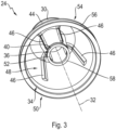
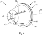
- Figs. 3 and 4 show perspective views of the rod boot 24 in perspective views.
- the rod boot comprises the mantle 30.
- the diameter 42 of the mantle 30 tapers from the first section 34 to the second section 36.
- the mantle 30 comprises a varying thickness.
- the mantle comprises four ribs 46. Said ribs 46 extend along a longitudinal axis 32.
- the ribs 46 are equidistantly spaced around the mantle 30.
- the ribs 46 are arranged at the inside 48 of the mantle 30.
- the mantle comprises groves 52.
- the groves 52 are arranged at the outside 50 of the mantle 30.
- the groves 52 are arranged adjacent to the ribs 46.
- the mantle 30 comprises four groves 52.
- a rib 46 at the inside 48 of the mantle 30 forms a grove 52 at the outside 50 of the mantle 30.
- the mantle 30 has a thickness 44.
- the first section 34 comprises a flange section 54.
- the flange section 54 is configured for securing said first section 34 to the rod opening 20.
- the flange section 54 comprises a circumferential groove 56.
- the circumferential groove 56 is configured to form a seal with the rod opening 20.
- the second section 36 comprises a shoulder 58.
- the shoulder 58 is configured for engaging with a corresponding shoulder 60 (see Figs. 1 and 2 ) of the piston rod 18, to form a seal therewith.
Landscapes
- Engineering & Computer Science (AREA)
- General Engineering & Computer Science (AREA)
- Mechanical Engineering (AREA)
- Transportation (AREA)
- Braking Arrangements (AREA)
Abstract
Description
- The invention relates to a pneumatic brake actuator for a vehicle, in particular a commercial vehicle, comprising an actuator housing having a pressure chamber and a piston chamber, a piston that is mounted inside the piston chamber and configured to reciprocatingly move between a retained position and extended position as a function of pressure inside the pressure chamber, a piston rod connected to the piston, wherein said piston rod is guided through the actuator housing via a rod opening, a compression spring being effective to push the piston towards the retained position and a rod boot for sealing the rod opening, wherein said rod boot is connected to the rod opening and the piston rod, said rod boot comprising a mantle, said mantle having a first section and a second section opposite from the first section and wherein the first section is connected to the rod opening and the section is connected to a mounting section of the piston rod.
- Pneumatic brake actuators of the aforementioned kind are commonly used in the commercial vehicle industry. It is the aim of such pneumatic brake actuator to generate a braking force which is, in turn, transmitted to the vehicle wheel.
- State of the art pneumatic brake actuator comprise a housing which comprises a pressure chamber and a piston chamber having a piston mounted therein. The piston is configured to reciprocatingly move between a retained position and an extended position as a function of pressure inside the pressure chamber. The piston is connected to a piston rod which is guided through an out of the actuator housing via a rod opening.
- To ensure that the interior of the brake caliper remains free from contamination, for example dirt or water, a rod boot is utilized for sealing the rod opening. The rod boot is connected to the rod opening and the piston rod.
- Although such actuators are commonly used and well-proven, there is still room for improvement. One major drawback associated with these kinds of actuators is that the actuator housing needs to provide an accommodation volume for accommodating the rod boot, in particular when the piston is in its extended position and the rod boot is compressed. Furthermore, the compressed rod boot generates a counterforce acting towards the retained position which needs to be overcome by an additional degree of pressure inside the pressure chamber. When the pressure inside the pressure chamber is limited, the maximum stroke of the piston rod might not be available due to the above.
- As a consequence, it was an object of the invention to provide a pneumatic brake actuator of the initially mentioned type which overcomes the aforementioned problems as much as possible. In particular, it was an object of the invention to provide a pneumatic brake actuator which comprises a smaller total length and requires less actuation pressure to operate the piston rod into its maximum stroke position.
- The invention attains the aforementioned object by suggesting a pneumatic brake actuator according to claim 1. According to the invention, it is proposed that the second section of the rod boot is inverted inwardly relative to the first section, wherein a longitudinal dimension of the first section and a longitudinal dimension of the second section vary with respect to each other as a function of a relative position of the first section to the second section.
- The invention is based upon the finding that by utilizing a rod boot having one section inverted inwardly relative to the other section, the rod boot is moved with the respective section of the piston rod out of the actuator housing when the piston rod is moved into its extended position. Thus, the rod boot requires a considerable less installation volume within the actuator housing. Furthermore, due to the rod boot design, no counterforce is generated when the piston rod is in the extended position, since the rod boot would not be compressed inside the actuator housing. For a given pressure inside the pressure chamber, this results in a better output regarding the maximum extended position, also called "maximum stroke". Furthermore, the new design allows for a reduction of the overall length of the actuator.
- According to a preferred embodiment, the rod boot extends out of the actuator housing through the rod opening, when the piston is moved towards its retained position.
- According to a preferred embodiment, a diameter of the mantle tappers from the first section to the second section. This ensures that the length of the first section and the second section can vary as a function of the relative position of the first section of the second section without substantial friction between the sections.
- Preferably, the mantle comprises a varying thickness. The thickness of the mantle can be used as another means to ensure that the first section and the second section can be moved conveniently with regard to one another. Moreover, the thickness of the mantle may be locally increased for those sections of the mantle that are heavily stressed during operation. Furthermore, the stiffness of certain sections of the mantle may be adjusted as required.
- According to yet another preferred embodiment, the mantle comprises at least one rib. The rib is used to adjust the stiffness of the mantle. This is in particular beneficial for those embodiments at which the mantle tappers from the first section to the second section. With the help of the rips, it can be ensured that the stiffness of the mantle remains constant although the mantle surface is reduced from the first section to the second section.
- Preferably, said rib extends along the longitudinal axis. According to another preferred embodiment, the mantle comprises four rips, said rips being equidistantly spaced around said mantle. Preferably, the at least one rib is arranged at the inside of said mantle.
- According to another preferred embodiment, the mantle comprises at least one groove. The groove is utilized for adjusting the stiffness of the mantle. Like the rips, the groove can also be utilized to compensate for a changing surface area of the mantle from the first section to the second section. Preferably, the groove is arranged at the outside of the mantle. According to yet another preferred embodiment, the groove is arranged adjacent to the at least one rib. Forming a rib at the inside of the mantle may lead to the formation of a groove at the outside.
- According to yet another preferred embodiment, the first section comprises a flange section for securing said first section to the rod opening. The flange section is used to ensure a proper sealing of the piston chamber against the surroundings of the housing. According to a preferred embodiment, the flange section comprises a circumferential groove, which is configured to form a seal with the rod opening. With the help of said groove, the rod boot can be easily installed at the housing while it is at the same time ensured that the boot forms a durable connection with the housing.
- According to yet another preferred embodiment, the second section comprises a shoulder for engaging with a corresponding shoulder of the piston rod to form a seal therewith. This design ensures a durable connection between the rod boot and the piston root to seal the piston chamber of the actuator.
- Preferably, the second section is secured to said piston rod by means of a clamping ring. With the help of said clamping ring, the durability of the connection between rod boot and piston rod is improved.
- The invention as herein above has been described according to a first aspect relating to the inventive brake actuator. According to a second aspect, the invention however also relates to a rod boot for sealing a rod opening for a pneumatic brake actuator of a commercial vehicle, wherein said rod boot is configured to be connected to a rod opening and a piston rod, said rod boot comprising a mantle, said mantle having a first section and a second section opposite from the first section, and wherein the first section is connected to a rod opening of a pneumatic brake actuator and the second section is connected to a mounting section of a piston rod of the actuator.
- The invention suggests that the second section is inverted inwardly relative to the first section, wherein a longitudinal dimension of the first section and a longitudinal dimension of the second section vary with respect to each other as a function of a relative position of the first section to the second section.
- The inventive rod boot accordingly shares the technical advantages and preferred embodiments of the inventive brake actuator. In this regards, reference is made to the description above and the preferred embodiments described therein.
- According to a third aspect, the invention relates to the use of a rod boot according to the previous embodiments for sealing a rod opening of a pneumatic brake actuator of a commercial vehicle. The inventive use of a rod boot accordingly shares the technical advantages and preferred embodiments of the inventive brake actuator and the inventive rod boot. In this regard, reference is made to the description above and preferred embodiments described therein.
- For a more complete understanding of the invention, the invention will now be described in detail with reference of the accompanying drawings. The detailed description will illustrate and describe what is considered as a preferred embodiment of the invention. It should of course be understood that various modifications and changes in form or detail could readily be made without departing from the spirit of the invention. It is therefore intended that the invention may not be limited to the exact form and detail shown and described herein, nor to anything or less than the whole of the invention disclosed herein and is claimed thereafter. Further, the features described in the description, the drawings and the claims disclosing the invention may be essential for the invention considered alone or in combination. In particular, any reference signs in the claims shall not be construed as limiting the scope of the invention. The wording "comprising" does not exclude other elements or steps. The word "a" or "an" does not exclude a plurality.
- The invention will now be described with reference to the accompanying drawings which illustrate, by way of example and not by way of limitations, one of several possible embodiments of the spring brake actuator proposed herein, and wherein:
- Fig. 1
- shows a preferred embodiment of pneumatic brake actuator according to the concept of the invention in a sectional view, wherein the piston is in a retained position;
- Fig. 2
- shows the preferred embodiment of the pneumatic brake actuator according to
Fig. 1 , wherein the piston is in an extended position; - Figs. 3, 4
- show perspective views of a rod boot according to the concept of the invention.
-
Fig. 1 shows avehicle braking system 2. Thevehicle braking system 2 comprises apneumatic actuator 4. Thepneumatic actuator 4 comprises anactuator housing 6. Theactuator housing 6 comprises apressure chamber 8 and apiston chamber 10. In thepiston chamber 10, apiston 12 is mounted. Thepiston 12 is configured to reciprocatingly move between a retrainedposition 14 and in extended position 16 (shown inFig. 2 ) as a function of pressure inside thepressure chamber 8. - A
piston rod 18 is connected topiston 12. Thepiston rod 18 is guided through and out of theactuator housing 6 via arod opening 20. Thepneumatic brake actuator 4 moreover comprises acompression spring 22. Thecompression spring 22 is effective to push thepiston 12 towards the retainedposition 14. Thepneumatic brake actuator 4 moreover comprises arod boot 24. Therod boot 24 is configured for sealing therod opening 20. Therod boot 24 is connected to therod opening 20 and thepiston rod 18. - The
rod boot 24 comprises amantle 30. Saidmantle 30 has afirst section 34 and asecond section 36. Thesecond section 36 is opposite from thefirst section 34. Thefirst section 36 is connected to therod opening 20. Thesecond section 36 is connected to a mountingsection 38 of thepiston rod 18. Thesecond section 36 of therod boot 24 is inverted inwardly 14 relative to thefirst section 34. A longitudinal dimension l1 of thefirst section 34 and a longitudinal dimension l2 of thesecond section 36 vary with respect to each other as a function of a relative position of thefirst section 34 to thesecond section 36. Thebraking system 2 moreover comprises acaliper box 26. In the caliper box 26 alever 28 is arranged. -
Fig. 2 shows the actuator ofFig. 1 in anextended position 16. It can be seen, that therod boot 24 now extends out of theactuator housing 6 through therod opening 20 at into thecaliper box 26. The volume that is now occupied by therod boot 24 inside theactuator housing 6 is minimal. -
Figs. 3 and4 show perspective views of therod boot 24 in perspective views. The rod boot comprises themantle 30. Thediameter 42 of themantle 30 tapers from thefirst section 34 to thesecond section 36. Furthermore, themantle 30 comprises a varying thickness. The mantle comprises fourribs 46. Saidribs 46 extend along alongitudinal axis 32. Theribs 46 are equidistantly spaced around themantle 30. Theribs 46 are arranged at the inside 48 of themantle 30. Furthermore, the mantle comprisesgroves 52. Thegroves 52 are arranged at the outside 50 of themantle 30. Thegroves 52 are arranged adjacent to theribs 46. Themantle 30 comprises fourgroves 52. Arib 46 at the inside 48 of themantle 30 forms agrove 52 at the outside 50 of themantle 30. Themantle 30 has athickness 44. - Furthermore, the
first section 34 comprises aflange section 54. Theflange section 54 is configured for securing saidfirst section 34 to therod opening 20. Theflange section 54 comprises acircumferential groove 56. Thecircumferential groove 56 is configured to form a seal with therod opening 20. Thesecond section 36 comprises ashoulder 58. Theshoulder 58 is configured for engaging with a corresponding shoulder 60 (seeFigs. 1 and2 ) of thepiston rod 18, to form a seal therewith. -
- 2
- braking system
- 4
- pneumatic brake actuator
- 6
- actuator housing
- 8
- pressure chamber
- 10
- piston chamber
- 12
- piston
- 14
- retained position
- 16
- extended position
- 18
- piston rod
- 20
- rod opening
- 22
- compression spring
- 24
- rod boot
- 26
- caliper box
- 28
- lever
- 30
- mantle
- 32
- longitudinal axis
- 34
- first section
- 36
- second section
- 38
- mounting section
- 40
- inward inversion
- 42
- mantle diameter
- 44
- mantle thickness
- 46
- rib
- 48
- mantle inside
- 50
- mantle outside
- 52
- mantle groove
- 54
- flange section
- 56
- circumferential groove
- 58
- mantle shoulder
- 60
- rod shoulder
Claims (15)
- A pneumatic brake actuator (4) for a vehicle, in particular a commercial vehicle, comprising:- an actuator housing (6) having a pressure chamber (8) and a piston chamber (10),- a piston (12) that is mounted inside the piston chamber (10) and configured to reciprocatingly move between a retained position (14) and an extended position (16) as a function of pressure inside the pressure chamber (8),- a piston rod (18) connected to the piston (12), wherein said piston rod (18) is guided through the actuator housing (6) via a rod opening (20),- a compression spring (22) being effective to push the piston (12) towards the retained position (14), and- a rod boot (24) for sealing the rod opening (20), wherein said rod boot (24) is connected to the rod opening (20) and the piston rod (18),said rod boot (24) comprising a mantle (30), said mantle (30) having a first section (34) and a second section (36) opposite from the first section (34), and wherein the first section (34) is connected to the rod opening (20) and the second section (36) is connected to a mounting section (38) of the piston rod (18),
characterized in that the second section (36) is inverted inwardly (40) relative to the first section (34), wherein a longitudinal dimension (l1) of the first section (34) and a longitudinal dimension (l2) of the second section (36) vary with respect to each other as a function of a relative position of the first section (34) to the second section (36). - The brake actuator (4) according to claim 1,
wherein the rod boot (24) extends out of the actuator housing (6) through the rod opening (20), when the piston (12) is moved towards its retained position (14). - The brake actuator (4) according to claim 1 or 2,
wherein a diameter (42) of the mantle (30) tapers from the first section (34) to the second section (36). - The brake actuator (4) according to claim 1 or 2,
wherein the mantle (30) comprises a varying thickness. - The brake actuator (4) according to any of the preceding claims,
wherein the mantle (30) comprises at least one rib (46). - The brake actuator (4) according to claim 5,
wherein said rib (46) extends along the longitudinal axis (32). - The brake actuator (4) according to claims 5 or 6,
wherein the mantle (30) comprises four ribs (46), said ribs (46) being equidistantly spaced around said mantle (30). - The brake actuator (4) according to claims 5-7,
wherein said at least one rib (46) is arranged at the inside (48) of said mantle (30). - The brake actuator (4) according to any of the preceding claims,
wherein the mantle (30) comprises at least one groove (52). - The brake actuator (4) according to claim 9,
wherein said grove (52) is arranged at the outside (50) of said mantle (30) adjacent to the at least one rib (46). - The brake actuator (4) according to any of the preceding claims,
wherein said first section (34) comprises a flange section (54) for securing said first section (34) to the rod opening (20). - The brake actuator (4) according to claim 11,
wherein said flange section (54) comprises a circumferential groove (56) configured to form a seal with the rod opening (20). - The brake actuator (4) according to any of the preceding claims,
wherein said second section (36) comprises a shoulder (58) for engaging with a corresponding shoulder (60) of the piston rod (18) to form a seal therewith. - A rod boot (24) for sealing a rod opening (20) for a pneumatic brake actuator of a commercial vehicle, wherein said rod boot (24) is configured to be connected to a rod opening (20) and a piston rod (18),
said rod boot (24) comprising a mantle (30), said mantle (30) having a first section (34) and a second section (36) opposite from the first section (34), and wherein the first section (36) is connected to a rod opening (20) of a pneumatic brake actuator (4) and the second section (36) is connected to a mounting section (38) of a piston rod (18) of the actuator (4),
characterized in that the second section (36) is inverted inwardly (40) relative to the first section (34), wherein a longitudinal dimension (l1) of the first section (34) and a longitudinal dimension (l2) of the second section (36) vary with respect to each other as a function of a relative position of the first section (34) to the second section (36). - Use of a rod boot (24) according to claim 14 for sealing a rod opening (20) of a pneumatic brake actuator (4) of a commercial vehicle.
Priority Applications (2)
| Application Number | Priority Date | Filing Date | Title |
|---|---|---|---|
| EP23154730.8A EP4410617B1 (en) | 2023-02-02 | 2023-02-02 | Pneumatic brake actuator and pushrod boot for such actuator |
| US18/428,297 US20240262325A1 (en) | 2023-02-02 | 2024-01-31 | Pneumatic brake actuator and pushrod boot for such actuator |
Applications Claiming Priority (1)
| Application Number | Priority Date | Filing Date | Title |
|---|---|---|---|
| EP23154730.8A EP4410617B1 (en) | 2023-02-02 | 2023-02-02 | Pneumatic brake actuator and pushrod boot for such actuator |
Publications (2)
| Publication Number | Publication Date |
|---|---|
| EP4410617A1 true EP4410617A1 (en) | 2024-08-07 |
| EP4410617B1 EP4410617B1 (en) | 2025-03-12 |
Family
ID=85172634
Family Applications (1)
| Application Number | Title | Priority Date | Filing Date |
|---|---|---|---|
| EP23154730.8A Active EP4410617B1 (en) | 2023-02-02 | 2023-02-02 | Pneumatic brake actuator and pushrod boot for such actuator |
Country Status (2)
| Country | Link |
|---|---|
| US (1) | US20240262325A1 (en) |
| EP (1) | EP4410617B1 (en) |
Citations (3)
| Publication number | Priority date | Publication date | Assignee | Title |
|---|---|---|---|---|
| EP0692651A1 (en) * | 1994-07-13 | 1996-01-17 | KNORR-BREMSE SYSTEME FÜR NUTZFAHRZEUGE GmbH | Disc brake cylinder, especially for utility vehicles |
| EP1791742B1 (en) * | 2004-09-06 | 2008-01-23 | KNORR-BREMSE SYSTEME FÜR NUTZFAHRZEUGE GmbH | Combined service brake and spring brake cylinder |
| US20140096678A1 (en) * | 2011-04-14 | 2014-04-10 | Nabtesco Automotive Corporation | Brake chamber, boot member, and bush member |
-
2023
- 2023-02-02 EP EP23154730.8A patent/EP4410617B1/en active Active
-
2024
- 2024-01-31 US US18/428,297 patent/US20240262325A1/en active Pending
Patent Citations (3)
| Publication number | Priority date | Publication date | Assignee | Title |
|---|---|---|---|---|
| EP0692651A1 (en) * | 1994-07-13 | 1996-01-17 | KNORR-BREMSE SYSTEME FÜR NUTZFAHRZEUGE GmbH | Disc brake cylinder, especially for utility vehicles |
| EP1791742B1 (en) * | 2004-09-06 | 2008-01-23 | KNORR-BREMSE SYSTEME FÜR NUTZFAHRZEUGE GmbH | Combined service brake and spring brake cylinder |
| US20140096678A1 (en) * | 2011-04-14 | 2014-04-10 | Nabtesco Automotive Corporation | Brake chamber, boot member, and bush member |
Also Published As
| Publication number | Publication date |
|---|---|
| EP4410617B1 (en) | 2025-03-12 |
| US20240262325A1 (en) | 2024-08-08 |
Similar Documents
| Publication | Publication Date | Title |
|---|---|---|
| KR100316215B1 (en) | Fluid Actuator with Spring Chamber Blocked | |
| EP2177411B1 (en) | Slip seal diaphragm for spring brake actuator | |
| US20210199168A1 (en) | Disc brake | |
| JP5605954B2 (en) | Smooth bore dynamic center seal for spring brake actuator | |
| CN105980225B (en) | Spring-loaded brake cylinder with emergency release device | |
| CN113795414B (en) | Hydraulic units for hydraulic vehicle brake systems | |
| JP4612993B2 (en) | Master cylinder for an electrohydraulic braking system with improved pedal feel simulation means and electrohydraulic braking system with such a master cylinder | |
| RU2126336C1 (en) | Hydraulic master cylinder | |
| RU2266220C2 (en) | Socket of counteracting plate and pneumatic booster for brake system with such socket | |
| EP4410617B1 (en) | Pneumatic brake actuator and pushrod boot for such actuator | |
| US6012378A (en) | Air brake actuator having increased output | |
| JP7507565B2 (en) | Stroke Simulator | |
| CN103958922B (en) | e.g. spring accumulator brake cylinders for motor vehicle braking | |
| US3336842A (en) | Hydraulic actuator | |
| US20170001618A1 (en) | Center bearing of adapter plate comprising rubber and rigid plastic members developed for spring brake actuators | |
| US5640893A (en) | Spring brake actuator with guide and bearing for an actuator rod | |
| JPH07293611A (en) | Collet type slack adjusting device and brake actuator | |
| EP4282722B1 (en) | Piston boot for a brake actuator, brake actuator comprising a respective piston boot and a disc brake | |
| WO1994021892A1 (en) | Sealed bearing for fluid-operated brake actuator | |
| US8360215B2 (en) | Two-stage slave cylinder | |
| US5180149A (en) | Brake cylinder piston spring | |
| US6899017B2 (en) | Wheel cylinder for actuating a vehicle brake and a method of manufacturing same | |
| KR102341550B1 (en) | Brake Acutuator | |
| EP3083353B1 (en) | Brake cylinder | |
| GB2268230A (en) | Spring brake actuator |
Legal Events
| Date | Code | Title | Description |
|---|---|---|---|
| PUAI | Public reference made under article 153(3) epc to a published international application that has entered the european phase |
Free format text: ORIGINAL CODE: 0009012 |
|
| STAA | Information on the status of an ep patent application or granted ep patent |
Free format text: STATUS: THE APPLICATION HAS BEEN PUBLISHED |
|
| AK | Designated contracting states |
Kind code of ref document: A1 Designated state(s): AL AT BE BG CH CY CZ DE DK EE ES FI FR GB GR HR HU IE IS IT LI LT LU LV MC ME MK MT NL NO PL PT RO RS SE SI SK SM TR |
|
| STAA | Information on the status of an ep patent application or granted ep patent |
Free format text: STATUS: REQUEST FOR EXAMINATION WAS MADE |
|
| 17P | Request for examination filed |
Effective date: 20240812 |
|
| RBV | Designated contracting states (corrected) |
Designated state(s): AL AT BE BG CH CY CZ DE DK EE ES FI FR GB GR HR HU IE IS IT LI LT LU LV MC ME MK MT NL NO PL PT RO RS SE SI SK SM TR |
|
| GRAP | Despatch of communication of intention to grant a patent |
Free format text: ORIGINAL CODE: EPIDOSNIGR1 |
|
| STAA | Information on the status of an ep patent application or granted ep patent |
Free format text: STATUS: GRANT OF PATENT IS INTENDED |
|
| INTG | Intention to grant announced |
Effective date: 20241219 |
|
| GRAS | Grant fee paid |
Free format text: ORIGINAL CODE: EPIDOSNIGR3 |
|
| GRAA | (expected) grant |
Free format text: ORIGINAL CODE: 0009210 |
|
| STAA | Information on the status of an ep patent application or granted ep patent |
Free format text: STATUS: THE PATENT HAS BEEN GRANTED |
|
| AK | Designated contracting states |
Kind code of ref document: B1 Designated state(s): AL AT BE BG CH CY CZ DE DK EE ES FI FR GB GR HR HU IE IS IT LI LT LU LV MC ME MK MT NL NO PL PT RO RS SE SI SK SM TR |
|
| REG | Reference to a national code |
Ref country code: GB Ref legal event code: FG4D |
|
| REG | Reference to a national code |
Ref country code: CH Ref legal event code: EP |
|
| REG | Reference to a national code |
Ref country code: DE Ref legal event code: R096 Ref document number: 602023002335 Country of ref document: DE |
|
| REG | Reference to a national code |
Ref country code: IE Ref legal event code: FG4D |
|
| PG25 | Lapsed in a contracting state [announced via postgrant information from national office to epo] |
Ref country code: RS Free format text: LAPSE BECAUSE OF FAILURE TO SUBMIT A TRANSLATION OF THE DESCRIPTION OR TO PAY THE FEE WITHIN THE PRESCRIBED TIME-LIMIT Effective date: 20250612 |
|
| PG25 | Lapsed in a contracting state [announced via postgrant information from national office to epo] |
Ref country code: FI Free format text: LAPSE BECAUSE OF FAILURE TO SUBMIT A TRANSLATION OF THE DESCRIPTION OR TO PAY THE FEE WITHIN THE PRESCRIBED TIME-LIMIT Effective date: 20250312 |
|
| PG25 | Lapsed in a contracting state [announced via postgrant information from national office to epo] |
Ref country code: ES Free format text: LAPSE BECAUSE OF FAILURE TO SUBMIT A TRANSLATION OF THE DESCRIPTION OR TO PAY THE FEE WITHIN THE PRESCRIBED TIME-LIMIT Effective date: 20250312 |
|
| REG | Reference to a national code |
Ref country code: LT Ref legal event code: MG9D |
|
| PG25 | Lapsed in a contracting state [announced via postgrant information from national office to epo] |
Ref country code: NO Free format text: LAPSE BECAUSE OF FAILURE TO SUBMIT A TRANSLATION OF THE DESCRIPTION OR TO PAY THE FEE WITHIN THE PRESCRIBED TIME-LIMIT Effective date: 20250612 |
|
| PG25 | Lapsed in a contracting state [announced via postgrant information from national office to epo] |
Ref country code: HR Free format text: LAPSE BECAUSE OF FAILURE TO SUBMIT A TRANSLATION OF THE DESCRIPTION OR TO PAY THE FEE WITHIN THE PRESCRIBED TIME-LIMIT Effective date: 20250312 |
|
| REG | Reference to a national code |
Ref country code: NL Ref legal event code: MP Effective date: 20250312 |
|
| PG25 | Lapsed in a contracting state [announced via postgrant information from national office to epo] |
Ref country code: LV Free format text: LAPSE BECAUSE OF FAILURE TO SUBMIT A TRANSLATION OF THE DESCRIPTION OR TO PAY THE FEE WITHIN THE PRESCRIBED TIME-LIMIT Effective date: 20250312 |
|
| PG25 | Lapsed in a contracting state [announced via postgrant information from national office to epo] |
Ref country code: GR Free format text: LAPSE BECAUSE OF FAILURE TO SUBMIT A TRANSLATION OF THE DESCRIPTION OR TO PAY THE FEE WITHIN THE PRESCRIBED TIME-LIMIT Effective date: 20250613 Ref country code: BG Free format text: LAPSE BECAUSE OF FAILURE TO SUBMIT A TRANSLATION OF THE DESCRIPTION OR TO PAY THE FEE WITHIN THE PRESCRIBED TIME-LIMIT Effective date: 20250312 |
|
| PG25 | Lapsed in a contracting state [announced via postgrant information from national office to epo] |
Ref country code: NL Free format text: LAPSE BECAUSE OF FAILURE TO SUBMIT A TRANSLATION OF THE DESCRIPTION OR TO PAY THE FEE WITHIN THE PRESCRIBED TIME-LIMIT Effective date: 20250312 |
|
| PG25 | Lapsed in a contracting state [announced via postgrant information from national office to epo] |
Ref country code: SE Free format text: LAPSE BECAUSE OF FAILURE TO SUBMIT A TRANSLATION OF THE DESCRIPTION OR TO PAY THE FEE WITHIN THE PRESCRIBED TIME-LIMIT Effective date: 20250312 |
|
| PG25 | Lapsed in a contracting state [announced via postgrant information from national office to epo] |
Ref country code: SM Free format text: LAPSE BECAUSE OF FAILURE TO SUBMIT A TRANSLATION OF THE DESCRIPTION OR TO PAY THE FEE WITHIN THE PRESCRIBED TIME-LIMIT Effective date: 20250312 |
|
| PG25 | Lapsed in a contracting state [announced via postgrant information from national office to epo] |
Ref country code: PT Free format text: LAPSE BECAUSE OF FAILURE TO SUBMIT A TRANSLATION OF THE DESCRIPTION OR TO PAY THE FEE WITHIN THE PRESCRIBED TIME-LIMIT Effective date: 20250714 |
|
| PG25 | Lapsed in a contracting state [announced via postgrant information from national office to epo] |
Ref country code: IT Free format text: LAPSE BECAUSE OF FAILURE TO SUBMIT A TRANSLATION OF THE DESCRIPTION OR TO PAY THE FEE WITHIN THE PRESCRIBED TIME-LIMIT Effective date: 20250312 Ref country code: PL Free format text: LAPSE BECAUSE OF FAILURE TO SUBMIT A TRANSLATION OF THE DESCRIPTION OR TO PAY THE FEE WITHIN THE PRESCRIBED TIME-LIMIT Effective date: 20250312 |
|
| PG25 | Lapsed in a contracting state [announced via postgrant information from national office to epo] |
Ref country code: AT Free format text: LAPSE BECAUSE OF FAILURE TO SUBMIT A TRANSLATION OF THE DESCRIPTION OR TO PAY THE FEE WITHIN THE PRESCRIBED TIME-LIMIT Effective date: 20250312 |
|
| PG25 | Lapsed in a contracting state [announced via postgrant information from national office to epo] |
Ref country code: CZ Free format text: LAPSE BECAUSE OF FAILURE TO SUBMIT A TRANSLATION OF THE DESCRIPTION OR TO PAY THE FEE WITHIN THE PRESCRIBED TIME-LIMIT Effective date: 20250312 Ref country code: EE Free format text: LAPSE BECAUSE OF FAILURE TO SUBMIT A TRANSLATION OF THE DESCRIPTION OR TO PAY THE FEE WITHIN THE PRESCRIBED TIME-LIMIT Effective date: 20250312 |
|
| PG25 | Lapsed in a contracting state [announced via postgrant information from national office to epo] |
Ref country code: RO Free format text: LAPSE BECAUSE OF FAILURE TO SUBMIT A TRANSLATION OF THE DESCRIPTION OR TO PAY THE FEE WITHIN THE PRESCRIBED TIME-LIMIT Effective date: 20250312 |
|
| PG25 | Lapsed in a contracting state [announced via postgrant information from national office to epo] |
Ref country code: SK Free format text: LAPSE BECAUSE OF FAILURE TO SUBMIT A TRANSLATION OF THE DESCRIPTION OR TO PAY THE FEE WITHIN THE PRESCRIBED TIME-LIMIT Effective date: 20250312 |
|
| PG25 | Lapsed in a contracting state [announced via postgrant information from national office to epo] |
Ref country code: IS Free format text: LAPSE BECAUSE OF FAILURE TO SUBMIT A TRANSLATION OF THE DESCRIPTION OR TO PAY THE FEE WITHIN THE PRESCRIBED TIME-LIMIT Effective date: 20250712 |
|
| REG | Reference to a national code |
Ref country code: DE Ref legal event code: R097 Ref document number: 602023002335 Country of ref document: DE |
|
| PG25 | Lapsed in a contracting state [announced via postgrant information from national office to epo] |
Ref country code: DK Free format text: LAPSE BECAUSE OF FAILURE TO SUBMIT A TRANSLATION OF THE DESCRIPTION OR TO PAY THE FEE WITHIN THE PRESCRIBED TIME-LIMIT Effective date: 20250312 |
|
| PGFP | Annual fee paid to national office [announced via postgrant information from national office to epo] |
Ref country code: FR Payment date: 20251208 Year of fee payment: 4 |
|
| PLBE | No opposition filed within time limit |
Free format text: ORIGINAL CODE: 0009261 |
|
| STAA | Information on the status of an ep patent application or granted ep patent |
Free format text: STATUS: NO OPPOSITION FILED WITHIN TIME LIMIT |
|
| REG | Reference to a national code |
Ref country code: CH Ref legal event code: L10 Free format text: ST27 STATUS EVENT CODE: U-0-0-L10-L00 (AS PROVIDED BY THE NATIONAL OFFICE) Effective date: 20260121 |
|
| 26N | No opposition filed |
Effective date: 20251215 |
|
| PGFP | Annual fee paid to national office [announced via postgrant information from national office to epo] |
Ref country code: DE Payment date: 20251210 Year of fee payment: 4 |