EP4410616A1 - Braking system, vehicle, and method for controlling braking system - Google Patents
Braking system, vehicle, and method for controlling braking system Download PDFInfo
- Publication number
- EP4410616A1 EP4410616A1 EP21961986.3A EP21961986A EP4410616A1 EP 4410616 A1 EP4410616 A1 EP 4410616A1 EP 21961986 A EP21961986 A EP 21961986A EP 4410616 A1 EP4410616 A1 EP 4410616A1
- Authority
- EP
- European Patent Office
- Prior art keywords
- vehicle
- parking
- piston
- move
- braking
- Prior art date
- Legal status (The legal status is an assumption and is not a legal conclusion. Google has not performed a legal analysis and makes no representation as to the accuracy of the status listed.)
- Pending
Links
- 238000000034 method Methods 0.000 title claims abstract description 58
- 230000005540 biological transmission Effects 0.000 claims abstract description 51
- 238000004590 computer program Methods 0.000 claims description 21
- 238000004891 communication Methods 0.000 description 17
- 238000010586 diagram Methods 0.000 description 10
- 238000012545 processing Methods 0.000 description 9
- 230000009471 action Effects 0.000 description 8
- 230000006870 function Effects 0.000 description 8
- 230000007246 mechanism Effects 0.000 description 8
- 230000008569 process Effects 0.000 description 8
- 230000033001 locomotion Effects 0.000 description 5
- 238000013461 design Methods 0.000 description 4
- 230000007423 decrease Effects 0.000 description 3
- 230000008878 coupling Effects 0.000 description 2
- 238000010168 coupling process Methods 0.000 description 2
- 238000005859 coupling reaction Methods 0.000 description 2
- 230000003287 optical effect Effects 0.000 description 2
- 230000002093 peripheral effect Effects 0.000 description 2
- 238000003825 pressing Methods 0.000 description 2
- 230000003213 activating effect Effects 0.000 description 1
- 238000013459 approach Methods 0.000 description 1
- 238000004364 calculation method Methods 0.000 description 1
- 230000008859 change Effects 0.000 description 1
- 238000013500 data storage Methods 0.000 description 1
- 238000001514 detection method Methods 0.000 description 1
- 230000000694 effects Effects 0.000 description 1
- 238000005516 engineering process Methods 0.000 description 1
- 230000007613 environmental effect Effects 0.000 description 1
- 238000000802 evaporation-induced self-assembly Methods 0.000 description 1
- 239000000446 fuel Substances 0.000 description 1
- 230000014509 gene expression Effects 0.000 description 1
- 239000007788 liquid Substances 0.000 description 1
- 238000005259 measurement Methods 0.000 description 1
- 239000013307 optical fiber Substances 0.000 description 1
- 238000005096 rolling process Methods 0.000 description 1
- 239000004065 semiconductor Substances 0.000 description 1
- 238000012360 testing method Methods 0.000 description 1
- 238000012546 transfer Methods 0.000 description 1
Images





Classifications
-
- B—PERFORMING OPERATIONS; TRANSPORTING
- B60—VEHICLES IN GENERAL
- B60T—VEHICLE BRAKE CONTROL SYSTEMS OR PARTS THEREOF; BRAKE CONTROL SYSTEMS OR PARTS THEREOF, IN GENERAL; ARRANGEMENT OF BRAKING ELEMENTS ON VEHICLES IN GENERAL; PORTABLE DEVICES FOR PREVENTING UNWANTED MOVEMENT OF VEHICLES; VEHICLE MODIFICATIONS TO FACILITATE COOLING OF BRAKES
- B60T13/00—Transmitting braking action from initiating means to ultimate brake actuator with power assistance or drive; Brake systems incorporating such transmitting means, e.g. air-pressure brake systems
- B60T13/74—Transmitting braking action from initiating means to ultimate brake actuator with power assistance or drive; Brake systems incorporating such transmitting means, e.g. air-pressure brake systems with electrical assistance or drive
-
- B—PERFORMING OPERATIONS; TRANSPORTING
- B60—VEHICLES IN GENERAL
- B60T—VEHICLE BRAKE CONTROL SYSTEMS OR PARTS THEREOF; BRAKE CONTROL SYSTEMS OR PARTS THEREOF, IN GENERAL; ARRANGEMENT OF BRAKING ELEMENTS ON VEHICLES IN GENERAL; PORTABLE DEVICES FOR PREVENTING UNWANTED MOVEMENT OF VEHICLES; VEHICLE MODIFICATIONS TO FACILITATE COOLING OF BRAKES
- B60T13/00—Transmitting braking action from initiating means to ultimate brake actuator with power assistance or drive; Brake systems incorporating such transmitting means, e.g. air-pressure brake systems
- B60T13/10—Transmitting braking action from initiating means to ultimate brake actuator with power assistance or drive; Brake systems incorporating such transmitting means, e.g. air-pressure brake systems with fluid assistance, drive, or release
- B60T13/58—Combined or convertible systems
- B60T13/588—Combined or convertible systems both fluid and mechanical assistance or drive
-
- B—PERFORMING OPERATIONS; TRANSPORTING
- B60—VEHICLES IN GENERAL
- B60T—VEHICLE BRAKE CONTROL SYSTEMS OR PARTS THEREOF; BRAKE CONTROL SYSTEMS OR PARTS THEREOF, IN GENERAL; ARRANGEMENT OF BRAKING ELEMENTS ON VEHICLES IN GENERAL; PORTABLE DEVICES FOR PREVENTING UNWANTED MOVEMENT OF VEHICLES; VEHICLE MODIFICATIONS TO FACILITATE COOLING OF BRAKES
- B60T13/00—Transmitting braking action from initiating means to ultimate brake actuator with power assistance or drive; Brake systems incorporating such transmitting means, e.g. air-pressure brake systems
- B60T13/10—Transmitting braking action from initiating means to ultimate brake actuator with power assistance or drive; Brake systems incorporating such transmitting means, e.g. air-pressure brake systems with fluid assistance, drive, or release
- B60T13/66—Electrical control in fluid-pressure brake systems
- B60T13/662—Electrical control in fluid-pressure brake systems characterised by specified functions of the control system components
-
- B—PERFORMING OPERATIONS; TRANSPORTING
- B60—VEHICLES IN GENERAL
- B60T—VEHICLE BRAKE CONTROL SYSTEMS OR PARTS THEREOF; BRAKE CONTROL SYSTEMS OR PARTS THEREOF, IN GENERAL; ARRANGEMENT OF BRAKING ELEMENTS ON VEHICLES IN GENERAL; PORTABLE DEVICES FOR PREVENTING UNWANTED MOVEMENT OF VEHICLES; VEHICLE MODIFICATIONS TO FACILITATE COOLING OF BRAKES
- B60T13/00—Transmitting braking action from initiating means to ultimate brake actuator with power assistance or drive; Brake systems incorporating such transmitting means, e.g. air-pressure brake systems
- B60T13/74—Transmitting braking action from initiating means to ultimate brake actuator with power assistance or drive; Brake systems incorporating such transmitting means, e.g. air-pressure brake systems with electrical assistance or drive
- B60T13/741—Transmitting braking action from initiating means to ultimate brake actuator with power assistance or drive; Brake systems incorporating such transmitting means, e.g. air-pressure brake systems with electrical assistance or drive acting on an ultimate actuator
-
- B—PERFORMING OPERATIONS; TRANSPORTING
- B60—VEHICLES IN GENERAL
- B60T—VEHICLE BRAKE CONTROL SYSTEMS OR PARTS THEREOF; BRAKE CONTROL SYSTEMS OR PARTS THEREOF, IN GENERAL; ARRANGEMENT OF BRAKING ELEMENTS ON VEHICLES IN GENERAL; PORTABLE DEVICES FOR PREVENTING UNWANTED MOVEMENT OF VEHICLES; VEHICLE MODIFICATIONS TO FACILITATE COOLING OF BRAKES
- B60T13/00—Transmitting braking action from initiating means to ultimate brake actuator with power assistance or drive; Brake systems incorporating such transmitting means, e.g. air-pressure brake systems
- B60T13/74—Transmitting braking action from initiating means to ultimate brake actuator with power assistance or drive; Brake systems incorporating such transmitting means, e.g. air-pressure brake systems with electrical assistance or drive
- B60T13/745—Transmitting braking action from initiating means to ultimate brake actuator with power assistance or drive; Brake systems incorporating such transmitting means, e.g. air-pressure brake systems with electrical assistance or drive acting on a hydraulic system, e.g. a master cylinder
Definitions
- This application relates to the field of vehicle technologies, and in particular, to a braking system, a vehicle, and a braking system control method.
- a handbrake and an electric parking brake (electrical park brake, EPB) are usually included.
- a conventional handbrake is of a cable-pulling type, and a user may transfer parking force to a parking apparatus by pulling a handbrake lever. A degree of pulling up the handbrake lever determines an amount of the parking force.
- an operation mode of the electric parking brake is changed to pressing a button switch.
- a command is sent to a control unit of an electric parking brake apparatus by pressing or lifting the button.
- the control unit controls a brake caliper to apply parking force to a brake disc to implement parking braking.
- Some electric parking brake apparatuses are usually provided with a deceleration mechanism.
- power output by a motor needs to be transmitted to the brake caliper after deceleration and torque increase are performed on the power by the deceleration mechanism, so that the brake caliper clamps the brake disc.
- power output by the motor through reverse rotation is also transmitted to the brake caliper through the deceleration mechanism, so that the brake caliper releases the brake disc.
- a structure of the electric parking brake apparatus is complex, a size of the electric parking brake apparatus is large, and noise is obvious in a process of parking or releasing the parking. This affects noise, vibration, and harshness (noise, vibration, and harshness, NVH) performance of the vehicle.
- This application provides a braking system, a vehicle, and a braking system control method, to simplify a structure of the braking system and improve NVH performance of the vehicle on a premise of implementing reliable parking.
- the braking system may include a brake cylinder, a braking apparatus, and a parking apparatus.
- the brake cylinder may include a piston, the piston is movably disposed in a cylinder body, a first end of the piston may be located in the brake cylinder, and a second end of the piston may extend out of the brake cylinder.
- the braking apparatus is connected to the brake cylinder, and the braking apparatus may drive the piston to move.
- the parking apparatus may include a motor and a transmission assembly, an output shaft of the motor may be directly connected to the transmission assembly, and the transmission assembly is at least partially disposed in the brake cylinder.
- the motor may be configured to drive the transmission assembly to move in the brake cylinder, to enable the transmission assembly to be in contact with or separate from the first end of the piston.
- assistance is provided by the braking apparatus when the braking system is used to perform parking, so that torque output by the motor of the parking apparatus is small, and power required from the motor is also small. In this case, costs of the motor can be reduced.
- a deceleration mechanism for increasing torque can be omitted from the parking apparatus. This can simplify a structure of the parking apparatus, and improve overall NVH performance of a vehicle.
- the transmission assembly may include a screw and a nut
- the output shaft of the motor may be directly connected to the screw
- the screw may extend into the brake cylinder
- the nut is located in the brake cylinder
- the nut and the screw are in threaded connection. In this way, when the motor drives the screw to rotate, the screw can drive the nut to move, so that the nut can be in contact with or separate from the first end of the piston.
- an axial direction of the screw may be consistent with a length direction of the cylinder body, so that a moving direction of the nut in the cylinder body is also consistent with a moving direction of the piston. In this way, when the nut abuts against the first end of the piston, a direction of force applied by the nut to the piston is in consistent with the moving direction of the piston. This can reduce a risk of piston jamming.
- the first end of the nut may be provided with an opening, an end part of the screw may extend into the opening, the nut is mounted at the end part of the screw, and therefore the nut is also located in the opening.
- the motor drives the screw to rotate to drive the nut to move, the nut may abut against the bottom of the opening, to apply force to the piston in a direction away from the motor.
- the braking system may further include a brake caliper and a brake disc.
- the brake caliper is connected to the second end of the piston, and the brake disc may be disposed in clamping space of the brake caliper, so that when the piston moves, the brake caliper can be driven to clamp or loosen the brake disc.
- the brake caliper may include two friction blocks that are disposed oppositely.
- the two friction blocks may be respectively disposed on two sides of the brake disc, the two friction blocks are in transmission connection, and may move toward or against each other when external force is applied. This changes a size of the clamping space of the brake caliper.
- the braking system may further include a control unit, and the control unit may be configured to: obtain a parking signal, and control, based on the parking signal, the braking apparatus to drive the piston to move; and when the piston moves to a first position, control the motor to drive the transmission assembly to move to a position abutting against the first end of the piston.
- control unit may be further configured to: obtain hydraulic pressure inside the brake cylinder, and when the hydraulic pressure inside the brake cylinder is not less than target hydraulic pressure, control the second end of the piston to move to the first position.
- first position is a position at which the second end of the piston is located when the brake caliper clamps the brake disc so that the brake disc stops rotating.
- the braking apparatus may include a first hydraulic apparatus and a second hydraulic apparatus, and the first hydraulic apparatus and the second hydraulic apparatus may be separately connected to the brake cylinder.
- the control unit is further configured to: when the first hydraulic apparatus is faulty, control the second hydraulic apparatus to drive the piston to move; or when the second hydraulic apparatus is faulty, control the first hydraulic apparatus to drive the piston to move; or when neither the first hydraulic apparatus nor the second hydraulic apparatus is faulty, control the first hydraulic apparatus and the second hydraulic apparatus to jointly drive the piston to move.
- the first hydraulic apparatus and the second hydraulic apparatus may work together or work in redundancy mode. In this way, even if one of the hydraulic apparatuses is faulty, normal operation of the entire braking apparatus can be ensured, thereby improving reliability of the braking apparatus.
- control unit may be further configured to: obtain a running status of the vehicle, determine a parking mode of the vehicle based on the running status of the vehicle, and determine the target hydraulic pressure based on the parking mode.
- the target hydraulic pressure may be determined more accurately based on the running status of the vehicle and by using this design, so that the vehicle can perform reliable parking braking.
- control unit may be further configured to: when the vehicle does not have an external request and the running status of the vehicle meets a parking condition, determine a first parking mode, and determine first parking force based on a vehicle parameter, where the first parking force is the target hydraulic pressure; or when the vehicle has an external request and the running status of the vehicle does not meet a parking condition, determine a second parking mode, and determine second parking force based on the external request, where the second parking force is the target hydraulic pressure; or when the vehicle has an external request and the running condition of the vehicle meets a parking condition, determine a third parking mode, and determine first parking force as the target hydraulic pressure, or determine a larger value in the first parking force and second parking force as the target hydraulic pressure.
- the external request of the vehicle includes but is not limited to that the vehicle is in an intelligent driving mode, the vehicle is in an anti-lock braking mode, the vehicle is in a driving assistance mode, or the like.
- the vehicle parameter includes one or more of a slope of a road on which the vehicle is located, mass of the vehicle, whether the vehicle is provided with a trailer, or a temperature of the brake disc.
- control unit may be further configured to: when the vehicle receives a parking instruction, determine, based on facts that a vehicle speed of the vehicle is less than or equal to a parking speed threshold, a wheel speed of the vehicle is less than or equal to a parking wheel speed threshold, and a throttle pedal opening degree of the vehicle is less than or equal to an opening degree threshold, that the running status of the vehicle meets the parking condition.
- control unit may be further configured to: when the vehicle is in a slipping state, control the braking apparatus to drive the piston to move, to restore the vehicle from the slipping state to a stationary state; and when the second end of the piston moves to a second position, control the motor to drive the screw to rotate, and the screw drives the nut to move to a position abutting against the first end of the piston, to fasten a position of the piston and implement re-parking braking of the vehicle.
- the second position is located on a side that is of the first position and that is away from the first end of the piston.
- the braking system may include a brake cylinder, a braking apparatus, and a parking apparatus.
- the brake cylinder may include a piston, the piston is movably disposed in a cylinder body, a first end of the piston may be located in the brake cylinder, and a second end of the piston may extend out of the brake cylinder.
- the braking apparatus is connected to the brake cylinder, and the braking apparatus may drive the piston to move.
- the parking apparatus may include a motor and a transmission assembly, an output shaft of the motor may be directly connected to the transmission assembly, and the transmission assembly is at least partially disposed in the brake cylinder.
- the motor may be configured to drive the transmission assembly to move in the brake cylinder, to enable the transmission assembly to be in contact with or separate from the first end of the piston.
- the control method may include:
- the braking system control method provided in this embodiment of this application, assistance is provided by the braking apparatus when parking is performed, so that torque output by the motor of the parking apparatus is small, and power required from the motor is also small. In this case, costs of the motor can be reduced. In addition, a deceleration mechanism for increasing torque can be omitted from the parking apparatus. This can simplify a structure of the parking apparatus, and improve overall NVH performance of the vehicle.
- control method may further include: obtaining hydraulic pressure inside the brake cylinder, and when the hydraulic pressure inside the brake cylinder is not less than target hydraulic pressure, controlling the second end of the piston to move to the first position.
- first position is a position at which the second end of the piston is located when the brake caliper clamps the brake disc so that the brake disc stops rotating.
- the braking apparatus may include a first hydraulic apparatus and a second hydraulic apparatus, and the first hydraulic apparatus and the second hydraulic apparatus may be separately connected to the brake cylinder.
- the controlling the braking apparatus to drive the piston to move may specifically include: when the first hydraulic apparatus is faulty, controlling the second hydraulic apparatus to drive the piston to move; or when the second hydraulic apparatus is faulty, controlling the first hydraulic apparatus to drive the piston to move; or when neither the first hydraulic apparatus nor the second hydraulic apparatus is faulty, controlling the first hydraulic apparatus and the second hydraulic apparatus to jointly drive the piston to move.
- the first hydraulic apparatus and the second hydraulic apparatus may work together or work in redundancy mode. In this way, even if one of the hydraulic apparatuses is faulty, normal operation of the entire braking apparatus can be ensured, thereby improving reliability of the braking apparatus.
- control method may further include: obtaining a running status of a vehicle, determining a parking mode of the vehicle based on the running status of the vehicle, and determining the target hydraulic pressure based on the parking mode.
- the target hydraulic pressure may be determined more accurately based on the running status of the vehicle and by using this design, so that the vehicle can perform reliable parking braking.
- the determining a parking mode of the vehicle based on the running status of the vehicle, and determining the target hydraulic pressure based on the parking mode may specifically include:
- control method may further include: when the vehicle receives a parking instruction, determining, based on facts that a vehicle speed of the vehicle is less than or equal to a parking speed threshold, a wheel speed of the vehicle is less than or equal to a parking wheel speed threshold, and a throttle pedal opening degree of the vehicle is less than or equal to an opening degree threshold, that the running status of the vehicle meets the parking condition.
- control method may further include:
- this application further provides a computing device.
- the computing device includes a processor, configured to implement the method described in the second aspect.
- the computing device may further include a memory, configured to store program instructions and data.
- the memory is coupled to the processor.
- the processor can implement the method described in the second aspect.
- the communication apparatus may further include a communication interface.
- the communication interface is used by the apparatus to communicate with another device.
- the communication interface may be a transceiver, a circuit, a bus, a module, or another type of communication interface.
- an embodiment of this application further provides a computer-readable storage medium, where the computer-readable storage medium stores a computer program or instructions.
- the computer program or the instructions are run on a computer, the computer is enabled to implement the method according to the second aspect.
- an embodiment of this application further provides a computer program.
- the computer program When the computer program is run on a computer, the computer is enabled to perform the method according to the second aspect.
- this application further provides a braking system control apparatus, where the braking system control apparatus may include an obtaining unit and a processing unit.
- the obtaining unit is configured to obtain a parking signal.
- the processing unit is configured to: control, based on the parking signal, a braking apparatus to drive a piston of a brake cylinder to move, where the piston has a first end located in the brake cylinder and a second end extending out of the brake cylinder; and when the second end of the piston moves to a first position, control a motor of a parking apparatus to drive a transmission assembly to move to a position abutting against the first end of the piston, where the transmission assembly is at least partially located in the brake cylinder.
- the processing unit may be further configured to: obtain hydraulic pressure inside the brake cylinder; and when the hydraulic pressure inside the brake cylinder is greater than or equal to target hydraulic pressure, determine that the second end of the piston moves to the first position.
- the processing unit may be specifically configured to: when a first hydraulic apparatus is faulty, control a second hydraulic apparatus to drive the piston to move; or when a second hydraulic apparatus is faulty, control a first hydraulic apparatus to drive the piston to move; or when neither a first hydraulic apparatus nor a second hydraulic apparatus is faulty, control the first hydraulic apparatus and the second hydraulic apparatus to jointly drive the piston to move.
- the obtaining unit may be further configured to obtain a running status of the vehicle.
- the processing unit may be further configured to: determine a parking mode of the vehicle based on the running status of the vehicle, and determine the target hydraulic pressure based on the parking mode.
- the processing unit may be further configured to:
- the processing unit may be further configured to: when the vehicle receives a parking instruction, determine, based on facts that a vehicle speed of the vehicle is less than or equal to a parking speed threshold, a wheel speed of the vehicle is less than or equal to a parking wheel speed threshold, and a throttle pedal opening degree of the vehicle is less than or equal to an opening degree threshold, that the running status of the vehicle meets the parking condition.
- the processing unit may be further configured to:
- this application further provides a vehicle.
- the vehicle may include wheels and the braking system in any one of the foregoing possible technical solutions.
- the braking system is in transmission connection to the wheels, to apply braking force to the wheels, so that the vehicle implements parking braking or braking release.
- a structure of the braking system of the vehicle is simple, and NVH performance of the vehicle is improved.
- FIG. 1 is a schematic diagram of a structure of a vehicle according to an embodiment of this application.
- a vehicle 1 may include a power assembly system 100, a braking system 200, and wheels 300.
- the power assembly system 100 may be in transmission connection to the wheels 300, to provide driving force to the wheels 300 to drive the vehicle 1 to travel.
- the braking system 200 may include braking apparatuses, parking apparatuses, and brakes.
- the brakes may be disposed in a one-to-one correspondence with the wheels 300, and each brake may be disposed at a corresponding wheel.
- the braking apparatuses may respectively be in transmission connection to the brakes at the corresponding wheels 300 to provide braking force to the wheels 300 through the brakes, to stop the vehicle 1 during traveling.
- the parking apparatuses may also be disposed in a one-to-one correspondence with the wheels 300, and each parking apparatus may be in transmission connection to the brake at the corresponding wheel 300 to provide parking force to the wheel through the brake 300, to avoid slipping of the stopped vehicle 1.
- the vehicle 1 may be a fuel vehicle.
- the power assembly system 100 may specifically include components like an engine, a decelerator, and a transmission gearbox. Driving force output by the engine may be transmitted to the decelerator, and then transmitted to the transmission gearbox after deceleration and torque increase are performed on the driving force by the decelerator. Then, the driving force is output to the wheels 300 after being changed by the transmission gearbox based on a gear setting of the vehicle 1, to drive the vehicle 1 to travel.
- the vehicle 1 may alternatively be an electric vehicle.
- the power assembly system 100 may specifically include a motor and a decelerator. Driving force output by the motor may be transmitted to the decelerator, and is output to the wheels 300 after deceleration and torque increase are performed on the driving force by the decelerator, to drive the vehicle 1 to travel.
- FIG. 2 is a schematic diagram of a partial structure of a braking system according to an embodiment of this application.
- a brake 10 may include a brake cylinder 11, a brake caliper 12, and a brake disc (not shown in the figure).
- the brake cylinder may include a cylinder body 111 and a piston 112.
- the piston 112 may be movably disposed in the cylinder body 111, and the piston 112 is in contact with an inner wall of the cylinder body 111.
- one end of the cylinder body 111 may be a closed end, and the other end may be an open end.
- a first end 1121 of the piston 112 may be disposed toward the closed end of the cylinder body 111, and a sealed cavity 1111 is formed between the first end 1121 of the piston 112 and the closed end of the cylinder body 111.
- a second end 1122 of the piston 112 may extend out of the brake cylinder 11 through the open end of the cylinder body 111.
- the brake caliper 12 is connected to the second end 1122 of the piston 112, and the brake disc may be disposed in clamping space 121 of the brake caliper 12.
- the brake disc is fixedly connected to a wheel.
- the second end 1122 of the piston 112 may drive the brake caliper 12 to clamp or release the brake disc, to implement braking or parking braking of the vehicle by applying braking force to the brake disc when the brake caliper 12 clamps the brake disc, and release braking of the vehicle when the brake caliper 12 releases the brake disc.
- the brake caliper 12 may include two friction blocks 122 that are disposed oppositely, and the two friction blocks 122 may be respectively disposed on two sides of the brake disc.
- the two friction blocks 122 are in transmission connection by using a connector, and the two friction blocks 122 may simultaneously move toward or against each other under action of external force. It may be understood that a gap between the two friction blocks 122 is the clamping space 121 of the brake caliper.
- a relationship between a moving direction of the piston 112 and a working state of the brake caliper 12 may be specifically as follows: When the piston 112 moves in a direction away from the closed end of the cylinder body 111, the two friction blocks 122 of the brake caliper 12 move toward each other, that is, the clamping space 121 of the brake caliper 12 shrinks, so that the brake caliper 12 can clamp the brake disc when the piston 112 moves to a specific position.
- a parking apparatus 20 may include a motor 21 and a transmission assembly, the motor 21 is located outside the brake cylinder, the transmission assembly is directly connected to an output shaft of the motor 21, and the transmission assembly may be at least partially located in the brake cylinder 11.
- the transmission assembly may be specifically a structure that can change a rotating motion into a linear motion. In this way, when the output shaft of the motor 21 rotates, a part of the transmission assembly that is located in the brake cylinder 11 may be driven to move.
- the transmission assembly may include a screw 22 and a nut 23, one end of the screw 22 is directly connected to the output shaft of the motor 21, and the other end may extend into the sealed cavity 1111 of the cylinder body 111.
- a through hole may be disposed at the closed end of the cylinder body 111, and the screw 22 may specifically extend into the sealed cavity 1111 through the through hole.
- the nut 23 is disposed in the sealed cavity 1111 and is mounted on the screw 22.
- the nut 23 and the screw 22 are in threaded connection.
- the axial direction of the screw 22 may be consistent with a length direction of the cylinder body 111, so that a moving direction of the nut 23 in the cylinder body 111 is consistent with the moving direction of the piston 112.
- the moving direction of the nut 23 is determined by a rotation direction of the motor 21, and the nut 23 may move rightward or leftward by controlling forward or reverse rotation of the motor 21.
- the rightward movement is moving in the direction away from the closed end of the cylinder body 111.
- the leftward movement is moving in the direction close to the closed end of the cylinder body 111.
- it may be set that when the motor 21 rotates forward, the nut 23 moves rightward, and when the motor 21 rotates reversely, the nut 23 moves leftward.
- the nut 23 may be mounted at an end part of the screw 22.
- the nut 23 may be a cap-shaped structure with one end closed. In this way, after the nut 23 is mounted on the screw 22, the closed end of the nut 23 may always protrude from the end part of the screw 22.
- the first end 1121 of the piston 112 may be provided with an opening 1123, and the end part of the screw 22 may extend into the opening 1123. In this case, the nut 23 is also located in the opening 1123.
- the braking apparatus may specifically control an action of the brake 10 in a hydraulic driving manner.
- the braking apparatus may be connected to the sealed cavity 1111 of the brake cylinder 11, and the piston 112 is driven to move leftward and rightward by controlling a flow of oil that flows into the sealed cavity 1111, to control the working state of the brake caliper 12 by using the piston 112.
- hydraulic pressure inside the sealed cavity 1111 increases, and the piston 112 may move rightward, to drive the brake caliper 12 to clamp the brake disc, thereby implementing braking of the wheels.
- the hydraulic pressure inside the sealed cavity 1111 decreases, and the piston 112 may move leftward, to release braking force applied to the brake disc.
- FIG. 3 is a schematic diagram of a structure of a braking apparatus according to an embodiment of this application.
- a braking apparatus 30 may include two sets of hydraulic apparatuses, a first hydraulic apparatus 31 and a second hydraulic apparatus 32.
- the first hydraulic apparatus 31 may be specifically an intelligent braking system (intelligent braking system, IBS), and the second hydraulic apparatus 32 may be specifically a redundant brake unit (redundant brake unit, RBU).
- IBS intelligent braking system
- RBU redundant brake unit
- the first hydraulic apparatus 31 and the second hydraulic apparatus 32 are separately connected to a brake cylinder of a brake, and can work together to control operation of the brake to improve control precision of pressure inside the brake cylinder.
- the first hydraulic apparatus 31 and the second hydraulic apparatus 32 may separately control the operation of the brake.
- the first hydraulic apparatus 31 and the second hydraulic apparatus 32 may work in redundancy mode. In this way, even if one of the hydraulic apparatuses is faulty, normal operation of the entire braking apparatus 30 can be ensured, thereby improving reliability of the braking apparatus 30.
- the first hydraulic apparatus 31 may include a first controller 311, a master cylinder 312, a pedal feel simulator 313, an oil tank 314, a travel sensor 315, a liquid level sensor, a solenoid valve, a check valve, a brake pipe, and the like.
- the second hydraulic apparatus 32 may include a second controller 321, a three-phase motor 322, an electric cylinder 323, a motor position sensor 324, a solenoid valve, a check valve, a pressure sensor, a brake pipe, and the like.
- the braking apparatus may further include at least various solenoid valve drives, motor drives, and various signal processing and control output interfaces.
- the first controller 311 and the second controller 321 may receive measurement or detection signals, including information such as environmental conditions, driver input, and braking system statuses, of various sensors, and control braking features of the braking apparatus 30 through calculation and judgment.
- the first controller 311 may control a solenoid valve a and a solenoid valve b to open, and control a solenoid valve c and a solenoid valve d to close.
- a brake pedal 40 pushes oil in the master cylinder 312 to flow into the pedal feel simulator 313 through the solenoid valve b.
- the first controller 311 collects a signal of the travel sensor 315, a signal of a pressure sensor at the master cylinder 312, and an oil level signal of the oil tank 314, and transmits the signals to the second controller 321 through a signal interface.
- the second controller 321 determines a braking intention of a driver based on the signal of the travel sensor 315 and the signal of the pressure sensor at the master cylinder 312 that are transmitted by the first controller 311, controls the three-phase motor 322 to push a piston in the electric cylinder 323 to move rightward, and controls a solenoid valve e, a solenoid valve f, a solenoid valve g, a solenoid valve h, a solenoid valve i, a solenoid valve j, a solenoid valve k, and a solenoid valve l to open.
- One part of oil in a right cavity of the electric cylinder 323 is divided into two flows.
- One flow of the oil flows into brake cylinders at two wheels (namely, the front left (front left, FL) wheel and the rear right (rear right, RR) wheel) through the opened solenoid valve e, solenoid valve f, and solenoid valve g.
- the other flow of the oil flows into brake cylinders at the other two wheels (namely, the rear left (rear left, RL) wheel and the front right (front right, FR) wheel) through the opened solenoid valve h, solenoid valve i, and solenoid valve j.
- the other part of oil in the right cavity of the electric cylinder 323 flows into a left cavity of the electric cylinder 323 through the opened solenoid valve k and solenoid valve l.
- the second controller 321 may control a solenoid valve (namely, one of the foregoing solenoid valve f, solenoid valve g, solenoid valve i, and solenoid valve j) that is connected to the electric cylinder and the master cylinder and that is at the brake cylinder to close, and control a solenoid valve (one of the foregoing solenoid valve m, solenoid valve n, solenoid valve o, and solenoid valve p) that is connected to the oil tank 314 and that is at the brake cylinder to open.
- a solenoid valve namely, one of the foregoing solenoid valve f, solenoid valve g, solenoid valve i, and solenoid valve j
- a solenoid valve one of the foregoing solenoid valve m, solenoid valve n, solenoid valve o, and solenoid valve p
- the solenoid valve f may be closed, an oil passage between the right cavity of the electric cylinder 323 and the brake cylinder at the FL wheel may be cut off, and the solenoid valve m may be opened. In this way, oil in the brake cylinder at the FL wheel flows into the oil tank through the solenoid valve m.
- the first controller 311 may control the solenoid valve a, the solenoid valve b, the solenoid valve c, and the solenoid valve d to open.
- a part of oil in the master cylinder 312 flows into the brake cylinders at two of the wheels (namely, FL wheel and RR wheel) through the opened solenoid valve c, solenoid valve f and solenoid valve g.
- the other part of oil flows into the brake cylinders at the other two wheels (namely, RL wheel and FR wheel) through the opened solenoid valve d and solenoid valve i and j. This implements braking of the four wheels.
- the first controller 311 may collect the signal of the travel sensor 315 and the level signal of the oil tank 314, and transmit the signals to the second controller 312 through the signal interface.
- the second controller 312 controls, based on the signal of the travel sensor 315 transmitted by the first controller 311, the three-phase motor 322 to push the piston in the electric cylinder 323 to move rightward, and controls the solenoid valve e, the solenoid valve f, the solenoid valve g, the solenoid valve h, the solenoid valve i, the solenoid valve j, the solenoid valve k, and the solenoid valve l to open.
- One part of the oil in the right cavity of the electric cylinder 323 is divided into two flows.
- One flow of the oil flows into the brake cylinders at two wheels (namely, the FL wheel and the RR wheel) through the opened solenoid valve e, solenoid valve f, and solenoid valve g.
- the other flow of the oil flows into the brake cylinders at the other two wheels (namely, the RL wheel and the FR wheel) through the opened solenoid valve h, solenoid valve i, and solenoid valve j.
- the other part of oil in the right cavity of the electric cylinder 323 flows into the left cavity of the electric cylinder 323 through the opened solenoid valve k and solenoid valve l.
- the braking system 200 may further include a control unit.
- the control unit may be separately electrically connected to the braking apparatus 30 and the parking apparatus 20.
- the control unit may be configured to: obtain a parking signal of the vehicle; control, based on the parking signal, the braking apparatus 30 to drive the piston 112 to move to apply braking force to the brake disc; and when the second end 1122 of the piston 112 moves to a first position, control the motor 21 to drive the screw 22 to rotate, to drive, through the screw 22, the nut 23 to move, thereby enabling the nut 23 to abut against the first end 1121 of the piston 112.
- control unit may be further configured to: obtain hydraulic pressure inside the brake cylinder 11 (namely, the hydraulic pressure inside the sealed cavity 1111), and when it is determined that the hydraulic pressure inside the brake cylinder 11 is not less than target hydraulic pressure, control the second end 1122 of the piston 112 to move to the first position.
- the braking apparatus 30 when the braking system in this application performs parking braking, the braking apparatus 30 first generates corresponding target hydraulic pressure to push the piston 112 to move, so that the brake caliper 12 clamps the brake disc, and then controls the motor 21 to drive the nut 23 to move to a position abutting against the piston 112. Assistance is provided by the braking apparatus 30 when parking is performed, so that torque output by the motor 21 of the parking apparatus 20 is small, and power required from the motor 21 is also small. In this case, costs of the motor 21 can be reduced. In addition, a deceleration mechanism for increasing torque can be omitted from the parking apparatus 20. This can simplify a structure of the parking apparatus 20, and improve overall NVH performance of the vehicle.
- control unit may control the motor 21 to stop working, and then control the braking apparatus 30 to stop applying the braking force to the brake disc.
- control unit controls the first hydraulic apparatus 31 and the second hydraulic apparatus 32 to exit pressure building, and the brake caliper 12 can clamp the brake disc by fully depending on abutting action of the nut 23.
- control unit is further configured to: when it is determined that the first hydraulic apparatus 31 is faulty, control the second hydraulic apparatus 32 to drive the piston to move; similarly, when it is determined that the second hydraulic apparatus 32 is faulty, control the first hydraulic apparatus 31 to drive the piston to move; and when it is determined that neither the first hydraulic apparatus 31 nor the second hydraulic apparatus 32 is faulty, control the first hydraulic apparatus 31 and the second hydraulic apparatus 32 to jointly drive the piston to move.
- the first hydraulic apparatus 31 and the second hydraulic apparatus 32 may work in redundancy mode by using this design. When one of the hydraulic apparatuses is faulty, the other may continue to work. This ensures that the vehicle completes an entire parking action and meets a function safety requirement for vehicle running.
- control unit may be further configured to: obtain a running status of the vehicle, determine a parking mode of the vehicle based on the running status of the vehicle, and determine the target hydraulic pressure based on the parking mode.
- the target hydraulic pressure of the vehicle determines a position of the second end of the piston, and further determines force applied to the brake disc when the vehicle remains in a parked state.
- the target hydraulic pressure of the vehicle is related to the running status of the vehicle. For example, that whether the vehicle has an external request, and information, for example, a vehicle speed and a wheel speed of the vehicle, directly affect target parking force.
- control unit may be further configured to: determine whether the vehicle has the external request; when it is determined that the vehicle does not have the external request and the running status of the vehicle meets a parking condition, determine that the vehicle is in a first parking mode, and determine first parking force based on a vehicle parameter, where the first parking force is the target hydraulic pressure; or when it is determined that the vehicle has the external request, and the running status of the vehicle does not meet a parking condition, determine that the vehicle is in a second parking mode, and determine second parking force based on the external request, where the second parking force is the target hydraulic pressure; or when it is determined that the vehicle has the external request and the running condition of the vehicle meets a parking condition, determine that the vehicle is in a third parking mode, and determine first parking force as the target hydraulic pressure, or determine a larger value in the first parking force and second parking force as the target hydraulic pressure.
- the external request of the vehicle includes but is not limited to that the vehicle is in an intelligent driving mode, the vehicle is in an anti-lock braking mode, the vehicle is in a driving assistance mode, or the like.
- the parking condition of the vehicle includes whether the vehicle receives a parking instruction and whether the vehicle speed, the wheel speed, a throttle pedal opening degree of the vehicle, and the like meet the requirements.
- the vehicle parameter includes one or more of a slope of a road on which the vehicle is located, mass of the vehicle, whether the vehicle is provided with a trailer, and whether a temperature of the brake disc is greater than or equal to a temperature threshold.
- control unit may be further configured to: when it is determined that the vehicle receives the parking instruction, determine, based on facts that the vehicle speed of the vehicle is less than or equal to a parking speed threshold, the wheel speed of the vehicle is less than or equal to a parking wheel speed threshold, the wheel speed of the vehicle is less than or equal to a parking wheel speed threshold, and the throttle pedal opening degree of the vehicle is less than or equal to an opening degree threshold, that the running status of the vehicle meets the parking condition.
- the parking instruction may be specifically sent by the driver, a parking control button may be disposed in a cabin of the vehicle, the parking control button may be electrically connected to the control unit, and the driver may send the parking instruction by activating the parking control button.
- the vehicle speed is equal to the wheel speed when the wheels are pure rolling. In this case, as long as the vehicle speed meets a set threshold requirement, the wheel speed may also meet a corresponding threshold requirement. However, if the wheels move, the vehicle speed and the wheel speed are no longer equal.
- parameter values such as the parking speed threshold, the parking wheel speed threshold, and the throttle pedal opening degree may be determined through tests, or may be obtained through experience. This is not specifically limited in this application.
- the subsequent three conditions do not need to be determined.
- a step of returning to determine whether the vehicle receives the parking instruction is performed until it is confirmed that the parking instruction is received.
- a step of continuing to determine whether the vehicle speed, the wheel speed, and the throttle pedal opening degree meet set conditions is performed until it is determined that all the four conditions meet the set conditions.
- control unit may be further configured to: identify, based on information such as the wheel speed and a traveling direction of the vehicle, whether the vehicle is in a slipping state; and when it is determined that the vehicle is in the slipping state, control the braking apparatus 30 to drive the piston to move, to apply the braking force to the brake disc to restore the vehicle from the slipping state to a stationary state.
- the control unit may control the motor 21 to drive the screw 22 to rotate, so that the nut 23 also moves to abut against the first end 1121 of the piston 112 again, to fasten the piston 112 in a position after movement.
- This implements re-parking braking of the vehicle. It may be understood that, a position of the piston 112 moves to the right relative to an initial parking braking. In other words, the second position is located on a side that is of the first position and that is away from the nut.
- the control unit may control the braking apparatus 30 to continue to drive the piston 112 to move, so that the second end 1122 of the piston 112 moves to a third position, where the third position is located on a side that is of the first position and that is away from the nut 23, that is, on the right side of the first position.
- a specific gap is formed between the nut 23 and the first end 1121 of the piston 112, so that a load of the motor 21 is released, and the motor 21 can smoothly rotate forward or reversely.
- the control unit may control the motor 21 to rotate reversely so that the nut 23 is returned to a starting position, and finally, control the braking apparatus 30 to stop pressure building to release the parking braking of the vehicle.
- the third position to which the second end of the piston 112 is moved by the braking apparatus 30 should be located on the right side of the second position when the parking braking is released. This ensures that the gap can be formed between the nut 23 and the first end 1121 of the piston 112.
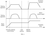
- FIG. 4 is a schematic diagram of working conditions of a braking system according to an embodiment of this application.
- the braking apparatus 30 drives the piston 112 to move rightward, the piston 112 drives the brake caliper 12 to clamp the brake disc gradually, and the hydraulic pressure inside the sealed cavity 1111 gradually increases.
- the driver may activate the parking control button in this process.
- the hydraulic pressure inside the sealed cavity 1111 increases to be equal to the target hydraulic pressure, the motor 21 is started, and a rotation speed of the motor 21 may first increase and then decrease to drive the nut 23 to move rightward.
- the brake caliper 12 can clamp the brake disc by fully depending on abutting action of the nut 23 to implement parking braking of the vehicle.
- clamping force on the brake disc gradually increases and then remains at a fixed value.
- the braking apparatus 30 drives the piston 112 to move rightward again until the second end 1122 of the piston 112 moves to the second position, so that the vehicle is restored from the slipping state to the stationary state. Thereafter, the motor 21 is started to drive the nut 23 to move to the position abutting against the piston 112 again, thereby implementing re-parking braking of the vehicle. Then, the motor 21 stops working, the braking apparatus 30 exits the pressure building, and the hydraulic pressure inside the sealed cavity 1111 gradually reduces to zero. In a process from the slipping state to the re-parking braking, the clamping force on the brake disc increases accordingly and finally remains at a fixed value.
- An embodiment of this application further provides a braking system control method.
- the control method may include the following steps:
- control method may further include:
- the braking apparatus when parking braking is performed, the braking apparatus first generates corresponding braking force, so that the brake caliper clamps the brake disc, and then controls the motor to drive a nut to move to a position abutting against the piston. Assistance is provided by the braking apparatus when parking is performed, so that torque output by the motor of the parking apparatus is small, and power required from the motor is also small. In this case, costs of the motor can be reduced. In addition, a deceleration mechanism for increasing torque can be omitted from the parking apparatus. This can simplify a structure of the parking apparatus, and improve overall NVH performance of a vehicle.
- the braking system control method may further include:
- the first hydraulic apparatus and the second hydraulic apparatus may work in redundancy mode by using this design. When one of the hydraulic apparatuses is faulty, the other may continue to work. This ensures that the vehicle completes an entire parking action and meets a function safety requirement for vehicle running.
- a parking mode of the vehicle may be first determined based on a running status of the vehicle, and then the target hydraulic pressure is calculated based on the determined parking mode.
- the vehicle may still slip under impact of an external environment or action of external force.
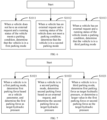
- the foregoing control method may further include a step of a safety mode control policy, so that re-parking braking is performed on the vehicle when slipping occurs. Based on this, refer to FIG. 5 .
- the braking system control method provided in this embodiment of this application may specifically include the following steps.
- Step S101 Determine a parking mode.
- Step S102 Determine target hydraulic pressure based on the parking mode of a vehicle.
- Step S103 In a conventional control mode, control a braking apparatus to drive a piston to move, and control a motor to drive a transmission assembly to move.
- Step S104 When the vehicle is in a slipping state, control a braking system to perform a safety mode control policy.
- FIG. 6 is a specific flowchart of step 101 shown in FIG. 5 .
- Step S101 may specifically include the following steps.
- Step S 1011 When it is determined that a vehicle does not have an external request and a running status of the vehicle meets a parking condition, determine that the vehicle is in a first parking mode.
- Step S1012 When it is determined that a vehicle has an external request and a running status of the vehicle does not meet a parking condition, determine that the vehicle is in a second parking mode.
- Step S 1013 When it is determined that a vehicle has an external request and a running status of the vehicle meets a parking condition, determine that the vehicle is in a third parking mode.
- the external request of the vehicle includes but is not limited to that the vehicle is in an intelligent driving mode, the vehicle is in an anti-lock braking mode, the vehicle is in a driving assistance mode, or the like.
- the parking condition of the vehicle includes whether the vehicle receives a parking instruction and whether the vehicle speed, the wheel speed, a throttle pedal opening degree of the vehicle, and the like meet the requirements.
- Determining that the running status of the vehicle meets the parking condition may specifically include: when it is determined that the vehicle receives the parking instruction, determining, based on facts that the vehicle speed of the vehicle is less than or equal to a parking speed threshold, the wheel speed of the vehicle is less than or equal to a parking wheel speed threshold, the wheel speed of the vehicle is less than or equal to a parking wheel speed threshold, and the throttle pedal opening degree of the vehicle is less than or equal to an opening degree threshold, that the running status of the vehicle meets the parking condition.
- the parking condition is not met as long as one of the foregoing four conditions is not met. For example, if the vehicle does not receive the parking instruction, it is determined that the running status of the vehicle does not meet the parking condition without performing determining on the following three conditions (the vehicle speed, the wheel speed, and the throttle pedal opening degree). When it is determined that the vehicle receives the parking instruction, and the vehicle speed of the vehicle is not less than or not equal to the parking speed threshold, it is determined that the running status of the vehicle does not meet the parking condition without performing determining on the other two conditions (the wheel speed and the throttle pedal opening degree). The rest can be deduced by analogy.
- FIG. 7 is a specific flowchart of step S102 shown in FIG. 5 .
- Step 102 may specifically include the following steps.
- Step S1021 When a vehicle is in a first parking mode, determine first parking force based on a vehicle parameter, where the first parking force is target hydraulic pressure.
- Step S1022 When a vehicle is in a second parking mode, determine second parking force based on an external request, where in this case, the second parking force is target hydraulic pressure.
- Step S1023 When a vehicle is in a third parking mode, determine first parking force as target hydraulic pressure, or determine a larger value in the first parking force or second parking force as the target hydraulic pressure.
- the vehicle parameter includes one or more of a slope of a road on which the vehicle is located, mass of the vehicle, whether the vehicle is provided with a trailer, and whether a temperature of the brake disc is greater than or equal to a temperature threshold.
- FIG. 8 is a specific flowchart of step S103 shown in FIG. 5 .
- Step S103 may specifically include the following steps.
- Step S1031 Control the braking apparatus to drive the piston to move.
- Step S1032 Determine whether the second end of the piston moves to the first position; and if yes, perform step S1033, or if no, return to perform step S1031.
- Step S1033 Control the motor to drive the transmission assembly to move in a direction close to the first end of the piston.
- Step S1034 Determine whether the transmission assembly is in contact with the first end of the piston; and if yes, perform step S1035, or if no, return to perform step 1033.
- Step S103 5 End the control.
- step S104 may specifically include: identifying, based on information such as the wheel speed and a traveling direction of the vehicle, whether the vehicle is in a slipping state; and when it is determined that the vehicle is in the slipping state, controlling the braking apparatus to drive the piston to move to a second position, where the second position is specifically located on a side that is of the first position and that is away from the nut, so that the brake caliper is pushed by the piston to clamp the brake disc again, thereby restoring the vehicle from the slipping state to a stationary state.
- the motor is controlled to drive the screw to rotate, and the screw drives the nut to move to a position abutting against the first end of the piston, to implement re-parking braking of the vehicle.
- an embodiment of this application further provides a computing device 1100.
- the computing device 1100 may be a chip or a chip system.
- the chip system may include a chip, or may include a chip and another discrete component.
- the computing device 1100 may include at least one processor 1110.
- the processor 1110 is coupled to a memory.
- the memory may be located in the apparatus, the memory may be integrated with the processor, or the memory may be located outside the apparatus.
- the computing device 1100 may further include at least one memory 1120.
- the memory 1120 stores a computer program, configuration information, a computer program or instructions, and/or data necessary for implementing any one of the foregoing embodiments.
- the processor 1110 may execute the computer program stored in the memory 1120, to complete the method in any one of the foregoing embodiments.
- the coupling in this embodiment of this application is an indirect coupling or a communication connection between apparatuses, units, or modules, may be in an electrical form, a mechanical form, or another form, and is used for information exchange between the apparatuses, units, or modules.
- the processor 1110 may work with the memory 1120 and the communication interface 1130.
- a specific connection medium between the processor 1110, the memory 1120, and the communication interface 1130 is not limited in embodiments of this application.
- the processor 1110, the memory 1120, and the communication interface 1130 are connected to each other by using a bus 1140.
- the bus 1140 may be a peripheral component interconnect (peripheral component interconnect, PCI) bus, an extended industry standard architecture (extended industry standard architecture, EISA) bus, or the like.
- PCI peripheral component interconnect
- EISA extended industry standard architecture
- the bus may be classified into an address bus, a data bus, a control bus, and the like. For ease of representation, only one thick line is used to represent the bus in FIG. 9 , but this does not mean that there is only one bus or only one type of bus.
- the processor may be a general-purpose processor, a digital signal processor, an application-specific integrated circuit, a field programmable gate array or another programmable logic device, a discrete gate or transistor logic device, or a discrete hardware component, and may implement or execute the methods, steps, and logical block diagrams in embodiments of this application.
- the general-purpose processor may be a microprocessor, any conventional processor, or the like. The steps of the methods in embodiments applied for with reference to embodiments of this application may be directly performed by a hardware processor, or may be performed by using a combination of hardware in the processor and a software module.
- the memory may be a non-volatile memory, like a hard disk drive (hard disk drive, HDD) or a solid-state drive (solid-state drive, SSD), or may be a volatile memory (volatile memory), like a random-access memory (random-access memory, RAM).
- the memory is any other medium that can carry or store expected program code in a form of instructions or a data structure and that can be accessed by a computer, but is not limited thereto.
- the memory in embodiments of this application may alternatively be a circuit or any other apparatus that can implement a storage function, and is configured to store program instructions and/or data.
- the computing device 1100 may be applied to a transmit end.
- the computing device 1100 may be a transmit end, or may be an apparatus that can support the transmit end and implement a function of the transmit end in any one of the foregoing embodiments.
- the memory 1120 stores a computer program and computer program instructions and/or data required for implementing the function of the transmit end in any one of the foregoing embodiments.
- the processor 1110 may execute the computer program stored in the memory 1120, to complete the method performed by the transmit end in any one of the foregoing embodiments.
- the communication interface of the computing device 1100 may be configured to interact with a receive end, for example, send information to the receive end.
- the computing device 1100 may be applied to the receive end.
- the computing device 1100 may be the receive end, or may be an apparatus that can support the receive end and implement a function of the receive end in any one of the foregoing embodiments.
- the memory 1120 stores a computer program and computer program instructions and/or data required for implementing the function of the receive end in any one of the foregoing embodiments.
- the processor 1110 may execute the computer program stored in the memory 1120, to complete the method performed by the receive end in any one of the foregoing embodiments.
- the communication interface of the computing device 1100 may be configured to interact with the transmit end, for example, receive information from the transmit end.
- the computing device 1100 provided in embodiments may be applied to the transmit end to complete the method performed by the transmit end, or may be applied to the receive end to complete the method performed by the receive end. Therefore, for technical effect that can be achieved, refer to the foregoing method embodiments. Details are not described herein again.
- an embodiment of this application further provides a computer program.
- the computer program When the computer program is run on a computer, the computer is enabled to implement the method provided in any embodiment shown in FIG. 5 to FIG. 8 .
- an embodiment of this application further provides a computer-readable storage medium, where the computer-readable storage medium stores a computer program.
- the computer program When the computer program is executed by a computer, the computer is enabled to implement the method provided in the embodiment shown in any one of embodiments shown in FIG. 5 to FIG. 8 .
- the storage medium may be any available medium that can be accessed by the computer.
- Examples of the computer-readable medium include but are not limited to a RAM, a read-only memory (read-only memory, ROM), an electrically erasable programmable read-only memory (electrically erasable programmable read-only memory, EEPROM), a CD-ROM or other optical disc storage, a disk storage medium or other disk storage, or any other medium that can be used to carry or store expected program code in a form of instructions or a data structure and can be accessed by the computer.
- ROM read-only memory
- EEPROM electrically erasable programmable read-only memory
- CD-ROM or other optical disc storage a CD-ROM or other optical disc storage
- disk storage medium or other disk storage or any other medium that can be used to carry or store expected program code in a form of instructions or a data structure and can be accessed by the computer.
- All or some of the technical solutions provided in embodiments of this application may be implemented by using software, hardware, firmware, or any combination thereof.
- software is used for implementation, all or part of the implementation may be implemented in a form of a computer program product.
- the computer program product includes one or more computer instructions.
- the computer may be a general-purpose computer, a dedicated computer, a computer network, an access network device, a terminal device, or another programmable apparatus.
- the computer instructions may be stored in a computer-readable storage medium, or transmitted from one computer-readable storage medium to another computer-readable storage medium.
- the computer instruction may be transmitted from one website, computer, server, or data center to another website, computer, server, or data center in a wired (for example, a coaxial cable, an optical fiber, or a digital subscriber line (digital subscriber line, DSL)) or wireless (for example, infrared, radio, or microwave) manner.
- the computer-readable storage medium may be any usable medium accessible by the computer, or a data storage device like a server or a data center integrated with one or more usable media.
- the usable medium may be a magnetic medium (for example, a floppy disk, a hard disk, or a magnetic tape), an optical medium (for example, a digital video disc (digital video disc, DVD)), a semiconductor medium, or the like.
Landscapes
- Engineering & Computer Science (AREA)
- Transportation (AREA)
- Mechanical Engineering (AREA)
- Braking Systems And Boosters (AREA)
- Regulating Braking Force (AREA)
Abstract
Description
- This application relates to the field of vehicle technologies, and in particular, to a braking system, a vehicle, and a braking system control method.
- When a vehicle is stopped, parking braking is usually performed to avoid slipping. In a manner of parking braking, a handbrake and an electric parking brake (electrical park brake, EPB) are usually included. A conventional handbrake is of a cable-pulling type, and a user may transfer parking force to a parking apparatus by pulling a handbrake lever. A degree of pulling up the handbrake lever determines an amount of the parking force. Compared with that of the conventional handbrake, an operation mode of the electric parking brake is changed to pressing a button switch. A command is sent to a control unit of an electric parking brake apparatus by pressing or lifting the button. The control unit controls a brake caliper to apply parking force to a brake disc to implement parking braking.
- Some electric parking brake apparatuses are usually provided with a deceleration mechanism. When parking braking is performed, power output by a motor needs to be transmitted to the brake caliper after deceleration and torque increase are performed on the power by the deceleration mechanism, so that the brake caliper clamps the brake disc. Similarly, when the parking braking is released, power output by the motor through reverse rotation is also transmitted to the brake caliper through the deceleration mechanism, so that the brake caliper releases the brake disc. Because of the deceleration mechanism, a structure of the electric parking brake apparatus is complex, a size of the electric parking brake apparatus is large, and noise is obvious in a process of parking or releasing the parking. This affects noise, vibration, and harshness (noise, vibration, and harshness, NVH) performance of the vehicle.
- This application provides a braking system, a vehicle, and a braking system control method, to simplify a structure of the braking system and improve NVH performance of the vehicle on a premise of implementing reliable parking.
- According to a first aspect, this application provides a braking system. The braking system may include a brake cylinder, a braking apparatus, and a parking apparatus. The brake cylinder may include a piston, the piston is movably disposed in a cylinder body, a first end of the piston may be located in the brake cylinder, and a second end of the piston may extend out of the brake cylinder. The braking apparatus is connected to the brake cylinder, and the braking apparatus may drive the piston to move. The parking apparatus may include a motor and a transmission assembly, an output shaft of the motor may be directly connected to the transmission assembly, and the transmission assembly is at least partially disposed in the brake cylinder. The motor may be configured to drive the transmission assembly to move in the brake cylinder, to enable the transmission assembly to be in contact with or separate from the first end of the piston.
- In the foregoing solution, assistance is provided by the braking apparatus when the braking system is used to perform parking, so that torque output by the motor of the parking apparatus is small, and power required from the motor is also small. In this case, costs of the motor can be reduced. In addition, a deceleration mechanism for increasing torque can be omitted from the parking apparatus. This can simplify a structure of the parking apparatus, and improve overall NVH performance of a vehicle.
- For example, the transmission assembly may include a screw and a nut, the output shaft of the motor may be directly connected to the screw, the screw may extend into the brake cylinder, the nut is located in the brake cylinder, and the nut and the screw are in threaded connection. In this way, when the motor drives the screw to rotate, the screw can drive the nut to move, so that the nut can be in contact with or separate from the first end of the piston.
- During specific disposition, an axial direction of the screw may be consistent with a length direction of the cylinder body, so that a moving direction of the nut in the cylinder body is also consistent with a moving direction of the piston. In this way, when the nut abuts against the first end of the piston, a direction of force applied by the nut to the piston is in consistent with the moving direction of the piston. This can reduce a risk of piston jamming.
- In addition, the first end of the nut may be provided with an opening, an end part of the screw may extend into the opening, the nut is mounted at the end part of the screw, and therefore the nut is also located in the opening. When the motor drives the screw to rotate to drive the nut to move, the nut may abut against the bottom of the opening, to apply force to the piston in a direction away from the motor.
- In some possible implementations, the braking system may further include a brake caliper and a brake disc. The brake caliper is connected to the second end of the piston, and the brake disc may be disposed in clamping space of the brake caliper, so that when the piston moves, the brake caliper can be driven to clamp or loosen the brake disc.
- In some possible implementations, the brake caliper may include two friction blocks that are disposed oppositely. The two friction blocks may be respectively disposed on two sides of the brake disc, the two friction blocks are in transmission connection, and may move toward or against each other when external force is applied. This changes a size of the clamping space of the brake caliper.
- In some possible implementations, the braking system may further include a control unit, and the control unit may be configured to: obtain a parking signal, and control, based on the parking signal, the braking apparatus to drive the piston to move; and when the piston moves to a first position, control the motor to drive the transmission assembly to move to a position abutting against the first end of the piston.
- In some possible implementations, the control unit may be further configured to: obtain hydraulic pressure inside the brake cylinder, and when the hydraulic pressure inside the brake cylinder is not less than target hydraulic pressure, control the second end of the piston to move to the first position. It may be understood that the first position is a position at which the second end of the piston is located when the brake caliper clamps the brake disc so that the brake disc stops rotating.
- In some possible implementations, the braking apparatus may include a first hydraulic apparatus and a second hydraulic apparatus, and the first hydraulic apparatus and the second hydraulic apparatus may be separately connected to the brake cylinder. The control unit is further configured to: when the first hydraulic apparatus is faulty, control the second hydraulic apparatus to drive the piston to move; or when the second hydraulic apparatus is faulty, control the first hydraulic apparatus to drive the piston to move; or when neither the first hydraulic apparatus nor the second hydraulic apparatus is faulty, control the first hydraulic apparatus and the second hydraulic apparatus to jointly drive the piston to move. In other words, the first hydraulic apparatus and the second hydraulic apparatus may work together or work in redundancy mode. In this way, even if one of the hydraulic apparatuses is faulty, normal operation of the entire braking apparatus can be ensured, thereby improving reliability of the braking apparatus.
- In some possible implementations, the control unit may be further configured to: obtain a running status of the vehicle, determine a parking mode of the vehicle based on the running status of the vehicle, and determine the target hydraulic pressure based on the parking mode. The target hydraulic pressure may be determined more accurately based on the running status of the vehicle and by using this design, so that the vehicle can perform reliable parking braking.
- When determining the parking mode of the vehicle, the control unit may be further configured to: when the vehicle does not have an external request and the running status of the vehicle meets a parking condition, determine a first parking mode, and determine first parking force based on a vehicle parameter, where the first parking force is the target hydraulic pressure; or when the vehicle has an external request and the running status of the vehicle does not meet a parking condition, determine a second parking mode, and determine second parking force based on the external request, where the second parking force is the target hydraulic pressure; or when the vehicle has an external request and the running condition of the vehicle meets a parking condition, determine a third parking mode, and determine first parking force as the target hydraulic pressure, or determine a larger value in the first parking force and second parking force as the target hydraulic pressure.
- The external request of the vehicle includes but is not limited to that the vehicle is in an intelligent driving mode, the vehicle is in an anti-lock braking mode, the vehicle is in a driving assistance mode, or the like. The vehicle parameter includes one or more of a slope of a road on which the vehicle is located, mass of the vehicle, whether the vehicle is provided with a trailer, or a temperature of the brake disc.
- When determining whether the running status of the vehicle meets the parking condition, the control unit may be further configured to: when the vehicle receives a parking instruction, determine, based on facts that a vehicle speed of the vehicle is less than or equal to a parking speed threshold, a wheel speed of the vehicle is less than or equal to a parking wheel speed threshold, and a throttle pedal opening degree of the vehicle is less than or equal to an opening degree threshold, that the running status of the vehicle meets the parking condition.
- In some possible implementations, the control unit may be further configured to: when the vehicle is in a slipping state, control the braking apparatus to drive the piston to move, to restore the vehicle from the slipping state to a stationary state; and when the second end of the piston moves to a second position, control the motor to drive the screw to rotate, and the screw drives the nut to move to a position abutting against the first end of the piston, to fasten a position of the piston and implement re-parking braking of the vehicle. It may be understood that the second position is located on a side that is of the first position and that is away from the first end of the piston.
- According to a second aspect, this application provides a braking system control method. The braking system may include a brake cylinder, a braking apparatus, and a parking apparatus. The brake cylinder may include a piston, the piston is movably disposed in a cylinder body, a first end of the piston may be located in the brake cylinder, and a second end of the piston may extend out of the brake cylinder. The braking apparatus is connected to the brake cylinder, and the braking apparatus may drive the piston to move. The parking apparatus may include a motor and a transmission assembly, an output shaft of the motor may be directly connected to the transmission assembly, and the transmission assembly is at least partially disposed in the brake cylinder. The motor may be configured to drive the transmission assembly to move in the brake cylinder, to enable the transmission assembly to be in contact with or separate from the first end of the piston. The control method may include:
- obtaining a parking signal;
- controlling, based on the parking signal, the braking apparatus to drive the piston to move; and
- when a second end of the piston moves to a first position, controlling the motor to drive the transmission assembly to move to a position abutting against the first end of the piston.
- According to the braking system control method provided in this embodiment of this application, assistance is provided by the braking apparatus when parking is performed, so that torque output by the motor of the parking apparatus is small, and power required from the motor is also small. In this case, costs of the motor can be reduced. In addition, a deceleration mechanism for increasing torque can be omitted from the parking apparatus. This can simplify a structure of the parking apparatus, and improve overall NVH performance of the vehicle.
- In some possible implementations, the control method may further include: obtaining hydraulic pressure inside the brake cylinder, and when the hydraulic pressure inside the brake cylinder is not less than target hydraulic pressure, controlling the second end of the piston to move to the first position. It may be understood that the first position is a position at which the second end of the piston is located when the brake caliper clamps the brake disc so that the brake disc stops rotating.
- In some possible implementations, the braking apparatus may include a first hydraulic apparatus and a second hydraulic apparatus, and the first hydraulic apparatus and the second hydraulic apparatus may be separately connected to the brake cylinder. The controlling the braking apparatus to drive the piston to move may specifically include:
when the first hydraulic apparatus is faulty, controlling the second hydraulic apparatus to drive the piston to move; or when the second hydraulic apparatus is faulty, controlling the first hydraulic apparatus to drive the piston to move; or when neither the first hydraulic apparatus nor the second hydraulic apparatus is faulty, controlling the first hydraulic apparatus and the second hydraulic apparatus to jointly drive the piston to move. In other words, the first hydraulic apparatus and the second hydraulic apparatus may work together or work in redundancy mode. In this way, even if one of the hydraulic apparatuses is faulty, normal operation of the entire braking apparatus can be ensured, thereby improving reliability of the braking apparatus. - In some possible implementations, the control method may further include:
obtaining a running status of a vehicle, determining a parking mode of the vehicle based on the running status of the vehicle, and determining the target hydraulic pressure based on the parking mode. The target hydraulic pressure may be determined more accurately based on the running status of the vehicle and by using this design, so that the vehicle can perform reliable parking braking. - The determining a parking mode of the vehicle based on the running status of the vehicle, and determining the target hydraulic pressure based on the parking mode may specifically include:
- when the vehicle does not have an external request and the running status of the vehicle meets a parking condition, determining a first parking mode, and determining first parking force based on a vehicle parameter, where the first parking force is the target hydraulic pressure; or
- when the vehicle has an external request, and the running status of the vehicle does not meet a parking condition, determining a second parking mode, and determining second parking force based on the external request, where the second parking force is the target hydraulic pressure; or
- when the vehicle has an external request and the running condition of the vehicle meets a parking condition, determining a third parking mode, and determining first parking force as the target hydraulic pressure, or determining a larger value in the first parking force and second parking force as the target hydraulic pressure.
- In some possible implementations, the control method may further include:
when the vehicle receives a parking instruction, determining, based on facts that a vehicle speed of the vehicle is less than or equal to a parking speed threshold, a wheel speed of the vehicle is less than or equal to a parking wheel speed threshold, and a throttle pedal opening degree of the vehicle is less than or equal to an opening degree threshold, that the running status of the vehicle meets the parking condition. - In some possible implementations, the control method may further include:
- when the vehicle is in a slipping state, controlling the braking apparatus to drive the piston to move, to restore the vehicle from the slipping state to a stationary state; and
- when the second end of the piston moves to a second position, controlling the motor to drive the transmission assembly to move to a position abutting against the first end of the piston, to fasten a position of the piston and implement re-parking braking of the vehicle. The second position is located on a side that is of the first position and that is away from the first end of the piston.
- According to a third aspect, this application further provides a computing device. The computing device includes a processor, configured to implement the method described in the second aspect. The computing device may further include a memory, configured to store program instructions and data. The memory is coupled to the processor. When executing the program instructions stored in the memory, the processor can implement the method described in the second aspect. The communication apparatus may further include a communication interface. The communication interface is used by the apparatus to communicate with another device. For example, the communication interface may be a transceiver, a circuit, a bus, a module, or another type of communication interface.
- According to a fourth aspect, an embodiment of this application further provides a computer-readable storage medium, where the computer-readable storage medium stores a computer program or instructions. When the computer program or the instructions are run on a computer, the computer is enabled to implement the method according to the second aspect.
- According to a fifth aspect, an embodiment of this application further provides a computer program. When the computer program is run on a computer, the computer is enabled to perform the method according to the second aspect.
- According to a sixth aspect, this application further provides a braking system control apparatus, where the braking system control apparatus may include an obtaining unit and a processing unit.
- The obtaining unit is configured to obtain a parking signal.
- The processing unit is configured to: control, based on the parking signal, a braking apparatus to drive a piston of a brake cylinder to move, where the piston has a first end located in the brake cylinder and a second end extending out of the brake cylinder; and when the second end of the piston moves to a first position, control a motor of a parking apparatus to drive a transmission assembly to move to a position abutting against the first end of the piston, where the transmission assembly is at least partially located in the brake cylinder.
- In some possible implementations, the processing unit may be further configured to:
obtain hydraulic pressure inside the brake cylinder; and when the hydraulic pressure inside the brake cylinder is greater than or equal to target hydraulic pressure, determine that the second end of the piston moves to the first position. - In some possible implementations, the processing unit may be specifically configured to:
when a first hydraulic apparatus is faulty, control a second hydraulic apparatus to drive the piston to move; or when a second hydraulic apparatus is faulty, control a first hydraulic apparatus to drive the piston to move; or when neither a first hydraulic apparatus nor a second hydraulic apparatus is faulty, control the first hydraulic apparatus and the second hydraulic apparatus to jointly drive the piston to move. - In some possible implementations, the obtaining unit may be further configured to obtain a running status of the vehicle.
- The processing unit may be further configured to: determine a parking mode of the vehicle based on the running status of the vehicle, and determine the target hydraulic pressure based on the parking mode.
- In some possible implementations, the processing unit may be further configured to:
- when the vehicle does not have an external request and the running status of the vehicle meets a parking condition, determine a first parking mode, and determine first parking force based on a vehicle parameter, where the first parking force is the target hydraulic pressure; or
- when the vehicle has an external request, and the running status of the vehicle does not meet a parking condition, determine a second parking mode, and determine second parking force based on the external request, where the second parking force is the target hydraulic pressure; or
- when the vehicle has an external request and the running condition of the vehicle meets a parking condition, determine a third parking mode, and determine first parking force as the target hydraulic pressure, or determine a larger value in the first parking force and second parking force as the target hydraulic pressure.
- In some possible implementations, the processing unit may be further configured to:
when the vehicle receives a parking instruction, determine, based on facts that a vehicle speed of the vehicle is less than or equal to a parking speed threshold, a wheel speed of the vehicle is less than or equal to a parking wheel speed threshold, and a throttle pedal opening degree of the vehicle is less than or equal to an opening degree threshold, that the running status of the vehicle meets the parking condition. - In some possible implementations, the processing unit may be further configured to:
- when the vehicle is in a slipping state, control the braking apparatus to drive the piston to move; and
- when the second end of the piston moves to the first position, control the transmission assembly to move to a position abutting against the first end of the piston, where
- the second position is located on a side that is of the first position and that is away from the first end of the piston.
- According to a seventh aspect, this application further provides a vehicle. The vehicle may include wheels and the braking system in any one of the foregoing possible technical solutions. The braking system is in transmission connection to the wheels, to apply braking force to the wheels, so that the vehicle implements parking braking or braking release. A structure of the braking system of the vehicle is simple, and NVH performance of the vehicle is improved.
-
-
FIG. 1 is a schematic diagram of a structure of a vehicle according to an embodiment of this application; -
FIG. 2 is a schematic diagram of a partial structure of a braking system according to an embodiment of this application; -
FIG. 3 is a schematic diagram of a structure of a braking apparatus according to an embodiment of this application; -
FIG. 4 is a schematic diagram of working conditions of a braking system according to an embodiment of this application; -
FIG. 5 is a flowchart of a braking system control method according to an embodiment of this application; -
FIG. 6 is a specific flowchart of step 101 shown inFIG. 5 ; -
FIG. 7 is a specific flowchart of step 102 shown inFIG. 5 ; -
FIG. 8 is a specific flowchart ofstep 103 shown inFIG. 5 ; and -
FIG. 9 is a schematic diagram of a structure of a braking system control apparatus according to an embodiment of this application. -
- 1: Vehicle; 100: Power assembly system; 200: Braking system; 300: Wheel; 10: Brake; 11: Brake cylinder;
- 12: Brake caliper; 111: Cylinder body; 112: Piston; 1121: First end of the piston; 1122: Second end of the piston;
- 1111: Sealed cavity; 121: Clamping space; 122: Friction block; 21: Motor; 22: Screw; 23: Nut; 1123: Opening;
- 31: First hydraulic apparatus; 32: Second hydraulic apparatus; 311: First controller; 312: Master cylinder;
- 313: Pedal feel simulator; 314: Oil tank; 315: Travel sensor; 321: Second controller; 322: Three-phase motor;
- 323: Electric cylinder; 324: Motor position sensor; 40: Brake pedal; 1100: Computing device; 1110: Processor;
- 1120: Memory; 1130: Communication interface; 1140: Bus.
- To make the objectives, technical solutions, and advantages of this application clearer, the following further describes this application in detail with reference to the accompanying drawings. Reference to "an embodiment", "some embodiments", or the like described in this specification indicates that one or more embodiments of this application include a specific feature, structure, or characteristic described with reference to the embodiment. Therefore, statements such as "in an embodiment", "in some embodiments", "in some other embodiments", and "in other embodiments" that appear at different places in this specification do not necessarily mean referring to a same embodiment. Instead, the statements mean "one or more but not all of embodiments", unless otherwise specifically emphasized in another manner. The terms "include", "comprise", "have", and their variants all mean "include but is not limited to", unless otherwise specifically emphasized. In addition, words such as "first" and "second" in this specification are merely used for distinguishing description, and shall not be understood as an indication or implication of relative importance or an indication or implication of an order.
- Terms used in the following embodiments are merely intended to describe specific embodiments, but are not intended to limit this application. The terms "one", "a" and "this" of singular forms used in this specification and the appended claims of this application are also intended to include expressions such as "one or more", unless otherwise specified in the context clearly.
-
FIG. 1 is a schematic diagram of a structure of a vehicle according to an embodiment of this application. Refer toFIG. 1 . Avehicle 1 may include apower assembly system 100, abraking system 200, andwheels 300. Thepower assembly system 100 may be in transmission connection to thewheels 300, to provide driving force to thewheels 300 to drive thevehicle 1 to travel. Thebraking system 200 may include braking apparatuses, parking apparatuses, and brakes. The brakes may be disposed in a one-to-one correspondence with thewheels 300, and each brake may be disposed at a corresponding wheel. The braking apparatuses may respectively be in transmission connection to the brakes at the correspondingwheels 300 to provide braking force to thewheels 300 through the brakes, to stop thevehicle 1 during traveling. The parking apparatuses may also be disposed in a one-to-one correspondence with thewheels 300, and each parking apparatus may be in transmission connection to the brake at thecorresponding wheel 300 to provide parking force to the wheel through thebrake 300, to avoid slipping of the stoppedvehicle 1. - In some embodiments, the
vehicle 1 may be a fuel vehicle. In this case, thepower assembly system 100 may specifically include components like an engine, a decelerator, and a transmission gearbox. Driving force output by the engine may be transmitted to the decelerator, and then transmitted to the transmission gearbox after deceleration and torque increase are performed on the driving force by the decelerator. Then, the driving force is output to thewheels 300 after being changed by the transmission gearbox based on a gear setting of thevehicle 1, to drive thevehicle 1 to travel. - In some other embodiments, the
vehicle 1 may alternatively be an electric vehicle. In this case, thepower assembly system 100 may specifically include a motor and a decelerator. Driving force output by the motor may be transmitted to the decelerator, and is output to thewheels 300 after deceleration and torque increase are performed on the driving force by the decelerator, to drive thevehicle 1 to travel. -
FIG. 2 is a schematic diagram of a partial structure of a braking system according to an embodiment of this application. Refer toFIG. 2 . Abrake 10 may include abrake cylinder 11, abrake caliper 12, and a brake disc (not shown in the figure). The brake cylinder may include acylinder body 111 and apiston 112. Thepiston 112 may be movably disposed in thecylinder body 111, and thepiston 112 is in contact with an inner wall of thecylinder body 111. During specific implementation, one end of thecylinder body 111 may be a closed end, and the other end may be an open end. Afirst end 1121 of thepiston 112 may be disposed toward the closed end of thecylinder body 111, and a sealedcavity 1111 is formed between thefirst end 1121 of thepiston 112 and the closed end of thecylinder body 111. Asecond end 1122 of thepiston 112 may extend out of thebrake cylinder 11 through the open end of thecylinder body 111. Thebrake caliper 12 is connected to thesecond end 1122 of thepiston 112, and the brake disc may be disposed in clampingspace 121 of thebrake caliper 12. The brake disc is fixedly connected to a wheel. In this way, when thepiston 112 moves in thecylinder body 111, thesecond end 1122 of thepiston 112 may drive thebrake caliper 12 to clamp or release the brake disc, to implement braking or parking braking of the vehicle by applying braking force to the brake disc when thebrake caliper 12 clamps the brake disc, and release braking of the vehicle when thebrake caliper 12 releases the brake disc. - The
brake caliper 12 may include two friction blocks 122 that are disposed oppositely, and the two friction blocks 122 may be respectively disposed on two sides of the brake disc. The two friction blocks 122 are in transmission connection by using a connector, and the two friction blocks 122 may simultaneously move toward or against each other under action of external force. It may be understood that a gap between the two friction blocks 122 is the clampingspace 121 of the brake caliper. - In addition, in this embodiment of this application, a relationship between a moving direction of the
piston 112 and a working state of thebrake caliper 12 may be specifically as follows: When thepiston 112 moves in a direction away from the closed end of thecylinder body 111, the two friction blocks 122 of thebrake caliper 12 move toward each other, that is, the clampingspace 121 of thebrake caliper 12 shrinks, so that thebrake caliper 12 can clamp the brake disc when thepiston 112 moves to a specific position. When thepiston 112 moves in a direction close to the closed end of thecylinder body 111, the two friction blocks 122 of thebrake caliper 12 move against each other, that is, the clampingspace 121 of thebrake caliper 12 expands, so that thebrake caliper 12 may release the brake disc. - Still refer to
FIG. 2 . Aparking apparatus 20 may include amotor 21 and a transmission assembly, themotor 21 is located outside the brake cylinder, the transmission assembly is directly connected to an output shaft of themotor 21, and the transmission assembly may be at least partially located in thebrake cylinder 11. The transmission assembly may be specifically a structure that can change a rotating motion into a linear motion. In this way, when the output shaft of themotor 21 rotates, a part of the transmission assembly that is located in thebrake cylinder 11 may be driven to move. For example, the transmission assembly may include ascrew 22 and anut 23, one end of thescrew 22 is directly connected to the output shaft of themotor 21, and the other end may extend into the sealedcavity 1111 of thecylinder body 111. During specific implementation, a through hole may be disposed at the closed end of thecylinder body 111, and thescrew 22 may specifically extend into the sealedcavity 1111 through the through hole. Thenut 23 is disposed in the sealedcavity 1111 and is mounted on thescrew 22. In other words, thenut 23 and thescrew 22 are in threaded connection. In this way, when themotor 21 drives thescrew 22 to rotate, thenut 23 that is mounted on thescrew 22 may move in an axial direction of thescrew 22. In this embodiment of this application, the axial direction of thescrew 22 may be consistent with a length direction of thecylinder body 111, so that a moving direction of thenut 23 in thecylinder body 111 is consistent with the moving direction of thepiston 112. - It should be understood that, the moving direction of the
nut 23 is determined by a rotation direction of themotor 21, and thenut 23 may move rightward or leftward by controlling forward or reverse rotation of themotor 21. The rightward movement is moving in the direction away from the closed end of thecylinder body 111. The leftward movement is moving in the direction close to the closed end of thecylinder body 111. For example, it may be set that when themotor 21 rotates forward, thenut 23 moves rightward, and when themotor 21 rotates reversely, thenut 23 moves leftward. - In some embodiments, the
nut 23 may be mounted at an end part of thescrew 22. For example, thenut 23 may be a cap-shaped structure with one end closed. In this way, after thenut 23 is mounted on thescrew 22, the closed end of thenut 23 may always protrude from the end part of thescrew 22. In addition, in this embodiment, thefirst end 1121 of thepiston 112 may be provided with anopening 1123, and the end part of thescrew 22 may extend into theopening 1123. In this case, thenut 23 is also located in theopening 1123. When themotor 21 rotates forward and drives thescrew 22 to rotate, thenut 23 moves rightward, and the closed end of thenut 23 may approach or abut against the bottom of theopening 1123, to apply force in a direction away from the closed end of thecylinder body 111 to thepiston 112. When themotor 21 rotates reversely and drives thescrew 22 to rotate, thenut 23 moves leftward, and the closed end of thenut 23 moves away from the bottom of theopening 1123, to relieve the force applied to thepiston 112. - In this embodiment of this application, the braking apparatus may specifically control an action of the
brake 10 in a hydraulic driving manner. The braking apparatus may be connected to the sealedcavity 1111 of thebrake cylinder 11, and thepiston 112 is driven to move leftward and rightward by controlling a flow of oil that flows into the sealedcavity 1111, to control the working state of thebrake caliper 12 by using thepiston 112. Specifically, when oil in the braking apparatus flows into the sealedcavity 1111 of thebrake cylinder 11, hydraulic pressure inside the sealedcavity 1111 increases, and thepiston 112 may move rightward, to drive thebrake caliper 12 to clamp the brake disc, thereby implementing braking of the wheels. When the oil in the braking apparatus flows out of the sealedcavity 1111 of thebrake cylinder 11, the hydraulic pressure inside the sealedcavity 1111 decreases, and thepiston 112 may move leftward, to release braking force applied to the brake disc. -
FIG. 3 is a schematic diagram of a structure of a braking apparatus according to an embodiment of this application. Refer toFIG. 3 . Abraking apparatus 30 may include two sets of hydraulic apparatuses, a firsthydraulic apparatus 31 and a secondhydraulic apparatus 32. The firsthydraulic apparatus 31 may be specifically an intelligent braking system (intelligent braking system, IBS), and the secondhydraulic apparatus 32 may be specifically a redundant brake unit (redundant brake unit, RBU). The firsthydraulic apparatus 31 and the secondhydraulic apparatus 32 are separately connected to a brake cylinder of a brake, and can work together to control operation of the brake to improve control precision of pressure inside the brake cylinder. Alternatively, the firsthydraulic apparatus 31 and the secondhydraulic apparatus 32 may separately control the operation of the brake. In other words, the firsthydraulic apparatus 31 and the secondhydraulic apparatus 32 may work in redundancy mode. In this way, even if one of the hydraulic apparatuses is faulty, normal operation of theentire braking apparatus 30 can be ensured, thereby improving reliability of thebraking apparatus 30. - During specific implementation, the first
hydraulic apparatus 31 may include afirst controller 311, amaster cylinder 312, apedal feel simulator 313, anoil tank 314, atravel sensor 315, a liquid level sensor, a solenoid valve, a check valve, a brake pipe, and the like. The secondhydraulic apparatus 32 may include asecond controller 321, a three-phase motor 322, anelectric cylinder 323, amotor position sensor 324, a solenoid valve, a check valve, a pressure sensor, a brake pipe, and the like. In addition, the braking apparatus may further include at least various solenoid valve drives, motor drives, and various signal processing and control output interfaces. Thefirst controller 311 and thesecond controller 321 may receive measurement or detection signals, including information such as environmental conditions, driver input, and braking system statuses, of various sensors, and control braking features of thebraking apparatus 30 through calculation and judgment. - When the first
hydraulic apparatus 31 works with the secondhydraulic apparatus 32, thefirst controller 311 may control a solenoid valve a and a solenoid valve b to open, and control a solenoid valve c and a solenoid valve d to close. Abrake pedal 40 pushes oil in themaster cylinder 312 to flow into thepedal feel simulator 313 through the solenoid valve b. In addition, thefirst controller 311 collects a signal of thetravel sensor 315, a signal of a pressure sensor at themaster cylinder 312, and an oil level signal of theoil tank 314, and transmits the signals to thesecond controller 321 through a signal interface. Thesecond controller 321 determines a braking intention of a driver based on the signal of thetravel sensor 315 and the signal of the pressure sensor at themaster cylinder 312 that are transmitted by thefirst controller 311, controls the three-phase motor 322 to push a piston in theelectric cylinder 323 to move rightward, and controls a solenoid valve e, a solenoid valve f, a solenoid valve g, a solenoid valve h, a solenoid valve i, a solenoid valve j, a solenoid valve k, and a solenoid valve l to open. One part of oil in a right cavity of theelectric cylinder 323 is divided into two flows. One flow of the oil flows into brake cylinders at two wheels (namely, the front left (front left, FL) wheel and the rear right (rear right, RR) wheel) through the opened solenoid valve e, solenoid valve f, and solenoid valve g. The other flow of the oil flows into brake cylinders at the other two wheels (namely, the rear left (rear left, RL) wheel and the front right (front right, FR) wheel) through the opened solenoid valve h, solenoid valve i, and solenoid valve j. This implements braking of the four wheels. The other part of oil in the right cavity of theelectric cylinder 323 flows into a left cavity of theelectric cylinder 323 through the opened solenoid valve k and solenoid valve l. - It should be noted that, when pressure inside a brake cylinder at a specific wheel is too high, the
second controller 321 may control a solenoid valve (namely, one of the foregoing solenoid valve f, solenoid valve g, solenoid valve i, and solenoid valve j) that is connected to the electric cylinder and the master cylinder and that is at the brake cylinder to close, and control a solenoid valve (one of the foregoing solenoid valve m, solenoid valve n, solenoid valve o, and solenoid valve p) that is connected to theoil tank 314 and that is at the brake cylinder to open. This enables oil in the brake cylinder to flow into theoil tank 314 and implements pressure relief. For example, when pressure inside the brake cylinder at the front left FL wheel is too high, the solenoid valve f may be closed, an oil passage between the right cavity of theelectric cylinder 323 and the brake cylinder at the FL wheel may be cut off, and the solenoid valve m may be opened. In this way, oil in the brake cylinder at the FL wheel flows into the oil tank through the solenoid valve m. - When the second
hydraulic apparatus 32 is faulty, for example, when themotor 322 or theelectric cylinder 323 is faulty, thefirst controller 311 may control the solenoid valve a, the solenoid valve b, the solenoid valve c, and the solenoid valve d to open. A part of oil in themaster cylinder 312 flows into the brake cylinders at two of the wheels (namely, FL wheel and RR wheel) through the opened solenoid valve c, solenoid valve f and solenoid valve g. The other part of oil flows into the brake cylinders at the other two wheels (namely, RL wheel and FR wheel) through the opened solenoid valve d and solenoid valve i and j. This implements braking of the four wheels. - When the first hydraulic apparatus is faulty, for example, when the
master cylinder 312 or thepedal feel simulator 313 is faulty, thefirst controller 311 may collect the signal of thetravel sensor 315 and the level signal of theoil tank 314, and transmit the signals to thesecond controller 312 through the signal interface. Thesecond controller 312 controls, based on the signal of thetravel sensor 315 transmitted by thefirst controller 311, the three-phase motor 322 to push the piston in theelectric cylinder 323 to move rightward, and controls the solenoid valve e, the solenoid valve f, the solenoid valve g, the solenoid valve h, the solenoid valve i, the solenoid valve j, the solenoid valve k, and the solenoid valve l to open. One part of the oil in the right cavity of theelectric cylinder 323 is divided into two flows. One flow of the oil flows into the brake cylinders at two wheels (namely, the FL wheel and the RR wheel) through the opened solenoid valve e, solenoid valve f, and solenoid valve g. The other flow of the oil flows into the brake cylinders at the other two wheels (namely, the RL wheel and the FR wheel) through the opened solenoid valve h, solenoid valve i, and solenoid valve j. This implements braking of the four wheels. The other part of oil in the right cavity of theelectric cylinder 323 flows into the left cavity of theelectric cylinder 323 through the opened solenoid valve k and solenoid valve l. - Refer to
FIG. 2 andFIG. 3 . In this embodiment of this application, thebraking system 200 may further include a control unit. The control unit may be separately electrically connected to thebraking apparatus 30 and theparking apparatus 20. The control unit may be configured to: obtain a parking signal of the vehicle; control, based on the parking signal, thebraking apparatus 30 to drive thepiston 112 to move to apply braking force to the brake disc; and when thesecond end 1122 of thepiston 112 moves to a first position, control themotor 21 to drive thescrew 22 to rotate, to drive, through thescrew 22, thenut 23 to move, thereby enabling thenut 23 to abut against thefirst end 1121 of thepiston 112. In other words, the closed end of thenut 23 abuts against the bottom of the opening of thepiston 1123, so that thepiston 112 is fastened in a current position, and thebrake caliper 12 is kept in a working state of clamping the brake disc. This implements parking braking of the vehicle. In addition, the control unit may be further configured to: obtain hydraulic pressure inside the brake cylinder 11 (namely, the hydraulic pressure inside the sealed cavity 1111), and when it is determined that the hydraulic pressure inside thebrake cylinder 11 is not less than target hydraulic pressure, control thesecond end 1122 of thepiston 112 to move to the first position. In other words, when the braking system in this application performs parking braking, thebraking apparatus 30 first generates corresponding target hydraulic pressure to push thepiston 112 to move, so that thebrake caliper 12 clamps the brake disc, and then controls themotor 21 to drive thenut 23 to move to a position abutting against thepiston 112. Assistance is provided by thebraking apparatus 30 when parking is performed, so that torque output by themotor 21 of theparking apparatus 20 is small, and power required from themotor 21 is also small. In this case, costs of themotor 21 can be reduced. In addition, a deceleration mechanism for increasing torque can be omitted from theparking apparatus 20. This can simplify a structure of theparking apparatus 20, and improve overall NVH performance of the vehicle. - It should be noted that after the
nut 23 moves to a position abutting against thefirst end 1121 of thepiston 112, the control unit may control themotor 21 to stop working, and then control thebraking apparatus 30 to stop applying the braking force to the brake disc. In other words, the control unit controls the firsthydraulic apparatus 31 and the secondhydraulic apparatus 32 to exit pressure building, and thebrake caliper 12 can clamp the brake disc by fully depending on abutting action of thenut 23. - In some implementations, the control unit is further configured to: when it is determined that the first
hydraulic apparatus 31 is faulty, control the secondhydraulic apparatus 32 to drive the piston to move; similarly, when it is determined that the secondhydraulic apparatus 32 is faulty, control the firsthydraulic apparatus 31 to drive the piston to move; and when it is determined that neither the firsthydraulic apparatus 31 nor the secondhydraulic apparatus 32 is faulty, control the firsthydraulic apparatus 31 and the secondhydraulic apparatus 32 to jointly drive the piston to move. The firsthydraulic apparatus 31 and the secondhydraulic apparatus 32 may work in redundancy mode by using this design. When one of the hydraulic apparatuses is faulty, the other may continue to work. This ensures that the vehicle completes an entire parking action and meets a function safety requirement for vehicle running. - In this embodiment of this application, the control unit may be further configured to: obtain a running status of the vehicle, determine a parking mode of the vehicle based on the running status of the vehicle, and determine the target hydraulic pressure based on the parking mode. It should be noted that the target hydraulic pressure of the vehicle determines a position of the second end of the piston, and further determines force applied to the brake disc when the vehicle remains in a parked state. The target hydraulic pressure of the vehicle is related to the running status of the vehicle. For example, that whether the vehicle has an external request, and information, for example, a vehicle speed and a wheel speed of the vehicle, directly affect target parking force.
- When determining the parking mode of the vehicle, the control unit may be further configured to: determine whether the vehicle has the external request; when it is determined that the vehicle does not have the external request and the running status of the vehicle meets a parking condition, determine that the vehicle is in a first parking mode, and determine first parking force based on a vehicle parameter, where the first parking force is the target hydraulic pressure; or when it is determined that the vehicle has the external request, and the running status of the vehicle does not meet a parking condition, determine that the vehicle is in a second parking mode, and determine second parking force based on the external request, where the second parking force is the target hydraulic pressure; or when it is determined that the vehicle has the external request and the running condition of the vehicle meets a parking condition, determine that the vehicle is in a third parking mode, and determine first parking force as the target hydraulic pressure, or determine a larger value in the first parking force and second parking force as the target hydraulic pressure.
- The external request of the vehicle includes but is not limited to that the vehicle is in an intelligent driving mode, the vehicle is in an anti-lock braking mode, the vehicle is in a driving assistance mode, or the like. The parking condition of the vehicle includes whether the vehicle receives a parking instruction and whether the vehicle speed, the wheel speed, a throttle pedal opening degree of the vehicle, and the like meet the requirements. The vehicle parameter includes one or more of a slope of a road on which the vehicle is located, mass of the vehicle, whether the vehicle is provided with a trailer, and whether a temperature of the brake disc is greater than or equal to a temperature threshold.
- When determining whether the running status of the vehicle meets the parking condition, the control unit may be further configured to: when it is determined that the vehicle receives the parking instruction, determine, based on facts that the vehicle speed of the vehicle is less than or equal to a parking speed threshold, the wheel speed of the vehicle is less than or equal to a parking wheel speed threshold, the wheel speed of the vehicle is less than or equal to a parking wheel speed threshold, and the throttle pedal opening degree of the vehicle is less than or equal to an opening degree threshold, that the running status of the vehicle meets the parking condition.
- It should be understood that the parking instruction may be specifically sent by the driver, a parking control button may be disposed in a cabin of the vehicle, the parking control button may be electrically connected to the control unit, and the driver may send the parking instruction by activating the parking control button. After it is confirmed that the parking instruction is received, whether the vehicle speed and the wheel speed of the vehicle meet threshold requirements are determined in sequence. Generally speaking, the vehicle speed is equal to the wheel speed when the wheels are pure rolling. In this case, as long as the vehicle speed meets a set threshold requirement, the wheel speed may also meet a corresponding threshold requirement. However, if the wheels move, the vehicle speed and the wheel speed are no longer equal. Therefore, by separately determining whether the vehicle speed and the wheel speed meet the requirements, whether the vehicle meets the parking condition may be more accurately determined. In addition, parameter values such as the parking speed threshold, the parking wheel speed threshold, and the throttle pedal opening degree may be determined through tests, or may be obtained through experience. This is not specifically limited in this application.
- In addition, it should be noted that, in a process of determining whether the running status of the vehicle meets the parking condition, if the vehicle does not receive the parking instruction, the subsequent three conditions (the vehicle speed, the wheel speed, and the throttle pedal opening degree) do not need to be determined. A step of returning to determine whether the vehicle receives the parking instruction is performed until it is confirmed that the parking instruction is received. Then a step of continuing to determine whether the vehicle speed, the wheel speed, and the throttle pedal opening degree meet set conditions is performed until it is determined that all the four conditions meet the set conditions.
- When the vehicle is in the parked state, it may also move under action of external forces or impact of an external environment in a case of non-driver operation. Therefore, there is a specific risk of slipping. To further reduce the risk, in embodiments of this application, the control unit may be further configured to: identify, based on information such as the wheel speed and a traveling direction of the vehicle, whether the vehicle is in a slipping state; and when it is determined that the vehicle is in the slipping state, control the
braking apparatus 30 to drive the piston to move, to apply the braking force to the brake disc to restore the vehicle from the slipping state to a stationary state. At this time, after the second end of the piston moves to a second position, the control unit may control themotor 21 to drive thescrew 22 to rotate, so that thenut 23 also moves to abut against thefirst end 1121 of thepiston 112 again, to fasten thepiston 112 in a position after movement. This implements re-parking braking of the vehicle. It may be understood that, a position of thepiston 112 moves to the right relative to an initial parking braking. In other words, the second position is located on a side that is of the first position and that is away from the nut. - In addition, when the parking braking is released, the control unit may control the
braking apparatus 30 to continue to drive thepiston 112 to move, so that thesecond end 1122 of thepiston 112 moves to a third position, where the third position is located on a side that is of the first position and that is away from thenut 23, that is, on the right side of the first position. In this way, a specific gap is formed between thenut 23 and thefirst end 1121 of thepiston 112, so that a load of themotor 21 is released, and themotor 21 can smoothly rotate forward or reversely. Thereafter, the control unit may control themotor 21 to rotate reversely so that thenut 23 is returned to a starting position, and finally, control thebraking apparatus 30 to stop pressure building to release the parking braking of the vehicle. It should be understood that if the vehicle slips in a process of parking, the third position to which the second end of thepiston 112 is moved by thebraking apparatus 30 should be located on the right side of the second position when the parking braking is released. This ensures that the gap can be formed between thenut 23 and thefirst end 1121 of thepiston 112. -
FIG. 4 is a schematic diagram of working conditions of a braking system according to an embodiment of this application. Refer toFIG. 2 ,FIG. 3 , andFIG. 4 . When the vehicle starts parking braking from a traveling state, thebraking apparatus 30 drives thepiston 112 to move rightward, thepiston 112 drives thebrake caliper 12 to clamp the brake disc gradually, and the hydraulic pressure inside the sealedcavity 1111 gradually increases. The driver may activate the parking control button in this process. When the hydraulic pressure inside the sealedcavity 1111 increases to be equal to the target hydraulic pressure, themotor 21 is started, and a rotation speed of themotor 21 may first increase and then decrease to drive thenut 23 to move rightward. When thenut 23 is pushed to a position abutting against thepiston 112, themotor 21 stops working, thebraking apparatus 30 exits the pressure building, and the hydraulic pressure inside the sealedcavity 1111 gradually decreases to zero. At this time, thebrake caliper 12 can clamp the brake disc by fully depending on abutting action of thenut 23 to implement parking braking of the vehicle. When the vehicle is in the process of parking, clamping force on the brake disc gradually increases and then remains at a fixed value. - When the vehicle slips in the process of parking, the
braking apparatus 30 drives thepiston 112 to move rightward again until thesecond end 1122 of thepiston 112 moves to the second position, so that the vehicle is restored from the slipping state to the stationary state. Thereafter, themotor 21 is started to drive thenut 23 to move to the position abutting against thepiston 112 again, thereby implementing re-parking braking of the vehicle. Then, themotor 21 stops working, thebraking apparatus 30 exits the pressure building, and the hydraulic pressure inside the sealedcavity 1111 gradually reduces to zero. In a process from the slipping state to the re-parking braking, the clamping force on the brake disc increases accordingly and finally remains at a fixed value. - An embodiment of this application further provides a braking system control method. For a structure of the braking system, refer to the descriptions in the foregoing embodiments. Details are not described herein again. The control method may include the following steps:
- obtaining a parking signal;
- controlling, based on the parking signal, a braking apparatus to drive a piston of a brake cylinder to move; and
- when the piston moves to a first position, controlling a motor of a parking apparatus to drive a transmission assembly to move to a position abutting against a first end of the piston.
- In a possible embodiment, the control method may further include:
- obtaining hydraulic pressure inside the brake cylinder; and
- when the hydraulic pressure inside the brake cylinder is greater than or equal to target hydraulic pressure, controlling a second end of the piston to move to the first position. It may be understood that the first position is a position at which the second end of the piston is located when a brake caliper clamps a brake disc so that the brake disc stops rotating.
- According to the braking system control method provided in this embodiment of this application, when parking braking is performed, the braking apparatus first generates corresponding braking force, so that the brake caliper clamps the brake disc, and then controls the motor to drive a nut to move to a position abutting against the piston. Assistance is provided by the braking apparatus when parking is performed, so that torque output by the motor of the parking apparatus is small, and power required from the motor is also small. In this case, costs of the motor can be reduced. In addition, a deceleration mechanism for increasing torque can be omitted from the parking apparatus. This can simplify a structure of the parking apparatus, and improve overall NVH performance of a vehicle.
- In some embodiments, the braking system control method may further include:
- when a first hydraulic apparatus is faulty, controlling a second hydraulic apparatus to drive the piston to move; or
- when it is determined that a second hydraulic apparatus is faulty, controlling a first hydraulic apparatus to drive the piston to move; or
- when it is determined that neither a first hydraulic apparatus nor a second hydraulic apparatus is faulty, controlling the first hydraulic apparatus and the second hydraulic apparatus to drive the piston to move.
- The first hydraulic apparatus and the second hydraulic apparatus may work in redundancy mode by using this design. When one of the hydraulic apparatuses is faulty, the other may continue to work. This ensures that the vehicle completes an entire parking action and meets a function safety requirement for vehicle running.
- It should be noted that, before obtaining the target hydraulic pressure, a parking mode of the vehicle may be first determined based on a running status of the vehicle, and then the target hydraulic pressure is calculated based on the determined parking mode. In addition, after parking braking is completed, the vehicle may still slip under impact of an external environment or action of external force. For a slipping condition, the foregoing control method may further include a step of a safety mode control policy, so that re-parking braking is performed on the vehicle when slipping occurs. Based on this, refer to
FIG. 5 . The braking system control method provided in this embodiment of this application may specifically include the following steps. - Step S101: Determine a parking mode.
- Step S102: Determine target hydraulic pressure based on the parking mode of a vehicle.
- Step S103: In a conventional control mode, control a braking apparatus to drive a piston to move, and control a motor to drive a transmission assembly to move.
- Step S104: When the vehicle is in a slipping state, control a braking system to perform a safety mode control policy.
-
FIG. 6 is a specific flowchart of step 101 shown inFIG. 5 . Refer toFIG. 6 . Step S101 may specifically include the following steps. - Step S 1011: When it is determined that a vehicle does not have an external request and a running status of the vehicle meets a parking condition, determine that the vehicle is in a first parking mode.
- Step S1012: When it is determined that a vehicle has an external request and a running status of the vehicle does not meet a parking condition, determine that the vehicle is in a second parking mode.
- Step S 1013: When it is determined that a vehicle has an external request and a running status of the vehicle meets a parking condition, determine that the vehicle is in a third parking mode.
- The external request of the vehicle includes but is not limited to that the vehicle is in an intelligent driving mode, the vehicle is in an anti-lock braking mode, the vehicle is in a driving assistance mode, or the like. The parking condition of the vehicle includes whether the vehicle receives a parking instruction and whether the vehicle speed, the wheel speed, a throttle pedal opening degree of the vehicle, and the like meet the requirements.
- Determining that the running status of the vehicle meets the parking condition may specifically include:
when it is determined that the vehicle receives the parking instruction, determining, based on facts that the vehicle speed of the vehicle is less than or equal to a parking speed threshold, the wheel speed of the vehicle is less than or equal to a parking wheel speed threshold, the wheel speed of the vehicle is less than or equal to a parking wheel speed threshold, and the throttle pedal opening degree of the vehicle is less than or equal to an opening degree threshold, that the running status of the vehicle meets the parking condition. - It may be understood that, in a process of determining whether the running status of the vehicle meets the parking condition, it may be determined that the parking condition is not met as long as one of the foregoing four conditions is not met. For example, if the vehicle does not receive the parking instruction, it is determined that the running status of the vehicle does not meet the parking condition without performing determining on the following three conditions (the vehicle speed, the wheel speed, and the throttle pedal opening degree). When it is determined that the vehicle receives the parking instruction, and the vehicle speed of the vehicle is not less than or not equal to the parking speed threshold, it is determined that the running status of the vehicle does not meet the parking condition without performing determining on the other two conditions (the wheel speed and the throttle pedal opening degree). The rest can be deduced by analogy.
-
FIG. 7 is a specific flowchart of step S102 shown inFIG. 5 . Refer toFIG. 7 . Step 102 may specifically include the following steps. - Step S1021: When a vehicle is in a first parking mode, determine first parking force based on a vehicle parameter, where the first parking force is target hydraulic pressure.
- Step S1022: When a vehicle is in a second parking mode, determine second parking force based on an external request, where in this case, the second parking force is target hydraulic pressure.
- Step S1023: When a vehicle is in a third parking mode, determine first parking force as target hydraulic pressure, or determine a larger value in the first parking force or second parking force as the target hydraulic pressure.
- The vehicle parameter includes one or more of a slope of a road on which the vehicle is located, mass of the vehicle, whether the vehicle is provided with a trailer, and whether a temperature of the brake disc is greater than or equal to a temperature threshold.
-
FIG. 8 is a specific flowchart of step S103 shown inFIG. 5 . Refer toFIG. 8 . Step S103 may specifically include the following steps. - Step S1031: Control the braking apparatus to drive the piston to move.
- Step S1032: Determine whether the second end of the piston moves to the first position; and if yes, perform step S1033, or if no, return to perform step S1031.
- Step S1033: Control the motor to drive the transmission assembly to move in a direction close to the first end of the piston.
- Step S1034: Determine whether the transmission assembly is in contact with the first end of the piston; and if yes, perform step S1035, or if no, return to perform step 1033.
- Step S103 5: End the control.
- In this embodiment of this application, step S104 may specifically include:
identifying, based on information such as the wheel speed and a traveling direction of the vehicle, whether the vehicle is in a slipping state; and when it is determined that the vehicle is in the slipping state, controlling the braking apparatus to drive the piston to move to a second position, where the second position is specifically located on a side that is of the first position and that is away from the nut, so that the brake caliper is pushed by the piston to clamp the brake disc again, thereby restoring the vehicle from the slipping state to a stationary state. After it is determined that the vehicle is in the stationary state, the motor is controlled to drive the screw to rotate, and the screw drives the nut to move to a position abutting against the first end of the piston, to implement re-parking braking of the vehicle. - Based on a same technical concept, an embodiment of this application further provides a
computing device 1100. Thecomputing device 1100 may be a chip or a chip system. Optionally, in this embodiment of this application, the chip system may include a chip, or may include a chip and another discrete component. - The
computing device 1100 may include at least oneprocessor 1110. Theprocessor 1110 is coupled to a memory. Optionally, the memory may be located in the apparatus, the memory may be integrated with the processor, or the memory may be located outside the apparatus. For example, thecomputing device 1100 may further include at least onememory 1120. Thememory 1120 stores a computer program, configuration information, a computer program or instructions, and/or data necessary for implementing any one of the foregoing embodiments. Theprocessor 1110 may execute the computer program stored in thememory 1120, to complete the method in any one of the foregoing embodiments. - The
computing device 1100 may further include acommunication interface 1130, and thecomputing device 1100 may exchange information with another device by using thecommunication interface 1130. For example, thecommunication interface 1130 may be a transceiver, a circuit, a bus, a module, a pin, or another type of communication interface. When thecomputing device 1100 is a chip-type apparatus or a circuit, thecommunication interface 1130 in theapparatus 1100 may alternatively be an input/output circuit, and may input information (or is referred to as receiving information) and output information (or is referred to as sending information). The processor is an integrated processor, a microprocessor, an integrated circuit, or a logic circuit, and the processor may determine output information based on input information. - The coupling in this embodiment of this application is an indirect coupling or a communication connection between apparatuses, units, or modules, may be in an electrical form, a mechanical form, or another form, and is used for information exchange between the apparatuses, units, or modules. The
processor 1110 may work with thememory 1120 and thecommunication interface 1130. A specific connection medium between theprocessor 1110, thememory 1120, and thecommunication interface 1130 is not limited in embodiments of this application. - Optionally, refer to
FIG. 9 . Theprocessor 1110, thememory 1120, and thecommunication interface 1130 are connected to each other by using abus 1140. Thebus 1140 may be a peripheral component interconnect (peripheral component interconnect, PCI) bus, an extended industry standard architecture (extended industry standard architecture, EISA) bus, or the like. The bus may be classified into an address bus, a data bus, a control bus, and the like. For ease of representation, only one thick line is used to represent the bus inFIG. 9 , but this does not mean that there is only one bus or only one type of bus. - In embodiments of this application, the processor may be a general-purpose processor, a digital signal processor, an application-specific integrated circuit, a field programmable gate array or another programmable logic device, a discrete gate or transistor logic device, or a discrete hardware component, and may implement or execute the methods, steps, and logical block diagrams in embodiments of this application. The general-purpose processor may be a microprocessor, any conventional processor, or the like. The steps of the methods in embodiments applied for with reference to embodiments of this application may be directly performed by a hardware processor, or may be performed by using a combination of hardware in the processor and a software module.
- In embodiments of this application, the memory may be a non-volatile memory, like a hard disk drive (hard disk drive, HDD) or a solid-state drive (solid-state drive, SSD), or may be a volatile memory (volatile memory), like a random-access memory (random-access memory, RAM). The memory is any other medium that can carry or store expected program code in a form of instructions or a data structure and that can be accessed by a computer, but is not limited thereto. The memory in embodiments of this application may alternatively be a circuit or any other apparatus that can implement a storage function, and is configured to store program instructions and/or data.
- In a possible implementation, the
computing device 1100 may be applied to a transmit end. Specifically, thecomputing device 1100 may be a transmit end, or may be an apparatus that can support the transmit end and implement a function of the transmit end in any one of the foregoing embodiments. Thememory 1120 stores a computer program and computer program instructions and/or data required for implementing the function of the transmit end in any one of the foregoing embodiments. Theprocessor 1110 may execute the computer program stored in thememory 1120, to complete the method performed by the transmit end in any one of the foregoing embodiments. Applied to the transmit end, the communication interface of thecomputing device 1100 may be configured to interact with a receive end, for example, send information to the receive end. - In a possible implementation, the
computing device 1100 may be applied to the receive end. Specifically, thecomputing device 1100 may be the receive end, or may be an apparatus that can support the receive end and implement a function of the receive end in any one of the foregoing embodiments. Thememory 1120 stores a computer program and computer program instructions and/or data required for implementing the function of the receive end in any one of the foregoing embodiments. Theprocessor 1110 may execute the computer program stored in thememory 1120, to complete the method performed by the receive end in any one of the foregoing embodiments. Applied to the receive end, the communication interface of thecomputing device 1100 may be configured to interact with the transmit end, for example, receive information from the transmit end. - The
computing device 1100 provided in embodiments may be applied to the transmit end to complete the method performed by the transmit end, or may be applied to the receive end to complete the method performed by the receive end. Therefore, for technical effect that can be achieved, refer to the foregoing method embodiments. Details are not described herein again. - Based on the foregoing embodiments, an embodiment of this application further provides a computer program. When the computer program is run on a computer, the computer is enabled to implement the method provided in any embodiment shown in
FIG. 5 to FIG. 8 . - Based on the foregoing embodiments, an embodiment of this application further provides a computer-readable storage medium, where the computer-readable storage medium stores a computer program. When the computer program is executed by a computer, the computer is enabled to implement the method provided in the embodiment shown in any one of embodiments shown in
FIG. 5 to FIG. 8 . The storage medium may be any available medium that can be accessed by the computer. Examples of the computer-readable medium include but are not limited to a RAM, a read-only memory (read-only memory, ROM), an electrically erasable programmable read-only memory (electrically erasable programmable read-only memory, EEPROM), a CD-ROM or other optical disc storage, a disk storage medium or other disk storage, or any other medium that can be used to carry or store expected program code in a form of instructions or a data structure and can be accessed by the computer. - All or some of the technical solutions provided in embodiments of this application may be implemented by using software, hardware, firmware, or any combination thereof. When software is used for implementation, all or part of the implementation may be implemented in a form of a computer program product. The computer program product includes one or more computer instructions. When the computer program instructions are loaded and executed on the computer, the procedure or functions according to embodiments of this application are all or partially generated. The computer may be a general-purpose computer, a dedicated computer, a computer network, an access network device, a terminal device, or another programmable apparatus. The computer instructions may be stored in a computer-readable storage medium, or transmitted from one computer-readable storage medium to another computer-readable storage medium. For example, the computer instruction may be transmitted from one website, computer, server, or data center to another website, computer, server, or data center in a wired (for example, a coaxial cable, an optical fiber, or a digital subscriber line (digital subscriber line, DSL)) or wireless (for example, infrared, radio, or microwave) manner. The computer-readable storage medium may be any usable medium accessible by the computer, or a data storage device like a server or a data center integrated with one or more usable media. The usable medium may be a magnetic medium (for example, a floppy disk, a hard disk, or a magnetic tape), an optical medium (for example, a digital video disc (digital video disc, DVD)), a semiconductor medium, or the like.
- The foregoing descriptions are merely specific implementations of this application, but are not intended to limit the protection scope of this application. Any variation or replacement readily figured out by a person skilled in the art within the technical scope disclosed in this application shall fall within the protection scope of this application. Therefore, the protection scope of this application shall be subject to the protection scope of the claims.
Claims (24)
- A braking system, comprising a brake cylinder, a braking apparatus, and a parking apparatus, whereinthe brake cylinder comprises a piston, a first end of the piston is located in the brake cylinder, and a second end of the piston extends out of the brake cylinder;the braking apparatus is connected to the brake cylinder and is configured to drive the piston to move; andthe parking apparatus comprises a motor and a transmission assembly, the motor is directly connected to the transmission assembly, the transmission assembly is at least partially located in the brake cylinder, and the motor is configured to drive the transmission assembly to move in the brake cylinder.
- The braking system according to claim 1, wherein the transmission assembly comprises a screw and a nut, an output shaft of the motor is directly connected to the screw, the screw extends into the brake cylinder, and the nut is disposed in the brake cylinder and mounted on the screw.
- The braking system according to claim 1 or 2, wherein the braking system further comprises a brake caliper and a brake disc, the brake caliper is connected to the second end of the piston, and the brake disc is disposed in clamping space of the brake caliper.
- The braking system according to claim 3, wherein the braking system further comprises a control unit, and the control unit is configured to:obtain a parking signal, and control, based on the parking signal, the braking apparatus to drive the piston to move; andwhen the second end of the piston moves to a first position, control the motor to drive the transmission assembly to move to a position abutting against the first end of the piston.
- The braking system according to claim 4, wherein the control unit is further configured to:obtain hydraulic pressure inside the brake cylinder; andwhen the hydraulic pressure inside the brake cylinder is greater than or equal to target hydraulic pressure, control the second end of the piston to move to the first position.
- The braking system according to claim 4 or 5, wherein the first position is a position at which the second end of the piston is located when the brake caliper clamps the brake disc.
- The braking system according to any one of claims 4 to 6, wherein the braking apparatus comprises a first hydraulic apparatus and a second hydraulic apparatus, and the first hydraulic apparatus and the second hydraulic apparatus are separately connected to the brake cylinder; and
the control unit is further configured to:when the first hydraulic apparatus is faulty, control the second hydraulic apparatus to drive the piston to move; orwhen the second hydraulic apparatus is faulty, control the first hydraulic apparatus to drive the piston to move; orwhen neither the first hydraulic apparatus nor the second hydraulic apparatus is faulty, control the first hydraulic apparatus and the second hydraulic apparatus to jointly drive the piston to move. - The braking system according to any one of claims 4 to 7, wherein the control unit is further configured to:
obtain a running status of a vehicle, determine a parking mode of the vehicle based on the running status of the vehicle, and determine the target hydraulic pressure based on the parking mode. - The braking system according to claim 8, wherein the control unit is further configured to:when the vehicle does not have an external request and the running status of the vehicle meets a parking condition, determine a first parking mode, and determine first parking force based on a vehicle parameter, wherein the first parking force is the target hydraulic pressure; orwhen the vehicle has an external request, and the running status of the vehicle does not meet a parking condition, determine a second parking mode, and determine second parking force based on the external request, wherein the second parking force is the target hydraulic pressure; orwhen the vehicle has an external request and the running condition of the vehicle meets a parking condition, determine a third parking mode, and determine first parking force as the target hydraulic pressure, or determine a larger value in the first parking force and second parking force as the target hydraulic pressure.
- The braking system according to claim 9, wherein the control unit is further configured to:
when the vehicle receives a parking instruction, determine, based on facts that a vehicle speed of the vehicle is less than or equal to a parking speed threshold, a wheel speed of the vehicle is less than or equal to a parking wheel speed threshold, and a throttle pedal opening degree of the vehicle is less than or equal to an opening degree threshold, that the running status of the vehicle meets the parking condition. - The braking system according to claim 9 or 10, wherein the vehicle parameter comprises one or more of a slope of a road on which the vehicle is located, mass of the vehicle, whether the vehicle is provided with a trailer, or a temperature of the brake disc.
- The braking system according to any one of claims 4 to 11, wherein the control unit is further configured to:when the vehicle is in a slipping state, control the braking apparatus to drive the piston to move; andwhen the second end of the piston moves to a second position, control the transmission assembly to move to a position abutting against the first end of the piston, whereinthe second position is located on a side that is of the first position and that is away from the first end of the piston.
- A braking system control method, comprising:obtaining a parking signal;controlling, based on the parking signal, a braking apparatus to drive a piston of a brake cylinder to move; andwhen a second end of the piston moves to a first position, controlling a motor of a parking apparatus to drive a transmission assembly to move to a position abutting against a first end of the piston.
- The control method according to claim 13, wherein the control method further comprises:obtaining hydraulic pressure inside the brake cylinder; andwhen the hydraulic pressure inside the brake cylinder is greater than or equal to target hydraulic pressure, controlling the second end of the piston to move to the first position.
- The control method according to claim 13 or 14, wherein the first position is a position at which the second end of the piston is located when a brake caliper of the braking system clamps a brake disc.
- The control method according to any one of claims 13 to 15, wherein the controlling a braking apparatus to drive a piston of a brake cylinder to move specifically comprises:
when a first hydraulic apparatus is faulty, controlling a second hydraulic apparatus to drive the piston to move; or when a second hydraulic apparatus is faulty, controlling a first hydraulic apparatus to drive the piston to move; or when neither a first hydraulic apparatus nor a second hydraulic apparatus is faulty, controlling the first hydraulic apparatus and the second hydraulic apparatus to jointly drive the piston to move. - The control method according to any one of claims 13 to 16, wherein the control method further comprises:
obtaining a running status of a vehicle, determining a parking mode of the vehicle based on the running status of the vehicle, and determining the target hydraulic pressure based on the parking mode. - The control method according to claim 17, wherein the control method further comprises:when the vehicle does not have an external request and the running status of the vehicle meets a parking condition, determining a first parking mode, and determining first parking force based on a vehicle parameter, wherein the first parking force is the target hydraulic pressure; orwhen the vehicle has an external request, and the running status of the vehicle does not meet a parking condition, determining a second parking mode, and determining second parking force based on the external request, wherein the second parking force is the target hydraulic pressure; orwhen the vehicle has an external request and the running condition of the vehicle meets a parking condition, determining a third parking mode, and determining first parking force as the target hydraulic pressure, or determining a larger value in the first parking force and second parking force as the target hydraulic pressure.
- The control method according to any one of claims 13 to 18, wherein the control method further comprises:
when the vehicle receives a parking instruction, determining, based on one or more of facts that a vehicle speed of the vehicle is less than or equal to a parking speed threshold, a wheel speed of the vehicle is less than or equal to a parking wheel speed threshold, and a throttle pedal opening degree of the vehicle is less than or equal to an opening degree threshold, that the running status of the vehicle meets the parking condition. - The control method according to any one of claims 13 to 19, wherein the control method further comprises:when the vehicle is in a slipping state, controlling the braking apparatus to drive the piston to move; andwhen the second end of the piston moves to the first position, controlling the transmission assembly to move to a position abutting against the first end of the piston, whereinthe second position is located on a side that is of the first position and that is away from the first end of the piston.
- A computing device, comprising:
a processor, wherein the processor is coupled to a memory, the memory stores program instructions, and the processor is configured to execute the program instructions, to implement the method according to any one of claims 13 to 20. - A computer-readable storage medium, wherein the computer-readable storage medium stores instructions, and when the instructions are run on a computer, the computer is enabled to implement the method according to any one of claims 13 to 20.
- A computer program, comprising instructions, wherein when the instructions are run on a computer, the computer is enabled to implement the method according to any one of claims 13 to 20.
- A vehicle, comprising wheels and the braking system according to any one of claims 1 to 12, wherein the braking system is in transmission connection to the wheels.
Applications Claiming Priority (1)
| Application Number | Priority Date | Filing Date | Title |
|---|---|---|---|
| PCT/CN2021/127788 WO2023070635A1 (en) | 2021-10-31 | 2021-10-31 | Braking system, vehicle, and method for controlling braking system |
Publications (2)
| Publication Number | Publication Date |
|---|---|
| EP4410616A1 true EP4410616A1 (en) | 2024-08-07 |
| EP4410616A4 EP4410616A4 (en) | 2024-12-04 |
Family
ID=86159922
Family Applications (1)
| Application Number | Title | Priority Date | Filing Date |
|---|---|---|---|
| EP21961986.3A Pending EP4410616A4 (en) | 2021-10-31 | 2021-10-31 | BRAKING SYSTEM, VEHICLE AND METHOD FOR CONTROLLING THE BRAKING SYSTEM |
Country Status (3)
| Country | Link |
|---|---|
| EP (1) | EP4410616A4 (en) |
| CN (1) | CN118201826A (en) |
| WO (1) | WO2023070635A1 (en) |
Family Cites Families (12)
| Publication number | Priority date | Publication date | Assignee | Title |
|---|---|---|---|---|
| WO2010097938A1 (en) * | 2009-02-27 | 2010-09-02 | トヨタ自動車株式会社 | Brake system |
| JP2012240452A (en) * | 2011-05-16 | 2012-12-10 | Advics Co Ltd | Brake control device |
| JP5831486B2 (en) * | 2013-03-29 | 2015-12-09 | トヨタ自動車株式会社 | Brake system |
| JP2017071251A (en) * | 2015-10-06 | 2017-04-13 | トヨタ自動車株式会社 | Vehicular brake system |
| DE102017211871A1 (en) * | 2017-07-12 | 2019-01-17 | Robert Bosch Gmbh | Control device and method for performing a holding function by means of a hydraulic brake system of a vehicle |
| JP7056301B2 (en) * | 2018-03-26 | 2022-04-19 | 株式会社アドヴィックス | Braking control device |
| CN109114065B (en) * | 2018-08-22 | 2020-10-27 | 天津大学 | A kind of sealing device for quick press brake piston |
| JP7272983B2 (en) * | 2020-03-16 | 2023-05-12 | トヨタ自動車株式会社 | brake device |
| CN111409613A (en) * | 2020-04-03 | 2020-07-14 | 坤泰车辆系统(常州)有限公司 | Line-controlled brake system with hydraulic backup brake |
| CN113561954B (en) * | 2020-04-29 | 2022-12-06 | 华为技术有限公司 | Hydraulic control unit for a brake system in a motor vehicle, brake system and control method |
| CN112689581B (en) * | 2020-06-11 | 2026-04-10 | 深圳引望智能技术有限公司 | Pedal feel simulation system, hydraulic adjustment unit and control method |
| CN112739929B (en) * | 2020-12-24 | 2022-05-31 | 华为技术有限公司 | Hydraulic device, braking system and braking control method |
-
2021
- 2021-10-31 EP EP21961986.3A patent/EP4410616A4/en active Pending
- 2021-10-31 CN CN202180103709.2A patent/CN118201826A/en active Pending
- 2021-10-31 WO PCT/CN2021/127788 patent/WO2023070635A1/en not_active Ceased
Also Published As
| Publication number | Publication date |
|---|---|
| WO2023070635A1 (en) | 2023-05-04 |
| CN118201826A (en) | 2024-06-14 |
| EP4410616A4 (en) | 2024-12-04 |
Similar Documents
| Publication | Publication Date | Title |
|---|---|---|
| US10940845B2 (en) | Hybrid brake-by-wire system using a motor-magnetostrictive actuator combination | |
| CN113359759B (en) | Automatic driving-based parking control method, system, vehicle and storage medium | |
| CN107031597B (en) | An integrated electronic hydraulic braking system and method | |
| KR102417509B1 (en) | Method for controlling regenerative brake cooperation system | |
| JP6353544B2 (en) | Slope reverse speed control | |
| US11001261B2 (en) | Method and a system for controlling a vehicle during a downhill start | |
| CN110155009B (en) | Brake control method, system, equipment and storage medium based on intelligent assistance | |
| CN110040120A (en) | A kind of electric booster braking system of no reaction plate partly decoupled | |
| US8180545B2 (en) | Methods and systems for calibrating braking systems and controlling braking in vehicles | |
| CN113787999B (en) | Automobile line control mechanical brake device with emergency brake and control method | |
| CN116080415A (en) | Integrated motor controller, vehicle control method and device and vehicle | |
| CN120288020B (en) | Brake-by-wire method and brake system in dual modes | |
| US20250026328A1 (en) | Method and Apparatus for Braking a Vehicle Using a Redundant Braking System | |
| CN115534913B (en) | Method for controlling parking of vehicle, electronic parking brake, parking system and vehicle | |
| CN115431998A (en) | Braking system control framework and method of double-main ECU framework | |
| CN220594882U (en) | Parking devices, systems and vehicles | |
| CN118457527B (en) | Vehicle control method, device, electronic equipment and vehicle | |
| JP2009214741A (en) | Braking force control device and its method | |
| WO2023070635A1 (en) | Braking system, vehicle, and method for controlling braking system | |
| CN118810724A (en) | Electronic brake system control method, device, and readable storage medium | |
| CN117022151A (en) | Integrated chassis domain control system and vehicle | |
| CN117429394A (en) | Brake control method, device, equipment and vehicle | |
| CN105128837A (en) | Auxiliary starting flame-out protection method applied to electronic parking brake system of motor vehicle | |
| CN114802151A (en) | Electronic parking brake system and control method thereof | |
| CN117400887A (en) | Brake-by-wire method, device, equipment and computer-readable storage medium |
Legal Events
| Date | Code | Title | Description |
|---|---|---|---|
| STAA | Information on the status of an ep patent application or granted ep patent |
Free format text: STATUS: THE INTERNATIONAL PUBLICATION HAS BEEN MADE |
|
| PUAI | Public reference made under article 153(3) epc to a published international application that has entered the european phase |
Free format text: ORIGINAL CODE: 0009012 |
|
| STAA | Information on the status of an ep patent application or granted ep patent |
Free format text: STATUS: REQUEST FOR EXAMINATION WAS MADE |
|
| 17P | Request for examination filed |
Effective date: 20240503 |
|
| AK | Designated contracting states |
Kind code of ref document: A1 Designated state(s): AL AT BE BG CH CY CZ DE DK EE ES FI FR GB GR HR HU IE IS IT LI LT LU LV MC MK MT NL NO PL PT RO RS SE SI SK SM TR |
|
| A4 | Supplementary search report drawn up and despatched |
Effective date: 20241107 |
|
| RIC1 | Information provided on ipc code assigned before grant |
Ipc: B60T 13/74 20060101AFI20241031BHEP |
|
| RAP1 | Party data changed (applicant data changed or rights of an application transferred) |
Owner name: SHENZHEN YINWANG INTELLIGENTTECHNOLOGIES CO., LTD. |
|
| DAV | Request for validation of the european patent (deleted) | ||
| DAX | Request for extension of the european patent (deleted) |