EP4410615A1 - Braking device, braking system and vehicle - Google Patents
Braking device, braking system and vehicle Download PDFInfo
- Publication number
- EP4410615A1 EP4410615A1 EP21961979.8A EP21961979A EP4410615A1 EP 4410615 A1 EP4410615 A1 EP 4410615A1 EP 21961979 A EP21961979 A EP 21961979A EP 4410615 A1 EP4410615 A1 EP 4410615A1
- Authority
- EP
- European Patent Office
- Prior art keywords
- travel sensor
- groove
- permanent magnet
- braking apparatus
- hydraulic block
- Prior art date
- Legal status (The legal status is an assumption and is not a legal conclusion. Google has not performed a legal analysis and makes no representation as to the accuracy of the status listed.)
- Pending
Links
Images






Classifications
-
- B—PERFORMING OPERATIONS; TRANSPORTING
- B60—VEHICLES IN GENERAL
- B60T—VEHICLE BRAKE CONTROL SYSTEMS OR PARTS THEREOF; BRAKE CONTROL SYSTEMS OR PARTS THEREOF, IN GENERAL; ARRANGEMENT OF BRAKING ELEMENTS ON VEHICLES IN GENERAL; PORTABLE DEVICES FOR PREVENTING UNWANTED MOVEMENT OF VEHICLES; VEHICLE MODIFICATIONS TO FACILITATE COOLING OF BRAKES
- B60T13/00—Transmitting braking action from initiating means to ultimate brake actuator with power assistance or drive; Brake systems incorporating such transmitting means, e.g. air-pressure brake systems
- B60T13/10—Transmitting braking action from initiating means to ultimate brake actuator with power assistance or drive; Brake systems incorporating such transmitting means, e.g. air-pressure brake systems with fluid assistance, drive, or release
- B60T13/66—Electrical control in fluid-pressure brake systems
- B60T13/662—Electrical control in fluid-pressure brake systems characterised by specified functions of the control system components
-
- B—PERFORMING OPERATIONS; TRANSPORTING
- B60—VEHICLES IN GENERAL
- B60T—VEHICLE BRAKE CONTROL SYSTEMS OR PARTS THEREOF; BRAKE CONTROL SYSTEMS OR PARTS THEREOF, IN GENERAL; ARRANGEMENT OF BRAKING ELEMENTS ON VEHICLES IN GENERAL; PORTABLE DEVICES FOR PREVENTING UNWANTED MOVEMENT OF VEHICLES; VEHICLE MODIFICATIONS TO FACILITATE COOLING OF BRAKES
- B60T7/00—Brake-action initiating means
- B60T7/02—Brake-action initiating means for personal initiation
- B60T7/04—Brake-action initiating means for personal initiation foot actuated
- B60T7/042—Brake-action initiating means for personal initiation foot actuated by electrical means, e.g. using travel or force sensors
-
- B—PERFORMING OPERATIONS; TRANSPORTING
- B60—VEHICLES IN GENERAL
- B60T—VEHICLE BRAKE CONTROL SYSTEMS OR PARTS THEREOF; BRAKE CONTROL SYSTEMS OR PARTS THEREOF, IN GENERAL; ARRANGEMENT OF BRAKING ELEMENTS ON VEHICLES IN GENERAL; PORTABLE DEVICES FOR PREVENTING UNWANTED MOVEMENT OF VEHICLES; VEHICLE MODIFICATIONS TO FACILITATE COOLING OF BRAKES
- B60T11/00—Transmitting braking action from initiating means to ultimate brake actuator without power assistance or drive or where such assistance or drive is irrelevant
- B60T11/10—Transmitting braking action from initiating means to ultimate brake actuator without power assistance or drive or where such assistance or drive is irrelevant transmitting by fluid means, e.g. hydraulic
- B60T11/16—Master control, e.g. master cylinders
-
- B—PERFORMING OPERATIONS; TRANSPORTING
- B60—VEHICLES IN GENERAL
- B60T—VEHICLE BRAKE CONTROL SYSTEMS OR PARTS THEREOF; BRAKE CONTROL SYSTEMS OR PARTS THEREOF, IN GENERAL; ARRANGEMENT OF BRAKING ELEMENTS ON VEHICLES IN GENERAL; PORTABLE DEVICES FOR PREVENTING UNWANTED MOVEMENT OF VEHICLES; VEHICLE MODIFICATIONS TO FACILITATE COOLING OF BRAKES
- B60T13/00—Transmitting braking action from initiating means to ultimate brake actuator with power assistance or drive; Brake systems incorporating such transmitting means, e.g. air-pressure brake systems
- B60T13/10—Transmitting braking action from initiating means to ultimate brake actuator with power assistance or drive; Brake systems incorporating such transmitting means, e.g. air-pressure brake systems with fluid assistance, drive, or release
- B60T13/12—Transmitting braking action from initiating means to ultimate brake actuator with power assistance or drive; Brake systems incorporating such transmitting means, e.g. air-pressure brake systems with fluid assistance, drive, or release the fluid being liquid
- B60T13/14—Transmitting braking action from initiating means to ultimate brake actuator with power assistance or drive; Brake systems incorporating such transmitting means, e.g. air-pressure brake systems with fluid assistance, drive, or release the fluid being liquid using accumulators or reservoirs fed by pumps
- B60T13/142—Systems with master cylinder
-
- B—PERFORMING OPERATIONS; TRANSPORTING
- B60—VEHICLES IN GENERAL
- B60T—VEHICLE BRAKE CONTROL SYSTEMS OR PARTS THEREOF; BRAKE CONTROL SYSTEMS OR PARTS THEREOF, IN GENERAL; ARRANGEMENT OF BRAKING ELEMENTS ON VEHICLES IN GENERAL; PORTABLE DEVICES FOR PREVENTING UNWANTED MOVEMENT OF VEHICLES; VEHICLE MODIFICATIONS TO FACILITATE COOLING OF BRAKES
- B60T13/00—Transmitting braking action from initiating means to ultimate brake actuator with power assistance or drive; Brake systems incorporating such transmitting means, e.g. air-pressure brake systems
- B60T13/74—Transmitting braking action from initiating means to ultimate brake actuator with power assistance or drive; Brake systems incorporating such transmitting means, e.g. air-pressure brake systems with electrical assistance or drive
- B60T13/745—Transmitting braking action from initiating means to ultimate brake actuator with power assistance or drive; Brake systems incorporating such transmitting means, e.g. air-pressure brake systems with electrical assistance or drive acting on a hydraulic system, e.g. a master cylinder
-
- F—MECHANICAL ENGINEERING; LIGHTING; HEATING; WEAPONS; BLASTING
- F16—ENGINEERING ELEMENTS AND UNITS; GENERAL MEASURES FOR PRODUCING AND MAINTAINING EFFECTIVE FUNCTIONING OF MACHINES OR INSTALLATIONS; THERMAL INSULATION IN GENERAL
- F16D—COUPLINGS FOR TRANSMITTING ROTATION; CLUTCHES; BRAKES
- F16D66/00—Arrangements for monitoring working conditions, e.g. wear, temperature
-
- B—PERFORMING OPERATIONS; TRANSPORTING
- B60—VEHICLES IN GENERAL
- B60T—VEHICLE BRAKE CONTROL SYSTEMS OR PARTS THEREOF; BRAKE CONTROL SYSTEMS OR PARTS THEREOF, IN GENERAL; ARRANGEMENT OF BRAKING ELEMENTS ON VEHICLES IN GENERAL; PORTABLE DEVICES FOR PREVENTING UNWANTED MOVEMENT OF VEHICLES; VEHICLE MODIFICATIONS TO FACILITATE COOLING OF BRAKES
- B60T2220/00—Monitoring, detecting driver behaviour; Signalling thereof; Counteracting thereof
- B60T2220/04—Pedal travel sensor, stroke sensor; Sensing brake request
-
- B—PERFORMING OPERATIONS; TRANSPORTING
- B60—VEHICLES IN GENERAL
- B60Y—INDEXING SCHEME RELATING TO ASPECTS CROSS-CUTTING VEHICLE TECHNOLOGY
- B60Y2400/00—Special features of vehicle units
- B60Y2400/30—Sensors
- B60Y2400/301—Sensors for position or displacement
-
- B—PERFORMING OPERATIONS; TRANSPORTING
- B60—VEHICLES IN GENERAL
- B60Y—INDEXING SCHEME RELATING TO ASPECTS CROSS-CUTTING VEHICLE TECHNOLOGY
- B60Y2400/00—Special features of vehicle units
- B60Y2400/81—Braking systems
-
- F—MECHANICAL ENGINEERING; LIGHTING; HEATING; WEAPONS; BLASTING
- F16—ENGINEERING ELEMENTS AND UNITS; GENERAL MEASURES FOR PRODUCING AND MAINTAINING EFFECTIVE FUNCTIONING OF MACHINES OR INSTALLATIONS; THERMAL INSULATION IN GENERAL
- F16D—COUPLINGS FOR TRANSMITTING ROTATION; CLUTCHES; BRAKES
- F16D66/00—Arrangements for monitoring working conditions, e.g. wear, temperature
- F16D2066/003—Position, angle or speed
Definitions
- the present invention relates to the field of vehicle technologies, and in particular, to a braking apparatus, a braking system, and a vehicle.
- a braking system of a vehicle is an important component of a vehicle safety control system.
- a main function of the braking system is to decelerate or even stop a traveling vehicle, or to keep a speed of a vehicle traveling downhill stable, or to keep a stopped vehicle from moving.
- the braking system includes a braking apparatus, and a travel sensor in the braking apparatus generally uses a magnetic induction principle.
- a sensing element in the travel sensor detects a magnetic field change and converts the magnetic field change into an electrical signal.
- a distance (an air gap) between the permanent magnet and the sensing element has great impact on magnetic field strength at the travel sensor.
- a larger air gap is less conducive to ensuring signal precision of the travel sensor.
- a large quantity of dimension chains between the permanent magnet and the sensing element also affects quality control of a signal precision level of the travel sensor.
- Embodiments of this application provide a braking apparatus, a braking system, and a vehicle.
- a reasonable layout of a permanent magnet and a travel sensor in the braking apparatus is performed, so that a dimension chain between the permanent magnet and a sensing element in the travel sensor is reduced, a gap between the permanent magnet and the travel sensor is reduced, and signal precision of the travel sensor is effectively improved.
- an embodiment of this application provides a braking apparatus.
- the braking apparatus includes a hydraulic block, a master cylinder part, and a travel sensor.
- the hydraulic block is provided with a first groove and a second groove.
- the second groove extends in a first direction.
- the master cylinder part is located in the second groove and is in sliding contact with the second groove.
- the master cylinder part in the second groove moves back and forth in the first direction.
- the master cylinder part is internally provided with a permanent magnet.
- the travel sensor is located in the first groove and is fixedly connected to the hydraulic block, and is configured to detect a movement amount of the permanent magnet.
- Both the master cylinder part and the travel sensor are installed on the hydraulic block, the first groove is disposed close to the second groove, the travel sensor is located in the first groove, and the master cylinder part is located in the second groove. That is, the travel sensor is disposed close to the master cylinder part.
- the master cylinder part includes a first piston.
- the permanent magnet is disposed in the first piston.
- the first piston may move back and forth in an axial direction (namely, the first direction) of the first piston.
- the permanent magnet is located inside the first piston and may also move back and forth in the first direction with the first piston.
- the hydraulic block is internally provided with a pipeline. There is a brake fluid in the pipeline.
- the master cylinder part is connected to a brake pedal. An operation force applied at the brake pedal is transferred to the brake fluid in the hydraulic block through the master cylinder part.
- the travel sensor is configured to: detect a travel of the permanent magnet relative to the hydraulic block, output an electrical signal, and finally drive a brake unit, to implement precise control of a speed of a vehicle.
- signal precision of the travel sensor is improved through a reasonable layout of the permanent magnet and the travel sensor.
- the permanent magnet is disposed inside the master cylinder part, and there is no need to dispose, on the hydraulic block, a hole part for separately installing the permanent magnet.
- the dimension chain between the permanent magnet and the travel sensor herein may be understood as tolerance accumulation between the permanent magnet and the travel sensor. This helps simplify an installation method of the braking apparatus, improves installation precision of the braking apparatus, and also improves precision of travel detection of the braking apparatus.
- the travel sensor is installed in the first groove, located on one side of the master cylinder part, and disposed close to the permanent magnet, that is, the travel sensor is directly fixed on the hydraulic block. This reduces the dimension chain between the travel sensor and the permanent magnet, and helps improve signal precision of the travel sensor. In the implementation of this application, the travel sensor is disposed close to the permanent magnet, to reduce a gap between the permanent magnet and the travel sensor as much as possible. This effectively improves signal precision of the travel sensor.
- the permanent magnet moves between a first position and a second position, a central position between the first position and the second position is vertically projected on the travel sensor in a second direction, and the second direction is perpendicular to the first direction.
- the travel sensor directly faces the central position between the first position and the second position in the second direction. That is, the first position and the second position are symmetrical with respect to the travel sensor. Directly facing may be understood as that a connection line between the central position and a point on the travel sensor is parallel to the second direction.
- the central position is set to be vertically projected on the travel sensor in the second direction, so that a distance between the permanent magnet and the travel sensor is not excessively large when the permanent magnet moves back and forth. In this way, the travel sensor can detect sufficient magnetic field strength. This helps improve precision of travel measurement, and simplifies a calibration process.
- the vertical projection of the central position in the second direction may alternatively not be on the travel sensor, that is, the first position and the second position are asymmetric with respect to the travel sensor. In this way, signal precision of the travel sensor can be ensured provided that a travel interval with high magnetic field strength is selected.
- the travel sensor is provided with a sensing element, the sensing element is located in the first groove, and a distance between the sensing element and the permanent magnet is less than a threshold.
- the distance between the sensing element and the permanent magnet is less than 10 mm.
- the sensing element can sense a magnetic field with specific magnetic induction strength, and can meet a requirement for sealing and isolation.
- the distance between the sensing element and the permanent magnet may be 8 mm, which may be specifically obtained through an experiment or simulation. Simulation is used as an example.
- the distance between the sensing element and the permanent magnet is related to a dimension of the first piston, a distance between the first groove and the second groove, and the like.
- the sensing element may be a Hall element, or may be another element.
- the sensing element obtains the movement amount of the permanent magnet based on a magnetic field change, and transmits the movement amount to a control unit in a form of an electrical signal. If the distance between the sensing element and the permanent magnet is excessively large, the magnetic field strength at the sensing element is weak. In this way, when a magnetic field changes, it is difficult for the sensing element to precisely sense a change amount of the magnetic field, and consequently signal precision of the travel sensor is affected.
- the sensing element is disposed in the first groove and close to the permanent magnet. This helps ensure signal precision of the travel sensor. That the sensing element is disposed close to the permanent magnet may be understood as that a gap between the sensing element and the permanent magnet is as small as possible in a case in which overall performance of the braking apparatus is ensured. Specifically, the gap may be disposed based on an actual situation. It should be noted that, disposing the travel sensor close to the permanent magnet can improve precision of travel measurement, and help control a braking system more precisely. However, the travel sensor is disposed outside the permanent magnet and does not communicate with the permanent magnet, so that a risk of contacting the brake fluid by the travel sensor can be reduced, normal working of the travel sensor can be ensured, and a service life can be extended.
- the hydraulic block is internally provided with a pipeline
- the pipeline is configured to transmit a brake fluid
- the pipeline is arranged in the hydraulic block to avoid an area between the first groove and the second groove, so that a distance between the first groove and the second groove is controlled within a small enough range. That is, the pipeline is not disposed between the first groove and the second groove. In other words, a gap between the first groove and the second groove is small, and the pipeline cannot be disposed. In this way, it can be ensured that the distance between the travel sensor and the permanent magnet is small. This helps improve signal precision of the travel sensor, and also avoids impact of the pipeline on a signal received by the travel sensor.
- the first groove and the second groove are sealed and isolated, that is, a space of the first groove does not communicate with a space of the second groove, to prevent the brake fluid in the second groove from flowing to the first groove, and affecting performance of the braking apparatus.
- Wall thickness of the hydraulic block between the first groove and the second groove meets a minimum requirement for sealing and isolation, to ensure that the distance between the travel sensor and the permanent magnet is as small as possible.
- the travel sensor further includes a housing and a sensing substrate.
- the sensing substrate is fixed inside the housing, the sensing element is disposed on the sensing substrate, and the sensing element is electrically connected to the sensing substrate.
- the sensing element is located on a side that is of the sensing substrate and that is close to the master cylinder part, to ensure that a distance between the sensing element and the master cylinder part is as small as possible.
- a fixing manner between the travel sensor and the hydraulic block may be fixing through a screw, fixing through a snap, fixing through interference fit, or fixing through crimping, or the like. This is not limited in this application.
- the braking apparatus includes a control unit, the control unit and the hydraulic block are disposed in a stacked manner, an opening of the first groove faces the control unit, the first groove communicates with an internal space of the control unit, and the travel sensor extends into the internal space of the control unit, to implement sealing of the travel sensor.
- a part of the travel sensor extends into the first groove and is disposed adjacent to the permanent magnet, and the other part of the travel sensor extends into the internal space of the control unit and is configured to be electrically connected to a control substrate of the control unit.
- the hydraulic block and the control unit form an accommodation space
- the travel sensor is located in the accommodation space
- the hydraulic block and the control unit jointly perform a sealing function on the travel sensor, to prevent dust or water from an external environment from entering the travel sensor, and affecting performance of the travel sensor.
- the travel sensor is always in a sealed environment formed by the hydraulic block and the control unit, and does not need to perform sealing protection (where for example, a side that is of the housing of the travel sensor and that faces the permanent magnet may be provided with an opening, and the housing does not completely isolate the sensing substrate and the sensing element from the outside), so that costs are reduced.
- the sensing substrate and the sensing element in the travel sensor do not need to be sealed for protection. This also reduces a volume of the travel sensor, saves an internal space of the braking apparatus, and further reduces the distance from the travel sensor to the permanent magnet.
- the braking apparatus is provided with a sealing structure, and the sealing structure is located between the control unit and the hydraulic block.
- the sealing structure may be a sealing ring, and the sealing ring seals between the hydraulic block and the control unit that are disposed in a stacked manner, so that a strict waterproof and dustproof level may be achieved, thereby helping protect a structure inside the control unit and the travel sensor.
- the sealing structure may alternatively be rubber, and sealing between the hydraulic block and the control unit may be implemented by coating rubber.
- the control unit and the hydraulic block are connected in a sealed manner, so that the travel sensor is sealed, and the control unit isolates the travel sensor from the external environment. In this way, the travel sensor is always in the sealed environment formed by the hydraulic block and the control unit, and does not need to perform sealing protection, so that costs are reduced.
- the travel sensor and the control unit are of a split structure.
- the travel sensor is directly fixed on the hydraulic block, and the control unit is also directly fixed on the hydraulic block, so that a quantity of dimension chains between the travel sensor and the control substrate of the control unit is small and the dimension chain is easy to assemble.
- An electrical connection between the travel sensor and the control substrate of the control unit can implement good electrical contact by using control of a component dimension and an assembly process, and there is a sufficient design dimension margin for the electrical contact (which may be understood as that a contact area of the electrical connection between the travel sensor and the control substrate of the control unit may be designed to be small, to implement a good electrical connection; or a contact area remains unchanged, and a good electrical connection can be implemented even if there is some misplacement).
- requirements on the component dimension and the assembly process may be reduced, thereby helping reduce costs and improve an assembly yield rate.
- the travel sensor is directly fixed on the hydraulic block, so that a quantity of dimension chains between the travel sensor and the permanent magnet is small. This helps improve signal precision of the travel sensor.
- the quantity of dimension chains between the travel sensor and the permanent magnet is small, so that a processing process and time are reduced. This helps reduce the costs and also helps improve the assembly yield rate.
- the travel sensor and the master cylinder part are arranged in a direction perpendicular to that in which the hydraulic block and the control unit are stacked.
- the independent travel sensor is disposed on one side of the master cylinder part and is disposed adjacent to the master cylinder part, and the travel sensor may be disposed on any side of the master cylinder part as required.
- the travel sensor is disposed on one side of the master cylinder part in a direction perpendicular to that in which the hydraulic block and the control unit are stacked. This simplifies a structure of the travel sensor.
- the first groove is a deep groove, and the sensing element of the travel sensor is deep into the first groove, and is not vulnerable to impact of magnetic leakage of a solenoid valve inside the control unit. This helps improve signal precision of the travel sensor.
- the first groove is located between the master cylinder part and the control unit.
- the travel sensor is located on a side that is of the master cylinder part and that is close to the control unit, the independent travel sensor is disposed on one side of the master cylinder part and is disposed adjacent to the master cylinder part, and the travel sensor may be disposed on any side of the master cylinder part as required.
- the travel sensor is located on the side that is of the master cylinder part and that is close to the control unit, that is, the first groove is a shallow groove. This helps improve feasibility of more reasonable layouts for pipelines arranged vertically and horizontally inside the hydraulic block, has less interference with pipeline arrangement inside the hydraulic block, and facilitates miniaturization and processing convenience of the braking apparatus.
- the travel sensor is provided with a housing, the housing includes a mounting part and a connecting part, the mounting part is located in the first groove and is fixedly connected to the hydraulic block, the sensing element is located in the mounting part, one end of the connecting part is connected to the mounting part, and the other end of the connecting part extends into the control unit.
- the mounting part and the connecting part are disposed in an included angle.
- the mounting part and the connecting part may be of an L-shaped structure, that is, an included angle between the mounting part and the connecting part is a right angle. Disposing the connecting part and the mounting part of the L-shaped structure helps implement disposing of the sensing element adjacent to the permanent magnet, improve travel detection precision, and implement the electrical connection between the sensing substrate and the control substrate.
- the housing of the travel sensor may be designed as an L-shaped structure, that is, the mounting part and the connecting part form an L-shaped structure.
- the sensing element can be disposed close to the master cylinder part, and the effective electrical connection between the sensing substrate and the control substrate can be implemented, so that an electrical signal generated by the sensing element is transmitted to the control unit.
- the electrical connection between the travel sensor and the control substrate may be a connector clip, spring contact, metal pad contact, or the like. This is not limited in this application.
- the braking apparatus is provided with a structure sleeve, the structure sleeve is made of a non-ferromagnetic material, and the structure sleeve wraps the permanent magnet and is located inside the master cylinder part.
- Some structures of the master cylinder part are usually made of ferromagnetic materials, for example, a spring and a push rod.
- the spring cooperates with the permanent magnet
- the push rod cooperates with the first piston for back-and-forth movement of the first piston and the permanent magnet.
- the structures made of these ferromagnetic materials change a magnetic field of the permanent magnet, affect a signal received by the travel sensor, and are not conducive to improving signal precision of the travel sensor.
- the structure sleeve made of a non-ferromagnetic material is used to wrap the permanent magnet, that is, the permanent magnet is isolated from ferromagnetic materials such as a spring and a push rod, to avoid impact of the ferromagnetic materials such as the spring and the push rod on the magnetic field of the permanent magnet. This help improve signal precision of the travel sensor.
- a distance between the permanent magnet and the spring and a distance between the permanent magnet and the push rod may be set to be large. In this way, impact of the ferromagnetic materials such as the spring and the push rod on the magnetic field of the permanent magnet can also be avoided.
- some gaskets made of non-ferromagnetic materials are disposed between the permanent magnet and the spring and between the permanent magnet and the push rod, to avoid impact of the ferromagnetic materials such as the spring and the push rod on the magnetic field of the permanent magnet.
- the master cylinder part is provided with an elastic component
- the structure sleeve includes a main body part and a guiding part
- the main body part wraps the permanent magnet
- one end of the elastic component is sleeved on the guiding part and abuts against the main body part.
- the main body part and the guiding part are arranged in the first direction and are connected as a whole.
- an end face dimension of the guiding part may be set to be less than an end face dimension of the main body part, and a guiding part with a small dimension is configured to guide and constrain assembly of the elastic component. This helps avoid a problem such as deflection or sliding of the elastic component in a back-and-forth movement process of the master cylinder part.
- the operation force applied at the brake pedal is transmitted to the push rod, the push rod acts on the first piston and pushes the first piston to move, the elastic component is compressed, and applies an elastic force to a magnet assembly (where the permanent magnet and the structure sleeve form the magnet assembly).
- the force applied by the elastic component to the magnet assembly is opposite to a direction of a force applied by the push rod to the first piston. Therefore, the first piston and the magnet assembly move back and forth under a joint action of the elastic component and the push rod.
- the master cylinder part includes a first piston
- the permanent magnet and the structure sleeve are both located inside the first piston
- the main body part includes a body and a limiting part
- the limiting part is encircled around an outer wall of the body
- an inner wall of the first piston includes a first area and a second area
- the body is disposed in correspondence with the first area
- the limiting part is disposed in correspondence with the second area
- the limiting part abuts against an end part of the first area.
- the permanent magnet is usually fixed with the structure sleeve in a form of injection molding, interference fit, or the like, and the structure sleeve and the permanent magnet form a magnet assembly.
- An inner diameter of the first area is smaller than an inner diameter of the second area.
- the braking apparatus includes an anti-rotation mechanism, and the anti-rotation mechanism is configured to prevent the permanent magnet from rotating in a circumferential direction of the permanent magnet. If the permanent magnet still rotates in the circumferential direction when the permanent magnet moves linearly relative to the sensing element, consistency between a magnetic deflection angle of the travel sensor and a magnetic deflection angle of the travel sensor in a calibration state is changed, thereby affecting signal precision of the sensor.
- the anti-rotation mechanism is disposed to prevent the permanent magnet from rotating in the circumferential direction of the permanent magnet. This helps improve detection precision of the travel sensor.
- the anti-rotation mechanism includes an anti-rotation groove and an anti-rotation rib
- the master cylinder part includes a first piston
- the permanent magnet and the structure sleeve are both located inside the first piston
- the anti-rotation groove is located in the structure sleeve
- the anti-rotation rib is located on an inner wall of the first piston
- the anti-rotation rib is clamped into the anti-rotation groove.
- the sensing element of the travel sensor determines a linear travel position of the permanent magnet based on a sensed magnetic field angle change.
- the permanent magnet in a process of magnetizing, the permanent magnet inevitably has a magnetic deflection angle relative to an axis, which is generally within 5°.
- both the permanent magnet and the structure sleeve are coaxially disposed with the first piston.
- the anti-rotation rib is clamped into the anti-rotation groove, to prevent the structure sleeve from rotating in a circumferential direction of the structure sleeve in the first piston, that is, prevent the permanent magnet from rotating in a circumferential direction of the permanent magnet in the first piston.
- a structure in which the anti-rotation groove and the anti-rotation rib cooperate is disposed, so that in a process of installing the structure sleeve on the first piston, initial positioning and installation can be implemented provided that the anti-rotation rib is clamped into the anti-rotation groove, to improve installation efficiency. In addition, a travel measurement error caused by uneven magnetization of the permanent magnet can also be avoided.
- the anti-rotation rib and the anti-rotation groove are merely an implementation of preventing the magnet assembly from rotating in a circumferential direction of the magnet assembly in the first piston, and there is another design structure of a combination of the anti-rotation rib and the anti-rotation groove.
- an anti-rotation design form such as interference fit, a snap, crimping, and glue filling may alternatively be used.
- the structure sleeve and the first piston may be noncoaxially disposed, and the structure sleeve is disposed on one side of the travel sensor.
- the permanent magnet and the structure sleeve may be noncoaxially disposed, and the permanent magnet is disposed on one side of the travel sensor. In this way, the distance from the permanent magnet to the travel sensor is reduced, and signal precision of the travel sensor is improved.
- the permanent magnet is usually fixed with the structure sleeve in a form of injection molding, interference fit, or the like, to ensure that the permanent magnet does not rotate relative to the structure sleeve.
- the first piston and the hydraulic block also have a similar anti-rotation structure directly or indirectly.
- the braking apparatus includes a solenoid valve, the solenoid valve is located in the control unit, the solenoid valve is disposed away from the travel sensor, and the solenoid valve is electrically connected to a control substrate of the control unit.
- the solenoid valve is used to control opening and closing of the pipelines inside the hydraulic block.
- a value of the safety distance is obtained through magnetic leakage simulation analysis of the solenoid valve and precision simulation analysis of the sensing element. That is, the solenoid valve needs to be disposed away from the sensing element of the travel sensor, and is specifically disposed as required.
- an embodiment of this application provides a braking system.
- the braking system includes a wheel braking loop, a wheel brake, and the braking apparatus according to any one of the first aspect.
- the wheel braking loop is connected to the hydraulic block and the wheel brake.
- the wheel braking loop supplies a hydraulic pressure brake fluid to the wheel brake under joint modulation of the hydraulic block and the control unit, to implement braking of a vehicle, and finally implement precise control of a speed of the vehicle.
- the wheel brake may be a disc brake, a drum brake, or the like. This is not limited in this application.
- an embodiment of this application provides a vehicle, including a wheel and the braking system according to the third aspect.
- the wheel brake is installed on the wheel.
- the braking system controls the wheel to implement braking of the vehicle.
- the vehicle may be a gasoline vehicle or an electric vehicle, for example, a pure electric vehicle, an extended-range electric vehicle, a hybrid electric vehicle, a fuel cell vehicle, or a new energy vehicle. This is not limited in this application.
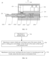
- an embodiment of this application provides an installation method of a braking apparatus.
- the method includes:
- the braking apparatus in this application has a simple structure. This greatly simplifies actual assembly complexity.
- the permanent magnet is disposed in a first piston of the master cylinder part, the master cylinder part is installed on the hydraulic block, and the travel sensor is fixed on the hydraulic block, so that assembly time is short, assembly efficiency is high, an assembly yield rate is high, and the costs are low. This is conducive to industrialization of the braking apparatus.
- Both the travel sensor and the first piston of the master cylinder part are directly disposed on the hydraulic block. This reduces the dimension chain between the travel sensor and the permanent magnet, and helps improve signal precision of the travel sensor.
- a control unit is manufactured, the control unit and the hydraulic block are disposed in a stacked manner, an opening of the first groove faces the control unit, the first groove communicates with an internal space of the control unit, and the travel sensor extends into the internal space of the control unit, to implement sealing of the travel sensor.
- the control unit is directly assembled and fixed with the hydraulic block through guide tooling, so that overall sealing and electric contact may be implemented.
- a part of the travel sensor extends into the first groove and is disposed adjacent to the permanent magnet, and the other part of the travel sensor extends into the internal space of the control unit and is configured to be electrically connected to a control substrate of the control unit.
- the hydraulic block and the control unit jointly perform a sealing function on the travel sensor, to prevent dust or water from an external environment from entering the travel sensor and affecting performance of the travel sensor.
- the travel sensor is always in a sealed environment formed by the hydraulic block and the control unit, and does not need to perform sealing protection (where for example, a side that is of a housing of the travel sensor and that faces the permanent magnet may be provided with an opening, and the housing does not completely isolate a sensing substrate and a sensing element from the outside), so that costs are reduced.
- the sensing substrate and the sensing element in the travel sensor do not need to be sealed for protection. This also reduces a volume of the travel sensor, saves an internal space of the braking apparatus, and further reduces a distance from the travel sensor to the permanent magnet.
- the dimension chain between the permanent magnet and the travel sensor is reduced through a reasonable layout of the permanent magnet and the travel sensor. This helps improve signal precision of the travel sensor.
- the travel sensor is disposed close to the permanent magnet, to reduce a gap between the permanent magnet and the travel sensor as much as possible. This effectively improves signal precision of the travel sensor.
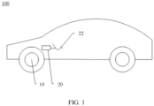
- FIG. 1 is a schematic diagram of a possible structure of a vehicle 100 according to an embodiment of this application
- FIG. 2 is a schematic diagram of a possible structure of a braking system 20 inside the vehicle 100
- the vehicle 100 may be a gasoline vehicle or an electric vehicle, for example, a pure electric vehicle, an extended-range electric vehicle, a hybrid electric vehicle, a fuel cell vehicle, or a new energy vehicle. This is not limited in this application.
- the vehicle 100 includes a wheel 10 and a braking system 20.
- the braking system 20 controls movement of the wheel 10 to implement braking of the vehicle 100.
- the braking system 20 includes an oil can 21, a brake pedal 22, a braking apparatus 23, a wheel braking loop 24, and a wheel brake 25.
- the oil can 21 is connected to a pipeline in the braking apparatus 23, the brake pedal 22 is connected to a push rod of the braking apparatus 23, and the wheel braking loop 24 is connected to a hydraulic block of the braking apparatus 23 and the wheel brake 25.
- the wheel brake 25 acts on the wheel 10.
- the oil can 21 provides a brake fluid to the braking apparatus 23.
- the braking apparatus 23 starts to work.
- the wheel braking loop 24 supplies a brake fluid with precise hydraulic pressure to the wheel brake 25 under joint modulation of the hydraulic block and a control unit of the braking apparatus 23.
- the wheel brake 25 controls movement of the wheel 10 to implement braking of the vehicle 100, and finally control a speed of the vehicle 100.
- the wheel brake may be a disc brake, a drum brake, or the like. This is not limited in this application.
- the braking apparatus 23 in embodiments of this application not only may be applied to the braking system 20 shown in FIG. 2 , but also may be applied to another electro-hydraulic braking system.
- a travel sensor of the braking apparatus 23 may alternatively be applied to another linear travel detection field.
- FIG. 3 is a schematic diagram of a possible structure of the braking apparatus 23
- FIG. 4 is a top view of the braking apparatus 23 shown in FIG. 3
- FIG. 5 is a sectional view of the braking apparatus 23 shown in FIG. 4 along A-A.
- the braking apparatus 23 includes a hydraulic block 231, a master cylinder part 232, and a travel sensor 233.
- the hydraulic block 231 is configured to accommodate a brake fluid.
- the hydraulic block 231 is internally provided with a pipeline (not shown in FIG. 3 ), and there is the brake fluid in the pipeline.
- the master cylinder part 232 is installed on the hydraulic block 231, and the travel sensor 233 is installed on the hydraulic block 231.
- the master cylinder part 232 includes a push rod 2323, a first piston 2321, a first elastic component 2325, a second piston 2327, and a second elastic component 2326.
- the master cylinder part 232 is configured to compress the brake fluid, so that the brake fluid obtains precise hydraulic pressure.
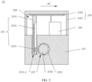
- FIG. 6 is a sectional view of the braking apparatus 23 shown in FIG. 4 along B-B.
- the hydraulic block 231 is provided with a first groove 2311-1 and a second groove 2311-2.
- the travel sensor 233 is located in the first groove 2311-1 and is fixedly connected to the hydraulic block 231.
- a fixing manner between the travel sensor 233 and the hydraulic block 231 may be fixing through a screw, fixing through a snap, fixing through interference fit, or fixing through crimping, or the like. This is not limited in this application.
- the second groove 2311-2 extends in a first direction A1, and the master cylinder part 232 is located in the second groove 2311-2 and is in sliding contact with the second groove 2311-2.
- the master cylinder part 232 is slidingly connected to the hydraulic block 231.
- the sliding connection herein means that the master cylinder part 232 can move back and forth in the first direction A1.
- the first groove 2311-1 and the second groove 2311-2 are sealed and isolated, that is, a space of the first groove 2311-1 does not communicate with a space of the second groove 2311-2, to prevent the brake fluid in the second groove 2311-2 from flowing to the first groove 2311-1, and affecting performance of the braking apparatus 23.
- shapes of the first groove 2311-1 and the second groove 2311-2 are not limited, and the first groove 2311-1 and the second groove 2311-2 may be circles, squares, or other shapes.
- the master cylinder part 232 includes the first piston 2321, and the first piston 2321 is located in the second groove 2311-2 and is slidingly connected to the hydraulic block 231.
- the first piston 2321 is internally provided with a permanent magnet 2322, that is, the master cylinder part 232 is internally provided with the permanent magnet 2322.
- the first piston 2321 may move back and forth in the first direction A1, and the permanent magnet 2322 may move back and forth in the first direction A1 with the first piston 2321.
- the permanent magnet 2322 and the first piston 2321 remain relatively static.
- the travel sensor 233 is disposed on a periphery of the permanent magnet 2322, and the travel sensor 233 and the first groove 2311-1 are disposed close to the permanent magnet 2322.
- disposing the travel sensor 233 close to the permanent magnet 2322 can improve precision of travel measurement, and help control a braking system more precisely.
- the travel sensor 233 is disposed outside the permanent magnet 2322 and does not communicate with the permanent magnet 2322, so that a risk of contacting the brake fluid by the travel sensor 233 can be reduced, normal working of the travel sensor 233 can be ensured, and a service life can be extended.
- the hydraulic block 231 is provided with the pipeline (not shown in FIG. 3 ), and there is the brake fluid in the pipeline.
- the pipeline is configured to transmit the brake fluid.
- the master cylinder part 232 is connected to the brake pedal 22.
- An operation force applied at the brake pedal 22 is transferred to the brake fluid in the hydraulic block 231 through the master cylinder part 232.
- the travel sensor 233 is configured to detect a movement amount of the permanent magnet 2322 to determine a movement amount of the first piston 2321, that is, is configured to: detect a travel of the permanent magnet 2322 and the first piston 2321 relative to the hydraulic block 231, output an electrical signal, and finally drive a brake unit, to implement precise control of a speed of the vehicle 100.
- signal precision of the travel sensor 233 is improved through a reasonable layout of the permanent magnet 2322 and the travel sensor 233.
- the permanent magnet 2322 is disposed inside the first piston 2321, and there is no need to dispose, on the hydraulic block 231, a hole part for installing the permanent magnet 2322. This simplifies a structure and an assembly process of the hydraulic block 231, provides more spaces for arranging the pipeline in the hydraulic block 231, and further reduces a dimension chain between the permanent magnet 2322 and the travel sensor 233.
- the dimension chain between the permanent magnet 2322 and the travel sensor 233 herein may be understood as tolerance accumulation between the permanent magnet 2322 and the travel sensor 233.
- the travel sensor 233 is installed in the first groove 2311-1, located on one side of the master cylinder part 232, and disposed close to the permanent magnet 2322.
- the travel sensor 233 may be directly fixed on the hydraulic block 231. In this disposing manner, the dimension chain between the travel sensor 233 and the permanent magnet 2322 is reduced. This helps improve precision of travel measurement performed by the travel sensor 233.
- the travel sensor 233 is disposed close to the permanent magnet 2322, to reduce a gap between the permanent magnet 2322 and the travel sensor 233 as much as possible. This effectively improves signal precision of the travel sensor 233.
- a second direction A2 is perpendicular to the first direction A1, the second direction A2 is also an arrangement direction of the master cylinder part 232 and the travel sensor 233, and the permanent magnet 2322 moves back and forth between a first position 2371 and a second position 2372.
- that the permanent magnet 2322 moves back and forth between a first position 2371 and a second position 2372 may be understood as: When the brake pedal is not stepped on, the first elastic component 2325 is in a natural state, and in this case, the permanent magnet 2322 is located at a leftmost end 2371 shown in FIG. 6 .
- the permanent magnet 2322 When the braking pedal is stepped on to a maximum travel, that is, when a compression amount of the first elastic component 2325 is maximum, the permanent magnet 2322 is located at a rightmost end 2372 shown in FIG. 6 .
- Vertical projection of a central position 2373 between the first position 2371 and the second position 2372 in the second direction A2 is located on the travel sensor 233. This helps improve precision of travel measurement, and simplifies a calibration process. It should be noted that the projection of the central position 2373 may not be located on the travel sensor 233, which may be determined based on an actual design requirement.
- the first position 2371, the second position 2372, and the central position 2373 may be understood as a point, or may be understood as a line.
- the travel sensor 233 directly faces the central position 2373 in the second direction A2. That is, the first position 2371 and the second position 2372 are symmetrical with respect to the travel sensor 233. Directly facing may be understood as that a connection line between the central position 2373 and a point on the travel sensor 233 is parallel to the second direction A2.
- the central position 2373 is set to be vertically projected on the travel sensor 233 in the second direction A2, so that a distance between the permanent magnet 2322 and the travel sensor 233 is not excessively large when the permanent magnet 2322 moves back and forth. In this way, the travel sensor 233 can detect sufficient magnetic field strength. This helps improve signal precision of the travel sensor 233.
- the vertical projection of the central position 2373 in the second direction A2 may alternatively not be on the travel sensor 233, that is, the first position 2371 and the second position 2372 are asymmetric with respect to the travel sensor 233. In this way, signal precision of the travel sensor 233 can be ensured provided that a travel interval with high magnetic field strength is selected.
- the travel sensor 233 includes a housing 2331, a sensing substrate 2332, and a sensing element 2333.
- the sensing substrate 2332 is fixed inside the housing 2331
- the sensing element 2333 is fixed on the sensing substrate 2332 and is electrically connected to the sensing substrate 2332
- the sensing element 2333 is located on a side that is of the sensing substrate 2332 and that is close to the master cylinder part 232.
- the sensing element 2333 may be electrically connected to the sensing substrate 2332 in a tin soldering manner.
- a part of the housing 2331 extends into the first groove 2311-1 and is fixed on the hydraulic block 231.
- the sensing element 2333 is located in the first groove 2311-1 and is disposed close to the permanent magnet 2322.
- a distance between the sensing element 2333 and the permanent magnet 2322 is less than a threshold.
- the distance between the sensing element 2333 and the permanent magnet 2322 is less than 10 mm.
- the sensing element 2333 can sense a magnetic field with specific magnetic induction strength, and can meet a requirement for sealing and isolation.
- the distance between the sensing element 2333 and the permanent magnet 2322 may be 8 mm, which may be specifically obtained through an experiment or simulation. Simulation is used as an example.
- the distance between the sensing element and the permanent magnet is related to a dimension of the first piston, a distance between the first groove and the second groove, and the like.
- the distance between the first groove 2311-1 and the second groove 2311-2 is controlled within a small enough range.
- the distance between the first groove 2311-1 and the second groove 2311-2 is greater than 1.5 mm and less than 2 mm, or the distance between the first groove 2311-1 and the second groove 2311-2 is less than 1.5 mm.
- the hydraulic block between the first groove 2311-1 and the second groove 2311-2 is excessively thin, and consequently the brake fluid leaks.
- the distance between the first groove 2311-1 and the second groove 2311-2 is greater than 2 mm.
- the magnetic induction strength, of the permanent magnet 2322, that can be detected by the travel sensor 233 is weak. That is, a distance between the travel sensor 233 and the master cylinder part 232 is controlled within a small enough range.
- the pipeline in the hydraulic block 231 is arranged in the hydraulic block 231 to avoid an area between the first groove 2311-1 and the second groove 2311-2, that is, the pipeline in the hydraulic block 231 is not disposed between the first groove 2311-1 and the second groove 2311-2.
- the pipeline may be arranged on two sides of the travel sensor 233 instead of being arranged in an area corresponding to the travel sensor 233.
- a gap between the first groove 2311-1 and the second groove 2311-2 is small, and no pipeline or other structure is disposed. In this way, it can be ensured that a distance between the travel sensor 233 and the permanent magnet 2322 is small.
- the hydraulic block between the first groove and the second groove meet a minimum requirement for sealing and isolation, to ensure that the distance between the travel sensor and the permanent magnet is as small as possible.
- the sensing element 2333 may be a Hall element, or may be another element.
- the first piston 2321 and the permanent magnet 2322 inside the first piston 2321 move back and forth, and a magnetic field at the sensing element 2333 changes.
- the sensing element 2333 obtains a movement amount of the permanent magnet 2322 based on the change of the magnetic field, determines a movement amount of the first piston 2321, and transmits the movement amount to a control unit in a form of an electrical signal. If the distance between the sensing element 2333 and the permanent magnet 2322 is excessively large, the magnetic field strength at the sensing element 2333 is weak.
- the sensing element 2333 is disposed close to the permanent magnet 2322. This helps ensure signal precision of the travel sensor 233.
- the braking apparatus 23 is provided with a control unit 234, the control unit 234 includes a housing 2341 and a control substrate 2342, and the control substrate 2342 is fixed inside the housing 2341.
- the control unit 234 and the hydraulic block 231 are disposed in a stacked manner, and the control unit 234 is fixed on the hydraulic block 231.
- a fixing manner between the control unit 234 and the hydraulic block 231 may be fixing through a screw, fixing through a bolt, or the like.
- a specific connection structure is not shown. This is not limited in this application.
- control unit 234 and the hydraulic block 231 are connected in a sealed manner, that is, the travel sensor 233 is not affected by dust, water vapor, or the like outside the braking apparatus in a sealed space of a travel between the control unit 234 and the hydraulic block 231.
- An opening of the first groove 2311-1 faces the control unit 234, the first groove 2311-1 communicates with an internal space of the control unit 234, and the travel sensor 233 extends into the internal space of the control unit 234, to implement sealing of the travel sensor 233.
- a part of the travel sensor 233 extends into the first groove 2311-1 and is disposed adjacent to the permanent magnet 2322, and the other part of the travel sensor 233 extends into the internal space of the control unit 234 and is configured to be electrically connected to the control substrate 2342.
- the hydraulic block 231 and the control unit 234 form a closed accommodation space 238, and the travel sensor 233 is located in the accommodation space 238.
- the hydraulic block 231 and the control unit 234 jointly perform a sealing function on the travel sensor 233, to prevent dust or water from an external environment from entering the travel sensor 233, and affecting performance of the travel sensor 233.
- the travel sensor 233 is always in a sealed environment formed by the hydraulic block 231 and the control unit 234, and does not need to perform sealing protection (where for example, a side that is of the housing 2331 of the travel sensor 233 and that faces the master cylinder part 232 may be provided with an opening, and the housing 2311-1 does not completely isolate the sensing substrate 2332 and the sensing element 2333 from the outside, but performs a sealing protection function on the sensing substrate 2332 and the sensing element 2333 through the hydraulic block 231 and the control unit 234), so that costs are reduced.
- the sensing substrate 2332 and the sensing element 2333 in the travel sensor 233 do not need to be sealed for protection. This also reduces a volume of the travel sensor 233, saves an internal space of the braking apparatus 23, and reduces the distance from the travel sensor 233 to the permanent magnet 2322.
- FIG. 7 is a schematic diagram of a structure of the braking apparatus 23.
- the braking apparatus 23 is provided with a sealing structure 235, and the sealing structure 235 is located between the control unit 234 and the hydraulic block 231, and is for the connection between the control unit 234 and the hydraulic block 231 in a sealed manner, so that the travel sensor 233 is located in the sealed environment formed by the control unit 234 and the hydraulic block 231, to prevent dust, water, or the like from an external environment from entering the travel sensor 233, and affecting performance of the travel sensor 233.
- the control unit 234 and the hydraulic block 231 are connected in a sealed manner, so that the travel sensor 233 is sealed, and the control unit 234 isolates the travel sensor 233 from the external environment. In this way, the travel sensor 233 is always in the sealed environment formed by the hydraulic block 231 and the control unit 234, and does not need to perform sealing protection, so that costs are reduced.
- the sealing structure 235 may be a sealing ring, and the sealing ring seals the hydraulic block 231 and the control unit 234 that are disposed in a stacked manner, so that a strict waterproof and dustproof level may be achieved, thereby helping protect a structure inside the control unit 234 and the travel sensor 233.
- the sealing structure 235 may alternatively be rubber, and sealing between the hydraulic block 231 and the control unit 234 may be implemented by coating rubber.
- the travel sensor 233 and the control unit 234 are of a split structure, the travel sensor 233 is directly fixed on the hydraulic block 231, and the control unit 234 is also directly fixed on the hydraulic block 231, so that a quantity of dimension chains between the travel sensor 233 and the control substrate 2342 of the control unit 234 is small and the dimension chain is easy to assemble.
- An electrical connection between the travel sensor 233 and the control substrate 2342 can implement good electrical contact by using control of a component dimension and an assembly process, and there is a sufficient design dimension margin for the electrical contact (which may be understood as that a contact area of the electrical connection between the travel sensor 233 and the control substrate 2342 may be designed to be small, to implement a good electrical connection; or a contact area remains unchanged, and a good electrical connection can be implemented even if there is some misplacement). In this way, requirements on the component size and the assembly process may be reduced, thereby helping reduce costs and improve an assembly yield rate.
- the travel sensor 233 is directly fixed on the hydraulic block 231, so that a quantity of dimension chains between the travel sensor 233 and the permanent magnet 2322 is small. This helps improve signal precision of the travel sensor 233.
- the quantity of dimension chains between the travel sensor 233 and the permanent magnet 2322 is small, so that a processing process and time are reduced. This helps reduce the costs and also helps improve the assembly yield rate.
- the electrical connection between the travel sensor 233 and the control substrate 2342 may be a connector clip, spring contact, metal pad contact, or the like. This is not limited in this application.
- the master cylinder part 232 is further provided with the push rod 2323, the first elastic component 2325, the second elastic component 2326, and the second piston 2327.
- the first piston 2321 is internally provided with a first separator 2328, and the push rod 2323 extends into the first piston 2321.
- the push rod 2323 abuts against the first separator 2328 to push the first piston 2321 to move.
- the first separator 2328 and the first piston 2321 may be of an integrated structure, and the structure is simple, which avoids a process of assembling.
- the first separator 2328 and the first piston 2321 may alternatively be of a split structure. In the split structure, the first separator 2328 may be installed in the first piston 2321 through interference fit, and it is ensured that the first piston 2321 is isolated into two spaces that are not in communication.
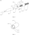
- FIG. 8 is a schematic exploded diagram of a partial structure of the master cylinder part 232.
- the braking apparatus 23 is provided with a structure sleeve 2324, the structure sleeve 2324 wraps the permanent magnet 2322, and the structure sleeve 2324 and the permanent magnet 2322 form a magnet assembly.
- both the structure sleeve 2324 and the permanent magnet 2322 are located inside the first piston 2321, and the structure sleeve 2324 and the first piston 2321 are in interference fit.
- Neither the structure sleeve 2324 nor the permanent magnet 2322 can move in the first piston 2321.
- the structure sleeve 2324 and the permanent magnet 2322 may move back and forth in the first direction A1 with the first piston 2321.
- the permanent magnet 2322 may be made of neodymium iron boron, or may be made of another material. There may be one or more permanent magnets 2322. In a case of a plurality of permanent magnets 2322, all the permanent magnets 2322 may be coaxially disposed in the structure sleeve 2324. In some possible implementations, the permanent magnet 2322 may be a cylinder, or may be a special-shaped structure such as a semi-cylinder.
- Some structures of the master cylinder part 232 are usually made of ferromagnetic materials, for example, the push rod 2323, the first elastic component 2325, and the second elastic component 2326.
- the first elastic component 2325 and the second elastic component 2326 cooperate with the permanent magnet 2322.
- the push rod 2323 cooperates with the first piston 2321, and is used for back-and-forth movement of the first piston 2321 and the permanent magnet 2322.
- the structures made of these ferromagnetic materials change a magnetic field of the permanent magnet 2322, affect a signal received by the travel sensor 233, and are not conducive to improving signal precision of the travel sensor 233.
- the structure sleeve 2324 may be disposed as being made of a non-ferromagnetic material (for example, may be made of plastic, aluminum, or the like), and the structure sleeve 2324 made of the non-ferromagnetic material wraps the permanent magnet 2322, that is, the permanent magnet 2322 is isolated from the ferromagnetic materials such as the push rod 2323, the first elastic component 2325, and the second elastic component 2326 by disposing the structure sleeve 2324, to avoid impact of the ferromagnetic materials such as the push rod 2323, the first elastic component 2325, and the second elastic component 2326 on the magnetic field of the permanent magnet 2322, and improve signal precision of the travel sensor 233.
- a non-ferromagnetic material for example, may be made of plastic, aluminum, or the like
- distances between the permanent magnet 2322 and the first elastic component 2325 and the second elastic component 2326 and a distance between the permanent magnet 2322 and the push rod 2323 may be set to be large. In this way, impact of the ferromagnetic materials such as the push rod 2323, the first elastic component 2325, and the second elastic component 2326 on the magnetic field of the permanent magnet 2322 may also be avoided.
- some gaskets made of non-ferromagnetic materials are disposed between the permanent magnet 2322 and the first elastic component 2325 and between the permanent magnet 2322 and the push rod 2323, to avoid impact of the ferromagnetic materials such as the push rod 2323, the first elastic component 2325, and the second elastic component 2326 on the magnetic field of the permanent magnet 2322. This helps improve signal precision of the travel sensor 233.
- the structure sleeve 2324 includes a main body part 2324-1 and a guiding part 2324-2.
- the main body part 2324-1 wraps the permanent magnet 2322, that is, the permanent magnet 2322 is located in the main body part 2324-1.
- the main body part 2324-1 includes a body 2324-3 and a limiting part 2324-4.
- the limiting part 2324-4 is encircled around an outer wall of the body 2324-3, the limiting part 2324-4 does not completely cover the body 2324-3, and the limiting part 2324-4 is disposed close to the guiding part 2324-2.
- the structure sleeve 2324 is provided with an anti-rotation groove 2324-5.
- the anti-rotation groove 2324-5 may be disposed on the limiting part 2324-4.
- an end face dimension of the guiding part 2324-2 may be set to be less than an end face dimension of the main body part 2324-1.
- the main body part 2324-1 and the guiding part 2324-2 are cylinders, and a diameter of the main body part 2324-1 is greater than a diameter of the guiding part 2324-2.
- one end of the first elastic component 2325 is sleeved on the guiding part 2324-2 and abuts against one end of the main body part 2324-1, and the guiding part 2324-2 with a small dimension is configured to guide and constrain assembly of the first elastic component 2325. This helps avoid a problem such as deflection or sliding of the first elastic component 2325 in a back-and-forth movement process of the first piston 2321.
- the push rod 2323 acts on the first piston 2321, one end of the first elastic component 2325 is sleeved on the guiding part 2324-2 and abuts against the main body part 2324-1 to act on the magnet assembly, the first piston 2321 and the magnet assembly (the permanent magnet 2322 and the structure sleeve 2324) move back and forth under a joint action of the push rod 2323, the first elastic component 2325, and the second elastic component 2326, and the travel sensor 233 detects that the movement is transmitted to the control unit 234 in a form of an electrical signal.
- an operation force applied at the brake pedal 22 is transmitted to the push rod 2323, the push rod 2323 acts on the first separator 2328 and pushes the first piston 2321 to move, the first elastic component 2325 and the second elastic component 2326 are compressed, and apply an elastic force at the magnet assembly, and a direction in which the force is applied by the first elastic component 2325 and the second elastic component 2326 at the magnet assembly is opposite to that in which a force is applied by the push rod 2323 at the first piston 2321. Therefore, the first piston 2321 and the magnet assembly move back and forth under a joint action of the first elastic component 2325, the second elastic component 2326, and the push rod 2323.
- both ends of the second groove 2311-2 are in an open state.
- the second groove 2311-2 is provided with an open end 2311-3 and a limiting end 2311-4, and both the open end 2311-3 and the limiting end 2311-4 are in an open state.
- the second groove 2311-2 is a through hole
- the first piston 2321 is installed on the hydraulic block 231 from the open end 2311-3
- the limiting end 2311-4 is provided with a limiting structure to limit a position of the second elastic component 2326, to prevent the second elastic component 2326 from being detached from the second groove 2311-2.
- the limiting structure may be a baffle (not shown in FIG.
- the baffle is located at the limiting end 2311-4, and the second elastic component 2326 abuts against the baffle.
- the limiting structure may alternatively be in another form. This is not limited in this application.
- the second groove 2311-2 is a through hole. In this way, a part of the second elastic component 2326 may extend out of the second groove 2311-2, provided that the second elastic component 2326 can abut against the limiting structure of the limiting end 2311-4. This helps reduce a dimension of the hydraulic block, and facilitates miniaturization of the braking apparatus.
- the second groove 2311-2 may alternatively be a blind hole, and the second elastic component 2326 abuts against a right end of the second groove 2311-2, so that a structure of the hydraulic block is simplified, installation is simple, and there is no need to separately dispose the limiting structure for limiting the second elastic component 2326.
- FIG. 9 is a schematic diagram of a structure of the first piston 2321.
- An inner wall of the first piston 2321 includes a first area 2321-1 and a second area 2321-2, and an inner diameter of the first area 2321-1 is less than an inner diameter of the second area 2321-2.
- the body 2324-3 of the structure sleeve 2324 is disposed in correspondence with the first area 2321-1, the limiting part 2324-4 and the guiding part 2324-2 of the structure sleeve 2324 are disposed in correspondence with the second area 2321-2, and one end of the limiting part 2324-4 away from the guiding part 2324-2 abuts against an end part of the first area 2321-1.
- the permanent magnet 2322 usually forms the magnet assembly with the structure sleeve 2324 in a form of injection molding, interference fit, or the like. In this way, when the magnet assembly is installed inside the first piston 2321, the limiting part 2324-4 abuts against the end part of the first area 2321-1 to limit a position of the magnet assembly in the first piston 2321, so that the magnet assembly is installed to a preset position, to prevent a problem caused when the magnet assembly is installed in a misplaced manner. For example, the misplaced installation of the permanent magnet causes an increase in the distance between the travel sensor 233 and the permanent magnet 2322, affects the magnetic field at the travel sensor 233, and is not conducive to improving signal precision of the travel sensor 233.
- the braking apparatus 23 is provided with an anti-rotation mechanism 26, and the anti-rotation mechanism 26 is configured to prevent the permanent magnet 2322 from rotating in a circumferential direction of the permanent magnet 2322.
- the anti-rotation mechanism 26 includes an anti-rotation groove 2324-5 and an anti-rotation rib 2321-3, and the anti-rotation rib 2321-3 is located on an inner wall of the first piston 2321.
- the anti-rotation rib 2321-3 is clamped into the anti-rotation groove 2324-5 of the structure sleeve 2324, to prevent the structure sleeve 2324 from rotating in a circumferential direction of the structure sleeve 2324 in the first piston 2321, that is, prevent the permanent magnet 2322 and the structure sleeve 2324 from rotating in the circumferential directions of the permanent magnet 2322 and the structure sleeve 2324 in the first piston 2321.
- the sensing element 2333 of the travel sensor 233 determines a linear travel position of the permanent magnet 2322 based on a sensed magnetic field angle change.
- the permanent magnet 2322 in a process of magnetizing, the permanent magnet 2322 inevitably has a magnetic deflection angle relative to an axis, which is generally within 5°. If the permanent magnet 2322 moves linearly relative to the sensing element 2333, and also rotates in the circumferential direction, consistency between a magnetic deflection angle of the travel sensor 233 and a magnetic deflection angle in a calibration state is changed, thereby affecting signal precision of the travel sensor 233.
- both the permanent magnet 2322 and the structure sleeve 2324 are coaxially disposed with the first piston 2321.
- the anti-rotation rib 2321-3 is clamped into the anti-rotation groove 2324-5, to prevent the structure sleeve 2324 from rotating in the circumferential direction of the structure sleeve 2324 in the first piston 2321, that is, prevent the permanent magnet 2322 from rotating in the circumferential direction of the permanent magnet 2322 in the first piston 2321.
- This helps improve measurement precision, and ensures consistency of measurement precision in a plurality of times of back-and-forth movement.
- a structure in which the anti-rotation groove 2324-5 and the anti-rotation rib 2321-3 cooperate is disposed, so that in a process of installing the structure sleeve 2324 on the first piston 2321, initial positioning and installation can be implemented provided that the anti-rotation rib 2321-3 is clamped in the anti-rotation groove 2324-5, to improve installation efficiency. In addition, a travel measurement error caused by uneven magnetization of the permanent magnet can also be avoided.
- the anti-rotation rib 2321-3 and the anti-rotation groove 2324-5 are merely an implementation of preventing the magnet assembly from rotating in a circumferential direction of the magnet assembly in the first piston 2321, and there is another design structure of a combination of the anti-rotation rib and the anti-rotation groove.
- an anti-rotation design form such as interference fit, a snap, crimping, and glue filling may alternatively be used.
- the permanent magnet 2322 is usually fixed with the structure sleeve 2324 in a form of inj ection molding, interference fit, or the like, to ensure that the permanent magnet 2322 does not rotate relative to a ground axis in the structure sleeve 2324.
- the first piston 2321 and the hydraulic block 231 also have a similar anti-rotation structure directly or indirectly.
- the magnetic deflection angle of the permanent magnet 2322 is always consistent with that of the sensing element 2333, that is, ensure precision consistency of the travel sensor 233.
- the structure sleeve 2324 and the first piston 2321 may be noncoaxially disposed, and the structure sleeve 2324 is disposed on one side of the travel sensor 233.
- the permanent magnet 2322 and the structure sleeve 2324 may be noncoaxially disposed, and the permanent magnet 2322 is disposed on one side of the travel sensor 233. In this way, the distance from the permanent magnet 2322 to the travel sensor 233 is reduced, and signal precision of the travel sensor 233 is improved.
- first pistons there are two first pistons in this implementation.
- One is the first piston 2321, and the other is the second piston 2327.
- the second piston 2327 is internally provided with a second separator 2327-1.
- the first elastic component 2325 is located on a side that is of the second separator 2327-1 and that is close to the first piston 2321.
- the second elastic component 2326 is located on a side that is of the second separator 2327-1 and that is away from the first piston 2321.
- the second separator 2327-1 and the second piston 2327 may be of an integrated structure, and the structure is simple, which avoids a process of assembling.
- the second separator 2327-1 and the second piston 2327 may alternatively be of a split structure.
- the second separator 2327-1 may be installed in the second piston 2327 through interference fit, and it is ensured that the second piston 2327 is isolated into two spaces that are not in communication.
- a booster unit (not shown in FIG. 6 and FIG. 8 ) of the braking apparatus works normally, a liquid outlet on the hydraulic block 231 corresponding to the second elastic component 2326 is closed, and the brake fluid is filled between the second elastic component 2326 and the hydraulic block 231 and cannot be discharged. Therefore, the second elastic component 2326 cannot be compressed, only the first elastic component 2325 is compressed, and the booster unit of the braking apparatus and the first elastic component 2325 jointly provide power for back-and-forth movement of the first piston 2321.
- the liquid outlet on the hydraulic block 231 corresponding to the second elastic component 2326 is opened, and both the first elastic component 2325 and the second elastic component 2326 are compressed.
- Design of the two elastic components namely, the first elastic component 2325 and the second elastic component 2326, increases reliability of the braking apparatus 23, and the second piston 2327 limits the first elastic component 2325 and the second elastic component 2326.
- the first elastic component 2325 and the second elastic component 2326 may be springs, or may be other elastic apparatuses. This is not limited in this application.
- the braking apparatus 23 is provided with a solenoid valve 236, the solenoid valve 236 is located in the control unit 234 and is fixed on the top of the hydraulic block 231, the solenoid valve 236 is electrically connected to the control substrate 2342 of the control unit 234, and the solenoid valve 236 is disposed away from the travel sensor 233.
- the solenoid valve 236 is configured to control opening and closing of the pipelines inside the hydraulic block 231. However, when the solenoid valve 236 works, a strong electromagnetic field is generated, and magnetic leakage interferes with a magnetic field signal transmitted by the permanent magnet 2322 to the sensing element 2333.
- a value of a safety distance is set based on a straight-line distance from the solenoid valve 236 to the sensing element 2333.
- the value of the safety distance may be obtained through magnetic leakage simulation analysis of the solenoid valve 236 and precision simulation analysis of the sensing element 2333.
- the value of the safety distance may alternatively be obtained through an experiment or a combination of an experiment and simulation.
- the solenoid valve 236 needs to be disposed away from the sensing element 2333 of the travel sensor 233, and is specifically disposed as required.
- the independent travel sensor 233 is disposed on one side of the master cylinder part 232 and is disposed adjacent to the master cylinder part 232.
- the travel sensor 233 may be disposed on any side of the master cylinder part 232 as required.
- the travel sensor 233 and the master cylinder part 232 are arranged in a direction perpendicular to that in which the hydraulic block 231 and the control unit 234 are stacked.
- the travel sensor 233 is disposed on one side of the master cylinder part 232 in a direction perpendicular to that in which the hydraulic block 231 and the control unit 234 are stacked. This simplifies a structure of the travel sensor 233.
- the first groove 2311-1 may be a deep groove, and the sensing element 2333 of the travel sensor 233 is deep into the first groove 2311-1, and is not vulnerable to impact of magnetic leakage of the solenoid valve 236 inside the control unit 234. This helps improve signal precision of the travel sensor 233.
- FIG. 10 is a schematic diagram of a structure of the braking apparatus 23 according to an embodiment of this application.
- the travel sensor 233 may be disposed on any side of the master cylinder part 232 as required, and the independent travel sensor 233 is disposed on one side of the master cylinder part 232 and is disposed adjacent to the master cylinder part 232.
- the first groove 2311-1 is located between the master cylinder part 232 and the control unit 234.
- the travel sensor 233 is located on a side that is of the master cylinder part 232 that is close to the control unit 234.
- the first groove 2311-1 is located between the master cylinder part 232 and the control unit 234. In this way, the first groove 2311-1 is a shallow groove. This helps improve feasibility of more reasonable layout for pipelines arranged vertically and horizontally inside the hydraulic block 231, has less interference with pipeline arrangement inside the hydraulic block 231, and facilitates miniaturization and processing convenience of the braking apparatus 23.
- FIG. 11 is a top view of the braking apparatus 23 shown in FIG. 10
- FIG. 12 is a sectional view of the braking apparatus 23 shown in FIG. 11 along C-C
- FIG. 13 is a sectional view of the braking apparatus 23 shown in FIG. 11 along D-D.
- the housing 2331 of the travel sensor 233 includes a connecting part 2331-1 and a mounting part 2331-2.
- the connecting part 2331-1 and the mounting part 2331-2 are disposed in an included angle.
- the mounting part 2331-2 is located in the first groove 2311-1 and is fixedly connected to the hydraulic block 231.
- the sensing element 2333 and the sensing substrate 2332 are located in the mounting part 2331-2.
- One end of the connecting part 2331-1 is connected to the mounting part 2331-2, and the other end of the connecting part 2331-1 extends into the control unit 234.
- the included angle between the connecting part 2331-1 and the mounting part 2331-2 may be 90°
- the connecting part 2331-1 and the mounting part 2331-2 may be of an L-shaped structure. Disposing of the connecting part 2331-1 and the mounting part 2331-2 of the L-shaped structure helps implement disposing of the sensing element 2333 close to the permanent magnet 2322, improve travel detection precision, and implement an electrical connection between the sensing substrate 2332 and the control substrate 2342.
- the housing 2332 of the travel sensor 233 may be designed as an L-shaped structure, that is, the connecting part 2331-1 and the mounting part 2331-2 form an L-shaped structure.
- the electrical connection between the travel sensor 233 and the control substrate 2342 may be a connector clip, spring contact, metal pad contact, or the like. This is not limited in this application.
- the travel sensor 233 may alternatively be disposed on another side of the master cylinder part 232.
- a shape and a depth of the first groove 2311-1 are not limited to those shown in FIG. 5 and FIG. 12 , and the first groove may alternatively be disposed in an inclined manner. This is not limited in this application.
- the braking apparatus 23 provided in this implementation of this application has a simple structure. This greatly simplifies assembly difficulty of the braking apparatus 23.
- An implementation of this application provides an installation method of the braking apparatus 23. As shown in FIG. 14 , an installation method of the braking apparatus 23 according to an implementation includes the following steps: T10: Manufacture the hydraulic block 231.
- the hydraulic block 231 is provided with the first groove 2311-1 and the second groove 2311-2, the first groove 2311-1 is disposed close to the second groove 2311-2, and the second groove 2311-2 extends in the first direction A1.
- T20 Manufacture the master cylinder part 232, and dispose a part of the master cylinder part 232 in the second groove 2311-2 and slidingly connect the part of the master cylinder part 232 to the hydraulic block 231.
- the master cylinder part 232 includes the first piston 2321.
- the first piston 2321 is disposed in the second groove 2311-2 and is slidingly connected to the hydraulic block 231.
- the first piston 2321 is internally provided with the permanent magnet 2322, that is, the master cylinder part 232 is provided with the permanent magnet 2322.
- the first piston 2321 may move back and forth in the first direction A1, and the permanent magnet 2322 may move back and forth in the first direction A1 with the first piston 2321.
- the permanent magnet 2322 and the first piston 2321 remain relatively static.
- T30 Manufacture the travel sensor 233, and dispose the travel sensor 233 in the first groove 2311-1 and fixedly connect the travel sensor 233 to the hydraulic block 231.
- the travel sensor 233 is disposed on a periphery of the permanent magnet 2322, and the travel sensor 233 and the first groove 2311-1 are disposed close to the permanent magnet 2322.
- the travel sensor 233 is configured to detect a movement amount of the permanent magnet 2322, to determine a movement amount of the first piston 2321.
- the braking apparatus 23 in this application has a simple structure. This greatly simplifies actual assembly complexity.
- the permanent magnet 2322 is disposed in the first piston of the master cylinder part 232, the master cylinder part 232 is installed on the hydraulic block 231, and the travel sensor 233 is fixed on the hydraulic block 231, so that time is short, assembly efficiency is high, an assembly yield rate is high, and costs are low. This is conducive to industrialization of the braking apparatus 23.
- the travel sensor 233 is directly fixed on the hydraulic block 231. This reduces the dimension chain between the travel sensor 233 and the permanent magnet 2322, and helps improve signal precision of the travel sensor 233.
- the installation method of the braking apparatus 23 further includes: manufacturing the control unit 234, disposing the control unit 234 and the hydraulic block 231 in a stacked manner, and fixing the control unit 234 to the hydraulic block 231.
- the braking apparatus 23 includes the control unit 234, and an opening of the first groove 2311-1 faces the control unit 234.
- the control unit 234 and the hydraulic block 231 are disposed in a stacked manner, the first groove 2311-1 communicates with internal space of the control unit 234, and the travel sensor 233 extends into the internal space of the control unit 234, to implement sealing of the travel sensor 233.
- the control unit 234 may be assembled and fixed with the hydraulic block 231 through guide tooling.
- a part of the travel sensor 233 extends into the first groove 2311-1 and is disposed adjacent to the permanent magnet 2322, and the other part of the travel sensor 233 extends into the internal space of the control unit 234 and is configured to be electrically connected to the control substrate 2342.
- the hydraulic block 231 and the control unit 234 jointly perform a sealing function on the travel sensor 233, to prevent dust or water from an external environment from entering the travel sensor 233 and affecting performance of the travel sensor 233.
- the travel sensor 233 is always in a sealed environment formed by the hydraulic block 231 and the control unit 234, and does not need to perform sealing protection (where for example, a side that is of the housing 2331 of the travel sensor 233 and that faces the master cylinder part 232 may be provided with an opening, and the housing 2311-1 does not completely isolate the sensing substrate 2332 and the sensing element 2333 from the outside), so that costs are reduced.
- the sensing substrate 2332 and the sensing element 2333 in the travel sensor 233 do not need to be sealed for protection. This also reduces a volume of the travel sensor 233, and saves an internal space of the braking apparatus 23.
- the master cylinder part 232 may be first installed on the hydraulic block 231, then the travel sensor 233 is installed on the hydraulic block 231, and then the control unit 234 is installed on the hydraulic block 231.
- the travel sensor 233 may be first installed on the hydraulic block 231, then the master cylinder part 232 is installed on the hydraulic block 231, and then the control unit 234 is installed on the hydraulic block 231.
- the travel sensor 233 may be first installed on the hydraulic block 231, then the control unit 234 is installed on the hydraulic block 231, and then the master cylinder part 232 is installed on the hydraulic block 231. This is not limited in this application.
- the dimension chain between the permanent magnet 2322 and the travel sensor 233 is reduced through a reasonable layout of the permanent magnet 2322 and the travel sensor 233. This helps improve signal precision of the travel sensor 233.
- the travel sensor 233 is disposed close to the permanent magnet 2322, to reduce a gap between the permanent magnet 2322 and the travel sensor 233 as much as possible. This effectively improves signal precision of the travel sensor 233.
Landscapes
- Engineering & Computer Science (AREA)
- Mechanical Engineering (AREA)
- Transportation (AREA)
- General Engineering & Computer Science (AREA)
- Regulating Braking Force (AREA)
- Transmission Of Braking Force In Braking Systems (AREA)
Abstract
Description
- The present invention relates to the field of vehicle technologies, and in particular, to a braking apparatus, a braking system, and a vehicle.
- A braking system of a vehicle is an important component of a vehicle safety control system. A main function of the braking system is to decelerate or even stop a traveling vehicle, or to keep a speed of a vehicle traveling downhill stable, or to keep a stopped vehicle from moving.
- The braking system includes a braking apparatus, and a travel sensor in the braking apparatus generally uses a magnetic induction principle. When a permanent magnet moves with a change of a pedal travel, a sensing element in the travel sensor detects a magnetic field change and converts the magnetic field change into an electrical signal. However, a distance (an air gap) between the permanent magnet and the sensing element has great impact on magnetic field strength at the travel sensor. A larger air gap is less conducive to ensuring signal precision of the travel sensor. In addition, a large quantity of dimension chains between the permanent magnet and the sensing element also affects quality control of a signal precision level of the travel sensor.
- Therefore, a layout design of the permanent magnet and the travel sensor is quite important to control of the signal precision of the travel sensor.
- Embodiments of this application provide a braking apparatus, a braking system, and a vehicle. A reasonable layout of a permanent magnet and a travel sensor in the braking apparatus is performed, so that a dimension chain between the permanent magnet and a sensing element in the travel sensor is reduced, a gap between the permanent magnet and the travel sensor is reduced, and signal precision of the travel sensor is effectively improved.
- According to a first aspect, an embodiment of this application provides a braking apparatus. The braking apparatus includes a hydraulic block, a master cylinder part, and a travel sensor. The hydraulic block is provided with a first groove and a second groove. The second groove extends in a first direction. The master cylinder part is located in the second groove and is in sliding contact with the second groove. The master cylinder part in the second groove moves back and forth in the first direction. The master cylinder part is internally provided with a permanent magnet. The travel sensor is located in the first groove and is fixedly connected to the hydraulic block, and is configured to detect a movement amount of the permanent magnet. Both the master cylinder part and the travel sensor are installed on the hydraulic block, the first groove is disposed close to the second groove, the travel sensor is located in the first groove, and the master cylinder part is located in the second groove. That is, the travel sensor is disposed close to the master cylinder part.
- The master cylinder part includes a first piston. The permanent magnet is disposed in the first piston. The first piston may move back and forth in an axial direction (namely, the first direction) of the first piston. The permanent magnet is located inside the first piston and may also move back and forth in the first direction with the first piston. The hydraulic block is internally provided with a pipeline. There is a brake fluid in the pipeline. The master cylinder part is connected to a brake pedal. An operation force applied at the brake pedal is transferred to the brake fluid in the hydraulic block through the master cylinder part. In a process of applying the operation force at the brake pedal, the travel sensor is configured to: detect a travel of the permanent magnet relative to the hydraulic block, output an electrical signal, and finally drive a brake unit, to implement precise control of a speed of a vehicle.
- In this application, signal precision of the travel sensor is improved through a reasonable layout of the permanent magnet and the travel sensor. The permanent magnet is disposed inside the master cylinder part, and there is no need to dispose, on the hydraulic block, a hole part for separately installing the permanent magnet. This simplifies a structure of the hydraulic block, provides more spaces for arranging the pipeline in the hydraulic block, and reduces a dimension chain between the permanent magnet and the travel sensor. The dimension chain between the permanent magnet and the travel sensor herein may be understood as tolerance accumulation between the permanent magnet and the travel sensor. This helps simplify an installation method of the braking apparatus, improves installation precision of the braking apparatus, and also improves precision of travel detection of the braking apparatus. The travel sensor is installed in the first groove, located on one side of the master cylinder part, and disposed close to the permanent magnet, that is, the travel sensor is directly fixed on the hydraulic block. This reduces the dimension chain between the travel sensor and the permanent magnet, and helps improve signal precision of the travel sensor. In the implementation of this application, the travel sensor is disposed close to the permanent magnet, to reduce a gap between the permanent magnet and the travel sensor as much as possible. This effectively improves signal precision of the travel sensor.
- In a possible implementation, the permanent magnet moves between a first position and a second position, a central position between the first position and the second position is vertically projected on the travel sensor in a second direction, and the second direction is perpendicular to the first direction. In other words, the travel sensor directly faces the central position between the first position and the second position in the second direction. That is, the first position and the second position are symmetrical with respect to the travel sensor. Directly facing may be understood as that a connection line between the central position and a point on the travel sensor is parallel to the second direction. In this implementation, the central position is set to be vertically projected on the travel sensor in the second direction, so that a distance between the permanent magnet and the travel sensor is not excessively large when the permanent magnet moves back and forth. In this way, the travel sensor can detect sufficient magnetic field strength. This helps improve precision of travel measurement, and simplifies a calibration process.
- In some other implementations, the vertical projection of the central position in the second direction may alternatively not be on the travel sensor, that is, the first position and the second position are asymmetric with respect to the travel sensor. In this way, signal precision of the travel sensor can be ensured provided that a travel interval with high magnetic field strength is selected.
- In a possible implementation, the travel sensor is provided with a sensing element, the sensing element is located in the first groove, and a distance between the sensing element and the permanent magnet is less than a threshold. For example, the distance between the sensing element and the permanent magnet is less than 10 mm. In this way, the sensing element can sense a magnetic field with specific magnetic induction strength, and can meet a requirement for sealing and isolation. For example, the distance between the sensing element and the permanent magnet may be 8 mm, which may be specifically obtained through an experiment or simulation. Simulation is used as an example. The distance between the sensing element and the permanent magnet is related to a dimension of the first piston, a distance between the first groove and the second groove, and the like. These pieces of data are input into a simulation model, so that magnetic induction strength, of the permanent magnet, that can be sensed by the sensing element and that is greater than 10 mT is obtained. The sensing element may be a Hall element, or may be another element. The sensing element obtains the movement amount of the permanent magnet based on a magnetic field change, and transmits the movement amount to a control unit in a form of an electrical signal. If the distance between the sensing element and the permanent magnet is excessively large, the magnetic field strength at the sensing element is weak. In this way, when a magnetic field changes, it is difficult for the sensing element to precisely sense a change amount of the magnetic field, and consequently signal precision of the travel sensor is affected. In this implementation, the sensing element is disposed in the first groove and close to the permanent magnet. This helps ensure signal precision of the travel sensor. That the sensing element is disposed close to the permanent magnet may be understood as that a gap between the sensing element and the permanent magnet is as small as possible in a case in which overall performance of the braking apparatus is ensured. Specifically, the gap may be disposed based on an actual situation. It should be noted that, disposing the travel sensor close to the permanent magnet can improve precision of travel measurement, and help control a braking system more precisely. However, the travel sensor is disposed outside the permanent magnet and does not communicate with the permanent magnet, so that a risk of contacting the brake fluid by the travel sensor can be reduced, normal working of the travel sensor can be ensured, and a service life can be extended.
- In a possible implementation, the hydraulic block is internally provided with a pipeline, the pipeline is configured to transmit a brake fluid, and the pipeline is arranged in the hydraulic block to avoid an area between the first groove and the second groove, so that a distance between the first groove and the second groove is controlled within a small enough range. That is, the pipeline is not disposed between the first groove and the second groove. In other words, a gap between the first groove and the second groove is small, and the pipeline cannot be disposed. In this way, it can be ensured that the distance between the travel sensor and the permanent magnet is small. This helps improve signal precision of the travel sensor, and also avoids impact of the pipeline on a signal received by the travel sensor.
- In a possible implementation, the first groove and the second groove are sealed and isolated, that is, a space of the first groove does not communicate with a space of the second groove, to prevent the brake fluid in the second groove from flowing to the first groove, and affecting performance of the braking apparatus. Wall thickness of the hydraulic block between the first groove and the second groove meets a minimum requirement for sealing and isolation, to ensure that the distance between the travel sensor and the permanent magnet is as small as possible.
- In a possible implementation, the travel sensor further includes a housing and a sensing substrate. The sensing substrate is fixed inside the housing, the sensing element is disposed on the sensing substrate, and the sensing element is electrically connected to the sensing substrate. The sensing element is located on a side that is of the sensing substrate and that is close to the master cylinder part, to ensure that a distance between the sensing element and the master cylinder part is as small as possible.
- In some possible implementations, a fixing manner between the travel sensor and the hydraulic block may be fixing through a screw, fixing through a snap, fixing through interference fit, or fixing through crimping, or the like. This is not limited in this application.
- In a possible implementation, the braking apparatus includes a control unit, the control unit and the hydraulic block are disposed in a stacked manner, an opening of the first groove faces the control unit, the first groove communicates with an internal space of the control unit, and the travel sensor extends into the internal space of the control unit, to implement sealing of the travel sensor. A part of the travel sensor extends into the first groove and is disposed adjacent to the permanent magnet, and the other part of the travel sensor extends into the internal space of the control unit and is configured to be electrically connected to a control substrate of the control unit. The hydraulic block and the control unit form an accommodation space, the travel sensor is located in the accommodation space, and the hydraulic block and the control unit jointly perform a sealing function on the travel sensor, to prevent dust or water from an external environment from entering the travel sensor, and affecting performance of the travel sensor. The travel sensor is always in a sealed environment formed by the hydraulic block and the control unit, and does not need to perform sealing protection (where for example, a side that is of the housing of the travel sensor and that faces the permanent magnet may be provided with an opening, and the housing does not completely isolate the sensing substrate and the sensing element from the outside), so that costs are reduced. In addition, the sensing substrate and the sensing element in the travel sensor do not need to be sealed for protection. This also reduces a volume of the travel sensor, saves an internal space of the braking apparatus, and further reduces the distance from the travel sensor to the permanent magnet.
- In a possible implementation, the braking apparatus is provided with a sealing structure, and the sealing structure is located between the control unit and the hydraulic block. The sealing structure may be a sealing ring, and the sealing ring seals between the hydraulic block and the control unit that are disposed in a stacked manner, so that a strict waterproof and dustproof level may be achieved, thereby helping protect a structure inside the control unit and the travel sensor. In some implementations, the sealing structure may alternatively be rubber, and sealing between the hydraulic block and the control unit may be implemented by coating rubber. The control unit and the hydraulic block are connected in a sealed manner, so that the travel sensor is sealed, and the control unit isolates the travel sensor from the external environment. In this way, the travel sensor is always in the sealed environment formed by the hydraulic block and the control unit, and does not need to perform sealing protection, so that costs are reduced.
- In a possible implementation, the travel sensor and the control unit are of a split structure. In an implementation of this application, the travel sensor is directly fixed on the hydraulic block, and the control unit is also directly fixed on the hydraulic block, so that a quantity of dimension chains between the travel sensor and the control substrate of the control unit is small and the dimension chain is easy to assemble. An electrical connection between the travel sensor and the control substrate of the control unit can implement good electrical contact by using control of a component dimension and an assembly process, and there is a sufficient design dimension margin for the electrical contact (which may be understood as that a contact area of the electrical connection between the travel sensor and the control substrate of the control unit may be designed to be small, to implement a good electrical connection; or a contact area remains unchanged, and a good electrical connection can be implemented even if there is some misplacement). In this way, requirements on the component dimension and the assembly process may be reduced, thereby helping reduce costs and improve an assembly yield rate. In addition, the travel sensor is directly fixed on the hydraulic block, so that a quantity of dimension chains between the travel sensor and the permanent magnet is small. This helps improve signal precision of the travel sensor. In addition, the quantity of dimension chains between the travel sensor and the permanent magnet is small, so that a processing process and time are reduced. This helps reduce the costs and also helps improve the assembly yield rate.
- In a possible implementation, the travel sensor and the master cylinder part are arranged in a direction perpendicular to that in which the hydraulic block and the control unit are stacked. The independent travel sensor is disposed on one side of the master cylinder part and is disposed adjacent to the master cylinder part, and the travel sensor may be disposed on any side of the master cylinder part as required. In this implementation, the travel sensor is disposed on one side of the master cylinder part in a direction perpendicular to that in which the hydraulic block and the control unit are stacked. This simplifies a structure of the travel sensor. The first groove is a deep groove, and the sensing element of the travel sensor is deep into the first groove, and is not vulnerable to impact of magnetic leakage of a solenoid valve inside the control unit. This helps improve signal precision of the travel sensor.
- In a possible implementation, the first groove is located between the master cylinder part and the control unit. In other words, the travel sensor is located on a side that is of the master cylinder part and that is close to the control unit, the independent travel sensor is disposed on one side of the master cylinder part and is disposed adjacent to the master cylinder part, and the travel sensor may be disposed on any side of the master cylinder part as required. In this implementation, the travel sensor is located on the side that is of the master cylinder part and that is close to the control unit, that is, the first groove is a shallow groove. This helps improve feasibility of more reasonable layouts for pipelines arranged vertically and horizontally inside the hydraulic block, has less interference with pipeline arrangement inside the hydraulic block, and facilitates miniaturization and processing convenience of the braking apparatus.
- In a possible implementation, the travel sensor is provided with a housing, the housing includes a mounting part and a connecting part, the mounting part is located in the first groove and is fixedly connected to the hydraulic block, the sensing element is located in the mounting part, one end of the connecting part is connected to the mounting part, and the other end of the connecting part extends into the control unit. The mounting part and the connecting part are disposed in an included angle. For example, the mounting part and the connecting part may be of an L-shaped structure, that is, an included angle between the mounting part and the connecting part is a right angle. Disposing the connecting part and the mounting part of the L-shaped structure helps implement disposing of the sensing element adjacent to the permanent magnet, improve travel detection precision, and implement the electrical connection between the sensing substrate and the control substrate. When the first groove is located between the master cylinder part and the control unit, that is, when the travel sensor is located on a side that is of the master cylinder part and that is close to the control unit, to facilitate the electrical connection between the sensing substrate of the travel sensor and the control substrate of the control unit, the housing of the travel sensor may be designed as an L-shaped structure, that is, the mounting part and the connecting part form an L-shaped structure. In this way, the sensing element can be disposed close to the master cylinder part, and the effective electrical connection between the sensing substrate and the control substrate can be implemented, so that an electrical signal generated by the sensing element is transmitted to the control unit. The electrical connection between the travel sensor and the control substrate may be a connector clip, spring contact, metal pad contact, or the like. This is not limited in this application.
- In a possible implementation, the braking apparatus is provided with a structure sleeve, the structure sleeve is made of a non-ferromagnetic material, and the structure sleeve wraps the permanent magnet and is located inside the master cylinder part. Some structures of the master cylinder part are usually made of ferromagnetic materials, for example, a spring and a push rod. The spring cooperates with the permanent magnet, and the push rod cooperates with the first piston for back-and-forth movement of the first piston and the permanent magnet. The structures made of these ferromagnetic materials change a magnetic field of the permanent magnet, affect a signal received by the travel sensor, and are not conducive to improving signal precision of the travel sensor. In this implementation of this application, the structure sleeve made of a non-ferromagnetic material (for example, plastic or aluminum) is used to wrap the permanent magnet, that is, the permanent magnet is isolated from ferromagnetic materials such as a spring and a push rod, to avoid impact of the ferromagnetic materials such as the spring and the push rod on the magnetic field of the permanent magnet. This help improve signal precision of the travel sensor.
- In some possible implementations, a distance between the permanent magnet and the spring and a distance between the permanent magnet and the push rod may be set to be large. In this way, impact of the ferromagnetic materials such as the spring and the push rod on the magnetic field of the permanent magnet can also be avoided. Alternatively, some gaskets made of non-ferromagnetic materials are disposed between the permanent magnet and the spring and between the permanent magnet and the push rod, to avoid impact of the ferromagnetic materials such as the spring and the push rod on the magnetic field of the permanent magnet.
- In a possible implementation, the master cylinder part is provided with an elastic component, the structure sleeve includes a main body part and a guiding part, the main body part wraps the permanent magnet, and one end of the elastic component is sleeved on the guiding part and abuts against the main body part. The main body part and the guiding part are arranged in the first direction and are connected as a whole. For example, an end face dimension of the guiding part may be set to be less than an end face dimension of the main body part, and a guiding part with a small dimension is configured to guide and constrain assembly of the elastic component. This helps avoid a problem such as deflection or sliding of the elastic component in a back-and-forth movement process of the master cylinder part.
- The operation force applied at the brake pedal is transmitted to the push rod, the push rod acts on the first piston and pushes the first piston to move, the elastic component is compressed, and applies an elastic force to a magnet assembly (where the permanent magnet and the structure sleeve form the magnet assembly). The force applied by the elastic component to the magnet assembly is opposite to a direction of a force applied by the push rod to the first piston. Therefore, the first piston and the magnet assembly move back and forth under a joint action of the elastic component and the push rod.
- In a possible implementation, the master cylinder part includes a first piston, the permanent magnet and the structure sleeve are both located inside the first piston, the main body part includes a body and a limiting part, the limiting part is encircled around an outer wall of the body, an inner wall of the first piston includes a first area and a second area, the body is disposed in correspondence with the first area, the limiting part is disposed in correspondence with the second area, and the limiting part abuts against an end part of the first area. The permanent magnet is usually fixed with the structure sleeve in a form of injection molding, interference fit, or the like, and the structure sleeve and the permanent magnet form a magnet assembly. An inner diameter of the first area is smaller than an inner diameter of the second area. In this way, when the magnet assembly is installed inside the first piston, the limiting part abuts against the end part of the first area to limit a position of the magnet assembly in the first piston, so that the magnet assembly is installed at a preset position, to prevent a problem that the distance between the travel sensor and the permanent magnet is increased when the magnet assembly is installed in a misplaced manner, which affects the magnetic field at the travel sensor, and is not conducive to improving signal precision of the travel sensor.
- In a possible implementation, the braking apparatus includes an anti-rotation mechanism, and the anti-rotation mechanism is configured to prevent the permanent magnet from rotating in a circumferential direction of the permanent magnet. If the permanent magnet still rotates in the circumferential direction when the permanent magnet moves linearly relative to the sensing element, consistency between a magnetic deflection angle of the travel sensor and a magnetic deflection angle of the travel sensor in a calibration state is changed, thereby affecting signal precision of the sensor. In this implementation of this application, the anti-rotation mechanism is disposed to prevent the permanent magnet from rotating in the circumferential direction of the permanent magnet. This helps improve detection precision of the travel sensor.
- In a possible implementation, the anti-rotation mechanism includes an anti-rotation groove and an anti-rotation rib, the master cylinder part includes a first piston, the permanent magnet and the structure sleeve are both located inside the first piston, the anti-rotation groove is located in the structure sleeve, the anti-rotation rib is located on an inner wall of the first piston, and the anti-rotation rib is clamped into the anti-rotation groove. The sensing element of the travel sensor determines a linear travel position of the permanent magnet based on a sensed magnetic field angle change. However, in a process of magnetizing, the permanent magnet inevitably has a magnetic deflection angle relative to an axis, which is generally within 5°. If the permanent magnet moves linearly relative to the sensing element, and also rotates in the circumferential direction, the consistency between the magnetic deflection angle of the travel sensor and the magnetic deflection angle of the travel sensor in the calibration state is changed, thereby affecting the signal precision of the sensor. In this application, both the permanent magnet and the structure sleeve are coaxially disposed with the first piston. In this implementation of this application, the anti-rotation rib is clamped into the anti-rotation groove, to prevent the structure sleeve from rotating in a circumferential direction of the structure sleeve in the first piston, that is, prevent the permanent magnet from rotating in a circumferential direction of the permanent magnet in the first piston. This helps improve measurement precision, and ensures consistency of measurement precision in a plurality of times of back-and-forth movement. A structure in which the anti-rotation groove and the anti-rotation rib cooperate is disposed, so that in a process of installing the structure sleeve on the first piston, initial positioning and installation can be implemented provided that the anti-rotation rib is clamped into the anti-rotation groove, to improve installation efficiency. In addition, a travel measurement error caused by uneven magnetization of the permanent magnet can also be avoided.
- It should be noted that the anti-rotation rib and the anti-rotation groove are merely an implementation of preventing the magnet assembly from rotating in a circumferential direction of the magnet assembly in the first piston, and there is another design structure of a combination of the anti-rotation rib and the anti-rotation groove. In some implementations, an anti-rotation design form such as interference fit, a snap, crimping, and glue filling may alternatively be used.
- In some possible implementations, the structure sleeve and the first piston may be noncoaxially disposed, and the structure sleeve is disposed on one side of the travel sensor. Alternatively, the permanent magnet and the structure sleeve may be noncoaxially disposed, and the permanent magnet is disposed on one side of the travel sensor. In this way, the distance from the permanent magnet to the travel sensor is reduced, and signal precision of the travel sensor is improved.
- In the magnet assembly, the permanent magnet is usually fixed with the structure sleeve in a form of injection molding, interference fit, or the like, to ensure that the permanent magnet does not rotate relative to the structure sleeve. In addition, the first piston and the hydraulic block also have a similar anti-rotation structure directly or indirectly. To be specific, there are anti-rotation constraints between the permanent magnet and the structure sleeve, between the structure sleeve and the first piston, and between the first piston and the hydraulic block directly or indirectly, to ensure that in a process in which the push rod pushes the first piston and the permanent magnet to move back and forth, the magnetic deflection angle of the permanent magnet is always consistent with that of the sensing element, that is, ensure precision consistency of the travel sensor.
- In a possible implementation, the braking apparatus includes a solenoid valve, the solenoid valve is located in the control unit, the solenoid valve is disposed away from the travel sensor, and the solenoid valve is electrically connected to a control substrate of the control unit. There are a plurality of hydraulic pipelines inside the hydraulic block, and the solenoid valve is used to control opening and closing of the pipelines inside the hydraulic block. When the solenoid valve works, a strong electromagnetic field is generated, and magnetic leakage interferes with the magnetic field signal transmitted by the permanent magnet to the sensing element. Consequently, precision of an output signal of the travel sensor is affected. In this implementation of this application, a value of a safety distance is set based on a straight-line distance from the solenoid valve to the sensing element. This helps avoid impact of the solenoid valve on the sensing element, and improves signal precision of the travel sensor. A value of the safety distance is obtained through magnetic leakage simulation analysis of the solenoid valve and precision simulation analysis of the sensing element. That is, the solenoid valve needs to be disposed away from the sensing element of the travel sensor, and is specifically disposed as required.
- According to a second aspect, an embodiment of this application provides a braking system. The braking system includes a wheel braking loop, a wheel brake, and the braking apparatus according to any one of the first aspect. The wheel braking loop is connected to the hydraulic block and the wheel brake. In a working process of the braking system, the wheel braking loop supplies a hydraulic pressure brake fluid to the wheel brake under joint modulation of the hydraulic block and the control unit, to implement braking of a vehicle, and finally implement precise control of a speed of the vehicle. The wheel brake may be a disc brake, a drum brake, or the like. This is not limited in this application.
- According to a third aspect, an embodiment of this application provides a vehicle, including a wheel and the braking system according to the third aspect. The wheel brake is installed on the wheel. The braking system controls the wheel to implement braking of the vehicle. The vehicle may be a gasoline vehicle or an electric vehicle, for example, a pure electric vehicle, an extended-range electric vehicle, a hybrid electric vehicle, a fuel cell vehicle, or a new energy vehicle. This is not limited in this application.
- In addition, an embodiment of this application provides an installation method of a braking apparatus. The method includes:
- manufacturing a hydraulic block, where the hydraulic block is provided with a first groove and a second groove;
- manufacturing a master cylinder part, where a part of the master cylinder part is disposed in the second groove and is slidingly connected to the hydraulic block, the second groove extends in a first direction, the master cylinder part moves back and forth in the first direction, and the master cylinder part is internally provided with a permanent magnet; and
- manufacturing a travel sensor, where the travel sensor is disposed in the first groove and is fixedly connected to the hydraulic block, and the travel sensor is disposed on a periphery of the permanent magnet, and is configured to detect a movement amount of the permanent magnet.
- In this application, a dimension chain between the permanent magnet and the travel sensor is reduced and signal precision of the travel sensor is improved through a reasonable layout of the permanent magnet and the travel sensor. The braking apparatus in this application has a simple structure. This greatly simplifies actual assembly complexity. The permanent magnet is disposed in a first piston of the master cylinder part, the master cylinder part is installed on the hydraulic block, and the travel sensor is fixed on the hydraulic block, so that assembly time is short, assembly efficiency is high, an assembly yield rate is high, and the costs are low. This is conducive to industrialization of the braking apparatus. Both the travel sensor and the first piston of the master cylinder part are directly disposed on the hydraulic block. This reduces the dimension chain between the travel sensor and the permanent magnet, and helps improve signal precision of the travel sensor.
- In a possible implementation, a control unit is manufactured, the control unit and the hydraulic block are disposed in a stacked manner, an opening of the first groove faces the control unit, the first groove communicates with an internal space of the control unit, and the travel sensor extends into the internal space of the control unit, to implement sealing of the travel sensor. After the master cylinder part is installed on the hydraulic block, and the travel sensor is fixed on the hydraulic block, the control unit is directly assembled and fixed with the hydraulic block through guide tooling, so that overall sealing and electric contact may be implemented. A part of the travel sensor extends into the first groove and is disposed adjacent to the permanent magnet, and the other part of the travel sensor extends into the internal space of the control unit and is configured to be electrically connected to a control substrate of the control unit. The hydraulic block and the control unit jointly perform a sealing function on the travel sensor, to prevent dust or water from an external environment from entering the travel sensor and affecting performance of the travel sensor. The travel sensor is always in a sealed environment formed by the hydraulic block and the control unit, and does not need to perform sealing protection (where for example, a side that is of a housing of the travel sensor and that faces the permanent magnet may be provided with an opening, and the housing does not completely isolate a sensing substrate and a sensing element from the outside), so that costs are reduced. In addition, the sensing substrate and the sensing element in the travel sensor do not need to be sealed for protection. This also reduces a volume of the travel sensor, saves an internal space of the braking apparatus, and further reduces a distance from the travel sensor to the permanent magnet.
- In this application, the dimension chain between the permanent magnet and the travel sensor is reduced through a reasonable layout of the permanent magnet and the travel sensor. This helps improve signal precision of the travel sensor. In addition, the travel sensor is disposed close to the permanent magnet, to reduce a gap between the permanent magnet and the travel sensor as much as possible. This effectively improves signal precision of the travel sensor.
- To describe technical solutions in embodiments of the present invention or in the background more clearly, the following describes accompanying drawings that need to be used in embodiments of the present invention or in the background.
-
FIG. 1 is a schematic diagram of a structure of a vehicle according to an implementation of this application; -
FIG. 2 is a schematic diagram of a structure of a braking system inside a vehicle according to an implementation of this application; -
FIG. 3 is a schematic diagram of a structure of a braking apparatus according to an implementation of this application; -
FIG. 4 is a top view of the braking apparatus shown inFIG. 3 ; -
FIG. 5 is a sectional view of the braking apparatus shown inFIG. 4 along A-A; -
FIG. 6 is a sectional view of the braking apparatus shown inFIG. 4 along B-B; -
FIG. 7 is a schematic diagram of a structure of a braking apparatus according to an implementation of this application; -
FIG. 8 is a schematic exploded diagram of a structure of a master cylinder part according to an implementation of this application; -
FIG. 9 is a schematic diagram of a structure of a first piston according to an implementation of this application; -
FIG. 10 is a schematic diagram of a structure of a braking apparatus according to an implementation of this application; -
FIG. 11 is a top view of the braking apparatus shown inFIG. 10 ; -
FIG. 12 is a sectional view of the braking apparatus shown inFIG. 11 along C-C; -
FIG. 13 is a sectional view of the braking apparatus shown inFIG. 11 along D-D; and -
FIG. 14 is a flowchart of an installation method of a braking apparatus according to an implementation of this application. - The following clearly and completely describes technical solutions in embodiments of this application with reference to accompanying drawings in embodiments of this application. It is clear that the described embodiments are some but not all of embodiments of this application. All other embodiments obtained by a person of ordinary skill in the art based on embodiments of this application without creative efforts shall fall within the protection scope of this application.
- As shown in
FIG. 1 andFIG. 2 ,FIG. 1 is a schematic diagram of a possible structure of avehicle 100 according to an embodiment of this application, andFIG. 2 is a schematic diagram of a possible structure of abraking system 20 inside thevehicle 100. Thevehicle 100 may be a gasoline vehicle or an electric vehicle, for example, a pure electric vehicle, an extended-range electric vehicle, a hybrid electric vehicle, a fuel cell vehicle, or a new energy vehicle. This is not limited in this application. Thevehicle 100 includes awheel 10 and abraking system 20. Thebraking system 20 controls movement of thewheel 10 to implement braking of thevehicle 100. - A braking apparatus provided in embodiments of this application may be applied to the braking system. In a possible implementation, the
braking system 20 includes anoil can 21, abrake pedal 22, abraking apparatus 23, awheel braking loop 24, and awheel brake 25. The oil can 21 is connected to a pipeline in thebraking apparatus 23, thebrake pedal 22 is connected to a push rod of thebraking apparatus 23, and thewheel braking loop 24 is connected to a hydraulic block of thebraking apparatus 23 and thewheel brake 25. In a braking process, thewheel brake 25 acts on thewheel 10. The oil can 21 provides a brake fluid to thebraking apparatus 23. When a driver steps on thebrake pedal 22, thebraking apparatus 23 starts to work. Thewheel braking loop 24 supplies a brake fluid with precise hydraulic pressure to thewheel brake 25 under joint modulation of the hydraulic block and a control unit of thebraking apparatus 23. Thewheel brake 25 controls movement of thewheel 10 to implement braking of thevehicle 100, and finally control a speed of thevehicle 100. In some possible implementations, the wheel brake may be a disc brake, a drum brake, or the like. This is not limited in this application. - The
braking apparatus 23 in embodiments of this application not only may be applied to thebraking system 20 shown inFIG. 2 , but also may be applied to another electro-hydraulic braking system. In embodiments of this application, a travel sensor of thebraking apparatus 23 may alternatively be applied to another linear travel detection field. - As shown in
FIG. 3, FIG. 4 , andFIG. 5 ,FIG. 3 is a schematic diagram of a possible structure of thebraking apparatus 23,FIG. 4 is a top view of thebraking apparatus 23 shown inFIG. 3 , andFIG. 5 is a sectional view of thebraking apparatus 23 shown inFIG. 4 along A-A. Thebraking apparatus 23 includes ahydraulic block 231, amaster cylinder part 232, and atravel sensor 233. Thehydraulic block 231 is configured to accommodate a brake fluid. For example, thehydraulic block 231 is internally provided with a pipeline (not shown inFIG. 3 ), and there is the brake fluid in the pipeline. Themaster cylinder part 232 is installed on thehydraulic block 231, and thetravel sensor 233 is installed on thehydraulic block 231. In some possible implementations, themaster cylinder part 232 includes apush rod 2323, afirst piston 2321, a firstelastic component 2325, asecond piston 2327, and a secondelastic component 2326. Themaster cylinder part 232 is configured to compress the brake fluid, so that the brake fluid obtains precise hydraulic pressure. - As shown in
FIG. 5 andFIG. 6, FIG. 6 is a sectional view of thebraking apparatus 23 shown inFIG. 4 along B-B. Thehydraulic block 231 is provided with a first groove 2311-1 and a second groove 2311-2. Thetravel sensor 233 is located in the first groove 2311-1 and is fixedly connected to thehydraulic block 231. A fixing manner between thetravel sensor 233 and thehydraulic block 231 may be fixing through a screw, fixing through a snap, fixing through interference fit, or fixing through crimping, or the like. This is not limited in this application. The second groove 2311-2 extends in a first direction A1, and themaster cylinder part 232 is located in the second groove 2311-2 and is in sliding contact with the second groove 2311-2. It may also be understood as that themaster cylinder part 232 is slidingly connected to thehydraulic block 231. The sliding connection herein means that themaster cylinder part 232 can move back and forth in the first direction A1. In this implementation of this application, the first groove 2311-1 and the second groove 2311-2 are sealed and isolated, that is, a space of the first groove 2311-1 does not communicate with a space of the second groove 2311-2, to prevent the brake fluid in the second groove 2311-2 from flowing to the first groove 2311-1, and affecting performance of thebraking apparatus 23. It should be noted that, in an implementation of this application, shapes of the first groove 2311-1 and the second groove 2311-2 are not limited, and the first groove 2311-1 and the second groove 2311-2 may be circles, squares, or other shapes. - The
master cylinder part 232 includes thefirst piston 2321, and thefirst piston 2321 is located in the second groove 2311-2 and is slidingly connected to thehydraulic block 231. In a possible implementation, thefirst piston 2321 is internally provided with apermanent magnet 2322, that is, themaster cylinder part 232 is internally provided with thepermanent magnet 2322. Thefirst piston 2321 may move back and forth in the first direction A1, and thepermanent magnet 2322 may move back and forth in the first direction A1 with thefirst piston 2321. Thepermanent magnet 2322 and thefirst piston 2321 remain relatively static. Thetravel sensor 233 is disposed on a periphery of thepermanent magnet 2322, and thetravel sensor 233 and the first groove 2311-1 are disposed close to thepermanent magnet 2322. It should be noted that, disposing thetravel sensor 233 close to thepermanent magnet 2322 can improve precision of travel measurement, and help control a braking system more precisely. However, thetravel sensor 233 is disposed outside thepermanent magnet 2322 and does not communicate with thepermanent magnet 2322, so that a risk of contacting the brake fluid by thetravel sensor 233 can be reduced, normal working of thetravel sensor 233 can be ensured, and a service life can be extended. - The
hydraulic block 231 is provided with the pipeline (not shown inFIG. 3 ), and there is the brake fluid in the pipeline. The pipeline is configured to transmit the brake fluid. Themaster cylinder part 232 is connected to thebrake pedal 22. An operation force applied at thebrake pedal 22 is transferred to the brake fluid in thehydraulic block 231 through themaster cylinder part 232. In a process of applying the operation force at thebrake pedal 22, thetravel sensor 233 is configured to detect a movement amount of thepermanent magnet 2322 to determine a movement amount of thefirst piston 2321, that is, is configured to: detect a travel of thepermanent magnet 2322 and thefirst piston 2321 relative to thehydraulic block 231, output an electrical signal, and finally drive a brake unit, to implement precise control of a speed of thevehicle 100. - In this application, signal precision of the
travel sensor 233 is improved through a reasonable layout of thepermanent magnet 2322 and thetravel sensor 233. Thepermanent magnet 2322 is disposed inside thefirst piston 2321, and there is no need to dispose, on thehydraulic block 231, a hole part for installing thepermanent magnet 2322. This simplifies a structure and an assembly process of thehydraulic block 231, provides more spaces for arranging the pipeline in thehydraulic block 231, and further reduces a dimension chain between thepermanent magnet 2322 and thetravel sensor 233. The dimension chain between thepermanent magnet 2322 and thetravel sensor 233 herein may be understood as tolerance accumulation between thepermanent magnet 2322 and thetravel sensor 233. This helps simplify an installation method of thebraking apparatus 23, improves installation precision of thebraking apparatus 23, and also improves travel detection precision of thebraking apparatus 23. Thetravel sensor 233 is installed in the first groove 2311-1, located on one side of themaster cylinder part 232, and disposed close to thepermanent magnet 2322. For example, in a possible implementation, thetravel sensor 233 may be directly fixed on thehydraulic block 231. In this disposing manner, the dimension chain between thetravel sensor 233 and thepermanent magnet 2322 is reduced. This helps improve precision of travel measurement performed by thetravel sensor 233. In the implementation of this application, thetravel sensor 233 is disposed close to thepermanent magnet 2322, to reduce a gap between thepermanent magnet 2322 and thetravel sensor 233 as much as possible. This effectively improves signal precision of thetravel sensor 233. - In a possible implementation, a second direction A2 is perpendicular to the first direction A1, the second direction A2 is also an arrangement direction of the
master cylinder part 232 and thetravel sensor 233, and thepermanent magnet 2322 moves back and forth between afirst position 2371 and asecond position 2372. In a possible implementation, that thepermanent magnet 2322 moves back and forth between afirst position 2371 and asecond position 2372 may be understood as: When the brake pedal is not stepped on, the firstelastic component 2325 is in a natural state, and in this case, thepermanent magnet 2322 is located at aleftmost end 2371 shown inFIG. 6 . When the braking pedal is stepped on to a maximum travel, that is, when a compression amount of the firstelastic component 2325 is maximum, thepermanent magnet 2322 is located at arightmost end 2372 shown inFIG. 6 . Vertical projection of acentral position 2373 between thefirst position 2371 and thesecond position 2372 in the second direction A2 is located on thetravel sensor 233. This helps improve precision of travel measurement, and simplifies a calibration process. It should be noted that the projection of thecentral position 2373 may not be located on thetravel sensor 233, which may be determined based on an actual design requirement. Thefirst position 2371, thesecond position 2372, and thecentral position 2373 may be understood as a point, or may be understood as a line. In other words, thetravel sensor 233 directly faces thecentral position 2373 in the second direction A2. That is, thefirst position 2371 and thesecond position 2372 are symmetrical with respect to thetravel sensor 233. Directly facing may be understood as that a connection line between thecentral position 2373 and a point on thetravel sensor 233 is parallel to the second direction A2. In this implementation, thecentral position 2373 is set to be vertically projected on thetravel sensor 233 in the second direction A2, so that a distance between thepermanent magnet 2322 and thetravel sensor 233 is not excessively large when thepermanent magnet 2322 moves back and forth. In this way, thetravel sensor 233 can detect sufficient magnetic field strength. This helps improve signal precision of thetravel sensor 233. - In some other implementations, the vertical projection of the
central position 2373 in the second direction A2 may alternatively not be on thetravel sensor 233, that is, thefirst position 2371 and thesecond position 2372 are asymmetric with respect to thetravel sensor 233. In this way, signal precision of thetravel sensor 233 can be ensured provided that a travel interval with high magnetic field strength is selected. - Refer to
FIG. 5 . Thetravel sensor 233 includes ahousing 2331, asensing substrate 2332, and asensing element 2333. Thesensing substrate 2332 is fixed inside thehousing 2331, thesensing element 2333 is fixed on thesensing substrate 2332 and is electrically connected to thesensing substrate 2332, and thesensing element 2333 is located on a side that is of thesensing substrate 2332 and that is close to themaster cylinder part 232. In a possible implementation, thesensing element 2333 may be electrically connected to thesensing substrate 2332 in a tin soldering manner. A part of thehousing 2331 extends into the first groove 2311-1 and is fixed on thehydraulic block 231. Thesensing element 2333 is located in the first groove 2311-1 and is disposed close to thepermanent magnet 2322. A distance between thesensing element 2333 and thepermanent magnet 2322 is less than a threshold. For example, the distance between thesensing element 2333 and thepermanent magnet 2322 is less than 10 mm. In this way, thesensing element 2333 can sense a magnetic field with specific magnetic induction strength, and can meet a requirement for sealing and isolation. For example, the distance between thesensing element 2333 and thepermanent magnet 2322 may be 8 mm, which may be specifically obtained through an experiment or simulation. Simulation is used as an example. The distance between the sensing element and the permanent magnet is related to a dimension of the first piston, a distance between the first groove and the second groove, and the like. These pieces of data are input into a simulation model, so that magnetic induction strength, of the permanent magnet, that can be sensed by the sensing element and that is greater than 10 mT is obtained, and the requirement for sealing and isolation can be ensured. - To improve signal precision of the
travel sensor 233, the distance between the first groove 2311-1 and the second groove 2311-2 is controlled within a small enough range. For example, the distance between the first groove 2311-1 and the second groove 2311-2 is greater than 1.5 mm and less than 2 mm, or the distance between the first groove 2311-1 and the second groove 2311-2 is less than 1.5 mm. In this case, the hydraulic block between the first groove 2311-1 and the second groove 2311-2 is excessively thin, and consequently the brake fluid leaks. The distance between the first groove 2311-1 and the second groove 2311-2 is greater than 2 mm. In this case, the magnetic induction strength, of thepermanent magnet 2322, that can be detected by thetravel sensor 233 is weak. That is, a distance between thetravel sensor 233 and themaster cylinder part 232 is controlled within a small enough range. - In addition, it should be noted that the pipeline in the
hydraulic block 231 is arranged in thehydraulic block 231 to avoid an area between the first groove 2311-1 and the second groove 2311-2, that is, the pipeline in thehydraulic block 231 is not disposed between the first groove 2311-1 and the second groove 2311-2. Refer toFIG. 6 . In the first direction A1, the pipeline may be arranged on two sides of thetravel sensor 233 instead of being arranged in an area corresponding to thetravel sensor 233. A gap between the first groove 2311-1 and the second groove 2311-2 is small, and no pipeline or other structure is disposed. In this way, it can be ensured that a distance between thetravel sensor 233 and thepermanent magnet 2322 is small. This helps improve signal precision of thetravel sensor 233, and also avoids impact of the pipeline on a signal received by the travel sensor. In a possible implementation, the hydraulic block between the first groove and the second groove meet a minimum requirement for sealing and isolation, to ensure that the distance between the travel sensor and the permanent magnet is as small as possible. - In a possible implementation, the
sensing element 2333 may be a Hall element, or may be another element. In a working process of thebraking apparatus 23, thefirst piston 2321 and thepermanent magnet 2322 inside thefirst piston 2321 move back and forth, and a magnetic field at thesensing element 2333 changes. Thesensing element 2333 obtains a movement amount of thepermanent magnet 2322 based on the change of the magnetic field, determines a movement amount of thefirst piston 2321, and transmits the movement amount to a control unit in a form of an electrical signal. If the distance between thesensing element 2333 and thepermanent magnet 2322 is excessively large, the magnetic field strength at thesensing element 2333 is weak. In this way, when a magnetic field changes, it is difficult for thesensing element 2333 to precisely sense a change amount of the magnetic field, and consequently signal precision of thetravel sensor 233 is affected. In this implementation, thesensing element 2333 is disposed close to thepermanent magnet 2322. This helps ensure signal precision of thetravel sensor 233. - In some possible implementations, refer to
FIG. 3 andFIG. 5 . Thebraking apparatus 23 is provided with acontrol unit 234, thecontrol unit 234 includes ahousing 2341 and acontrol substrate 2342, and thecontrol substrate 2342 is fixed inside thehousing 2341. Thecontrol unit 234 and thehydraulic block 231 are disposed in a stacked manner, and thecontrol unit 234 is fixed on thehydraulic block 231. In a possible implementation, a fixing manner between thecontrol unit 234 and thehydraulic block 231 may be fixing through a screw, fixing through a bolt, or the like. A specific connection structure is not shown. This is not limited in this application. It should be noted that, in a possible implementation, thecontrol unit 234 and thehydraulic block 231 are connected in a sealed manner, that is, thetravel sensor 233 is not affected by dust, water vapor, or the like outside the braking apparatus in a sealed space of a travel between thecontrol unit 234 and thehydraulic block 231. - Refer to
FIG. 5 . An opening of the first groove 2311-1 faces thecontrol unit 234, the first groove 2311-1 communicates with an internal space of thecontrol unit 234, and thetravel sensor 233 extends into the internal space of thecontrol unit 234, to implement sealing of thetravel sensor 233. In other words, a part of thetravel sensor 233 extends into the first groove 2311-1 and is disposed adjacent to thepermanent magnet 2322, and the other part of thetravel sensor 233 extends into the internal space of thecontrol unit 234 and is configured to be electrically connected to thecontrol substrate 2342. It may also be understood as that thehydraulic block 231 and thecontrol unit 234 form aclosed accommodation space 238, and thetravel sensor 233 is located in theaccommodation space 238. Thehydraulic block 231 and thecontrol unit 234 jointly perform a sealing function on thetravel sensor 233, to prevent dust or water from an external environment from entering thetravel sensor 233, and affecting performance of thetravel sensor 233. Thetravel sensor 233 is always in a sealed environment formed by thehydraulic block 231 and thecontrol unit 234, and does not need to perform sealing protection (where for example, a side that is of thehousing 2331 of thetravel sensor 233 and that faces themaster cylinder part 232 may be provided with an opening, and the housing 2311-1 does not completely isolate thesensing substrate 2332 and thesensing element 2333 from the outside, but performs a sealing protection function on thesensing substrate 2332 and thesensing element 2333 through thehydraulic block 231 and the control unit 234), so that costs are reduced. In addition, thesensing substrate 2332 and thesensing element 2333 in thetravel sensor 233 do not need to be sealed for protection. This also reduces a volume of thetravel sensor 233, saves an internal space of thebraking apparatus 23, and reduces the distance from thetravel sensor 233 to thepermanent magnet 2322. - In some implementations,
FIG. 7 is a schematic diagram of a structure of thebraking apparatus 23. Thebraking apparatus 23 is provided with a sealingstructure 235, and the sealingstructure 235 is located between thecontrol unit 234 and thehydraulic block 231, and is for the connection between thecontrol unit 234 and thehydraulic block 231 in a sealed manner, so that thetravel sensor 233 is located in the sealed environment formed by thecontrol unit 234 and thehydraulic block 231, to prevent dust, water, or the like from an external environment from entering thetravel sensor 233, and affecting performance of thetravel sensor 233. Thecontrol unit 234 and thehydraulic block 231 are connected in a sealed manner, so that thetravel sensor 233 is sealed, and thecontrol unit 234 isolates thetravel sensor 233 from the external environment. In this way, thetravel sensor 233 is always in the sealed environment formed by thehydraulic block 231 and thecontrol unit 234, and does not need to perform sealing protection, so that costs are reduced. - For example, the sealing
structure 235 may be a sealing ring, and the sealing ring seals thehydraulic block 231 and thecontrol unit 234 that are disposed in a stacked manner, so that a strict waterproof and dustproof level may be achieved, thereby helping protect a structure inside thecontrol unit 234 and thetravel sensor 233. In some implementations, the sealingstructure 235 may alternatively be rubber, and sealing between thehydraulic block 231 and thecontrol unit 234 may be implemented by coating rubber. - In a possible implementation provided in this application, the
travel sensor 233 and thecontrol unit 234 are of a split structure, thetravel sensor 233 is directly fixed on thehydraulic block 231, and thecontrol unit 234 is also directly fixed on thehydraulic block 231, so that a quantity of dimension chains between thetravel sensor 233 and thecontrol substrate 2342 of thecontrol unit 234 is small and the dimension chain is easy to assemble. An electrical connection between thetravel sensor 233 and thecontrol substrate 2342 can implement good electrical contact by using control of a component dimension and an assembly process, and there is a sufficient design dimension margin for the electrical contact (which may be understood as that a contact area of the electrical connection between thetravel sensor 233 and thecontrol substrate 2342 may be designed to be small, to implement a good electrical connection; or a contact area remains unchanged, and a good electrical connection can be implemented even if there is some misplacement). In this way, requirements on the component size and the assembly process may be reduced, thereby helping reduce costs and improve an assembly yield rate. In addition, thetravel sensor 233 is directly fixed on thehydraulic block 231, so that a quantity of dimension chains between thetravel sensor 233 and thepermanent magnet 2322 is small. This helps improve signal precision of thetravel sensor 233. In addition, the quantity of dimension chains between thetravel sensor 233 and thepermanent magnet 2322 is small, so that a processing process and time are reduced. This helps reduce the costs and also helps improve the assembly yield rate. - In some possible implementations, the electrical connection between the
travel sensor 233 and thecontrol substrate 2342 may be a connector clip, spring contact, metal pad contact, or the like. This is not limited in this application. - In some possible implementations, refer to
FIG. 3 andFIG. 6 , themaster cylinder part 232 is further provided with thepush rod 2323, the firstelastic component 2325, the secondelastic component 2326, and thesecond piston 2327. Thefirst piston 2321 is internally provided with afirst separator 2328, and thepush rod 2323 extends into thefirst piston 2321. In a possible implementation, in a working process of thebraking apparatus 23, thepush rod 2323 abuts against thefirst separator 2328 to push thefirst piston 2321 to move. Thefirst separator 2328 and thefirst piston 2321 may be of an integrated structure, and the structure is simple, which avoids a process of assembling. Thefirst separator 2328 and thefirst piston 2321 may alternatively be of a split structure. In the split structure, thefirst separator 2328 may be installed in thefirst piston 2321 through interference fit, and it is ensured that thefirst piston 2321 is isolated into two spaces that are not in communication. -
FIG. 8 is a schematic exploded diagram of a partial structure of themaster cylinder part 232. Thebraking apparatus 23 is provided with astructure sleeve 2324, thestructure sleeve 2324 wraps thepermanent magnet 2322, and thestructure sleeve 2324 and thepermanent magnet 2322 form a magnet assembly. In a possible implementation, both thestructure sleeve 2324 and thepermanent magnet 2322 are located inside thefirst piston 2321, and thestructure sleeve 2324 and thefirst piston 2321 are in interference fit. Neither thestructure sleeve 2324 nor thepermanent magnet 2322 can move in thefirst piston 2321. Thestructure sleeve 2324 and thepermanent magnet 2322 may move back and forth in the first direction A1 with thefirst piston 2321. - In a possible implementation, the
permanent magnet 2322 may be made of neodymium iron boron, or may be made of another material. There may be one or morepermanent magnets 2322. In a case of a plurality ofpermanent magnets 2322, all thepermanent magnets 2322 may be coaxially disposed in thestructure sleeve 2324. In some possible implementations, thepermanent magnet 2322 may be a cylinder, or may be a special-shaped structure such as a semi-cylinder. - Some structures of the
master cylinder part 232 are usually made of ferromagnetic materials, for example, thepush rod 2323, the firstelastic component 2325, and the secondelastic component 2326. The firstelastic component 2325 and the secondelastic component 2326 cooperate with thepermanent magnet 2322. Thepush rod 2323 cooperates with thefirst piston 2321, and is used for back-and-forth movement of thefirst piston 2321 and thepermanent magnet 2322. The structures made of these ferromagnetic materials change a magnetic field of thepermanent magnet 2322, affect a signal received by thetravel sensor 233, and are not conducive to improving signal precision of thetravel sensor 233. In this embodiment of this application, thestructure sleeve 2324 may be disposed as being made of a non-ferromagnetic material (for example, may be made of plastic, aluminum, or the like), and thestructure sleeve 2324 made of the non-ferromagnetic material wraps thepermanent magnet 2322, that is, thepermanent magnet 2322 is isolated from the ferromagnetic materials such as thepush rod 2323, the firstelastic component 2325, and the secondelastic component 2326 by disposing thestructure sleeve 2324, to avoid impact of the ferromagnetic materials such as thepush rod 2323, the firstelastic component 2325, and the secondelastic component 2326 on the magnetic field of thepermanent magnet 2322, and improve signal precision of thetravel sensor 233. - In some possible implementations, distances between the
permanent magnet 2322 and the firstelastic component 2325 and the secondelastic component 2326 and a distance between thepermanent magnet 2322 and thepush rod 2323 may be set to be large. In this way, impact of the ferromagnetic materials such as thepush rod 2323, the firstelastic component 2325, and the secondelastic component 2326 on the magnetic field of thepermanent magnet 2322 may also be avoided. Alternatively, some gaskets made of non-ferromagnetic materials are disposed between thepermanent magnet 2322 and the firstelastic component 2325 and between thepermanent magnet 2322 and thepush rod 2323, to avoid impact of the ferromagnetic materials such as thepush rod 2323, the firstelastic component 2325, and the secondelastic component 2326 on the magnetic field of thepermanent magnet 2322. This helps improve signal precision of thetravel sensor 233. - In a possible implementation, the
structure sleeve 2324 includes a main body part 2324-1 and a guiding part 2324-2. The main body part 2324-1 wraps thepermanent magnet 2322, that is, thepermanent magnet 2322 is located in the main body part 2324-1. The main body part 2324-1 includes a body 2324-3 and a limiting part 2324-4. The limiting part 2324-4 is encircled around an outer wall of the body 2324-3, the limiting part 2324-4 does not completely cover the body 2324-3, and the limiting part 2324-4 is disposed close to the guiding part 2324-2. Thestructure sleeve 2324 is provided with an anti-rotation groove 2324-5. For example, the anti-rotation groove 2324-5 may be disposed on the limiting part 2324-4. - In a possible implementation, an end face dimension of the guiding part 2324-2 may be set to be less than an end face dimension of the main body part 2324-1. For example, the main body part 2324-1 and the guiding part 2324-2 are cylinders, and a diameter of the main body part 2324-1 is greater than a diameter of the guiding part 2324-2. In this way, one end of the first
elastic component 2325 is sleeved on the guiding part 2324-2 and abuts against one end of the main body part 2324-1, and the guiding part 2324-2 with a small dimension is configured to guide and constrain assembly of the firstelastic component 2325. This helps avoid a problem such as deflection or sliding of the firstelastic component 2325 in a back-and-forth movement process of thefirst piston 2321. - The
push rod 2323 acts on thefirst piston 2321, one end of the firstelastic component 2325 is sleeved on the guiding part 2324-2 and abuts against the main body part 2324-1 to act on the magnet assembly, thefirst piston 2321 and the magnet assembly (thepermanent magnet 2322 and the structure sleeve 2324) move back and forth under a joint action of thepush rod 2323, the firstelastic component 2325, and the secondelastic component 2326, and thetravel sensor 233 detects that the movement is transmitted to thecontrol unit 234 in a form of an electrical signal. For example, an operation force applied at thebrake pedal 22 is transmitted to thepush rod 2323, thepush rod 2323 acts on thefirst separator 2328 and pushes thefirst piston 2321 to move, the firstelastic component 2325 and the secondelastic component 2326 are compressed, and apply an elastic force at the magnet assembly, and a direction in which the force is applied by the firstelastic component 2325 and the secondelastic component 2326 at the magnet assembly is opposite to that in which a force is applied by thepush rod 2323 at thefirst piston 2321. Therefore, thefirst piston 2321 and the magnet assembly move back and forth under a joint action of the firstelastic component 2325, the secondelastic component 2326, and thepush rod 2323. - Refer to
FIG. 6 . In a possible implementation, both ends of the second groove 2311-2 are in an open state. For example, the second groove 2311-2 is provided with an open end 2311-3 and a limiting end 2311-4, and both the open end 2311-3 and the limiting end 2311-4 are in an open state. It may also be understood as that the second groove 2311-2 is a through hole, thefirst piston 2321 is installed on thehydraulic block 231 from the open end 2311-3, and the limiting end 2311-4 is provided with a limiting structure to limit a position of the secondelastic component 2326, to prevent the secondelastic component 2326 from being detached from the second groove 2311-2. For example, the limiting structure may be a baffle (not shown inFIG. 6 ), the baffle is located at the limiting end 2311-4, and the secondelastic component 2326 abuts against the baffle. The limiting structure may alternatively be in another form. This is not limited in this application. In this implementation of this application, the second groove 2311-2 is a through hole. In this way, a part of the secondelastic component 2326 may extend out of the second groove 2311-2, provided that the secondelastic component 2326 can abut against the limiting structure of the limiting end 2311-4. This helps reduce a dimension of the hydraulic block, and facilitates miniaturization of the braking apparatus. - In another implementation, the second groove 2311-2 may alternatively be a blind hole, and the second
elastic component 2326 abuts against a right end of the second groove 2311-2, so that a structure of the hydraulic block is simplified, installation is simple, and there is no need to separately dispose the limiting structure for limiting the secondelastic component 2326. - In a possible implementation, refer to
FIG. 6 ,FIG. 8, and FIG. 9. FIG. 9 is a schematic diagram of a structure of thefirst piston 2321. An inner wall of thefirst piston 2321 includes a first area 2321-1 and a second area 2321-2, and an inner diameter of the first area 2321-1 is less than an inner diameter of the second area 2321-2. The body 2324-3 of thestructure sleeve 2324 is disposed in correspondence with the first area 2321-1, the limiting part 2324-4 and the guiding part 2324-2 of thestructure sleeve 2324 are disposed in correspondence with the second area 2321-2, and one end of the limiting part 2324-4 away from the guiding part 2324-2 abuts against an end part of the first area 2321-1. Thepermanent magnet 2322 usually forms the magnet assembly with thestructure sleeve 2324 in a form of injection molding, interference fit, or the like. In this way, when the magnet assembly is installed inside thefirst piston 2321, the limiting part 2324-4 abuts against the end part of the first area 2321-1 to limit a position of the magnet assembly in thefirst piston 2321, so that the magnet assembly is installed to a preset position, to prevent a problem caused when the magnet assembly is installed in a misplaced manner. For example, the misplaced installation of the permanent magnet causes an increase in the distance between thetravel sensor 233 and thepermanent magnet 2322, affects the magnetic field at thetravel sensor 233, and is not conducive to improving signal precision of thetravel sensor 233. - Refer to
FIG. 8 and FIG. 9 . Thebraking apparatus 23 is provided with ananti-rotation mechanism 26, and theanti-rotation mechanism 26 is configured to prevent thepermanent magnet 2322 from rotating in a circumferential direction of thepermanent magnet 2322. Theanti-rotation mechanism 26 includes an anti-rotation groove 2324-5 and an anti-rotation rib 2321-3, and the anti-rotation rib 2321-3 is located on an inner wall of thefirst piston 2321. In a process of installing the magnet assembly inside thefirst piston 2321, the anti-rotation rib 2321-3 is clamped into the anti-rotation groove 2324-5 of thestructure sleeve 2324, to prevent thestructure sleeve 2324 from rotating in a circumferential direction of thestructure sleeve 2324 in thefirst piston 2321, that is, prevent thepermanent magnet 2322 and thestructure sleeve 2324 from rotating in the circumferential directions of thepermanent magnet 2322 and thestructure sleeve 2324 in thefirst piston 2321. Thesensing element 2333 of thetravel sensor 233 determines a linear travel position of thepermanent magnet 2322 based on a sensed magnetic field angle change. However, in a process of magnetizing, thepermanent magnet 2322 inevitably has a magnetic deflection angle relative to an axis, which is generally within 5°. If thepermanent magnet 2322 moves linearly relative to thesensing element 2333, and also rotates in the circumferential direction, consistency between a magnetic deflection angle of thetravel sensor 233 and a magnetic deflection angle in a calibration state is changed, thereby affecting signal precision of thetravel sensor 233. In this application, both thepermanent magnet 2322 and thestructure sleeve 2324 are coaxially disposed with thefirst piston 2321. In this implementation of this application, the anti-rotation rib 2321-3 is clamped into the anti-rotation groove 2324-5, to prevent thestructure sleeve 2324 from rotating in the circumferential direction of thestructure sleeve 2324 in thefirst piston 2321, that is, prevent thepermanent magnet 2322 from rotating in the circumferential direction of thepermanent magnet 2322 in thefirst piston 2321. This helps improve measurement precision, and ensures consistency of measurement precision in a plurality of times of back-and-forth movement. A structure in which the anti-rotation groove 2324-5 and the anti-rotation rib 2321-3 cooperate is disposed, so that in a process of installing thestructure sleeve 2324 on thefirst piston 2321, initial positioning and installation can be implemented provided that the anti-rotation rib 2321-3 is clamped in the anti-rotation groove 2324-5, to improve installation efficiency. In addition, a travel measurement error caused by uneven magnetization of the permanent magnet can also be avoided. - It should be noted that the anti-rotation rib 2321-3 and the anti-rotation groove 2324-5 are merely an implementation of preventing the magnet assembly from rotating in a circumferential direction of the magnet assembly in the
first piston 2321, and there is another design structure of a combination of the anti-rotation rib and the anti-rotation groove. In some implementations, an anti-rotation design form such as interference fit, a snap, crimping, and glue filling may alternatively be used. - In the magnet assembly, the
permanent magnet 2322 is usually fixed with thestructure sleeve 2324 in a form of inj ection molding, interference fit, or the like, to ensure that thepermanent magnet 2322 does not rotate relative to a ground axis in thestructure sleeve 2324. In addition, thefirst piston 2321 and thehydraulic block 231 also have a similar anti-rotation structure directly or indirectly. To be specific, there are anti-rotation constraints between thepermanent magnet 2322 and thestructure sleeve 2324, between thestructure sleeve 2324 and thefirst piston 2321, and between thefirst piston 2321 and thehydraulic block 231 directly or indirectly, to ensure that in a process in which thepush rod 2323 pushes thefirst piston 2321 and thepermanent magnet 2322 to move back and forth, the magnetic deflection angle of thepermanent magnet 2322 is always consistent with that of thesensing element 2333, that is, ensure precision consistency of thetravel sensor 233. - In some possible implementations, the
structure sleeve 2324 and thefirst piston 2321 may be noncoaxially disposed, and thestructure sleeve 2324 is disposed on one side of thetravel sensor 233. Alternatively, thepermanent magnet 2322 and thestructure sleeve 2324 may be noncoaxially disposed, and thepermanent magnet 2322 is disposed on one side of thetravel sensor 233. In this way, the distance from thepermanent magnet 2322 to thetravel sensor 233 is reduced, and signal precision of thetravel sensor 233 is improved. - Refer to
FIG. 6 andFIG. 8 . There are two first pistons in this implementation. One is thefirst piston 2321, and the other is thesecond piston 2327. Thesecond piston 2327 is internally provided with a second separator 2327-1. The firstelastic component 2325 is located on a side that is of the second separator 2327-1 and that is close to thefirst piston 2321. The secondelastic component 2326 is located on a side that is of the second separator 2327-1 and that is away from thefirst piston 2321. The second separator 2327-1 and thesecond piston 2327 may be of an integrated structure, and the structure is simple, which avoids a process of assembling. The second separator 2327-1 and thesecond piston 2327 may alternatively be of a split structure. In the split structure, the second separator 2327-1 may be installed in thesecond piston 2327 through interference fit, and it is ensured that thesecond piston 2327 is isolated into two spaces that are not in communication. In a normal braking process, a booster unit (not shown inFIG. 6 andFIG. 8 ) of the braking apparatus works normally, a liquid outlet on thehydraulic block 231 corresponding to the secondelastic component 2326 is closed, and the brake fluid is filled between the secondelastic component 2326 and thehydraulic block 231 and cannot be discharged. Therefore, the secondelastic component 2326 cannot be compressed, only the firstelastic component 2325 is compressed, and the booster unit of the braking apparatus and the firstelastic component 2325 jointly provide power for back-and-forth movement of thefirst piston 2321. When the booster unit is invalid, the liquid outlet on thehydraulic block 231 corresponding to the secondelastic component 2326 is opened, and both the firstelastic component 2325 and the secondelastic component 2326 are compressed. Design of the two elastic components, namely, the firstelastic component 2325 and the secondelastic component 2326, increases reliability of thebraking apparatus 23, and thesecond piston 2327 limits the firstelastic component 2325 and the secondelastic component 2326. The firstelastic component 2325 and the secondelastic component 2326 may be springs, or may be other elastic apparatuses. This is not limited in this application. - In a possible implementation, refer to
FIG. 3 andFIG. 5 . Thebraking apparatus 23 is provided with asolenoid valve 236, thesolenoid valve 236 is located in thecontrol unit 234 and is fixed on the top of thehydraulic block 231, thesolenoid valve 236 is electrically connected to thecontrol substrate 2342 of thecontrol unit 234, and thesolenoid valve 236 is disposed away from thetravel sensor 233. There are a plurality of hydraulic pipelines inside thehydraulic block 231. Thesolenoid valve 236 is configured to control opening and closing of the pipelines inside thehydraulic block 231. However, when thesolenoid valve 236 works, a strong electromagnetic field is generated, and magnetic leakage interferes with a magnetic field signal transmitted by thepermanent magnet 2322 to thesensing element 2333. Consequently, precision of an output signal of thetravel sensor 233 is affected. In an implementation of this application, a value of a safety distance is set based on a straight-line distance from thesolenoid valve 236 to thesensing element 2333. In a possible implementation, the value of the safety distance may be obtained through magnetic leakage simulation analysis of thesolenoid valve 236 and precision simulation analysis of thesensing element 2333. In another possible implementation, the value of the safety distance may alternatively be obtained through an experiment or a combination of an experiment and simulation. Thesolenoid valve 236 needs to be disposed away from thesensing element 2333 of thetravel sensor 233, and is specifically disposed as required. - Refer to
FIG. 5 . Theindependent travel sensor 233 is disposed on one side of themaster cylinder part 232 and is disposed adjacent to themaster cylinder part 232. Thetravel sensor 233 may be disposed on any side of themaster cylinder part 232 as required. In an implementation of this application, thetravel sensor 233 and themaster cylinder part 232 are arranged in a direction perpendicular to that in which thehydraulic block 231 and thecontrol unit 234 are stacked. In this implementation, thetravel sensor 233 is disposed on one side of themaster cylinder part 232 in a direction perpendicular to that in which thehydraulic block 231 and thecontrol unit 234 are stacked. This simplifies a structure of thetravel sensor 233. The first groove 2311-1 may be a deep groove, and thesensing element 2333 of thetravel sensor 233 is deep into the first groove 2311-1, and is not vulnerable to impact of magnetic leakage of thesolenoid valve 236 inside thecontrol unit 234. This helps improve signal precision of thetravel sensor 233. -
FIG. 10 is a schematic diagram of a structure of thebraking apparatus 23 according to an embodiment of this application. Thetravel sensor 233 may be disposed on any side of themaster cylinder part 232 as required, and theindependent travel sensor 233 is disposed on one side of themaster cylinder part 232 and is disposed adjacent to themaster cylinder part 232. In this implementation, the first groove 2311-1 is located between themaster cylinder part 232 and thecontrol unit 234. In other words, thetravel sensor 233 is located on a side that is of themaster cylinder part 232 that is close to thecontrol unit 234. In this implementation, the first groove 2311-1 is located between themaster cylinder part 232 and thecontrol unit 234. In this way, the first groove 2311-1 is a shallow groove. This helps improve feasibility of more reasonable layout for pipelines arranged vertically and horizontally inside thehydraulic block 231, has less interference with pipeline arrangement inside thehydraulic block 231, and facilitates miniaturization and processing convenience of thebraking apparatus 23. - It may be understood that the positions of the
travel sensor 233 in thebraking apparatus 23 shown inFIG. 10 and thebraking apparatus 23 shown inFIG. 3 are different. Therefore, the second directions A2 in thebraking apparatus 23 shown inFIG. 10 and thebraking apparatus 23 shown inFIG. 3 are different. - As shown in
FIG. 11 ,FIG. 12 , andFIG. 13 ,FIG. 11 is a top view of thebraking apparatus 23 shown inFIG. 10 ,FIG. 12 is a sectional view of thebraking apparatus 23 shown inFIG. 11 along C-C, andFIG. 13 is a sectional view of thebraking apparatus 23 shown inFIG. 11 along D-D. Thehousing 2331 of thetravel sensor 233 includes a connecting part 2331-1 and a mounting part 2331-2. The connecting part 2331-1 and the mounting part 2331-2 are disposed in an included angle. The mounting part 2331-2 is located in the first groove 2311-1 and is fixedly connected to thehydraulic block 231. Thesensing element 2333 and thesensing substrate 2332 are located in the mounting part 2331-2. One end of the connecting part 2331-1 is connected to the mounting part 2331-2, and the other end of the connecting part 2331-1 extends into thecontrol unit 234. For example, the included angle between the connecting part 2331-1 and the mounting part 2331-2 may be 90°, and the connecting part 2331-1 and the mounting part 2331-2 may be of an L-shaped structure. Disposing of the connecting part 2331-1 and the mounting part 2331-2 of the L-shaped structure helps implement disposing of thesensing element 2333 close to thepermanent magnet 2322, improve travel detection precision, and implement an electrical connection between thesensing substrate 2332 and thecontrol substrate 2342. When the first groove 2311-1 is located between themaster cylinder part 232 and thecontrol unit 234, that is, when thetravel sensor 233 is located on a side that is of themaster cylinder part 232 and that is close to thecontrol unit 234, to facilitate the electrical connection between thesensing substrate 2332 of thetravel sensor 233 and thecontrol substrate 2342 of thecontrol unit 234, thehousing 2332 of thetravel sensor 233 may be designed as an L-shaped structure, that is, the connecting part 2331-1 and the mounting part 2331-2 form an L-shaped structure. There is a conductive element inside thehousing 2331 of the L-shaped structure, so that an effective electrical connection between thesensing substrate 2332 and thecontrol substrate 2342 is implemented, to transmit an electrical signal generated by thesensing element 2333 to thecontrol unit 234. The electrical connection between thetravel sensor 233 and thecontrol substrate 2342 may be a connector clip, spring contact, metal pad contact, or the like. This is not limited in this application. - A difference between the structure of the
braking apparatus 23 shown inFIG. 10 to FIG. 13 and the structure of thebraking apparatus 23 shown inFIG. 3 to FIG. 6 lies in differences of the position and the structure of thetravel sensor 233. For descriptions of another structure, refer to the foregoing descriptions. Details are not described herein again. In some possible implementations, thetravel sensor 233 may alternatively be disposed on another side of themaster cylinder part 232. A shape and a depth of the first groove 2311-1 are not limited to those shown inFIG. 5 andFIG. 12 , and the first groove may alternatively be disposed in an inclined manner. This is not limited in this application. - The
braking apparatus 23 provided in this implementation of this application has a simple structure. This greatly simplifies assembly difficulty of thebraking apparatus 23. An implementation of this application provides an installation method of thebraking apparatus 23. As shown inFIG. 14 , an installation method of thebraking apparatus 23 according to an implementation includes the following steps:
T10: Manufacture thehydraulic block 231. - Refer to
FIG. 5 andFIG. 6 . Thehydraulic block 231 is provided with the first groove 2311-1 and the second groove 2311-2, the first groove 2311-1 is disposed close to the second groove 2311-2, and the second groove 2311-2 extends in the first direction A1. - T20: Manufacture the
master cylinder part 232, and dispose a part of themaster cylinder part 232 in the second groove 2311-2 and slidingly connect the part of themaster cylinder part 232 to thehydraulic block 231. - The
master cylinder part 232 includes thefirst piston 2321. Thefirst piston 2321 is disposed in the second groove 2311-2 and is slidingly connected to thehydraulic block 231. Thefirst piston 2321 is internally provided with thepermanent magnet 2322, that is, themaster cylinder part 232 is provided with thepermanent magnet 2322. Thefirst piston 2321 may move back and forth in the first direction A1, and thepermanent magnet 2322 may move back and forth in the first direction A1 with thefirst piston 2321. Thepermanent magnet 2322 and thefirst piston 2321 remain relatively static. - T30: Manufacture the
travel sensor 233, and dispose thetravel sensor 233 in the first groove 2311-1 and fixedly connect thetravel sensor 233 to thehydraulic block 231. - The
travel sensor 233 is disposed on a periphery of thepermanent magnet 2322, and thetravel sensor 233 and the first groove 2311-1 are disposed close to thepermanent magnet 2322. Thetravel sensor 233 is configured to detect a movement amount of thepermanent magnet 2322, to determine a movement amount of thefirst piston 2321. - In this application, a dimension chain between the
travel sensor 233 and thepermanent magnet 2322 is reduced and signal precision of thetravel sensor 233 is improved through a reasonable layout of thepermanent magnet 2322 and thetravel sensor 233. Thebraking apparatus 23 in this application has a simple structure. This greatly simplifies actual assembly complexity. Thepermanent magnet 2322 is disposed in the first piston of themaster cylinder part 232, themaster cylinder part 232 is installed on thehydraulic block 231, and thetravel sensor 233 is fixed on thehydraulic block 231, so that time is short, assembly efficiency is high, an assembly yield rate is high, and costs are low. This is conducive to industrialization of thebraking apparatus 23. Thetravel sensor 233 is directly fixed on thehydraulic block 231. This reduces the dimension chain between thetravel sensor 233 and thepermanent magnet 2322, and helps improve signal precision of thetravel sensor 233. - In some possible implementations, the installation method of the
braking apparatus 23 further includes: manufacturing thecontrol unit 234, disposing thecontrol unit 234 and thehydraulic block 231 in a stacked manner, and fixing thecontrol unit 234 to thehydraulic block 231. For example, thebraking apparatus 23 includes thecontrol unit 234, and an opening of the first groove 2311-1 faces thecontrol unit 234. Thecontrol unit 234 and thehydraulic block 231 are disposed in a stacked manner, the first groove 2311-1 communicates with internal space of thecontrol unit 234, and thetravel sensor 233 extends into the internal space of thecontrol unit 234, to implement sealing of thetravel sensor 233. Thecontrol unit 234 may be assembled and fixed with thehydraulic block 231 through guide tooling. - In other words, a part of the
travel sensor 233 extends into the first groove 2311-1 and is disposed adjacent to thepermanent magnet 2322, and the other part of thetravel sensor 233 extends into the internal space of thecontrol unit 234 and is configured to be electrically connected to thecontrol substrate 2342. Thehydraulic block 231 and thecontrol unit 234 jointly perform a sealing function on thetravel sensor 233, to prevent dust or water from an external environment from entering thetravel sensor 233 and affecting performance of thetravel sensor 233. Thetravel sensor 233 is always in a sealed environment formed by thehydraulic block 231 and thecontrol unit 234, and does not need to perform sealing protection (where for example, a side that is of thehousing 2331 of thetravel sensor 233 and that faces themaster cylinder part 232 may be provided with an opening, and the housing 2311-1 does not completely isolate thesensing substrate 2332 and thesensing element 2333 from the outside), so that costs are reduced. In addition, thesensing substrate 2332 and thesensing element 2333 in thetravel sensor 233 do not need to be sealed for protection. This also reduces a volume of thetravel sensor 233, and saves an internal space of thebraking apparatus 23. - In some possible implementations, the
master cylinder part 232 may be first installed on thehydraulic block 231, then thetravel sensor 233 is installed on thehydraulic block 231, and then thecontrol unit 234 is installed on thehydraulic block 231. Alternatively, thetravel sensor 233 may be first installed on thehydraulic block 231, then themaster cylinder part 232 is installed on thehydraulic block 231, and then thecontrol unit 234 is installed on thehydraulic block 231. Alternatively, thetravel sensor 233 may be first installed on thehydraulic block 231, then thecontrol unit 234 is installed on thehydraulic block 231, and then themaster cylinder part 232 is installed on thehydraulic block 231. This is not limited in this application. - In this application, the dimension chain between the
permanent magnet 2322 and thetravel sensor 233 is reduced through a reasonable layout of thepermanent magnet 2322 and thetravel sensor 233. This helps improve signal precision of thetravel sensor 233. In addition, thetravel sensor 233 is disposed close to thepermanent magnet 2322, to reduce a gap between thepermanent magnet 2322 and thetravel sensor 233 as much as possible. This effectively improves signal precision of thetravel sensor 233. - The foregoing descriptions are merely specific implementations of this application, but are not intended to limit the protection scope of this application. Any variation or replacement readily figured out by a person skilled in the art within the technical scope disclosed in this application shall fall within the protection scope of this application. Therefore, the protection scope of this application shall be subject to the protection scope of the claims.
Claims (18)
- A braking apparatus, comprising a hydraulic block, a master cylinder part, and a travel sensor, wherein the hydraulic block is provided with a first groove and a second groove, the second groove extends in a first direction, the master cylinder part is located in the second groove and is in sliding contact with the second groove, the master cylinder part is internally provided with a permanent magnet, and the travel sensor is located in the first groove and is fixedly connected to the hydraulic block, and is configured to detect a movement amount of the permanent magnet.
- The braking apparatus according to claim 1, wherein the travel sensor is provided with a sensing element, the sensing element is located in the first groove, and a distance between the sensing element and the permanent magnet is less than a threshold.
- The braking apparatus according to claim 2, wherein the hydraulic block is internally provided with a pipeline, the pipeline is configured to transmit a brake fluid, and the pipeline is arranged in the hydraulic block to avoid an area between the first groove and the second groove.
- The braking apparatus according to claim 2, wherein the first groove and the second groove are sealed and isolated.
- The braking apparatus according to any one of claims 1 to 4, wherein the permanent magnet moves between a first position and a second position, a central position between the first position and the second position is vertically projected on the travel sensor in a second direction, and the second direction is perpendicular to the first direction.
- The braking apparatus according to claim 1, wherein the braking apparatus comprises a control unit, the control unit and the hydraulic block are disposed in a stacked manner, an opening of the first groove faces the control unit, the first groove communicates with an internal space of the control unit, and the travel sensor extends into the internal space of the control unit.
- The braking apparatus according to claim 6, wherein the braking apparatus is provided with a sealing structure, and the sealing structure is located between the control unit and the hydraulic block.
- The braking apparatus according to claim 6, wherein the travel sensor and the master cylinder part are arranged in a direction perpendicular to that in which the hydraulic block and the control unit are stacked.
- The braking apparatus according to claim 6, wherein the first groove is located between the master cylinder part and the control unit.
- The braking apparatus according to claim 9, wherein the travel sensor is provided with a housing, the housing comprises a mounting part and a connecting part, the mounting part is located in the first groove and is fixedly connected to the hydraulic block, the sensing element is located in the mounting part, one end of the connecting part is connected to the mounting part, and the other end of the connecting part extends into the control unit.
- The braking apparatus according to any one of claims 1 to 10, wherein the braking apparatus is provided with a structure sleeve, the structure sleeve is made of a non-ferromagnetic material, and the structure sleeve wraps the permanent magnet and is located inside the master cylinder part.
- The braking apparatus according to claim 11, wherein the master cylinder part is provided with an elastic component, the structure sleeve comprises a main body part and a guiding part, the main body part wraps the permanent magnet, and one end of the elastic component is sleeved on the guiding part and abuts against the main body part.
- The braking apparatus according to claim 12, wherein the master cylinder part comprises a first piston, the permanent magnet and the structure sleeve are both located inside the first piston, the main body part comprises a body and a limiting part, the limiting part is encircled around an outer wall of the body, an inner wall of the first piston comprises a first area and a second area, the body is disposed in correspondence with the first area, the limiting part is disposed in correspondence with the second area, and the limiting part abuts against an end part of the first area.
- The braking apparatus according to claim 11, wherein the braking apparatus comprises an anti-rotation mechanism, and the anti-rotation mechanism is configured to prevent the permanent magnet from rotating in a circumferential direction of the permanent magnet.
- The braking apparatus according to claim 14, wherein the anti-rotation mechanism comprises an anti-rotation groove and an anti-rotation rib, the master cylinder part comprises a first piston, the permanent magnet and the structure sleeve are both located inside the first piston, the anti-rotation groove is located in the structure sleeve, the anti-rotation rib is located on an inner wall of the first piston, and the anti-rotation rib is clamped into the anti-rotation groove.
- The braking apparatus according to claim 1, wherein the braking apparatus comprises a solenoid valve, the solenoid valve is located in the control unit, the solenoid valve is disposed away from the travel sensor, and the solenoid valve is electrically connected to a control substrate of the control unit.
- A braking system, comprising a wheel braking loop, a wheel brake, and the braking apparatus according to any one of claims 1 to 16, wherein the wheel braking loop is connected to the hydraulic block and the wheel brake.
- A vehicle, comprising a wheel and the braking system according to claim 17, wherein the wheel brake acts on the wheel.
Applications Claiming Priority (1)
| Application Number | Priority Date | Filing Date | Title |
|---|---|---|---|
| PCT/CN2021/127775 WO2023070628A1 (en) | 2021-10-30 | 2021-10-30 | Braking device, braking system and vehicle |
Publications (2)
| Publication Number | Publication Date |
|---|---|
| EP4410615A1 true EP4410615A1 (en) | 2024-08-07 |
| EP4410615A4 EP4410615A4 (en) | 2025-01-08 |
Family
ID=86158954
Family Applications (1)
| Application Number | Title | Priority Date | Filing Date |
|---|---|---|---|
| EP21961979.8A Pending EP4410615A4 (en) | 2021-10-30 | 2021-10-30 | Braking device, braking system and vehicle |
Country Status (6)
| Country | Link |
|---|---|
| US (1) | US12576825B2 (en) |
| EP (1) | EP4410615A4 (en) |
| JP (1) | JP7799826B2 (en) |
| KR (1) | KR20240091070A (en) |
| CN (1) | CN116829423A (en) |
| WO (1) | WO2023070628A1 (en) |
Families Citing this family (1)
| Publication number | Priority date | Publication date | Assignee | Title |
|---|---|---|---|---|
| WO2023070628A1 (en) * | 2021-10-30 | 2023-05-04 | 华为技术有限公司 | Braking device, braking system and vehicle |
Family Cites Families (23)
| Publication number | Priority date | Publication date | Assignee | Title |
|---|---|---|---|---|
| DE10356299A1 (en) | 2002-11-28 | 2004-07-15 | Continental Teves Ag & Co. Ohg | Position monitoring device for the piston of a motor vehicle braking system has a rare earth magnet of none-circular shape mounted in an axial bored hole in the piston |
| JP2005256796A (en) | 2004-03-15 | 2005-09-22 | Sharp Corp | Linear compressor and Stirling refrigerator |
| US7219495B2 (en) * | 2004-06-04 | 2007-05-22 | Zf Friedrichshafen Ag | Hydraulic cylinder |
| US9878697B2 (en) * | 2010-09-17 | 2018-01-30 | Ipgate Ag | Actuating device for a motor vehicle brake system |
| DE102012205860A1 (en) | 2011-04-19 | 2012-10-25 | Continental Teves Ag & Co. Ohg | Brake system for motor vehicles |
| DE102011088950A1 (en) * | 2011-12-19 | 2013-06-20 | Robert Bosch Gmbh | Differential path sensor for a brake system of a vehicle and method for determining a difference path |
| WO2013120544A1 (en) * | 2012-02-14 | 2013-08-22 | Continental Teves Ag & Co. Ohg | Main brake cylinder having a device for the contactless monitoring of the position and movement of a linearly movable piston |
| DE102013202350A1 (en) * | 2013-02-13 | 2014-08-14 | Continental Teves Ag & Co. Ohg | Braking device with a travel sensor for integrated automotive brake systems |
| DE112014002215T5 (en) | 2013-04-30 | 2016-03-10 | Hitachi Automotive Systems, Ltd. | Electric amplifier |
| JP6213730B2 (en) * | 2013-11-20 | 2017-10-18 | 日立オートモティブシステムズ株式会社 | Brake device |
| JP5945828B2 (en) | 2013-12-05 | 2016-07-05 | 日信工業株式会社 | Brake system input device and vehicle brake system |
| KR101560622B1 (en) | 2014-05-14 | 2015-10-15 | 주식회사 만도 | Master cylinder |
| DE102015213569A1 (en) * | 2015-07-20 | 2017-01-26 | Robert Bosch Gmbh | Hydraulic block for a hydraulic unit of a brake control |
| JP6723047B2 (en) | 2016-03-30 | 2020-07-15 | 日信ブレーキシステムズ株式会社 | Liquid pressure generator |
| KR102341231B1 (en) * | 2017-05-16 | 2021-12-20 | 주식회사 만도 | An actuation unit for braking system |
| JP6954774B2 (en) * | 2017-06-29 | 2021-10-27 | タイコエレクトロニクスジャパン合同会社 | Controller unit |
| CN208419856U (en) * | 2018-03-19 | 2019-01-22 | 上海同驭汽车科技有限公司 | A magnet embedded Hall displacement sensor and electronic hydraulic braking system |
| CN111348025B (en) | 2019-04-26 | 2021-11-19 | 京西重工(上海)有限公司 | Electro-hydraulic brake system and method for preventing wheel slip of vehicle using the same |
| DE102019216833A1 (en) * | 2019-10-31 | 2021-05-06 | Robert Bosch Gmbh | Hydraulic block for a hydraulic unit for a hydraulic vehicle brake system |
| JP7184058B2 (en) * | 2020-02-21 | 2022-12-06 | Tdk株式会社 | Stroke sensor mounting method, brake system manufacturing method, and assembly of stroke sensor, structure, and offset prevention means |
| US11879754B2 (en) * | 2020-03-18 | 2024-01-23 | Tdk Corporation | Stroke sensor module, structure and method for mounting stroke sensor module |
| EP4292892A4 (en) | 2021-03-31 | 2024-05-01 | Huawei Technologies Co., Ltd. | HYDRAULIC BRAKE DEVICE AND VEHICLE |
| WO2023070628A1 (en) * | 2021-10-30 | 2023-05-04 | 华为技术有限公司 | Braking device, braking system and vehicle |
-
2021
- 2021-10-30 WO PCT/CN2021/127775 patent/WO2023070628A1/en not_active Ceased
- 2021-10-30 CN CN202180092831.4A patent/CN116829423A/en active Pending
- 2021-10-30 JP JP2024525671A patent/JP7799826B2/en active Active
- 2021-10-30 KR KR1020247017686A patent/KR20240091070A/en active Pending
- 2021-10-30 EP EP21961979.8A patent/EP4410615A4/en active Pending
-
2024
- 2024-04-30 US US18/650,959 patent/US12576825B2/en active Active
Also Published As
| Publication number | Publication date |
|---|---|
| JP7799826B2 (en) | 2026-01-15 |
| KR20240091070A (en) | 2024-06-21 |
| EP4410615A4 (en) | 2025-01-08 |
| WO2023070628A1 (en) | 2023-05-04 |
| CN116829423A (en) | 2023-09-29 |
| JP2024536617A (en) | 2024-10-04 |
| US20240278759A1 (en) | 2024-08-22 |
| US12576825B2 (en) | 2026-03-17 |
Similar Documents
| Publication | Publication Date | Title |
|---|---|---|
| EP3950441A1 (en) | Apparatus for sensing displacement of brake pedal | |
| US12576825B2 (en) | Braking apparatus, braking system, and vehicle | |
| KR101914884B1 (en) | Brake device and master cylinder | |
| JP4690311B2 (en) | Device for monitoring the position and movement of the brake pedal | |
| CN204978611U (en) | Double -piston passive form footboard sensation simulator | |
| CN211335952U (en) | Hydraulic units for braking systems, braking systems and automobiles | |
| CN103727288A (en) | Two-position three-way normally closed electromagnetic valve of German standard socket | |
| CN212529612U (en) | Electromagnetic normally-closed valve and electrically-controlled valve | |
| US9499146B2 (en) | Hydraulic braking device | |
| CN222347002U (en) | Brake cylinder, brake system and vehicle | |
| US20240182014A1 (en) | Hydraulic braking apparatus, travel sensor, and vehicle | |
| CN117404501A (en) | A solenoid valve body and flow channel switching solenoid valve integrating a one-way valve | |
| CN118329240A (en) | Gas pressure low-forecast alarm monitoring device | |
| CN117207941A (en) | A pedal box, pedal mechanism, braking system and vehicle integrating dual sensors | |
| CN117162980A (en) | A pedal box, brake system and vehicle composed of segments of elastic parts | |
| CN108443359A (en) | A kind of holder breakaway-element brake gear of wheel hub motor | |
| CN219487414U (en) | Pedal travel simulation mechanism for brake-by-wire | |
| CN106246904A (en) | A kind of fluid drive gear box controls electromagnetic valve | |
| CN219829922U (en) | Eddy current parking position sensor structure | |
| CN213870520U (en) | Pressure cylinder sealed by magnetorheological elastomer | |
| CN220016093U (en) | Proportional valve | |
| CN222351569U (en) | Solenoid valve and air suspension system | |
| CN222436384U (en) | Hydraulic valve | |
| WO2023164846A1 (en) | Braking device and braking system | |
| CN213809127U (en) | An oil return valve with improved sealing |
Legal Events
| Date | Code | Title | Description |
|---|---|---|---|
| STAA | Information on the status of an ep patent application or granted ep patent |
Free format text: STATUS: THE INTERNATIONAL PUBLICATION HAS BEEN MADE |
|
| PUAI | Public reference made under article 153(3) epc to a published international application that has entered the european phase |
Free format text: ORIGINAL CODE: 0009012 |
|
| STAA | Information on the status of an ep patent application or granted ep patent |
Free format text: STATUS: REQUEST FOR EXAMINATION WAS MADE |
|
| 17P | Request for examination filed |
Effective date: 20240503 |
|
| AK | Designated contracting states |
Kind code of ref document: A1 Designated state(s): AL AT BE BG CH CY CZ DE DK EE ES FI FR GB GR HR HU IE IS IT LI LT LU LV MC MK MT NL NO PL PT RO RS SE SI SK SM TR |
|
| RAP1 | Party data changed (applicant data changed or rights of an application transferred) |
Owner name: SHENZHEN YINWANG INTELLIGENTTECHNOLOGIES CO., LTD. |
|
| A4 | Supplementary search report drawn up and despatched |
Effective date: 20241205 |
|
| RIC1 | Information provided on ipc code assigned before grant |
Ipc: F16D 66/00 20060101ALI20241129BHEP Ipc: B60T 13/74 20060101ALI20241129BHEP Ipc: B60T 13/68 20060101ALI20241129BHEP Ipc: B60T 13/66 20060101AFI20241129BHEP |
|
| DAV | Request for validation of the european patent (deleted) | ||
| DAX | Request for extension of the european patent (deleted) |