EP4410608A1 - Seat belt assemblies for mitigating spinal tension during free-flail - Google Patents
Seat belt assemblies for mitigating spinal tension during free-flail Download PDFInfo
- Publication number
- EP4410608A1 EP4410608A1 EP24152596.3A EP24152596A EP4410608A1 EP 4410608 A1 EP4410608 A1 EP 4410608A1 EP 24152596 A EP24152596 A EP 24152596A EP 4410608 A1 EP4410608 A1 EP 4410608A1
- Authority
- EP
- European Patent Office
- Prior art keywords
- webbing
- slip ring
- seat back
- lock
- retractor
- Prior art date
- Legal status (The legal status is an assumption and is not a legal conclusion. Google has not performed a legal analysis and makes no representation as to the accuracy of the status listed.)
- Granted
Links
Images




Classifications
-
- B—PERFORMING OPERATIONS; TRANSPORTING
- B60—VEHICLES IN GENERAL
- B60R—VEHICLES, VEHICLE FITTINGS, OR VEHICLE PARTS, NOT OTHERWISE PROVIDED FOR
- B60R22/00—Safety belts or body harnesses in vehicles
- B60R22/18—Anchoring devices
- B60R22/26—Anchoring devices secured to the seat
-
- B—PERFORMING OPERATIONS; TRANSPORTING
- B60—VEHICLES IN GENERAL
- B60R—VEHICLES, VEHICLE FITTINGS, OR VEHICLE PARTS, NOT OTHERWISE PROVIDED FOR
- B60R22/00—Safety belts or body harnesses in vehicles
- B60R22/30—Coupling devices other than buckles, including length-adjusting fittings or anti-slip devices
-
- B—PERFORMING OPERATIONS; TRANSPORTING
- B60—VEHICLES IN GENERAL
- B60R—VEHICLES, VEHICLE FITTINGS, OR VEHICLE PARTS, NOT OTHERWISE PROVIDED FOR
- B60R22/00—Safety belts or body harnesses in vehicles
- B60R22/34—Belt retractors, e.g. reels
- B60R22/46—Reels with means to tension the belt in an emergency by forced winding up
-
- B—PERFORMING OPERATIONS; TRANSPORTING
- B60—VEHICLES IN GENERAL
- B60R—VEHICLES, VEHICLE FITTINGS, OR VEHICLE PARTS, NOT OTHERWISE PROVIDED FOR
- B60R22/00—Safety belts or body harnesses in vehicles
- B60R22/18—Anchoring devices
- B60R2022/1818—Belt guides
-
- B—PERFORMING OPERATIONS; TRANSPORTING
- B60—VEHICLES IN GENERAL
- B60R—VEHICLES, VEHICLE FITTINGS, OR VEHICLE PARTS, NOT OTHERWISE PROVIDED FOR
- B60R22/00—Safety belts or body harnesses in vehicles
- B60R22/48—Control systems, alarms, or interlock systems, for the correct application of the belt or harness
- B60R2022/4808—Sensing means arrangements therefor
- B60R2022/4841—Sensing means arrangements therefor for sensing belt tension
Definitions
- Passenger restraints such as seat belts are designed to prevent serious injury during a sudden deceleration of a vehicle.
- Typical seat belts may be configured as lap belts, shoulder belts, and combinations thereof forming multi-point harnesses.
- Sophisticated seat belts may include pretensioners and load limiters. In use, pretensioners are configured to retract a seat belt to increase tension when a vehicle decelerates rapidly, while load limiters are configured to pay out a seat belt slightly when the tension exceeds a predetermined threshold. In some instances, the two work together to maintain the passenger generally against the seat while ensuring that the restraining forces acting on the passenger due not rise to a level that would cause injury.
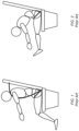
- FIGS. 1 and 2 illustrate examples of conventional seat belt assemblies for controlling forward movements in a vehicle such as an aircraft.
- FIG. 1 illustrates a conventional three-point assembly including a lap belt and a shoulder belt.
- FIG. 2 illustrates a conventional lap belt.
- the shoulder belt shown in FIG. 1 restrains the upper torso whereas the lap belt shown in FIG. 2 does not.
- the passenger movement shown in FIG. 2 is greater than the passenger movement shown in FIG. 1 , which may be referred to as a free-flail condition in which the body folds over about the waist.
- a passenger seated in a front row, or in a seat without a reachable forward structure for limiting forward movement may undergo free-flail during a sudden deceleration such as a crash.
- a passenger seat assembly including a seat including a seat back having a top, a bottom, lateral sides, a front, and a back.
- the assembly further includes a retractor positioned proximate the bottom of the seat back, a first slip ring affixed to the seat back proximate the top of the seat back, the first slip ring forming a first pivot, a second slip ring affixed to the seat back between the retractor and the first slip ring, the second ring forming a second pivot, and a webbing having a first end wound on the retractor, a second end positioned outside of the retractor, and the webbing threaded through each of the second slip ring and the first slip ring.
- the webbing In use, when a pulling force on the webbing is less than a predetermined threshold force value, the webbing is guided by the first pivot formed by the first slip ring. In use, when a pulling force on the webbing exceeds the predetermined threshold force value, the webbing is guided by the second pivot formed by the second slip ring.
- the first slip ring in use when the pulling force on the webbing exceeds the predetermined threshold force value, is configured to detach from the seat back.
- the first slip ring in use when the pulling force on the webbing exceeds the predetermined threshold force value, is configured to plastically deform to release the webbing.
- the retractor includes a rotating shaft, a lock configured to lock the rotating shaft against rotation, at least one sensor operative to output a signal when a sensed parameter exceeds a predetermined threshold value, and an activation device operative to activate the lock, the activation device communicatively coupled to the at least one sensor and operably coupled to the lock, and wherein upon receiving a signal output by the at least one sensor, the activation device is configured to activate the activation device thereby activating the lock.
- the sensed parameter includes at least one of rotational speed of the rotating shaft, pay out speed of the webbing, rotational acceleration of the rotating shaft, a number of rotations of the rotating shaft, loading on the webbing, loading on attachment structure of the retractor, and accelerations on the seat.
- the lock is a reel lock configured to lock the rotating shaft against rotation
- the at least one sensor is operative to output the signal when the sensed parameter of the rotating shaft exceeds the predetermined threshold value
- the activation device is configured to activate the reel lock
- the present disclosure provides a passenger seat assembly including a seat including a seat back having a top, a bottom, lateral sides, a front, and a back.
- the assembly further includes a retractor positioned proximate the bottom of the seat back, a slip ring affixed to the seat back proximate the top of the seat back, the slip ring forming a first pivot, a first webbing having a first end wound on the retractor, a second end positioned outside of the retractor, and the first webbing threaded through the slip ring, and a second webbing having a first end affixed proximate a bottom of the seat back and a second end affixed to the slip ring.
- a primary restraint formed by the first webbing is guided by the first pivot.
- an auxiliary restraint formed by the second webbing and a portion of the first webbing is guided by a second pivot associated with the second webbing.
- the first webbing includes a first portion, a second portion, and a coupler configured to releasably couple the first portion to the second portion, the first portion extends from the retractor to the coupler, the second portion extends from the coupler to the second end of the first webbing, and the coupler is positioned between the retractor and the slip ring.
- the coupler is configured to engage the slip ring and decouple the first portion of the first webbing from the second portion of the first webbing.
- the coupler in use when the pulling force exceeds the predetermined threshold force value, is configured to cause the slip ring to detach from the seat back.
- the coupler in use when the pulling force exceeds the predetermined threshold force value, is configured to cause the slip ring to undergo plastic deformation thereby releasing the first webbing.
- the slip ring is positioned proximate the top of the seat back, the second webbing is not attached to the first webbing, and the second pivot is positioned lower on the seat back as compared to the first pivot.
- the coupler is dimensioned larger than a guide opening formed through the slip ring such that the coupler is incapable of being pulled through the guide opening.
- the coupler when the predetermined threshold force value is exceeded, the coupler is configured to lockingly engage the slip ring.
- the present disclosure provides passenger seat assemblies including restraints configured to control forward movement during a sudden deceleration event such as a crash.
- Applications for the passenger seat assemblies described herein include, but are not limited to, aircraft and particularly front row passenger seats, exit row passenger seats, and other passenger seats without any forward structure reachable to limit forward movement.
- Benefits of the embodiments described herein include, but are not limited to, reducing spinal loads on the passenger, preserving the structural integrity of the passenger seat, and a reduction in the required structural reinforcement of the seat associated with the passenger restraints.
- FIG. 3 shows a passenger seat assembly 100 according to a first embodiment of the present disclosure.
- the assembly 100 includes a passenger seat 102 including a seat back 104.
- the passenger seat 102 may further include a seat bottom 106 and a frame or seat base 108 supporting each of the seat back 104 and the seat bottom 106 in a mounted condition to the aircraft deck.
- the seat back 104 may be fixed in an upright sitting position.
- the seat back 104 may be adjustable between an upright sitting position and a reclined sitting position.
- the seat back 104 may be coupled to the seat bottom 106.
- the seat back 104 may have any shape, however, generally includes a top, a bottom, opposing lateral sides, a front, and a back.
- the assembly further includes a first slip ring 110 affixed to the seat back 104 proximate the top of the seat back, and a second slip ring 112 affixed to the seat back 104 spaced apart from the first slip ring 110 in a direction of the bottom of the seat back 104.
- the second slip ring 112 is positioned lower on the seat back 104 as compared to the first slip ring 110, and in some instances about mid-span between the top and bottom or nearer to the bottom than to the top of the seat back.
- the first slip ring 110 also referred to herein as the "upper" slip ring, may be positioned closer to one lateral side as compared to the other such that the webbing may be pulled diagonally across the chest of the wearer.
- the second slip ring also referred to herein as the "lower" slip ring, may be positioned closer to one lateral side, along one lateral side, positioned proximate the back of the seat back under the dress cover, positioned internal to the seat back 104, or elsewhere.
- the first slip ring 110 is positioned outside of the seat back 104 and the second slip ring 112 is positioned inside the seat back, thus the second slip ring 112 may be concealed from view during normal use of the seat.
- the first slip ring 110 forms a first pivot, or "upper" pivot, about which the webbing changes direction as discussed further below.
- the first slip ring 110 is configured to detach, breakaway, or otherwise separate from the seat back 104, or alternatively undergo plastic deformation to release the captured webbing, thereby eliminating the first pivot and allowing the second slip ring 112 to form a new pivot, or "lower” pivot, about which the webbing also changes direction, but at a lower position along the height of the seat back 104 thereby reducing the bending moment on the constrained seat back.
- the second slip ring 112 does not function as a pivot, however, may cause a slight directional change in the webbing due to the webbing being threaded through the second
- a retractor 114 anchored proximate the bottom of the seat back 104 is configured to pay in and pay out the webbing.
- the retractor 114 may be affixed to the seat back, other seat structure, or to structure positioned alongside the seat.
- the webbing 116 includes a first end being wound on the retractor 114, and a second end positioned outside of the retractor 114. The second end, for example, may terminate in a buckle or connection to another webbing such as a lap belt.
- the webbing 116 is threaded through each of the first slip ring 110 and the second slip ring 112.
- the retractor 114 may be implemented as a reel including a rotating shaft 118 about which the webbing 116 is wound, and a reel lock 120 configured to lock the rotating shaft against rotation upon the occurrence of a sudden deceleration.
- the reel lock 120 in one embodiment may include a pawl configured to engage a toothed gear affixed to the shaft.
- the reel lock 120 may act directly on the webbing 116 to prevent further unwinding or pay out from the reel.
- the retractor 114 may be communicatively coupled to at least one sensor 122 operative to output a signal when a sensed parameter of the rotating shaft 118 exceeds a predetermined magnitude threshold.
- the sensed parameter may include at least one of rotational speed of the rotating shaft, rotational acceleration of the rotating shaft, and number of rotations of the rotating shaft, associated with an unwinding direction of the seat belt.
- the at least sensor 122 may be an acceleration sensor associated with the seat or other structure.
- An activation device 124 may be provided operative to activate the reel lock 120 to lock the rotating shaft 118 against rotation to prevent further unwinding or pay out of the webbing 116.
- the activation device 124 may or may not include a time delay device 126 electrically coupled to the at least one sensor 124 and in some embodiments an element of the activation device 124, is operative to, upon receiving the signal output by the at least one sensor 122, activate the activation device 124 upon completion of a time delay after receiving the signal output by the at least one sensor 122.
- the at least one sensor 122 is configured to detect changes in velocity of structures to which the sensors are connected or coupled, such as the components of at least one of the retractor 114, the webbing 116, the seat 102, or other structures in an aircraft passenger cabin or other structures of the aircraft overall such as fuselage and frame elements.
- the at least one sensor 122 may be configured to detect movements corresponding to high G-force events and may include any combination of multi-axis accelerometers, gyroscopes, and magnetometers, among others.
- accelerometers may be configured to measure an amount of acceleration in a particular direction
- gyroscopes may be configured to measure changes in orientation or relative velocity
- magnetometers measure changes in magnetic fields that can be used to determine absolute orientation of the elements to which the magnetometers are connected. Because accelerometers, gyroscopes, and magnetometers may be used to measure different features of inertial movement, the sensor outputs may be combined into or may otherwise contribute to connectivity.
- the at least one sensor 122 may be a ball and spring type acceleration switch that is generally maintained in a non-conducting condition in which a spring biases a ball from a conducting position.
- Such switches achieve electrically conducting conditions when actuated by acceleration greater than a predetermined magnitude threshold and return to non-conducting condition when the acceleration reduces below the threshold.
- the magnitude threshold of each such sensor can be predetermined, for example, by the spring constant of the spring and by the geometry of the device. In such a device, the ball, serving as an inertial mass, moves against the force of the spring to a conducting position to provide connectivity by either direct conduction through the ball or by otherwise engaging or actuating a switch with the ball during an inertial event.
- the magnitude threshold can be predetermined by selection of the acceleration sensors used or by adjustment of an acceleration sensors.
- the passenger seat assembly 100 is shown during normal use of the seat wherein the retractor 114 operates to pay in and out the webbing 116 and the first slip ring 110 guides the webbing 116 therethrough and causes the directional change of the webbing 116 about the upper pivot 128 formed by the first slip ring 110.
- FIG. 4 shows the passenger seat assembly 100 during a sudden deceleration, for instance an emergency situation, wherein the retractor 114 may be placed in a locked condition, the first slip ring 110 has detached from the seat back 104 or otherwise released the webbing, and the second slip ring 112, which remains affixed to the seat back 104, now guides the webbing 116 therethrough and causes the directional change of the webbing 116 about the lower pivot 130.
- the lower slip ring 112 guides the webbing 116 about the second pivot 130 at a lower area of the seat back 104 as compared to the upper pivot.
- the actual position of the lower slip ring 112 may depend on the seat design, for instance the position of structural elements configured to anchor the second slip ring 112 thereto to transfer loads to the seat.
- the second slip ring 112 serves as the new pivot when the first slip ring 110 separates from the seat back or plastically deforms thereby releasing the webbing 116.
- the pulling force on the webbing 116 sufficient to cause the first slip ring 110 to separate or release referred to herein as the predetermined threshold force value, may be for example about 250 lbs.
- seat belt assemblies are typically configured to survive abuse loads up to about 200 lbs. As such, the predetermined threshold load value may vary but is greater than the maximum abuse load value required of the assembly. Comparing FIGS. 2 and 4 shows how the assembly 100 functions to prevent free-flail thereby mitigating spinal tension. Comparing FIGS. 3 and 4 shows the movement of the upper torso.
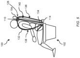
- FIG. 5 shows a passenger seat assembly 100 according to a further embodiment of the present disclosure.
- the assembly 100 also includes a passenger seat 102 including a seat back 104.
- the seat back 104 may be fixed in an upright sitting position.
- the seat back 104 may be adjustable between an upright sitting position and a reclined sitting position.
- the seat back 104 may be coupled to the seat bottom 106.
- the seat back 104 may have any shape, however, generally also includes a top, a bottom, opposing lateral sides, a front, and a back.
- the assembly 100 also includes an upper slip ring 110 affixed to the seat back 104 proximate the top of the seat back, which may be positioned closer to one lateral side of the seat back 102 as compared to the other such that the webbing may be pulled diagonally across the chest.
- the slip ring 110 forms a first or upper pivot 128 about which the webbing changes direction and the webbing travels through the slip ring 110 unimpeded.
- the slip ring 110 is also configured to detach, breakaway, or otherwise separate from the seat back 104 thereby eliminating the first pivot and allowing the webbing to pivot about a new, second or lower pivot about which the webbing changes direction, but at a lower position along the height of the seat back 104 thereby reducing the bending moment on the constrained seat back.
- high G-force events e.g. 16G or greater
- the webbing includes a first webbing 132, also referred to herein as the "primary" webbing, having a first end wound on the retractor 114, a second end positioned outside of the retractor 114, and the first webbing threaded through the slip ring 110.
- the webbing further includes a second, separate webbing 134, also referred to herein as the "secondary" webbing, having a first end anchored proximate a bottom of the seat back 104, and a second end affixed to the slip ring 110. In this configuration, the second webbing 134 does not interact with the retractor 114.
- the slip ring 110 is configured to detach from the seat back 104 thereby forming a new or second pivot associated with the second webbing 134.
- the first webbing 132 includes separate first and second portions 136, 138 releasably attached via a coupler 140. As shown, the first portion 136 extends from the retractor 114, such as the retractor described above, to the coupler 140, and the second portion extends from the coupler 140 to the second end of the first webbing 132.
- the coupler 140 when the pulling force on the first webbing 132 exceeds the predetermined threshold value, the coupler 140 is configured to engage the slip ring 110 (see FIG. 6 ) to thereby cause the slip ring 110 to separate or otherwise detach from the seat back 104, and also the first portion 136 of the first webbing 132 to detach from the coupler 140 as the pulling force on the first webbing 132 continues (see FIG. 7 ).
- FIG. 6 shows the passenger seat assembly 100 during a first stage of the emergency use condition wherein the coupler 140 travels to engage the slip ring 110, for instance locking engagement.
- the coupler 140 is dimensioned larger than the guide opening through the slip ring 110 such that the coupler 140 is incapable of being pulled through the guide opening. As the pulling force continues, the force of the coupler 140 against the slip ring 110 causes the slip ring 110 to detach, break, or otherwise separate from the seat back 104.
- FIG. 7 shows the passenger seat assembly 100 as the forward travel of the passenger and pulling force on the first webbing 132 continues.
- the continued pulling force causes the coupler 140 to detach from or otherwise release the first portion 136 of the first webbing 132.
- the attachment of the slip ring 110 to the second webbing 134 causes the second webbing 134 to join the movement of the second portion 138 of the first webbing 132.
- the second webbing 134 forms a new pivot, and in some embodiments the new pivot may be formed via a second slip ring, to allow the directional change of the second webbing 134 about the lower pivot, such as the pivot 130 shown in FIG. 7 .
- the position of the new pivot may depend on the seat design, attachment of the second webbing 134, etc.
- the force required to decouple the first portion 136 of the first webbing 132 from the coupler 140 is equal or greater than the force required to detach the slip ring 110 from the seat back 104. This ensures that the forward travel of the passenger is controlled to the point at which the coupler 140 is able to interact with the slip ring 110 to cause the detachment.
Landscapes
- Engineering & Computer Science (AREA)
- Mechanical Engineering (AREA)
- Automotive Seat Belt Assembly (AREA)
Abstract
Description
- The present disclosure relates generally to seat belt assemblies for vehicles such as aircraft, and more particularly, to shoulder belt assemblies configured to mitigate seat damage and spinal tension from free-flail movements that can occur during a sudden deceleration of a vehicle.
- Passenger restraints such as seat belts are designed to prevent serious injury during a sudden deceleration of a vehicle. Typical seat belts may be configured as lap belts, shoulder belts, and combinations thereof forming multi-point harnesses. Sophisticated seat belts may include pretensioners and load limiters. In use, pretensioners are configured to retract a seat belt to increase tension when a vehicle decelerates rapidly, while load limiters are configured to pay out a seat belt slightly when the tension exceeds a predetermined threshold. In some instances, the two work together to maintain the passenger generally against the seat while ensuring that the restraining forces acting on the passenger due not rise to a level that would cause injury.
-
FIGS. 1 and 2 illustrate examples of conventional seat belt assemblies for controlling forward movements in a vehicle such as an aircraft.FIG. 1 illustrates a conventional three-point assembly including a lap belt and a shoulder belt.FIG. 2 illustrates a conventional lap belt. During a sudden deceleration, the shoulder belt shown inFIG. 1 restrains the upper torso whereas the lap belt shown inFIG. 2 does not. As such, the passenger movement shown inFIG. 2 is greater than the passenger movement shown inFIG. 1 , which may be referred to as a free-flail condition in which the body folds over about the waist. In aircraft, a passenger seated in a front row, or in a seat without a reachable forward structure for limiting forward movement, may undergo free-flail during a sudden deceleration such as a crash. - It has been determined that free-flail movement subjects the passenger to spinal tension loads that may exceed a dangerous threshold. While shoulder belts may be effective at reducing spinal loading, conventional shoulder belt assemblies and attachments transfer significant loads through the seat structure. In the case of aircraft, an extreme deceleration and conventional shoulder belt attachment may cause significant seat deformation, particularly to the seat back. While increased loads may be mitigated by structurally reinforcing the seat, reinforcement adds weight, complexity, and cost to the seat, which is undesirable in aircraft applications.
- Therefore, what is needed is a solution for mitigating spinal tension while simultaneously preserving the structural integrity of the seat, without the disadvantages and limitations associated with conventional, sophisticated shoulder belt assemblies.
- To achieve the foregoing and other advantages, in a first aspect the present disclosure provides a passenger seat assembly including a seat including a seat back having a top, a bottom, lateral sides, a front, and a back. The assembly further includes a retractor positioned proximate the bottom of the seat back, a first slip ring affixed to the seat back proximate the top of the seat back, the first slip ring forming a first pivot, a second slip ring affixed to the seat back between the retractor and the first slip ring, the second ring forming a second pivot, and a webbing having a first end wound on the retractor, a second end positioned outside of the retractor, and the webbing threaded through each of the second slip ring and the first slip ring. In use, when a pulling force on the webbing is less than a predetermined threshold force value, the webbing is guided by the first pivot formed by the first slip ring. In use, when a pulling force on the webbing exceeds the predetermined threshold force value, the webbing is guided by the second pivot formed by the second slip ring.
- In some embodiments, in use when the pulling force on the webbing exceeds the predetermined threshold force value, the first slip ring is configured to detach from the seat back.
- In some embodiments, in use when the pulling force on the webbing exceeds the predetermined threshold force value, the first slip ring is configured to plastically deform to release the webbing.
- In some embodiments, the retractor includes a rotating shaft, a lock configured to lock the rotating shaft against rotation, at least one sensor operative to output a signal when a sensed parameter exceeds a predetermined threshold value, and an activation device operative to activate the lock, the activation device communicatively coupled to the at least one sensor and operably coupled to the lock, and wherein upon receiving a signal output by the at least one sensor, the activation device is configured to activate the activation device thereby activating the lock.
- In some embodiments, the sensed parameter includes at least one of rotational speed of the rotating shaft, pay out speed of the webbing, rotational acceleration of the rotating shaft, a number of rotations of the rotating shaft, loading on the webbing, loading on attachment structure of the retractor, and accelerations on the seat.
- In some embodiments, the lock is a reel lock configured to lock the rotating shaft against rotation, the at least one sensor is operative to output the signal when the sensed parameter of the rotating shaft exceeds the predetermined threshold value, and the activation device is configured to activate the reel lock.
- According to another aspect, the present disclosure provides a passenger seat assembly including a seat including a seat back having a top, a bottom, lateral sides, a front, and a back. The assembly further includes a retractor positioned proximate the bottom of the seat back, a slip ring affixed to the seat back proximate the top of the seat back, the slip ring forming a first pivot, a first webbing having a first end wound on the retractor, a second end positioned outside of the retractor, and the first webbing threaded through the slip ring, and a second webbing having a first end affixed proximate a bottom of the seat back and a second end affixed to the slip ring. In use, when a pulling force on the first webbing is less than a predetermined threshold force value, a primary restraint formed by the first webbing is guided by the first pivot. In use, when a pulling force on the first webbing exceeds the predetermined threshold force value, an auxiliary restraint formed by the second webbing and a portion of the first webbing is guided by a second pivot associated with the second webbing.
- In some embodiments, the first webbing includes a first portion, a second portion, and a coupler configured to releasably couple the first portion to the second portion, the first portion extends from the retractor to the coupler, the second portion extends from the coupler to the second end of the first webbing, and the coupler is positioned between the retractor and the slip ring. In use, when the pulling force on the first webbing exceeds the predetermined threshold force value, the coupler is configured to engage the slip ring and decouple the first portion of the first webbing from the second portion of the first webbing.
- In some embodiments, in use when the pulling force exceeds the predetermined threshold force value, the coupler is configured to cause the slip ring to detach from the seat back.
- In some embodiments, in use when the pulling force exceeds the predetermined threshold force value, the coupler is configured to cause the slip ring to undergo plastic deformation thereby releasing the first webbing.
- In some embodiments, the slip ring is positioned proximate the top of the seat back, the second webbing is not attached to the first webbing, and the second pivot is positioned lower on the seat back as compared to the first pivot.
- In some embodiments, the coupler is dimensioned larger than a guide opening formed through the slip ring such that the coupler is incapable of being pulled through the guide opening.
- In some embodiments, when the predetermined threshold force value is exceeded, the coupler is configured to lockingly engage the slip ring.
- Implementations of the inventive concepts disclosed herein may be better understood when consideration is given to the following detailed description thereof. Such description makes reference to the included drawings, which are not necessarily to scale, and in which some features may be exaggerated, and some features may be omitted or may be represented schematically in the interest of clarity. Like reference numbers in the drawings may represent and refer to the same or similar element, feature, or function. In the drawings:
-
FIG. 1 is a schematic diagram showing use of a conventional shoulder belt for restraining passenger motion during a sudden deceleration; -
FIG. 2 is a schematic diagram showing use of a conventional lap belt for restraining passenger motion during a sudden deceleration and the resulting free-flail body movement; -
FIG. 3 is a schematic diagram showing a passenger seat assembly according to the present disclosure, during normal use prior to any sudden deceleration; -
FIG. 4 is a schematic diagram showing the passenger seat assembly ofFIG. 3 in use during a sudden deceleration; -
FIG. 5 is a schematic diagram showing a passenger seat assembly according to a further embodiment of the present disclosure, during normal use prior to any sudden deceleration; -
FIG. 6 is a schematic diagram showing the passenger seat assembly ofFIG. 5 at the moment of first occurrence of a sudden deceleration; and -
FIG. 7 is a schematic diagram showing the passenger seat assembly ofFIGS. 5 and6 as the sudden deceleration continues. - The description set forth below in connection with the appended drawings is intended to be a description of various, illustrative embodiments of the disclosed subject matter. Specific features and functionalities are described in connection with each illustrative embodiment; however, it will be apparent to those skilled in the art that the disclosed embodiments may be practiced without each of those specific features and functionalities. The aspects, features and functions described below in connection with one embodiment are intended to be applicable to the other embodiments described below except where expressly stated or where an aspect, feature or function is incompatible with an embodiment.
- Broadly, the present disclosure provides passenger seat assemblies including restraints configured to control forward movement during a sudden deceleration event such as a crash. Applications for the passenger seat assemblies described herein include, but are not limited to, aircraft and particularly front row passenger seats, exit row passenger seats, and other passenger seats without any forward structure reachable to limit forward movement. Benefits of the embodiments described herein include, but are not limited to, reducing spinal loads on the passenger, preserving the structural integrity of the passenger seat, and a reduction in the required structural reinforcement of the seat associated with the passenger restraints.
-
FIG. 3 shows apassenger seat assembly 100 according to a first embodiment of the present disclosure. Theassembly 100 includes apassenger seat 102 including aseat back 104. Thepassenger seat 102 may further include aseat bottom 106 and a frame orseat base 108 supporting each of the seat back 104 and theseat bottom 106 in a mounted condition to the aircraft deck. In some embodiments, theseat back 104 may be fixed in an upright sitting position. In other embodiments, theseat back 104 may be adjustable between an upright sitting position and a reclined sitting position. In some embodiments, theseat back 104 may be coupled to theseat bottom 106. Theseat back 104 may have any shape, however, generally includes a top, a bottom, opposing lateral sides, a front, and a back. - The assembly further includes a
first slip ring 110 affixed to the seat back 104 proximate the top of the seat back, and asecond slip ring 112 affixed to the seat back 104 spaced apart from thefirst slip ring 110 in a direction of the bottom of the seat back 104. As shown, thesecond slip ring 112 is positioned lower on the seat back 104 as compared to thefirst slip ring 110, and in some instances about mid-span between the top and bottom or nearer to the bottom than to the top of the seat back. Thefirst slip ring 110, also referred to herein as the "upper" slip ring, may be positioned closer to one lateral side as compared to the other such that the webbing may be pulled diagonally across the chest of the wearer. The second slip ring, also referred to herein as the "lower" slip ring, may be positioned closer to one lateral side, along one lateral side, positioned proximate the back of the seat back under the dress cover, positioned internal to the seat back 104, or elsewhere. In some embodiments, thefirst slip ring 110 is positioned outside of the seat back 104 and thesecond slip ring 112 is positioned inside the seat back, thus thesecond slip ring 112 may be concealed from view during normal use of the seat. - During normal use of the seat corresponding to low G-force events and loading less than a predetermined threshold force value as described herein, the
first slip ring 110 forms a first pivot, or "upper" pivot, about which the webbing changes direction as discussed further below. During emergency use of the seat corresponding to high G-force events (e.g., 16G or greater) and loading exceeding the predetermined threshold force value, thefirst slip ring 110 is configured to detach, breakaway, or otherwise separate from the seat back 104, or alternatively undergo plastic deformation to release the captured webbing, thereby eliminating the first pivot and allowing thesecond slip ring 112 to form a new pivot, or "lower" pivot, about which the webbing also changes direction, but at a lower position along the height of the seat back 104 thereby reducing the bending moment on the constrained seat back. During normal use of the seat, thesecond slip ring 112 does not function as a pivot, however, may cause a slight directional change in the webbing due to the webbing being threaded through thesecond slip ring 112. - A
retractor 114 anchored proximate the bottom of the seat back 104 is configured to pay in and pay out the webbing. Theretractor 114 may be affixed to the seat back, other seat structure, or to structure positioned alongside the seat. Thewebbing 116 includes a first end being wound on theretractor 114, and a second end positioned outside of theretractor 114. The second end, for example, may terminate in a buckle or connection to another webbing such as a lap belt. Thewebbing 116 is threaded through each of thefirst slip ring 110 and thesecond slip ring 112. - In some embodiments, the
retractor 114 may be implemented as a reel including arotating shaft 118 about which thewebbing 116 is wound, and areel lock 120 configured to lock the rotating shaft against rotation upon the occurrence of a sudden deceleration. For example, thereel lock 120 in one embodiment may include a pawl configured to engage a toothed gear affixed to the shaft. In some embodiments, thereel lock 120 may act directly on thewebbing 116 to prevent further unwinding or pay out from the reel. - In some embodiments, the
retractor 114 may be communicatively coupled to at least onesensor 122 operative to output a signal when a sensed parameter of therotating shaft 118 exceeds a predetermined magnitude threshold. For example, the sensed parameter may include at least one of rotational speed of the rotating shaft, rotational acceleration of the rotating shaft, and number of rotations of the rotating shaft, associated with an unwinding direction of the seat belt. In some embodiments, the at leastsensor 122 may be an acceleration sensor associated with the seat or other structure. Anactivation device 124 may be provided operative to activate thereel lock 120 to lock therotating shaft 118 against rotation to prevent further unwinding or pay out of thewebbing 116. Theactivation device 124 may or may not include atime delay device 126 electrically coupled to the at least onesensor 124 and in some embodiments an element of theactivation device 124, is operative to, upon receiving the signal output by the at least onesensor 122, activate theactivation device 124 upon completion of a time delay after receiving the signal output by the at least onesensor 122. - In some embodiments, the at least one
sensor 122 is configured to detect changes in velocity of structures to which the sensors are connected or coupled, such as the components of at least one of theretractor 114, thewebbing 116, theseat 102, or other structures in an aircraft passenger cabin or other structures of the aircraft overall such as fuselage and frame elements. The at least onesensor 122 may be configured to detect movements corresponding to high G-force events and may include any combination of multi-axis accelerometers, gyroscopes, and magnetometers, among others. In some implementations, accelerometers may be configured to measure an amount of acceleration in a particular direction, gyroscopes may be configured to measure changes in orientation or relative velocity, and magnetometers measure changes in magnetic fields that can be used to determine absolute orientation of the elements to which the magnetometers are connected. Because accelerometers, gyroscopes, and magnetometers may be used to measure different features of inertial movement, the sensor outputs may be combined into or may otherwise contribute to connectivity. - In some embodiments, the at least one
sensor 122 may be a ball and spring type acceleration switch that is generally maintained in a non-conducting condition in which a spring biases a ball from a conducting position. Such switches achieve electrically conducting conditions when actuated by acceleration greater than a predetermined magnitude threshold and return to non-conducting condition when the acceleration reduces below the threshold. The magnitude threshold of each such sensor can be predetermined, for example, by the spring constant of the spring and by the geometry of the device. In such a device, the ball, serving as an inertial mass, moves against the force of the spring to a conducting position to provide connectivity by either direct conduction through the ball or by otherwise engaging or actuating a switch with the ball during an inertial event. Thus, the magnitude threshold can be predetermined by selection of the acceleration sensors used or by adjustment of an acceleration sensors. - With continued reference to
FIG. 3 , thepassenger seat assembly 100 is shown during normal use of the seat wherein theretractor 114 operates to pay in and out thewebbing 116 and thefirst slip ring 110 guides thewebbing 116 therethrough and causes the directional change of thewebbing 116 about theupper pivot 128 formed by thefirst slip ring 110. -
FIG. 4 shows thepassenger seat assembly 100 during a sudden deceleration, for instance an emergency situation, wherein theretractor 114 may be placed in a locked condition, thefirst slip ring 110 has detached from the seat back 104 or otherwise released the webbing, and thesecond slip ring 112, which remains affixed to the seat back 104, now guides thewebbing 116 therethrough and causes the directional change of thewebbing 116 about thelower pivot 130. In use, during a sudden deceleration of sufficient magnitude, thelower slip ring 112 guides thewebbing 116 about thesecond pivot 130 at a lower area of the seat back 104 as compared to the upper pivot. The actual position of thelower slip ring 112 may depend on the seat design, for instance the position of structural elements configured to anchor thesecond slip ring 112 thereto to transfer loads to the seat. Thesecond slip ring 112 serves as the new pivot when thefirst slip ring 110 separates from the seat back or plastically deforms thereby releasing thewebbing 116. The pulling force on thewebbing 116 sufficient to cause thefirst slip ring 110 to separate or release, referred to herein as the predetermined threshold force value, may be for example about 250 lbs. Known to those skilled in the art, seat belt assemblies are typically configured to survive abuse loads up to about 200 lbs. As such, the predetermined threshold load value may vary but is greater than the maximum abuse load value required of the assembly. ComparingFIGS. 2 and4 shows how theassembly 100 functions to prevent free-flail thereby mitigating spinal tension. ComparingFIGS. 3 and4 shows the movement of the upper torso. -
FIG. 5 shows apassenger seat assembly 100 according to a further embodiment of the present disclosure. Theassembly 100 also includes apassenger seat 102 including a seat back 104. In some embodiments, the seat back 104 may be fixed in an upright sitting position. In other embodiments, the seat back 104 may be adjustable between an upright sitting position and a reclined sitting position. In some embodiments, the seat back 104 may be coupled to theseat bottom 106. The seat back 104 may have any shape, however, generally also includes a top, a bottom, opposing lateral sides, a front, and a back. - The
assembly 100 also includes anupper slip ring 110 affixed to the seat back 104 proximate the top of the seat back, which may be positioned closer to one lateral side of the seat back 102 as compared to the other such that the webbing may be pulled diagonally across the chest. During normal use of the seat corresponding to low G-force events and loading less than a predetermined threshold force value, theslip ring 110 forms a first orupper pivot 128 about which the webbing changes direction and the webbing travels through theslip ring 110 unimpeded. During a sudden deceleration, such as an emergency situation of the seat corresponding to high G-force events (e.g., 16G or greater) and loading exceeding the predetermined threshold value, theslip ring 110 is also configured to detach, breakaway, or otherwise separate from the seat back 104 thereby eliminating the first pivot and allowing the webbing to pivot about a new, second or lower pivot about which the webbing changes direction, but at a lower position along the height of the seat back 104 thereby reducing the bending moment on the constrained seat back. - The second embodiment differs from the first embodiment described above in terms of the webbing configuration. In the second or further embodiment, the webbing includes a
first webbing 132, also referred to herein as the "primary" webbing, having a first end wound on theretractor 114, a second end positioned outside of theretractor 114, and the first webbing threaded through theslip ring 110. The webbing further includes a second,separate webbing 134, also referred to herein as the "secondary" webbing, having a first end anchored proximate a bottom of the seat back 104, and a second end affixed to theslip ring 110. In this configuration, thesecond webbing 134 does not interact with theretractor 114. - In use, when the pulling force on the first webbing exceeds the predetermined threshold force value (e.g., about 250 lbs.), the
slip ring 110 is configured to detach from the seat back 104 thereby forming a new or second pivot associated with thesecond webbing 134. Thefirst webbing 132 includes separate first andsecond portions coupler 140. As shown, thefirst portion 136 extends from theretractor 114, such as the retractor described above, to thecoupler 140, and the second portion extends from thecoupler 140 to the second end of thefirst webbing 132. - Referring to
FIGS. 6 and7 , when the pulling force on thefirst webbing 132 exceeds the predetermined threshold value, thecoupler 140 is configured to engage the slip ring 110 (seeFIG. 6 ) to thereby cause theslip ring 110 to separate or otherwise detach from the seat back 104, and also thefirst portion 136 of thefirst webbing 132 to detach from thecoupler 140 as the pulling force on thefirst webbing 132 continues (seeFIG. 7 ). -
FIG. 6 shows thepassenger seat assembly 100 during a first stage of the emergency use condition wherein thecoupler 140 travels to engage theslip ring 110, for instance locking engagement. Thecoupler 140 is dimensioned larger than the guide opening through theslip ring 110 such that thecoupler 140 is incapable of being pulled through the guide opening. As the pulling force continues, the force of thecoupler 140 against theslip ring 110 causes theslip ring 110 to detach, break, or otherwise separate from the seat back 104. -
FIG. 7 shows thepassenger seat assembly 100 as the forward travel of the passenger and pulling force on thefirst webbing 132 continues. As thecoupler 140 interacts with theslip ring 110 to cause the detachment, the continued pulling force causes thecoupler 140 to detach from or otherwise release thefirst portion 136 of thefirst webbing 132. The attachment of theslip ring 110 to thesecond webbing 134 causes thesecond webbing 134 to join the movement of thesecond portion 138 of thefirst webbing 132. Thesecond webbing 134 forms a new pivot, and in some embodiments the new pivot may be formed via a second slip ring, to allow the directional change of thesecond webbing 134 about the lower pivot, such as thepivot 130 shown inFIG. 7 . The position of the new pivot may depend on the seat design, attachment of thesecond webbing 134, etc. - The force required to decouple the
first portion 136 of thefirst webbing 132 from thecoupler 140 is equal or greater than the force required to detach theslip ring 110 from the seat back 104. This ensures that the forward travel of the passenger is controlled to the point at which thecoupler 140 is able to interact with theslip ring 110 to cause the detachment. - While the foregoing description provides embodiments of the invention by way of example only, it is envisioned that other embodiments may perform similar functions and/or achieve similar results. Any and all such equivalent embodiments and examples are within the scope of the present invention and are intended to be covered by the appended claims.
Claims (15)
- A passenger seat assembly (100), comprising:a seat (102) including a seat back (104) having a top, a bottom, lateral sides, a front, and a back;a retractor (114) positioned proximate the bottom of the seat back;a first slip ring (110) affixed to the seat back proximate the top of the seat back, the first slip ring forming a first pivot;a second slip ring (112) affixed to the seat back between the retractor and the first slip ring, the second ring forming a second pivot; anda webbing (116) having a first end wound on the retractor, a second end positioned outside of the retractor, and the webbing threaded through each of the second slip ring (112) and the first slip ring (110);wherein:in use, when a pulling force on the webbing (116) is less than a predetermined threshold force value, the webbing is guided by the first pivot formed by the first slip ring (110); andin use, when a pulling force on the webbing (116) exceeds the predetermined threshold force value, the webbing is guided by the second pivot formed by the second slip ring (112).
- The passenger seat assembly (100) according to claim 1, wherein in use, when the pulling force on the webbing (116) exceeds the predetermined threshold force value, the first slip ring (110) is configured to detach from the seat back.
- The passenger seat assembly (100) according to claim 1, wherein in use, when the pulling force on the webbing (116) exceeds the predetermined threshold force value, the first slip ring (110) is configured to plastically deform to release the webbing.
- The passenger seat assembly (100) according to claim 1, wherein the retractor comprises:a rotating shaft (118);a lock configured to lock the rotating shaft against rotation;at least one sensor (122) operative to output a signal when a sensed parameter exceeds a predetermined threshold value; andan activation device operative to activate the lock, the activation device communicatively coupled to the at least one sensor and operably coupled to the lock, and wherein upon receiving a signal output by the at least one sensor, the activation device is configured to activate the activation device thereby activating the lock.
- The passenger seat assembly (100) according to claim 4, wherein the sensed parameter includes at least one of rotational speed of the rotating shaft, pay out speed of the webbing, rotational acceleration of the rotating shaft, a number of rotations of the rotating shaft, loading on the webbing, loading on attachment structure of the retractor, and accelerations on the seat.
- The passenger seat assembly (100) according to claim 5, wherein:the lock is a reel lock configured to lock the rotating shaft (118) against rotation;the at least one sensor (122) is operative to output the signal when the sensed parameter of the rotating shaft exceeds the predetermined threshold value; andthe activation device is configured to activate the reel lock.
- A passenger seat assembly (100), comprising:a seat (102) including a seat back (104) having a top, a bottom, lateral sides, a front, and a back;a retractor (114) positioned proximate the bottom of the seat back;a slip ring (110) affixed to the seat back proximate the top of the seat back, the slip ring forming a first pivot;a first webbing (132) having a first end wound on the retractor, a second end positioned outside of the retractor, and the first webbing threaded through the slip ring; anda second webbing (134) having a first end affixed proximate a bottom of the seat back and a second end affixed to the slip ring;wherein:in use, when a pulling force on the first webbing (132) is less than a predetermined threshold force value, a primary restraint formed by the first webbing is guided by the first pivot; andin use, when a pulling force on the first webbing (132) exceeds the predetermined threshold force value, an auxiliary restraint formed by the second webbing (134) and a portion of the first webbing is guided by a second pivot associated with the second webbing.
- The passenger seat assembly (100) according to claim 7, wherein:the first webbing (132) includes a first portion(136), a second portion (138), and a coupler (140) configured to releasably couple the first portion to the second portion;the first portion (136) extends from the retractor to the coupler;the second portion (138) extends from the coupler to the second end of the first webbing; andthe coupler (140) is positioned between the retractor and the slip ring;wherein, in use, when the pulling force on the first webbing (132) exceeds the predetermined threshold force value, the coupler (140) is configured to engage the slip ring (110) and decouple the first portion of the first webbing from the second portion of the first webbing.
- The passenger seat assembly (100) according to claim 8, wherein in use, when the pulling force exceeds the predetermined threshold force value, the coupler (140) is configured to cause the slip ring (110) to detach from the seat back (102).
- The passenger seat assembly (100) according to claim 8, wherein in use, when the pulling force exceeds the predetermined threshold force value, the coupler (140) is configured to cause the slip ring (110) to undergo plastic deformation thereby releasing the first webbing (132).
- The passenger seat assembly (100) according to claim 7, wherein:the slip ring (110) is positioned proximate the top of the seat back (102);the second webbing (134) is not attached to the first webbing (132); andthe second pivot is positioned lower on the seat back as compared to the first pivot.
- The passenger seat assembly (100) according to claim 8, wherein;the coupler (140) is larger than a guide opening formed through the slip ring (110) such that the coupler is incapable of being pulled through the guide opening; andwhen the predetermined threshold force value is exceeded, the coupler (140) is configured to lockingly engage the slip ring (110).
- The passenger seat assembly (100) according to claim 8, wherein the retractor (114) comprises:a rotating shaft (118);a lock configured to lock the rotating shaft against rotation;at least one sensor (122) operative to output a signal when a sensed parameter exceeds a predetermined threshold value; andan activation device operative to activate the lock, the activation device communicatively coupled to the at least one sensor and operably coupled to the lock, and wherein upon receiving a signal output by the at least one sensor, the activation device is configured to activate the activation device thereby activating the lock.
- The passenger seat assembly (100) according to claim 13, wherein the sensed parameter includes at least one of rotational speed of the rotating shaft, pay out speed of the webbing, rotational acceleration of the rotating shaft, a number of rotations of the rotating shaft, loading on the webbing, loading on attachment structure of the retractor, and accelerations on the seat.
- The passenger seat assembly (100) according to claim 13, wherein:the lock is a reel lock configured to lock the rotating shaft against rotation;the at least one sensor (122) is operative to output the signal when the sensed parameter of the rotating shaft exceeds the predetermined threshold value; andthe activation device is configured to activate the reel lock.
Applications Claiming Priority (1)
| Application Number | Priority Date | Filing Date | Title |
|---|---|---|---|
| US18/105,656 US12060034B1 (en) | 2023-02-03 | 2023-02-03 | Seat belt assemblies for mitigating spinal tension during free-flail |
Publications (2)
| Publication Number | Publication Date |
|---|---|
| EP4410608A1 true EP4410608A1 (en) | 2024-08-07 |
| EP4410608B1 EP4410608B1 (en) | 2026-02-25 |
Family
ID=89661557
Family Applications (1)
| Application Number | Title | Priority Date | Filing Date |
|---|---|---|---|
| EP24152596.3A Active EP4410608B1 (en) | 2023-02-03 | 2024-01-18 | Seat belt assemblies for mitigating spinal tension during free-flail |
Country Status (2)
| Country | Link |
|---|---|
| US (1) | US12060034B1 (en) |
| EP (1) | EP4410608B1 (en) |
Citations (5)
| Publication number | Priority date | Publication date | Assignee | Title |
|---|---|---|---|---|
| EP2045147A1 (en) * | 2007-10-03 | 2009-04-08 | Key Safety Systems, Inc. | Seat belt system for adults and children |
| US20120212029A1 (en) * | 2010-03-23 | 2012-08-23 | Komatsu Ltd. | Seat Belt and Construction Machine Equipped Therewith |
| AT13503U1 (en) * | 2013-01-02 | 2014-02-15 | Fasching Salzburg Gmbh | Height-adjustable holding device |
| EP2719576A1 (en) * | 2012-10-12 | 2014-04-16 | Tribus B.V. | Vehicle with an adjustable seat belt system and a seat belt system |
| EP4257437A1 (en) * | 2022-03-29 | 2023-10-11 | B/E Aerospace, Inc. | Passenger restraints for reducing spinal tension |
Family Cites Families (12)
| Publication number | Priority date | Publication date | Assignee | Title |
|---|---|---|---|---|
| US4256330A (en) | 1979-12-20 | 1981-03-17 | Ford Motor Company | Passive seat belt system |
| US5547143A (en) * | 1994-08-24 | 1996-08-20 | Alliedsignal Inc. | Seat belt retractor with integrated load limiter |
| US5823627A (en) * | 1997-04-11 | 1998-10-20 | General Motors Corporation | Vehicle seat with integral, load limiting belt system |
| DE10230483A1 (en) | 2002-07-06 | 2004-01-15 | Robert Bosch Gmbh | Procedure for controlling a two-stage belt tensioner |
| ATE388055T1 (en) | 2005-07-12 | 2008-03-15 | Key Safety Systems Inc | BELT TENSIONER |
| DE602006007157D1 (en) * | 2006-11-29 | 2009-07-16 | Key Safety Systems Inc | Safety restraint system for a child |
| FR2995849B1 (en) * | 2012-09-27 | 2015-06-26 | Peugeot Citroen Automobiles Sa | SECURITY BELT REEL SUPPORT WITH PROGRAMMED DEFORMATION. |
| US9561777B2 (en) * | 2012-11-28 | 2017-02-07 | Key Safety Systems, Inc. | Safe belt |
| US9821759B2 (en) * | 2015-03-05 | 2017-11-21 | Ford Global Technologies, Llc | Seat-belt mounting system |
| CN109249891B (en) * | 2017-07-12 | 2020-09-18 | 王亮雄 | buffer device |
| US10518740B2 (en) | 2018-02-27 | 2019-12-31 | Ford Global Technologies, Llc | Seatbelt assembly |
| WO2021221652A1 (en) * | 2020-04-30 | 2021-11-04 | Safran Seats Usa Llc | Passenger seat arrest mechanism |
-
2023
- 2023-02-03 US US18/105,656 patent/US12060034B1/en active Active
-
2024
- 2024-01-18 EP EP24152596.3A patent/EP4410608B1/en active Active
Patent Citations (5)
| Publication number | Priority date | Publication date | Assignee | Title |
|---|---|---|---|---|
| EP2045147A1 (en) * | 2007-10-03 | 2009-04-08 | Key Safety Systems, Inc. | Seat belt system for adults and children |
| US20120212029A1 (en) * | 2010-03-23 | 2012-08-23 | Komatsu Ltd. | Seat Belt and Construction Machine Equipped Therewith |
| EP2719576A1 (en) * | 2012-10-12 | 2014-04-16 | Tribus B.V. | Vehicle with an adjustable seat belt system and a seat belt system |
| AT13503U1 (en) * | 2013-01-02 | 2014-02-15 | Fasching Salzburg Gmbh | Height-adjustable holding device |
| EP4257437A1 (en) * | 2022-03-29 | 2023-10-11 | B/E Aerospace, Inc. | Passenger restraints for reducing spinal tension |
Also Published As
| Publication number | Publication date |
|---|---|
| EP4410608B1 (en) | 2026-02-25 |
| US20240262313A1 (en) | 2024-08-08 |
| US12060034B1 (en) | 2024-08-13 |
Similar Documents
| Publication | Publication Date | Title |
|---|---|---|
| EP0764097B1 (en) | Vehicle safety restraints | |
| US7988196B2 (en) | Lap loop three point seatbelt system | |
| US8302995B2 (en) | Method of controlling a four-point occupant restraint belt system | |
| EP2045147A1 (en) | Seat belt system for adults and children | |
| EP4257437B1 (en) | Passenger restraints for reducing spinal tension | |
| US20090309346A1 (en) | Intelligent Vehicle Safety Restraint System | |
| US7114590B2 (en) | Vehicle occupant protection system including a device for sensing tension in seat belt webbing | |
| EP2377417B1 (en) | Belt latch for a safety belt | |
| WO2004009411A1 (en) | Vehicle seat belt system | |
| US10752202B2 (en) | Three-point seat belt with additional safety features | |
| EP4410608B1 (en) | Seat belt assemblies for mitigating spinal tension during free-flail | |
| US20230036452A1 (en) | Dual three-point restraint system | |
| JP2001287622A (en) | Vehicle seat belt pretensioner operating method | |
| JP6284501B2 (en) | Seat belt device | |
| JP2001522332A (en) | Retractor | |
| US4289328A (en) | Seat belt system | |
| EP1942036B1 (en) | Length compensating seat belt restraint system | |
| EP2243670A1 (en) | Side Facing Restraint System | |
| EP2460697B1 (en) | Seat belt device | |
| US20120283916A1 (en) | Occupant restraint system | |
| EP3431349B1 (en) | Twin shoulder strap harness retractor assembly | |
| CN116691593A (en) | Load limiting seat belt retractor | |
| JP7739875B2 (en) | seat belt device | |
| US4286805A (en) | Seatbelt system | |
| JP2023077043A (en) | sheet |
Legal Events
| Date | Code | Title | Description |
|---|---|---|---|
| PUAI | Public reference made under article 153(3) epc to a published international application that has entered the european phase |
Free format text: ORIGINAL CODE: 0009012 |
|
| STAA | Information on the status of an ep patent application or granted ep patent |
Free format text: STATUS: THE APPLICATION HAS BEEN PUBLISHED |
|
| AK | Designated contracting states |
Kind code of ref document: A1 Designated state(s): AL AT BE BG CH CY CZ DE DK EE ES FI FR GB GR HR HU IE IS IT LI LT LU LV MC ME MK MT NL NO PL PT RO RS SE SI SK SM TR |
|
| STAA | Information on the status of an ep patent application or granted ep patent |
Free format text: STATUS: REQUEST FOR EXAMINATION WAS MADE |
|
| 17P | Request for examination filed |
Effective date: 20240904 |
|
| RBV | Designated contracting states (corrected) |
Designated state(s): AL AT BE BG CH CY CZ DE DK EE ES FI FR GB GR HR HU IE IS IT LI LT LU LV MC ME MK MT NL NO PL PT RO RS SE SI SK SM TR |
|
| GRAP | Despatch of communication of intention to grant a patent |
Free format text: ORIGINAL CODE: EPIDOSNIGR1 |
|
| STAA | Information on the status of an ep patent application or granted ep patent |
Free format text: STATUS: GRANT OF PATENT IS INTENDED |
|
| INTG | Intention to grant announced |
Effective date: 20250829 |
|
| GRAS | Grant fee paid |
Free format text: ORIGINAL CODE: EPIDOSNIGR3 |
|
| GRAA | (expected) grant |
Free format text: ORIGINAL CODE: 0009210 |
|
| STAA | Information on the status of an ep patent application or granted ep patent |
Free format text: STATUS: THE PATENT HAS BEEN GRANTED |
|
| AK | Designated contracting states |
Kind code of ref document: B1 Designated state(s): AL AT BE BG CH CY CZ DE DK EE ES FI FR GB GR HR HU IE IS IT LI LT LU LV MC ME MK MT NL NO PL PT RO RS SE SI SK SM TR |
|
| REG | Reference to a national code |
Ref country code: CH Ref legal event code: F10 Free format text: ST27 STATUS EVENT CODE: U-0-0-F10-F00 (AS PROVIDED BY THE NATIONAL OFFICE) Effective date: 20260225 Ref country code: GB Ref legal event code: FG4D |
|
| REG | Reference to a national code |
Ref country code: DE Ref legal event code: R096 Ref document number: 602024002702 Country of ref document: DE |
|
| REG | Reference to a national code |
Ref country code: IE Ref legal event code: FG4D |
|
| REG | Reference to a national code |
Ref country code: NL Ref legal event code: MP Effective date: 20260225 |
|
| PG25 | Lapsed in a contracting state [announced via postgrant information from national office to epo] |
Ref country code: RS Free format text: LAPSE BECAUSE OF FAILURE TO SUBMIT A TRANSLATION OF THE DESCRIPTION OR TO PAY THE FEE WITHIN THE PRESCRIBED TIME-LIMIT Effective date: 20260525 |
|
| PG25 | Lapsed in a contracting state [announced via postgrant information from national office to epo] |
Ref country code: ES Free format text: LAPSE BECAUSE OF FAILURE TO SUBMIT A TRANSLATION OF THE DESCRIPTION OR TO PAY THE FEE WITHIN THE PRESCRIBED TIME-LIMIT Effective date: 20260225 |
|
| PG25 | Lapsed in a contracting state [announced via postgrant information from national office to epo] |
Ref country code: PL Free format text: LAPSE BECAUSE OF FAILURE TO SUBMIT A TRANSLATION OF THE DESCRIPTION OR TO PAY THE FEE WITHIN THE PRESCRIBED TIME-LIMIT Effective date: 20260225 |
|
| PG25 | Lapsed in a contracting state [announced via postgrant information from national office to epo] |
Ref country code: GR Free format text: LAPSE BECAUSE OF FAILURE TO SUBMIT A TRANSLATION OF THE DESCRIPTION OR TO PAY THE FEE WITHIN THE PRESCRIBED TIME-LIMIT Effective date: 20260526 |
|
| REG | Reference to a national code |
Ref country code: LT Ref legal event code: MG9D |
|
| PG25 | Lapsed in a contracting state [announced via postgrant information from national office to epo] |
Ref country code: LT Free format text: LAPSE BECAUSE OF FAILURE TO SUBMIT A TRANSLATION OF THE DESCRIPTION OR TO PAY THE FEE WITHIN THE PRESCRIBED TIME-LIMIT Effective date: 20260225 |
|
| PG25 | Lapsed in a contracting state [announced via postgrant information from national office to epo] |
Ref country code: NO Free format text: LAPSE BECAUSE OF FAILURE TO SUBMIT A TRANSLATION OF THE DESCRIPTION OR TO PAY THE FEE WITHIN THE PRESCRIBED TIME-LIMIT Effective date: 20260525 |
|
| PG25 | Lapsed in a contracting state [announced via postgrant information from national office to epo] |
Ref country code: AT Free format text: LAPSE BECAUSE OF FAILURE TO SUBMIT A TRANSLATION OF THE DESCRIPTION OR TO PAY THE FEE WITHIN THE PRESCRIBED TIME-LIMIT Effective date: 20260225 Ref country code: SE Free format text: LAPSE BECAUSE OF FAILURE TO SUBMIT A TRANSLATION OF THE DESCRIPTION OR TO PAY THE FEE WITHIN THE PRESCRIBED TIME-LIMIT Effective date: 20260225 Ref country code: FI Free format text: LAPSE BECAUSE OF FAILURE TO SUBMIT A TRANSLATION OF THE DESCRIPTION OR TO PAY THE FEE WITHIN THE PRESCRIBED TIME-LIMIT Effective date: 20260225 |
|
| REG | Reference to a national code |
Ref country code: AT Ref legal event code: MK05 Ref document number: 1890512 Country of ref document: AT Kind code of ref document: T Effective date: 20260225 |
|
| PG25 | Lapsed in a contracting state [announced via postgrant information from national office to epo] |
Ref country code: HR Free format text: LAPSE BECAUSE OF FAILURE TO SUBMIT A TRANSLATION OF THE DESCRIPTION OR TO PAY THE FEE WITHIN THE PRESCRIBED TIME-LIMIT Effective date: 20260225 |
|
| PG25 | Lapsed in a contracting state [announced via postgrant information from national office to epo] |
Ref country code: IS Free format text: LAPSE BECAUSE OF FAILURE TO SUBMIT A TRANSLATION OF THE DESCRIPTION OR TO PAY THE FEE WITHIN THE PRESCRIBED TIME-LIMIT Effective date: 20260625 Ref country code: PT Free format text: LAPSE BECAUSE OF FAILURE TO SUBMIT A TRANSLATION OF THE DESCRIPTION OR TO PAY THE FEE WITHIN THE PRESCRIBED TIME-LIMIT Effective date: 20260625 |
|
| PG25 | Lapsed in a contracting state [announced via postgrant information from national office to epo] |
Ref country code: NL Free format text: LAPSE BECAUSE OF FAILURE TO SUBMIT A TRANSLATION OF THE DESCRIPTION OR TO PAY THE FEE WITHIN THE PRESCRIBED TIME-LIMIT Effective date: 20260225 |
|
| PG25 | Lapsed in a contracting state [announced via postgrant information from national office to epo] |
Ref country code: LV Free format text: LAPSE BECAUSE OF FAILURE TO SUBMIT A TRANSLATION OF THE DESCRIPTION OR TO PAY THE FEE WITHIN THE PRESCRIBED TIME-LIMIT Effective date: 20260225 |
|
| PG25 | Lapsed in a contracting state [announced via postgrant information from national office to epo] |
Ref country code: BG Free format text: LAPSE BECAUSE OF FAILURE TO SUBMIT A TRANSLATION OF THE DESCRIPTION OR TO PAY THE FEE WITHIN THE PRESCRIBED TIME-LIMIT Effective date: 20260225 |