EP4410577A1 - Vehicle drive device - Google Patents
Vehicle drive device Download PDFInfo
- Publication number
- EP4410577A1 EP4410577A1 EP22876305.8A EP22876305A EP4410577A1 EP 4410577 A1 EP4410577 A1 EP 4410577A1 EP 22876305 A EP22876305 A EP 22876305A EP 4410577 A1 EP4410577 A1 EP 4410577A1
- Authority
- EP
- European Patent Office
- Prior art keywords
- drive device
- vehicle drive
- ferrite core
- motor housings
- inverter case
- Prior art date
- Legal status (The legal status is an assumption and is not a legal conclusion. Google has not performed a legal analysis and makes no representation as to the accuracy of the status listed.)
- Granted
Links
Images




Classifications
-
- B—PERFORMING OPERATIONS; TRANSPORTING
- B60—VEHICLES IN GENERAL
- B60L—PROPULSION OF ELECTRICALLY-PROPELLED VEHICLES; SUPPLYING ELECTRIC POWER FOR AUXILIARY EQUIPMENT OF ELECTRICALLY-PROPELLED VEHICLES; ELECTRODYNAMIC BRAKE SYSTEMS FOR VEHICLES IN GENERAL; MAGNETIC SUSPENSION OR LEVITATION FOR VEHICLES; MONITORING OPERATING VARIABLES OF ELECTRICALLY-PROPELLED VEHICLES; ELECTRIC SAFETY DEVICES FOR ELECTRICALLY-PROPELLED VEHICLES
- B60L15/00—Methods, circuits, or devices for controlling the traction-motor speed of electrically-propelled vehicles
- B60L15/007—Physical arrangements or structures of drive train converters specially adapted for the propulsion motors of electric vehicles
-
- H—ELECTRICITY
- H02—GENERATION; CONVERSION OR DISTRIBUTION OF ELECTRIC POWER
- H02M—APPARATUS FOR CONVERSION BETWEEN AC AND AC, BETWEEN AC AND DC, OR BETWEEN DC AND DC, AND FOR USE WITH MAINS OR SIMILAR POWER SUPPLY SYSTEMS; CONVERSION OF DC OR AC INPUT POWER INTO SURGE OUTPUT POWER; CONTROL OR REGULATION THEREOF
- H02M7/00—Conversion of AC power input into DC power output; Conversion of DC power input into AC power output
- H02M7/42—Conversion of DC power input into AC power output without possibility of reversal
- H02M7/44—Conversion of DC power input into AC power output without possibility of reversal by static converters
- H02M7/48—Conversion of DC power input into AC power output without possibility of reversal by static converters using discharge tubes with control electrode or semiconductor devices with control electrode
-
- B—PERFORMING OPERATIONS; TRANSPORTING
- B60—VEHICLES IN GENERAL
- B60K—ARRANGEMENT OR MOUNTING OF PROPULSION UNITS OR OF TRANSMISSIONS IN VEHICLES; ARRANGEMENT OR MOUNTING OF PLURAL DIVERSE PRIME-MOVERS IN VEHICLES; AUXILIARY DRIVES FOR VEHICLES; INSTRUMENTATION OR DASHBOARDS FOR VEHICLES; ARRANGEMENTS IN CONNECTION WITH COOLING, AIR INTAKE, GAS EXHAUST OR FUEL SUPPLY OF PROPULSION UNITS IN VEHICLES
- B60K1/00—Arrangement or mounting of electrical propulsion units
-
- B—PERFORMING OPERATIONS; TRANSPORTING
- B60—VEHICLES IN GENERAL
- B60K—ARRANGEMENT OR MOUNTING OF PROPULSION UNITS OR OF TRANSMISSIONS IN VEHICLES; ARRANGEMENT OR MOUNTING OF PLURAL DIVERSE PRIME-MOVERS IN VEHICLES; AUXILIARY DRIVES FOR VEHICLES; INSTRUMENTATION OR DASHBOARDS FOR VEHICLES; ARRANGEMENTS IN CONNECTION WITH COOLING, AIR INTAKE, GAS EXHAUST OR FUEL SUPPLY OF PROPULSION UNITS IN VEHICLES
- B60K1/00—Arrangement or mounting of electrical propulsion units
- B60K1/02—Arrangement or mounting of electrical propulsion units comprising more than one electric motor
-
- B—PERFORMING OPERATIONS; TRANSPORTING
- B60—VEHICLES IN GENERAL
- B60L—PROPULSION OF ELECTRICALLY-PROPELLED VEHICLES; SUPPLYING ELECTRIC POWER FOR AUXILIARY EQUIPMENT OF ELECTRICALLY-PROPELLED VEHICLES; ELECTRODYNAMIC BRAKE SYSTEMS FOR VEHICLES IN GENERAL; MAGNETIC SUSPENSION OR LEVITATION FOR VEHICLES; MONITORING OPERATING VARIABLES OF ELECTRICALLY-PROPELLED VEHICLES; ELECTRIC SAFETY DEVICES FOR ELECTRICALLY-PROPELLED VEHICLES
- B60L15/00—Methods, circuits, or devices for controlling the traction-motor speed of electrically-propelled vehicles
- B60L15/20—Methods, circuits, or devices for controlling the traction-motor speed of electrically-propelled vehicles for control of the vehicle or its driving motor to achieve a desired performance, e.g. speed, torque, programmed variation of speed
-
- B—PERFORMING OPERATIONS; TRANSPORTING
- B60—VEHICLES IN GENERAL
- B60L—PROPULSION OF ELECTRICALLY-PROPELLED VEHICLES; SUPPLYING ELECTRIC POWER FOR AUXILIARY EQUIPMENT OF ELECTRICALLY-PROPELLED VEHICLES; ELECTRODYNAMIC BRAKE SYSTEMS FOR VEHICLES IN GENERAL; MAGNETIC SUSPENSION OR LEVITATION FOR VEHICLES; MONITORING OPERATING VARIABLES OF ELECTRICALLY-PROPELLED VEHICLES; ELECTRIC SAFETY DEVICES FOR ELECTRICALLY-PROPELLED VEHICLES
- B60L15/00—Methods, circuits, or devices for controlling the traction-motor speed of electrically-propelled vehicles
- B60L15/20—Methods, circuits, or devices for controlling the traction-motor speed of electrically-propelled vehicles for control of the vehicle or its driving motor to achieve a desired performance, e.g. speed, torque, programmed variation of speed
- B60L15/2036—Electric differentials, e.g. for supporting steering vehicles
-
- B—PERFORMING OPERATIONS; TRANSPORTING
- B60—VEHICLES IN GENERAL
- B60L—PROPULSION OF ELECTRICALLY-PROPELLED VEHICLES; SUPPLYING ELECTRIC POWER FOR AUXILIARY EQUIPMENT OF ELECTRICALLY-PROPELLED VEHICLES; ELECTRODYNAMIC BRAKE SYSTEMS FOR VEHICLES IN GENERAL; MAGNETIC SUSPENSION OR LEVITATION FOR VEHICLES; MONITORING OPERATING VARIABLES OF ELECTRICALLY-PROPELLED VEHICLES; ELECTRIC SAFETY DEVICES FOR ELECTRICALLY-PROPELLED VEHICLES
- B60L50/00—Electric propulsion with power supplied within the vehicle
- B60L50/10—Electric propulsion with power supplied within the vehicle using propulsion power supplied by engine-driven generators, e.g. generators driven by combustion engines
- B60L50/16—Electric propulsion with power supplied within the vehicle using propulsion power supplied by engine-driven generators, e.g. generators driven by combustion engines with provision for separate direct mechanical propulsion
-
- B—PERFORMING OPERATIONS; TRANSPORTING
- B60—VEHICLES IN GENERAL
- B60L—PROPULSION OF ELECTRICALLY-PROPELLED VEHICLES; SUPPLYING ELECTRIC POWER FOR AUXILIARY EQUIPMENT OF ELECTRICALLY-PROPELLED VEHICLES; ELECTRODYNAMIC BRAKE SYSTEMS FOR VEHICLES IN GENERAL; MAGNETIC SUSPENSION OR LEVITATION FOR VEHICLES; MONITORING OPERATING VARIABLES OF ELECTRICALLY-PROPELLED VEHICLES; ELECTRIC SAFETY DEVICES FOR ELECTRICALLY-PROPELLED VEHICLES
- B60L50/00—Electric propulsion with power supplied within the vehicle
- B60L50/50—Electric propulsion with power supplied within the vehicle using propulsion power supplied by batteries or fuel cells
- B60L50/51—Electric propulsion with power supplied within the vehicle using propulsion power supplied by batteries or fuel cells characterised by AC-motors
-
- B—PERFORMING OPERATIONS; TRANSPORTING
- B60—VEHICLES IN GENERAL
- B60L—PROPULSION OF ELECTRICALLY-PROPELLED VEHICLES; SUPPLYING ELECTRIC POWER FOR AUXILIARY EQUIPMENT OF ELECTRICALLY-PROPELLED VEHICLES; ELECTRODYNAMIC BRAKE SYSTEMS FOR VEHICLES IN GENERAL; MAGNETIC SUSPENSION OR LEVITATION FOR VEHICLES; MONITORING OPERATING VARIABLES OF ELECTRICALLY-PROPELLED VEHICLES; ELECTRIC SAFETY DEVICES FOR ELECTRICALLY-PROPELLED VEHICLES
- B60L50/00—Electric propulsion with power supplied within the vehicle
- B60L50/50—Electric propulsion with power supplied within the vehicle using propulsion power supplied by batteries or fuel cells
- B60L50/60—Electric propulsion with power supplied within the vehicle using propulsion power supplied by batteries or fuel cells using power supplied by batteries
-
- B—PERFORMING OPERATIONS; TRANSPORTING
- B60—VEHICLES IN GENERAL
- B60L—PROPULSION OF ELECTRICALLY-PROPELLED VEHICLES; SUPPLYING ELECTRIC POWER FOR AUXILIARY EQUIPMENT OF ELECTRICALLY-PROPELLED VEHICLES; ELECTRODYNAMIC BRAKE SYSTEMS FOR VEHICLES IN GENERAL; MAGNETIC SUSPENSION OR LEVITATION FOR VEHICLES; MONITORING OPERATING VARIABLES OF ELECTRICALLY-PROPELLED VEHICLES; ELECTRIC SAFETY DEVICES FOR ELECTRICALLY-PROPELLED VEHICLES
- B60L50/00—Electric propulsion with power supplied within the vehicle
- B60L50/50—Electric propulsion with power supplied within the vehicle using propulsion power supplied by batteries or fuel cells
- B60L50/60—Electric propulsion with power supplied within the vehicle using propulsion power supplied by batteries or fuel cells using power supplied by batteries
- B60L50/61—Electric propulsion with power supplied within the vehicle using propulsion power supplied by batteries or fuel cells using power supplied by batteries by batteries charged by engine-driven generators, e.g. series hybrid electric vehicles
-
- B—PERFORMING OPERATIONS; TRANSPORTING
- B60—VEHICLES IN GENERAL
- B60L—PROPULSION OF ELECTRICALLY-PROPELLED VEHICLES; SUPPLYING ELECTRIC POWER FOR AUXILIARY EQUIPMENT OF ELECTRICALLY-PROPELLED VEHICLES; ELECTRODYNAMIC BRAKE SYSTEMS FOR VEHICLES IN GENERAL; MAGNETIC SUSPENSION OR LEVITATION FOR VEHICLES; MONITORING OPERATING VARIABLES OF ELECTRICALLY-PROPELLED VEHICLES; ELECTRIC SAFETY DEVICES FOR ELECTRICALLY-PROPELLED VEHICLES
- B60L9/00—Electric propulsion with power supply external to the vehicle
- B60L9/16—Electric propulsion with power supply external to the vehicle using AC induction motors
- B60L9/18—Electric propulsion with power supply external to the vehicle using AC induction motors fed from DC supply lines
-
- H—ELECTRICITY
- H02—GENERATION; CONVERSION OR DISTRIBUTION OF ELECTRIC POWER
- H02K—DYNAMO-ELECTRIC MACHINES
- H02K11/00—Structural association of dynamo-electric machines with electric components or with devices for shielding, monitoring or protection
- H02K11/01—Structural association of dynamo-electric machines with electric components or with devices for shielding, monitoring or protection for shielding from electromagnetic fields, i.e. structural association with shields
- H02K11/014—Shields associated with stationary parts, e.g. stator cores
- H02K11/0141—Shields associated with casings, enclosures or brackets
-
- H—ELECTRICITY
- H02—GENERATION; CONVERSION OR DISTRIBUTION OF ELECTRIC POWER
- H02K—DYNAMO-ELECTRIC MACHINES
- H02K11/00—Structural association of dynamo-electric machines with electric components or with devices for shielding, monitoring or protection
- H02K11/30—Structural association with control circuits or drive circuits
- H02K11/33—Drive circuits, e.g. power electronics
-
- H—ELECTRICITY
- H02—GENERATION; CONVERSION OR DISTRIBUTION OF ELECTRIC POWER
- H02K—DYNAMO-ELECTRIC MACHINES
- H02K7/00—Arrangements for handling mechanical energy structurally associated with dynamo-electric machines, e.g. structural association with mechanical driving motors or auxiliary dynamo-electric machines
- H02K7/10—Structural association with clutches, brakes, gears, pulleys or mechanical starters
- H02K7/116—Structural association with clutches, brakes, gears, pulleys or mechanical starters with gears
-
- H—ELECTRICITY
- H02—GENERATION; CONVERSION OR DISTRIBUTION OF ELECTRIC POWER
- H02M—APPARATUS FOR CONVERSION BETWEEN AC AND AC, BETWEEN AC AND DC, OR BETWEEN DC AND DC, AND FOR USE WITH MAINS OR SIMILAR POWER SUPPLY SYSTEMS; CONVERSION OF DC OR AC INPUT POWER INTO SURGE OUTPUT POWER; CONTROL OR REGULATION THEREOF
- H02M7/00—Conversion of AC power input into DC power output; Conversion of DC power input into AC power output
- H02M7/003—Constructional details, e.g. physical layout, assembly, wiring or busbar connections
-
- B—PERFORMING OPERATIONS; TRANSPORTING
- B60—VEHICLES IN GENERAL
- B60K—ARRANGEMENT OR MOUNTING OF PROPULSION UNITS OR OF TRANSMISSIONS IN VEHICLES; ARRANGEMENT OR MOUNTING OF PLURAL DIVERSE PRIME-MOVERS IN VEHICLES; AUXILIARY DRIVES FOR VEHICLES; INSTRUMENTATION OR DASHBOARDS FOR VEHICLES; ARRANGEMENTS IN CONNECTION WITH COOLING, AIR INTAKE, GAS EXHAUST OR FUEL SUPPLY OF PROPULSION UNITS IN VEHICLES
- B60K1/00—Arrangement or mounting of electrical propulsion units
- B60K1/04—Arrangement or mounting of electrical propulsion units of the electric storage means for propulsion
-
- B—PERFORMING OPERATIONS; TRANSPORTING
- B60—VEHICLES IN GENERAL
- B60K—ARRANGEMENT OR MOUNTING OF PROPULSION UNITS OR OF TRANSMISSIONS IN VEHICLES; ARRANGEMENT OR MOUNTING OF PLURAL DIVERSE PRIME-MOVERS IN VEHICLES; AUXILIARY DRIVES FOR VEHICLES; INSTRUMENTATION OR DASHBOARDS FOR VEHICLES; ARRANGEMENTS IN CONNECTION WITH COOLING, AIR INTAKE, GAS EXHAUST OR FUEL SUPPLY OF PROPULSION UNITS IN VEHICLES
- B60K1/00—Arrangement or mounting of electrical propulsion units
- B60K2001/001—Arrangement or mounting of electrical propulsion units one motor mounted on a propulsion axle for rotating right and left wheels of this axle
Definitions
- the present disclosure relates to a vehicle drive device that drives left and right wheels of a vehicle using electricity of a battery.
- vehicle drive devices which drive left and right wheels of the vehicle with two motors (electric motors).
- one of the proposed vehicle drive devices connects motors one to each of the left and the right wheels so that the left and the right wheels can be driven independently from each other.
- Such a vehicle drive device can generate a rotational speed difference and a torque difference between the left and the right wheels by making the driving forces of the left and the right motors different from each other. This improves the turning performance of the vehicle and the stability of the vehicle body while turning (see Patent Document 1).
- Patent Document 1 Japanese Laid-open Patent Publication No. 2017-184523
- an inverter for controlling the rotating state of the AC motor is incorporated.
- the DC power of a battery mounted on a vehicle is converted into AC power by the inverter and then supplied to left and right motors.
- a PN line power supply line
- PN line power supply line
- This structure tends to increase the size in the vehicle front-rear direction of the inverter and makes it difficult to enhance the mountability of a vehicle.
- the PN line may be unable to be connected to the upper surface or the back surface of the inverter due to a constraint of the layout.
- the power supply line (PN line) from the battery to the inverter may be inserted into the inverter from the upper surface or the rear surface of the inverter, being inserted into a ferrite core, which is provided as a countermeasure against noise, and then may be fastened and fixed to the busbar in the inverter.
- This structure for example, easily increases the size in the vehicle front-rear direction of the inverter and therefore has difficulty in enhancing the mountability of the vehicle.
- the ferrite core is provided so as to largely protrude to the outside of the inverter, it is difficult to reduce the size of the entire device, and the vehicle mountability may be deteriorated.
- one of the objects of the present disclosure is to provide a vehicle drive device capable of enhancing the vehicle mountability with a simple structure.
- actions and effects which are derived from each configuration of an embodiment to carry out the invention to be described below and which conventional technique does not attain can be set as other objects of the present disclosure.
- the disclosed vehicle drive device includes: left and right motor housings that form respective exteriors of left and right motors, the left and right motors driving left and right wheels of a vehicle with electric power of a battery; a gearbox housing that incorporates therein a gearbox, that is sandwiched between the left and right motor housings, and that is offset in a front-rear direction from the left and right motor housings, the gearbox amplifying torque of the left and right motors and transmitting the amplified torque to the left and right wheels; an inverter case that incorporates therein a pair of semiconductor modules and that is arranged above the left and right motor housings, the pair of semiconductor modules converting direct current to alternating current and supplying the alternating current to the left and right motors; and a PN line that connects the battery to the semiconductor modules from a lower surface side of the inverter case so as to pass through a first space bulging in a front-rear direction, the first space being enclosed by the left and right motor housings and the gearbox housing.
- the vehicle drive device disclosed herein can enhance the mountability of a vehicle with a simple structure.
- FIG. 1 to FIG. 7 are diagrams for explaining the structure of a vehicle drive device 10 according to the present embodiment and a modification.
- the front-rear, left-right, and up-down directions in the drawings represent directions determined with reference to the driver of a vehicle on which vehicle drive device 10 is mounted.
- the vehicle drive device 10 is provided with a left motor 1, a right motor 2, a gearbox 3, and an inverter 4.
- the left motor 1 and the right motor 2 are electric motors that receive electric power from a battery mounted on the vehicle and drive left and right wheels of the vehicle.
- the left motor 1 is connected to a power transmission path connected to at least the left wheel shaft.
- the right motor 2 is connected to a power transmission path connected to at least the right wheel shaft.
- the left motor 1 and the right motor 2 function as a yaw moment generating source that generates turning force by increasing or decreasing at least driving force and braking force of left and right wheels.
- the motors 1,2 also have a function as a driving source of the vehicle in addition to the above-described function.
- Each of the left motor 1 and the right motor 2 has a configuration incorporating therein motor elements such as a stator, a rotor, and a motor shaft. These elements are accommodated in left and right motor housings 11,12 (left motor housing 11, right motor housing 12) that form the exteriors of the respective motors 1,2, as shown in FIG. 3 .
- the stator is a stator which has a structure, for example, that winds a coil around a laminated iron core formed by depositing insulating steel sheets and is fixed to the corresponding motor housing 11 or 12.
- the rotor is, for example, a cylindrical rotor in which a permanent magnet is inserted into a laminated iron core formed by depositing insulating steel sheets and is loosely inserted into the inside of the stator concentrically with the central axis of the stator and fixed to an axial motor shaft.
- a permanent magnet is inserted into a laminated iron core formed by depositing insulating steel sheets and is loosely inserted into the inside of the stator concentrically with the central axis of the stator and fixed to an axial motor shaft.
- the gearbox 3 is a driving force transmission device sandwiched between the left and the right motor housings 11,12.
- the gearbox 3 includes a gearbox housing 13 that forms an exterior and a gear mechanism incorporated therein.
- the gear mechanism is a mechanism that amplifies the torques of the left motor 1 and the right motor 2 and transmits amplified torques to the left and the right wheels.
- the gear mechanism includes a mechanism (e.g., a differential gear mechanism, a planetary gear mechanism) for generating a torque difference between the left wheel shaft and the right wheel shaft.
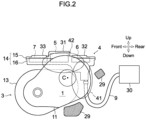
- the gearbox housing 13 of the present embodiment is arranged so as to be offset in the front-rear direction and downward from the left and right motor housings 11,12. Specifically, as shown in FIG. 2 , the positional relationship between the left motor housings 11, 12 and the gearbox housing 13 is set such that the gearbox 3 is displaced downward and forward of the vehicle on the basis of the rotating shafts C of the left motor 1 and the right motor 2 when seen from the side. Such a layout forms a depressed portion in a basin shape depressed in the front-rear direction and also downward between the left and right motor housings 11,12. As shown in FIG. 3 , in the vehicle drive device 10 of the present embodiment, the inverter 4 is disposed inside the depressed portion 8 by making use of the depressed portion 8.
- the inverter 4 is a converter (DC-AC inverter) that mutually converts the power (DC power) of a DC circuit and the power (AC power) of the AC circuits on the side of the motors 1,2.
- This inverter 4 has a function of converting DC power into AC power and supplying the converted AC power to both the left motor 1 and the right motor 2.
- An inverter case 14 is disposed above the left and right motor housings 11,12 (in the depressed portion 8 enclosed by the left and right motor housings 11,12 and the gearbox housing 13) and is fixed to the left and right motor housings 11,12.
- the inverter case 14 is formed by combining an invert
- first space 41 a space adjacent in the front-rear direction to the left and right motor housings 11,12 when seen from the side.
- second space 42 a space adjacent to the upper sides of the left and right motor housings 11,12 when viewed from the side.
- first space 41 and the second space 42 are indicated by the two-dot chain lines in FIG. 2 .
- the first space 41 is formed in such a shape (bulging shape) that the front side or the rear side thereof protrudes in the front-rear direction.
- second space 42 is formed in such a shape (bulging shape) that the lower side thereof protrudes downward.
- the inverter case 14 is arranged in the second space 42.
- the capacitor 5 is an electronic component that smooths electric power to be supplied to the motors 1,2.
- the capacitor 5 is disposed on an electricity supply line of AC power converted in the semiconductor modules 6,7.
- the capacitor 5 is disposed on an input side of DC power.
- the capacitor 5 functions as a kind of filter to stabilize the current supplied to the motors 1,2.
- the semiconductor modules 6, 7 are each a power module formed by forming a three-phase bridging circuit including multiple switching elements, diodes, and the like on a substrate (substrate for an electronic circuit). By intermittently switching the connecting states of the respective switching elements, the DC power is converted into three-phase AC power.
- the switching elements include semiconducting devices such as thyristors, IGBTs (Insulated Gate Bipolar Transistors), and power MOSFETs (Metal Oxide Semiconductor Field-Effect Transistors).
- the AC power generated by the left (one) semiconductor module 6 is supplied to the left motor 1, and the AC power generated by the right (the other) semiconductor module 7 is supplied to the right motor 2.
- a first bulging portion 31 having a shape bulging upward is formed at the center portion (center in the front-rear direction) of the inverter upper case 15.
- the capacitor 5 is mounted on the lower side and the inside of the first bulging portion 31, and is fixed so as to be suspended from the inverter upper case 15.
- a second bulging portion 32 is formed on the vehicle rear side of the first bulging portion 31 and a third bulging portion 33 is formed on the vehicle front side of the first bulging portion 31.
- the semiconductor modules 6,7 are mounted on the lower sides and the insides of the bulging portions 32,33, respectively and are fixed so as to be suspended from the inverter upper case 15.
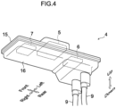
- the PN lines 9 for supplying electricity that connect the battery to the semiconductor modules 6,7 are connected from a lower surface side of the inverter case 14 so as to pass through the first space 41.
- the connecting point between each PN line 9 and the inverter case 14 is disposed in a space that is on the rear side of the gearbox housing 13 and that is sandwiched between the left and right motor housings 11,12.
- the PN line 9 is connected to a lower surface side of the inverter case 14 and is wired downward through a position on an opposite side to the gearbox housing 13 in the front-rear direction on the basis of the left and right motor housings 11,12.
- each PN line 9 extending from a junction box 30 is wired so as to avoid a suspension cross member 29 (suspension cross structural member).
- the junction box 30 is a device that relays the electric power from the battery and supplies it to the semiconductor modules 6,7 through the PN line 9, and is arranged on the rear side of the inverter case 14.
- the PN line 9 is connected to the rear portion of the lower surface side of the inverter case 14 and is connected to the junction box 30.
- a suspension cross member 29 is a member that supports the left and right wheels of the vehicle via a suspension.
- Gearbox housing 13 and the left and right motor housings 11, 12 are installed above (on top of) suspension cross member 29.
- Each PN line 9 is wired to pass above a lower end portion of the suspension cross member 29.
- connecting the PN line 9 to the lower surface side of the inverter case 14 efficiently uses the space in the depressed portion 8 and makes the entire shape of the vehicle drive device 10 compact.
- the PN lines 9 can be assembled from one direction on the rear side of the vehicle, the workability of connecting the PN lines 9 is greatly enhanced.
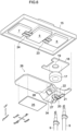
- FIGs. 5A-5C are three view drawings showing the internal structure of the inverter 4, and FIG. 6 is an exploded perspective view showing the inverter 4 from which the inverter lower case 16 is removed when seen obliquely upward from below.
- a ferrite core 17, a resin plate 18, multiple busbars 20, a control substrate 25, and a resin member 26 are provided in the inverter case 14.
- the ferrite core 17 is a component provided as a countermeasure against noise of the inverter 4 and is a ceramic-made magnetic material formed into an annular shape (doughnut shape).
- the ferrite core 17 is disposed under the left semiconductor module 6, and is partly arranged in the first space 41, for example.
- the resin plate 18 is a plate-shape member being made of resin and being arranged between the ferrite core 17 and the left semiconductor module 6, and is suspended from and fixed to the inverter case inverter upper case 15.
- a shield layer formed of a magnetic sheet that suppresses noise propagation is provided inside the resin plate 18. This structure makes the electromagnetic wave generated in, for example, the left semiconductor module 6 less propagate to the lower side of the resin plate 18 and consequently suppresses electromagnetic interference to a control substrate 25.
- the control substrate 25 is a control substrate of the semiconductor modules 6,7.
- Each busbar 20 is a conductor rod that efficiently transmits large electric current and is formed by bending rod- or plate-shaped metal member into a shape adaptable to the arrangement position.
- the busbar 20 is wired so as to pass through the interiors of the ferrite core 17 and the aperture 19.
- One end of the busbar 20 is connected to a PN line 9 at a position avoiding the ferrite core 17 when seen from below, as shown in FIGs. 5A to 5C and 6 .
- the other end of the busbar 20 is connected to semiconductor modules 6,7.
- the resin member 26 is a member that is made of resin and that holds the ferrite core 17, the busbars 20, and the control substrate 25 of the semiconductor modules 6,7.
- a box-shaped portion 34 located right under the ferrite core 17 has a shape more depressed downward than the remaining portion and forms steps on the front and rear side of the ferrite core 17.
- the control substrate 25 is fixed to the resin member 26 on the front side of the ferrite core 17, being suspended downward.
- the control substrate 25 is attached on the lower surface side opposite to the upper surface side where the semiconductor modules 6,7 are positioned among the plate surfaces of the resin member 26.
- a shield layer formed of a magnetic sheet that suppresses noise propagation is provided inside the resin member 26. This further suppresses electromagnetic interference to the control substrate 25.
- a through-hole 27 having a size corresponding to through-hole of the ferrite core 17 is provided.
- Each busbar 20 is provided so as to penetrate the interiors of the ferrite core 17 and the aperture 19 through the through-hole 27.
- an operation through-hole 28 is provided on the side surface on the vehicle front portion of the box-shaped portion 34.
- the operation through-hole 28 is an aperture through which a tool is inserted when a fastening member provided to a connecting point between a busbar 20 and the left semiconductor module 6 is to be fastened.
- Each busbar 20 illustrated in FIG. 6 includes a pair of first busbars 21, a pair of second busbars 22, a pair of third busbars 23, and a pair of fourth busbars 24.
- Each first bus bar 21 is connected to the corresponding PN line 9 via a fastening member and is arranged along the lower surface and the rear side surface of the box-shaped portion 34.
- Each second bus bar 22 is connected to the first bus bar 21 on the lower surface side of the box-shaped portion 34 and is connected to the left semiconductor module 6 through the through-hole of the ferrite core 17.
- the left semiconductor module 6 is connected to the PN lines 9 via the first busbars 21 and the second bus bars 22, and is supplied with the electric power of the battery.
- the busbars 20 are inserted into the inside of the annular-shaped ferrite core 17 from the lower part of the semiconductor modules 6,7 and are extended downward, and are extended toward the rear side of the ferrite core 17 in a posture along the plate surface of the resin member 26.
- Each third bus bar 23 has one end co-fastened to the left semiconductor module 6 together via the fastening member and the other end connected to the capacitor 5.
- Each fourth bus bar 24 has one end connected to the right semiconductor module 7 and the other end connected to the capacitor 5. Inside the capacitor 5, the third bus bar 23 and the fourth bus bar 24 are electrically connected.
- the right semiconductor module 7 is connected to the PN lines 9 via the capacitor 5 as well as the busbars 21-24 and is supplied with the electric power of the battery.
- the PN lines 9 extending from the junction box 30 are connected from the lower surface side of the inverter case 14 so as to pass through the first space 41.
- This structure can reduce the sizes in the front-rear direction and the up-down direction of the inverter 4, for example, as compared with a structure that the PN lines 9 are connected to the upper surface or the rear surface of the inverter case 14, therefore the entire shape of the inverter 4 can be made compact.
- the space on the rear side of the gearbox housing 13 can be efficiently used, thus size reduction of the vehicle drive device 10 can be accomplished.
- the protectability for the PN lines 9 can be enhanced because the circumference of the PN lines 9 is enclosed by the left and right motor housings11,12, and the gearbox housing 13. Furthermore, since the PN lines 9 can be assembled from one direction on the rear side of the vehicle, the workability of connecting the PN lines 9 is greatly enhanced. Therefore, the vehicle drive device 10 described above can enhance the vehicle mountability with a simple structure.
- the PN lines 9 are wired to pass above a lower end portion of the suspension cross member 29.
- the PN lines 9 can be wired without hindering the suspension function, and the circumference of the PN lines 9 can be protected by the suspension cross member 29.
- the PN lines 9 are connected to the rear portion of the lower surface side of the inverter case 14 and is connected to the junction box 30.
- the junction box 30 is arranged at a position relatively close to the rear side of the inverter case 14.
- the PN lines 9 are connected to the inverter case 14 at positions avoiding the ferrite core 17.
- This structure can connect the PN lines 9 to the busbars 20 at a position of approximately the same height as the ferrite core 17, so that the overall PN lines 9 can be positioned upward.
- PN lines 9 can be wired without difficulty. Therefore, it is possible to enhance the degree of freedom in the layout of the PN lines 9, the vehicle drive device 10, and various devices (for example, the suspension cross member 29 and the junction box 30) arranged in the vicinity thereof.
- the ferrite core 17 is disposed under the left semiconductor module 6.
- the size in the vehicle front-rear direction of the inverter 4 can be reduced. Accordingly, the vehicle mountability of the vehicle drive device 10 can be improved with a simple configuration. Further, since the ferrite core 17 does not largely protrude to the outside of the inverter 4, the size of entire device can be reduced, and the vehicle mountability of the vehicle drive device 10 can be further enhanced.
- the PN line 9 that connect the battery and the busbar 20 to each other is connected to the lower surface side of inverter case 14.
- This structure can reduce the dimensions in the front-rear direction and the up-down direction of the inverter 4 as compared with a structure that the PN line 9 is connected to the upper surface or the rear surface of the inverter case 14, therefore the entire shape of the inverter 4 can be made compact.
- the PN line 9 can be assembled from one direction on the rear side of the vehicle, the workability of connecting the PN line 9 is greatly enhanced.
- the gearbox housing 13 is disposed so as to be offset in the front-rear direction with respect to the left and right motor housings 11,12.
- the PN line 9 is connected to the lower surface side of the inverter case 14 so as to pass through the first space 41 surrounded by the motor housings 11,12 and the gearbox housing 13.
- the ferrite core 17 is at least partly arranged in the first space 41. As described above, by partly arranging the ferrite core 17 in the first space 41, the circumference of the ferrite core 17 can be enclosed by the left and right motor housings 11,12 and the gearbox housing 13 so that the protectability of the ferrite core 17 can be enhanced. In addition, the protectability for the PN line 9 can be enhanced because the circumference of the PN line is enclosed by the left and right motor housings 11,12, and the gearbox housing 13.
- the resin plate 18 is disposed between the left semiconductor module 6 and the ferrite core 17 and is fixed to and suspended from the inverter upper case 15.
- the propagation of the electromagnetic wave generated in the left semiconductor module 6 can be suppressed, and the electromagnetic interference to the ferrite core 17 and control substrate 25 can be suppressed.
- the heat generated in the left semiconductor module 6 is hardly diffused to the lower side of the resin plate 18, therefore performance deterioration and degradation of the ferrite core 17 and the control substrate 25 can be suppressed.
- the resin plate 18 incorporates therein the shield layer. This can further reduce propagation of the electromagnetic wave to the lower side of the resin plate18 and the effect of suppressing electromagnetic interference can be further enhanced. Further, since electromagnetic interference to the control substrate 25 is suppressed, it is possible to stably operate the control substrate 25 and to maintain fine performance of the vehicle drive device 10. Since as well as the resin plate 18, the resin member 26 incorporates therein a shield layer, the electromagnetic wave which may act on the control substrate 25 can be reliably weakened and the performance of vehicle drive device 10 can be more reliably maintained.
- the busbar 20 is inserted from the lower part of the semiconductor modules 6,7 into the interior of the annular-shaped ferrite core 17 and extends downward, and extends toward the rear side of the ferrite core 17.
- PN line 9 is connected to the busbar 20 at a position avoiding the ferrite core 17 when seen from below.
- This structure can connect the PN line 9 to the busbar 20 at a position of approximately the same height as the ferrite core 17, so that the overall PN 9 can be positioned upward.
- PN line 9 can be wired without difficulty. Therefore, it is possible to enhance the degree of freedom in the layout of the PN lines 9, the vehicle drive device 10, and various devices (for example, the suspension cross member 29 and the junction box 30) arranged in the vicinity thereof.
- the above embodiment illustrates the vehicle drive device 10 that arranges the gearbox 3 offset downward and forward of the vehicle on the basis of the rotating shafts C of the motors 1,2 when seen from the side.
- the gearbox 3 may be offset downward and rearward of the vehicle. At least, by offsetting the gearbox housing 13 downward from the left and right motor housings 11,12, arrangement of the inverter case 14 using the depressed portion 8 is facilitated and the PN lines 9 are easily connected to the lower surface side of the inverter case 14. Therefore, this alternative can achieve the same actions and effects as those of the above embodiment.
- FIG. 7 is an exploded perspective view illustrating the internal structure of the inverter 4 according to a modification.
- the resin plate 40 shown in FIG. 7 is a plate-like member having both the function of the resin plate 18 and the function of the resin member 26 in the above-described embodiment.
- the resin plate 40 holds the ferrite core 17, the busbars 20, and the control substrate 25 of the semiconductor module 6,7.
- the resin plate 40 is provided projectingly with multiple claw members 41 to lock the ferrite core 17. These claw members 41 allow the ferrite core 17 to be suspended from and fixed to the lower surface of resin plate 40.
- the resin plate 40 and the ferrite core 17 may be integrated with each other.
- the aperture 42 is provided, for example, at a position facing a connecting point between busbars 20 and the left semiconductor module 6.
- the busbar 20 illustrated in FIG. 7 includes a pair of first busbars 21, a pair of second busbars 22, a pair of third busbars 23, and a pair of fourth busbars 24.
- the third busbars 23 and the fourth busbars 24 are almost the same as those of the above embodiment, the first busbars 21 and the second busbars 22 are different from those of the above embodiment.
- Each first busbar 21 is connected to the corresponding PN line 9 via a fastening member and is arranged so as to pass through a gap between the resin plate 40 and the ferrite core 17.
- Each second busbar 22 is connected to the corresponding first busbar 21 inside the gap, guided to the lower side of the ferrite core 17 through the through-hole of the ferrite core 17, and connected to the left semiconductor module 6 through the aperture 42.
- the control substrate 25 is downward suspended from and fixed to the resin plate 40 on the front side of the ferrite core 17.
- the position of the control substrate 25 is set, for example, under the capacitor 5 or the right semiconductor module 7.
- the control substrate 25 is arranged on the lower surface side opposite to the upper surface side where the semiconductor modules 6,7 are positioned among the plate surfaces of the resin plate 40.
- a shield layer formed of a magnetic sheet that suppresses noise propagation is provided inside the resin plate 40.
- the shield layer is formed at least on the upper side of the ferrite core 17 and the upper side of the control substrate 25, and are preferably formed over the entire resin plate 40.
- a vehicle drive device including:
- the vehicle drive device according to appendix 1 or 2, further including a resin plate that is arranged between the semiconductor module and the ferrite core and that is suspended from and fixed to the inverter case.
- the vehicle drive device wherein the resin plate holds the ferrite core, the busbar, and a control substrate of the semiconductor module.
- control substrate is attached on an opposite plate surface of the resin plate to the semiconductor module.
- the vehicle drive device according to any one of appendices 3-5, wherein the resin plate incorporates therein a shield layer.
- the vehicle drive device according to any one of appendices 3-6, wherein the resin plate is integrated with the ferrite core.
Landscapes
- Engineering & Computer Science (AREA)
- Power Engineering (AREA)
- Mechanical Engineering (AREA)
- Transportation (AREA)
- Sustainable Development (AREA)
- Life Sciences & Earth Sciences (AREA)
- Sustainable Energy (AREA)
- Chemical & Material Sciences (AREA)
- Combustion & Propulsion (AREA)
- Physics & Mathematics (AREA)
- Electromagnetism (AREA)
- Microelectronics & Electronic Packaging (AREA)
- Electric Propulsion And Braking For Vehicles (AREA)
Abstract
Description
- The present disclosure relates to a vehicle drive device that drives left and right wheels of a vehicle using electricity of a battery.
- Conventionally, vehicle drive devices have been known which drive left and right wheels of the vehicle with two motors (electric motors). For example, one of the proposed vehicle drive devices connects motors one to each of the left and the right wheels so that the left and the right wheels can be driven independently from each other. Such a vehicle drive device can generate a rotational speed difference and a torque difference between the left and the right wheels by making the driving forces of the left and the right motors different from each other. This improves the turning performance of the vehicle and the stability of the vehicle body while turning (see Patent Document 1).
- [Patent Document 1]
Japanese Laid-open Patent Publication No. 2017-184523 - In the vehicle drive device as described above, an inverter for controlling the rotating state of the AC motor is incorporated. The DC power of a battery mounted on a vehicle is converted into AC power by the inverter and then supplied to left and right motors. In addition, a PN line (power supply line), through which electricity to be supplied from the battery to the inverter flows, is inserted from, for example, the upper surface or the back surface of the inverter and fastened and fixed to a busbar inside the inverter. This structure tends to increase the size in the vehicle front-rear direction of the inverter and makes it difficult to enhance the mountability of a vehicle. In addition, if a suspension device or another structure (for example, a suspension cross member or a stabilizer) is disposed around the vehicle drive device, the PN line may be unable to be connected to the upper surface or the back surface of the inverter due to a constraint of the layout.
- The power supply line (PN line) from the battery to the inverter may be inserted into the inverter from the upper surface or the rear surface of the inverter, being inserted into a ferrite core, which is provided as a countermeasure against noise, and then may be fastened and fixed to the busbar in the inverter. This structure, for example, easily increases the size in the vehicle front-rear direction of the inverter and therefore has difficulty in enhancing the mountability of the vehicle. In addition, if the ferrite core is provided so as to largely protrude to the outside of the inverter, it is difficult to reduce the size of the entire device, and the vehicle mountability may be deteriorated.
- With the foregoing problems in view, one of the objects of the present disclosure is to provide a vehicle drive device capable of enhancing the vehicle mountability with a simple structure. In addition to this object, actions and effects which are derived from each configuration of an embodiment to carry out the invention to be described below and which conventional technique does not attain can be set as other objects of the present disclosure.
- The disclosed vehicle drive device includes: left and right motor housings that form respective exteriors of left and right motors, the left and right motors driving left and right wheels of a vehicle with electric power of a battery; a gearbox housing that incorporates therein a gearbox, that is sandwiched between the left and right motor housings, and that is offset in a front-rear direction from the left and right motor housings, the gearbox amplifying torque of the left and right motors and transmitting the amplified torque to the left and right wheels; an inverter case that incorporates therein a pair of semiconductor modules and that is arranged above the left and right motor housings, the pair of semiconductor modules converting direct current to alternating current and supplying the alternating current to the left and right motors; and a PN line that connects the battery to the semiconductor modules from a lower surface side of the inverter case so as to pass through a first space bulging in a front-rear direction, the first space being enclosed by the left and right motor housings and the gearbox housing.
- The vehicle drive device disclosed herein can enhance the mountability of a vehicle with a simple structure.
-
-
FIG. 1 is an exploded perspective view of a vehicle drive device according to an embodiment; -
FIG. 2 is a left side view of the vehicle drive device ofFIG. 1 ; -
FIG. 3 is a sectional view illustrating an internal structure of the vehicle drive device ofFIG. 1 ; -
FIG. 4 is a perspective view illustrating an inverter of the vehicle drive device ofFIG. 1 ; -
FIGs. 5A to 5C are three view drawings of the inverter ofFIG. 4 ; -
FIG. 6 is an exploded perspective view illustrating an internal structure of the inverter ofFIG. 4 ; and -
FIG. 7 is an exploded perspective view illustrating an internal structure of an inverter according to a modification. -
FIG. 1 to FIG. 7 are diagrams for explaining the structure of avehicle drive device 10 according to the present embodiment and a modification. The front-rear, left-right, and up-down directions in the drawings represent directions determined with reference to the driver of a vehicle on whichvehicle drive device 10 is mounted. As shown inFIG. 1 , thevehicle drive device 10 is provided with aleft motor 1, aright motor 2, agearbox 3, and aninverter 4. Theleft motor 1 and theright motor 2 are electric motors that receive electric power from a battery mounted on the vehicle and drive left and right wheels of the vehicle. - The
left motor 1 is connected to a power transmission path connected to at least the left wheel shaft. Similarly, theright motor 2 is connected to a power transmission path connected to at least the right wheel shaft. In an electric vehicle or a hybrid vehicle mounted thereon another driving motor or an internal combustion engine, theleft motor 1 and theright motor 2 function as a yaw moment generating source that generates turning force by increasing or decreasing at least driving force and braking force of left and right wheels. Further, in an electric vehicle not mounted thereon any other driving motor, themotors - Each of the
left motor 1 and theright motor 2 has a configuration incorporating therein motor elements such as a stator, a rotor, and a motor shaft. These elements are accommodated in left andright motor housings 11,12 (left motor housing 11, right motor housing 12) that form the exteriors of therespective motors FIG. 3 . The stator is a stator which has a structure, for example, that winds a coil around a laminated iron core formed by depositing insulating steel sheets and is fixed to thecorresponding motor housing gearbox 3. - The
gearbox 3 is a driving force transmission device sandwiched between the left and theright motor housings gearbox 3 includes agearbox housing 13 that forms an exterior and a gear mechanism incorporated therein. The gear mechanism is a mechanism that amplifies the torques of theleft motor 1 and theright motor 2 and transmits amplified torques to the left and the right wheels. In addition, the gear mechanism includes a mechanism (e.g., a differential gear mechanism, a planetary gear mechanism) for generating a torque difference between the left wheel shaft and the right wheel shaft. - The gearbox housing 13 of the present embodiment is arranged so as to be offset in the front-rear direction and downward from the left and
right motor housings FIG. 2 , the positional relationship between theleft motor housings gearbox housing 13 is set such that thegearbox 3 is displaced downward and forward of the vehicle on the basis of the rotating shafts C of theleft motor 1 and theright motor 2 when seen from the side. Such a layout forms a depressed portion in a basin shape depressed in the front-rear direction and also downward between the left andright motor housings FIG. 3 , in thevehicle drive device 10 of the present embodiment, theinverter 4 is disposed inside thedepressed portion 8 by making use of thedepressed portion 8. - The
inverter 4 is a converter (DC-AC inverter) that mutually converts the power (DC power) of a DC circuit and the power (AC power) of the AC circuits on the side of themotors inverter 4 has a function of converting DC power into AC power and supplying the converted AC power to both theleft motor 1 and theright motor 2. Inside aninverter case 14, which forms the exterior of theinverter 4, acapacitor 5 and a pair ofsemiconductor modules 6, 7 (left semiconductor module 6 and right semiconductor module 7) are provided. Aninverter case 14 is disposed above the left andright motor housings 11,12 (in thedepressed portion 8 enclosed by the left andright motor housings right motor housings inverter case 14 is formed by combining an inverterupper case 15 having a shape covering the upper surface sides of thecapacitor 5 and thesemiconductor modules lower case 16 having a shape covering the lower surface side. - Here, among the
depressed portion 8, a space adjacent in the front-rear direction to the left andright motor housings first space 41. Among the space enclosed by the left andright motor housings gearbox housing 13, a space adjacent to the upper sides of the left andright motor housings second space 42. Thesefirst space 41 and thesecond space 42 are indicated by the two-dot chain lines inFIG. 2 . Thefirst space 41 is formed in such a shape (bulging shape) that the front side or the rear side thereof protrudes in the front-rear direction. In addition, thesecond space 42 is formed in such a shape (bulging shape) that the lower side thereof protrudes downward. Theinverter case 14 is arranged in thesecond space 42. - The
capacitor 5 is an electronic component that smooths electric power to be supplied to themotors capacitor 5 is disposed on an electricity supply line of AC power converted in thesemiconductor modules capacitor 5 is disposed on an input side of DC power. Thecapacitor 5 functions as a kind of filter to stabilize the current supplied to themotors - The
semiconductor modules semiconductor module 6 is supplied to theleft motor 1, and the AC power generated by the right (the other)semiconductor module 7 is supplied to theright motor 2. - As shown in
FIGs. 1 and2 , a first bulgingportion 31 having a shape bulging upward is formed at the center portion (center in the front-rear direction) of the inverterupper case 15. Thecapacitor 5 is mounted on the lower side and the inside of the first bulgingportion 31, and is fixed so as to be suspended from the inverterupper case 15. Further, a second bulgingportion 32 is formed on the vehicle rear side of the first bulgingportion 31 and a third bulgingportion 33 is formed on the vehicle front side of the first bulgingportion 31. Like thecapacitor 5, thesemiconductor modules portions upper case 15. - As shown in
FIGs. 2 and4 , thePN lines 9 for supplying electricity that connect the battery to thesemiconductor modules inverter case 14 so as to pass through thefirst space 41. The connecting point between eachPN line 9 and theinverter case 14 is disposed in a space that is on the rear side of thegearbox housing 13 and that is sandwiched between the left andright motor housings PN line 9 is connected to a lower surface side of theinverter case 14 and is wired downward through a position on an opposite side to thegearbox housing 13 in the front-rear direction on the basis of the left andright motor housings - In the present embodiment, as shown in
FIG. 2 , eachPN line 9 extending from ajunction box 30 is wired so as to avoid a suspension cross member 29 (suspension cross structural member). Thejunction box 30 is a device that relays the electric power from the battery and supplies it to thesemiconductor modules PN line 9, and is arranged on the rear side of theinverter case 14. ThePN line 9 is connected to the rear portion of the lower surface side of theinverter case 14 and is connected to thejunction box 30. - A
suspension cross member 29 is a member that supports the left and right wheels of the vehicle via a suspension.Gearbox housing 13 and the left andright motor housings suspension cross member 29. EachPN line 9 is wired to pass above a lower end portion of thesuspension cross member 29. As described above, connecting thePN line 9 to the lower surface side of theinverter case 14 efficiently uses the space in thedepressed portion 8 and makes the entire shape of thevehicle drive device 10 compact. In addition, since thePN lines 9 can be assembled from one direction on the rear side of the vehicle, the workability of connecting thePN lines 9 is greatly enhanced. -
FIGs. 5A-5C are three view drawings showing the internal structure of theinverter 4, andFIG. 6 is an exploded perspective view showing theinverter 4 from which the inverterlower case 16 is removed when seen obliquely upward from below. In theinverter case 14, aferrite core 17, aresin plate 18,multiple busbars 20, acontrol substrate 25, and aresin member 26 are provided. Theferrite core 17 is a component provided as a countermeasure against noise of theinverter 4 and is a ceramic-made magnetic material formed into an annular shape (doughnut shape). As illustrated inFIGs. 5B and 5C , theferrite core 17 is disposed under theleft semiconductor module 6, and is partly arranged in thefirst space 41, for example. - The
resin plate 18 is a plate-shape member being made of resin and being arranged between theferrite core 17 and theleft semiconductor module 6, and is suspended from and fixed to the inverter case inverterupper case 15. On theresin plate 18, anaperture 19 having a size corresponding to the through-hole of theferrite core 17. In addition, inside theresin plate 18, a shield layer formed of a magnetic sheet that suppresses noise propagation is provided. This structure makes the electromagnetic wave generated in, for example, theleft semiconductor module 6 less propagate to the lower side of theresin plate 18 and consequently suppresses electromagnetic interference to acontrol substrate 25. Thecontrol substrate 25 is a control substrate of thesemiconductor modules - Each
busbar 20 is a conductor rod that efficiently transmits large electric current and is formed by bending rod- or plate-shaped metal member into a shape adaptable to the arrangement position. Thebusbar 20 is wired so as to pass through the interiors of theferrite core 17 and theaperture 19. One end of thebusbar 20 is connected to aPN line 9 at a position avoiding theferrite core 17 when seen from below, as shown inFIGs. 5A to 5C and6 . The other end of thebusbar 20 is connected tosemiconductor modules - The
resin member 26 is a member that is made of resin and that holds theferrite core 17, thebusbars 20, and thecontrol substrate 25 of thesemiconductor modules FIG. 6 , a box-shapedportion 34 located right under theferrite core 17 has a shape more depressed downward than the remaining portion and forms steps on the front and rear side of theferrite core 17. Using these steps, thecontrol substrate 25 is fixed to theresin member 26 on the front side of theferrite core 17, being suspended downward. Thecontrol substrate 25 is attached on the lower surface side opposite to the upper surface side where thesemiconductor modules resin member 26. In addition, like theresin plate 18, a shield layer formed of a magnetic sheet that suppresses noise propagation is provided inside theresin member 26. This further suppresses electromagnetic interference to thecontrol substrate 25. - On the lower surface of the box-shaped
portion 34, a through-hole 27 having a size corresponding to through-hole of theferrite core 17 is provided. Eachbusbar 20 is provided so as to penetrate the interiors of theferrite core 17 and theaperture 19 through the through-hole 27. In addition, an operation through-hole 28 is provided on the side surface on the vehicle front portion of the box-shapedportion 34. The operation through-hole 28 is an aperture through which a tool is inserted when a fastening member provided to a connecting point between abusbar 20 and theleft semiconductor module 6 is to be fastened. - Each
busbar 20 illustrated inFIG. 6 includes a pair offirst busbars 21, a pair ofsecond busbars 22, a pair ofthird busbars 23, and a pair offourth busbars 24. Eachfirst bus bar 21 is connected to the correspondingPN line 9 via a fastening member and is arranged along the lower surface and the rear side surface of the box-shapedportion 34. Eachsecond bus bar 22 is connected to thefirst bus bar 21 on the lower surface side of the box-shapedportion 34 and is connected to theleft semiconductor module 6 through the through-hole of theferrite core 17. Theleft semiconductor module 6 is connected to thePN lines 9 via thefirst busbars 21 and the second bus bars 22, and is supplied with the electric power of the battery. As the above, thebusbars 20 are inserted into the inside of the annular-shapedferrite core 17 from the lower part of thesemiconductor modules ferrite core 17 in a posture along the plate surface of theresin member 26. - Each
third bus bar 23 has one end co-fastened to theleft semiconductor module 6 together via the fastening member and the other end connected to thecapacitor 5. Eachfourth bus bar 24 has one end connected to theright semiconductor module 7 and the other end connected to thecapacitor 5. Inside thecapacitor 5, thethird bus bar 23 and thefourth bus bar 24 are electrically connected. Theright semiconductor module 7 is connected to thePN lines 9 via thecapacitor 5 as well as the busbars 21-24 and is supplied with the electric power of the battery. - (A-1) In the
vehicle drive device 10 described above, as shown inFIG. 2 , thePN lines 9 extending from thejunction box 30 are connected from the lower surface side of theinverter case 14 so as to pass through thefirst space 41. This structure can reduce the sizes in the front-rear direction and the up-down direction of theinverter 4, for example, as compared with a structure that thePN lines 9 are connected to the upper surface or the rear surface of theinverter case 14, therefore the entire shape of theinverter 4 can be made compact. Furthermore, among thedepressed portion 8, the space on the rear side of thegearbox housing 13 can be efficiently used, thus size reduction of thevehicle drive device 10 can be accomplished. In addition, the protectability for thePN lines 9 can be enhanced because the circumference of thePN lines 9 is enclosed by the left and right motor housings11,12, and thegearbox housing 13. Furthermore, since thePN lines 9 can be assembled from one direction on the rear side of the vehicle, the workability of connecting thePN lines 9 is greatly enhanced. Therefore, thevehicle drive device 10 described above can enhance the vehicle mountability with a simple structure. - (A-2) In the
vehicle drive device 10 described above, as shown inFIG. 2 , thegearbox housing 13 is offset downward from the left andright motor housings inverter case 14 is disposed in thesecond space 42 bulging downward. This makes it possible to reduce the size in the up-down direction of thevehicle drive device 10. Further, eachPN line 9 connected to the lower surface side of theinverter case 14 is wired downward through a position on an opposite side to thegearbox housing 13 in the front-rear direction with respect to the left andright motor housings FIG. 2 ) and size reduction of thevehicle drive device 10 can be accomplished. - (A-3) In the
vehicle drive device 10 described above, thePN lines 9 are wired to pass above a lower end portion of thesuspension cross member 29. With this structure, thePN lines 9 can be wired without hindering the suspension function, and the circumference of thePN lines 9 can be protected by thesuspension cross member 29. - (A-4) In the
vehicle drive device 10 described above, thePN lines 9 are connected to the rear portion of the lower surface side of theinverter case 14 and is connected to thejunction box 30. Thejunction box 30 is arranged at a position relatively close to the rear side of theinverter case 14. With such a structure, the wiring layout of thePN lines 9 can be simplified while the interference betweenPN lines 9 and the peripheral structures is avoided, therefore the workability of connecting of thePN lines 9 can be enhanced. - (A-5) In the
vehicle drive device 10 described above, as shown inFIG. 5C , thePN lines 9 are connected to theinverter case 14 at positions avoiding theferrite core 17. This structure can connect thePN lines 9 to thebusbars 20 at a position of approximately the same height as theferrite core 17, so that theoverall PN lines 9 can be positioned upward. For example, even when an interfering object (the suspension cross member 29) is present below thevehicle drive device 10 as shown inFIG. 2 ,PN lines 9 can be wired without difficulty. Therefore, it is possible to enhance the degree of freedom in the layout of thePN lines 9, thevehicle drive device 10, and various devices (for example, thesuspension cross member 29 and the junction box 30) arranged in the vicinity thereof. - (B-1) In the
vehicle drive device 10 described above, as shown inFIG. 5B , theferrite core 17 is disposed under theleft semiconductor module 6. With such a structure, for example, comparing with a structure in which theferrite core 17 is provided outside of theinverter case 14, the size in the vehicle front-rear direction of theinverter 4 can be reduced. Accordingly, the vehicle mountability of thevehicle drive device 10 can be improved with a simple configuration. Further, since theferrite core 17 does not largely protrude to the outside of theinverter 4, the size of entire device can be reduced, and the vehicle mountability of thevehicle drive device 10 can be further enhanced. - In the
vehicle drive device 10 described above, thePN line 9 that connect the battery and thebusbar 20 to each other is connected to the lower surface side ofinverter case 14. This structure can reduce the dimensions in the front-rear direction and the up-down direction of theinverter 4 as compared with a structure that thePN line 9 is connected to the upper surface or the rear surface of theinverter case 14, therefore the entire shape of theinverter 4 can be made compact. Furthermore, since thePN line 9 can be assembled from one direction on the rear side of the vehicle, the workability of connecting thePN line 9 is greatly enhanced. - (B-2) In the
vehicle drive device 10 described above, thegearbox housing 13 is disposed so as to be offset in the front-rear direction with respect to the left andright motor housings PN line 9 is connected to the lower surface side of theinverter case 14 so as to pass through thefirst space 41 surrounded by themotor housings gearbox housing 13. Further, theferrite core 17 is at least partly arranged in thefirst space 41. As described above, by partly arranging theferrite core 17 in thefirst space 41, the circumference of theferrite core 17 can be enclosed by the left andright motor housings gearbox housing 13 so that the protectability of theferrite core 17 can be enhanced. In addition, the protectability for thePN line 9 can be enhanced because the circumference of the PN line is enclosed by the left andright motor housings gearbox housing 13. - (B-3) In the
vehicle drive device 10 described above, theresin plate 18 is disposed between theleft semiconductor module 6 and theferrite core 17 and is fixed to and suspended from the inverterupper case 15. Thus, the propagation of the electromagnetic wave generated in theleft semiconductor module 6 can be suppressed, and the electromagnetic interference to theferrite core 17 andcontrol substrate 25 can be suppressed. Further, the heat generated in theleft semiconductor module 6 is hardly diffused to the lower side of theresin plate 18, therefore performance deterioration and degradation of theferrite core 17 and thecontrol substrate 25 can be suppressed. - (B-4) In the
vehicle drive device 10 described above, theresin plate 18 incorporates therein the shield layer. This can further reduce propagation of the electromagnetic wave to the lower side of the resin plate18 and the effect of suppressing electromagnetic interference can be further enhanced. Further, since electromagnetic interference to thecontrol substrate 25 is suppressed, it is possible to stably operate thecontrol substrate 25 and to maintain fine performance of thevehicle drive device 10. Since as well as theresin plate 18, theresin member 26 incorporates therein a shield layer, the electromagnetic wave which may act on thecontrol substrate 25 can be reliably weakened and the performance ofvehicle drive device 10 can be more reliably maintained. - (B-5) In the
vehicle drive device 10 described above, thebusbar 20 is inserted from the lower part of thesemiconductor modules ferrite core 17 and extends downward, and extends toward the rear side of theferrite core 17. In addition,PN line 9 is connected to thebusbar 20 at a position avoiding theferrite core 17 when seen from below. This structure can connect thePN line 9 to thebusbar 20 at a position of approximately the same height as theferrite core 17, so that theoverall PN 9 can be positioned upward. For example, even when an interferer (suspension cross member 29) exists belowvehicle drive device 10 as shown inFIG. 2 ,PN line 9 can be wired without difficulty. Therefore, it is possible to enhance the degree of freedom in the layout of thePN lines 9, thevehicle drive device 10, and various devices (for example, thesuspension cross member 29 and the junction box 30) arranged in the vicinity thereof. - (B-6) In the
vehicle drive device 10 described above, as shown inFIG. 6 , theright semiconductor module 7 is connected to thePN lines 9 via thebusbar 20 and thecapacitor 5. As described above, by providing thecapacitor 5 with the similar power supply function as thebusbar 20, it is possible to omit the busbar to connect the left andright semiconductor modules inverter case 14 can be simplified, and the size and the weight of thevehicle drive device 10 can be further reduced. - The foregoing embodiment is illustrative only and is not intended to preclude the application of various modifications and techniques not explicitly set forth in the present examples. Each configuration of the present embodiment can be variously modified and implemented without departing from the scope thereof. In addition, the configurations of the present embodiment can be selected and omitted as needed, or can be combined appropriately.
- For example, the above embodiment illustrates the
vehicle drive device 10 that arranges thegearbox 3 offset downward and forward of the vehicle on the basis of the rotating shafts C of themotors gearbox 3 may be offset downward and rearward of the vehicle. At least, by offsetting thegearbox housing 13 downward from the left andright motor housings inverter case 14 using thedepressed portion 8 is facilitated and thePN lines 9 are easily connected to the lower surface side of theinverter case 14. Therefore, this alternative can achieve the same actions and effects as those of the above embodiment. -
FIG. 7 is an exploded perspective view illustrating the internal structure of theinverter 4 according to a modification. Theresin plate 40 shown inFIG. 7 is a plate-like member having both the function of theresin plate 18 and the function of theresin member 26 in the above-described embodiment. Theresin plate 40 holds theferrite core 17, thebusbars 20, and thecontrol substrate 25 of thesemiconductor module resin plate 40 is provided projectingly withmultiple claw members 41 to lock theferrite core 17. Theseclaw members 41 allow theferrite core 17 to be suspended from and fixed to the lower surface ofresin plate 40. Theresin plate 40 and theferrite core 17 may be integrated with each other. In addition, anaperture 42 through which thebusbars 20 is formed in the vicinity of a point where theferrite core 17 is attached. Theaperture 42 is provided, for example, at a position facing a connecting point betweenbusbars 20 and theleft semiconductor module 6. - The
busbar 20 illustrated inFIG. 7 includes a pair offirst busbars 21, a pair ofsecond busbars 22, a pair ofthird busbars 23, and a pair offourth busbars 24. Although thethird busbars 23 and thefourth busbars 24 are almost the same as those of the above embodiment, thefirst busbars 21 and thesecond busbars 22 are different from those of the above embodiment. Eachfirst busbar 21 is connected to the correspondingPN line 9 via a fastening member and is arranged so as to pass through a gap between theresin plate 40 and theferrite core 17. Eachsecond busbar 22 is connected to the correspondingfirst busbar 21 inside the gap, guided to the lower side of theferrite core 17 through the through-hole of theferrite core 17, and connected to theleft semiconductor module 6 through theaperture 42. - The
control substrate 25 is downward suspended from and fixed to theresin plate 40 on the front side of theferrite core 17. The position of thecontrol substrate 25 is set, for example, under thecapacitor 5 or theright semiconductor module 7. Furthermore, thecontrol substrate 25 is arranged on the lower surface side opposite to the upper surface side where thesemiconductor modules resin plate 40. Inside theresin plate 40, a shield layer formed of a magnetic sheet that suppresses noise propagation is provided. The shield layer is formed at least on the upper side of theferrite core 17 and the upper side of thecontrol substrate 25, and are preferably formed over theentire resin plate 40. - (1) In the above modification, the
ferrite core 17, thebusbar 20, and thecontrol substrate 25 are held byresin plate 40. Accordingly, multiple components (theferrite core 17, thebusbar 20, the control substrate 25) can be fixed to theresin plate 40 with a simple structure. For example, comparing with a case where a holding member that holds theferrite core 17 and a holding member that holds thecontrol substrate 25 are separately provided, this modification can reduce the number of components. Furthermore, the number of fastening points (the number of screws) for fixing such multiple holding members to the inverterupper case 15 and the number of operation steps required for the fastening can be reduced. - (2) Further, in the above modification, the
control substrate 25 is arranged on an opposite side (lower surface side) of theresin plate 40 to the side where thesemiconductor modules control substrate 25 from thesemiconductor modules control substrate 25 due to heat generating of thesemiconductor modules - (3) If the
resin plate 40 is integrally formed with theferrite core 17, the number of components can be reduced, and the number of operation steps required for assembling theinverter 4 can be reduced. - A vehicle drive device including:
- left and right motor housings that form respective exteriors of left and right motors, the left and right motors driving left and right wheels of a vehicle with electric power of a battery;
- a gearbox housing that incorporates therein a gearbox, that is sandwiched between the left and right motor housings, and that is offset downward from the left and right motor housings, the gearbox amplifying torque of the left and right motors and transmitting the amplified torque to the left and right wheels;
- an inverter case that incorporates therein a pair of semiconductor modules and an annular ferrite core through which a busbar is inserted, the inverter case being arranged in a depressed portion enclosed by the left and right motor housings and the gearbox housing, the pair of semiconductor modules converting direct current to alternating current and supplying the alternating current to the left and right motors, the busbar supplying electric power to the semiconductor modules; and
- a PN line that connects the battery to the busbar and that is connected to a lower face side of the inverter case, wherein
- the ferrite core is arranged below the semiconductor modules.
- The vehicle drive device according to
appendix 1, wherein - the gearbox housing is offset in a front-rear direction from the left and right motor housings,
- the PN line is connected to the lower surface side of the inverter case so as to pass through a first space in a bulging shape in a front-rear direction, the first space being enclosed by the left and right motor housings and the gearbox housing, and
- the ferrite core is at least partly arranged in the first space.
- The vehicle drive device according to
appendix
a resin plate that is arranged between the semiconductor module and the ferrite core and that is suspended from and fixed to the inverter case. - The vehicle drive device according to
appendix 3, wherein
the resin plate holds the ferrite core, the busbar, and a control substrate of the semiconductor module. - The vehicle drive device according to
appendix 4, wherein
the control substrate is attached on an opposite plate surface of the resin plate to the semiconductor module. - The vehicle drive device according to any one of appendices 3-5, wherein
the resin plate incorporates therein a shield layer. - The vehicle drive device according to any one of appendices 3-6, wherein
the resin plate is integrated with the ferrite core. - The vehicle drive device according to any one of appendices 1-7, wherein
- the busbar is extended downward from a lower portion of the semiconductor module, passing through an interior of the ferrite core, and is extended rearward of the ferrite core, and
- the PN line is connected to a busbar at a position avoiding the ferrite core when seen from below.
- The vehicle drive device according to any one of appendices 1-8, wherein
- the inverter case incorporates therein a capacitor,
- the pair of semiconductor modules are arranged so as to sandwich the capacitor in the front-read direction, and
- a first one of the pair of semiconductor modules is connected to the PN line via the busbar and a second one of the pair of semiconductor modules is connected to the PN line via the busbar and the capacitor.
-
- 1,2: Motor
- 3 : Gearbox
- 4 : Inverter
- 5 : Capacitor
- 6,7: Semiconductor module
- 8 : Depressed portion
- 9 : PN line
- 10 : Vehicle drive device
- 11,12: Motor housing
- 13 : Gearbox housing
- 14 : Inverter case
- 15 : Inverter upper case
- 16 : Inverter lower case
- 17 : Ferrite core
- 18,40: Resin plate
- 19 : Aperture
- 20 : Bus bar
- 21 : First bus bar
- 22 : Second bus bar
- 23 : Third bus bar
- 24 : Fourth bus bar
- 25 : Control substrate
- 26 : Resin member
- 27 : Through-hole
- 28 : Operation through-hole
- 29 : Suspension cross member
- 30 : Junction box
- 31 : First bulging portion
- 32 : Second bulging portion
- 33 : Third bulging portion
- 34 : Box-shaped portion
- 41 : First space
- 42 : Second space
Claims (14)
- A vehicle drive device comprising:left and right motor housings that form respective exteriors of left and right motors, the left and right motors driving left and right wheels of a vehicle with electric power of a battery;a gearbox housing that incorporates therein a gearbox, that is sandwiched between the left and right motor housings, and that is offset in a front-rear direction from the left and right motor housings, the gearbox amplifying torque of the left and right motors and transmitting the amplified torque to the left and right wheels;an inverter case that incorporates therein a pair of semiconductor modules and that is arranged above the left and right motor housings, the pair of semiconductor modules converting direct current to alternating current and supplying the alternating current to the left and right motors; anda PN line that connects the battery to the semiconductor modules from a lower surface side of the inverter case so as to pass through a first space bulging in a front-rear direction, the first space being enclosed by the left and right motor housings and the gearbox housing.
- The vehicle drive device according to claim 1, whereinthe gearbox housing is offset downward from the left and right motor housings,the inverter case is arranged in a second space bulging downward, the second space being enclosed by the left and right motor housings and the gearbox housing, andthe PN line is connected to a lower surface side of the inverter case and is wired downward through a position on an opposite side to the gearbox housing in the front-rear direction with respect to the left and right motor housings.
- The vehicle drive device according to claim 2, further comprisinga suspension cross member that supports the left and right wheels of the vehicle via a suspension, the gearbox housing and the left and right motor housings being mounted above the suspension cross member, whereinthe PN line is wired to pass above a lower end portion of the suspension cross member.
- The vehicle drive device according to claim 2 or 3, further comprisinga junction box that is arranged on a rear side of the inverter case and that relays the electric power from the battery to the semiconductor module through the PN line, whereinthe gearbox housing is offset forward and downward from the left and right motor housings, andthe PN line is connected to a rear portion of the lower surface side of the inverter case and is connected to the junction box.
- The vehicle drive device according to any one of claims 1-4, whereinthe inverter case incorporates therein a ferrite core formed into an annular shape under the semiconductor module, andthe PN line is connected to a position avoiding the ferrite core when seen from below.
- The vehicle drive device according to claim 1 or 2, whereinthe inverter case incorporates therein a ferrite core in an annular shape,a busbar that supplies electric power to the semiconductor module is inserted through the ferrite core, andthe ferrite core is arranged under the semiconductor module.
- The vehicle drive device according to claim 6, wherein
the ferrite core is at least partly arranged in the first space. - The vehicle drive device according to claim 6 or 7, further comprising
a resin plate that is arranged between the semiconductor module and the ferrite core and that is suspended from and fixed to the inverter case. - The vehicle drive device according to claim 8, wherein
the resin plate holds the ferrite core, the busbar, and a control substrate of the semiconductor module. - The vehicle drive device according to claim 9, wherein
the control substrate is attached on an opposite plate surface of the resin plate to the semiconductor module. - The vehicle drive device according to any one of claims 8-10, wherein
the resin plate incorporates therein a shield layer. - The vehicle drive device according to any one of claims 8-11, wherein
the resin plate is integrated with the ferrite core. - The vehicle drive device according to any one of claims 6-12, whereinthe busbar is extended downward from a lower portion of the semiconductor module, passing through an interior of the ferrite core, and is extended rearward of the ferrite core, andthe PN line is connected to a busbar at a position avoiding the ferrite core when seen from below.
- The vehicle drive device according to any one of claims 6-13, whereinthe inverter case incorporates therein a capacitor,the pair of semiconductor modules are arranged so as to sandwich the capacitor in the front-read direction, anda first one of the pair of semiconductor modules is connected to the PN line via the busbar and a second one of the pair of semiconductor modules is connected to the PN line via the busbar and the capacitor.
Applications Claiming Priority (3)
| Application Number | Priority Date | Filing Date | Title |
|---|---|---|---|
| JP2021162479A JP7728138B2 (en) | 2021-10-01 | 2021-10-01 | Vehicle drive system |
| JP2021162480A JP2023053446A (en) | 2021-10-01 | 2021-10-01 | vehicle drive |
| PCT/JP2022/036091 WO2023054439A1 (en) | 2021-10-01 | 2022-09-28 | Vehicle drive device |
Publications (3)
| Publication Number | Publication Date |
|---|---|
| EP4410577A1 true EP4410577A1 (en) | 2024-08-07 |
| EP4410577A4 EP4410577A4 (en) | 2025-01-29 |
| EP4410577B1 EP4410577B1 (en) | 2026-04-22 |
Family
ID=85782819
Family Applications (1)
| Application Number | Title | Priority Date | Filing Date |
|---|---|---|---|
| EP22876305.8A Active EP4410577B1 (en) | 2021-10-01 | 2022-09-28 | Vehicle drive device |
Country Status (3)
| Country | Link |
|---|---|
| US (1) | US20240399883A1 (en) |
| EP (1) | EP4410577B1 (en) |
| WO (1) | WO2023054439A1 (en) |
Families Citing this family (3)
| Publication number | Priority date | Publication date | Assignee | Title |
|---|---|---|---|---|
| JP2025152450A (en) * | 2024-03-28 | 2025-10-09 | マツダ株式会社 | Vehicle powertrain structure |
| JP2025152680A (en) * | 2024-03-28 | 2025-10-10 | マツダ株式会社 | Vehicle powertrain structure |
| JP2025152452A (en) * | 2024-03-28 | 2025-10-09 | マツダ株式会社 | Vehicle powertrain structure |
Family Cites Families (8)
| Publication number | Priority date | Publication date | Assignee | Title |
|---|---|---|---|---|
| JP6097557B2 (en) * | 2012-12-26 | 2017-03-15 | 日立オートモティブシステムズ株式会社 | Power converter |
| JP2016199136A (en) * | 2015-04-09 | 2016-12-01 | Ntn株式会社 | Two-motor vehicle drive device |
| JP2017184523A (en) | 2016-03-31 | 2017-10-05 | Ntn株式会社 | Mechatronic drive device |
| JP7431530B2 (en) * | 2019-08-09 | 2024-02-15 | 三菱自動車工業株式会社 | vehicle drive system |
| JP7431529B2 (en) * | 2019-08-09 | 2024-02-15 | 三菱自動車工業株式会社 | vehicle drive system |
| JP7371389B2 (en) * | 2019-08-09 | 2023-10-31 | 三菱自動車工業株式会社 | inverter device |
| WO2022009601A1 (en) * | 2020-07-06 | 2022-01-13 | 日立Astemo株式会社 | Motor control device and motor control method |
| DE102020121917A1 (en) * | 2020-08-21 | 2022-02-24 | Voith Patent Gmbh | Inverter system for a drive train of a motor vehicle |
-
2022
- 2022-09-28 WO PCT/JP2022/036091 patent/WO2023054439A1/en not_active Ceased
- 2022-09-28 US US18/693,470 patent/US20240399883A1/en active Pending
- 2022-09-28 EP EP22876305.8A patent/EP4410577B1/en active Active
Also Published As
| Publication number | Publication date |
|---|---|
| WO2023054439A1 (en) | 2023-04-06 |
| EP4410577B1 (en) | 2026-04-22 |
| EP4410577A4 (en) | 2025-01-29 |
| US20240399883A1 (en) | 2024-12-05 |
Similar Documents
| Publication | Publication Date | Title |
|---|---|---|
| EP4410577B1 (en) | Vehicle drive device | |
| EP4008580A1 (en) | Vehicular drive device | |
| EP3789273A1 (en) | Vehicle front structure and vehicle | |
| US12372149B2 (en) | Vehicle drive device | |
| JP2010183750A (en) | Power conversion apparatus | |
| EP4012901A1 (en) | Vehicular drive device | |
| JP7431530B2 (en) | vehicle drive system | |
| CN111032395B (en) | Vehicle mounting structure for electronic equipment | |
| JP2023053446A (en) | vehicle drive | |
| CN103847499B (en) | Cable wiring structure | |
| JP7761079B2 (en) | Vehicle drive unit | |
| EP4412074A1 (en) | Vehicle drive device | |
| EP4266549A1 (en) | Vehicle drive device | |
| US12489336B2 (en) | Vehicle drive device in which a power cable can appropriately be connected | |
| EP4412073B1 (en) | Vehicle drive device | |
| JP7431529B2 (en) | vehicle drive system | |
| JP5622659B2 (en) | Power converter | |
| JP2007307984A (en) | Wiring connection structure for electric equipment and electric vehicle | |
| JP2021109478A (en) | On-vehicle structure of electric device | |
| JP2021044987A (en) | Vehicle drive unit | |
| US20240421507A1 (en) | Terminal structure of electric apparatus | |
| JP7728138B2 (en) | Vehicle drive system | |
| JP2021146951A (en) | Power unit | |
| CN119654771A (en) | Electric drive | |
| JP2018042384A (en) | Inverter structure |
Legal Events
| Date | Code | Title | Description |
|---|---|---|---|
| STAA | Information on the status of an ep patent application or granted ep patent |
Free format text: STATUS: THE INTERNATIONAL PUBLICATION HAS BEEN MADE |
|
| PUAI | Public reference made under article 153(3) epc to a published international application that has entered the european phase |
Free format text: ORIGINAL CODE: 0009012 |
|
| STAA | Information on the status of an ep patent application or granted ep patent |
Free format text: STATUS: REQUEST FOR EXAMINATION WAS MADE |
|
| 17P | Request for examination filed |
Effective date: 20240328 |
|
| AK | Designated contracting states |
Kind code of ref document: A1 Designated state(s): AL AT BE BG CH CY CZ DE DK EE ES FI FR GB GR HR HU IE IS IT LI LT LU LV MC MK MT NL NO PL PT RO RS SE SI SK SM TR |
|
| DAV | Request for validation of the european patent (deleted) | ||
| DAX | Request for extension of the european patent (deleted) | ||
| A4 | Supplementary search report drawn up and despatched |
Effective date: 20250107 |
|
| RIC1 | Information provided on ipc code assigned before grant |
Ipc: H02M 7/48 20070101ALI20241220BHEP Ipc: H02K 11/33 20160101ALI20241220BHEP Ipc: H02K 11/01 20160101ALI20241220BHEP Ipc: H02K 7/116 20060101ALI20241220BHEP Ipc: B60L 50/60 20190101ALI20241220BHEP Ipc: B60L 9/18 20060101ALI20241220BHEP Ipc: B60K 1/02 20060101AFI20241220BHEP |
|
| GRAP | Despatch of communication of intention to grant a patent |
Free format text: ORIGINAL CODE: EPIDOSNIGR1 |
|
| STAA | Information on the status of an ep patent application or granted ep patent |
Free format text: STATUS: GRANT OF PATENT IS INTENDED |
|
| INTG | Intention to grant announced |
Effective date: 20251006 |
|
| GRAJ | Information related to disapproval of communication of intention to grant by the applicant or resumption of examination proceedings by the epo deleted |
Free format text: ORIGINAL CODE: EPIDOSDIGR1 |
|
| STAA | Information on the status of an ep patent application or granted ep patent |
Free format text: STATUS: REQUEST FOR EXAMINATION WAS MADE |
|
| GRAS | Grant fee paid |
Free format text: ORIGINAL CODE: EPIDOSNIGR3 |
|
| STAA | Information on the status of an ep patent application or granted ep patent |
Free format text: STATUS: GRANT OF PATENT IS INTENDED |
|
| GRAP | Despatch of communication of intention to grant a patent |
Free format text: ORIGINAL CODE: EPIDOSNIGR1 |
|
| INTC | Intention to grant announced (deleted) | ||
| GRAA | (expected) grant |
Free format text: ORIGINAL CODE: 0009210 |
|
| STAA | Information on the status of an ep patent application or granted ep patent |
Free format text: STATUS: THE PATENT HAS BEEN GRANTED |
|
| INTG | Intention to grant announced |
Effective date: 20260220 |
|
| AK | Designated contracting states |
Kind code of ref document: B1 Designated state(s): AL AT BE BG CH CY CZ DE DK EE ES FI FR GB GR HR HU IE IS IT LI LT LU LV MC MK MT NL NO PL PT RO RS SE SI SK SM TR |
|
| REG | Reference to a national code |
Ref country code: CH Ref legal event code: F10 Free format text: ST27 STATUS EVENT CODE: U-0-0-F10-F00 (AS PROVIDED BY THE NATIONAL OFFICE) Effective date: 20260422 Ref country code: GB Ref legal event code: FG4D |