EP4410522A1 - Package forming apparatus for a packaging machine and packaging machine for forming packages filled with a pourable product - Google Patents
Package forming apparatus for a packaging machine and packaging machine for forming packages filled with a pourable product Download PDFInfo
- Publication number
- EP4410522A1 EP4410522A1 EP24153891.7A EP24153891A EP4410522A1 EP 4410522 A1 EP4410522 A1 EP 4410522A1 EP 24153891 A EP24153891 A EP 24153891A EP 4410522 A1 EP4410522 A1 EP 4410522A1
- Authority
- EP
- European Patent Office
- Prior art keywords
- cam
- interaction
- tube
- tabs
- forming apparatus
- Prior art date
- Legal status (The legal status is an assumption and is not a legal conclusion. Google has not performed a legal analysis and makes no representation as to the accuracy of the status listed.)
- Granted
Links
Images




Classifications
-
- B—PERFORMING OPERATIONS; TRANSPORTING
- B29—WORKING OF PLASTICS; WORKING OF SUBSTANCES IN A PLASTIC STATE IN GENERAL
- B29C—SHAPING OR JOINING OF PLASTICS; SHAPING OF MATERIAL IN A PLASTIC STATE, NOT OTHERWISE PROVIDED FOR; AFTER-TREATMENT OF THE SHAPED PRODUCTS, e.g. REPAIRING
- B29C66/00—General aspects of processes or apparatus for joining preformed parts
- B29C66/80—General aspects of machine operations or constructions and parts thereof
- B29C66/84—Specific machine types or machines suitable for specific applications
- B29C66/849—Packaging machines
-
- B—PERFORMING OPERATIONS; TRANSPORTING
- B29—WORKING OF PLASTICS; WORKING OF SUBSTANCES IN A PLASTIC STATE IN GENERAL
- B29C—SHAPING OR JOINING OF PLASTICS; SHAPING OF MATERIAL IN A PLASTIC STATE, NOT OTHERWISE PROVIDED FOR; AFTER-TREATMENT OF THE SHAPED PRODUCTS, e.g. REPAIRING
- B29C65/00—Joining or sealing of preformed parts, e.g. welding of plastics materials; Apparatus therefor
- B29C65/02—Joining or sealing of preformed parts, e.g. welding of plastics materials; Apparatus therefor by heating, with or without pressure
-
- B—PERFORMING OPERATIONS; TRANSPORTING
- B29—WORKING OF PLASTICS; WORKING OF SUBSTANCES IN A PLASTIC STATE IN GENERAL
- B29C—SHAPING OR JOINING OF PLASTICS; SHAPING OF MATERIAL IN A PLASTIC STATE, NOT OTHERWISE PROVIDED FOR; AFTER-TREATMENT OF THE SHAPED PRODUCTS, e.g. REPAIRING
- B29C66/00—General aspects of processes or apparatus for joining preformed parts
- B29C66/01—General aspects dealing with the joint area or with the area to be joined
- B29C66/05—Particular design of joint configurations
- B29C66/10—Particular design of joint configurations particular design of the joint cross-sections
- B29C66/11—Joint cross-sections comprising a single joint-segment, i.e. one of the parts to be joined comprising a single joint-segment in the joint cross-section
- B29C66/112—Single lapped joints
- B29C66/1122—Single lap to lap joints, i.e. overlap joints
-
- B—PERFORMING OPERATIONS; TRANSPORTING
- B29—WORKING OF PLASTICS; WORKING OF SUBSTANCES IN A PLASTIC STATE IN GENERAL
- B29C—SHAPING OR JOINING OF PLASTICS; SHAPING OF MATERIAL IN A PLASTIC STATE, NOT OTHERWISE PROVIDED FOR; AFTER-TREATMENT OF THE SHAPED PRODUCTS, e.g. REPAIRING
- B29C66/00—General aspects of processes or apparatus for joining preformed parts
- B29C66/40—General aspects of joining substantially flat articles, e.g. plates, sheets or web-like materials; Making flat seams in tubular or hollow articles; Joining single elements to substantially flat surfaces
- B29C66/41—Joining substantially flat articles ; Making flat seams in tubular or hollow articles
- B29C66/43—Joining a relatively small portion of the surface of said articles
- B29C66/431—Joining the articles to themselves
- B29C66/4312—Joining the articles to themselves for making flat seams in tubular or hollow articles, e.g. transversal seams
-
- B—PERFORMING OPERATIONS; TRANSPORTING
- B29—WORKING OF PLASTICS; WORKING OF SUBSTANCES IN A PLASTIC STATE IN GENERAL
- B29C—SHAPING OR JOINING OF PLASTICS; SHAPING OF MATERIAL IN A PLASTIC STATE, NOT OTHERWISE PROVIDED FOR; AFTER-TREATMENT OF THE SHAPED PRODUCTS, e.g. REPAIRING
- B29C66/00—General aspects of processes or apparatus for joining preformed parts
- B29C66/40—General aspects of joining substantially flat articles, e.g. plates, sheets or web-like materials; Making flat seams in tubular or hollow articles; Joining single elements to substantially flat surfaces
- B29C66/41—Joining substantially flat articles ; Making flat seams in tubular or hollow articles
- B29C66/43—Joining a relatively small portion of the surface of said articles
- B29C66/432—Joining a relatively small portion of the surface of said articles for making tubular articles or closed loops, e.g. by joining several sheets ; for making hollow articles or hollow preforms
- B29C66/4322—Joining a relatively small portion of the surface of said articles for making tubular articles or closed loops, e.g. by joining several sheets ; for making hollow articles or hollow preforms by joining a single sheet to itself
-
- B—PERFORMING OPERATIONS; TRANSPORTING
- B29—WORKING OF PLASTICS; WORKING OF SUBSTANCES IN A PLASTIC STATE IN GENERAL
- B29C—SHAPING OR JOINING OF PLASTICS; SHAPING OF MATERIAL IN A PLASTIC STATE, NOT OTHERWISE PROVIDED FOR; AFTER-TREATMENT OF THE SHAPED PRODUCTS, e.g. REPAIRING
- B29C66/00—General aspects of processes or apparatus for joining preformed parts
- B29C66/70—General aspects of processes or apparatus for joining preformed parts characterised by the composition, physical properties or the structure of the material of the parts to be joined; Joining with non-plastics material
- B29C66/72—General aspects of processes or apparatus for joining preformed parts characterised by the composition, physical properties or the structure of the material of the parts to be joined; Joining with non-plastics material characterised by the structure of the material of the parts to be joined
- B29C66/723—General aspects of processes or apparatus for joining preformed parts characterised by the composition, physical properties or the structure of the material of the parts to be joined; Joining with non-plastics material characterised by the structure of the material of the parts to be joined being multi-layered
- B29C66/7232—General aspects of processes or apparatus for joining preformed parts characterised by the composition, physical properties or the structure of the material of the parts to be joined; Joining with non-plastics material characterised by the structure of the material of the parts to be joined being multi-layered comprising a non-plastics layer
- B29C66/72321—General aspects of processes or apparatus for joining preformed parts characterised by the composition, physical properties or the structure of the material of the parts to be joined; Joining with non-plastics material characterised by the structure of the material of the parts to be joined being multi-layered comprising a non-plastics layer consisting of metals or their alloys
-
- B—PERFORMING OPERATIONS; TRANSPORTING
- B29—WORKING OF PLASTICS; WORKING OF SUBSTANCES IN A PLASTIC STATE IN GENERAL
- B29C—SHAPING OR JOINING OF PLASTICS; SHAPING OF MATERIAL IN A PLASTIC STATE, NOT OTHERWISE PROVIDED FOR; AFTER-TREATMENT OF THE SHAPED PRODUCTS, e.g. REPAIRING
- B29C66/00—General aspects of processes or apparatus for joining preformed parts
- B29C66/70—General aspects of processes or apparatus for joining preformed parts characterised by the composition, physical properties or the structure of the material of the parts to be joined; Joining with non-plastics material
- B29C66/72—General aspects of processes or apparatus for joining preformed parts characterised by the composition, physical properties or the structure of the material of the parts to be joined; Joining with non-plastics material characterised by the structure of the material of the parts to be joined
- B29C66/723—General aspects of processes or apparatus for joining preformed parts characterised by the composition, physical properties or the structure of the material of the parts to be joined; Joining with non-plastics material characterised by the structure of the material of the parts to be joined being multi-layered
- B29C66/7232—General aspects of processes or apparatus for joining preformed parts characterised by the composition, physical properties or the structure of the material of the parts to be joined; Joining with non-plastics material characterised by the structure of the material of the parts to be joined being multi-layered comprising a non-plastics layer
- B29C66/72327—General aspects of processes or apparatus for joining preformed parts characterised by the composition, physical properties or the structure of the material of the parts to be joined; Joining with non-plastics material characterised by the structure of the material of the parts to be joined being multi-layered comprising a non-plastics layer consisting of natural products or their composites, not provided for in B29C66/72321 - B29C66/72324
- B29C66/72328—Paper
-
- B—PERFORMING OPERATIONS; TRANSPORTING
- B29—WORKING OF PLASTICS; WORKING OF SUBSTANCES IN A PLASTIC STATE IN GENERAL
- B29C—SHAPING OR JOINING OF PLASTICS; SHAPING OF MATERIAL IN A PLASTIC STATE, NOT OTHERWISE PROVIDED FOR; AFTER-TREATMENT OF THE SHAPED PRODUCTS, e.g. REPAIRING
- B29C66/00—General aspects of processes or apparatus for joining preformed parts
- B29C66/70—General aspects of processes or apparatus for joining preformed parts characterised by the composition, physical properties or the structure of the material of the parts to be joined; Joining with non-plastics material
- B29C66/72—General aspects of processes or apparatus for joining preformed parts characterised by the composition, physical properties or the structure of the material of the parts to be joined; Joining with non-plastics material characterised by the structure of the material of the parts to be joined
- B29C66/723—General aspects of processes or apparatus for joining preformed parts characterised by the composition, physical properties or the structure of the material of the parts to be joined; Joining with non-plastics material characterised by the structure of the material of the parts to be joined being multi-layered
- B29C66/7234—General aspects of processes or apparatus for joining preformed parts characterised by the composition, physical properties or the structure of the material of the parts to be joined; Joining with non-plastics material characterised by the structure of the material of the parts to be joined being multi-layered comprising a barrier layer
- B29C66/72341—General aspects of processes or apparatus for joining preformed parts characterised by the composition, physical properties or the structure of the material of the parts to be joined; Joining with non-plastics material characterised by the structure of the material of the parts to be joined being multi-layered comprising a barrier layer for gases
-
- B—PERFORMING OPERATIONS; TRANSPORTING
- B29—WORKING OF PLASTICS; WORKING OF SUBSTANCES IN A PLASTIC STATE IN GENERAL
- B29C—SHAPING OR JOINING OF PLASTICS; SHAPING OF MATERIAL IN A PLASTIC STATE, NOT OTHERWISE PROVIDED FOR; AFTER-TREATMENT OF THE SHAPED PRODUCTS, e.g. REPAIRING
- B29C66/00—General aspects of processes or apparatus for joining preformed parts
- B29C66/70—General aspects of processes or apparatus for joining preformed parts characterised by the composition, physical properties or the structure of the material of the parts to be joined; Joining with non-plastics material
- B29C66/73—General aspects of processes or apparatus for joining preformed parts characterised by the composition, physical properties or the structure of the material of the parts to be joined; Joining with non-plastics material characterised by the intensive physical properties of the material of the parts to be joined, by the optical properties of the material of the parts to be joined, by the extensive physical properties of the parts to be joined, by the state of the material of the parts to be joined or by the material of the parts to be joined being a thermoplastic or a thermoset
- B29C66/739—General aspects of processes or apparatus for joining preformed parts characterised by the composition, physical properties or the structure of the material of the parts to be joined; Joining with non-plastics material characterised by the intensive physical properties of the material of the parts to be joined, by the optical properties of the material of the parts to be joined, by the extensive physical properties of the parts to be joined, by the state of the material of the parts to be joined or by the material of the parts to be joined being a thermoplastic or a thermoset characterised by the material of the parts to be joined being a thermoplastic or a thermoset
- B29C66/7392—General aspects of processes or apparatus for joining preformed parts characterised by the composition, physical properties or the structure of the material of the parts to be joined; Joining with non-plastics material characterised by the intensive physical properties of the material of the parts to be joined, by the optical properties of the material of the parts to be joined, by the extensive physical properties of the parts to be joined, by the state of the material of the parts to be joined or by the material of the parts to be joined being a thermoplastic or a thermoset characterised by the material of the parts to be joined being a thermoplastic or a thermoset characterised by the material of at least one of the parts being a thermoplastic
- B29C66/73921—General aspects of processes or apparatus for joining preformed parts characterised by the composition, physical properties or the structure of the material of the parts to be joined; Joining with non-plastics material characterised by the intensive physical properties of the material of the parts to be joined, by the optical properties of the material of the parts to be joined, by the extensive physical properties of the parts to be joined, by the state of the material of the parts to be joined or by the material of the parts to be joined being a thermoplastic or a thermoset characterised by the material of the parts to be joined being a thermoplastic or a thermoset characterised by the material of at least one of the parts being a thermoplastic characterised by the materials of both parts being thermoplastics
-
- B—PERFORMING OPERATIONS; TRANSPORTING
- B29—WORKING OF PLASTICS; WORKING OF SUBSTANCES IN A PLASTIC STATE IN GENERAL
- B29C—SHAPING OR JOINING OF PLASTICS; SHAPING OF MATERIAL IN A PLASTIC STATE, NOT OTHERWISE PROVIDED FOR; AFTER-TREATMENT OF THE SHAPED PRODUCTS, e.g. REPAIRING
- B29C66/00—General aspects of processes or apparatus for joining preformed parts
- B29C66/80—General aspects of machine operations or constructions and parts thereof
- B29C66/82—Pressure application arrangements, e.g. transmission or actuating mechanisms for joining tools or clamps
- B29C66/822—Transmission mechanisms
- B29C66/8226—Cam mechanisms; Wedges; Eccentric mechanisms
-
- B—PERFORMING OPERATIONS; TRANSPORTING
- B29—WORKING OF PLASTICS; WORKING OF SUBSTANCES IN A PLASTIC STATE IN GENERAL
- B29C—SHAPING OR JOINING OF PLASTICS; SHAPING OF MATERIAL IN A PLASTIC STATE, NOT OTHERWISE PROVIDED FOR; AFTER-TREATMENT OF THE SHAPED PRODUCTS, e.g. REPAIRING
- B29C66/00—General aspects of processes or apparatus for joining preformed parts
- B29C66/80—General aspects of machine operations or constructions and parts thereof
- B29C66/83—General aspects of machine operations or constructions and parts thereof characterised by the movement of the joining or pressing tools
- B29C66/832—Reciprocating joining or pressing tools
- B29C66/8322—Joining or pressing tools reciprocating along one axis
- B29C66/83221—Joining or pressing tools reciprocating along one axis cooperating reciprocating tools, each tool reciprocating along one axis
-
- B—PERFORMING OPERATIONS; TRANSPORTING
- B29—WORKING OF PLASTICS; WORKING OF SUBSTANCES IN A PLASTIC STATE IN GENERAL
- B29C—SHAPING OR JOINING OF PLASTICS; SHAPING OF MATERIAL IN A PLASTIC STATE, NOT OTHERWISE PROVIDED FOR; AFTER-TREATMENT OF THE SHAPED PRODUCTS, e.g. REPAIRING
- B29C66/00—General aspects of processes or apparatus for joining preformed parts
- B29C66/80—General aspects of machine operations or constructions and parts thereof
- B29C66/83—General aspects of machine operations or constructions and parts thereof characterised by the movement of the joining or pressing tools
- B29C66/834—General aspects of machine operations or constructions and parts thereof characterised by the movement of the joining or pressing tools moving with the parts to be joined
- B29C66/8351—Jaws mounted on rollers, cylinders, drums, bands, belts or chains; Flying jaws
- B29C66/83541—Jaws mounted on rollers, cylinders, drums, bands, belts or chains; Flying jaws flying jaws, e.g. jaws mounted on crank mechanisms or following a hand over hand movement
- B29C66/83543—Jaws mounted on rollers, cylinders, drums, bands, belts or chains; Flying jaws flying jaws, e.g. jaws mounted on crank mechanisms or following a hand over hand movement cooperating flying jaws
-
- B—PERFORMING OPERATIONS; TRANSPORTING
- B65—CONVEYING; PACKING; STORING; HANDLING THIN OR FILAMENTARY MATERIAL
- B65B—MACHINES, APPARATUS OR DEVICES FOR, OR METHODS OF, PACKAGING ARTICLES OR MATERIALS; UNPACKING
- B65B51/00—Devices for, or methods of, sealing or securing package folds or closures; Devices for gathering or twisting wrappers, or necks of bags
- B65B51/10—Applying or generating heat or pressure or combinations thereof
- B65B51/26—Devices specially adapted for producing transverse or longitudinal seams in webs or tubes
- B65B51/30—Devices, e.g. jaws, for applying pressure and heat, e.g. for subdividing filled tubes
- B65B51/303—Devices, e.g. jaws, for applying pressure and heat, e.g. for subdividing filled tubes reciprocating along only one axis
-
- B—PERFORMING OPERATIONS; TRANSPORTING
- B65—CONVEYING; PACKING; STORING; HANDLING THIN OR FILAMENTARY MATERIAL
- B65B—MACHINES, APPARATUS OR DEVICES FOR, OR METHODS OF, PACKAGING ARTICLES OR MATERIALS; UNPACKING
- B65B51/00—Devices for, or methods of, sealing or securing package folds or closures; Devices for gathering or twisting wrappers, or necks of bags
- B65B51/10—Applying or generating heat or pressure or combinations thereof
- B65B51/26—Devices specially adapted for producing transverse or longitudinal seams in webs or tubes
- B65B51/30—Devices, e.g. jaws, for applying pressure and heat, e.g. for subdividing filled tubes
- B65B51/306—Counter-rotating devices
-
- B—PERFORMING OPERATIONS; TRANSPORTING
- B65—CONVEYING; PACKING; STORING; HANDLING THIN OR FILAMENTARY MATERIAL
- B65B—MACHINES, APPARATUS OR DEVICES FOR, OR METHODS OF, PACKAGING ARTICLES OR MATERIALS; UNPACKING
- B65B9/00—Enclosing successive articles, or quantities of material, e.g. liquids or semiliquids, in flat, folded, or tubular webs of flexible sheet material; Subdividing filled flexible tubes to form packages
- B65B9/10—Enclosing successive articles, or quantities of material, in preformed tubular webs, or in webs formed into tubes around filling nozzles, e.g. extruded tubular webs
- B65B9/20—Enclosing successive articles, or quantities of material, in preformed tubular webs, or in webs formed into tubes around filling nozzles, e.g. extruded tubular webs the webs being formed into tubes in situ around the filling nozzles
-
- B—PERFORMING OPERATIONS; TRANSPORTING
- B65—CONVEYING; PACKING; STORING; HANDLING THIN OR FILAMENTARY MATERIAL
- B65B—MACHINES, APPARATUS OR DEVICES FOR, OR METHODS OF, PACKAGING ARTICLES OR MATERIALS; UNPACKING
- B65B9/00—Enclosing successive articles, or quantities of material, e.g. liquids or semiliquids, in flat, folded, or tubular webs of flexible sheet material; Subdividing filled flexible tubes to form packages
- B65B9/10—Enclosing successive articles, or quantities of material, in preformed tubular webs, or in webs formed into tubes around filling nozzles, e.g. extruded tubular webs
- B65B9/20—Enclosing successive articles, or quantities of material, in preformed tubular webs, or in webs formed into tubes around filling nozzles, e.g. extruded tubular webs the webs being formed into tubes in situ around the filling nozzles
- B65B9/2049—Package shaping devices acting on filled tubes prior to sealing the filling opening
-
- B—PERFORMING OPERATIONS; TRANSPORTING
- B65—CONVEYING; PACKING; STORING; HANDLING THIN OR FILAMENTARY MATERIAL
- B65B—MACHINES, APPARATUS OR DEVICES FOR, OR METHODS OF, PACKAGING ARTICLES OR MATERIALS; UNPACKING
- B65B9/00—Enclosing successive articles, or quantities of material, e.g. liquids or semiliquids, in flat, folded, or tubular webs of flexible sheet material; Subdividing filled flexible tubes to form packages
- B65B9/10—Enclosing successive articles, or quantities of material, in preformed tubular webs, or in webs formed into tubes around filling nozzles, e.g. extruded tubular webs
- B65B9/20—Enclosing successive articles, or quantities of material, in preformed tubular webs, or in webs formed into tubes around filling nozzles, e.g. extruded tubular webs the webs being formed into tubes in situ around the filling nozzles
- B65B9/207—Enclosing successive articles, or quantities of material, in preformed tubular webs, or in webs formed into tubes around filling nozzles, e.g. extruded tubular webs the webs being formed into tubes in situ around the filling nozzles the web advancing continuously
-
- B—PERFORMING OPERATIONS; TRANSPORTING
- B29—WORKING OF PLASTICS; WORKING OF SUBSTANCES IN A PLASTIC STATE IN GENERAL
- B29C—SHAPING OR JOINING OF PLASTICS; SHAPING OF MATERIAL IN A PLASTIC STATE, NOT OTHERWISE PROVIDED FOR; AFTER-TREATMENT OF THE SHAPED PRODUCTS, e.g. REPAIRING
- B29C65/00—Joining or sealing of preformed parts, e.g. welding of plastics materials; Apparatus therefor
- B29C65/02—Joining or sealing of preformed parts, e.g. welding of plastics materials; Apparatus therefor by heating, with or without pressure
- B29C65/08—Joining or sealing of preformed parts, e.g. welding of plastics materials; Apparatus therefor by heating, with or without pressure using ultrasonic vibrations
-
- B—PERFORMING OPERATIONS; TRANSPORTING
- B29—WORKING OF PLASTICS; WORKING OF SUBSTANCES IN A PLASTIC STATE IN GENERAL
- B29C—SHAPING OR JOINING OF PLASTICS; SHAPING OF MATERIAL IN A PLASTIC STATE, NOT OTHERWISE PROVIDED FOR; AFTER-TREATMENT OF THE SHAPED PRODUCTS, e.g. REPAIRING
- B29C65/00—Joining or sealing of preformed parts, e.g. welding of plastics materials; Apparatus therefor
- B29C65/02—Joining or sealing of preformed parts, e.g. welding of plastics materials; Apparatus therefor by heating, with or without pressure
- B29C65/34—Joining or sealing of preformed parts, e.g. welding of plastics materials; Apparatus therefor by heating, with or without pressure using heated elements which remain in the joint, e.g. "verlorenes Schweisselement"
- B29C65/36—Joining or sealing of preformed parts, e.g. welding of plastics materials; Apparatus therefor by heating, with or without pressure using heated elements which remain in the joint, e.g. "verlorenes Schweisselement" heated by induction
- B29C65/3604—Joining or sealing of preformed parts, e.g. welding of plastics materials; Apparatus therefor by heating, with or without pressure using heated elements which remain in the joint, e.g. "verlorenes Schweisselement" heated by induction characterised by the type of elements heated by induction which remain in the joint
- B29C65/3656—Joining or sealing of preformed parts, e.g. welding of plastics materials; Apparatus therefor by heating, with or without pressure using heated elements which remain in the joint, e.g. "verlorenes Schweisselement" heated by induction characterised by the type of elements heated by induction which remain in the joint being a layer of a multilayer part to be joined, e.g. for joining plastic-metal laminates
-
- B—PERFORMING OPERATIONS; TRANSPORTING
- B29—WORKING OF PLASTICS; WORKING OF SUBSTANCES IN A PLASTIC STATE IN GENERAL
- B29C—SHAPING OR JOINING OF PLASTICS; SHAPING OF MATERIAL IN A PLASTIC STATE, NOT OTHERWISE PROVIDED FOR; AFTER-TREATMENT OF THE SHAPED PRODUCTS, e.g. REPAIRING
- B29C65/00—Joining or sealing of preformed parts, e.g. welding of plastics materials; Apparatus therefor
- B29C65/02—Joining or sealing of preformed parts, e.g. welding of plastics materials; Apparatus therefor by heating, with or without pressure
- B29C65/34—Joining or sealing of preformed parts, e.g. welding of plastics materials; Apparatus therefor by heating, with or without pressure using heated elements which remain in the joint, e.g. "verlorenes Schweisselement"
- B29C65/36—Joining or sealing of preformed parts, e.g. welding of plastics materials; Apparatus therefor by heating, with or without pressure using heated elements which remain in the joint, e.g. "verlorenes Schweisselement" heated by induction
- B29C65/3672—Joining or sealing of preformed parts, e.g. welding of plastics materials; Apparatus therefor by heating, with or without pressure using heated elements which remain in the joint, e.g. "verlorenes Schweisselement" heated by induction characterised by the composition of the elements heated by induction which remain in the joint
- B29C65/3676—Joining or sealing of preformed parts, e.g. welding of plastics materials; Apparatus therefor by heating, with or without pressure using heated elements which remain in the joint, e.g. "verlorenes Schweisselement" heated by induction characterised by the composition of the elements heated by induction which remain in the joint being metallic
- B29C65/368—Joining or sealing of preformed parts, e.g. welding of plastics materials; Apparatus therefor by heating, with or without pressure using heated elements which remain in the joint, e.g. "verlorenes Schweisselement" heated by induction characterised by the composition of the elements heated by induction which remain in the joint being metallic with a polymer coating
-
- B—PERFORMING OPERATIONS; TRANSPORTING
- B29—WORKING OF PLASTICS; WORKING OF SUBSTANCES IN A PLASTIC STATE IN GENERAL
- B29C—SHAPING OR JOINING OF PLASTICS; SHAPING OF MATERIAL IN A PLASTIC STATE, NOT OTHERWISE PROVIDED FOR; AFTER-TREATMENT OF THE SHAPED PRODUCTS, e.g. REPAIRING
- B29C66/00—General aspects of processes or apparatus for joining preformed parts
- B29C66/70—General aspects of processes or apparatus for joining preformed parts characterised by the composition, physical properties or the structure of the material of the parts to be joined; Joining with non-plastics material
- B29C66/71—General aspects of processes or apparatus for joining preformed parts characterised by the composition, physical properties or the structure of the material of the parts to be joined; Joining with non-plastics material characterised by the composition of the plastics material of the parts to be joined
-
- B—PERFORMING OPERATIONS; TRANSPORTING
- B29—WORKING OF PLASTICS; WORKING OF SUBSTANCES IN A PLASTIC STATE IN GENERAL
- B29K—INDEXING SCHEME ASSOCIATED WITH SUBCLASSES B29B, B29C OR B29D, RELATING TO MOULDING MATERIALS OR TO MATERIALS FOR MOULDS, REINFORCEMENTS, FILLERS OR PREFORMED PARTS, e.g. INSERTS
- B29K2705/00—Use of metals, their alloys or their compounds, for preformed parts, e.g. for inserts
- B29K2705/02—Aluminium
-
- B—PERFORMING OPERATIONS; TRANSPORTING
- B29—WORKING OF PLASTICS; WORKING OF SUBSTANCES IN A PLASTIC STATE IN GENERAL
- B29L—INDEXING SCHEME ASSOCIATED WITH SUBCLASS B29C, RELATING TO PARTICULAR ARTICLES
- B29L2031/00—Other particular articles
- B29L2031/712—Containers; Packaging elements or accessories, Packages
- B29L2031/7162—Boxes, cartons, cases
- B29L2031/7166—Cartons of the fruit juice or milk type, i.e. containers of polygonal cross sections formed by folding blanks into a tubular body with end-closing or contents-supporting elements, e.g. gable type containers
Definitions
- the present invention relates to a package forming apparatus for a packaging machine for forming packages filled with a pourable product, preferentially a pourable food product.
- the present invention also relates to a packaging machine for forming packages filled with a pourable product, preferentially a pourable food product.
- liquid or pourable food products such as fruit juice, UHT (ultra-high-temperature treated) milk, wine, tomato sauce, etc.
- UHT ultra-high-temperature treated milk
- wine tomato sauce
- etc. are sold in packages made of sterilized packaging material.
- a typical example is the parallelepiped-shaped package for liquid or pourable food products known as Tetra Brik Aseptic (registered trademark), which is made by sealing and folding laminated strip packaging material.
- the packaging material has a multilayer structure comprising a base layer, e.g. of paper, covered on both sides with layers of heat-seal plastic material, e.g. polyethylene.
- the packaging material also comprises a layer of oxygen-barrier material (an oxygen-barrier layer), e.g. an aluminum foil, which is superimposed on a layer of heat-seal plastic material, and is in turn covered with another layer of heat-seal plastic material forming the inner face of the package eventually contacting the food product.
- Packages of this sort are normally produced on fully automatic packaging machines, which advance a web of packaging material through a sterilization apparatus for sterilizing the web of packaging material at a sterilization station and to an isolation chamber (a closed and sterile environment) in which the sterilized web of packaging material is maintained and advanced.
- an isolation chamber a closed and sterile environment
- the web of packaging material is folded and sealed longitudinally at a tube forming station to form a tube having a longitudinal seam portion, the tube being further fed along a vertical advancing direction.
- the tube is filled with a pourable product, in particular a pourable food product, and is transversally sealed and subsequently cut along equally spaced transversal cross sections within a package forming apparatus of the packaging machine during advancement along the vertical advancing direction.
- a pourable product in particular a pourable food product
- Pillow packages are so obtained, each pillow package having a longitudinal sealing band, a top transversal sealing band and a bottom transversal sealing band.
- a typical packaging machine comprises a conveying device for advancing the web of packaging material along a web advancement path and the tube formed from the web of packaging material along a tube advancement path, the sterilization apparatus for sterilizing the web of packaging material prior to its formation into the tube, a tube forming and sealing device at least partially arranged within the isolation chamber and being configured to form the tube from the advancing web of packaging material and to longitudinally seal the tube, a filling device for filling the tube with the pourable product and the package forming apparatus adapted to form, transversally seal and cut individual packages from the tube of packaging material.
- the package forming apparatus comprises at least one operative device having at least a first operative group and a second operative group configured to at least partially form and to transversally seal and cut in cooperation the, in use, advancing tube.
- the operative device also comprises pair of interaction tabs controllable between a first limit position in which the interaction tabs are detached from the tube and a second limit position in which the interaction tabs interact with the advancing tube.
- the interaction tabs are more distanced from one another when being in the first limit position than when being in the second limit position.
- the package forming apparatus also comprises a cam mechanism configured to control the pair of interaction tabs between the first operative configuration and the second operative configuration.
- the cam mechanism comprises a parallelogram system on which a cam follower runs, coming along with the need of a precise mounting.
- Number 1 indicates as a whole a packaging machine for producing sealed packages 2 of a pourable product, in particular a pourable food product, such as milk, milk drinks, yoghurt, yoghurt drinks, fruit juice, wine, tomato sauce, emulsions, beverages containing pulp, salt, sugar, etc.
- a pourable food product such as milk, milk drinks, yoghurt, yoghurt drinks, fruit juice, wine, tomato sauce, emulsions, beverages containing pulp, salt, sugar, etc.
- packaging machine 1 may be configured to produce packages 2 from a multilayer packaging material.
- a multilayer packaging material having heat seal properties i.e. portions of the multilayer packaging material can be sealed to one another).
- the multilayer packaging material may comprise at least one layer of fibrous material, such as e.g. paper or cardboard, and at least two layers of heat-seal plastic material, e.g. polyethylene, interposing the layer of fibrous material in between one another.
- the multilayer packaging material may comprise at least one layer of fibrous material, such as e.g. paper or cardboard, and at least two layers of heat-seal plastic material, e.g. polyethylene, interposing the layer of fibrous material in between one another.
- one of these two layers of heat-seal plastic material may define the inner face of packages 2 contacting the pourable product.
- the multilayer packaging material may also comprise a layer of gas- and light-barrier material, e.g. aluminum foil or ethylene vinyl alcohol (EVOH) film, preferentially being arranged between one of the layers of heat-seal plastic material and the layer of fibrous material.
- gas- and light-barrier material e.g. aluminum foil or ethylene vinyl alcohol (EVOH) film
- the packaging material may also comprise a further layer of heat-seal plastic material being interposed between the layer of gas- and light-barrier material and the layer of fibrous material.
- the multilayer packaging material may be provided in the form of a web 3.
- web 3 comprises successively arranged patterns, each pattern defining a final graphical pattern of the respective package 2.
- packaging machine 1 operates, in use, such to guarantee that packages 2 comprise the respective pattern.
- packaging machine 1 may be configured to produce packages 2 by forming a tube 4 from web 3, longitudinally sealing tube 4, filling tube 4 with the pourable product and to transversally seal, and preferentially transversally cut tube 4.
- each package 2 may extend along a longitudinal axis A.
- each package 2 may comprise at least a first transversal sealing band 5 arranged at a first end of package 2, and preferentially also a second transversal sealing band arranged at a second end of package 2 opposite to the first end.
- each first transversal sealing band 5 may be substantially spaced apart from the respective second transversal sealing band along the respective longitudinal axis A.
- each first transversal sealing band 5 may define a transversal top sealing band and each second transversal sealing band may define a transversal bottom sealing band.
- each package 2 may also comprise a longitudinal seam portion 6.
- each first transversal sealing band 5 and/or each second transversal sealing band may be transversal, preferentially perpendicular, to the respective longitudinal seam portion 6.
- packaging machine 1 may comprise a package forming apparatus 10 configured to transversally seal, and preferentially to transversally cut tube 4 for obtaining semi-finalized packs, preferentially package pouches.
- package forming apparatus 10 may also be configured to form tube 4.
- package forming apparatus 10 may comprise an advancement space within which, in use, tube 4 advances.
- packaging machine 1 may comprise a final folding apparatus configured to receive the semi-finalized packs from package forming apparatus 10 and to form packages 2 from the semi-finalized packs.
- packaging machine 1 may also comprise:
- packaging machine 1 may also comprise an isolation chamber 14, preferentially delimiting an inner environment 15 from an outer environment 16.
- inner environment 15 may be a sterile environment, preferably containing a controlled atmosphere.
- tube forming and sealing device 12 may be at least partially arranged within isolation chamber 14, in particular inner environment 15, and being configured to fold and longitudinally seal tube 4 within isolation chamber 14, in particular inner environment 15.
- packaging machine 1 may also comprise a sterilization unit configured to sterilize the, in use, advancing web 3, preferentially the sterilization unit being arranged upstream of tube forming and sealing device 12 along web advancement path P.
- conveying device 11 may be configured to advance tube 4 and any intermediates of tube 4 along tube advancement path Q, preferentially from tube forming and sealing device 12 to and/or at least partially within package forming apparatus 10.
- any configuration of web 3 is meant prior to obtaining the tube structure and after folding of web 3 by tube forming and sealing device 12 has started.
- the intermediates of tube 4 are a result of the gradual folding of web 3 so as to obtain tube 4, preferentially by overlapping the (longitudinal) edges of web 3 with one another.
- tube forming and sealing device 12 may be arranged such that tube 4 may have a vertical orientation.
- tube forming and sealing device 12 may comprise at least two forming ring assemblies 17, preferentially arranged within isolation chamber 14, even more preferentially arranged within inner environment 15, being configured to gradually fold in cooperation with one another web 3 into tube 4, preferentially by overlapping the edges of web 3 with one another. Thereby, in use, seam portion 6 of tube 4 may be formed.
- tube forming and sealing device 12 may comprise a sealing head 18, preferentially arranged within isolation chamber 14, even more preferentially within inner environment 15, and configured to longitudinally seal tube 4, preferentially along longitudinal seam portion 6.
- tube forming and sealing device 12 may also comprise a pressure assembly configured to exert a mechanical force on longitudinal seam portion 6 to ensure sealing of tube 4 along longitudinal seam portion 6.
- filling device 13 may comprise a filling pipe 19 being configured to direct, in use, the pourable product into tube 4.
- filling pipe 19 may, in use, be at least partially placed within tube 4 for feeding, in use, the pourable product into tube 4.
- package forming apparatus 10 may comprise one or more, preferentially a plurality of, operative devices 23 (only partially shown to the extent necessary for the comprehension of the present invention), each one configured to at least transversally seal and preferentially to transversally cut tube 4 and/or to form (shape) tube 4.
- package forming apparatus 10 may be configured to control each operative device 23 such to transversally seal and preferentially transversally cut tube 4 along equally spaced transversal cross sections, preferentially thereby forming the respective first transversal sealing bands 5 and/or the respective second transversal sealing bands.
- package forming apparatus 10 may comprise at least two operative devices 23, preferentially exactly two.
- each operative device 23 may comprise at least a first operative group 24 and a second operative group 25 configured to cooperate with one another to at least transversally seal, and preferentially cut and to also at least partially form, tube 4.
- each first operative group 24 and the respective second operative group 25 may be movable with respect to one another, preferentially so as to move each first operative group 24 and the respective second operative group 25 towards and away from one another.
- each operative device 23 may be controllable between an active configuration, in which the respective first operative group 24 and the respective second operative group 25 are moved towards one another to seal, and preferentially also to transversally cut and/or to at least partially form, tube 4 and a rest configuration, in which the respective first operative group 24 and the respective second operative group 25 are withdrawn from one another.
- package forming apparatus 10 may also comprise a conveying unit configured to advance each first operative group 24 and each second operative group 25 along a respective first advancement path and a respective second advancement path, respectively.
- first advancement path and the second advancement path may comprise an operative portion along which each first operative group 24 and each second operative group 25 advance, in use, in a direction of advancement of tube 4 and a return portion along which each first operative group 24 and each second operative group 25 advance, in use, in a direction opposite to the direction of advancement of tube 4 so as to bring each first operative group 24 and each second operative group 25 back to the respective operative portion.
- each operative device 23 may be controlled from the respective rest configuration to the respective active configuration during advancement of the respective first operative group 24 and the respective second operative group 25 along the respective operative portion, preferentially to transversally seal, and preferentially to also transversally cut and to at least partially form, tube 4.
- each operative device 23 may be controlled back to the respective rest configuration.
- each first operative group 24 and the respective second operative group 25 may be moved towards one another.
- each first operative group 24 and the respective second operative group 25 are withdrawn from one another.
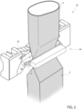
- each operative device 23, preferentially one of the respective first operative group 24 and the respective second operative group 25, comprises a pair of movable interaction tabs 26 configured to interact, in use, with tube 4 from opposite sides thereof.
- interaction tabs 26 of each pair of interaction tabs 26 are movable with respect to one another, preferentially so as to selectively move interaction tabs 26 towards and away from one another.
- each pair of interaction tabs 26 is controllable between a first limit position in which the respective interaction tabs 26 are configured to be, in use, detached from tube 4 and a second limit position in which the respective interaction tabs 26 are configured to be, in use, in contact with tube 4.
- the respective interaction tabs 26 of each pair of interaction tabs 26 may be closer to one another when being in the second limit position than when being in the first limit position. In other words, interaction tabs 26 are withdrawn from one another when being in the first limit position and are approached to one another when being in the second limit position.
- each pair of interaction tabs 26 may be configured to interact, preferentially when being in the second limit position, with the in use advancing tube 4 from opposite sides thereof for exerting a pulling force on tube 4.
- each pair of interaction tabs 26 may be configured to control and/or modify advancement of tube 4 such that tube 4 is "in register" with the respective operative device 23, meaning that each pair of interaction tabs 26 guarantees that the respective operative device 23, preferentially the respective first operative group 24 and the respective second operative group 25, transversally seal and/or cut tube 4 at an intended region of the respective pattern, in particular such that the respective finalized package 2 has the respective desired pattern.
- each pair of interaction tabs 26 may be configured to exert a controlled pulling force on tube 4 so as to "pull" tube 4 in a downstream direction along tube advancement path Q.
- the controlled pulling force may be dependent on the relative distance between the respective interaction tabs 26 of each pair, preferentially on the degree of controlling each pair of interaction tabs 26 between the respective first limit position and the respective second limit position.
- the controlled pulling force may depend on the actual interacting position in which the pair of interaction tabs 26 is stopped when interacting with tube 4, such actual interacting position being interposed between the respective first limit position and the respective second limit position or corresponding with the respective second limit position.
- the controlled pulling force is a function of the relative distance of the respective interaction tabs 26 from one another.
- the respective interaction tabs 26 are, in use, detached (distanced) from tube 4 advancing along tube advancement path Q, i.e. the respective interaction tabs 26 are not in contact with tube 4, and thus do not exert any pulling force on tube 4.
- the respective pair of interaction tabs 26 is in the respective first limit position the respective interaction tabs 26 are positioned so that they do not interact with tube 4 advancing along tube advancement path Q.
- the respective interaction tabs 26 are, in use, in contact with tube 4 advancing along tube advancement path Q, and preferentially exert a maximum pulling force on tube 4.
- each pair of interaction tabs 26 may be configured such to be controlled (i.e. stopped) between the first limit position and the second limit position so as to control the pulling force exerted by the respective interaction tabs 26 on tube 4.
- each pair of interaction tabs 26 may also be configured to fold tube 4 so as to define flaps of the respective semi-finalized packs.
- each semi-finalized packs may comprise a pair of sealing fins arranged at opposite ends of the semi-finalized pack and flaps laterally protruding from the opposite ends.
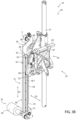
- package forming apparatus 10 may also comprise a cam mechanism 28 configured to control the relative position of each pair of interaction tabs 26 with respect to one another during advancement of each first operative group 24 and the respective second operative group 25 along respectively the respective first advancement path, preferentially the respective operative portion, and the respective second advancement path, preferentially the respective operative portion.
- cam mechanism 28 configured to control the relative position of each pair of interaction tabs 26 with respect to one another during advancement of each first operative group 24 and the respective second operative group 25 along respectively the respective first advancement path, preferentially the respective operative portion, and the respective second advancement path, preferentially the respective operative portion.
- cam mechanism 28 may be configured to selectively control the relative position of each pair of interaction tabs 26 with respect to one another for selectively controlling the respective pair of interaction tabs 26 between the respective first limit position and the respective second limit position.
- cam mechanism 28 may be configured to control each pair of interaction tabs 26 between any relative position between the respective first limit position and the respective second limit position.
- cam mechanism 28 may comprise:
- advancement direction D1 may be defined by and/or be relative to cam channel 29.
- each cam follower 30 with the respective cam channel 29 allows to control the relative position between the respective interaction tabs 26 of the respective pair of interaction tabs 26, preferentially so as to control the respective pair of interaction tabs 26 between the first limit position and the second limit position.
- each cam follower 30 with the respective cam channel 29 allows to control the relative position between the respective interaction tabs 26 of the respective pair so as to control the pulling force acting on tube 4, preferentially so as to guarantee that tube 4 is transversally sealed and/or cut at the desired position so as to be able to obtain packages 2 with the desired pattern.
- cam mechanism 28 may comprise one respective cam channel 29 and one respective cam follower 30 for each operative device 23.
- cam mechanism 28 may comprise two cam channels 29 and two cam followers 30.
- cam mechanism 28 may further comprise an actuation unit 31 configured to move, preferentially to selectively move, each cam channel 29 along a respective cam movement direction D2 transversal to the respective advancement direction D1.
- actuation unit 31 may be configured to change the respective position of each cam channel 29, whereby the respective advancement direction D1 is defined in relation to the respective cam channel 29.
- each cam channel 29 may be arranged in different positions by actuation unit 31.
- cam channel 29 always defines the respective advancement direction D1.
- each cam channel 29 along the respective cam movement direction D2 leads also to a movement of the respective cam follower 30 along the respective cam movement direction D2 resulting in a modification of the relative position of the respective interaction tabs 26 of the respective pair with respect to one another, preferentially so as to control the respective pair of interaction tabs 26 between the respective first limit position and the respective second limit position.
- actuation unit 31 may be configured to control the extent of movement of cam channel 29 along the respective cam movement direction D2 so as to obtain a control of the pulling force exerted on tube 4 by the respective pair of interaction tabs 26.
- each cam channel 29 rectilinearly extends along a central axis B.
- each cam follower 30 advances, in use, rectilinearly within the respective cam channel 29.
- each cam channel 29 may comprise a respective first wall 32 and a respective second wall 33 spaced apart from the respective first wall 32.
- the respective cam follower 29 may be interposed between and may be configured to engage, in use, the respective first wall 32 and the respective second wall 33, preferentially such that movement of cam channel 29 along the respective cam movement direction D2 is transferred to the respective cam follower 30.
- each first wall 32 and the respective second wall 33 may be parallel to one another.
- each first wall 32 and/or the respective second wall 33 may be parallel to the respective central axis B.
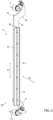
- actuation unit 31 may comprise one or more support bars 34, each one carrying one respective cam channel 29 and one or more actuators 35 (only partially shown), each one coupled to one respective support bar 34 and configured to move the support bar 34 along the respective cam movement direction D2 such to move the respective cam channel 29 along the cam movement direction D2.
- each support bar 34 may be movably connected to a respective support column (not shown) of package forming apparatus 10.
- each cam movement direction D2 may comprise a first component perpendicular to the respective central axis B and a second component parallel to the respective central axis B.
- movement of each cam channel 29 along the respective cam movement direction D2 may be a linear movement.
- each support bar 34 may be designed such that the respective cam movement direction D2 comprises the first component and the second component.
- each support bar 34 may be designed such that activation of the respective actuator 35 may result in movement along the respective cam movement direction D2.
- each support bar 34 may comprise a first end portion 40 and a second end portion 41 opposite to the respective first end portion 40.
- each first end portion 40 may be angularly movable about a first rotation axis C and the respective second end portion 41 may be angularly movable about a second rotation axis E so as to move the respective support bar 34 and thereby also the respective cam channel 29 along the respective cam movement direction D2.
- each first end portion 40 and each second end portion 41 may be connected to the respective support column so as to be angularly movable about the respective first rotation axis C and the respective second rotation axis E, respectively.
- each support bar 34 may also comprise a respective intermediate portion 42 interposed between and/or connected to the respective first end portion 40 and the respective second end portion 41.
- each cam channel 29 may be mounted onto the respective intermediate portion 42.
- each first end portion 40 and the respective second end portion 41 may transversally and/or laterally protrude away from the respective intermediate portion 42.
- each intermediate portion 42 may rectilinearly extend along a respective longitudinal axis F.
- each actuator 35 may be coupled to one of the respective first end portion 40 and the respective second end portion 41. Moreover, the other one of the respective first end portion 40 and the respective second end portion 41 angularly moves as a result of the angular movement actuated by the respective actuator 35.
- each actuator 35 may be connected to the respective second end portion 41 and may be configured to directly actuate the respective angular movement about the respective second rotation axis E, while the respective first end portion 40 angularly moves about the respective first rotation axis C due to the angular movement of the respective second end portion 41.
- each actuator 35 may comprise an electrical motor 36.
- each cam mechanism 28 may also comprise one or more coupling bars 43, each one carrying one respective cam follower 30 and being coupled to one respective pair of interaction tabs 26.
- each operative device 23 may comprise an actuation mechanism 49 (only partially shown) operatively coupled to the respective pair of interaction tabs 26 and configured to actuate the relative movement of the respective interaction tabs 26 with respect to one another.
- actuation mechanism 49 (only partially shown) operatively coupled to the respective pair of interaction tabs 26 and configured to actuate the relative movement of the respective interaction tabs 26 with respect to one another.
- each coupling bar 43 may be connected to the respective actuation mechanism 49 and being configured to transfer the movement of the respective cam follower 30 to the respective actuation mechanism 49, which in turn transfers the movement to the respective pair of interaction tabs 26.
- each coupling bar 43 may also be angularly movably connected to the respective operative device 23, preferentially one of the respective first operative group 24 and the respective second operative group 25. More preferentially, each coupling bar 43 may be angularly movable about a rotation axis G.
- angular movement of coupling bar 43 may result in a linear movement of an actuator bar of the respective actuation mechanism 49.
- each operative device 23 may comprise a connecting structure 44 having a respective first portion 45 and a respective second portion 46 being movable with respect to one another. Preferentially, each first portion 45 and the respective second portion 46 may be moved towards and may be withdrawn from one another.
- each first operative group 24 may be connected to and/or carried by the respective first portion 45 and the respective second operative group 25 may be connected to and/or carried by the respective second portion 46. Moreover, movement of each first portion 45 and of the respective second portion 46 leads to movement of the respective first operative group 24 and the respective second operative group 25, respectively.
- each coupling bar 43 may be angularly movably connected to and/or hinged to one of the respective first portion 45 and the respective second portion 46, preferentially thereby defining the respective rotation axis G.
- cam mechanism 28 is coordinated with respect to the respective relative positions of the respective first operative group 24 and the respective second operative group 25 and/or the respective first portion 45 and the respective second portion 46 with respect to one another.
- each pair of interaction tabs 26 must interact with tube 4 such that the transversal sealing and the transversal cutting occurs at the correct position. Accordingly, each pair of interaction tabs 26 must be controlled from the respective first limit position towards the respective second limit position, prior or during control of the respective operative device 23 from the rest configuration to the active configuration.
- first portion 45 and the respective second portion 46 are withdrawn from one another with the respective operative device 23 being in the respective rest configuration (i.e. the respective first operative group 24 and the respective second operative group 25 being withdrawn from one another), in which also the respective pair of interaction tabs 26 are in or close to the respective first limit position.
- first portion 45 and the respective second portion 46 are approached to one another resulting also in the respective first operative group 24 and the respective second operative group 25 being approached to one another.
- the condition shown in Figure 3B corresponds to the respective operative device 23 being in the respective active configuration.
- the respective interaction tabs 26 of the respective pair are moved towards one another so as to engage and interact with tube 4.
- each operative device 23 may comprise at least one sealing assembly having a respective sealing element 47 and a respective counter-sealing element 48 configured to transversally seal in cooperation with one another tube 4.
- each first operative group 24 may comprise the respective sealing element 47 and the respective second operative group 25 may comprise the respective counter-sealing element 48.
- each sealing element 47 and the respective counter-sealing element 48 may be configured to at least transversally compress, in particular flat-lay and squeeze, and to transversally seal tube 4, in particular during advancement of tube 4 along tube advancement path Q.
- each sealing element 47 and the respective counter-sealing element 48 may be configured to engage tube 4 from opposite sides thereof.
- each sealing element 47 may comprise a source configured to generate the energy needed to obtain the sealing effect.
- sealing element 58 may be a sonotrode having ultrasound-emitters or sealing element 58 may have an electromagnetic induction source.
- Each counter-sealing element 48 may be a passive element (i.e. not having an active source).
- counter-sealing element 48 may be a metal anvil or a deformable pad.
- each operative device 23 may comprise at least one cutting assembly configured to transversally cut tube 4.
- each cutting assembly may be configured to transversally cut tube 4 after sealing of tube 4 by means of the respective sealing assembly.
- each sealing element 47 and the respective counter-sealing element 48 may be moved towards and withdrawn from one another with the respective first operative group 24 and the respective second operative group 25 being moved towards and withdrawn from one another, respectively.
- Each cutting assembly may comprise a cutting blade being associated with one of the respective first operative group 24 and the respective second operative group 25, preferentially with the respective second operative group 25.
- each operative device 23 may also comprise a forming shell assembly (not shown and known as such) configured to form tube 4, preferentially to at least partially define the shape of packages 2.
- each forming shell assembly may at least comprise a first half-shell (not shown and known as such) and a second half-shell 59 configured to at least partially define in cooperation with one another the shape of packages 2.
- each first half-shell and the respective second half-shell 59 may be configured to contact tube 4 from opposite sides thereof.
- one of the first half-shell and second half-shell 59 may be coupled to first operative group 24 and the other one of the first half-shell and second half-shell 59 may be coupled to second operative group 25.
- one of the first half-shell and second half-shell 59 may be coupled to sealing element 47 and the other one of the first half-shell and second half-shell 59 may be coupled to counter-sealing element 48.
- each first half-shell and the respective second half-shell 49 may be moved towards and withdrawn from one another with the respective first operative group 24 and the respective second operative group 25 being moved towards and withdrawn from one another, respectively.
- package forming apparatus 10 may comprise a support structure 55 movably carrying each operative device 23.
- Support structure 55 may comprise one or more support assemblies 56 (only one shown), each one movably carrying one respective operative device 23.
- package forming apparatus 10 may comprise two, preferentially exactly two, operative devices 23, and support structure 55 may comprise two, preferentially exactly two, support assemblies 56.
- support assemblies 56 may be spaced apparat from one another.
- support assemblies 56 may be arranged such that, in use, the advancing tube 4 may be interposed between support assemblies 56.
- support assemblies 56 may define and/or delimit the advancement space through which, in use, tube 4 advances.
- each support assembly 56 may comprise a respective first guide 57 and a respective second guide 58 spaced apart from the respective first guide 29.
- each connecting structure 44 may be movably coupled to the respective first guide 57 and the respective second guide 58.
- each support bar 34 may extend parallel to and/or may be arranged adjacent to the respective second guide 58.
- each operative device 23 may be connected to the respective connecting structure 44 such to protrude into the advancement space of tube 4.
- each first operative group 24 and each second operative group 25 may be carried by the respective first portion 45 and the respective second portion 46, respectively, such to be arranged within the advancement space.
- packaging machine 1 produces packages 2 filled with the pourable product.
- conveying device 11 advances web 3 along web advancement path P.
- Tube forming and sealing device 12 forms tube 4 from the advancing web 3 and longitudinally seals tube 4.
- filling device 13 fills tube 4 with the pourable product and package forming apparatus 10 forms, transversally seals and transversally cuts tube 4 so as to obtain packages 2.
- operative devices 23 transversally seal, and preferentially cut tube 4. Preferentially, operative devices 23 also form packages 2 from tube 4.
- each operative device 23 the respective first operative group 24 and the respective second operative group 25 are cyclically moved towards and withdrawn from one another.
- each pair of interaction tabs 26 is selectively moved between the respective first limit position and the respective second limit position by means of cam mechanism 28.
- Each first operative group 24 and the respective second operative group 25 advance along respectively the respective first advancement path and the respective second advancement path, leading to the respective cam follower 30 moving within the respective cam channel 29 along the respective advancement direction D1.
- each actuation unit 31 moves the respective cam channel 29 along the respective cam movement direction D2 also resulting in movement of the respective cam follower 30 along the cam movement direction D2, which again results in a change of the relative position between the respective interaction tabs 26 of the respective pair.
- cam mechanism 28 comes along with a simple design allowing a precise control of the relative positions between the respective interaction tabs 26 of each pair of interaction tabs 26.
- cam mechanism 28 can be easily installed with a limited need of installation precision as each cam follower 30 interacts with cam channel 29, more precisely with the respective first wall 32 and the respective second wall 33.
Landscapes
- Engineering & Computer Science (AREA)
- Mechanical Engineering (AREA)
- Chemical & Material Sciences (AREA)
- Composite Materials (AREA)
- Containers And Plastic Fillers For Packaging (AREA)
- Package Closures (AREA)
- Lining Or Joining Of Plastics Or The Like (AREA)
Abstract
Description
- The present invention relates to a package forming apparatus for a packaging machine for forming packages filled with a pourable product, preferentially a pourable food product.
- Advantageously, the present invention also relates to a packaging machine for forming packages filled with a pourable product, preferentially a pourable food product.
- As is known, many liquid or pourable food products, such as fruit juice, UHT (ultra-high-temperature treated) milk, wine, tomato sauce, etc., are sold in packages made of sterilized packaging material.
- A typical example is the parallelepiped-shaped package for liquid or pourable food products known as Tetra Brik Aseptic (registered trademark), which is made by sealing and folding laminated strip packaging material. The packaging material has a multilayer structure comprising a base layer, e.g. of paper, covered on both sides with layers of heat-seal plastic material, e.g. polyethylene. In the case of aseptic packages for long-storage products, such as UHT milk, the packaging material also comprises a layer of oxygen-barrier material (an oxygen-barrier layer), e.g. an aluminum foil, which is superimposed on a layer of heat-seal plastic material, and is in turn covered with another layer of heat-seal plastic material forming the inner face of the package eventually contacting the food product.
- Packages of this sort are normally produced on fully automatic packaging machines, which advance a web of packaging material through a sterilization apparatus for sterilizing the web of packaging material at a sterilization station and to an isolation chamber (a closed and sterile environment) in which the sterilized web of packaging material is maintained and advanced. During advancement of the web of packaging material through the isolation chamber, the web of packaging material is folded and sealed longitudinally at a tube forming station to form a tube having a longitudinal seam portion, the tube being further fed along a vertical advancing direction.
- For completing the forming operations, the tube is filled with a pourable product, in particular a pourable food product, and is transversally sealed and subsequently cut along equally spaced transversal cross sections within a package forming apparatus of the packaging machine during advancement along the vertical advancing direction.
- Pillow packages are so obtained, each pillow package having a longitudinal sealing band, a top transversal sealing band and a bottom transversal sealing band.
- A typical packaging machine comprises a conveying device for advancing the web of packaging material along a web advancement path and the tube formed from the web of packaging material along a tube advancement path, the sterilization apparatus for sterilizing the web of packaging material prior to its formation into the tube, a tube forming and sealing device at least partially arranged within the isolation chamber and being configured to form the tube from the advancing web of packaging material and to longitudinally seal the tube, a filling device for filling the tube with the pourable product and the package forming apparatus adapted to form, transversally seal and cut individual packages from the tube of packaging material.
- The package forming apparatus comprises at least one operative device having at least a first operative group and a second operative group configured to at least partially form and to transversally seal and cut in cooperation the, in use, advancing tube.
- The operative device also comprises pair of interaction tabs controllable between a first limit position in which the interaction tabs are detached from the tube and a second limit position in which the interaction tabs interact with the advancing tube. The interaction tabs are more distanced from one another when being in the first limit position than when being in the second limit position.
- The package forming apparatus also comprises a cam mechanism configured to control the pair of interaction tabs between the first operative configuration and the second operative configuration.
- The cam mechanism comprises a parallelogram system on which a cam follower runs, coming along with the need of a precise mounting.
- Even though the known package forming apparatuses and/or packaging machines work satisfactorily well, a desire is felt in the sector to further improve the known package forming apparatuses and/or the known packaging machines.
- It is therefore an object of the present invention to provide an improved package forming apparatus.
- Additionally, it is an object of the present invention to provide an improved packaging machine.
- According to the present invention, there is provided a package forming apparatus as claimed in
claim 1. - Preferred non-limiting embodiments of the package forming apparatus are claimed in the claims being directly and indirectly dependent on
claim 1. - According to the present invention, there is also provided a packaging machine according to
claim 15. - A non-limiting embodiment of the present invention will be described by way of example with reference to the accompanying drawings, in which:
-
Figure 1 is a schematic view of a packaging machine having a package forming apparatus according to the present invention, with parts removed for clarity; -
Figure 2 is a schematic perspective view of a detail of the package forming apparatus ofFigure 1 , with parts removed for clarity; -
Figure 3A is a perspective view of a detail of the package forming apparatus ofFigure 1 being in a first configuration, with parts removed for clarity; -
Figure 3B is a perspective view of the detail of the package forming apparatus ofFigure 3A being in a second configuration, with parts removed for clarity; -
Figure 4 is an enlarged perspective view of a portion of the detail ofFigures 3A and3B , with parts removed for clarity; -
Figure 5 is a perspective view of another portion of the detail ofFigures 3A and3B , with parts removed for clarity; and -
Figure 6 is an enlarged perspective view of some details of the package forming apparatus ofFigures 1 and2 , with parts removed for clarity. -
Number 1 indicates as a whole a packaging machine for producing sealedpackages 2 of a pourable product, in particular a pourable food product, such as milk, milk drinks, yoghurt, yoghurt drinks, fruit juice, wine, tomato sauce, emulsions, beverages containing pulp, salt, sugar, etc. - In more detail,
packaging machine 1 may be configured to producepackages 2 from a multilayer packaging material. Preferentially, a multilayer packaging material having heat seal properties (i.e. portions of the multilayer packaging material can be sealed to one another). - In further detail, the multilayer packaging material may comprise at least one layer of fibrous material, such as e.g. paper or cardboard, and at least two layers of heat-seal plastic material, e.g. polyethylene, interposing the layer of fibrous material in between one another. Preferentially, one of these two layers of heat-seal plastic material may define the inner face of
packages 2 contacting the pourable product. - Moreover, the multilayer packaging material may also comprise a layer of gas- and light-barrier material, e.g. aluminum foil or ethylene vinyl alcohol (EVOH) film, preferentially being arranged between one of the layers of heat-seal plastic material and the layer of fibrous material.
- Preferentially, the packaging material may also comprise a further layer of heat-seal plastic material being interposed between the layer of gas- and light-barrier material and the layer of fibrous material.
- In further detail, the multilayer packaging material may be provided in the form of a
web 3. - Preferentially,
web 3 comprises successively arranged patterns, each pattern defining a final graphical pattern of therespective package 2. In other words,packaging machine 1 operates, in use, such to guarantee thatpackages 2 comprise the respective pattern. - Furthermore,
packaging machine 1 may be configured to producepackages 2 by forming atube 4 fromweb 3, longitudinally sealingtube 4,filling tube 4 with the pourable product and to transversally seal, and preferentially transversally cuttube 4. - According to some possible non-limiting embodiments, each
package 2 may extend along a longitudinal axis A. - According to some possible embodiments, each
package 2 may comprise at least a firsttransversal sealing band 5 arranged at a first end ofpackage 2, and preferentially also a second transversal sealing band arranged at a second end ofpackage 2 opposite to the first end. - Preferentially, each first
transversal sealing band 5 may be substantially spaced apart from the respective second transversal sealing band along the respective longitudinal axis A. - Preferentially, each first
transversal sealing band 5 may define a transversal top sealing band and each second transversal sealing band may define a transversal bottom sealing band. - Moreover, each
package 2 may also comprise alongitudinal seam portion 6. Preferentially, each firsttransversal sealing band 5 and/or each second transversal sealing band may be transversal, preferentially perpendicular, to the respectivelongitudinal seam portion 6. - With particular reference to
Figure 1 ,packaging machine 1 may comprise apackage forming apparatus 10 configured to transversally seal, and preferentially to transversally cuttube 4 for obtaining semi-finalized packs, preferentially package pouches. Preferentially,package forming apparatus 10 may also be configured to formtube 4. - Preferentially,
package forming apparatus 10 may comprise an advancement space within which, in use,tube 4 advances. - Additionally
packaging machine 1 may comprise a final folding apparatus configured to receive the semi-finalized packs frompackage forming apparatus 10 and to formpackages 2 from the semi-finalized packs. - Moreover,
packaging machine 1 may also comprise: - a
conveying device 11 configured to advanceweb 3 along a web advancement path P, preferentially to a tube forming station, at which, in use,web 3 is formed intotube 4, and configured to advancetube 4 along a tube advancement path Q; - a tube forming and
sealing device 12 configured to formtube 4 from the, in use, advancingweb 3 and to longitudinallyseal tube 4; and - a filling device 13 for
filling tube 4 with the pourable product. - In further detail,
packaging machine 1 may also comprise anisolation chamber 14, preferentially delimiting aninner environment 15 from anouter environment 16. Preferentially,inner environment 15 may be a sterile environment, preferably containing a controlled atmosphere. - Preferentially, tube forming and
sealing device 12 may be at least partially arranged withinisolation chamber 14, in particularinner environment 15, and being configured to fold and longitudinallyseal tube 4 withinisolation chamber 14, in particularinner environment 15. - Moreover,
packaging machine 1 may also comprise a sterilization unit configured to sterilize the, in use, advancingweb 3, preferentially the sterilization unit being arranged upstream of tube forming and sealingdevice 12 along web advancement path P. - In more detail,
conveying device 11 may be configured to advancetube 4 and any intermediates oftube 4 along tube advancement path Q, preferentially from tube forming andsealing device 12 to and/or at least partially withinpackage forming apparatus 10. Preferentially, with the wording intermediates oftube 4 any configuration ofweb 3 is meant prior to obtaining the tube structure and after folding ofweb 3 by tube forming and sealingdevice 12 has started. In other words, the intermediates oftube 4 are a result of the gradual folding ofweb 3 so as to obtaintube 4, preferentially by overlapping the (longitudinal) edges ofweb 3 with one another. - According to some possible non-limiting embodiments, tube forming and sealing
device 12 may be arranged such thattube 4 may have a vertical orientation. - More specifically, tube forming and sealing
device 12 may comprise at least two formingring assemblies 17, preferentially arranged withinisolation chamber 14, even more preferentially arranged withininner environment 15, being configured to gradually fold in cooperation with one anotherweb 3 intotube 4, preferentially by overlapping the edges ofweb 3 with one another. Thereby, in use,seam portion 6 oftube 4 may be formed. - Additionally, tube forming and sealing
device 12 may comprise a sealinghead 18, preferentially arranged withinisolation chamber 14, even more preferentially withininner environment 15, and configured to longitudinallyseal tube 4, preferentially alonglongitudinal seam portion 6. - Moreover, tube forming and sealing
device 12 may also comprise a pressure assembly configured to exert a mechanical force onlongitudinal seam portion 6 to ensure sealing oftube 4 alonglongitudinal seam portion 6. - Preferentially, filling device 13 may comprise a filling
pipe 19 being configured to direct, in use, the pourable product intotube 4. Preferentially, fillingpipe 19 may, in use, be at least partially placed withintube 4 for feeding, in use, the pourable product intotube 4. - With particular reference to
Figures 1 and2 ,package forming apparatus 10 may comprise one or more, preferentially a plurality of, operative devices 23 (only partially shown to the extent necessary for the comprehension of the present invention), each one configured to at least transversally seal and preferentially to transversally cuttube 4 and/or to form (shape)tube 4. - Preferentially,
package forming apparatus 10 may be configured to control eachoperative device 23 such to transversally seal and preferentially transversally cuttube 4 along equally spaced transversal cross sections, preferentially thereby forming the respective firsttransversal sealing bands 5 and/or the respective second transversal sealing bands. - According to some possible non-limiting embodiments,
package forming apparatus 10 may comprise at least twooperative devices 23, preferentially exactly two. - In further detail and with particular reference to
Figure 2 , eachoperative device 23 may comprise at least a firstoperative group 24 and a secondoperative group 25 configured to cooperate with one another to at least transversally seal, and preferentially cut and to also at least partially form,tube 4. - In particular, each
first operative group 24 and the respective secondoperative group 25 may be movable with respect to one another, preferentially so as to move eachfirst operative group 24 and the respective secondoperative group 25 towards and away from one another. - In more detail, each
operative device 23 may be controllable between an active configuration, in which the respective firstoperative group 24 and the respective secondoperative group 25 are moved towards one another to seal, and preferentially also to transversally cut and/or to at least partially form,tube 4 and a rest configuration, in which the respective firstoperative group 24 and the respective secondoperative group 25 are withdrawn from one another. - Moreover,
package forming apparatus 10 may also comprise a conveying unit configured to advance eachfirst operative group 24 and eachsecond operative group 25 along a respective first advancement path and a respective second advancement path, respectively. - In more detail, the first advancement path and the second advancement path may comprise an operative portion along which each
first operative group 24 and eachsecond operative group 25 advance, in use, in a direction of advancement oftube 4 and a return portion along which eachfirst operative group 24 and eachsecond operative group 25 advance, in use, in a direction opposite to the direction of advancement oftube 4 so as to bring eachfirst operative group 24 and eachsecond operative group 25 back to the respective operative portion. - Moreover, each
operative device 23 may be controlled from the respective rest configuration to the respective active configuration during advancement of the respective firstoperative group 24 and the respective secondoperative group 25 along the respective operative portion, preferentially to transversally seal, and preferentially to also transversally cut and to at least partially form,tube 4. - In even further detail, in use, after completion of each transversal sealing, and preferentially the respective transversal cutting and/or the partial forming, of
tube 4, eachoperative device 23 may be controlled back to the respective rest configuration. - In other words, during advancement of each
first operative group 24 and the respective secondoperative group 25 along the respective operative portions, eachfirst operative group 24 and the respective secondoperative group 25 may be moved towards one another. After termination of the respective transversal sealing, and preferentially the respective transversal cutting and/or the partial forming, oftube 4, eachfirst operative group 24 and the respective secondoperative group 25 are withdrawn from one another. - With particular reference to
Figure 6 , eachoperative device 23, preferentially one of the respective firstoperative group 24 and the respective secondoperative group 25, comprises a pair ofmovable interaction tabs 26 configured to interact, in use, withtube 4 from opposite sides thereof. - In particular,
interaction tabs 26 of each pair ofinteraction tabs 26 are movable with respect to one another, preferentially so as to selectively moveinteraction tabs 26 towards and away from one another. - Preferentially, each pair of
interaction tabs 26 is controllable between a first limit position in which therespective interaction tabs 26 are configured to be, in use, detached fromtube 4 and a second limit position in which therespective interaction tabs 26 are configured to be, in use, in contact withtube 4. - Preferentially, the
respective interaction tabs 26 of each pair ofinteraction tabs 26 may be closer to one another when being in the second limit position than when being in the first limit position. In other words,interaction tabs 26 are withdrawn from one another when being in the first limit position and are approached to one another when being in the second limit position. - In more detail, each pair of
interaction tabs 26 may be configured to interact, preferentially when being in the second limit position, with the inuse advancing tube 4 from opposite sides thereof for exerting a pulling force ontube 4. - In even more detail, each pair of
interaction tabs 26 may be configured to control and/or modify advancement oftube 4 such thattube 4 is "in register" with the respectiveoperative device 23, meaning that each pair ofinteraction tabs 26 guarantees that the respectiveoperative device 23, preferentially the respective firstoperative group 24 and the respective secondoperative group 25, transversally seal and/or cuttube 4 at an intended region of the respective pattern, in particular such that the respective finalizedpackage 2 has the respective desired pattern. - Furthermore, each pair of
interaction tabs 26 may be configured to exert a controlled pulling force ontube 4 so as to "pull"tube 4 in a downstream direction along tube advancement path Q. - In further detail, the controlled pulling force may be dependent on the relative distance between the
respective interaction tabs 26 of each pair, preferentially on the degree of controlling each pair ofinteraction tabs 26 between the respective first limit position and the respective second limit position. In other words, the controlled pulling force may depend on the actual interacting position in which the pair ofinteraction tabs 26 is stopped when interacting withtube 4, such actual interacting position being interposed between the respective first limit position and the respective second limit position or corresponding with the respective second limit position. In even other words, the controlled pulling force is a function of the relative distance of therespective interaction tabs 26 from one another. - Preferentially, with the respective pair of
interaction tabs 26 being in the respective first limit position therespective interaction tabs 26 are, in use, detached (distanced) fromtube 4 advancing along tube advancement path Q, i.e. therespective interaction tabs 26 are not in contact withtube 4, and thus do not exert any pulling force ontube 4. In other words, when the respective pair ofinteraction tabs 26 is in the respective first limit position therespective interaction tabs 26 are positioned so that they do not interact withtube 4 advancing along tube advancement path Q. - Preferentially, with the respective pair of
interaction tabs 26 being in the respective second limit position therespective interaction tabs 26 are, in use, in contact withtube 4 advancing along tube advancement path Q, and preferentially exert a maximum pulling force ontube 4. - Furthermore, each pair of
interaction tabs 26 may be configured such to be controlled (i.e. stopped) between the first limit position and the second limit position so as to control the pulling force exerted by therespective interaction tabs 26 ontube 4. - Alternatively or additionally, each pair of
interaction tabs 26 may also be configured to foldtube 4 so as to define flaps of the respective semi-finalized packs. - In this context, it should be considered that each semi-finalized packs may comprise a pair of sealing fins arranged at opposite ends of the semi-finalized pack and flaps laterally protruding from the opposite ends.
- According to some preferred non-limiting embodiments and with particular reference to
Figures 3A to 5 ,package forming apparatus 10 may also comprise acam mechanism 28 configured to control the relative position of each pair ofinteraction tabs 26 with respect to one another during advancement of eachfirst operative group 24 and the respective secondoperative group 25 along respectively the respective first advancement path, preferentially the respective operative portion, and the respective second advancement path, preferentially the respective operative portion. - More specifically,
cam mechanism 28 may be configured to selectively control the relative position of each pair ofinteraction tabs 26 with respect to one another for selectively controlling the respective pair ofinteraction tabs 26 between the respective first limit position and the respective second limit position. Preferentially,cam mechanism 28 may be configured to control each pair ofinteraction tabs 26 between any relative position between the respective first limit position and the respective second limit position. - With particular reference to
Figures 3A to 5 ,cam mechanism 28 may comprise: - one or
more cam channels 29; and - one or
more cam followers 30, each one connected to one respective pair ofinteraction tabs 26, movably arranged within onerespective cam channel 29, and being configured to move within therespective cam channel 29 along an advancement direction D1 and during and/or as a consequence of the advancement of the respective firstoperative group 24 and the respective secondoperative group 25 along respectively the first advancement path, preferentially the respective operative portion, and the second advancement path, preferentially the respective operative portion. - In particular, advancement direction D1 may be defined by and/or be relative to
cam channel 29. - Advantageously, the interaction of each
cam follower 30 with therespective cam channel 29 allows to control the relative position between therespective interaction tabs 26 of the respective pair ofinteraction tabs 26, preferentially so as to control the respective pair ofinteraction tabs 26 between the first limit position and the second limit position. - In more detail, the interaction of each
cam follower 30 with therespective cam channel 29 allows to control the relative position between therespective interaction tabs 26 of the respective pair so as to control the pulling force acting ontube 4, preferentially so as to guarantee thattube 4 is transversally sealed and/or cut at the desired position so as to be able to obtainpackages 2 with the desired pattern. - According to some preferred non-limiting embodiments,
cam mechanism 28 may comprise onerespective cam channel 29 and onerespective cam follower 30 for eachoperative device 23. In the specific example embodiment disclosed,cam mechanism 28 may comprise twocam channels 29 and twocam followers 30. - Advantageously,
cam mechanism 28 may further comprise anactuation unit 31 configured to move, preferentially to selectively move, eachcam channel 29 along a respective cam movement direction D2 transversal to the respective advancement direction D1. - It should be noted that
actuation unit 31 may be configured to change the respective position of eachcam channel 29, whereby the respective advancement direction D1 is defined in relation to therespective cam channel 29. In other words, eachcam channel 29 may be arranged in different positions byactuation unit 31. However,cam channel 29 always defines the respective advancement direction D1. - Moreover, movement of each
cam channel 29 along the respective cam movement direction D2 leads also to a movement of therespective cam follower 30 along the respective cam movement direction D2 resulting in a modification of the relative position of therespective interaction tabs 26 of the respective pair with respect to one another, preferentially so as to control the respective pair ofinteraction tabs 26 between the respective first limit position and the respective second limit position. - Preferentially,
actuation unit 31 may be configured to control the extent of movement ofcam channel 29 along the respective cam movement direction D2 so as to obtain a control of the pulling force exerted ontube 4 by the respective pair ofinteraction tabs 26. - According to some preferred non-limiting embodiments, each
cam channel 29 rectilinearly extends along a central axis B. - Moreover, each
cam follower 30 advances, in use, rectilinearly within therespective cam channel 29. - In further detail, each
cam channel 29 may comprise a respectivefirst wall 32 and a respectivesecond wall 33 spaced apart from the respectivefirst wall 32. Therespective cam follower 29 may be interposed between and may be configured to engage, in use, the respectivefirst wall 32 and the respectivesecond wall 33, preferentially such that movement ofcam channel 29 along the respective cam movement direction D2 is transferred to therespective cam follower 30. - In more detail, each
first wall 32 and the respectivesecond wall 33 may be parallel to one another. - Advantageously, each
first wall 32 and/or the respectivesecond wall 33 may be parallel to the respective central axis B. - In further detail and with particular reference to
Figures 3A ,3B and5 ,actuation unit 31 may comprise one or more support bars 34, each one carrying onerespective cam channel 29 and one or more actuators 35 (only partially shown), each one coupled to onerespective support bar 34 and configured to move thesupport bar 34 along the respective cam movement direction D2 such to move therespective cam channel 29 along the cam movement direction D2. - Preferentially, each
support bar 34 may be movably connected to a respective support column (not shown) ofpackage forming apparatus 10. - According to some preferred non-limiting embodiments, each cam movement direction D2 may comprise a first component perpendicular to the respective central axis B and a second component parallel to the respective central axis B.
- In particular, movement of each
cam channel 29 along the respective cam movement direction D2 may be a linear movement. - With particular reference to
Figures 3A ,3B and5 , eachsupport bar 34 may be designed such that the respective cam movement direction D2 comprises the first component and the second component. In more detail, eachsupport bar 34 may be designed such that activation of therespective actuator 35 may result in movement along the respective cam movement direction D2. - More specifically, each
support bar 34 may comprise afirst end portion 40 and asecond end portion 41 opposite to the respectivefirst end portion 40. - Advantageously, each
first end portion 40 may be angularly movable about a first rotation axis C and the respectivesecond end portion 41 may be angularly movable about a second rotation axis E so as to move therespective support bar 34 and thereby also therespective cam channel 29 along the respective cam movement direction D2. - Preferentially, each
first end portion 40 and eachsecond end portion 41 may be connected to the respective support column so as to be angularly movable about the respective first rotation axis C and the respective second rotation axis E, respectively. - Moreover, each
support bar 34 may also comprise a respectiveintermediate portion 42 interposed between and/or connected to the respectivefirst end portion 40 and the respectivesecond end portion 41. - Preferentially, each
cam channel 29 may be mounted onto the respectiveintermediate portion 42. - According to some possible non-limiting embodiments, each
first end portion 40 and the respectivesecond end portion 41 may transversally and/or laterally protrude away from the respectiveintermediate portion 42. - According to some preferred non-limiting embodiments, each
intermediate portion 42 may rectilinearly extend along a respective longitudinal axis F. - According to some preferred non-limiting embodiments, each actuator 35 may be coupled to one of the respective
first end portion 40 and the respectivesecond end portion 41. Moreover, the other one of the respectivefirst end portion 40 and the respectivesecond end portion 41 angularly moves as a result of the angular movement actuated by therespective actuator 35. - In the specific case shown, each actuator 35 may be connected to the respective
second end portion 41 and may be configured to directly actuate the respective angular movement about the respective second rotation axis E, while the respectivefirst end portion 40 angularly moves about the respective first rotation axis C due to the angular movement of the respectivesecond end portion 41. - Preferentially, each actuator 35 may comprise an
electrical motor 36. - With particular reference to
Figures 3A to 4 , eachcam mechanism 28 may also comprise one or more coupling bars 43, each one carrying onerespective cam follower 30 and being coupled to one respective pair ofinteraction tabs 26. - Preferentially, each
operative device 23 may comprise an actuation mechanism 49 (only partially shown) operatively coupled to the respective pair ofinteraction tabs 26 and configured to actuate the relative movement of therespective interaction tabs 26 with respect to one another. - According to some preferred non-limiting embodiments, each
coupling bar 43 may be connected to therespective actuation mechanism 49 and being configured to transfer the movement of therespective cam follower 30 to therespective actuation mechanism 49, which in turn transfers the movement to the respective pair ofinteraction tabs 26. - According to some possible embodiments, each
coupling bar 43 may also be angularly movably connected to the respectiveoperative device 23, preferentially one of the respective firstoperative group 24 and the respective secondoperative group 25. More preferentially, eachcoupling bar 43 may be angularly movable about a rotation axis G. - Additionally, angular movement of
coupling bar 43 may result in a linear movement of an actuator bar of therespective actuation mechanism 49. - According to some preferred non-limiting embodiments, each
operative device 23 may comprise a connectingstructure 44 having a respectivefirst portion 45 and a respectivesecond portion 46 being movable with respect to one another. Preferentially, eachfirst portion 45 and the respectivesecond portion 46 may be moved towards and may be withdrawn from one another. - Preferentially, each
first operative group 24 may be connected to and/or carried by the respectivefirst portion 45 and the respective secondoperative group 25 may be connected to and/or carried by the respectivesecond portion 46. Moreover, movement of eachfirst portion 45 and of the respectivesecond portion 46 leads to movement of the respective firstoperative group 24 and the respective secondoperative group 25, respectively. - Preferentially, each
coupling bar 43 may be angularly movably connected to and/or hinged to one of the respectivefirst portion 45 and the respectivesecond portion 46, preferentially thereby defining the respective rotation axis G. - Preferentially and as shown in
Figures 3A and3B , operation ofcam mechanism 28 is coordinated with respect to the respective relative positions of the respective firstoperative group 24 and the respective secondoperative group 25 and/or the respectivefirst portion 45 and the respectivesecond portion 46 with respect to one another. - In other words, as already described above, each pair of
interaction tabs 26 must interact withtube 4 such that the transversal sealing and the transversal cutting occurs at the correct position. Accordingly, each pair ofinteraction tabs 26 must be controlled from the respective first limit position towards the respective second limit position, prior or during control of the respectiveoperative device 23 from the rest configuration to the active configuration. - In
Figure 3A ,first portion 45 and the respectivesecond portion 46 are withdrawn from one another with the respectiveoperative device 23 being in the respective rest configuration (i.e. the respective firstoperative group 24 and the respective secondoperative group 25 being withdrawn from one another), in which also the respective pair ofinteraction tabs 26 are in or close to the respective first limit position. - In
Figure 3B ,first portion 45 and the respectivesecond portion 46 are approached to one another resulting also in the respective firstoperative group 24 and the respective secondoperative group 25 being approached to one another. In particular, the condition shown inFigure 3B corresponds to the respectiveoperative device 23 being in the respective active configuration. Additionally, prior to firstoperative group 25 and the respective secondoperative group 26 being moved towards one another, therespective interaction tabs 26 of the respective pair are moved towards one another so as to engage and interact withtube 4. - With particular reference to
Figure 2 , eachoperative device 23 may comprise at least one sealing assembly having arespective sealing element 47 and a respectivecounter-sealing element 48 configured to transversally seal in cooperation with one anothertube 4. - According to some preferred non-limiting embodiments, each
first operative group 24 may comprise therespective sealing element 47 and the respective secondoperative group 25 may comprise the respectivecounter-sealing element 48. - More specifically, each sealing
element 47 and the respectivecounter-sealing element 48 may be configured to at least transversally compress, in particular flat-lay and squeeze, and to transversallyseal tube 4, in particular during advancement oftube 4 along tube advancement path Q. - Moreover, each sealing
element 47 and the respectivecounter-sealing element 48 may be configured to engagetube 4 from opposite sides thereof. - In further detail, each sealing
element 47 may comprise a source configured to generate the energy needed to obtain the sealing effect. For example, sealingelement 58 may be a sonotrode having ultrasound-emitters or sealingelement 58 may have an electromagnetic induction source. Eachcounter-sealing element 48 may be a passive element (i.e. not having an active source). For examplecounter-sealing element 48 may be a metal anvil or a deformable pad. - Additionally, each
operative device 23 may comprise at least one cutting assembly configured to transversally cuttube 4. Preferentially, each cutting assembly may be configured to transversally cuttube 4 after sealing oftube 4 by means of the respective sealing assembly. - Preferentially, each sealing
element 47 and the respectivecounter-sealing element 48 may be moved towards and withdrawn from one another with the respective firstoperative group 24 and the respective secondoperative group 25 being moved towards and withdrawn from one another, respectively. - Each cutting assembly may comprise a cutting blade being associated with one of the respective first
operative group 24 and the respective secondoperative group 25, preferentially with the respective secondoperative group 25. - According to some preferred non-limiting embodiments, each
operative device 23 may also comprise a forming shell assembly (not shown and known as such) configured to formtube 4, preferentially to at least partially define the shape ofpackages 2. - According to some preferred non-limiting embodiments, each forming shell assembly may at least comprise a first half-shell (not shown and known as such) and a second half-
shell 59 configured to at least partially define in cooperation with one another the shape ofpackages 2. Preferentially, each first half-shell and the respective second half-shell 59 may be configured to contacttube 4 from opposite sides thereof. - According to some preferred non-limiting embodiments one of the first half-shell and second half-
shell 59 may be coupled to firstoperative group 24 and the other one of the first half-shell and second half-shell 59 may be coupled to secondoperative group 25. - According to some preferred non-limiting embodiments one of the first half-shell and second half-
shell 59 may be coupled to sealingelement 47 and the other one of the first half-shell and second half-shell 59 may be coupled tocounter-sealing element 48. - Preferentially, each first half-shell and the respective second half-
shell 49 may be moved towards and withdrawn from one another with the respective firstoperative group 24 and the respective secondoperative group 25 being moved towards and withdrawn from one another, respectively. - With particular reference to
Figures 3A and3B ,package forming apparatus 10 may comprise asupport structure 55 movably carrying eachoperative device 23. -
Support structure 55 may comprise one or more support assemblies 56 (only one shown), each one movably carrying one respectiveoperative device 23. - According to some non-limiting embodiments,
package forming apparatus 10 may comprise two, preferentially exactly two,operative devices 23, andsupport structure 55 may comprise two, preferentially exactly two,support assemblies 56. - Preferentially,
support assemblies 56 may be spaced apparat from one another. - Even more preferentially,
support assemblies 56 may be arranged such that, in use, the advancingtube 4 may be interposed betweensupport assemblies 56. In other words,support assemblies 56 may define and/or delimit the advancement space through which, in use,tube 4 advances. - Advantageously, each
support assembly 56 may comprise a respectivefirst guide 57 and a respectivesecond guide 58 spaced apart from the respectivefirst guide 29. - Preferentially, each connecting
structure 44 may be movably coupled to the respectivefirst guide 57 and the respectivesecond guide 58. - According to some preferred non-limiting embodiments, each
support bar 34 may extend parallel to and/or may be arranged adjacent to the respectivesecond guide 58. - According to some preferred non-limiting embodiments, each
operative device 23 may be connected to the respective connectingstructure 44 such to protrude into the advancement space oftube 4. - In more detail, each
first operative group 24 and eachsecond operative group 25 may be carried by the respectivefirst portion 45 and the respectivesecond portion 46, respectively, such to be arranged within the advancement space. - In use,
packaging machine 1 producespackages 2 filled with the pourable product. - In more detail, conveying
device 11 advancesweb 3 along web advancement path P. Tube forming and sealingdevice 12forms tube 4 from the advancingweb 3 and longitudinally sealstube 4. Additionally, filling device 13 fillstube 4 with the pourable product andpackage forming apparatus 10 forms, transversally seals andtransversally cuts tube 4 so as to obtainpackages 2. - In further detail, during operation of
package forming apparatus 10,operative devices 23 transversally seal, and preferentially cuttube 4. Preferentially,operative devices 23 also formpackages 2 fromtube 4. - During operation of each
operative device 23, the respective firstoperative group 24 and the respective secondoperative group 25 are cyclically moved towards and withdrawn from one another. - Additionally, each pair of
interaction tabs 26 is selectively moved between the respective first limit position and the respective second limit position by means ofcam mechanism 28. - Each first
operative group 24 and the respective secondoperative group 25 advance along respectively the respective first advancement path and the respective second advancement path, leading to therespective cam follower 30 moving within therespective cam channel 29 along the respective advancement direction D1. - Moreover, each
actuation unit 31 moves therespective cam channel 29 along the respective cam movement direction D2 also resulting in movement of therespective cam follower 30 along the cam movement direction D2, which again results in a change of the relative position between therespective interaction tabs 26 of the respective pair. - The advantages of
package forming apparatus 10 and/orpackaging machine 1 according to the present invention will be clear from the foregoing description. - In particular,
cam mechanism 28 comes along with a simple design allowing a precise control of the relative positions between therespective interaction tabs 26 of each pair ofinteraction tabs 26. - An even other advantage can be seen in that the
cam mechanism 28 can be easily installed with a limited need of installation precision as eachcam follower 30 interacts withcam channel 29, more precisely with the respectivefirst wall 32 and the respectivesecond wall 33. - Clearly, changes may be made to package forming
apparatus 10 and/orpackaging machine 1 as described herein without, however, departing from the scope of protection as defined in the accompanying claims.
Claims (15)
- Package forming apparatus (10) for a packaging machine (1), the package forming apparatus (10) being configured to at least transversally seal a tube (4) made from a web of packaging material (3) for obtaining packages (2) from the tube (4);wherein the package forming apparatus (10) comprises at least one operative device (23) having a first operative group (24) and a second operative group (25) configured to at least transversally seal the tube (4);wherein one of the respective first operative group (24) and the respective second operative group (25) comprises a pair of movable interaction tabs (26) and the pair of interaction tabs (26) being configured to interact, in use, with the tube (4) from opposite sides thereof and being configured to move with respect to one another;wherein the package forming apparatus (10) comprises a cam mechanism (28) configured to control the relative position of the interaction tabs (26) of the pair of interaction tabs (26);wherein the cam mechanism (28) comprises at least:- a cam channel (29); and- a cam follower (30) coupled to the pair of interaction tabs (26), movably arranged within the cam channel (29), and being configured to move within the cam channel (28) along an advancement direction (D1);wherein the interaction of the cam follower (30) with the cam channel (29) allows to control the relative position of the interaction tabs (26) with respect to one another.
- Package forming apparatus according to claim 1, wherein the cam mechanism (28) further comprises an actuation unit (31) configured to move the cam channel (29) along a cam movement direction (D2) transversal to the advancement direction (D1);
wherein movement of the cam channel (28) along the cam movement direction (D2) leads also to a movement of the cam follower (29) along the cam movement direction (D2) resulting in a change of the relative position of the interaction tabs (26) with respect to one another. - Package forming apparatus according to claim 2, wherein the actuation unit (31) comprises a support bar (34) carrying the cam channel (29) and an actuator (35) coupled to the support bar (34) and configured to move the support bar (34) along the cam movement direction (D2) to move the cam channel (29) along the cam movement direction (D2).
- Package forming apparatus according to claim 3, wherein the cam channel (28) rectilinearly extends along a central axis (B);
wherein the support bar (34) is designed such that the cam movement direction (D2) comprises a first component perpendicular to the central axis (B) and a second component parallel to the central axis (B). - Package forming apparatus according to claim 3 or 4, wherein the support bar (34) comprises a first end portion (40) and a second end portion (41) opposite to the first end portion (40);
wherein the first end portion (40) is angularly movable about a first rotation axis (C) and the second end portion (41) is angularly movable about a second rotation axis (E) so as to move the support bar (34) and the cam channel (29) along the cam movement direction (D2). - Package forming apparatus according to claim 5, wherein the actuator (35) is coupled to one of the first end portion (40) and the second end portion (41).
- Package forming apparatus according to any one of claims 3 to 6, wherein the support bar (34) comprises a first end portion (40), a second end portion (41) opposite to the first end portion (40) and an intermediate portion (42) rectilinearly extending along a longitudinal axis (F);
wherein the first end portion (40) and the second end portion (41) transversally protrude from the intermediate portion (42). - Package forming apparatus according to any one of the preceding claims, wherein the pair of interaction tabs (26) is controllable between a first limit position in which the respective interaction tabs (26) are configured to be, in use, detached from the tube (4) and a second limit position in which the respective interaction tabs (26) are configured to be, in use, in contact with the tube (4);
wherein the interaction of the cam follower (30) with the cam channel (29) allows to control the pair of interaction tabs (26) between the respective first limit position and the respective second limit position. - Package forming apparatus according to any one of the preceding claims, wherein the cam channel (29) extends linearly.
- Package forming apparatus according to any one of the preceding claims, wherein the cam channel (28) comprises a first wall (32) and a second wall (33) spaced apart from the first wall (31);
wherein the cam follower (30) is interposed between the first wall (31) and the second wall (33) and is configured to engage the first wall (31) and the second wall (33). - Package forming apparatus according to any one of the preceding claims, wherein the cam mechanism (28) comprises a coupling bar (43) carrying the cam follower (30) and coupling the cam follower (30) to the pair of interaction tabs (26).
- Package forming apparatus according to claim 11, wherein the operative device (23) comprises an actuation mechanism (49) coupled to the pair of interaction tabs (26) and the coupling bar (43) and being configured to move the interaction tabs (26) of the pair of interaction tabs (26) as a result of the interaction of the cam follower (30) with the cam channel (29).
- Package forming apparatus according to any one of the preceding claims, and further comprising a conveying unit configured to advance the first operative group (24) and the second operative group (25) along a first advancement path and a second advancement path, respectively;
wherein the cam follower (30) is configured to move within the cam channel (29) along the advancement direction (D1) and during and/or as a consequence of the advancement of the first operative group (24) and the second operative group (25) moving along respectively the first advancement path and the second advancement path. - Package forming apparatus according to any one of the preceding claims, wherein one of the first operative group (24) and the second operative group (25) comprises a sealing element (47) and the other one of the first operative group (24) and the second operative group (25) comprises a counter-sealing element (48);
wherein the sealing element (47) and the counter-sealing element (48) are configured to compress and to transversally seal in cooperation the tube (4). - Packaging machine (1) for forming packages (2) of a pourable product from an advancing tube (4) formed and longitudinally sealed from a web of packaging material (3);
the packaging machine (1) comprises:- a conveying device (11) configured to advance the web of packaging material (3) along a web advancement path (P) and for advancing the tube (4) along a tube advancement path (Q) ;- a tube forming and sealing device (12) configured to form the tube (4) from the web of packaging material (3) and to longitudinally seal the tube (4);- a filling device (13) for filling the tube (4) with the pourable product; and- a package forming apparatus (10) according to any one of the preceding claims.
Applications Claiming Priority (1)
| Application Number | Priority Date | Filing Date | Title |
|---|---|---|---|
| IT102023000001572A IT202300001572A1 (en) | 2023-02-01 | 2023-02-01 | APPARATUS FOR FORMING PACKAGES FOR A PACKAGING MACHINE AND PACKAGING MACHINE FOR FORMING PACKAGES FILLED WITH A POURABLE PRODUCT |
Publications (2)
| Publication Number | Publication Date |
|---|---|
| EP4410522A1 true EP4410522A1 (en) | 2024-08-07 |
| EP4410522B1 EP4410522B1 (en) | 2026-05-13 |
Family
ID=85792181
Family Applications (1)
| Application Number | Title | Priority Date | Filing Date |
|---|---|---|---|
| EP24153891.7A Active EP4410522B1 (en) | 2023-02-01 | 2024-01-25 | Package forming apparatus for a packaging machine and packaging machine for forming packages filled with a pourable product |
Country Status (5)
| Country | Link |
|---|---|
| EP (1) | EP4410522B1 (en) |
| JP (1) | JP2026503302A (en) |
| CN (1) | CN120603702A (en) |
| IT (1) | IT202300001572A1 (en) |
| WO (1) | WO2024160636A1 (en) |
Citations (3)
| Publication number | Priority date | Publication date | Assignee | Title |
|---|---|---|---|---|
| US3008278A (en) * | 1959-09-11 | 1961-11-14 | James B Mccalley | Method and apparatus for forming, filling and sealing bags |
| IT201900007272A1 (en) * | 2019-05-27 | 2020-11-27 | Gd Spa | Container forming machine for pourable products |
| EP3760548A1 (en) * | 2019-07-01 | 2021-01-06 | Tetra Laval Holdings & Finance S.A. | A packaging assembly for forming and sealing a plurality of packs containing a pourable product and a method for forming and sealing a plurality of packs |
-
2023
- 2023-02-01 IT IT102023000001572A patent/IT202300001572A1/en unknown
-
2024
- 2024-01-25 EP EP24153891.7A patent/EP4410522B1/en active Active
- 2024-01-25 CN CN202480009811.XA patent/CN120603702A/en active Pending
- 2024-01-25 JP JP2025542398A patent/JP2026503302A/en active Pending
- 2024-01-25 WO PCT/EP2024/051732 patent/WO2024160636A1/en not_active Ceased
Patent Citations (3)
| Publication number | Priority date | Publication date | Assignee | Title |
|---|---|---|---|---|
| US3008278A (en) * | 1959-09-11 | 1961-11-14 | James B Mccalley | Method and apparatus for forming, filling and sealing bags |
| IT201900007272A1 (en) * | 2019-05-27 | 2020-11-27 | Gd Spa | Container forming machine for pourable products |
| EP3760548A1 (en) * | 2019-07-01 | 2021-01-06 | Tetra Laval Holdings & Finance S.A. | A packaging assembly for forming and sealing a plurality of packs containing a pourable product and a method for forming and sealing a plurality of packs |
Also Published As
| Publication number | Publication date |
|---|---|
| CN120603702A (en) | 2025-09-05 |
| JP2026503302A (en) | 2026-01-28 |
| WO2024160636A1 (en) | 2024-08-08 |
| EP4410522B1 (en) | 2026-05-13 |
| IT202300001572A1 (en) | 2024-08-01 |
Similar Documents
| Publication | Publication Date | Title |
|---|---|---|
| EP3725689B1 (en) | Packaging machine and method for producing sealed packages | |
| EP3943400B1 (en) | Package forming unit, packaging apparatus having a package forming unit and method for forming packages | |
| EP4357255A1 (en) | Folding apparatus and packaging machine having a folding apparatus | |
| EP4410522B1 (en) | Package forming apparatus for a packaging machine and packaging machine for forming packages filled with a pourable product | |
| EP4265533A1 (en) | Infeed conveyor for a folding apparatus, folding apparatus having an infeed conveyor and packaging machine having a folding apparatus | |
| EP4410523B1 (en) | Package forming apparatus for a packaging machine and packaging machine for forming packages filled with a pourable product | |
| EP4454864A1 (en) | Package forming apparatus for a packaging machine and packaging machine for forming packages filled with a pourable product | |
| EP4410692A1 (en) | Package forming apparatus for a packaging machine and packaging machine for forming packages filled with a pourable product | |
| EP4410690B1 (en) | Package forming apparatus for a packaging machine and packaging machine for forming packages filled with a pourable product | |
| EP4410524A1 (en) | Package forming apparatus for a packaging machine and packaging machine for forming packages filled with a pourable product | |
| EP4410520B1 (en) | Package forming apparatus for a packaging machine and packaging machine for forming packages filled with a pourable product | |
| EP4549329A1 (en) | Package forming apparatus for a packaging machine and packaging machine for forming packages filled with a pourable product | |
| EP4458689A1 (en) | Package forming apparatus for a packaging machine, packaging machine for forming packages filled with a pourable product and method for forming packages | |
| EP4474299A1 (en) | Package forming apparatus and packaging machine for forming packages | |
| EP4410691B1 (en) | Package forming apparatus for a packaging machine and packaging machine for forming packages filled with a pourable product | |
| EP4588646A1 (en) | Apparatus for applying a sealing strip of a heat-sealable material to a web of packaging material and packaging machine for forming sealed packages | |
| EP4588648A1 (en) | Apparatus and method for applying a sealing strip of a heat-sealable material to a web of packaging material, packaging machine for forming sealed packages | |
| CN120752181A (en) | Packaging device for forming a plurality of sealed packages filled with pourable product |
Legal Events
| Date | Code | Title | Description |
|---|---|---|---|
| PUAI | Public reference made under article 153(3) epc to a published international application that has entered the european phase |
Free format text: ORIGINAL CODE: 0009012 |
|
| STAA | Information on the status of an ep patent application or granted ep patent |
Free format text: STATUS: THE APPLICATION HAS BEEN PUBLISHED |
|
| AK | Designated contracting states |
Kind code of ref document: A1 Designated state(s): AL AT BE BG CH CY CZ DE DK EE ES FI FR GB GR HR HU IE IS IT LI LT LU LV MC ME MK MT NL NO PL PT RO RS SE SI SK SM TR |
|
| STAA | Information on the status of an ep patent application or granted ep patent |
Free format text: STATUS: REQUEST FOR EXAMINATION WAS MADE |
|
| 17P | Request for examination filed |
Effective date: 20250207 |
|
| RIC1 | Information provided on ipc code assigned before grant |
Ipc: B29C 65/08 20060101AFI20251217BHEP Ipc: B29C 65/00 20060101ALI20251217BHEP Ipc: B65B 51/30 20060101ALI20251217BHEP Ipc: B65B 9/207 20120101ALI20251217BHEP Ipc: B29C 65/02 20060101ALI20251217BHEP Ipc: B65B 9/20 20120101ALI20251217BHEP Ipc: B29C 65/36 20060101ALN20251217BHEP Ipc: B29K 705/02 20060101ALN20251217BHEP Ipc: B29L 31/00 20060101ALN20251217BHEP |
|
| RIC1 | Information provided on ipc code assigned before grant |
Ipc: B29C 65/08 20060101AFI20251219BHEP Ipc: B29C 65/00 20060101ALI20251219BHEP Ipc: B65B 51/30 20060101ALI20251219BHEP Ipc: B65B 9/207 20120101ALI20251219BHEP Ipc: B29C 65/02 20060101ALI20251219BHEP Ipc: B65B 9/20 20120101ALI20251219BHEP Ipc: B29C 65/36 20060101ALN20251219BHEP Ipc: B29K 705/02 20060101ALN20251219BHEP Ipc: B29L 31/00 20060101ALN20251219BHEP |
|
| GRAP | Despatch of communication of intention to grant a patent |
Free format text: ORIGINAL CODE: EPIDOSNIGR1 |
|
| STAA | Information on the status of an ep patent application or granted ep patent |
Free format text: STATUS: GRANT OF PATENT IS INTENDED |
|
| RIC1 | Information provided on ipc code assigned before grant |
Ipc: B29C 65/08 20060101AFI20260113BHEP Ipc: B29C 65/00 20060101ALI20260113BHEP Ipc: B65B 51/30 20060101ALI20260113BHEP Ipc: B65B 9/207 20120101ALI20260113BHEP Ipc: B29C 65/02 20060101ALI20260113BHEP Ipc: B65B 9/20 20120101ALI20260113BHEP Ipc: B29C 65/36 20060101ALN20260113BHEP Ipc: B29K 705/02 20060101ALN20260113BHEP Ipc: B29L 31/00 20060101ALN20260113BHEP |
|
| INTG | Intention to grant announced |
Effective date: 20260204 |
|
| GRAS | Grant fee paid |
Free format text: ORIGINAL CODE: EPIDOSNIGR3 |
|
| GRAA | (expected) grant |
Free format text: ORIGINAL CODE: 0009210 |
|
| STAA | Information on the status of an ep patent application or granted ep patent |
Free format text: STATUS: THE PATENT HAS BEEN GRANTED |
|
| AK | Designated contracting states |
Kind code of ref document: B1 Designated state(s): AL AT BE BG CH CY CZ DE DK EE ES FI FR GB GR HR HU IE IS IT LI LT LU LV MC ME MK MT NL NO PL PT RO RS SE SI SK SM TR |
|
| REG | Reference to a national code |
Ref country code: CH Ref legal event code: F10 Free format text: ST27 STATUS EVENT CODE: U-0-0-F10-F00 (AS PROVIDED BY THE NATIONAL OFFICE) Effective date: 20260513 |