EP4410453A2 - Manufacturing method of a split case structure for a gas turbine engine - Google Patents
Manufacturing method of a split case structure for a gas turbine engine Download PDFInfo
- Publication number
- EP4410453A2 EP4410453A2 EP24183135.3A EP24183135A EP4410453A2 EP 4410453 A2 EP4410453 A2 EP 4410453A2 EP 24183135 A EP24183135 A EP 24183135A EP 4410453 A2 EP4410453 A2 EP 4410453A2
- Authority
- EP
- European Patent Office
- Prior art keywords
- wall
- case
- case segment
- segment
- gas turbine
- Prior art date
- Legal status (The legal status is an assumption and is not a legal conclusion. Google has not performed a legal analysis and makes no representation as to the accuracy of the status listed.)
- Pending
Links
Images





Classifications
-
- F—MECHANICAL ENGINEERING; LIGHTING; HEATING; WEAPONS; BLASTING
- F01—MACHINES OR ENGINES IN GENERAL; ENGINE PLANTS IN GENERAL; STEAM ENGINES
- F01D—NON-POSITIVE DISPLACEMENT MACHINES OR ENGINES, e.g. STEAM TURBINES
- F01D25/00—Component parts, details, or accessories, not provided for in, or of interest apart from, other groups
- F01D25/24—Casings; Casing parts, e.g. diaphragms, casing fastenings
- F01D25/26—Double casings; Measures against temperature strain in casings
- F01D25/265—Vertically split casings; Clamping arrangements therefor
-
- F—MECHANICAL ENGINEERING; LIGHTING; HEATING; WEAPONS; BLASTING
- F01—MACHINES OR ENGINES IN GENERAL; ENGINE PLANTS IN GENERAL; STEAM ENGINES
- F01D—NON-POSITIVE DISPLACEMENT MACHINES OR ENGINES, e.g. STEAM TURBINES
- F01D25/00—Component parts, details, or accessories, not provided for in, or of interest apart from, other groups
- F01D25/24—Casings; Casing parts, e.g. diaphragms, casing fastenings
-
- B—PERFORMING OPERATIONS; TRANSPORTING
- B22—CASTING; POWDER METALLURGY
- B22D—CASTING OF METALS; CASTING OF OTHER SUBSTANCES BY THE SAME PROCESSES OR DEVICES
- B22D19/00—Casting in, on, or around objects which form part of the product
- B22D19/009—Casting in, on, or around objects which form part of the product for casting objects the members of which can be separated afterwards
-
- B—PERFORMING OPERATIONS; TRANSPORTING
- B22—CASTING; POWDER METALLURGY
- B22F—WORKING METALLIC POWDER; MANUFACTURE OF ARTICLES FROM METALLIC POWDER; MAKING METALLIC POWDER; APPARATUS OR DEVICES SPECIALLY ADAPTED FOR METALLIC POWDER
- B22F5/00—Manufacture of workpieces or articles from metallic powder characterised by the special shape of the product
- B22F5/009—Manufacture of workpieces or articles from metallic powder characterised by the special shape of the product of turbine components other than turbine blades
-
- B—PERFORMING OPERATIONS; TRANSPORTING
- B23—MACHINE TOOLS; METAL-WORKING NOT OTHERWISE PROVIDED FOR
- B23P—METAL-WORKING NOT OTHERWISE PROVIDED FOR; COMBINED OPERATIONS; UNIVERSAL MACHINE TOOLS
- B23P15/00—Making specific metal objects by operations not covered by a single other subclass or a group in this subclass
- B23P15/006—Making specific metal objects by operations not covered by a single other subclass or a group in this subclass turbine wheels
-
- B—PERFORMING OPERATIONS; TRANSPORTING
- B33—ADDITIVE MANUFACTURING TECHNOLOGY
- B33Y—ADDITIVE MANUFACTURING, i.e. MANUFACTURING OF THREE-DIMENSIONAL [3D] OBJECTS BY ADDITIVE DEPOSITION, ADDITIVE AGGLOMERATION OR ADDITIVE LAYERING, e.g. BY 3D PRINTING, STEREOLITHOGRAPHY OR SELECTIVE LASER SINTERING
- B33Y80/00—Products made by additive manufacturing
-
- F—MECHANICAL ENGINEERING; LIGHTING; HEATING; WEAPONS; BLASTING
- F01—MACHINES OR ENGINES IN GENERAL; ENGINE PLANTS IN GENERAL; STEAM ENGINES
- F01D—NON-POSITIVE DISPLACEMENT MACHINES OR ENGINES, e.g. STEAM TURBINES
- F01D25/00—Component parts, details, or accessories, not provided for in, or of interest apart from, other groups
- F01D25/24—Casings; Casing parts, e.g. diaphragms, casing fastenings
- F01D25/26—Double casings; Measures against temperature strain in casings
-
- B—PERFORMING OPERATIONS; TRANSPORTING
- B22—CASTING; POWDER METALLURGY
- B22F—WORKING METALLIC POWDER; MANUFACTURE OF ARTICLES FROM METALLIC POWDER; MAKING METALLIC POWDER; APPARATUS OR DEVICES SPECIALLY ADAPTED FOR METALLIC POWDER
- B22F10/00—Additive manufacturing of workpieces or articles from metallic powder
- B22F10/20—Direct sintering or melting
- B22F10/28—Powder bed fusion, e.g. selective laser melting [SLM] or electron beam melting [EBM]
-
- B—PERFORMING OPERATIONS; TRANSPORTING
- B22—CASTING; POWDER METALLURGY
- B22F—WORKING METALLIC POWDER; MANUFACTURE OF ARTICLES FROM METALLIC POWDER; MAKING METALLIC POWDER; APPARATUS OR DEVICES SPECIALLY ADAPTED FOR METALLIC POWDER
- B22F2998/00—Supplementary information concerning processes or compositions relating to powder metallurgy
-
- B—PERFORMING OPERATIONS; TRANSPORTING
- B23—MACHINE TOOLS; METAL-WORKING NOT OTHERWISE PROVIDED FOR
- B23P—METAL-WORKING NOT OTHERWISE PROVIDED FOR; COMBINED OPERATIONS; UNIVERSAL MACHINE TOOLS
- B23P15/00—Making specific metal objects by operations not covered by a single other subclass or a group in this subclass
- B23P15/008—Rocket engine parts, e.g. nozzles, combustion chambers
-
- B—PERFORMING OPERATIONS; TRANSPORTING
- B23—MACHINE TOOLS; METAL-WORKING NOT OTHERWISE PROVIDED FOR
- B23P—METAL-WORKING NOT OTHERWISE PROVIDED FOR; COMBINED OPERATIONS; UNIVERSAL MACHINE TOOLS
- B23P2700/00—Indexing scheme relating to the articles being treated, e.g. manufactured, repaired, assembled, connected or other operations covered in the subgroups
- B23P2700/13—Parts of turbine combustion chambers
-
- F—MECHANICAL ENGINEERING; LIGHTING; HEATING; WEAPONS; BLASTING
- F05—INDEXING SCHEMES RELATING TO ENGINES OR PUMPS IN VARIOUS SUBCLASSES OF CLASSES F01-F04
- F05D—INDEXING SCHEME FOR ASPECTS RELATING TO NON-POSITIVE-DISPLACEMENT MACHINES OR ENGINES, GAS-TURBINES OR JET-PROPULSION PLANTS
- F05D2230/00—Manufacture
- F05D2230/50—Building or constructing in particular ways
- F05D2230/53—Building or constructing in particular ways by integrally manufacturing a component, e.g. by milling from a billet or one piece construction
-
- F—MECHANICAL ENGINEERING; LIGHTING; HEATING; WEAPONS; BLASTING
- F05—INDEXING SCHEMES RELATING TO ENGINES OR PUMPS IN VARIOUS SUBCLASSES OF CLASSES F01-F04
- F05D—INDEXING SCHEME FOR ASPECTS RELATING TO NON-POSITIVE-DISPLACEMENT MACHINES OR ENGINES, GAS-TURBINES OR JET-PROPULSION PLANTS
- F05D2240/00—Components
- F05D2240/10—Stators
- F05D2240/14—Casings or housings protecting or supporting assemblies within
-
- Y—GENERAL TAGGING OF NEW TECHNOLOGICAL DEVELOPMENTS; GENERAL TAGGING OF CROSS-SECTIONAL TECHNOLOGIES SPANNING OVER SEVERAL SECTIONS OF THE IPC; TECHNICAL SUBJECTS COVERED BY FORMER USPC CROSS-REFERENCE ART COLLECTIONS [XRACs] AND DIGESTS
- Y02—TECHNOLOGIES OR APPLICATIONS FOR MITIGATION OR ADAPTATION AGAINST CLIMATE CHANGE
- Y02P—CLIMATE CHANGE MITIGATION TECHNOLOGIES IN THE PRODUCTION OR PROCESSING OF GOODS
- Y02P10/00—Technologies related to metal processing
- Y02P10/25—Process efficiency
Definitions
- This invention (disclosure) relates generally to a gas turbine engine and, more particularly, to a case structure for the gas turbine engine.
- a gas turbine engine includes a static engine structure for housing and/or supporting internal rotating components of the gas turbine engine.
- a typical static engine structure includes a plurality of tubular axial case segments. These tubular axial case segments are arranged sequentially along an axial centerline of the gas turbine engine and axially connected together by flange connections. While such a static engine structure has various benefits, there is still room in the art for improvement. There is a need in the art therefore for an improved static engine structure as well as methods for manufacturing and assembling static engine structure components.
- an assembly for a gas turbine engine.
- This gas turbine engine assembly includes a split case structure.
- the split case structure includes a first wall, a second wall, a first case segment and a second case segment.
- the first wall extends axially along and circumferentially about an axial centerline.
- the second wall extends axially along and circumferentially about the axial centerline.
- the second wall is radially outboard of and axially overlaps the first wall.
- the first case segment is configured to form a first portion of the first wall and a first portion of the second wall.
- the second case segment is configured to form a second portion of the first wall and a second portion of the second wall.
- the second case segment is circumferentially adjacent and attached to the first case segment at a joint.
- This gas turbine engine assembly includes a split case structure for the gas turbine engine.
- the split case structure includes a compressor wall, a combustor wall, a turbine wall, a first case segment and a second case segment.
- the first case segment is configured to form a first portion of the compressor wall, a first portion of the combustor wall and a first portion of the turbine wall.
- the second case segment is configured to form a second portion of the compressor wall, a second portion of the combustor wall and a second portion of the turbine wall.
- a manufacturing method is provided. During this method, a split case structure preform is formed that includes a first case segment preform and a second case segment preform.
- the first case segment preform is formed integral with the second case segment preform as a monolithic body.
- the first case segment preform is separated from the second case segment preform to respectively provide a first case segment and a second case segment that is discrete from the first case segment.
- the first case segment is configured to be arranged adjacent and mechanically fastened to the second case segment to form a split case structure for a gas turbine engine.
- the first case segment preform may be indirectly connected to the second case segment preform through one or more intermediate bridge structures.
- the first case segment preform may be directly connected to the second case segment preform.
- the forming of the split case structure preform may include additively manufacturing the split case structure preform within a build space of an additive manufacturing system.
- the manufacturing method may also include mechanically attaching the first case segment to the second case segment to form the split case structure.
- the split case structure may include: a compressor section wall, a combustor section wall and/or a turbine section wall.
- the first case segment may be configured as a monolithic body.
- the second case segment may also or alternatively be configured as a monolithic body.
- One of the first wall and the second wall may be configured as or otherwise include a diffuser wall.
- One of the first wall and the second wall may be configured as or otherwise include a combustor wall.
- One of the first wall and the second wall may be configured as or otherwise include a compressor wall.
- One of the first wall and the second wall may be configured as or otherwise include a turbine wall.
- the first case segment may include a support member that extends between and connects the first wall to the second wall.
- the first case segment may include a channel.
- the second case segment may include a seal element inserted within the channel to seal an interface between the first case segment and the second case segment at the joint.
- the split case structure may also include a seal element arranged between and engaged with the first case segment and the second case segment to seal an interface between the first case segment and the second case segment at the j oint.
- the first case segment may include a crush seal element configured to engage the second case segment to seal an interface between the first case segment and the second case segment at the joint.
- the split case structure may form a compressor section inlet and a turbine section outlet.
- the first case segment may extend axially along the axial centerline from the compressor section inlet to the turbine section outlet.
- the second case segment may also or alternatively extend axially along the axial centerline from the compressor section inlet to the turbine section outlet.
- the second case segment may be circumferentially adjacent and attached to the first segment at an axially extending joint.
- the first case segment may form a respective portion of an inlet to a compressor section of the gas turbine engine.
- the first case segment may also or alternatively form a respective portion of an outlet from a turbine section of the gas turbine engine.
- the second case segment may form a respective portion of an/the inlet to a/the compressor section of the gas turbine engine.
- the second case segment may also or alternatively form a respective portion of an/the outlet from a/the turbine section of the gas turbine engine.
- the split case structure may include a first wall and a second wall radially outboard of and axially overlapping the first wall.
- the first case segment may be configured to form a first portion of the first wall and a first portion of the second wall.
- the second case segment may be configured to form a second portion of the first wall and a second portion of the second wall.
- the present invention may include any one or more of the individual features disclosed above and/or below alone or in any combination thereof.
- FIG. 1 is a side sectional illustration of a gas turbine engine 20.
- the gas turbine engine 20 of FIG. 1 is configured as a single spool, radial-flow turboj et turbine engine.
- This gas turbine engine 20 is configured for propelling an aircraft such as, but not limited to, an unmanned aerial vehicle (UAV), a drone or any other manned or unmanned aircraft or self-propelled projectile.
- UAV unmanned aerial vehicle
- UAV unmanned aerial vehicle
- the present disclosure is not limited to such an exemplary turbojet turbine engine configuration nor to an aircraft propulsion system application.
- the gas turbine engine 20 may alternatively be configured as an auxiliary power unit (APU) or an industrial gas turbine engine.
- APU auxiliary power unit
- the gas turbine engine 20 of FIG. 1 extends axially along an axial centerline 22 between a forward, upstream airflow inlet 24 and an aft, downstream airflow exhaust 26.
- This axial centerline 22 may also be a rotational axis for various components within the gas turbine engine 20.
- the gas turbine engine 20 includes a compressor section 28, a combustor section 30 and a turbine section 32.
- the gas turbine engine 20 also includes a static engine structure 34.
- This static engine structure 34 houses the compressor section 28, the combustor section 30 and the turbine section 32.
- the static engine structure 34 of FIG. 1 also forms an inlet section 36 and an exhaust section 38 for the gas turbine engine 20, where the inlet section 36 forms the airflow inlet 24 and the exhaust section 38 forms the airflow exhaust 26.
- the engine sections 36, 28, 30, 32 and 38 are arranged sequentially along a core flowpath 40 that extends through the gas turbine engine 20 from the airflow inlet 24 to the airflow exhaust 26.
- Each of the engine sections 28 and 32 includes a respective rotor 42 and 44.
- Each of these rotors 42, 44 includes a plurality of rotor blades arranged circumferentially around and connected to at least one respective rotor disk.
- the rotor blades for example, may be formed integral with or mechanically fastened, welded, brazed, adhered and/or otherwise attached to the respective rotor disk(s).
- the compressor rotor 42 may be configured as a radial flow rotor.
- the turbine rotor 44 may also or alternatively be configured as a radial flow rotor.
- the compressor rotor 42 is connected to the turbine rotor 44 through a shaft 46.
- This shaft 46 is rotatably supported by the static engine structure 34 through a plurality of bearings 48A and 48B (generally referred to as 48); e.g., rolling element bearings, journal bearings, etc.
- the combustor section 30 includes an annular combustor 50 with an annular combustion chamber 52.
- the combustor 50 of FIG. 1 is configured as a reverse flow combustor.
- Inlets ports / flow tubes 54 into the combustion chamber 52 may be arranged at (e.g., on, adjacent or proximate) and/or towards an aft bulkhead wall 56 of the combustor 50.
- An outlet from the combustor 50 may be arranged axially aft of an inlet to the turbine section 32.
- the combustor 50 may also be arranged radially outboard of and/or axially overlap at least a (e.g., aft) portion of the turbine section 32. With this arrangement, the core flowpath 40 of FIG.
- the core flowpath 40 of FIG. 1 then reverses its direction (e.g., from the aft-to-forward direction to the forward-to-aft direction) a second time as the flowpath 40 extends from the combustion chamber 52 into the turbine section 32.
- the inlet section 36 directs this air from the airflow inlet 24 into the core flowpath 40 and the compressor section 28.
- the airflow inlet 24 of FIG. 1 thereby forms a forward, upstream inlet to the core flowpath 40 and the compressor section 28.
- the air within the core flowpath 40 may be referred to as core air.
- the core air is compressed by the compressor rotor 42 and directed through a diffuser 60 and its plenum 58 into the combustion chamber 52. Fuel is injected and mixed with the compressed core air to provide a fuel-air mixture. This fuel-air mixture is ignited within the combustion chamber 52, and combustion products thereof flow through the turbine section 32 and cause the turbine rotor 44 to rotate. This rotation of the turbine rotor 44 drives rotation of the compressor rotor 42 and, thus, compression of the air received from the airflow inlet 24.
- the exhaust section 38 receives the combustion products from the turbine section 32. The exhaust section 38 directs the received combustion products out of the gas turbine engine 20 to provide forward engine thrust.
- the static engine structure 34 of FIG. 1 may include some or all static engine components included in the gas turbine engine 20.
- the term static may describe a component that does not rotate with the rotating assembly (e.g., an assembly of the rotors 42 and 44 and the shaft 46) during gas turbine engine operation.
- a static component may refer to any component that remains stationary during gas turbine engine operation such as, but not limited to, a wall, a liner, a strut, a fixed vane, a fuel nozzle, a conduit, etc.
- the static engine structure 34 of FIG. 1 for example, includes a forward, split case structure 62 and an aft, exhaust duct structure 64.
- the split case structure 62 of FIG. 2 is configured as a generally tubular structure.
- the split case structure 62 for example, extends axially along the axial centerline 22 from the forward airflow inlet 24 to an outlet 66 from the turbine section 32.
- the split case structure 62 also extends circumferentially about (e.g., completely around) the axial centerline 22 such that the split case structure 62 has, for example, a full hoop geometry; see also FIGS. 3 and 4 .
- the split case structure 62 includes one or more case walls.
- the split case structure 62 of FIG. 2 for example, includes a compressor wall 68, a diffuser wall 70, an outer combustor wall 72 of the combustor 50, an inner combustor wall 74 of the combustor 50, the bulkhead wall 56 of the combustor 50, an outer turbine wall 76 and an inner turbine wall 78.
- One or more or each of these case walls 56, 68, 70, 72, 74, 76 and/or 78 may be generally tubular or generally annular.
- Each of the case walls 68, 70, 72, 74, 76, 78 of FIG. 2 for example, is tubular, and the bulkhead wall 56 is annular.
- the compressor wall 68 extends axially along the axial centerline 22 between and is connected to the inlet section 36 and the diffuser wall 70.
- the compressor wall 68 of FIG. 2 circumscribes, axially overlaps and thereby houses the compressor rotor 42.
- the diffuser wall 70 extends axially along the axial centerline 22 between and is connected to the compressor wall 68 and an aft end portion of the inner turbine wall 78.
- the diffuser wall 70 is spaced / displaced radially outboard from and axially overlaps the combustor 50.
- the diffuser wall 70 of FIG. 2 thereby forms an outer peripheral boundary of the diffuser plenum 58 that surrounds the combustor 50.
- the outer combustor wall 72 extends axially along the axial centerline 22 between and may be connected to the bulkhead wall 56 and an outer platform 80 of an exit nozzle 82 from the combustion chamber 52.
- the inner combustor wall 74 is circumscribed and axially overlapped by the outer combustor wall 72.
- the inner combustor wall 74 extends axially along the axial centerline 22 between and may be connected to the bulkhead wall 56 and an inner platform 84 of the exit nozzle 82.
- the bulkhead wall 56 extends radially between and is connected to aft end portions of the outer combustor wall 72 and the inner combustor wall 74.
- the case walls 56, 72 and 74 may thereby collectively form peripheral boundaries of the combustion chamber 52 therebetween.
- the outer turbine wall 76 may be connected to the exit nozzle outer platform 80.
- the outer turbine wall 76 projects axially out from the exit nozzle outer platform 80 and extends axially towards / to an aft, downstream end of an inner platform 86 of the compressor rotor 42.
- This outer turbine wall 76 is circumscribed and axially overlapped by the diffuser wall 70.
- the outer turbine wall 76 of FIG. 2 may thereby form an inner peripheral boundary of the core flowpath 40 within the diffuser 60, and may form an outer peripheral boundary of the core flowpath 40 within a (e.g., upstream) portion of the turbine section 32.
- the outer turbine wall 76 of FIG. 2 also circumscribes, axially overlaps and thereby houses a (e.g., upstream) portion of the turbine rotor 44.
- the inner turbine wall 78 may be connected to the exit nozzle inner platform 84.
- An upstream portion of the inner turbine wall 78 projects axially (in the aft-to-forward direction) out from the exit nozzle inner platform 84 to a turning portion of the inner turbine wall 78.
- a downstream portion of the inner turbine wall 78 projects axially (in the forward-to-aft direction) away from the inner turbine wall turning portion to the turbine section outlet 66.
- the inner turbine wall 78 is circumscribed and axially overlapped by the combustor 50.
- the inner turbine wall 78 is also spaced / displaced radially inboard from the combustor 50.
- the inner turbine wall 78 forms an outer peripheral boundary of the core flowpath 40 within a (e.g., downstream) portion of the turbine section 32.
- the inner turbine wall 78 of FIG. 2 also circumscribes, axially overlaps and thereby houses a (e.g., downstream) portion of the turbine rotor 44.
- the static engine structure 34 may also include one or more internal support structures with one or more support members. Examples of support members include, but are not limited to, struts, structural guide vanes, bearing supports, bearing compartment walls, etc.
- the static engine structure 34 of FIG. 2 includes a forward support structure 88, an aft support structure 90, an inlet nozzle 92 and the exit nozzle 82.
- the forward support structure 88 and the inlet nozzle 92 may be configured together.
- the forward support structure 88 may be configured to support the forward bearing 48A.
- the aft support structure 90 may be configured to support the aft bearing 48B.
- the inlet nozzle 92 may be configured to condition the core air entering the compressor section 28.
- the inlet nozzle 92 may include one or more guide vanes 94 which impart swirl to the core air.
- the exit nozzle 82 may similarly be configured to condition the combustion products exiting the combustor section 30.
- the exit nozzle 82 may include one or more guide vanes 96 which import swirl to the combustion products, where these guide vanes 96 are connected to and extend radially between the exit nozzle inner and outer platforms 80 and 84.
- the static engine structure 34 may also or alternative include various other static / stationary gas turbine engine components.
- the split case structure 62 is configured from a plurality of discrete split case segments 98A and 98B (generally referred to as 98); e.g., split case halves.
- the split case structure 62 of FIGS. 3 and 4 for example, at least or only includes a first case segment 98A (e.g., a first side split case half) and a second case segment 98B (e.g., a second side split case half).
- each of the case segments 98A, 98B extends axially along the axial centerline 22 between a forward end 100A, 100B of the split case structure 62 and an axially opposing aft end 102A, 102B of the split case structure 62, where the forward end 100A, 100B may be at the airflow inlet 24 and/or the aft end 102A, 102B may be at the turbine section outlet 66.
- each of the case segments 98A, 98B extends circumferentially about (e.g., about 180 degrees around) the axial centerline 22 between a first side 104A, 104B of the respective case segment 98A, 98B and a circumferentially opposing second side 106A, 106B of the respective case segment 98A, 98B.
- the first side 104A of the first case segment 98A is arranged circumferentially adjacent the second side 106B of the second case segment 98B.
- the first case segment 98A is connected (e.g., mechanically attached) to the second case segment 98B at an axially extending joint 108A between the first case segment first side 104A and the second case segment second side 106B.
- the second side 106A of the first case segment 98A is arranged circumferentially adjacent the first side 104B of the second case segment 98B.
- the first case segment 98A is connected (e.g., mechanically attached) to the second case segment 98B at an axially extending joint 108B between the first case segment second side 106A and the second case segment first side 104B. Therefore, when the case segments 98 are arranged and connected together, the case segments 98 collectively form the split case structure 62.
- the bearings 48 may be mated with (e.g., mounted to) the shaft 46.
- the rotating assembly (e.g., 42, 44 and 46) with the bearings 48 may be mated with (e.g., seated in) one of the case segments 98; e.g., the first case segment 98A of FIGS. 3 and 4 .
- the other one of the case segments 98 e.g., the second case segment 98B of FIGS. 3 and 4
- the case structure 62 is configured as a split case structure (e.g., includes the discrete case segments 98 which are, for example, mechanically attached together), the entire rotating structure (e.g., 42, 44 and 46) may be placed laterally into the split case structure 62 as a single unit when the case segments 98 are apart.
- the rotating structure e.g., 42, 44 and 46
- the split case structure 62 may extend as a single unit between its opposing ends (e.g., between the inlet 24 and the outlet 66), rather than being pieced together from a plurality of axial case segments as in a prior art gas turbine engine application.
- the compressor rotor 42 and/or the turbine rotor 44 may be sized greater than a minimum diameter of the split case structure 62.
- the maximum diameter of a rotor of the rotating assembly cannot be greater than a minimum diameter of a portion of the case segment where the rotor needs to travel axially into or through the case segment portion.
- the split case structure 62 may be additively manufactured (e.g., in a single process) within a build space of an additive manufacturing system as described below in further detail.
- each of the case segments 98A, 98B may be configured to at least partially form any one or more or each of the case walls 56, 68, 70, 72, 74, 76 and 78 and/or any one or more or each of the support structures 82, 88, 90 and 92.
- each case segment 98 of FIG. 1 is configured to form a respective portion (e.g., half) of the compressor wall 68, a respective portion (e.g., half) of the diffuser wall 70, a respective portion (e.g., half) of the outer combustor wall 72, a respective portion (e.g., half) of the inner combustor wall 74, a respective portion (e.g., half) of the bulkhead wall 56, a respective portion (e.g., half) of the outer turbine wall 76, and a respective portion (e.g., half) of the inner turbine wall 78.
- each of the case segments 98 may form each part of the split case structure 62 in a corresponding portion (e.g., half) of the split case structure 62.
- Each case segment 98 may thereby form a static portion of one or more or each of the engine sections 28, 30, 32, 36 and 38 (see FIG. 1 ).
- Each of the case segments 98 may be formed as a monolithic body.
- monolithic may described an apparatus which is formed as a single unitary body.
- case segment 98 for example, may be additively manufactured, cast, machined and/or otherwise formed as an integral, unitary body.
- a non-monolithic body may include parts that are discretely formed from one another, where those parts are subsequently mechanically fastened and/or otherwise attached to one another.
- the first case segment 98A may be sealingly engaged with and/or otherwise mated with the second case segment 98B at one or each of the joints 108A and 108B (generally referred to as 108); see also FIG. 4 .
- a first wall portion 110A e.g., any one of the wall 56, 68, 70, 72, 74, 76, 78 portions in FIG. 2
- one of the case segments 98 e.g., the first case segment 98A or the second case segment 98B
- a respective second wall portion 110B e.g., any one of the wall 56, 68, 70, 72, 74, 76, 78 portions in FIG.
- FIGS. 5-8 Various types of sealed joints / interfaces are shown in FIGS. 5-8 . The present disclosure, however, is not limited to any of these exemplary sealed joints / interfaces. Furthermore, it is contemplated that the seal joint between portions of one wall may be the same or different than the seal joint between portions of another one or more of the walls of the same split case structure 62.
- the first wall portion 110A includes a (e.g., female) first mounting coupler 112A configured with an axially extending channel 114.
- This channel 114 extends laterally (e.g., circumferentially or tangentially) into the first wall portion 110A from a respective side to a blind end formed by a channel end surface 116.
- the channel 114 extends radially within the first wall portion 110A between opposing channel side surfaces 118 and 120.
- the second wall portion 110B includes a (e.g., male) second mounting coupler 112B configured with a seal element 122.
- Examples of the seal element 122 may include, but are not limited to, a C-seal element, a U-seal element, a V-seal element and a W-seal element.
- the seal element 122 is configured to be inserted within / project into the channel 114 and sealing engage the first mounting coupler 112A.
- the mounting couplers 112A and 112B may be pushed laterally together such that the seal element 122 is pushed and/or compressed within the channel 114 and against any one or more or each of the channel surfaces 116, 118 and/or 120.
- the mounting couplers 112A and 112B may thereby seal an interface between the first wall portion 110A and the second wall portion 11 0B at the respective j oint 108.
- the split case structure 62 further includes at least one seal element 124, which seal element 124 may be discrete from or attached to one of the wall portions 110A and 110B.
- the seal element 124 may include, but are not limited to, a rope seal and a crushable seal.
- Other examples of the seal element 124 may include, but are still not limited to, a C-seal element, a U-seal element, a V-seal element and a W-seal element.
- the first wall portion 110A includes the (e.g., female) first mounting coupler 112A.
- the second wall portion 110B includes a (e.g., male) second mounting coupler 112C.
- the second mounting coupler 112C is configured to be inserted within / project into the channel 114 and sealing engage the first mounting coupler 112A through at least the seal element 124.
- the sealing element 124 may be arranged between and pressed, compressed and/or crushed against one or more of the channel surfaces (e.g., the surfaces 116 and 118) and a chamfered end surface 126 of the second mounting coupler 112C.
- the mounting couplers 112A and 112C and the seal element 124 may thereby seal the interface between the first wall portion 110A and the second wall portion 110B at the respective joint 108.
- the split case structure 62 further includes at least one seal element 128, which seal element 128 may be discrete from or attached to one of the wall portions 110A and 110B.
- An example of the seal element 128 is, but is not limited to, a flat face seal gasket.
- a flat face seal gasket may be constructed from material such as, but not limited to, Grafoil ® material (produced by Neograf Solutions, LLC in Ohio, United States) for high temperature applications.
- the present disclosure is not limited to the foregoing exemplary seal material.
- the first wall portion 110A includes a first mounting flange 130A and the second wall portion 110B includes a second mounting flange 130B.
- the seal element 128 is arranged (e.g., sandwiched) between the mounting flanges 130A and 130B, and the mounting flanges 130A and 130B are mechanically fastened together by one or more fasteners 132; e.g., bolts, studs, etc.
- the flanges 130A and 130B and the seal element 128 may thereby seal the interface between the first wall portion 110A and the second wall portion 110B at the respective joint 108.
- the split case structure 62 further includes at least one seal element 134, which seal element 134 may be discrete from or attached to or formed integral with one of the wall portions 110A and 110B.
- This seal element 134 may be a deformable (e.g., crushable) seal element.
- the seal element 134 of FIG. 8 is configured from a network (e.g., a truss system and/or lattice) of webs 136. These webs 136 are arranged such that the seal element 134 may be laterally (e.g., circumferentially and/or tangentially) compressed / crushed.
- the interstices (e.g., apertures) between the webs 136 may also or alternatively provide a scaffold for a bonding adhesive and/or a ceramic compound (e.g., thermal isolating material). Alternatively, at least some or all of the interstices may be empty.
- the first wall portion 110A includes the first mounting flange 130A and the second wall portion 110B includes the second mounting flange 130B.
- the seal element 134 is arranged (e.g., sandwiched) between the mounting flanges 130A and 130B, and the mounting flanges 130A and 130B are mechanically fastened together by one or more fasteners (e.g., see fasteners 132 in FIG. 7 ). The flanges 130A and 130B and the seal element 134 may thereby seal the interface between the first wall portion 110A and the second wall portion 110B at the respective joint 108.
- one or more respective sets of wall portions 110A and 110B may be mechanically attached to one another at each joint 108.
- the wall portions 110A and 110B of FIG. 9 are attached together by a bolted flange connection.
- one or more other wall portions 110A and 110B e.g., of the interior walls 56, 72, 74, 76 and, for example, a forward portion of 78
- fasteners e.g., see FIGS. 5 and 6
- sealed slip joints sealed male-female (e.g., tongue and groove) joints, etc.
- the exhaust duct structure 64 is configured as a tubular body that extends axially along and circumferentially about (e.g., completely around) the axial centerline 22.
- a forward, upstream end portion of the exhaust duct structure 64 is nested within and mounted with the inner turbine wall 78 at the turbine section outlet 66.
- An aft, downstream portion of the exhaust duct structure 64 forms the airflow exhaust 26.
- This exhaust duct structure 64 may be formed as a single tubular monolithic body; however, the present disclosure is not limited to such an exemplary configuration.
- one or more of the case segments 98 may include one or more additional features.
- additional features include, but are not limited to, bosses 138A-F, mount 140, reinforcements 142A-D (e.g., ribs, stiffeners, etc.), and fluid passage 144 (e.g., conduit).
- the additional features are configured to avoid or minimize overlapping / crossing the joints 108 between the case segments 98.
- any one or more or all of the features may be completely configured with a single one of the case segments; e.g., 98A or 98B.
- one or more of the additional features may extend across at least one of the joints 108 between the case segments 98.
- FIG. 10 illustrates a system 146 for manufacturing a static engine structure such as, but not limited to, the static engine structure 34 of FIG. 1 .
- This manufacturing system 146 e.g., an additive manufacturing system
- the manufacturing system 146 also includes an additive manufacturing apparatus 152; e.g., a laser powder bed fusion (LPBF) apparatus.
- LPBF laser powder bed fusion
- the additive manufacturing apparatus 152 is configured to build the static engine structure 34 (or one or more of its components) or a preform thereof within the build space 150 in a layer-by-layer fashion. For example, the additive manufacturing apparatus 152 may deposit a first layer of powder 154A over a support surface 156 within the build space 150. The additive manufacturing apparatus 152 may thereafter selectively solidify (e.g., sinter) a select portion of the first layer of powder 154A to form a first portion 158A (e.g., layer, slice) of the static engine structure 34 (or one or more of its components) or a preform thereof. The additive manufacturing apparatus 152 may deposit a second layer of powder 154B within the build space 150 over the first layer of at least partially solidified powder 154A.
- the additive manufacturing apparatus 152 may thereafter selectively solidify a select portion of the second layer of powder 154B with the previously solidified first portion 158A to form a second portion 158B (e.g., layer, slice) of the static engine structure 34 (or one or more of its components) or a preform thereof. This process may be repeated until the entire static engine structure 34 (or one or more of its components) or a preform thereof is formed.
- a second portion 158B e.g., layer, slice
- the additive manufacturing apparatus 152 is described above as a laser powder bed fusion (LPBF) apparatus, the present disclosure is not limited thereto.
- the additive manufacturing apparatus 152 may alternatively be configured as a stereolithography (SLA) apparatus, a direct selective laser sintering (DSLS) apparatus, an electron beam sintering (EBS) apparatus, an electron beam melting (EBM) apparatus, a laser engineered net shaping (LENS) apparatus, a laser net shape manufacturing (LNSM) apparatus, a direct metal deposition (DMD) apparatus or a direct metal laser sintering (DMLS) apparatus.
- SLA stereolithography
- DSLS direct selective laser sintering
- EBS electron beam sintering
- EBM electron beam melting
- LENS laser engineered net shaping
- LNSM laser net shape manufacturing
- DMD direct metal deposition
- DMLS direct metal laser sintering
- FIG. 11 is a flow diagram of a method 1100 for manufacturing an engine such as, but not limited to, the gas turbine engine 20 (or one or more of its components) of FIG. 1 .
- This method 1100 may be performed using a manufacturing system such as, but not limited to, the manufacturing system 146 of FIG. 10 .
- a static engine structure preform 160 is formed.
- An example of the static engine structure preform 160 is shown in FIG. 12 .
- This static engine structure preform 160 includes a first case segment preform 162A and a second case segment preform 162B.
- the static engine structure preform 160 may also include an exhaust duct structure preform 164 nested within the case segment preforms 162A and 162B.
- the term preform may describe a body having at least a basic configuration (e.g., shape, size, features, etc.) of a part to be formed.
- the first case segment preform 162A may generally have the same configuration as the first case segment 98A to be formed (see FIGS. 1-3 ).
- the first case segment preform 162A may include one or more build features, one or more unfinished surfaces, etc.
- the build features e.g., webs, ribs, spares, etc.
- These build features are removed (e.g., via machining) after the formation step 1102 to provide the first case segment 98A.
- first case segment preform 162A may be machined (e.g., refined, smoothed, drilled, etc.) to provide the first case segment 98A.
- machined e.g., refined, smoothed, drilled, etc.
- no additional material will need to be added to the first case segment preform 162A to provide the first case segment 98A following the formation step 1102.
- the static engine structure preform 160 may be completely formed within the build space 150 of the additive manufacturing apparatus 152.
- the entire static engine structure preform 160 including each of its components 162A, 162B and 164, for example, may be additively manufactured concurrently using a layer-by-layer method within the build space 150.
- the first case segment preform 162A may be formed as a discrete body from the second case segment preform 162B.
- the first case segment preform 162A may be laterally separated from the second case segment preform 162B by a lateral gap.
- the first case segment preform 162A may be formed integral with and thereby connected to the second case segment preform 162B.
- the first case segment preform 162A may be indirectly connected to the second case segment preform 162B by one or more intermediate bridge structures 166.
- Each of these bridge structures 166 extends between and is connected (e.g., directly) to the first case segment preform 162A and the second case segment preform 162B at their sides 168A and 168B.
- One or more or each of the bridge structures 166 may have a V-shape, a U-shape, a chevron shape, etc. with a sharp chamfer or a radiused (e.g., eased, rounded) chamfer (e.g., see FIG. 14 ).
- the first case segment preform 162A may be connected directly to the second case segment preform 162B.
- the exhaust duct structure preform 164 may be formed as a discrete body from one or each of the case segment preforms 162A and/or 162B.
- the present disclosure is not limited to such a formation technique.
- the exhaust duct structure preform 164 may be connected to one or more of the case segment preforms 162A and/or 162B by one or more build supports (e.g., similar to the bridge structures 166 in FIGS. 13 or 14 ).
- each of the preforms 162A, 162B, 164 may be formed within the build space 150 separately from another one or more of the preforms 162A, 162B, 164.
- the formation step 1102 is described above in relation to additively manufacturing, the present disclosure is not limited thereto.
- one or more or each of the preforms 162A, 162B and/or 164 may also or alternatively be formed using casting, machining and/or various other manufacturing techniques.
- step 1104 the static engine structure 34 and its components 64, 98A and 98B are provided.
- the various preforms are removed from the build space 150 of the manufacturing system 146.
- one or more of the following operations may be performed:
- step 1106 the rotating assembly (e.g., 42, 44 and 46) and the bearings 48 are installed with one of the case segments 98 (e.g., the first case segment 98A).
- step 1108 the exhaust duct structure 64 is installed with the one of the case segments 98 (e.g., the first case segment 98A).
- step 1110 the remaining case segment 98 (e.g., the second case segment 98B) is mated with the other case segment 98 (e.g., the first case segment 98A) to provide the gas turbine engine 20.
- the remaining case segment 98 e.g., the second case segment 98B
- the other case segment 98 e.g., the first case segment 98A
- the gas turbine engine 20 is described above as a single spool, radial-flow turbojet turbine engine for ease of description. The present disclosure, however, is not limited to such an exemplary gas turbine engine.
- the gas turbine engine 20, for example, may alternatively be configured as an axial flow gas turbine engine.
- the gas turbine engine 20 may be configured as a direct drive gas turbine engine.
- the gas turbine engine 20 may alternatively include a gear train that connects one or more rotors together such that the rotors rotate at different speeds.
- the gas turbine engine 20 may be configured with a single spool (e.g., see FIG. 1 ), two spools, or with more than two spools.
- the gas turbine engine 20 may be configured as a turbofan engine, a turbojet engine, a propfan engine, a pusher fan engine or any other type of turbine engine.
- the gas turbine engine 20 is described above with an exemplary reverser flow annular combustor, the gas turbine engine 20 may also or alternatively include any other type / configuration of annular, tubular (e.g., CAN), axial flow and/or reverser flow combustor.
- the present disclosure therefore is not limited to any particular types or configurations of turbine engines.
Landscapes
- Engineering & Computer Science (AREA)
- Mechanical Engineering (AREA)
- General Engineering & Computer Science (AREA)
- Manufacturing & Machinery (AREA)
- Chemical & Material Sciences (AREA)
- Materials Engineering (AREA)
- Powder Metallurgy (AREA)
- Turbine Rotor Nozzle Sealing (AREA)
- Structures Of Non-Positive Displacement Pumps (AREA)
Abstract
Description
- This invention (disclosure) relates generally to a gas turbine engine and, more particularly, to a case structure for the gas turbine engine.
- A gas turbine engine includes a static engine structure for housing and/or supporting internal rotating components of the gas turbine engine. A typical static engine structure includes a plurality of tubular axial case segments. These tubular axial case segments are arranged sequentially along an axial centerline of the gas turbine engine and axially connected together by flange connections. While such a static engine structure has various benefits, there is still room in the art for improvement. There is a need in the art therefore for an improved static engine structure as well as methods for manufacturing and assembling static engine structure components.
- According to an aspect of the present invention, an assembly is provided for a gas turbine engine. This gas turbine engine assembly includes a split case structure. The split case structure includes a first wall, a second wall, a first case segment and a second case segment. The first wall extends axially along and circumferentially about an axial centerline. The second wall extends axially along and circumferentially about the axial centerline. The second wall is radially outboard of and axially overlaps the first wall. The first case segment is configured to form a first portion of the first wall and a first portion of the second wall. The second case segment is configured to form a second portion of the first wall and a second portion of the second wall. The second case segment is circumferentially adjacent and attached to the first case segment at a joint.
- According to another aspect of the present invention, another assembly is provided for a gas turbine engine. This gas turbine engine assembly includes a split case structure for the gas turbine engine. The split case structure includes a compressor wall, a combustor wall, a turbine wall, a first case segment and a second case segment. The first case segment is configured to form a first portion of the compressor wall, a first portion of the combustor wall and a first portion of the turbine wall. The second case segment is configured to form a second portion of the compressor wall, a second portion of the combustor wall and a second portion of the turbine wall.
- According to still another aspect of the present invention, a manufacturing method is provided. During this method, a split case structure preform is formed that includes a first case segment preform and a second case segment preform. The first case segment preform is formed integral with the second case segment preform as a monolithic body. The first case segment preform is separated from the second case segment preform to respectively provide a first case segment and a second case segment that is discrete from the first case segment. The first case segment is configured to be arranged adjacent and mechanically fastened to the second case segment to form a split case structure for a gas turbine engine.
- The following optional features may be applied to any of the above aspects, alone or in any combination.
- The first case segment preform may be indirectly connected to the second case segment preform through one or more intermediate bridge structures.
- The first case segment preform may be directly connected to the second case segment preform.
- The forming of the split case structure preform may include additively manufacturing the split case structure preform within a build space of an additive manufacturing system.
- The manufacturing method may also include mechanically attaching the first case segment to the second case segment to form the split case structure. The split case structure may include: a compressor section wall, a combustor section wall and/or a turbine section wall.
- The first case segment may be configured as a monolithic body. The second case segment may also or alternatively be configured as a monolithic body.
- One of the first wall and the second wall may be configured as or otherwise include a diffuser wall.
- One of the first wall and the second wall may be configured as or otherwise include a combustor wall.
- One of the first wall and the second wall may be configured as or otherwise include a compressor wall.
- One of the first wall and the second wall may be configured as or otherwise include a turbine wall.
- The first case segment may include a support member that extends between and connects the first wall to the second wall.
- The first case segment may include a channel. The second case segment may include a seal element inserted within the channel to seal an interface between the first case segment and the second case segment at the joint.
- The split case structure may also include a seal element arranged between and engaged with the first case segment and the second case segment to seal an interface between the first case segment and the second case segment at the j oint.
- The first case segment may include a crush seal element configured to engage the second case segment to seal an interface between the first case segment and the second case segment at the joint.
- The split case structure may form a compressor section inlet and a turbine section outlet. The first case segment may extend axially along the axial centerline from the compressor section inlet to the turbine section outlet. The second case segment may also or alternatively extend axially along the axial centerline from the compressor section inlet to the turbine section outlet.
- The second case segment may be circumferentially adjacent and attached to the first segment at an axially extending joint.
- The first case segment may form a respective portion of an inlet to a compressor section of the gas turbine engine. The first case segment may also or alternatively form a respective portion of an outlet from a turbine section of the gas turbine engine.
- The second case segment may form a respective portion of an/the inlet to a/the compressor section of the gas turbine engine. The second case segment may also or alternatively form a respective portion of an/the outlet from a/the turbine section of the gas turbine engine.
- The split case structure may include a first wall and a second wall radially outboard of and axially overlapping the first wall. The first case segment may be configured to form a first portion of the first wall and a first portion of the second wall. The second case segment may be configured to form a second portion of the first wall and a second portion of the second wall.
- The present invention may include any one or more of the individual features disclosed above and/or below alone or in any combination thereof.
- The foregoing features and the operation of the invention will become more apparent in light of the following description and the accompanying drawings.
-
-
FIG. 1 is a side sectional schematic illustration of a gas turbine engine. -
FIG. 2 is a side sectional schematic illustration of a portion of the gas turbine engine. -
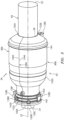
FIG. 3 is a side perspective illustration of a static engine structure for the gas turbine engine. -
FIG. 4 is an illustration of an aft end of the static engine structure. -
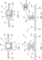
FIGS. 5-8 are sectional illustrations of various sealed joints between a first wall portion and a second wall portion. -
FIG. 9 is a sectional illustration of a mechanical connection between a first case segment and a second case segment. -
FIG. 10 is a schematic illustration of a manufacturing system. -
FIG. 11 is a flow diagram of a method for forming a gas turbine engine. -
FIG. 12 is a side sectional illustration of a static engine structure preform. -
FIGS. 13-15 are schematic illustrations of connections between adjacent case segment preforms. -
FIG. 1 is a side sectional illustration of agas turbine engine 20. Thegas turbine engine 20 ofFIG. 1 is configured as a single spool, radial-flow turboj et turbine engine. Thisgas turbine engine 20 is configured for propelling an aircraft such as, but not limited to, an unmanned aerial vehicle (UAV), a drone or any other manned or unmanned aircraft or self-propelled projectile. The present disclosure, however, is not limited to such an exemplary turbojet turbine engine configuration nor to an aircraft propulsion system application. For example, thegas turbine engine 20 may alternatively be configured as an auxiliary power unit (APU) or an industrial gas turbine engine. - The
gas turbine engine 20 ofFIG. 1 extends axially along anaxial centerline 22 between a forward,upstream airflow inlet 24 and an aft,downstream airflow exhaust 26. Thisaxial centerline 22 may also be a rotational axis for various components within thegas turbine engine 20. - The
gas turbine engine 20 includes acompressor section 28, acombustor section 30 and aturbine section 32. Thegas turbine engine 20 also includes astatic engine structure 34. Thisstatic engine structure 34 houses thecompressor section 28, thecombustor section 30 and theturbine section 32. Thestatic engine structure 34 ofFIG. 1 also forms aninlet section 36 and anexhaust section 38 for thegas turbine engine 20, where theinlet section 36 forms theairflow inlet 24 and theexhaust section 38 forms theairflow exhaust 26. - The
engine sections core flowpath 40 that extends through thegas turbine engine 20 from theairflow inlet 24 to theairflow exhaust 26. Each of theengine sections respective rotor rotors - The
compressor rotor 42 may be configured as a radial flow rotor. Theturbine rotor 44 may also or alternatively be configured as a radial flow rotor. Thecompressor rotor 42 is connected to theturbine rotor 44 through ashaft 46. Thisshaft 46 is rotatably supported by thestatic engine structure 34 through a plurality ofbearings - The
combustor section 30 includes anannular combustor 50 with anannular combustion chamber 52. Thecombustor 50 ofFIG. 1 is configured as a reverse flow combustor. Inlets ports /flow tubes 54 into thecombustion chamber 52, for example, may be arranged at (e.g., on, adjacent or proximate) and/or towards anaft bulkhead wall 56 of thecombustor 50. An outlet from thecombustor 50 may be arranged axially aft of an inlet to theturbine section 32. Thecombustor 50 may also be arranged radially outboard of and/or axially overlap at least a (e.g., aft) portion of theturbine section 32. With this arrangement, thecore flowpath 40 ofFIG. 1 reverses its directions (e.g., from a forward-to-aft direction to an aft-to-forward direction) a first time as theflowpath 40 extends from adiffuser plenum 58 surrounding thecombustor 50 into thecombustion chamber 52. The core flowpath 40 ofFIG. 1 then reverses its direction (e.g., from the aft-to-forward direction to the forward-to-aft direction) a second time as theflowpath 40 extends from thecombustion chamber 52 into theturbine section 32. - During operation, air enters the
gas turbine engine 20 through theinlet section 36 and itsairflow inlet 24. Theinlet section 36 directs this air from theairflow inlet 24 into thecore flowpath 40 and thecompressor section 28. Theairflow inlet 24 ofFIG. 1 thereby forms a forward, upstream inlet to thecore flowpath 40 and thecompressor section 28. The air within thecore flowpath 40 may be referred to as core air. - The core air is compressed by the
compressor rotor 42 and directed through adiffuser 60 and itsplenum 58 into thecombustion chamber 52. Fuel is injected and mixed with the compressed core air to provide a fuel-air mixture. This fuel-air mixture is ignited within thecombustion chamber 52, and combustion products thereof flow through theturbine section 32 and cause theturbine rotor 44 to rotate. This rotation of theturbine rotor 44 drives rotation of thecompressor rotor 42 and, thus, compression of the air received from theairflow inlet 24. Theexhaust section 38 receives the combustion products from theturbine section 32. Theexhaust section 38 directs the received combustion products out of thegas turbine engine 20 to provide forward engine thrust. - The
static engine structure 34 ofFIG. 1 may include some or all static engine components included in thegas turbine engine 20. Herein, the term static may describe a component that does not rotate with the rotating assembly (e.g., an assembly of therotors static engine structure 34 ofFIG. 1 , for example, includes a forward, splitcase structure 62 and an aft,exhaust duct structure 64. - The
split case structure 62 ofFIG. 2 is configured as a generally tubular structure. Thesplit case structure 62, for example, extends axially along theaxial centerline 22 from theforward airflow inlet 24 to anoutlet 66 from theturbine section 32. Thesplit case structure 62 also extends circumferentially about (e.g., completely around) theaxial centerline 22 such that thesplit case structure 62 has, for example, a full hoop geometry; see alsoFIGS. 3 and4 . - The
split case structure 62 includes one or more case walls. Thesplit case structure 62 ofFIG. 2 , for example, includes acompressor wall 68, adiffuser wall 70, anouter combustor wall 72 of thecombustor 50, aninner combustor wall 74 of thecombustor 50, thebulkhead wall 56 of thecombustor 50, anouter turbine wall 76 and aninner turbine wall 78. One or more or each of thesecase walls case walls FIG. 2 , for example, is tubular, and thebulkhead wall 56 is annular. - The
compressor wall 68 extends axially along theaxial centerline 22 between and is connected to theinlet section 36 and thediffuser wall 70. Thecompressor wall 68 ofFIG. 2 circumscribes, axially overlaps and thereby houses thecompressor rotor 42. - The
diffuser wall 70 extends axially along theaxial centerline 22 between and is connected to thecompressor wall 68 and an aft end portion of theinner turbine wall 78. Thediffuser wall 70 is spaced / displaced radially outboard from and axially overlaps thecombustor 50. Thediffuser wall 70 ofFIG. 2 thereby forms an outer peripheral boundary of thediffuser plenum 58 that surrounds thecombustor 50. - The
outer combustor wall 72 extends axially along theaxial centerline 22 between and may be connected to thebulkhead wall 56 and anouter platform 80 of anexit nozzle 82 from thecombustion chamber 52. Theinner combustor wall 74 is circumscribed and axially overlapped by theouter combustor wall 72. Theinner combustor wall 74 extends axially along theaxial centerline 22 between and may be connected to thebulkhead wall 56 and aninner platform 84 of theexit nozzle 82. Thebulkhead wall 56 extends radially between and is connected to aft end portions of theouter combustor wall 72 and theinner combustor wall 74. Thecase walls combustion chamber 52 therebetween. - The
outer turbine wall 76 may be connected to the exit nozzleouter platform 80. Theouter turbine wall 76 projects axially out from the exit nozzleouter platform 80 and extends axially towards / to an aft, downstream end of aninner platform 86 of thecompressor rotor 42. Thisouter turbine wall 76 is circumscribed and axially overlapped by thediffuser wall 70. Theouter turbine wall 76 ofFIG. 2 may thereby form an inner peripheral boundary of thecore flowpath 40 within thediffuser 60, and may form an outer peripheral boundary of thecore flowpath 40 within a (e.g., upstream) portion of theturbine section 32. Theouter turbine wall 76 ofFIG. 2 also circumscribes, axially overlaps and thereby houses a (e.g., upstream) portion of theturbine rotor 44. - The
inner turbine wall 78 may be connected to the exit nozzleinner platform 84. An upstream portion of theinner turbine wall 78 projects axially (in the aft-to-forward direction) out from the exit nozzleinner platform 84 to a turning portion of theinner turbine wall 78. A downstream portion of theinner turbine wall 78 projects axially (in the forward-to-aft direction) away from the inner turbine wall turning portion to theturbine section outlet 66. Theinner turbine wall 78 is circumscribed and axially overlapped by thecombustor 50. Theinner turbine wall 78 is also spaced / displaced radially inboard from thecombustor 50. Theinner turbine wall 78 ofFIG. 2 thereby forms an inner peripheral boundary of thediffuser plenum 58 that surrounds thecombustor 50. Theinner turbine wall 78 forms an outer peripheral boundary of thecore flowpath 40 within a (e.g., downstream) portion of theturbine section 32. Theinner turbine wall 78 ofFIG. 2 also circumscribes, axially overlaps and thereby houses a (e.g., downstream) portion of theturbine rotor 44. - The
static engine structure 34 may also include one or more internal support structures with one or more support members. Examples of support members include, but are not limited to, struts, structural guide vanes, bearing supports, bearing compartment walls, etc. Thestatic engine structure 34 ofFIG. 2 , for example, includes aforward support structure 88, anaft support structure 90, aninlet nozzle 92 and theexit nozzle 82. Theforward support structure 88 and theinlet nozzle 92 may be configured together. Theforward support structure 88 may be configured to support the forward bearing 48A. Theaft support structure 90 may be configured to support the aft bearing 48B. Theinlet nozzle 92 may be configured to condition the core air entering thecompressor section 28. Theinlet nozzle 92, for example, may include one ormore guide vanes 94 which impart swirl to the core air. Theexit nozzle 82 may similarly be configured to condition the combustion products exiting thecombustor section 30. Theexit nozzle 82, for example, may include one ormore guide vanes 96 which import swirl to the combustion products, where theseguide vanes 96 are connected to and extend radially between the exit nozzle inner andouter platforms static engine structure 34, of course, may also or alternative include various other static / stationary gas turbine engine components. - Referring now to
FIGS. 3 and4 , thesplit case structure 62 is configured from a plurality of discretesplit case segments split case structure 62 ofFIGS. 3 and4 , for example, at least or only includes afirst case segment 98A (e.g., a first side split case half) and asecond case segment 98B (e.g., a second side split case half). Referring toFIG. 3 , each of thecase segments axial centerline 22 between aforward end split case structure 62 and an axially opposingaft end split case structure 62, where theforward end airflow inlet 24 and/or theaft end turbine section outlet 66. Referring toFIG. 4 , each of thecase segments axial centerline 22 between afirst side respective case segment second side respective case segment - The
first side 104A of thefirst case segment 98A is arranged circumferentially adjacent thesecond side 106B of thesecond case segment 98B. Thefirst case segment 98A is connected (e.g., mechanically attached) to thesecond case segment 98B at an axially extending joint 108A between the first case segmentfirst side 104A and the second case segmentsecond side 106B. Similarly, thesecond side 106A of thefirst case segment 98A is arranged circumferentially adjacent thefirst side 104B of thesecond case segment 98B. Thefirst case segment 98A is connected (e.g., mechanically attached) to thesecond case segment 98B at an axially extending joint 108B between the first case segmentsecond side 106A and the second case segmentfirst side 104B. Therefore, when thecase segments 98 are arranged and connected together, thecase segments 98 collectively form thesplit case structure 62. - With the foregoing arrangement, during assembly of the
gas turbine engine 20 ofFIG. 1 , the bearings 48 may be mated with (e.g., mounted to) theshaft 46. The rotating assembly (e.g., 42, 44 and 46) with the bearings 48 may be mated with (e.g., seated in) one of thecase segments 98; e.g., thefirst case segment 98A ofFIGS. 3 and4 . The other one of the case segments 98 (e.g., thesecond case segment 98B ofFIGS. 3 and4 ) may thereafter be mated with thefirst case segment 98A to enclose the rotating assembly (e.g., 42, 44 and 46) and the bearings 48 within thesplit case structure 62. - Since the
case structure 62 is configured as a split case structure (e.g., includes thediscrete case segments 98 which are, for example, mechanically attached together), the entire rotating structure (e.g., 42, 44 and 46) may be placed laterally into thesplit case structure 62 as a single unit when thecase segments 98 are apart. The rotating structure (e.g., 42, 44 and 46) may therefore be formed as a single monolithic body. Thesplit case structure 62 may extend as a single unit between its opposing ends (e.g., between theinlet 24 and the outlet 66), rather than being pieced together from a plurality of axial case segments as in a prior art gas turbine engine application. Thecompressor rotor 42 and/or theturbine rotor 44 may be sized greater than a minimum diameter of thesplit case structure 62. By contrast, when a rotating assembly is slid / axially translated during the mating with a case segment, the maximum diameter of a rotor of the rotating assembly cannot be greater than a minimum diameter of a portion of the case segment where the rotor needs to travel axially into or through the case segment portion. In addition, thesplit case structure 62 may be additively manufactured (e.g., in a single process) within a build space of an additive manufacturing system as described below in further detail. - Referring to
FIG. 2 , each of thecase segments case walls support structures case segment 98 ofFIG. 2 , for example, is configured to form a respective portion (e.g., half) of thecompressor wall 68, a respective portion (e.g., half) of thediffuser wall 70, a respective portion (e.g., half) of theouter combustor wall 72, a respective portion (e.g., half) of theinner combustor wall 74, a respective portion (e.g., half) of thebulkhead wall 56, a respective portion (e.g., half) of theouter turbine wall 76, and a respective portion (e.g., half) of theinner turbine wall 78. Eachcase segment 98 ofFIG. 2 is also configured to form a respective portion (e.g., half) of theforward support structure 88, a respective portion (e.g., half) of theaft support structure 90, a respective portion (e.g., half) of theinlet nozzle 92, and a respective portion (e.g., half) of theexit nozzle 82. Thus, each of thecase segments 98 may form each part of thesplit case structure 62 in a corresponding portion (e.g., half) of thesplit case structure 62. Eachcase segment 98 may thereby form a static portion of one or more or each of theengine sections FIG. 1 ). - Each of the
case segments 98 may be formed as a monolithic body. Herein, the term monolithic may described an apparatus which is formed as a single unitary body. Eachcase segment 98, for example, may be additively manufactured, cast, machined and/or otherwise formed as an integral, unitary body. By contrast, a non-monolithic body may include parts that are discretely formed from one another, where those parts are subsequently mechanically fastened and/or otherwise attached to one another. - Referring to
FIGS. 5-8 , thefirst case segment 98A may be sealingly engaged with and/or otherwise mated with thesecond case segment 98B at one or each of thejoints FIG. 4 . Afirst wall portion 110A (e.g., any one of thewall FIG. 2 ) of one of the case segments 98 (e.g., thefirst case segment 98A or thesecond case segment 98B), for example, may be sealingly engaged with a respectivesecond wall portion 110B (e.g., any one of thewall FIG. 2 ) of another one of the case segments 98 (e.g., thesecond case segment 98B or thefirst case segment 98A) at the respective joint 108. Various types of sealed joints / interfaces are shown inFIGS. 5-8 . The present disclosure, however, is not limited to any of these exemplary sealed joints / interfaces. Furthermore, it is contemplated that the seal joint between portions of one wall may be the same or different than the seal joint between portions of another one or more of the walls of the samesplit case structure 62. - Referring to
FIG. 5 , in some embodiments, thefirst wall portion 110A includes a (e.g., female) first mountingcoupler 112A configured with anaxially extending channel 114. Thischannel 114 extends laterally (e.g., circumferentially or tangentially) into thefirst wall portion 110A from a respective side to a blind end formed by achannel end surface 116. Thechannel 114 extends radially within thefirst wall portion 110A between opposing channel side surfaces 118 and 120. Thesecond wall portion 110B includes a (e.g., male) second mountingcoupler 112B configured with aseal element 122. Examples of theseal element 122 may include, but are not limited to, a C-seal element, a U-seal element, a V-seal element and a W-seal element. Theseal element 122 is configured to be inserted within / project into thechannel 114 and sealing engage the first mountingcoupler 112A. For example, when thecase segments couplers seal element 122 is pushed and/or compressed within thechannel 114 and against any one or more or each of the channel surfaces 116, 118 and/or 120. The mountingcouplers first wall portion 110A and the second wall portion 11 0B at therespective j oint 108. - Referring to
FIG. 6 , in some embodiments, thesplit case structure 62 further includes at least one seal element 124, which seal element 124 may be discrete from or attached to one of thewall portions first wall portion 110A includes the (e.g., female) first mountingcoupler 112A. Thesecond wall portion 110B includes a (e.g., male) second mountingcoupler 112C. Thesecond mounting coupler 112C is configured to be inserted within / project into thechannel 114 and sealing engage the first mountingcoupler 112A through at least the seal element 124. The sealing element 124, for example, may be arranged between and pressed, compressed and/or crushed against one or more of the channel surfaces (e.g., thesurfaces 116 and 118) and achamfered end surface 126 of thesecond mounting coupler 112C. The mountingcouplers first wall portion 110A and thesecond wall portion 110B at the respective joint 108. - Referring to
FIG. 7 , in some embodiments, thesplit case structure 62 further includes at least oneseal element 128, whichseal element 128 may be discrete from or attached to one of thewall portions seal element 128 is, but is not limited to, a flat face seal gasket. Such a flat face seal gasket may be constructed from material such as, but not limited to, Grafoil® material (produced by Neograf Solutions, LLC in Ohio, United States) for high temperature applications. The present disclosure, however, is not limited to the foregoing exemplary seal material. Thefirst wall portion 110A includes a first mountingflange 130A and thesecond wall portion 110B includes asecond mounting flange 130B. Theseal element 128 is arranged (e.g., sandwiched) between the mountingflanges flanges more fasteners 132; e.g., bolts, studs, etc. Theflanges seal element 128 may thereby seal the interface between thefirst wall portion 110A and thesecond wall portion 110B at the respective joint 108. - Referring to
FIG. 8 , in some embodiments, thesplit case structure 62 further includes at least oneseal element 134, whichseal element 134 may be discrete from or attached to or formed integral with one of thewall portions seal element 134 may be a deformable (e.g., crushable) seal element. Theseal element 134 ofFIG. 8 , for example, is configured from a network (e.g., a truss system and/or lattice) ofwebs 136. Thesewebs 136 are arranged such that theseal element 134 may be laterally (e.g., circumferentially and/or tangentially) compressed / crushed. The interstices (e.g., apertures) between thewebs 136 may also or alternatively provide a scaffold for a bonding adhesive and/or a ceramic compound (e.g., thermal isolating material). Alternatively, at least some or all of the interstices may be empty. Thefirst wall portion 110A includes the first mountingflange 130A and thesecond wall portion 110B includes the second mountingflange 130B. Theseal element 134 is arranged (e.g., sandwiched) between the mountingflanges flanges fasteners 132 inFIG. 7 ). Theflanges seal element 134 may thereby seal the interface between thefirst wall portion 110A and thesecond wall portion 110B at the respective joint 108. - Referring to
FIG. 9 , one or more respective sets ofwall portions exterior walls wall portions FIG. 9 , for example, are attached together by a bolted flange connection. However, one or moreother wall portions interior walls FIGS. 5 and 6 ); e.g., by sealed slip joints, sealed male-female (e.g., tongue and groove) joints, etc. - Referring again to
FIG. 1 , theexhaust duct structure 64 is configured as a tubular body that extends axially along and circumferentially about (e.g., completely around) theaxial centerline 22. A forward, upstream end portion of theexhaust duct structure 64 is nested within and mounted with theinner turbine wall 78 at theturbine section outlet 66. An aft, downstream portion of theexhaust duct structure 64 forms theairflow exhaust 26. Thisexhaust duct structure 64 may be formed as a single tubular monolithic body; however, the present disclosure is not limited to such an exemplary configuration. - In some embodiments, referring to
FIG. 3 , one or more of thecase segments 98 may include one or more additional features. Examples of these additional features include, but are not limited to,bosses 138A-F, mount 140,reinforcements 142A-D (e.g., ribs, stiffeners, etc.), and fluid passage 144 (e.g., conduit). In general, the additional features are configured to avoid or minimize overlapping / crossing thejoints 108 between thecase segments 98. For example, any one or more or all of the features may be completely configured with a single one of the case segments; e.g., 98A or 98B. However, in some embodiments, one or more of the additional features (e.g., theboss 138F, thereinforcements 142A-D, the conduit 144) may extend across at least one of thejoints 108 between thecase segments 98. -
FIG. 10 illustrates asystem 146 for manufacturing a static engine structure such as, but not limited to, thestatic engine structure 34 ofFIG. 1 . This manufacturing system 146 (e.g., an additive manufacturing system) includes abuild chamber 148 defining abuild space 150 for manufacturing the static engine structure 34 (or one or more of its components). Themanufacturing system 146 also includes anadditive manufacturing apparatus 152; e.g., a laser powder bed fusion (LPBF) apparatus. - The
additive manufacturing apparatus 152 is configured to build the static engine structure 34 (or one or more of its components) or a preform thereof within thebuild space 150 in a layer-by-layer fashion. For example, theadditive manufacturing apparatus 152 may deposit a first layer ofpowder 154A over asupport surface 156 within thebuild space 150. Theadditive manufacturing apparatus 152 may thereafter selectively solidify (e.g., sinter) a select portion of the first layer ofpowder 154A to form afirst portion 158A (e.g., layer, slice) of the static engine structure 34 (or one or more of its components) or a preform thereof. Theadditive manufacturing apparatus 152 may deposit a second layer ofpowder 154B within thebuild space 150 over the first layer of at least partially solidifiedpowder 154A. Theadditive manufacturing apparatus 152 may thereafter selectively solidify a select portion of the second layer ofpowder 154B with the previously solidifiedfirst portion 158A to form asecond portion 158B (e.g., layer, slice) of the static engine structure 34 (or one or more of its components) or a preform thereof. This process may be repeated until the entire static engine structure 34 (or one or more of its components) or a preform thereof is formed. - While the
additive manufacturing apparatus 152 is described above as a laser powder bed fusion (LPBF) apparatus, the present disclosure is not limited thereto. Theadditive manufacturing apparatus 152, for example, may alternatively be configured as a stereolithography (SLA) apparatus, a direct selective laser sintering (DSLS) apparatus, an electron beam sintering (EBS) apparatus, an electron beam melting (EBM) apparatus, a laser engineered net shaping (LENS) apparatus, a laser net shape manufacturing (LNSM) apparatus, a direct metal deposition (DMD) apparatus or a direct metal laser sintering (DMLS) apparatus. -
FIG. 11 is a flow diagram of amethod 1100 for manufacturing an engine such as, but not limited to, the gas turbine engine 20 (or one or more of its components) ofFIG. 1 . Thismethod 1100 may be performed using a manufacturing system such as, but not limited to, themanufacturing system 146 ofFIG. 10 . - In
step 1102, a staticengine structure preform 160 is formed. An example of the staticengine structure preform 160 is shown inFIG. 12 . This staticengine structure preform 160 includes a firstcase segment preform 162A and a secondcase segment preform 162B. The staticengine structure preform 160 may also include an exhaustduct structure preform 164 nested within the case segment preforms 162A and 162B. - Herein, the term preform may describe a body having at least a basic configuration (e.g., shape, size, features, etc.) of a part to be formed. For example, the first
case segment preform 162A may generally have the same configuration as thefirst case segment 98A to be formed (seeFIGS. 1-3 ). However, the firstcase segment preform 162A may include one or more build features, one or more unfinished surfaces, etc. The build features (e.g., webs, ribs, spares, etc.) may be included in order to support the preform during theformation step 1102. These build features, however, are removed (e.g., via machining) after theformation step 1102 to provide thefirst case segment 98A. In addition or alternatively, one or more surfaces, features (e.g., apertures, bosses, mounting features), etc. of the firstcase segment preform 162A may be machined (e.g., refined, smoothed, drilled, etc.) to provide thefirst case segment 98A. Generally speaking, no additional material will need to be added to the first case segment preform 162A to provide thefirst case segment 98A following theformation step 1102. - The static
engine structure preform 160 may be completely formed within thebuild space 150 of theadditive manufacturing apparatus 152. The entire staticengine structure preform 160 including each of itscomponents build space 150. - The first
case segment preform 162A may be formed as a discrete body from the secondcase segment preform 162B. The firstcase segment preform 162A, for example, may be laterally separated from the secondcase segment preform 162B by a lateral gap. Alternatively, referring toFIGS. 13 to 15 , the firstcase segment preform 162A may be formed integral with and thereby connected to the secondcase segment preform 162B. For example, referring toFIG. 13 , the firstcase segment preform 162A may be indirectly connected to the secondcase segment preform 162B by one or moreintermediate bridge structures 166. Each of thesebridge structures 166 extends between and is connected (e.g., directly) to the firstcase segment preform 162A and the secondcase segment preform 162B at theirsides bridge structures 166 may have a V-shape, a U-shape, a chevron shape, etc. with a sharp chamfer or a radiused (e.g., eased, rounded) chamfer (e.g., seeFIG. 14 ). Alternatively, referring toFIG. 15 , the firstcase segment preform 162A may be connected directly to the secondcase segment preform 162B. - Referring again to
FIG. 12 , the exhaustduct structure preform 164 may be formed as a discrete body from one or each of the case segment preforms 162A and/or 162B. The present disclosure, however, is not limited to such a formation technique. For example, in other embodiments, the exhaustduct structure preform 164 may be connected to one or more of the case segment preforms 162A and/or 162B by one or more build supports (e.g., similar to thebridge structures 166 inFIGS. 13 or 14 ). - While the components of the static
engine structure preform 160 are described above as being formed concurrently within thebuild space 150, the present disclosure is not limited thereto. For example, in other embodiments, each of the preforms 162A, 162B, 164 (or select ones of the preforms) may be formed within thebuild space 150 separately from another one or more of the preforms 162A, 162B, 164. Furthermore, while theformation step 1102 is described above in relation to additively manufacturing, the present disclosure is not limited thereto. For example, in other embodiments, one or more or each of the preforms 162A, 162B and/or 164 may also or alternatively be formed using casting, machining and/or various other manufacturing techniques. - In
step 1104, thestatic engine structure 34 and itscomponents build space 150 of themanufacturing system 146. In addition (before or after being removed from the build space 150), one or more of the following operations may be performed: - ▪ One or more or each of the preforms 162A, 162B and/or 164 may be de-powdered. For example, any remaining, un-solidified powder trapped with a
respective preform - ▪ The
preforms preforms FIGS. 13 to 15 . For example, thebridge structures 166 ofFIG. 13, 14 may be cut off and/or ground down to separate the case segment preforms 162A and 162B. Alternatively, referring toFIG. 15 , the combined case segment preform may be cut along acut line 170 to providediscrete preform segments - ▪ Any build features may be removed from one or more or each of the preforms 162A, 162B and/or 164.
- ▪ One or more surfaces, one or more features, etc. of one or more of the preforms 162A, 162B and/or 164 may be machined, surface treated, heat treated, etc.
- ▪ One or more surfaces of one or more of the preforms 162A, 162B and/or 164 may be cleaned.
- ▪ One or more surfaces of one or more of the preforms 162A, 162B and/or 164 may be coated.
- In
step 1106, the rotating assembly (e.g., 42, 44 and 46) and the bearings 48 are installed with one of the case segments 98 (e.g., thefirst case segment 98A). - In step 1108, the
exhaust duct structure 64 is installed with the one of the case segments 98 (e.g., thefirst case segment 98A). - In
step 1110, the remaining case segment 98 (e.g., thesecond case segment 98B) is mated with the other case segment 98 (e.g., thefirst case segment 98A) to provide thegas turbine engine 20. - The
gas turbine engine 20 is described above as a single spool, radial-flow turbojet turbine engine for ease of description. The present disclosure, however, is not limited to such an exemplary gas turbine engine. Thegas turbine engine 20, for example, may alternatively be configured as an axial flow gas turbine engine. Thegas turbine engine 20 may be configured as a direct drive gas turbine engine. Thegas turbine engine 20 may alternatively include a gear train that connects one or more rotors together such that the rotors rotate at different speeds. Thegas turbine engine 20 may be configured with a single spool (e.g., seeFIG. 1 ), two spools, or with more than two spools. Thegas turbine engine 20 may be configured as a turbofan engine, a turbojet engine, a propfan engine, a pusher fan engine or any other type of turbine engine. In addition, while thegas turbine engine 20 is described above with an exemplary reverser flow annular combustor, thegas turbine engine 20 may also or alternatively include any other type / configuration of annular, tubular (e.g., CAN), axial flow and/or reverser flow combustor. The present disclosure therefore is not limited to any particular types or configurations of turbine engines. - While various embodiments of the present invention have been described above, it will be apparent to those of ordinary skill in the art that many more embodiments and implementations are possible within the scope of the disclosure as defined by the claims. For example, the present invention as described herein includes several aspects and embodiments that include particular features. Although these features may be described individually, it is within the scope of the present invention that some or all of these features may be combined with any one of the aspects and remain within the scope of the invention. Accordingly, the present invention is not to be restricted except in light of the attached claims and their equivalents.
Claims (15)
- An assembly for a gas turbine engine (20), comprising:a split case structure (62) including a first wall (56), a second wall (56), a first case segment (98A) and a second case segment (98B);the first wall (56) extending axially along and circumferentially about an axial centerline (22);the second wall (56) extending axially along and circumferentially about the axial centerline (22), and the second wall (56) radially outboard of and axially overlapping the first wall (56);the first case segment (98A) configured to form a first portion (158A) of the first wall (56) and a first portion (158A) of the second wall (56); andthe second case segment (98B) configured to form a second portion (158B) of the first wall (56) and a second portion (158B) of the second wall (56), and the second case segment (98B) circumferentially adjacent and attached to the first case segment (98A) at a joint (108).
- The assembly of claim 1, wherein:the first case segment (98A) is configured as a monolithic body; andthe second case segment (98B) is configured as a monolithic body.
- The assembly of claim 1 or 2, wherein one of the first wall (56) and the second wall (56) comprises a diffuser wall (70).
- The assembly of claim 1 or 2, wherein one of the first wall (56) and the second wall (56) comprises a combustor (50) wall (56).
- The assembly of claim 1 or 2, wherein one of the first wall (56) and the second wall (56) comprises a compressor wall (68).
- The assembly of claim 1 or 2, wherein one of the first wall (56) and the second wall (56) comprises a turbine wall (56).
- The assembly of any preceding claim, wherein the first case segment (98A) includes a support member that extends between and connects the first wall (56) to the second wall (56).
- The assembly of any preceding claim, wherein:the first case segment (98A) includes a channel (114); andthe second case segment (98B) includes a seal element (122; 124; 128; 134) inserted within the channel (114) to seal an interface between the first case segment (98A) and the second case segment (98B) at the joint (108).
- The assembly of any preceding claim, wherein the split case structure (62) further includes a seal element (122; 124; 128; 134) arranged between and engaged with the first case segment (98A) and the second case segment (98B) to seal an interface between the first case segment (98A) and the second case segment (98B) at the joint (108).
- The assembly of any preceding claim, wherein the first case segment (98A) includes a crush seal element (122; 124; 128; 134) configured to engage the second case segment (98B) to seal an interface between the first case segment (98A) and the second case segment (98B) at the joint (108).
- The assembly of any preceding claim, wherein:the split case structure (62) forms a compressor section (28) inlet (24) and a turbine section outlet (66); andthe first case segment (98A) extends axially along the axial centerline (22) from the compressor section (28) inlet (24) to the turbine section outlet (66).
- The assembly of claim 11, wherein the second case segment (98B) extends axially along the axial centerline (22) from the compressor section (28) inlet (24) to the turbine section outlet (66).
- An assembly for a gas turbine engine (20), comprising:a split case structure (62) for the gas turbine engine (20), the split case structure (62) including a compressor wall (68), a combustor (50) wall (56), a turbine wall (56), a first case segment (98A) and a second case segment (98B);the first case segment (98A) is configured to form a first portion (158A) of the compressor wall (68), a first portion (158A) of the combustor (50) wall (56) and a first portion (158A) of the turbine wall (56); andthe second case segment (98B) configured to form a second portion (158B) of the compressor wall (68), a second portion (158B) of the combustor (50) wall (56) and a second portion (158B) of the turbine wall (56).
- The assembly of claim 13, wherein at least one ofthe first case segments (98A) forms a respective portion of an inlet (24) to a compressor section (28) of the gas turbine engine (20); orthe first case segments (98A) forms a respective portion of an outlet (66) from a turbine section (32) of the gas turbine engine (20).
- The assembly of claim 13 or 14, whereinthe split case structure (62) includes a first wall (56) and a second wall (56) radially outboard of and axially overlapping the first wall (56);the first case segment (98A) is configured to form a first portion (158A) of the first wall (56) and a first portion (158A) of the second wall (56); andthe second case segment (98B) is configured to form a second portion (158B) of the first wall (56) and a second portion (158B) of the second wall (56).
Applications Claiming Priority (2)
| Application Number | Priority Date | Filing Date | Title |
|---|---|---|---|
| US17/085,494 US11614002B2 (en) | 2020-10-30 | 2020-10-30 | Split case structure for a gas turbine engine |
| EP21205603.0A EP3992439B1 (en) | 2020-10-30 | 2021-10-29 | Manufacturing method of a split case structure for a gas turbine engine |
Related Parent Applications (2)
| Application Number | Title | Priority Date | Filing Date |
|---|---|---|---|
| EP21205603.0A Division-Into EP3992439B1 (en) | 2020-10-30 | 2021-10-29 | Manufacturing method of a split case structure for a gas turbine engine |
| EP21205603.0A Division EP3992439B1 (en) | 2020-10-30 | 2021-10-29 | Manufacturing method of a split case structure for a gas turbine engine |
Publications (2)
| Publication Number | Publication Date |
|---|---|
| EP4410453A2 true EP4410453A2 (en) | 2024-08-07 |
| EP4410453A3 EP4410453A3 (en) | 2024-09-25 |
Family
ID=78414532
Family Applications (2)
| Application Number | Title | Priority Date | Filing Date |
|---|---|---|---|
| EP24183135.3A Pending EP4410453A3 (en) | 2020-10-30 | 2021-10-29 | Manufacturing method of a split case structure for a gas turbine engine |
| EP21205603.0A Active EP3992439B1 (en) | 2020-10-30 | 2021-10-29 | Manufacturing method of a split case structure for a gas turbine engine |
Family Applications After (1)
| Application Number | Title | Priority Date | Filing Date |
|---|---|---|---|
| EP21205603.0A Active EP3992439B1 (en) | 2020-10-30 | 2021-10-29 | Manufacturing method of a split case structure for a gas turbine engine |
Country Status (2)
| Country | Link |
|---|---|
| US (2) | US11614002B2 (en) |
| EP (2) | EP4410453A3 (en) |
Families Citing this family (3)
| Publication number | Priority date | Publication date | Assignee | Title |
|---|---|---|---|---|
| US11512611B2 (en) * | 2021-02-09 | 2022-11-29 | General Electric Company | Stator apparatus for a gas turbine engine |
| US12385407B1 (en) | 2024-05-17 | 2025-08-12 | Rtx Corporation | Additively manufactured turbine vane cluster |
| US20260015945A1 (en) | 2024-07-09 | 2026-01-15 | Rtx Corporation | Diffuser-turbine flow network |
Citations (1)
| Publication number | Priority date | Publication date | Assignee | Title |
|---|---|---|---|---|
| US10184357B2 (en) * | 2016-02-08 | 2019-01-22 | General Electric Company | Lift device for turbine casing and method to lift the casing |
Family Cites Families (29)
| Publication number | Priority date | Publication date | Assignee | Title |
|---|---|---|---|---|
| US3641766A (en) * | 1969-11-26 | 1972-02-15 | Gen Electric | Gas turbine engine constant speed thrust modulation |
| US3741680A (en) * | 1972-04-05 | 1973-06-26 | Avco Corp | Split housing piloting device |
| US3764226A (en) * | 1972-04-05 | 1973-10-09 | Avco Corp | Piloting device for split housings having different thermal coefficients of expansion |
| US4208777A (en) * | 1978-11-27 | 1980-06-24 | United Technologies Corporation | Method for manufacturing a split engine casing from a cylinder |
| US4825640A (en) * | 1987-06-22 | 1989-05-02 | Sundstrand Corporation | Combustor with enhanced turbine nozzle cooling |
| US5237817A (en) * | 1992-02-19 | 1993-08-24 | Sundstrand Corporation | Gas turbine engine having low cost speed reduction drive |
| US5639212A (en) * | 1996-03-29 | 1997-06-17 | General Electric Company | Cavity sealed compressor |
| US6134779A (en) * | 1998-11-16 | 2000-10-24 | Walker; Bruce K. | High performance forged aluminum connecting rod and method of making the same |
| US6352404B1 (en) * | 2000-02-18 | 2002-03-05 | General Electric Company | Thermal control passages for horizontal split-line flanges of gas turbine engine casings |
| US6345441B1 (en) * | 2000-07-18 | 2002-02-12 | General Electric Company | Method of repairing combustion chamber liners |
| US7194866B1 (en) * | 2003-06-20 | 2007-03-27 | Hamilton Sundstrand Corporation | Static structure for an expendable gas turbine engine |
| DE602004014154D1 (en) * | 2003-07-29 | 2008-07-10 | Pratt & Whitney Canada | Turbofan engine casing, turbofan engine and corresponding process |
| US8387357B2 (en) * | 2008-08-12 | 2013-03-05 | Pratt & Whitney | Recuperated bypass turbine engine |
| US8128353B2 (en) * | 2008-09-30 | 2012-03-06 | General Electric Company | Method and apparatus for matching the thermal mass and stiffness of bolted split rings |
| US8511971B2 (en) * | 2010-07-23 | 2013-08-20 | Hamilton Sundstrand Corporation | One-piece compressor and turbine containment system |
| US9039364B2 (en) | 2011-06-29 | 2015-05-26 | United Technologies Corporation | Integrated case and stator |
| US8784041B2 (en) * | 2011-08-31 | 2014-07-22 | Pratt & Whitney Canada Corp. | Turbine shroud segment with integrated seal |
| US9127558B2 (en) * | 2012-08-01 | 2015-09-08 | General Electric Company | Turbomachine including horizontal joint heating and method of controlling tip clearance in a gas turbomachine |
| US20140035240A1 (en) | 2012-08-03 | 2014-02-06 | General Electric Company | Sliding seal for sealing a joint in a turbine casing and method for sealing |
| WO2014201247A1 (en) * | 2013-06-14 | 2014-12-18 | United Technologies Corporation | Heat shield assembly with double lap joint for a gas turbine engine |
| US8876448B1 (en) * | 2013-08-28 | 2014-11-04 | General Electric Company | Gas turbine half-casing shipping fixture |
| US10711702B2 (en) * | 2015-08-18 | 2020-07-14 | General Electric Company | Mixed flow turbocore |
| US9964040B2 (en) | 2015-09-30 | 2018-05-08 | Siemens Energy, Inc. | Spiral cooling of combustor turbine casing aft plenum |
| US10487943B2 (en) * | 2016-07-12 | 2019-11-26 | United Technologies Corporation | Multi-ply seal ring |
| US11156156B2 (en) | 2018-10-04 | 2021-10-26 | Raytheon Technologies Corporation | Gas turbine engine with a unitary structure and method for manufacturing the same |
| US11073033B2 (en) | 2018-10-18 | 2021-07-27 | Honeywell International Inc. | Stator attachment system for gas turbine engine |
| EP3712380A1 (en) | 2019-03-19 | 2020-09-23 | MTU Aero Engines GmbH | A component for an aero engine, an aero engine module comprising such a component, and method of manufacturing said component by additive manufacturing |
| US11761379B2 (en) * | 2019-07-23 | 2023-09-19 | Transportation Ip Holdings, Llc | System for a combined turbine, compressor, shroud, and bearing case for a turbocharger |
| US11732610B2 (en) * | 2021-11-24 | 2023-08-22 | Raytheon Technologies Corporation | Sectioned engine structure for a gas turbine engine |
-
2020
- 2020-10-30 US US17/085,494 patent/US11614002B2/en active Active
-
2021
- 2021-10-29 EP EP24183135.3A patent/EP4410453A3/en active Pending
- 2021-10-29 EP EP21205603.0A patent/EP3992439B1/en active Active
-
2023
- 2023-03-27 US US18/126,774 patent/US20230407767A1/en active Pending
Patent Citations (1)
| Publication number | Priority date | Publication date | Assignee | Title |
|---|---|---|---|---|
| US10184357B2 (en) * | 2016-02-08 | 2019-01-22 | General Electric Company | Lift device for turbine casing and method to lift the casing |
Also Published As
| Publication number | Publication date |
|---|---|
| US11614002B2 (en) | 2023-03-28 |
| US20230407767A1 (en) | 2023-12-21 |
| EP3992439A1 (en) | 2022-05-04 |
| EP3992439B1 (en) | 2024-08-28 |
| EP4410453A3 (en) | 2024-09-25 |
| US20220136409A1 (en) | 2022-05-05 |
Similar Documents
| Publication | Publication Date | Title |
|---|---|---|
| US20230407767A1 (en) | Split case structure for a gas turbine engine | |
| EP4632196A2 (en) | Assembly for a gas turbine engine and manufacturing method | |
| EP4331994B1 (en) | Vehicle component with integrated engine support structure and body section | |
| CA3054006A1 (en) | Cowl integration to combustor wall | |
| EP4343134A2 (en) | Gas turbine engine with integral bypass duct | |
| US12264624B2 (en) | Build plate integrated into additive manufactured component | |
| EP4528078A2 (en) | Multi-material flowpath wall for turbine engine | |
| US12398662B2 (en) | Gas turbine engine support structure with internal lattice | |
| US12385407B1 (en) | Additively manufactured turbine vane cluster | |
| EP4715185A1 (en) | Additively manufactured annular fuel manifold | |
| EP4481160A1 (en) | Support structure for forming turbine engine rotating structure | |
| EP4715184A1 (en) | Flow assisted integral splash plate | |
| EP4678901A2 (en) | Gas turbine engine with integral actuation system | |
| US12618380B2 (en) | Variable area nozzle for an aircraft engine | |
| EP4685341A1 (en) | Diffuser-turbine flow network | |
| US20260102859A1 (en) | Repairing seal land(s) for turbine engine component | |
| US20250334086A1 (en) | Variable area nozzle for an aircraft engine |
Legal Events
| Date | Code | Title | Description |
|---|---|---|---|
| PUAI | Public reference made under article 153(3) epc to a published international application that has entered the european phase |
Free format text: ORIGINAL CODE: 0009012 |
|
| STAA | Information on the status of an ep patent application or granted ep patent |
Free format text: STATUS: THE APPLICATION HAS BEEN PUBLISHED |
|
| AC | Divisional application: reference to earlier application |
Ref document number: 3992439 Country of ref document: EP Kind code of ref document: P |
|
| AK | Designated contracting states |
Kind code of ref document: A2 Designated state(s): AL AT BE BG CH CY CZ DE DK EE ES FI FR GB GR HR HU IE IS IT LI LT LU LV MC MK MT NL NO PL PT RO RS SE SI SK SM TR |
|
| REG | Reference to a national code |
Ref country code: DE Ref legal event code: R079 Free format text: PREVIOUS MAIN CLASS: B22F0005000000 Ipc: F01D0025240000 |
|
| PUAL | Search report despatched |
Free format text: ORIGINAL CODE: 0009013 |
|
| AK | Designated contracting states |
Kind code of ref document: A3 Designated state(s): AL AT BE BG CH CY CZ DE DK EE ES FI FR GB GR HR HU IE IS IT LI LT LU LV MC MK MT NL NO PL PT RO RS SE SI SK SM TR |
|
| RIC1 | Information provided on ipc code assigned before grant |
Ipc: B22F 5/00 20060101ALI20240821BHEP Ipc: B33Y 80/00 20150101ALI20240821BHEP Ipc: F01D 25/26 20060101ALI20240821BHEP Ipc: F01D 25/24 20060101AFI20240821BHEP |
|
| STAA | Information on the status of an ep patent application or granted ep patent |
Free format text: STATUS: REQUEST FOR EXAMINATION WAS MADE |
|
| 17P | Request for examination filed |
Effective date: 20250325 |
|
| STAA | Information on the status of an ep patent application or granted ep patent |
Free format text: STATUS: EXAMINATION IS IN PROGRESS |
|
| 17Q | First examination report despatched |
Effective date: 20260309 |