EP4410326A1 - Dialysis solution extraction device and blood purification device - Google Patents
Dialysis solution extraction device and blood purification device Download PDFInfo
- Publication number
- EP4410326A1 EP4410326A1 EP22883624.3A EP22883624A EP4410326A1 EP 4410326 A1 EP4410326 A1 EP 4410326A1 EP 22883624 A EP22883624 A EP 22883624A EP 4410326 A1 EP4410326 A1 EP 4410326A1
- Authority
- EP
- European Patent Office
- Prior art keywords
- dialysate
- collecting part
- projection
- dialysate extraction
- flow
- Prior art date
- Legal status (The legal status is an assumption and is not a legal conclusion. Google has not performed a legal analysis and makes no representation as to the accuracy of the status listed.)
- Pending
Links
Images






Classifications
-
- A—HUMAN NECESSITIES
- A61—MEDICAL OR VETERINARY SCIENCE; HYGIENE
- A61M—DEVICES FOR INTRODUCING MEDIA INTO, OR ONTO, THE BODY; DEVICES FOR TRANSDUCING BODY MEDIA OR FOR TAKING MEDIA FROM THE BODY; DEVICES FOR PRODUCING OR ENDING SLEEP OR STUPOR
- A61M1/00—Suction or pumping devices for medical purposes; Devices for carrying-off, for treatment of, or for carrying-over, body-liquids; Drainage systems
- A61M1/14—Dialysis systems; Artificial kidneys; Blood oxygenators ; Reciprocating systems for treatment of body fluids, e.g. single needle systems for hemofiltration or pheresis
- A61M1/16—Dialysis systems; Artificial kidneys; Blood oxygenators ; Reciprocating systems for treatment of body fluids, e.g. single needle systems for hemofiltration or pheresis with membranes
- A61M1/1654—Dialysates therefor
- A61M1/1656—Apparatus for preparing dialysates
-
- A—HUMAN NECESSITIES
- A61—MEDICAL OR VETERINARY SCIENCE; HYGIENE
- A61M—DEVICES FOR INTRODUCING MEDIA INTO, OR ONTO, THE BODY; DEVICES FOR TRANSDUCING BODY MEDIA OR FOR TAKING MEDIA FROM THE BODY; DEVICES FOR PRODUCING OR ENDING SLEEP OR STUPOR
- A61M1/00—Suction or pumping devices for medical purposes; Devices for carrying-off, for treatment of, or for carrying-over, body-liquids; Drainage systems
- A61M1/34—Filtering material out of the blood by passing it through a membrane, i.e. hemofiltration or diafiltration
- A61M1/342—Adding solutions to the blood, e.g. substitution solutions
- A61M1/3424—Substitution fluid path
- A61M1/3437—Substitution fluid path downstream of the filter, e.g. post-dilution with filtrate
-
- A—HUMAN NECESSITIES
- A61—MEDICAL OR VETERINARY SCIENCE; HYGIENE
- A61M—DEVICES FOR INTRODUCING MEDIA INTO, OR ONTO, THE BODY; DEVICES FOR TRANSDUCING BODY MEDIA OR FOR TAKING MEDIA FROM THE BODY; DEVICES FOR PRODUCING OR ENDING SLEEP OR STUPOR
- A61M1/00—Suction or pumping devices for medical purposes; Devices for carrying-off, for treatment of, or for carrying-over, body-liquids; Drainage systems
- A61M1/14—Dialysis systems; Artificial kidneys; Blood oxygenators ; Reciprocating systems for treatment of body fluids, e.g. single needle systems for hemofiltration or pheresis
- A61M1/16—Dialysis systems; Artificial kidneys; Blood oxygenators ; Reciprocating systems for treatment of body fluids, e.g. single needle systems for hemofiltration or pheresis with membranes
- A61M1/168—Sterilisation or cleaning before or after use
-
- A—HUMAN NECESSITIES
- A61—MEDICAL OR VETERINARY SCIENCE; HYGIENE
- A61M—DEVICES FOR INTRODUCING MEDIA INTO, OR ONTO, THE BODY; DEVICES FOR TRANSDUCING BODY MEDIA OR FOR TAKING MEDIA FROM THE BODY; DEVICES FOR PRODUCING OR ENDING SLEEP OR STUPOR
- A61M1/00—Suction or pumping devices for medical purposes; Devices for carrying-off, for treatment of, or for carrying-over, body-liquids; Drainage systems
- A61M1/34—Filtering material out of the blood by passing it through a membrane, i.e. hemofiltration or diafiltration
- A61M1/342—Adding solutions to the blood, e.g. substitution solutions
- A61M1/3455—Substitution fluids
- A61M1/3465—Substitution fluids using dialysate as substitution fluid
-
- A—HUMAN NECESSITIES
- A61—MEDICAL OR VETERINARY SCIENCE; HYGIENE
- A61M—DEVICES FOR INTRODUCING MEDIA INTO, OR ONTO, THE BODY; DEVICES FOR TRANSDUCING BODY MEDIA OR FOR TAKING MEDIA FROM THE BODY; DEVICES FOR PRODUCING OR ENDING SLEEP OR STUPOR
- A61M39/00—Tubes, tube connectors, tube couplings, valves, access sites or the like, specially adapted for medical use
- A61M39/10—Tube connectors; Tube couplings
- A61M39/16—Tube connectors; Tube couplings having provision for disinfection or sterilisation
- A61M39/165—Shrouds or protectors for aseptically enclosing the connector
-
- A—HUMAN NECESSITIES
- A61—MEDICAL OR VETERINARY SCIENCE; HYGIENE
- A61M—DEVICES FOR INTRODUCING MEDIA INTO, OR ONTO, THE BODY; DEVICES FOR TRANSDUCING BODY MEDIA OR FOR TAKING MEDIA FROM THE BODY; DEVICES FOR PRODUCING OR ENDING SLEEP OR STUPOR
- A61M39/00—Tubes, tube connectors, tube couplings, valves, access sites or the like, specially adapted for medical use
- A61M39/20—Closure caps or plugs for connectors or open ends of tubes
-
- A—HUMAN NECESSITIES
- A61—MEDICAL OR VETERINARY SCIENCE; HYGIENE
- A61M—DEVICES FOR INTRODUCING MEDIA INTO, OR ONTO, THE BODY; DEVICES FOR TRANSDUCING BODY MEDIA OR FOR TAKING MEDIA FROM THE BODY; DEVICES FOR PRODUCING OR ENDING SLEEP OR STUPOR
- A61M1/00—Suction or pumping devices for medical purposes; Devices for carrying-off, for treatment of, or for carrying-over, body-liquids; Drainage systems
- A61M1/14—Dialysis systems; Artificial kidneys; Blood oxygenators ; Reciprocating systems for treatment of body fluids, e.g. single needle systems for hemofiltration or pheresis
- A61M1/16—Dialysis systems; Artificial kidneys; Blood oxygenators ; Reciprocating systems for treatment of body fluids, e.g. single needle systems for hemofiltration or pheresis with membranes
- A61M1/1621—Constructional aspects thereof
- A61M1/1635—Constructional aspects thereof with volume chamber balancing devices between used and fresh dialysis fluid
-
- A—HUMAN NECESSITIES
- A61—MEDICAL OR VETERINARY SCIENCE; HYGIENE
- A61M—DEVICES FOR INTRODUCING MEDIA INTO, OR ONTO, THE BODY; DEVICES FOR TRANSDUCING BODY MEDIA OR FOR TAKING MEDIA FROM THE BODY; DEVICES FOR PRODUCING OR ENDING SLEEP OR STUPOR
- A61M1/00—Suction or pumping devices for medical purposes; Devices for carrying-off, for treatment of, or for carrying-over, body-liquids; Drainage systems
- A61M1/14—Dialysis systems; Artificial kidneys; Blood oxygenators ; Reciprocating systems for treatment of body fluids, e.g. single needle systems for hemofiltration or pheresis
- A61M1/16—Dialysis systems; Artificial kidneys; Blood oxygenators ; Reciprocating systems for treatment of body fluids, e.g. single needle systems for hemofiltration or pheresis with membranes
- A61M1/1621—Constructional aspects thereof
- A61M1/165—Constructional aspects thereof with a dialyser bypass on the dialysis fluid line
-
- A—HUMAN NECESSITIES
- A61—MEDICAL OR VETERINARY SCIENCE; HYGIENE
- A61M—DEVICES FOR INTRODUCING MEDIA INTO, OR ONTO, THE BODY; DEVICES FOR TRANSDUCING BODY MEDIA OR FOR TAKING MEDIA FROM THE BODY; DEVICES FOR PRODUCING OR ENDING SLEEP OR STUPOR
- A61M1/00—Suction or pumping devices for medical purposes; Devices for carrying-off, for treatment of, or for carrying-over, body-liquids; Drainage systems
- A61M1/14—Dialysis systems; Artificial kidneys; Blood oxygenators ; Reciprocating systems for treatment of body fluids, e.g. single needle systems for hemofiltration or pheresis
- A61M1/16—Dialysis systems; Artificial kidneys; Blood oxygenators ; Reciprocating systems for treatment of body fluids, e.g. single needle systems for hemofiltration or pheresis with membranes
- A61M1/168—Sterilisation or cleaning before or after use
- A61M1/169—Sterilisation or cleaning before or after use using chemical substances
Definitions
- the present invention relates to a dialysate extraction device and a blood purification apparatus each including a cap member attachable to and detachable from a collecting part of a dialysate extraction port connected to a dialysate flow route, and a seal member configured to seal the collecting part with the cap member attached to the collecting part.
- a known dialysate extraction device includes a cap member attachable to and detachable from a collecting part of a dialysate extraction port connected to a dialysate flow route, and a seal member configured to seal the collecting part with the cap member attached to the collecting part.
- the collecting part is opened to allow dialysate to be ejected to the outside.
- the seal member is flexibly displaceable toward the collecting part so as to prevent the scattering of the dialysate that may occur when the cap member is detached.
- some fluid such as a cleaning solution occasionally remains strongly attracted to the tip of the dialysate extraction port with the tension thereof. When the cap member is detached in such a situation, remaining dialysate may scatter to the outside.
- the present invention has been conceived in view of the above circumstances and provides a dialysate extraction device and a blood purification apparatus each configured such that the scattering of dialysate that may occur when a cap member is detached from a collecting part is prevented more assuredly.
- a dialysate extraction device includes a dialysate extraction port connected to a dialysate flow route through which dialysate is to flow, the dialysate extraction port including a collecting part to which the dialysate flowing in the dialysate flow route is collectable; a cap member attachable to and detachable from the collecting part of the dialysate extraction port; and a seal member attached to the cap member and configured to seal the collecting part with the cap member attached to the collecting part.
- the seal member includes a close-fitting part configured to seal the collecting part by closely fitting on an outer peripheral surface of the dialysate extraction port, and a projection projecting toward an inside of the collecting part and having an outer peripheral surface that faces an inner peripheral surface of the collecting part with a gap in between.
- the projection defines an inflow route into which outside air is allowed to flow when the sealing by the close-fitting part is undone.
- the seal member includes the close-fitting part configured to seal the collecting part by closely fitting on the outer peripheral surface of the dialysate extraction port, and the projection projecting toward the inside of the collecting part and having the outer peripheral surface that faces the inner peripheral surface of the collecting part with a gap in between.
- the projection defines the inflow route into which outside air is allowed to flow when the sealing by the close-fitting part is undone.
- a dialysate extraction device is provided to a blood purification apparatus intended for blood purification treatment (hemodialysis treatment) and is capable of collecting dialysate.
- the applicable blood purification apparatus basically includes a blood circuit, in which an arterial blood circuit 2 and a venous blood circuit 3 are connected to a dialyzer 1 (a blood purifier); and a dialysis device B, which includes a dialysate introduction line L1 and a dialysate discharge line L2.
- the dialyzer 1 is intended to purify blood and is connected to the arterial blood circuit 2 and the venous blood circuit 3, included in the blood circuit, at respective ports 1a and 1b.
- the dialyzer 1 is also connected to the dialysate introduction line L1 and the dialysate discharge line L2 at respective ports 1c and 1d.
- the arterial blood circuit 2 is provided with a blood pump 4, which is a peristaltic pump. Activating the blood pump 4 enables fluid such as blood to be delivered to flow through the blood circuit.
- An arterial puncture needle a and a venous puncture needle b are attachable to the distal end of the arterial blood circuit 2 and the distal end of the venous blood circuit 3, respectively.
- the blood pump 4 When the blood pump 4 is activated while a patient is punctured with the arterial puncture needle a and the venous puncture needle b, the patient's blood is collected through the arterial puncture needle a and is caused to extracorporeally circulate through the blood circuit. After the blood is purified and ultrafiltered by the dialyzer 1, the blood is returned to the patient through the venous puncture needle b.
- the arterial blood circuit 2 is provided with an arterial air-trap chamber 5 and, at a distal portion thereof, a clamping device Va.
- the venous blood circuit 3 is provided with a venous air-trap chamber 6 and, at a distal portion thereof, a clamping device Vb.
- the dialysate introduction line L1 and the dialysate discharge line L2 are connected to a duplex pump 7.
- the duplex pump 7 is configured to cause dialysate, which is prepared to have a predetermined concentration, to be supplied to the dialyzer 1 and to be discharged from the dialyzer 1.
- the duplex pump 7 is connected astride the dialysate introduction line L1 and the dialysate discharge line L2. Activating the duplex pump 7 enables the dialysate to flow in such a manner as to be introduced into the dialyzer 1 through the dialysate introduction line L1 and to be discharged from the dialyzer 1 through the dialysate discharge line L2.
- the dialysate introduction line L1 is provided with filters 11 and 12.
- the dialysate to be introduced into the dialyzer 1 is filterable by the filters 11 and 12.
- Electromagnetic valves V1 and V7 are capable of closing and opening the flow route at arbitrary timings.
- the dialysate introduction line L1 is further provided with a pressure detection sensor S1 on the upstream side relative to the electromagnetic valve V1 (between the electromagnetic valve V1 and a dialysate extraction device 10).
- the pressure detection sensor S1 is capable of detecting the pressure inside the flow route (the fluid pressure in the flow route).
- the dialysate introduction line L1 is connected to the dialysate discharge line L2 through bypass lines L7 and L8.
- the bypass lines L7 and L8 are provided with respective electromagnetic valves V3 and V4.
- the dialysate discharge line L2 is provided with detour lines L3 and L4, which detour the duplex pump 7.
- the detour line L3 is provided with an ultrafiltration pump 8.
- activating the ultrafiltration pump 8 in the process of causing the patient's blood to extracorporeally circulate through the blood circuit enables the blood flowing in the dialyzer 1 to be ultrafiltered so that water is removed therefrom.
- the dialysate discharge line L2 is further provided with a pressurizing pump 9 on the upstream side (the left side in the drawing) relative to the duplex pump 7.
- the pressurizing pump 9 is a cascade pump and is capable of adjusting the fluid pressure in the dialysate discharge line L2 at the duplex pump 7 (a fluid delivery pump). Between the pressurizing pump 9 and the duplex pump 7 is provided a chamber 13, from which a detour line L5 extends.
- the dialysate discharge line L2 is further provided with a pressure detection sensor S2 on the downstream side relative to an electromagnetic valve V2 (between the connection to the bypass line L7 and the connection to the bypass line L8).
- the pressure detection sensor S2 is capable of detecting the pressure inside the flow route (the fluid pressure in the flow route).
- the dialysate discharge line L2 and the detour lines L4 and L5 branching off therefrom are provided with the electromagnetic valve V2 and electromagnetic valves V5 and V5, respectively.
- the electromagnetic valves V2, V5, and V6 are capable of closing and opening the flow route at arbitrary timings.
- the dialysate discharge line L2 is also provided with a detour line L6, which extends from a point between the connection to the detour line L4 and the pressurizing pump 9 and reaches the detour line L3.
- the detour line L6 is provided with a relief valve VL.
- the dialysate extraction port 14 includes the collecting part 14a, a first extracting member 14b, a second extracting member 14c, and a third extracting member 14d.
- the dialysate in the dialysate introduction line L1 is collectable to the collecting part 14a.
- the first extracting member 14b is connected to the dialysate introduction line L1.
- the second extracting member 14c is located inside the first extracting member 14b.
- the third extracting member 14d is fitted on the second extracting member 14c and has a flow route thereinside.
- the collecting part 14a has an inner peripheral surface 14aa and a tip 14ab.
- a connector (not illustrated) provided at one end of the dialysate supply line La (see Fig. 1 ) is insertable into the collecting part 14a.
- the inner peripheral surface 14aa has an internal thread 14ac, along which the connector is screwable.
- the dialysate introduced from the introduction port T1 flows through the first flow route ⁇ , is discharged from the collecting part 14a, and is supplied into the blood circuit through the dialysate supply line La.
- the dialysate introduced into the first flow route ⁇ flows into the second flow route ⁇ and returns into the dialysate introduction line L1 through the ejection port T2.
- the seal member 16 prevents the dialysate flowing in the dialysate introduction line L1 from leaking to the outside and allows the fluid, such as a cleaning solution or a disinfecting solution, flowing in the dialysate introduction line L1 to reach the tip 14ab of the collecting part 14a.
- a cleaning solution or a disinfecting solution flowing in the dialysate introduction line L1 to reach the tip 14ab of the collecting part 14a.
- the seal member 16 includes a projection 16b, which projects toward the inside of the collecting part 14a.
- the projection 16b has an outer peripheral surface 16ba, which faces the inner peripheral surface 14aa of the collecting part 14a with a gap in between.
- the projection 16b defines an inflow route ⁇ .
- the projection 16b has a tip 16bb, which is to be located on the inner side (the left side in Fig. 13 ) of the collecting part 14a relative to a position P1.
- the position P1 is reached by the close-fitting part 16a when the sealing of the collecting part 14a is undone.
- the inflow route ⁇ is kept secured when the sealing is undone.
- the inflow route ⁇ extends over the entire periphery of the outer peripheral surface 16ba of the projection 16b.
- the projection 16b is shaped asymmetrically in the top-bottom direction with a lower portion thereof having a greater length of projection than an upper portion thereof.
- the dialysate extraction device 10 is fixed such that the axis (the longitudinal direction) of the dialysate extraction port 14 (the collecting part 14a) extends horizontally.
- the lower portion has a greater length of projection than the upper portion.
- the fluid adhered to the projection 16b accumulates on the lower side of the projection 16b under its own weight.
- the length of projection of the projection 16b according to the present embodiment is made greater in the lower portion than in the upper portion. That is, the length of the inflow route ⁇ is made greater on the lower side of the projection 16b.
- Such a configuration causes the fluid accumulated on the lower side of the projection 16b under its own weight to flow inward of the collecting part 14a together with outside air.
- the cap member 15 includes a positioning part 15a, where the seal member 16 is positionable.
- the cap member 15 has the positioning part 15a, which is a cut provided at a predetermined position.
- the seal member 16 has a protrusion 16c, which is fittable into the positioning part 15a. The seal member 16 is attached to the cap member 15 such that the protrusion 16c is fitted into the positioning part 15a. Thus the seal member 16 is positionable.
- the blood purification apparatus applicable to the present embodiment is configured to generate a negative pressure in the dialysate extraction port 14 at a predetermined timing before the cap member 15 is detached from the collecting part 14a.
- a device for generating a negative pressure in the dialysate extraction port 14 may be a fluid delivery unit configured to deliver the dialysate in the dialysate introduction line L1 (the dialysate flow route).
- the pressurizing pump 9, which is a cascade pump, is activated to generate a negative pressure in the dialysate extraction port 14.
- the distal end c of the dialysate introduction line L1 and the distal end d of the dialysate discharge line L2 are connected to each other. Furthermore, the electromagnetic valves V1, V2, V4, V5, and V7 are closed (the flow route is closed), whereas the electromagnetic valves V3 and V6 are opened (the flow route is opened). Then, the pressurizing pump 9 is activated. In this state, the ultrafiltration pump 8 and the duplex pump 7 are not in operation. Thus, the volume of the dialysate in a portion of the dialysate introduction line L1 where the dialysate extraction device 10 is connected is reduced. Accordingly, a negative pressure is generated in the dialysate extraction port 14.
- the electromagnetic valves V1, V3, and V7 are closed, the negative pressure generated in the dialysate extraction device 10 can be retained. In this state, for example, if information that the negative pressure is retained is provided on a display monitor or the like, the detaching of the cap member 15 from the collecting part 14a can be prompted. If the electromagnetic valve V4 is opened with the negative pressure in the dialysate extraction device 10 retained, activating the duplex pump 7 can cause the dialysate to flow through the bypass line L8.
- the negative pressure in the dialysate extraction port 14 may alternatively be generated by activating the ultrafiltration pump 8.
- the distal end c of the dialysate introduction line L1 and the distal end d of the dialysate discharge line L2 are connected to each other.
- the electromagnetic valves V1, V2, V4, V5, V6, and V7 are closed (the flow route is closed), whereas the electromagnetic valve V3 is opened (the flow route is opened).
- the ultrafiltration pump 8 is activated.
- the volume of the dialysate in the portion of the dialysate introduction line L1 where the dialysate extraction device 10 is connected is reduced. Accordingly, a negative pressure is generated in the dialysate extraction port 14. In this state, if the electromagnetic valves V1, V3, and V7 are closed, the negative pressure generated in the dialysate extraction device 10 can be retained.
- the negative pressure in the dialysate extraction port 14 may be generated by activating the duplex pump 7.
- the distal end c of the dialysate introduction line L1 and the distal end d of the dialysate discharge line L2 are connected to each other.
- the electromagnetic valves V1, V2, V4, V5, V6, and V7 are closed (the flow route is closed), whereas the electromagnetic valve V3 is opened (the flow route is opened).
- the duplex pump 7 is activated.
- the volume of the dialysate in the portion of the dialysate introduction line L1 where the dialysate extraction device 10 is connected is reduced. Accordingly, a negative pressure is generated in the dialysate extraction port 14. In this state, if the electromagnetic valves V1, V3, and V7 are closed, the negative pressure generated in the dialysate extraction device 10 can be retained.
- the seal member 16 includes the close-fitting part 16a configured to seal the collecting part 14a by closely fitting on the outer peripheral surface of the dialysate extraction port 14, and the projection 16b projecting toward the inside of the collecting part 14a and having the outer peripheral surface 16ba that faces the inner peripheral surface 14aa of the collecting part 14a with a gap in between.
- the projection 16b defines the inflow route ⁇ into which outside air is allowed to flow when the sealing by the close-fitting part 16a is undone.
- the projection 16b has the tip 16bb to be located on the inner side of the collecting part 14a relative to the position P1 that is reached by the close-fitting part 16a when the sealing of the collecting part 14a is undone. Furthermore, the inflow route ⁇ is kept secured when the sealing is undone. Therefore, when the sealing of the collecting part 14a is undone, the inflow route ⁇ is kept secured without fail. Such a configuration more assuredly prevents the scattering of the fluid that may occur when the cap member 15 is detached from the collecting part 14a.
- the inflow route ⁇ extends over the entire periphery of the outer peripheral surface 16ba of the projection 16b.
- the dialysate extraction port 14 has the first flow route ⁇ through which the fluid flowing in the dialysate introduction line L1 is allowed to flow toward the collecting part 14a, and the second flow route ⁇ through which the fluid having flowed through the first flow route ⁇ is allowed to flow toward the dialysate introduction line L1.
- the projection 16b is shaped asymmetrically in the top-bottom direction with the lower portion thereof having a greater length of projection than the upper portion thereof. Such a configuration smoothly causes the fluid, such as a cleaning solution or a disinfecting solution, having flowed through the first flow route ⁇ and discharged toward the projection 16b to flow from the second flow route ⁇ to the dialysate introduction line L1.
- the cap member 15 includes the positioning part 15a where the seal member 16 is positionable.
- Such a configuration enables the projection 16b shaped asymmetrically in the top-bottom direction to be assuredly oriented in a predetermined way such that a portion thereof having a greater length of projection is located on the lower side while a portion thereof having a smaller length of projection is located on the upper side.
- a negative pressure is generated in the dialysate extraction port 14 at a predetermined timing before the cap member 15 is detached from the collecting part 14a.
- the negative pressure in the dialysate extraction port 14 is generated by activating the fluid delivery unit (the pressurizing pump 9, the ultrafiltration pump 8, or the duplex pump 7) configured to deliver the dialysate in the dialysate introduction line L1.
- the fluid delivery unit to be activated is the pressurizing pump 9 that is a cascade pump, the volume is gradually reduced by a constant volume without pulsation, realizing a smooth generation of a negative pressure.
- the projection 16b does not necessarily need to be shaped asymmetrically in the top-bottom direction, as long as the projection 16b defines the inflow route ⁇ into which outside air is allowed to flow when the sealing by the close-fitting part 16a is undone.
- the projection 16b may be a projection having a cylindrical shape (whether hollow or solid).
- the applicable blood purification apparatus is not limited to the one configured to generate a negative pressure in the dialysate extraction port 14 at a predetermined timing before the cap member 15 is detached from the collecting part 14a.
- the blood purification apparatus does not necessarily need to have such a function.
- the blood purification apparatus to which any of the above embodiments is applied may be provided in any mode.
- the blood purification apparatus may be any of the following: an apparatus in which the dialysate is to be introduced or discharged by using a chamber instead of the duplex pump 7, an apparatus including a blood purifier in a mode other than the dialyzer 1, and an apparatus including neither the pressure detection device S1 nor the pressure detection device S2.
- the dialysate extraction device may be provided to another dialysate flow route provided in the dialysis device.
- the present invention is also applicable to any dialysate extraction device or any blood purification apparatus having a different appearance, additional functions, or the like within the spirit of the present invention.
Landscapes
- Health & Medical Sciences (AREA)
- Heart & Thoracic Surgery (AREA)
- Animal Behavior & Ethology (AREA)
- General Health & Medical Sciences (AREA)
- Anesthesiology (AREA)
- Biomedical Technology (AREA)
- Hematology (AREA)
- Life Sciences & Earth Sciences (AREA)
- Veterinary Medicine (AREA)
- Engineering & Computer Science (AREA)
- Public Health (AREA)
- Urology & Nephrology (AREA)
- Vascular Medicine (AREA)
- Emergency Medicine (AREA)
- Pulmonology (AREA)
- Epidemiology (AREA)
- External Artificial Organs (AREA)
Abstract
Description
- The present invention relates to a dialysate extraction device and a blood purification apparatus each including a cap member attachable to and detachable from a collecting part of a dialysate extraction port connected to a dialysate flow route, and a seal member configured to seal the collecting part with the cap member attached to the collecting part.
- As disclosed by
PTL 1, for example, a known dialysate extraction device includes a cap member attachable to and detachable from a collecting part of a dialysate extraction port connected to a dialysate flow route, and a seal member configured to seal the collecting part with the cap member attached to the collecting part. When the cap member is detached from the collecting part, the collecting part is opened to allow dialysate to be ejected to the outside. - PTL 1:
Japanese Unexamined Patent Application Publication No. 2016-10477 - In the above known dialysate extraction device, the seal member is flexibly displaceable toward the collecting part so as to prevent the scattering of the dialysate that may occur when the cap member is detached. However, some fluid such as a cleaning solution occasionally remains strongly attracted to the tip of the dialysate extraction port with the tension thereof. When the cap member is detached in such a situation, remaining dialysate may scatter to the outside.
- The present invention has been conceived in view of the above circumstances and provides a dialysate extraction device and a blood purification apparatus each configured such that the scattering of dialysate that may occur when a cap member is detached from a collecting part is prevented more assuredly.
- A dialysate extraction device according to an embodiment of the present invention includes a dialysate extraction port connected to a dialysate flow route through which dialysate is to flow, the dialysate extraction port including a collecting part to which the dialysate flowing in the dialysate flow route is collectable; a cap member attachable to and detachable from the collecting part of the dialysate extraction port; and a seal member attached to the cap member and configured to seal the collecting part with the cap member attached to the collecting part. The seal member includes a close-fitting part configured to seal the collecting part by closely fitting on an outer peripheral surface of the dialysate extraction port, and a projection projecting toward an inside of the collecting part and having an outer peripheral surface that faces an inner peripheral surface of the collecting part with a gap in between. The projection defines an inflow route into which outside air is allowed to flow when the sealing by the close-fitting part is undone.
- According to the present invention, the seal member includes the close-fitting part configured to seal the collecting part by closely fitting on the outer peripheral surface of the dialysate extraction port, and the projection projecting toward the inside of the collecting part and having the outer peripheral surface that faces the inner peripheral surface of the collecting part with a gap in between. The projection defines the inflow route into which outside air is allowed to flow when the sealing by the close-fitting part is undone. Such a configuration assuredly prevents the scattering of fluid that may occur when the cap member is detached from the collecting part. Brief Description of Drawings
-
- [
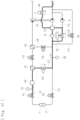
Fig. 1] Fig. 1 schematically illustrates a blood purification apparatus to which a dialysate extraction device according to the present invention is applied. - [
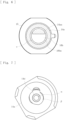
Fig. 2] Fig. 2 is a perspective view of a dialysate extraction device according to an embodiment of the present invention. - [
Fig. 3] Fig. 3 is a three-view drawing of the dialysate extraction device. - [
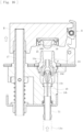
Fig. 4] Fig. 4 illustrates a section taken along line IV-IV given inFig. 3 . - [
Fig. 5] Fig. 5 illustrates a section taken along line V-V given inFig. 3 . - [
Fig. 6] Fig. 6 illustrates a section taken along line VI-VI given inFig. 3 . - [
Fig. 7] Fig. 7 illustrates a section taken along line VII-VII given inFig. 3 . - [
Fig. 8] Fig. 8 is an exploded perspective view of the dialysate extraction device, illustrating a collecting part of a dialysate extraction port, a cap member, and a seal member that are seen from above. - [
Fig. 9] Fig. 9 is an exploded perspective view of the dialysate extraction device, illustrating the collecting part of the dialysate extraction port, the cap member, and the seal member that are seen from below. - [
Fig. 10] Fig. 10 is a five-view drawing of the seal member included in the dialysate extraction device. - [
Fig. 11] Fig. 11 is a five-view drawing of the cap member included in the dialysate extraction device. - [
Fig. 12] Fig. 12 schematically illustrates how fluid flows in the dialysate extraction device. - [
Fig. 13] Fig. 13 schematically illustrates a state where sealing by a close-fitting part of the seal member included in the dialysate extraction device is undone. - [
Fig. 14] Fig. 14 schematically illustrates the dialysate extraction device attached to a dialysate flow route provided in the blood purification apparatus (with the collecting part closed). - [
Fig. 15] Fig. 15 schematically illustrates the dialysate extraction device attached to the dialysate flow route provided in the blood purification apparatus (with the collecting part closed). - [
Fig. 16] Fig. 16 schematically illustrates the dialysate extraction device attached to the dialysate flow route provided in the blood purification apparatus (with the collecting part open). - [
Fig. 17] Fig. 17 schematically illustrates the blood purification apparatus to which the dialysate extraction device according to the present invention is applied (with a pressurizing pump generating a negative pressure). - [
Fig. 18] Fig. 18 schematically illustrates the blood purification apparatus to which the dialysate extraction device according to the present invention is applied (with an ultrafiltration pump generating a negative pressure). - [
Fig. 19] Fig. 19 schematically illustrates the blood purification apparatus to which the dialysate extraction device according to the present invention is applied (with a duplex pump generating a negative pressure). Description of Embodiments - Embodiments of the present invention will now be described specifically with reference to the drawings.
- A dialysate extraction device according to an embodiment is provided to a blood purification apparatus intended for blood purification treatment (hemodialysis treatment) and is capable of collecting dialysate. As illustrated in
Fig. 1 , the applicable blood purification apparatus basically includes a blood circuit, in which anarterial blood circuit 2 and avenous blood circuit 3 are connected to a dialyzer 1 (a blood purifier); and a dialysis device B, which includes a dialysate introduction line L1 and a dialysate discharge line L2. - The
dialyzer 1 is intended to purify blood and is connected to thearterial blood circuit 2 and thevenous blood circuit 3, included in the blood circuit, at respective ports 1a and 1b. Thedialyzer 1 is also connected to the dialysate introduction line L1 and the dialysate discharge line L2 atrespective ports arterial blood circuit 2 is provided with a blood pump 4, which is a peristaltic pump. Activating the blood pump 4 enables fluid such as blood to be delivered to flow through the blood circuit. - An arterial puncture needle a and a venous puncture needle b are attachable to the distal end of the
arterial blood circuit 2 and the distal end of thevenous blood circuit 3, respectively. When the blood pump 4 is activated while a patient is punctured with the arterial puncture needle a and the venous puncture needle b, the patient's blood is collected through the arterial puncture needle a and is caused to extracorporeally circulate through the blood circuit. After the blood is purified and ultrafiltered by thedialyzer 1, the blood is returned to the patient through the venous puncture needle b. Thearterial blood circuit 2 is provided with an arterial air-trap chamber 5 and, at a distal portion thereof, a clamping device Va. Thevenous blood circuit 3 is provided with a venous air-trap chamber 6 and, at a distal portion thereof, a clamping device Vb. - The dialysate introduction line L1 and the dialysate discharge line L2 are connected to a
duplex pump 7. Theduplex pump 7 is configured to cause dialysate, which is prepared to have a predetermined concentration, to be supplied to thedialyzer 1 and to be discharged from thedialyzer 1. Specifically, theduplex pump 7 is connected astride the dialysate introduction line L1 and the dialysate discharge line L2. Activating theduplex pump 7 enables the dialysate to flow in such a manner as to be introduced into thedialyzer 1 through the dialysate introduction line L1 and to be discharged from thedialyzer 1 through the dialysate discharge line L2. - The dialysate introduction line L1 is provided with
filters dialyzer 1 is filterable by thefilters - The dialysate discharge line L2 is provided with detour lines L3 and L4, which detour the
duplex pump 7. The detour line L3 is provided with anultrafiltration pump 8. Hence, activating theultrafiltration pump 8 in the process of causing the patient's blood to extracorporeally circulate through the blood circuit enables the blood flowing in thedialyzer 1 to be ultrafiltered so that water is removed therefrom. The dialysate discharge line L2 is further provided with a pressurizingpump 9 on the upstream side (the left side in the drawing) relative to theduplex pump 7. The pressurizingpump 9 is a cascade pump and is capable of adjusting the fluid pressure in the dialysate discharge line L2 at the duplex pump 7 (a fluid delivery pump). Between the pressurizingpump 9 and theduplex pump 7 is provided achamber 13, from which a detour line L5 extends. - The dialysate discharge line L2 is further provided with a pressure detection sensor S2 on the downstream side relative to an electromagnetic valve V2 (between the connection to the bypass line L7 and the connection to the bypass line L8). The pressure detection sensor S2 is capable of detecting the pressure inside the flow route (the fluid pressure in the flow route). The dialysate discharge line L2 and the detour lines L4 and L5 branching off therefrom are provided with the electromagnetic valve V2 and electromagnetic valves V5 and V5, respectively. The electromagnetic valves V2, V5, and V6 are capable of closing and opening the flow route at arbitrary timings. The dialysate discharge line L2 is also provided with a detour line L6, which extends from a point between the connection to the detour line L4 and the pressurizing
pump 9 and reaches the detour line L3. The detour line L6 is provided with a relief valve VL. - A dialysate supply line La is connected at one end thereof to a collecting
part 14a of adialysate extraction port 14 of thedialysate extraction device 10, and at the other end thereof to the blood circuit (in the present embodiment, to the venous air-trap chamber 6 connected to the venous blood circuit 3), thereby providing a flow route through which the dialysate in the dialysate introduction line L1 is suppliable to the blood circuit. The dialysate supply line La is provided with a clamping device Vc. The clamping device Vc is openable and closable at arbitrary timings. In the present embodiment, the other end of the dialysate supply line La is connected to the venous air-trap chamber 6. Alternatively, the other end of the dialysate supply line La may be connected to another element of the blood circuit (for example, the arterial air-trap chamber 5 connected to thearterial blood circuit 2, or any other element). - The dialysate introduction line L1 according to the present embodiment is provided with the
dialysate extraction device 10, which is capable of collecting the dialysate flowing in the dialysate introduction line L1. As illustrated inFigs. 8, 9 , and14 to 16 , thedialysate extraction device 10 includes thedialysate extraction port 14, acap member 15, and aseal member 16. Thedialysate extraction port 14 is connected to the flow route for dialysate (the dialysate introduction line L1) and includes the collectingpart 14a, to which the dialysate flowing in the flow route is collectable. Thecap member 15 is attachable to and detachable from the collectingpart 14a of thedialysate extraction port 14. Theseal member 16 is attached to thecap member 15 and is configured to seal the collectingpart 14a with thecap member 15 attached to the collectingpart 14a. Thedialysate extraction device 10 is fixed to the dialysis device B such that, as illustrated inFigs. 4 and 5 , the axis (the longitudinal direction) of the dialysate extraction port 14 (the collectingpart 14a) extends horizontally. Alternatively, considering the ease of operation, thedialysate extraction device 10 may be fixed to the dialysis device B such that the axis (the longitudinal direction) of the dialysate extraction port 14 (the collectingpart 14a) extends at a predetermined angle to the horizontal direction. - The
dialysate extraction port 14 includes the collectingpart 14a, a first extractingmember 14b, a second extractingmember 14c, and a third extractingmember 14d. The dialysate in the dialysate introduction line L1 is collectable to the collectingpart 14a. The first extractingmember 14b is connected to the dialysate introduction line L1. The second extractingmember 14c is located inside the first extractingmember 14b. The third extractingmember 14d is fitted on the second extractingmember 14c and has a flow route thereinside. As illustrated inFigs. 4 and 5 , the collectingpart 14a has an inner peripheral surface 14aa and a tip 14ab. A connector (not illustrated) provided at one end of the dialysate supply line La (seeFig. 1 ) is insertable into the collectingpart 14a. The inner peripheral surface 14aa has an internal thread 14ac, along which the connector is screwable. - The first extracting
member 14b of thedialysate extraction port 14 according to the present embodiment is provided with an introduction port T1 and an ejection port T2, to which an introduction end L1a and an ejection end L1b of the dialysate introduction line L1 are connected, respectively. A flow route for fluid extends through the second extractingmember 14c and the third extractingmember 14d and communicates with the introduction port T1. The flow route is provided with acheck valve 18. Thecheck valve 18 allows the flow of the fluid from the dialysate supply line La toward the blood circuit but stops the flow of the fluid from the blood circuit toward the dialysate introduction line L1. - The distal end of the third extracting
member 14d is located inside the collectingpart 14a and is open, so that the fluid flowing in the flow route extending through the second extractingmember 14c and the third extractingmember 14d reaches the inside of the collectingpart 14a. Thus, a first flow route α (seeFigs. 4, 5 , and7 ) is provided for the fluid (such as a cleaning solution or a disinfecting solution) flowing in the dialysate introduction line L1 to flow toward the collectingpart 14a. Furthermore, a gap of a predetermined size is provided between the outer peripheral surface of the third extractingmember 14d and the inner peripheral surface 14aa of the collectingpart 14a. Hence, with thecap member 15 being in the closing state, a second flow route β (seeFigs. 4, 5 , and7 ) is provided for the fluid having flowed through the first flow route α to flow toward the dialysate introduction line L1. - Specifically, with the
cap member 15 detached from the dialysate extraction port 14 (seeFig. 16 ), the dialysate introduced from the introduction port T1 flows through the first flow route α, is discharged from the collectingpart 14a, and is supplied into the blood circuit through the dialysate supply line La. In contrast, with thecap member 15 attached to the dialysate extraction port 14 (seeFigs. 14 and15 ), the dialysate introduced into the first flow route α flows into the second flow route β and returns into the dialysate introduction line L1 through the ejection port T2. - As illustrated in
Figs 14 to 16 , thecap member 15 according to the present embodiment is held by a lid member H. The lid member H is attached to ashaft member 17, which is movable in the top-bottom direction. When the lid member H is lifted up, as illustrated inFig. 16 , thecap member 15 is detached from the collectingpart 14a of thedialysate extraction port 14. When the lid member H is pulled down, as illustrated inFigs. 14 and15 , thecap member 15 is attached to the collectingpart 14a of thedialysate extraction port 14. Reference numeral R in the drawings denotes a locking member, which locks the lid member H with thecap member 15 attached to thedialysate extraction port 14. - The
seal member 16 is made of a flexible material such as a resin material or a rubber material and includes a close-fittingpart 16a. As illustrated inFigs. 2 to 7 , theseal member 16 is integrated with thecap member 15 by being fitted in a space provided in thecap member 15. With thecap member 15 attached to the collectingpart 14a, theseal member 16 covers and seals the opening of the collectingpart 14a. The close-fittingpart 16a closely fits on the outer peripheral surface of the collectingpart 14a of thedialysate extraction port 14, thereby sealing (tightly closing) the collectingpart 14a. - With the
cap member 15 attached to the collectingpart 14a, theseal member 16 prevents the dialysate flowing in the dialysate introduction line L1 from leaking to the outside and allows the fluid, such as a cleaning solution or a disinfecting solution, flowing in the dialysate introduction line L1 to reach the tip 14ab of the collectingpart 14a. Such a configuration enables assured cleaning or disinfection of the tip 14ab and a part therearound (including a part facing a space produced between the close-fittingpart 16a and the tip 14ab). - As illustrated in
Figs. 4 to 6 , theseal member 16 according to the present embodiment includes aprojection 16b, which projects toward the inside of the collectingpart 14a. Theprojection 16b has an outer peripheral surface 16ba, which faces the inner peripheral surface 14aa of the collectingpart 14a with a gap in between. Thus, theprojection 16b defines an inflow route γ. When the sealing by the close-fittingpart 16a is undone, outside air is allowed to flow into the inflow route γ. - More specifically, as illustrated in
Fig. 13 , theprojection 16b according to the present embodiment has a tip 16bb, which is to be located on the inner side (the left side inFig. 13 ) of the collectingpart 14a relative to a position P1. The position P1 is reached by the close-fittingpart 16a when the sealing of the collectingpart 14a is undone. Thus, the inflow route γ is kept secured when the sealing is undone. As illustrated inFig. 6 , the inflow route γ extends over the entire periphery of the outer peripheral surface 16ba of theprojection 16b. - Therefore, in the process of detaching the
cap member 15 from the collectingpart 14a, when the close-fittingpart 16a reaches the position P1 and the sealing is undone, outside air flows through the inflow route γ into the collectingpart 14a at a high flow speed. Hence, any fluid adhered to and around the tip 14ab of the collectingpart 14a is prevented from leaking to the outside. That is, in the process of detaching thecap member 15 from the collectingpart 14a, the volume inside the collectingpart 14a gradually increases, and the inner pressure decreases. Therefore, when the close-fittingpart 16a reaches the position P1 and the sealing is undone, outside air flows into the inflow route γ with a great momentum and flows into the collectingpart 14a together with any fluid adhered to the tip 14ab of the collectingpart 14a. - As illustrated in
Fig. 12 , theprojection 16b according to the present embodiment is shaped asymmetrically in the top-bottom direction with a lower portion thereof having a greater length of projection than an upper portion thereof. Specifically, in the present embodiment, thedialysate extraction device 10 is fixed such that the axis (the longitudinal direction) of the dialysate extraction port 14 (the collectingpart 14a) extends horizontally. In a side view of theprojection 16b, the lower portion has a greater length of projection than the upper portion. - Accordingly, the tip 16bb of the
projection 16b has a surface inclined downward. Therefore, the fluid, such as a cleaning solution or a disinfecting solution, discharged through the first flow route α toward theprojection 16b flows obliquely upward along the tip 16bb to an upper portion of the inflow route γ and then flows in the peripheral direction along the outer peripheral surface 16ba of theprojection 16b. The fluid, such as a cleaning solution or a disinfecting solution, having flowed in the peripheral direction along the outer peripheral surface 16ba of theprojection 16b flows into a lower portion of the inflow route γ, reaches the second flow route β, and flows into the dialysate introduction line L1. - The fluid adhered to the
projection 16b accumulates on the lower side of theprojection 16b under its own weight. Considering such a situation, the length of projection of theprojection 16b according to the present embodiment is made greater in the lower portion than in the upper portion. That is, the length of the inflow route γ is made greater on the lower side of theprojection 16b. Such a configuration causes the fluid accumulated on the lower side of theprojection 16b under its own weight to flow inward of the collectingpart 14a together with outside air. - As illustrated in
Fig. 11 , thecap member 15 according to the present embodiment includes apositioning part 15a, where theseal member 16 is positionable. Specifically, thecap member 15 has thepositioning part 15a, which is a cut provided at a predetermined position. On the other hand, as illustrated inFig. 10 , theseal member 16 has aprotrusion 16c, which is fittable into thepositioning part 15a. Theseal member 16 is attached to thecap member 15 such that theprotrusion 16c is fitted into thepositioning part 15a. Thus theseal member 16 is positionable. - The blood purification apparatus applicable to the present embodiment is configured to generate a negative pressure in the
dialysate extraction port 14 at a predetermined timing before thecap member 15 is detached from the collectingpart 14a. A device for generating a negative pressure in thedialysate extraction port 14 may be a fluid delivery unit configured to deliver the dialysate in the dialysate introduction line L1 (the dialysate flow route). In the present embodiment, the pressurizingpump 9, which is a cascade pump, is activated to generate a negative pressure in thedialysate extraction port 14. - Now, how to generate a negative pressure in the
dialysate extraction port 14 by activating the pressurizingpump 9 will be described with reference toFig. 17 . - First, the distal end c of the dialysate introduction line L1 and the distal end d of the dialysate discharge line L2 are connected to each other. Furthermore, the electromagnetic valves V1, V2, V4, V5, and V7 are closed (the flow route is closed), whereas the electromagnetic valves V3 and V6 are opened (the flow route is opened). Then, the pressurizing
pump 9 is activated. In this state, theultrafiltration pump 8 and theduplex pump 7 are not in operation. Thus, the volume of the dialysate in a portion of the dialysate introduction line L1 where thedialysate extraction device 10 is connected is reduced. Accordingly, a negative pressure is generated in thedialysate extraction port 14. - Subsequently, if the electromagnetic valves V1, V3, and V7 are closed, the negative pressure generated in the
dialysate extraction device 10 can be retained. In this state, for example, if information that the negative pressure is retained is provided on a display monitor or the like, the detaching of thecap member 15 from the collectingpart 14a can be prompted. If the electromagnetic valve V4 is opened with the negative pressure in thedialysate extraction device 10 retained, activating theduplex pump 7 can cause the dialysate to flow through the bypass line L8. - The negative pressure in the
dialysate extraction port 14 may alternatively be generated by activating theultrafiltration pump 8. In that case, as illustrated inFig. 18 , the distal end c of the dialysate introduction line L1 and the distal end d of the dialysate discharge line L2 are connected to each other. Furthermore, the electromagnetic valves V1, V2, V4, V5, V6, and V7 are closed (the flow route is closed), whereas the electromagnetic valve V3 is opened (the flow route is opened). Then, theultrafiltration pump 8 is activated. Thus, the volume of the dialysate in the portion of the dialysate introduction line L1 where thedialysate extraction device 10 is connected is reduced. Accordingly, a negative pressure is generated in thedialysate extraction port 14. In this state, if the electromagnetic valves V1, V3, and V7 are closed, the negative pressure generated in thedialysate extraction device 10 can be retained. - As another alternative, the negative pressure in the
dialysate extraction port 14 may be generated by activating theduplex pump 7. In that case, as illustrated inFig. 19 , the distal end c of the dialysate introduction line L1 and the distal end d of the dialysate discharge line L2 are connected to each other. Furthermore, the electromagnetic valves V1, V2, V4, V5, V6, and V7 are closed (the flow route is closed), whereas the electromagnetic valve V3 is opened (the flow route is opened). Then, theduplex pump 7 is activated. Thus, the volume of the dialysate in the portion of the dialysate introduction line L1 where thedialysate extraction device 10 is connected is reduced. Accordingly, a negative pressure is generated in thedialysate extraction port 14. In this state, if the electromagnetic valves V1, V3, and V7 are closed, the negative pressure generated in thedialysate extraction device 10 can be retained. - According to the present embodiment, the
seal member 16 includes the close-fittingpart 16a configured to seal the collectingpart 14a by closely fitting on the outer peripheral surface of thedialysate extraction port 14, and theprojection 16b projecting toward the inside of the collectingpart 14a and having the outer peripheral surface 16ba that faces the inner peripheral surface 14aa of the collectingpart 14a with a gap in between. Theprojection 16b defines the inflow route γ into which outside air is allowed to flow when the sealing by the close-fittingpart 16a is undone. Such a configuration assuredly prevents the scattering of the fluid that may occur when thecap member 15 is detached from the collectingpart 14a. - According to the present embodiment, the
projection 16b has the tip 16bb to be located on the inner side of the collectingpart 14a relative to the position P1 that is reached by the close-fittingpart 16a when the sealing of the collectingpart 14a is undone. Furthermore, the inflow route γ is kept secured when the sealing is undone. Therefore, when the sealing of the collectingpart 14a is undone, the inflow route γ is kept secured without fail. Such a configuration more assuredly prevents the scattering of the fluid that may occur when thecap member 15 is detached from the collectingpart 14a. - The inflow route γ extends over the entire periphery of the outer peripheral surface 16ba of the
projection 16b. Such a configuration causes any fluid adhered to and around the tip 14ab of the collectingpart 14a to flow inward of the collectingpart 14a, together with air, in an area along the entire periphery. Thedialysate extraction port 14 has the first flow route α through which the fluid flowing in the dialysate introduction line L1 is allowed to flow toward the collectingpart 14a, and the second flow route β through which the fluid having flowed through the first flow route α is allowed to flow toward the dialysate introduction line L1. Furthermore, theprojection 16b is shaped asymmetrically in the top-bottom direction with the lower portion thereof having a greater length of projection than the upper portion thereof. Such a configuration smoothly causes the fluid, such as a cleaning solution or a disinfecting solution, having flowed through the first flow route α and discharged toward theprojection 16b to flow from the second flow route β to the dialysate introduction line L1. - The
cap member 15 includes thepositioning part 15a where theseal member 16 is positionable. Such a configuration enables theprojection 16b shaped asymmetrically in the top-bottom direction to be assuredly oriented in a predetermined way such that a portion thereof having a greater length of projection is located on the lower side while a portion thereof having a smaller length of projection is located on the upper side. - In the blood purification apparatus applied to the present embodiment, a negative pressure is generated in the
dialysate extraction port 14 at a predetermined timing before thecap member 15 is detached from the collectingpart 14a. Such a configuration assuredly prevents the scattering of the fluid that may occur when thecap member 15 is detached from the collectingpart 14a. According to the present embodiment, the negative pressure in thedialysate extraction port 14 is generated by activating the fluid delivery unit (the pressurizingpump 9, theultrafiltration pump 8, or the duplex pump 7) configured to deliver the dialysate in the dialysate introduction line L1. Thus, a component necessary for blood purification treatment is utilizable. In particular, if the fluid delivery unit to be activated is the pressurizingpump 9 that is a cascade pump, the volume is gradually reduced by a constant volume without pulsation, realizing a smooth generation of a negative pressure. - While some embodiments have been described above, the present invention is not limited thereto. For example, the
projection 16b does not necessarily need to be shaped asymmetrically in the top-bottom direction, as long as theprojection 16b defines the inflow route γ into which outside air is allowed to flow when the sealing by the close-fittingpart 16a is undone. Specifically, theprojection 16b may be a projection having a cylindrical shape (whether hollow or solid). The applicable blood purification apparatus is not limited to the one configured to generate a negative pressure in thedialysate extraction port 14 at a predetermined timing before thecap member 15 is detached from the collectingpart 14a. The blood purification apparatus does not necessarily need to have such a function. - The blood purification apparatus to which any of the above embodiments is applied may be provided in any mode. For example, the blood purification apparatus may be any of the following: an apparatus in which the dialysate is to be introduced or discharged by using a chamber instead of the
duplex pump 7, an apparatus including a blood purifier in a mode other than thedialyzer 1, and an apparatus including neither the pressure detection device S1 nor the pressure detection device S2. While the above embodiments each concern a case where the dialysate extraction device is provided to the dialysate introduction line L1 provided in the dialysis device, the dialysate extraction device may be provided to another dialysate flow route provided in the dialysis device. - The present invention is also applicable to any dialysate extraction device or any blood purification apparatus having a different appearance, additional functions, or the like within the spirit of the present invention.
-
- 1 dialyzer (blood purifier)
- 2 arterial blood circuit
- 3 venous blood circuit
- 4 blood pump
- 5 arterial air-trap chamber
- 6 venous air-trap chamber
- 7 duplex pump
- 8 ultrafiltration pump
- 9 pressurizing pump (cascade pump)
- 10 dialysate extraction device
- 11, 12 filter
- 13 chamber
- 14 dialysate extraction port
- 14a collecting part
- 14aa inner peripheral surface
- 14ab tip
- 14ac internal thread
- 14b first extracting member
- 14c second extracting member
- 14d third extracting member
- 15 cap member
- 15a positioning part
- 16 seal member
- 16a close-fitting part
- 16b projection
- 16ba outer peripheral surface
- 16bb tip
- 16c protrusion
- 17 shaft member
- 18 check valve
- L1 dialysate introduction line (dialysate flow route)
- L2 dialysate discharge line
- B dialysis device
- H lid member
- S1, S2 pressure detection sensor
- α first flow route
- β second flow route
- γ inflow route
Claims (8)
- A dialysate extraction device comprising:a dialysate extraction port connected to a dialysate flow route through which dialysate is to flow, the dialysate extraction port including a collecting part to which the dialysate flowing in the dialysate flow route is collectable;a cap member attachable to and detachable from the collecting part of the dialysate extraction port; anda seal member attached to the cap member and configured to seal the collecting part with the cap member attached to the collecting part,wherein the seal member includesa close-fitting part configured to seal the collecting part by closely fitting on an outer peripheral surface of the dialysate extraction port; anda projection projecting toward an inside of the collecting part and having an outer peripheral surface that faces an inner peripheral surface of the collecting part with a gap in between, the projection defining an inflow route into which outside air is allowed to flow when the sealing by the close-fitting part is undone.
- The dialysate extraction device according to Claim 1, wherein the projection has a tip to be located on an inner side of the collecting part relative to a position that is reached by the close-fitting part when the sealing of the collecting part is undone, and the inflow route is kept secured when the sealing is undone.
- The dialysate extraction device according to Claim 1 or 2, wherein the inflow route extends over an entire periphery of the outer peripheral surface of the projection.
- The dialysate extraction device according to Claim 3, wherein the dialysate extraction port has a first flow route through which fluid flowing in the dialysate flow route is allowed to flow toward the collecting part; and a second flow route through which the fluid having flowed through the first flow route is allowed to flow toward the dialysate flow route, and wherein the projection is shaped asymmetrically in a top-bottom direction with a lower portion of the projection having a greater length of projection than an upper portion of the projection.
- The dialysate extraction device according to Claim 4, wherein the cap member includes a positioning part where the seal member is positionable.
- A blood purification apparatus comprising the dialysate flow route to which the dialysate extraction device according to any of Claims 1 to 5 is attached,
wherein a negative pressure is generated in the dialysate extraction port at a predetermined timing before the cap member is detached from the collecting part. - The blood purification apparatus according to Claim 6, further comprising a fluid delivery unit configured to deliver dialysate in the dialysate flow route, wherein the negative pressure in the dialysate extraction port is generated by activating the fluid delivery unit.
- The blood purification apparatus according to Claim 7, wherein the fluid delivery unit is a cascade pump.
Applications Claiming Priority (2)
| Application Number | Priority Date | Filing Date | Title |
|---|---|---|---|
| JP2021173501A JP7767104B2 (en) | 2021-10-22 | 2021-10-22 | Dialysis fluid extraction device and blood purification device |
| PCT/JP2022/039048 WO2023068320A1 (en) | 2021-10-22 | 2022-10-20 | Dialysis solution extraction device and blood purification device |
Publications (2)
| Publication Number | Publication Date |
|---|---|
| EP4410326A1 true EP4410326A1 (en) | 2024-08-07 |
| EP4410326A4 EP4410326A4 (en) | 2025-07-30 |
Family
ID=86058308
Family Applications (1)
| Application Number | Title | Priority Date | Filing Date |
|---|---|---|---|
| EP22883624.3A Pending EP4410326A4 (en) | 2021-10-22 | 2022-10-20 | Dialysis solution extraction device and blood purification device |
Country Status (5)
| Country | Link |
|---|---|
| US (1) | US20240261479A1 (en) |
| EP (1) | EP4410326A4 (en) |
| JP (1) | JP7767104B2 (en) |
| CN (1) | CN118139656A (en) |
| WO (1) | WO2023068320A1 (en) |
Family Cites Families (6)
| Publication number | Priority date | Publication date | Assignee | Title |
|---|---|---|---|---|
| JP5813403B2 (en) * | 2011-06-23 | 2015-11-17 | 日機装株式会社 | Dialysate extraction device |
| JP6295147B2 (en) * | 2014-06-27 | 2018-03-14 | 日機装株式会社 | Dialysate extraction device |
| JP5851003B1 (en) * | 2014-09-12 | 2016-02-03 | 日機装株式会社 | Blood purification equipment |
| CN204181933U (en) * | 2014-11-03 | 2015-03-04 | 张家港市沙工医疗器械科技发展有限公司 | A kind of hemodialysis extracorporeal circulation pipeline probe tube parts |
| CN204282933U (en) | 2014-11-25 | 2015-04-22 | 浙江巨匠钢业有限公司 | A kind of communication tower |
| JP6466312B2 (en) * | 2015-12-14 | 2019-02-06 | 澁谷工業株式会社 | Method for operating hemodialyzer and hemodialyzer |
-
2021
- 2021-10-22 JP JP2021173501A patent/JP7767104B2/en active Active
-
2022
- 2022-10-20 EP EP22883624.3A patent/EP4410326A4/en active Pending
- 2022-10-20 CN CN202280070747.7A patent/CN118139656A/en active Pending
- 2022-10-20 WO PCT/JP2022/039048 patent/WO2023068320A1/en not_active Ceased
-
2024
- 2024-04-18 US US18/639,228 patent/US20240261479A1/en active Pending
Also Published As
| Publication number | Publication date |
|---|---|
| JP2023063157A (en) | 2023-05-09 |
| EP4410326A4 (en) | 2025-07-30 |
| US20240261479A1 (en) | 2024-08-08 |
| WO2023068320A1 (en) | 2023-04-27 |
| JP7767104B2 (en) | 2025-11-11 |
| CN118139656A (en) | 2024-06-04 |
Similar Documents
| Publication | Publication Date | Title |
|---|---|---|
| EP3162392B1 (en) | Blood purification device | |
| CN101242864B (en) | Blood component collection circuit and blood component collection device | |
| CN101309710B (en) | Blood purifying apparatus and method of examining the connection status of puncture needles thereof | |
| EP2883558A1 (en) | Blood purification device and priming method therefor | |
| EP2601985A1 (en) | Blood purifying device, and method for inspecting for liquid leakage therein | |
| EP2535065B1 (en) | Dialyzer | |
| EP2586474A1 (en) | Hemodialysis device | |
| EP2737915A1 (en) | Dialysate extraction device | |
| US10507275B2 (en) | Tube set for a blood handling apparatus and blood handling apparatus comprising a tube set | |
| US10610634B2 (en) | Blood purification apparatus | |
| EP3511035A1 (en) | Blood purification device | |
| EP3409306A1 (en) | Blood purification device | |
| US10314961B2 (en) | Dialysate-extracting apparatus | |
| US11554202B2 (en) | Blood purification apparatus and method of discharging bubbles therefrom | |
| US11406747B2 (en) | Extracorporeal circulation apparatus and method of discharging bubbles therefrom | |
| US20240261479A1 (en) | Dialysate extraction device and blood purification apparatus | |
| WO2008117899A1 (en) | Slide type hemofiltration device | |
| EP3603697A1 (en) | Blood purification device and method for controlling same | |
| EP4327842A1 (en) | Blood purification device | |
| EP3603695B1 (en) | Blood purification device and priming method thereof | |
| CN119451717A (en) | Blood purification device |
Legal Events
| Date | Code | Title | Description |
|---|---|---|---|
| STAA | Information on the status of an ep patent application or granted ep patent |
Free format text: STATUS: THE INTERNATIONAL PUBLICATION HAS BEEN MADE |
|
| PUAI | Public reference made under article 153(3) epc to a published international application that has entered the european phase |
Free format text: ORIGINAL CODE: 0009012 |
|
| STAA | Information on the status of an ep patent application or granted ep patent |
Free format text: STATUS: REQUEST FOR EXAMINATION WAS MADE |
|
| 17P | Request for examination filed |
Effective date: 20240429 |
|
| AK | Designated contracting states |
Kind code of ref document: A1 Designated state(s): AL AT BE BG CH CY CZ DE DK EE ES FI FR GB GR HR HU IE IS IT LI LT LU LV MC ME MK MT NL NO PL PT RO RS SE SI SK SM TR |
|
| DAV | Request for validation of the european patent (deleted) | ||
| DAX | Request for extension of the european patent (deleted) | ||
| A4 | Supplementary search report drawn up and despatched |
Effective date: 20250701 |
|
| RIC1 | Information provided on ipc code assigned before grant |
Ipc: A61M 1/16 20060101AFI20250625BHEP Ipc: A61M 1/34 20060101ALI20250625BHEP Ipc: A61M 39/16 20060101ALI20250625BHEP Ipc: A61M 39/20 20060101ALI20250625BHEP |